Embed Size (px)
Citation preview
8/22/2019 Mackie PPM1012 12 Channel Powered Mixer Manual
http://slidepdf.com/reader/full/mackie-ppm1012-12-channel-powered-mixer-manual 1/36
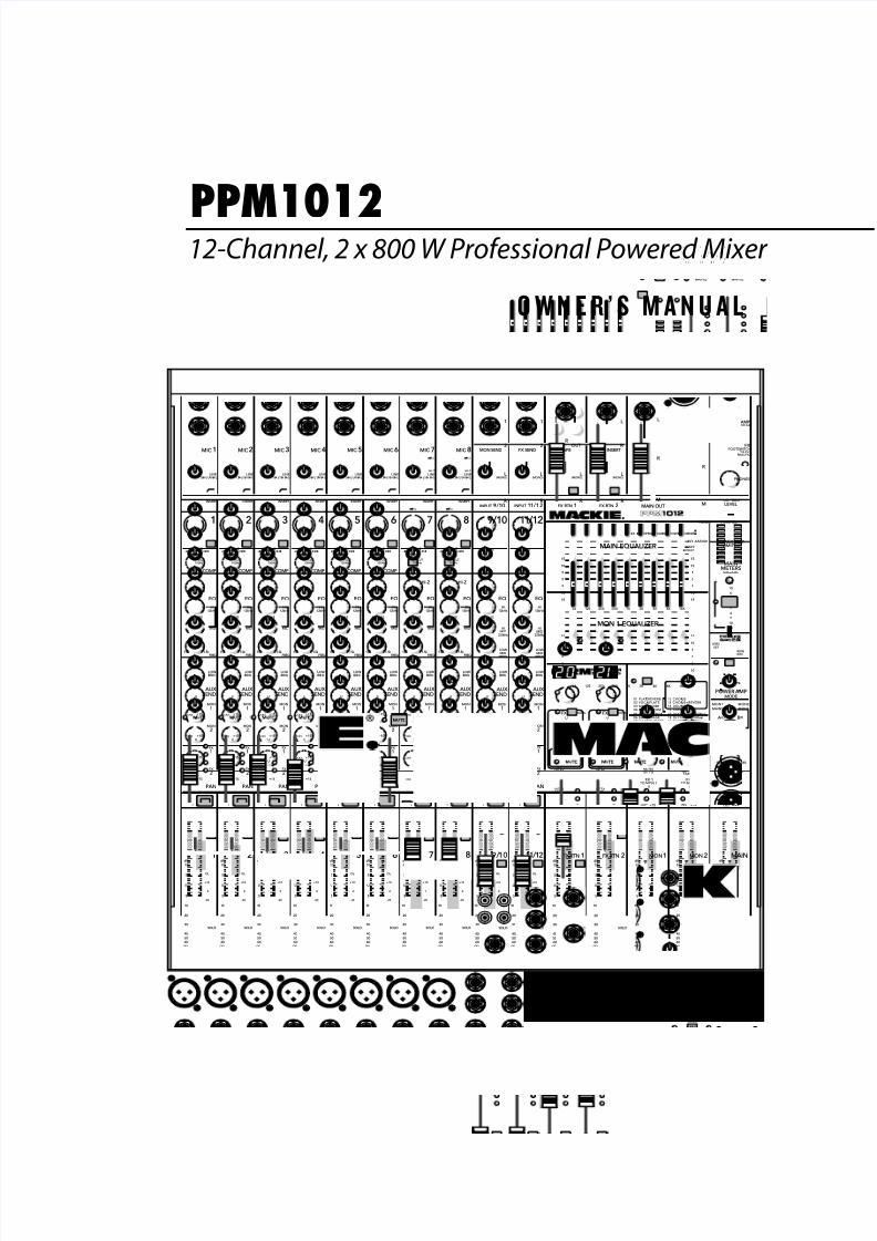
PPM1012
>F= 4 A ½ B < 0 = D 0 ;
12-Channel, 2 x 800 W Professional Powered Mixer
80HzLOW
MIC1 MIC2 MIC3 MIC4 MIC5 MIC6 MIC 7 MIC 8
INPUT
( BA L/ UN BA L) ( BA L/ UN BA L) ( BA L/ UN BA L) ( BA L/ UN BA L) ( BA L/ UN BA L) ( BA L/ UN BA L) ( BA L/ UN BA L) ( BA L/ UN BA L)
INSERT INSERT INSERT INSERT INSERT INSERT INSERT INSERT
GAIN
U
-20
LAMP12V0.5A
L
R
FX SEND TAPE
OUTIN
L
MON SEND
FX RTN
(MONO)
MID
FREQ
RL
U
GAIN
M I CG A I N
0 +50-20dB +30dB
600
1.5k 150
8k 100
O FF MAX
U
GAIN
M I CG A I N
0 + 50-20dB +30dB
U
GAIN
M I CG A I N
0 + 50- 20 dB +30 dB
U
GAIN
M I CG A I N
0 + 50-20dB +30dB
U
GAIN
M I CG A I N
0 +50-20dB +30dB
U
GAIN
M I CG A I N
0 + 50-20dB +30dB
U
GAIN
M I CG A I N
0 + 50- 20 dB +30 dB
U
GAIN
M I CG A I N
0 + 50-20dB +30dB
1 9/10 11/122 3 4 5 6 7 8
SOLO
OL
+10
0
-20
SOLO
OL
+10
0
-20
1 9/10 11/122 3 4 5 6 7 8
EQ EQ
OFF MAX OFF MAX OFF MAX OFF MAX OFF MAX
12kHzHI
LOWCUT100Hz
U
+15-15U
+15-15U
+15-15
U
+15-15
+20
12kHzHI
80HzLOW
HIMID
2.5kHz
LOW
MID400Hz
U
+15-15U
+15-15U
+15-15
U
+15-15
12kHzHI
80HzLOW
HIMID
2.5kHz
LOW
MID400Hz
GAIN
U
-20
PAN
AUX SEND
EQ
COMP COMP COMP COMP COMP COMP
+20
1
2
L
R
(MONO)L
R
(MONO)L
R
(MONO)
1
2
FX RTN
L
R
L
R
M
L
R
M
MON
1
MON
2
FX
1
FX
2
U
+15 OO
U
+15 OO
U
+15 OO
U
+15 OO
-15
U
+15
-15
U
+15
-15
U
+15
80HzLOW
MID
FREQ
RL
600
1.5k 150
8k 100
EQ
12kHzHI
PAN
AUX SEND
MON
1
MON
2
FX
1
FX
2
U
+15 OO
U
+15 OO
U
+15 OO
U
+15 OO
-15
U
+15
-15
U
+15
-15
U
+15
80HzLOW
MID
FREQ
RL
600
1.5k 150
8k 100
EQ
12kHzHI
PAN
AUX SEND
MON
1
MON
2
FX
1
FX
2
U
+15 OO
U
+15 OO
U
+15 OO
U
+15 OO
-15
U
+15
-15
U
+15
-15
U
+15
80HzLOW
MID
FREQ
RL
600
1.5k 150
8k 100
EQ
12kHzHI
PAN
AUX SEND
MON
1
MON
2
FX
1
FX
2
U
+15 OO
U
+15 OO
U
+15 OO
U
+15 OO
-15
U
+15
-15
U
+15
-15
U
+15
80HzLOW
MID
FREQ
RL
600
1.5k 150
8k 100
EQ
12kHzHI
PAN
AUX SEND
MON
1
MON
2
FX
1
FX
2
U
+15 OO
U
+15 OO
U
+15 OO
U
+15 OO
-15
U
+15
-15
U
+15
-15
U
+15
80HzLOW
MID
FREQ
RL
600
1.5k 150
8k 100
EQ
12kHzHI
PAN
AUX SEND
MON
1
MON
2
FX
1
FX
2
U
+15 OO
U
+15 OO
U
+15 OO
U
+15 OO
-15
U
+15
-15
U
+15
-15
U
+15
80HzLOW
MID
FREQ
RL
600
1.5k 150
8k 100
EQ
12kHzHI
PAN
AUX SEND
MON
1
MON
2
FX
1
FX
2
U
+15 OO
U
+15 OO
U
+15 OO
U
+15 OO
-15
U
+15
-15
U
+15
-15
U
+15
80HzLOW
MID
FREQ
RL
600
1.5k 150
8k 100
EQ
12kHzHI
PAN
AUX SEND
MON
1
MON
2
FX
1
FX
2
U
+15 OO
U
+15 OO
U
+15 OO
U
+15 OO
RL
PAN
AUX
SEND
MON
1
MON
2
FX
1
FX
2
U
+15 OO
U
+15 OO
U
+15 OO
U
+15 OO
RL
PAN
AUX
SEND
MON
1
FX
MON
2
FX
1
FX
2
U
+15 OO
U
+15 OO
U
+15 OO
U
+15 OO
-15
U
+15
-15
U
+15
-15
U
+15
1 FX 2
9 1 210 / INPUT 11 12 / MAIN OUT
MAIN INSERT
TAPDELAY
INTFX MUTE
TAPDELAY
INTFX MUTE
TAPTOEDIT
01 PLATEREVERB02 VOCALPLATE
03 WARMROOM04 BRIGHTROOM
13 CHORUS14 CHORUS+REVERB
15 DOUBLER16 TAPESLAP
05 WARMLOUNGE
06 SMALLSTAGE07 WARMTHEATER08 BRIGHTSTAGE
09 WARMHALL10 CONCERTHALL
11 CATHEDRAL12 GATEDREVERB
17 DLY1BRIGHT(350ms)
18 DLY1WARM(300ms)19 DLY2BRIGHT(250ms)20 DLY2WARM(200ms)
21 DLY3BRIGHT(175ms)22 DLY3WARM(150ms)
23 CHORUS+DLY(300ms)24 REVERB+ DLY(200ms)
15
15
10
10
5
5
0
15
15
10
10
5
5
0
16K 8K 4K 2K 1K 50025012563
HI-Z HI-ZOL
4
6
3
10
15
7
10
20
30
0
2
U
+20 OO
TAPE IN
BREAK
MUTESCH 1-12
U
+15 OO
U
+15 OO
TO MON 1 TO MON 2
FX 1 FX 1MONO OUT
LPF
OOMAX
75Hz
100 180
120
200Hz
0dB=0dBu
LEVEL
SET
RUDE
SOLO
MAINMON2
EQ ASSIGN
MAINMETERS
RL
PHANTOMPOWER
MAIN EQUALIZER
MON 1 EQUALIZER
15
15
10
10
5
5
0
15
15
10
10
5
5
0
16K 8K 4K 2K 1K 50025012563
SIG/OLSIG/OL
U
+15 OO
SEND MASTER
U
+15 OO
SEND MASTER
LOWCUT100Hz
LOWCUT100Hz
LOWCUT100Hz
LOWCUT100Hz
LOWCUT100Hz
LOWCUT100Hz
LOWCUT100Hz
dB
10
OO
5
5
U
dB
30
20
10
OO
40
50
5
5
U
60
SOLO
OL
+10
0
-20
dB
30
20
10
OO
40
50
5
5
U
60
SOLO
OL
+10
0
-20
dB
30
20
10
OO
40
50
5
5
U
60
SOLO
OL
+10
0
-20
dB
30
20
10
OO
40
50
5
5
U
60
SOLO
OL
+10
0
-20
dB
30
20
10
OO
40
50
5
5
U
60
SOLO
OL
+10
0
-20
dB
30
20
10
OO
40
50
5
5
U
60
SOLO
OL
+10
0
-20
dB
30
20
10
OO
40
50
5
5
U
60
SOLO
OL
+10
0
-20
dB
30
20
10
OO
40
50
5
5
U
60
SOLO
OL
+10
0
-20
dB
30
20
10
OO
40
50
5
5
U
60
SOLO
dB
30
20
10
OO
40
50
5
5
U
60
SOLO
dB
30
20
10
OO
40
50
5
5
U
60
SOLO
dB
30
20
10
OO
40
50
5
5
U
60
SOLO
dB
30
20
10
OO
40
50
5
5
U
60
dB
30
20
10
OO
40
50
5
5
U
60
FX RTN1 FX RTN 2 MON1 MON2 MAIN
FOOTSWITCHTIP:FX1
RING:FX2
PHONES
FX
LEVEL
2X 800WPROFESSIONALPOWEREDMIXER
OOMAX
30
20
40
50
60
10 10 10 10 10 10 10 10 10 10 10 10 10 10 10
(L) (R)
MON1
MON2
MAINS
MON1
STEREOMAIN
A B
LINELINELINELINELINELINELINEHI-Z
LINEHI-Z
POWER AMPLIMITER
A B
POWER AMPMODE
I K I L I
K, I I I
I . . I L
I I . I I LI I L.
I: I L I I
R
8/22/2019 Mackie PPM1012 12 Channel Powered Mixer Manual
http://slidepdf.com/reader/full/mackie-ppm1012-12-channel-powered-mixer-manual 2/36
) GGD('()
G G D ( ' ( )
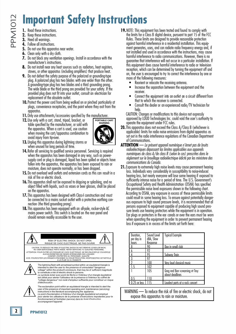
1. Read these instructions.2. Keep these instructions.3. Heed all warnings.4. Follow all instructions.5. Do not use this apparatus near water.6. Clean only with a dry cloth.
7. Do not block any ventilation openings. Install in accordance with themanufacturer’s instructions.8. Do not install near any heat sources such as radiators, heat registers,
stoves, or other apparatus (including amplifiers) that produce heat.9. Do not defeat the safety purpose of the polarized or grounding-type
plug. A polarized plug has two blades with one wider than the other.A grounding-type plug has two blades and a third grounding prong.The wide blade or the third prong are provided for your safety. If theprovided plug does not fit into your outlet, consult an electrician forreplacement of the obsolete outlet.
10. Protect the power cord from being walked on or pinched particularly at plugs, convenience receptacles, and the point where they exit from theapparatus.
11.Only use attachments/accessories specified by the manufacturer.12.Use only with a cart, stand, tripod, bracket, ortable specified by the manufacturer, or sold withthe apparatus. When a cart is used, use cautionwhen moving the cart/apparatus combination toavoid injury from tip-over.
13.Unplug this apparatus during lightning storms orwhen unused for long periods of time.
14.Refer all servicing to qualified service personnel. Servicing is requiredwhen the apparatus has been damaged in any way, such as power-supply cord or plug is damaged, liquid has been spilled or objects havefallen into the apparatus, the apparatus has been exposed to rain ormoisture, does not operate normally, or has been dropped.
15.Do not overload wall outlets and extension cords as this can result in arisk of fire or electric shock.
16. This apparatus shall not be exposed to dripping or splashing, and noobject filled with liquids, such as vases or beer glasses, shall be placedon the apparatus.
17. This apparatus has been designed with Class-I construction and must be connected to a mains socket outlet with a protective earthing con-nection (the third grounding prong).
18. This apparatus has been equipped with an all-pole, rocker-style ACmains power switch. This switch is located on the rear panel andshould remain readily accessible to the user.
19.NOTE: This equipment has been tested and found to comply withthe limits for a Class B digital device, pursuant to part 15 of the FCCRules. These limits are designed to provide reasonable protectionagainst harmful interference in a residential installation. This equip-ment generates, uses, and can radiate radio frequency energy and, ifnot installed and used in accordance with the instructions, may cause
harmful interference to radio communications. However, there is noguarantee that interference will not occur in a particular installation. Ifthis equipment does cause harmful interference to radio or televisionreception, which can be determined by turning the equipment off andon, the user is encouraged to try to correct the interference by one ormore of the following measures:
• Reorient or relocate the receiving antenna.• Increase the separation between the equipment and the
receiver.• Connect the equipment into an outlet on a circuit different from
that to which the receiver is connected.• Consult the dealer or an experienced radio/TV technician for
help.CAUTION: Changes or modifications to this device not expresslyapproved by LOUD Technologies Inc. could void the user's authority tooperate the equipment under FCC rules.
20. This apparatus does not exceed the Class A/Class B (whichever isapplicable) limits for radio noise emissions from digital apparatus asset out in the radio interference regulations of the Canadian Department of Communications.
ATTENTION — Le présent appareil numérique n’émet pas de bruits radioélectriques dépassant las limites applicables aux appareils numériques de class A/de class B (selon le cas) prescrites dans le réglement sur le brouillage radioélectrique édicté par les ministere des communications du Canada.
21. Exposure to extremely high noise levels may cause permanent hearingloss. Individuals vary considerably in susceptibility to noise-induced
hearing loss, but nearly everyone will lose some hearing if exposed tosufficiently intense noise for a period of time. The U.S. Government’sOccupational Safety and Health Administration (OSHA) has specifiedthe permissible noise level exposures shown in the following chart.According to OSHA, any exposure in excess of these permissible limitscould result in some hearing loss. To ensure against potentially danger-ous exposure to high sound pressure levels, it is recommended that allpersons exposed to equipment capable of producing high sound pres-sure levels use hearing protectors while the equipment is in operation.Ear plugs or protectors in the ear canals or over the ears must be wornwhen operating the equipment in order to prevent permanent hearingloss if exposure is in excess of the limits set forth here:
Important Safety Instructions
PORTABLE CART
WARNING
CAUTION AVIS RISK OF ELECTRIC SHOCK. DO NOT OPEN
RISQUE DE CHOC ELECTRIQUE. NE PAS OUVRIR
CAUTION: TO REDUCE THE RISK OF ELECTRIC SHOCK DO NOT REMOVE COVER (OR BACK)NO USER-SERVICEABLE PARTS INSIDE. REFER SERVICING TO QUALIFIED PERSONNEL
ATTENTION: POUR EVITER LES RISQUES DE CHOC ELECTRIQUE, NE PAS ENLEVER LE COUVERCLE. AUCUN ENTRETIEN DE PIECES INTERIEURES PAR L'USAGER.
CONFIER L'ENTRETIEN AU PERSONNEL QUALIFIE. AVIS: POUR EVITER LES RISQUES D'INCENDIE OU D'ELECTROCUTION, N'EXPOSEZ PAS CET ARTICLE
A LA PLUIE OU A L'HUMIDITE
The lightning flash with arrowhead symbol within an equilateral triangle isintended to alert the user to the presence of uninsulated "dangerousvoltage" within the product's enclosure, that may be of sufficient magnitudeto constitute a risk of electric shock to persons.Le symbole éclair avec point de flèche à l'intérieur d'un triangle équilatéral est utilisé pour alerter l'utilisateur de la présence à l'intérieur du coffret de"voltage dangereux" non isolé d'ampleur suffisante pour constituer un risqued'éléctrocution.
The exclamation point within an equilateral triangle is intended to alert theuser of the presence of important operating and maintenance (servicing)
instructions in the literature accompanying the appliance.Le point d'exclamation à l'intérieur d'un triangle équilatéral est employé pour alerter les utilisateurs de la présence d'instructions importantes pour lefonctionnement et l'entretien (service) dans le livret d'instructionaccompagnant l'appareil.
WARNING — To reduce the risk of fire or electric shock, do not expose this apparatus to rain or moisture.
Duration,per day inhours
Sound LeveldBA, SlowResponse
Typical Example
8 90 Duo in small club6 924 95 Subway Train3 972 100 Very loud classical music1.5 1021 105 Greg and Ben screaming at Troy
about deadlines0.5 1100.25 or less 115 Loudest parts at a rock concert
8/22/2019 Mackie PPM1012 12 Channel Powered Mixer Manual
http://slidepdf.com/reader/full/mackie-ppm1012-12-channel-powered-mixer-manual 3/36
*Fne\iËjDXelXc
F ne \i Ë j D Xe l X c
Part No. SW0704 Rev. E 05/09
©2009 LOUD Technologies Inc. All Rights Reserved. PDF pixels home grown and harvested in Woodinville, WA.
Don’t use guitar cords for speaker cables!
They’re not designed to handle speaker-level
signals and could overheat.
J\kk_\c\m\cj
It’s not even necessary to hear what you’re doing to
set optimal levels. But if you’d like to: Plug headphones
into the phones output jack, then turn up the phonesknob just a little.
1. Turn on the PPM1012 by pressing the top edge
of the power switch.
2. For one channel, press the solo switch in, and
the rude solo light will turn on.
3. Play something into that input at real-world
levels.
4. Adjust that channel's gain control until the
left main meter stays around the 0 dB LED
(marked "level set").5. Disengage the channel's solo switch.
6. Repeat steps 2 to 5 for the remaining channels.
7. In normal playing, the channel's OL LED should
only light occasionally. If it stays on for a large
portion of your performance, check that the
gain control is set correctly.
8. Turn up the channel faders to the "U" mark.
9. Slowly turn up the main level fader until you
hear the signals in your speakers.
10. If needed, apply some EQ wisely.
11. Adjust the channel faders to get the best mix.
Keep the gain controls and faders fully down on
unused channels.
Fk_\iEfk\j
• Only connect the powered mixer's speaker-level
outputs to passive loudspeakers.
• For optimum sonic performance, the channel
faders and main mix fader should be set near
the U (unity gain) markings.
• When shutting down, turn off any external
amplifiers first. When powering up, turn on any
external amplifiers last. This will reduce the
chance of turn-on or turn-off thumps in your
speakers.
• Save the shipping box!
Read This Page!We realize that you must be really keen
to try out your new powered mixer. Please
read the safety instructions on page 2
and this page, and the rest can wait until
you’re ready. But please read it — you’ll be glad you did.
J\klg
Make sure there is at least 6 inches of airspace behind
the powered mixer for ventilation. There are two fans
inside to cool the power amplifier section. Use the pow-
ered mixer in a nice clean environment, free from dryer
lint and dust bunnies.
Q\ifk_\Zfekifcj
1. Fully turn down all the faders and controls,except for the channel EQ, graphic EQ faders,
and pan controls, which should be centered.
2. Make sure all buttons are in the out position.
:fee\Zk`fej
1. Make sure the AC power switch is off before
making any connections.
2. Push the linecord securely into the IEC connec-
tor on the rear panel, and plug it into a 3-prong
AC outlet that is properly configured for the voltage of your powered mixer.
3. Plug a balanced microphone into one of the mic
XLR (3-pin) connectors. Or connect any line-
level signal (keyboard, or guitar preamp) to a
line input jack using a TS or a TRS 1/4” plug.
4. If your microphone requires phantom power,
press in the 48V phantom power button.
5. You can connect a guitar directly to line inputs
7 or 8 without need for a DI box. Press the hi-z
switch on these channels if you do.
6. The insert jacks can be used to connect an
external effects or dynamics processor into the
signal chain. See page 13 for more details.
7. Plug the speakers (4 ohms or greater) into the
speaker output jacks on the rear panel. If you
plug two speakers into a side, each speaker
must be 8 ohms or greater to maintain a 4-ohm
minimum load on the amplifier. Use at least
18 gauge speaker cable with 1/4” TS plugs. For
now, set the power amp mode switch to stereo
mains.
8/22/2019 Mackie PPM1012 12 Channel Powered Mixer Manual
http://slidepdf.com/reader/full/mackie-ppm1012-12-channel-powered-mixer-manual 4/36
+ GGD('()
G G D ( ' ( ) Introduction
Thank you for choosing a Mackie PPM1012 profes-
sional powered mixer. This powerful mixer is designed
to meet the needs of almost any small to medium-sized
club/meeting room/sanctuary/outdoor gathering.
At Mackie, we know what it takes to be roadworthy.
After all, our mixers have traveled all over the worldunder the worst of conditions and the best of conditions,
and we’ve applied what we’ve learned to the mechanical
design of our powered mixers.
Reliability is paramount to sound reinforcement.
That’s why our engineers have subjected our powered
mixers to the most rigorous and fiendish tests imagin-
able to fine-tune the design and extend its limits beyond
those of ordinary mixers or amplifiers.
=\Xkli\j• Two internal power amplifiers, each rated at
800 watts peak into 4 ohms
• 3 selectable amplifier modes (stereo main,
mono-main/monitor 1, mon1/mon2)
• 12 channels (8 mono, 2 stereo)
• Mic inputs on 8 channels
• Line-level inputs (8 mono, 2 stereo)
• Tape out for recording the main mix
• Tape in for playing intermission music• Break switch mutes all channels except tape in
• Insert jacks on mono channels
• Low cut switch on mono channels
• Instrument switches on channels 7 and 8 allow
direct connection of guitars without a DI box
• 3-band EQ with sweepable mid-range frequency
on mono channels
• 4-band EQ on stereo channels
• Monitor 1 and Monitor 2 send
• FX 1 and FX 2 send
• Main mix stereo line-level outputs
• Main mix mono line-level output with level con-
trol, and switchable low-pass filter with variable
frequency for subwoofer work
• Stereo main insert allows the connection of in-
line devices in the main mix
• +48v Phantom power can be applied to all mics
• Built-in compressors on the first 6 mono inputs
(dedicated in-line compression)
• Two independent internal FX processors, each
with 24 Running Man 32-bit effects with input
gain, tap delay, and mute/unmute
• Footswitch connection for FX mute/unmute
• 9-band, constant-Q, graphic EQ on main mix,
assignable to monitor 2
• 9-band, constant-Q, graphic EQ on monitor 1
• 12-segment stereo output meters on main mix• LED meter on each channel
• Solo switch on each channel, FX 1 and FX 2
return, mon 1 and mon 2
• Mute switch on each channel and FX 1 and FX
2 return
• Speakon and 1/4" power amp outputs
• Precision passive switch for enhanced clarity
and low-frequency response with Mackie pas-
sive speakers
• Headphones play main mix, or soloed channels
?fnKfLj\K_`jDXelXc
The first pages after the table of contents are the
hookup diagrams. These show typical setups for fun
times with your powered mixer.
Next is a detailed tour of the entire mixer. The de-
scriptions are divided into sections, just as your mixer is
organized into distinct zones:
• Rear Panel• Connection Section
• Channel Controls
• Master Controls
• Stereo Effects Processors
Throughout these sections you’ll find illustrations
with each feature numbered and described in nearby
paragraphs.
This icon marks information that is critically
important or unique to the mixer. For your own
good, read them and remember them.
This icon will lead you to some explanations of
features and practical tips. Go ahead and skip
these if you need to leave the room in a hurry.
Appendix A: Service information.
Appendix B: Connectors.
Appendix C: Technical information.
Appendix D: Table of Presets
The thickness of the manual makes it ideal for cover-ing your head, especially when a 15-mile wide meteorite
bursts through the earth's atmosphere, heading straight
for your camp site at Lucky-Duck Lake, WA.
8/22/2019 Mackie PPM1012 12 Channel Powered Mixer Manual
http://slidepdf.com/reader/full/mackie-ppm1012-12-channel-powered-mixer-manual 5/36
,Fne\iËjDXelXc
F ne \i Ë j D Xe l X c
E\\[_\cgn`k_pflie\nd`o\i6 M`j k̀nnn%dXZb`\%ZfdXe[Zc`Zb
JlggfikkfÔe[1=8Hj#dXelXcj#
X[[\e[ldj#Xe[fk_\i[fZld\ekj%
<dX c̀ljXk1k\Z_dX`c7dXZb`\%Zfd%
K\c\g_fe\($/''$/0/$*)((kfjg\Xb
n`k_fe\f]flijgc\e[`[k\Z_e`ZXc
jlggfikZ_XgjDfe[Xpk_ifl^_
=i`[Xp#efidXcYlj`e\jj_flij#GJK%
Contents40. CHANNEL FADER .................................... 20
41. SOLO ..................................................... 20
MASTER CONTROLS
42. POWER LED ........................................... 21
43. 48V PHANTOM SWITCH ......................... 21
44. MAIN EQUALIZER ................................... 2145. MON 1 EQUALIZER ................................ 22
46. MAIN EQ ASSIGN ................................... 22
47. POWER AMP LIMITER LEDS .................... 22
48. MAIN MIX METERS ................................ 23
49. RUDE SOLO LIGHT .................................. 23
50. PRECISION PASSIVE EQ .......................... 23
51. BREAK SWITCH AND LED ....................... 23
52. TAPE IN ................................................. 23
53. POWER AMP MODE SWITCH .................. 23
54. LPF (LOW-PASS-FILTER) .......................... 24
55. MONO OUT............................................ 24
56. FX 1 TO MON 1 AND FX 1 TO MON 2 ..... 25
57. FX RTN 1 AND FX RTN 2 FADER ............. 25
58. MONITOR 1 AND MONITOR 2 FADER ...... 25
59. MAIN FADER .......................................... 25
STEREO EFFECTS PROCESSOR ............................. 26
60. FX1 SEND AND FX2 SEND MASTER ......... 26
61. SIG/OL LED ........................................... 26
62. PRESET DISPLAY .................................... 27
63. PRESET SELECTOR, TAP DELAY AND LED... 27
64. INTERNAL FX MUTE ................................ 27
APPENDIX A: SERVICE INFORMATION .................... 28
APPENDIX B: CONNECTIONS.................................. 29
APPENDIX C: TECHNICAL INFORMATION ................ 31
APPENDIX D: TABLE OF EFFECTS PRESETS ............... 34
PPM1012 LIMITED WARRANTY ............................. 35
IMPORTANT SAFETY INSTRUCTIONS ........................ 2
READ THIS PAGE! .................................................... 3
INTRODUCTION ...................................................... 4
HOOKUP DIAGRAMS............................................... 6
FEATURES ............................................................. 10
REAR PANEL1. POWER CONNECTION ............................. 10
2. POWER SWITCH ..................................... 10
3. SPEAKER-LEVEL OUTPUTS ....................... 10
4. VENTILATION ......................................... 10
CONNECTION SECTION
5. MIC INPUTS ........................................... 11
6. MONO LINE INPUTS (CH. 1 TO 6) ............ 11
7. LINE/INSTRUMENT INPUTS .................... 11
8. STEREO LINE INPUTS .............................. 11
9. INSERT (CH. 1 TO 8) ............................... 12
10. MON SEND 1 AND MON SEND 2 ............. 12
11. FX SEND 1 AND FX SEND 2 ..................... 12
12. FX RTN 1 AND FX RTN 2 ........................ 13
13. TAPE INPUTS ......................................... 13
14. TAPE OUTPUTS ...................................... 13
15. MAIN INSERTS ....................................... 13
16. MAIN OUTPUTS .................................... 13
17. MAIN MONO OUTPUT ............................ 13
18. HEADPHONE OUTPUT ............................ 13
19. LEVEL .................................................... 14
20. FX FOOTSWITCH CONNECTOR ................ 14
21. BNC LAMP CONNECTION ....................... 14
22. LUNCH-TIME DECOUPLER ........................ 14
CHANNEL CONTROLS
23. GAIN CONTROL ...................................... 16
24. LOW CUT ............................................... 16
25. COMPRESSOR ........................................ 17
26. HI-Z SWITCH ......................................... 18
27. HIGH EQ ................................................ 19
28. MID EQ LEVEL ........................................ 19
29. MID EQ FREQUENCY ............................... 19
30. HIGH MID EQ LEVEL ............................... 19
31. LOW MID EQ LEVEL ................................ 19
32. LOW EQ ................................................. 19
33. MON 1 AUX SEND .................................. 19
34. MON 2 AUX SEND .................................. 19
35. FX1 AUX SEND....................................... 19
36. FX2 AUX SEND....................................... 19
37. PAN....................................................... 20
38. MUTE SWITCH AND LED .......................... 20
39. –20, 0, +10, OL CHANNEL METER LEDS ... 20
8/22/2019 Mackie PPM1012 12 Channel Powered Mixer Manual
http://slidepdf.com/reader/full/mackie-ppm1012-12-channel-powered-mixer-manual 6/36
- GGD('()
G G D ( ' ( )
Hookup Diagrams
Club System
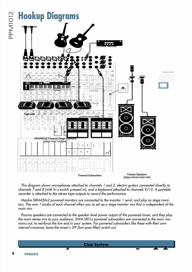
This diagram shows microphones attached to channels 1 and 2, electric guitars connected directly to
channels 7 and 8 (with hi-z switch pressed in), and a keyboard attached to channels 9/10. A portable recorder is attached to the stereo tape outputs to record the performance.
Mackie SRM450v2 powered monitors are connected to the monitor 1 send, and play as stage moni-tors. The mon 1 knobs of each channel allow you to set up a stage monitor mix that is independent of the main mix.
Passive speakers are connected to the speaker-level power output of the powered mixer, and they play the main stereo mix to your audience. SWA1801z powered subwoofers are connected to the main mix mono out, to reinforce the low end in your system. For powered subwoofers like these with their owninternal crossover, leave the mixer's LPF (low-pass-filter) switch out.
2X 800WPROFESSIONALPOWERED
B
SPEAKER OUT
A
SPEAKER OUT
PIN
1+
1
PIN
1+
1
80HzLOW
MIC 1 MIC 2 MIC 3 MIC 4 MIC 5 MIC 6 MIC 7 MIC 8
INPUT
( B AL / UN B AL ) ( B AL / UN BA L ) ( B AL / UN B AL ) ( B AL / UN B AL ) ( B AL / UN B AL ) ( B AL / UN B AL ) ( B AL / UN B AL ) ( B AL / UN B AL )
INSERT INSERT INSERT INSERT INSERT INSERT INSERT INSERT
GAIN
U
-20
LAMP12V0.5A
L
R
FX SEND TAPE
OUTIN
L
MONSEND
FXRTN
(MONO)
MID
FREQ
RL
U
GAIN
M I CG A I N
0 + 50-20dB +30dB
600
1.5k 150
8k 100
O F F M A X
U
GAIN
M I CG A I N
0 + 50-20dB +30dB
U
GAIN
M I CG A I N
0 + 50-20dB +30dB
U
GAIN
M I CG A I N
0 + 50-20dB +30dB
U
GAIN
M I CG A I N
0 + 50-20dB +30dB
U
GAIN
M I CG A I N
0 + 50-20dB +30dB
U
GAIN
M I CG A I N
0 + 50-20dB +30dB
U
GAIN
M I CG A I N
0 + 50-20dB +30dB
1 9/10 11/122 3 4 5 6 7 8
SOLO
OL
+10
0
-20
SOLO
OL
+10
0
-20
1 9/10 11/122 3 4 5 6 7 8
EQ EQ
OFF MAX OFF MAX OFF MAX OFF MAX OFF MAX
12kHzHI
LOWCUT100Hz
U
+15-15U
+15-15U
+15-15
U
+15-15
+20
12kHzHI
80HzLOW
HIMID
2.5kHz
LOW MID
400Hz
U
+15-15U
+15-15U
+15-15
U
+15-15
12kHzHI
80HzLOW
HIMID
2.5kHz
LOW MID
400Hz
GAIN
U
-20
PAN
AUX SEND
EQ
COMP COMP COMP COMP COMP COMP
+20
1
2
L
R
(MONO)L
R
(MONO)L
R
(MONO)
1
2
FXRTN
L
R
L
R
M
L
R
M
MON
1
MON
2
FX
1
FX
2
U
+15 OO
U
+15 OO
U
+15 OO
U
+15 OO
-15
U
+15
-15
U
+15
-15
U
+15
80HzLOW
MID
FREQ
RL
600
1.5k 150
8k 100
EQ
12kHzHI
PAN
AUX SEND
MON
1
MON
2
FX
1
FX
2
U
+15 OO
U
+15 OO
U
+15 OO
U
+15 OO
-15
U
+15
-15
U
+15
-15
U
+15
80HzLOW
MID
FREQ
RL
600
1.5k 150
8k 100
EQ
12kHzHI
PAN
AUX SEND
MON
1
MON
2
FX
1
FX
2
U
+15 OO
U
+15 OO
U
+15 OO
U
+15 OO
-15
U
+15
-15
U
+15
-15
U
+15
80HzLOW
MID
FREQ
RL
600
1.5k 150
8k 100
EQ
12kHzHI
PAN
AUX SEND
MON
1
MON
2
FX
1
FX
2
U
+15 OO
U
+15 OO
U
+15 OO
U
+15 OO
-15
U
+15
-15
U
+15
-15
U
+15
80HzLOW
MID
FREQ
RL
600
1.5k 150
8k 100
EQ
12kHzHI
PAN
AUX SEND
MON
1
MON
2
FX
1
FX
2
U
+15 OO
U
+15 OO
U
+15 OO
U
+15 OO
-15
U
+15
-15
U
+15
-15
U
+15
80HzLOW
MID
FREQ
RL
600
1.5k 150
8k 100
EQ
12kHzHI
PAN
AUX SEND
MON
1
MON
2
FX
1
FX
2
U
+15 OO
U
+15 OO
U
+15 OO
U
+15 OO
-15
U
+15
-15
U
+15
-15
U
+15
80HzLOW
MID
FREQ
RL
600
1.5k 150
8k 100
EQ
12kHzHI
PAN
AUX SEND
MON
1
MON
2
FX
1
FX
2
U
+15 OO
U
+15 OO
U
+15 OO
U
+15 OO
-15
U
+15
-15
U
+15
-15
U
+15
80Hz
LOW
MID
FREQ
RL
600
1.5k 150
8k 100
EQ
12kHz
HI
PAN
AUX SEND
MON
1
MON
2
FX
1
FX
2
U
+15 OO
U
+15 OO
U
+15 OO
U
+15 OO
RL
PAN
AUX SEND
MON
1
MON
2
FX
1
FX
2
U
+15 OO
U
+15 OO
U
+15 OO
U
+15 O O
RL
PAN
AUX SEND
MON
1FX
MON
2
FX
1
FX
2
U
+15 OO
U
+15 OO
U
+15 OO
U
+15 OO
-15
U
+15
-15
U
+15
-15
U
+15
1 FX 2
9 1 210 / INPUT1112 / MAINOUT
MAININSERT
TAPDELAY
INTFX MUTE
TAPDELAY
INTFX MUTE
TAPTOEDIT
01PLATEREVERB
02VOCALPLATE
03WARMROOM
04BRIGHTROOM
13CHORUS
14CHORUS+ REVERB
15DOUBLER
16TAPESLAP
05WARMLOUNGE
06SMALLSTAGE
07WARMTHEATER
08BRIGHTSTAGE
09WARMHALL
10CONCERTHALL
11CATHEDRAL12GATEDREVERB
17DLY1BRIGHT(350ms)
18DLY1WARM(300ms)19DLY2BRIGHT(250ms)20DLY2WARM(200ms)
21DLY3BRIGHT(175ms)22DLY3WARM(150ms)
23CHORUS+DLY(300ms)24REVERB+DLY(200ms)
15
15
10
10
5
5
0
15
15
10
10
5
5
0
16K 8K 4K 2K 1K 50025012563
HI-Z HI-ZOL
4
6
3
10
15
7
10
20
30
0
2
U
+20 OO
TAPE IN
BREAK
MUTESCH 1-12
U
+15 OO
U
+15 OO
TO MON 1 TO MON 2FX 1 FX 1
MONO OUT
LPF
OOMAX
75Hz
100 180
120
200Hz
0dB=0dBu
LEVEL
SET
RUDESOLO
MAINMON2
EQASSIGN
MAINMETERS
RL
PHANTOMPOWER
MAIN EQUALIZER
MON 1 EQUALIZER
15
15
10
10
5
5
0
15
15
10
10
5
5
0
16K 8K 4K 2K 1K 50025012563
SIG/OLSIG/OL
U
+15 OO
SEND MASTER
U
+15 OO
SEND MASTER
LOWCUT100Hz
LOWCUT100Hz
LOWCUT100Hz
LOWCUT100Hz
LOWCUT100Hz
LOWCUT100Hz
LOWCUT100Hz
dB
10
OO
5
5
U
dB
30
20
10
OO
40
50
5
5
U
60
SOLO
OL
+10
0
-20
dB
30
20
10
OO
40
50
5
5
U
60
SOLO
OL
+10
0
-20
dB
30
20
10
OO
40
50
5
5
U
60
SOLO
OL
+10
0
-20
dB
30
20
10
OO
40
50
5
5
U
60
SOLO
OL
+10
0
-20
dB
30
20
10
OO
40
50
5
5
U
60
SOLO
OL
+10
0
-20
dB
30
20
10
OO
40
50
5
5
U
60
SOLO
OL
+10
0
-20
dB
30
20
10
OO
40
50
5
5
U
60
SOLO
OL
+10
0
-20
dB
30
20
10
OO
40
50
5
5
U
60
SOLO
OL
+10
0
-20
dB
30
20
10
OO
40
50
5
5
U
60
SOLO
dB
30
20
10
OO
40
50
5
5
U
60
SOLO
dB
30
20
10
OO
40
50
5
5
U
60
SOLO
dB
30
20
10
OO
40
50
5
5
U
60
SOLO
dB
30
20
10
OO
40
50
5
5
U
60
dB
30
20
10
OO
40
50
5
5
U
60
FXRTN1 FXRTN 2 MON 1 MON 2 MAIN
FOOTSWITCHTIP:FX1
RING:FX2
PHONES
FX
LEVEL
2X 800WPROFESSIONALPOWEREDMIXER
OOMAX
30
20
40
50
60
10 10 10 10 10 10 10 10 10 10 10 10 10 10 10
(L) ( R)
MON1
MON2
MAINS
MON1
STEREOMAIN
A B
LINELINELINELINELINELINELINEHI-Z
LINEHI-Z
POWER AMPLIMITER
A B
POWER AMPMODE
R
Powered Subwoofers
Microphones
press HI-Z buttons
Stereo MainsKeyboard
Passive Speakers(plays stereo main mix)
SRM450v2 Powered Stage Monitors
(plays mon 1 output)
Portable Recorder
AdjustVocal
Compression
(L) (R)
MON 1
MON 2
MAINS
MON 1
STEREOMAIN
A B
POWER AMPMODE
8/22/2019 Mackie PPM1012 12 Channel Powered Mixer Manual
http://slidepdf.com/reader/full/mackie-ppm1012-12-channel-powered-mixer-manual 7/36
.Fne\iËjDXelXc
F ne \i Ë j D Xe l X c
House of Worship
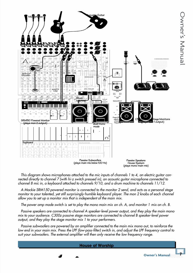
This diagram shows microphones attached to the mic inputs of channels 1 to 4, an electric guitar con-nected directly to channel 7 (with hi-z switch pressed in), an acoustic guitar microphone connected to channel 8 mic in, a keyboard attached to channels 9/10, and a drum machine to channels 11/12.
A Mackie SRM150 powered monitor is connected to the monitor 2 send, and acts as a personal stage monitor to your talented, yet still surprisingly-humble keyboard player. The mon 2 knobs of each channel allow you to set up a monitor mix that is independent of the main mix.
The power amp mode switch is set to play the mono main mix on ch. A, and monitor 1 mix on ch. B.
Passive speakers are connected to channel A speaker-level power output, and they play the main mono mix to your audience. C300z passive stage monitors are connected to channel B speaker-level power output, and they play the stage monitor mix 1 to your performers.
Passive subwoofers are powered by an amplifier connected to the main mix mono out, to reinforce the low end in your main mix. Press the LPF (low-pass-filter) switch in, and adjust the LPF frequency control to suit your subwoofers. The external amplifier will then only receive the low frequency range.
2X 800WPROFESSIONALPOWEREDMIXER
B
SPEAKER OUT
A
SPEAKER OUT
PIN
1+
1
PIN
1+
1
80HzLOW
MIC1 MIC2 MIC3 MIC4 MIC5 MIC6 MIC7 MIC8
INPUT
( B AL / UN B AL ) ( B AL / UN BA L) ( B AL / UN BA L ) ( BA L /U N BA L) ( B AL / UN BA L) ( B AL / UN B AL ) ( B AL / UN BA L) ( B AL / UN BA L)
INSERT I NSER T INSERT INSERT INSERT INSERT INSE RT I NSER T
GAIN
U
-20
LAMP12V0.5A
L
R
FX SEND TAPE
OUTIN
L
MONSEND
FXRTN
(MONO)
MID
FREQ
RL
U
GAIN
M I CG A I N
0 + 50-20dB +30dB
600
1.5k 150
8k 100
OFF MAX
U
GAIN
M I CG A I N
0 + 50-20dB +30dB
U
GAIN
M I CG A I N
0 + 50-20dB +30dB
U
GAIN
M I CG A I N
0 + 50-20dB +30dB
U
GAIN
M I CG A I N
0 + 50-20dB +30dB
U
GAIN
M I CG A I N
0 + 50-20dB +30dB
U
GAIN
M I CG A I N
0 + 50-20dB +30dB
U
GAIN
M I CG A I N
0 + 50-20dB +30dB
1 9/10 11/122 3 4 5 6 7 8
SOLO
OL
+10
0
-20
SOLO
OL
+10
0
-20
1 9/10 11/122 3 4 5 6 7 8
EQ EQ
O FF MAX OFF MAX OF F MAX OFF MAX OF F MAX
12kHzHI
LOWCUT100Hz
U
+15-15
U
+15-15U
+15-15
U
+15-15
+20
12kHz
HI
80HzLOW
HIMID
2.5kHz
LOW MID
400Hz
U
+15-15
U
+15-15U
+15-15
U
+15-15
12kHz
HI
80HzLOW
HIMID
2.5kHz
LOW MID
400Hz
GAIN
U
-20
PAN
AUX SEND
EQ
COMP COMP COMP COMP COMP COMP
+20
1
2
L
R
(MONO)L
R
(MONO)L
R
(MONO)
1
2
FXRTN
L
R
L
R
M
L
R
M
MON
1
MON
2
FX
1
FX
2
U
+15 OO
U
+15 OO
U
+15 OO
U
+15 OO
-15
U
+15
-15
U
+15
-15
U
+15
80HzLOW
MID
FREQ
RL
600
1.5k 150
8k 100
EQ
12kHzHI
PAN
AUX SEND
MON
1
MON
2
FX
1
FX
2
U
+15 OO
U
+15 OO
U
+15 OO
U
+15 OO
-15
U
+15
-15
U
+15
-15
U
+15
80HzLOW
MID
FREQ
RL
600
1.5k 150
8k 100
EQ
12kHzHI
PAN
AUX SEND
MON
1
MON
2
FX
1
FX
2
U
+15 OO
U
+15 OO
U
+15 OO
U
+15 OO
-15
U
+15
-15
U
+15
-15
U
+15
80HzLOW
MID
FREQ
RL
600
1.5k 150
8k 100
EQ
12kHzHI
PAN
AUX SEND
MON
1
MON
2
FX
1
FX
2
U
+15 OO
U
+15 OO
U
+15 OO
U
+15 OO
-15
U
+15
-15
U
+15
-15
U
+15
80HzLOW
MID
FREQ
RL
600
1.5k 150
8k 100
EQ
12kHzHI
PAN
AUX SEND
MON
1
MON
2
FX
1
FX
2
U
+15 OO
U
+15 OO
U
+15 OO
U
+15 OO
-15
U
+15
-15
U
+15
-15
U
+15
80HzLOW
MID
FREQ
RL
600
1.5k 150
8k 100
EQ
12kHzHI
PAN
AUX SEND
MON
1
MON
2
FX
1
FX
2
U
+15 OO
U
+15 OO
U
+15 OO
U
+15 OO
-15
U
+15
-15
U
+15
-15
U
+15
80HzLOW
MID
FREQ
RL
600
1.5k 150
8k 100
EQ
12kHzHI
PAN
AUX SEND
MON
1
MON
2
FX
1
FX
2
U
+15 OO
U
+15 OO
U
+15 OO
U
+15 OO
-15
U
+15
-15
U
+15
-15
U
+15
80HzLOW
MID
FREQ
RL
600
1.5k 150
8k 100
EQ
12kHzHI
PAN
AUX
SEND
MON
1
MON
2
FX
1
FX
2
U
+15 OO
U
+15 OO
U
+15 OO
U
+15 OO
RL
PAN
AUX
SEND
MON
1
MON
2
FX
1
FX
2
U
+15 OO
U
+15 OO
U
+15 OO
U
+15 OO
RL
PAN
AUX
SEND
MON
1FX
MON
2
FX
1
FX
2
U
+15 OO
U
+15 OO
U
+15 OO
U
+15 OO
-15
U
+15
-15
U
+15
-15
U
+15
1 FX 2
9 1 210 / INPUT 1112 / MAINOUT
MAININSERT
TAPDELAY
INTFX MUTE
TAPDELAY
INTFX MUTE
TAPTOEDIT
01PLATEREVERB02VOCALPLATE03WARMROOM04BRIGHTROOM
13CHORUS14CHORUS+ REVERB15DOUBLER16TAPESLAP
05WARMLOUNGE06SMALLSTAGE07WARMTHEATER08BRIGHTSTAGE09WARMHALL10CONCERTHALL11CATHEDRAL12GATEDREVERB
17DLY1 BRIGHT(350ms)18DLY1 WARM(300ms)19DLY2 BRIGHT(250ms)20DLY2 WARM(200ms)21DLY3 BRIGHT(175ms)22DLY3 WARM(150ms)23CHORUS+ DLY(300ms)24REVERB+ DLY(200ms)
15
15
10
10
5
5
0
15
15
10
10
5
5
0
16K 8K 4K 2K 1K 50025012563
HI-Z HI-ZOL
4
6
3
10
15
7
10
20
30
0
2
U
+20 OO
TAPE IN
BREAK
MUTESCH 1-12
U
+15 OO
U
+15 OO
TO MON 1 TO MON 2
FX 1 FX 1MONO OUT
LPF
OOMAX
75Hz
100 180
120
200Hz
0dB=0dBu
LEVELSET
RUDESOLO
MAINMON2
EQASSIGN
MAINMETERS
RL
PHANTOMPOWER
MAIN EQUALIZER
MON 1 EQUALIZER
15
15
10
10
5
5
0
15
15
10
10
5
5
0
16K 8K 4K 2K 1K 50025012563
SIG/OLSIG/OL
U
+15 OO
SEND MASTER
U
+15 OO
SEND MASTER
LOWCUT100Hz
LOWCUT100Hz
LOWCUT100Hz
LOWCUT100Hz
LOWCUT100Hz
LOWCUT100Hz
LOWCUT100Hz
dB
10
OO
5
5
U
dB
30
20
10
OO
40
50
5
5
U
60
SOLO
OL
+10
0
-20
dB
30
20
10
OO
40
50
5
5
U
60
SOLO
OL
+10
0
-20
dB
30
20
10
OO
40
50
5
5
U
60
SOLO
OL
+10
0
-20
dB
30
20
10
OO
40
50
5
5
U
60
SOLO
OL
+10
0
-20
dB
30
20
10
OO
40
50
5
5
U
60
SOLO
OL
+10
0
-20
dB
30
20
10
OO
40
50
5
5
U
60
SOLO
OL
+10
0
-20
dB
30
20
10
OO
40
50
5
5
U
60
SOLO
OL
+10
0
-20
dB
30
20
10
OO
40
50
5
5
U
60
SOLO
OL
+10
0
-20
dB
30
20
10
OO
40
50
5
5
U
60
SOLO
dB
30
20
10
OO
40
50
5
5
U
60
SOLO
dB
30
20
10
OO
40
50
5
5
U
60
SOLO
dB
30
20
10
OO
40
50
5
5
U
60
SOLO
dB
30
20
10
OO
40
50
5
5
U
60
dB
30
20
10
OO
40
50
5
5
U
60
FXRTN 1 FXRTN 2 MON1 MON2 MAIN
FOOTSWITCHTIP:FX1
RING:FX2
PHONES
FX
LEVEL
2X800W PROFESSIONALPOWEREDMIXER
OOMAX
30
20
40
50
60
10 10 10 10 10 10 10 10 10 10 10 10 10 10 10
( L) ( R)
MON1
MON2
MAINS
MON1
STEREOMAIN
A B
LINEHI-Z
LINEHI-Z
POWER AMPLIMITER
A B
POWER AMPMODE
R
LPF
75Hz
100 180
120
200Hz
LINELINELINELINELINELINE
Mains/Mon1
(L) (R)
MON 1
MON 2
MAINS
MON 1
STEREOMAIN
A B
POWER AMPMODE
Microphones
press HI-Z button
Keyboard
Adjust VocalCompression
Press LPF andadjust subcrossover frequency
DrumMachine
Passive SpeakersHouse System
(plays mono main mix)
C300z Passive Stage Monitors(plays mon 1 output)
FRS2800Amplifier
dual-monomode
SRM150 Powered Monitor(plays mon 2 output)
Passive Subwoofers(plays main mix below 100 Hz)
Acoustic Guitarand Mic
8/22/2019 Mackie PPM1012 12 Channel Powered Mixer Manual
http://slidepdf.com/reader/full/mackie-ppm1012-12-channel-powered-mixer-manual 8/36
/ GGD('()
G G D ( ' ( )
DJ System
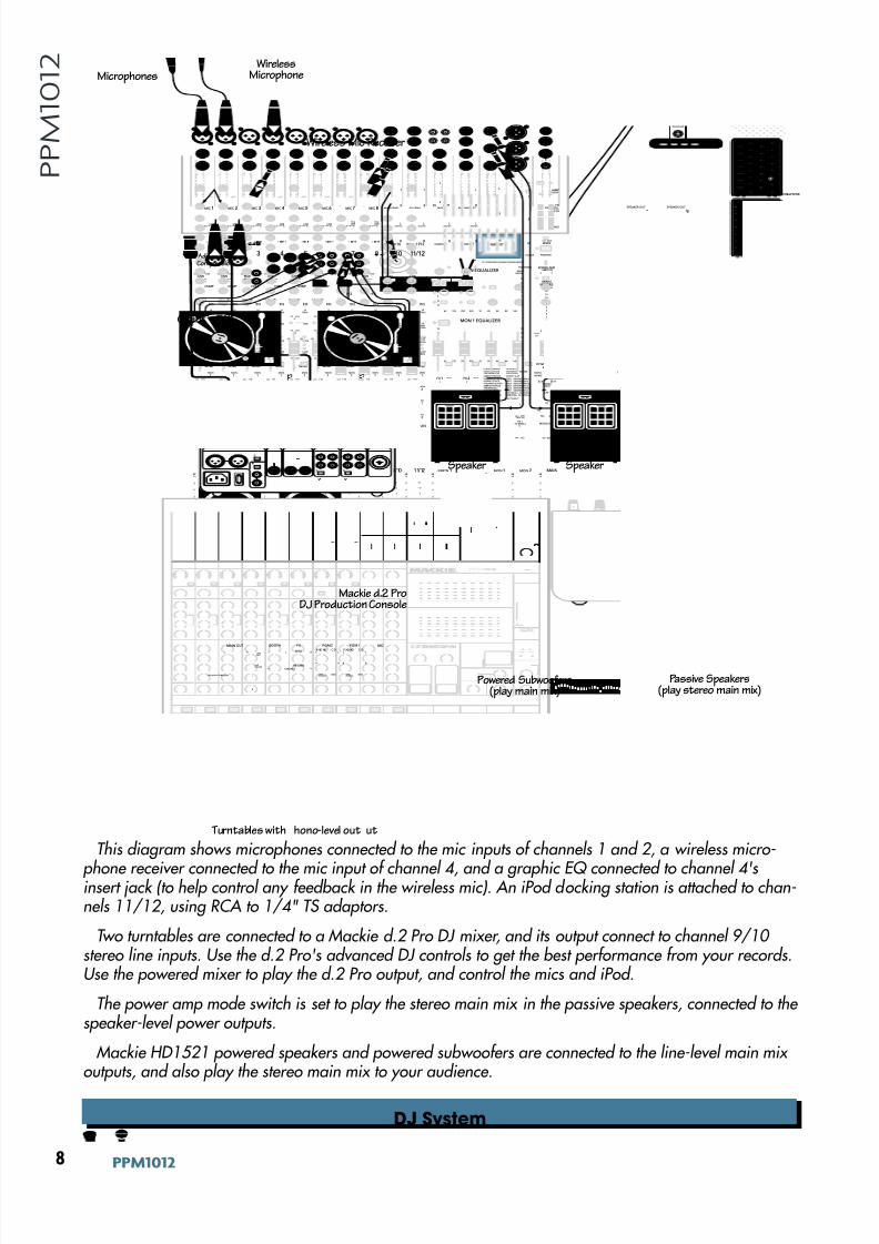
This diagram shows microphones connected to the mic inputs of channels 1 and 2, a wireless micro-
phone receiver connected to the mic input of channel 4, and a graphic EQ connected to channel 4'sinsert jack (to help control any feedback in the wireless mic). An iPod docking station is attached to chan-nels 11/12, using RCA to 1/4" TS adaptors.
Two turntables are connected to a Mackie d.2 Pro DJ mixer, and its output connect to channel 9/10 stereo line inputs. Use the d.2 Pro's advanced DJ controls to get the best performance from your records.Use the powered mixer to play the d.2 Pro output, and control the mics and iPod.
The power amp mode switch is set to play the stereo main mix in the passive speakers, connected to the speaker-level power outputs.
Mackie HD1521 powered speakers and powered subwoofers are connected to the line-level main mix outputs, and also play the stereo main mix to your audience.
2X 800WPROFESSIONALPOWE
B
SPEAKER OUT
A
SPEAKER OUT
PIN
1+
1
PIN
1+
1
80HzLOW
MIC1 MIC 2 MIC3 MIC 4 MIC5 MIC6 MIC7 MIC8
INPUT
( B AL / UN B AL ) ( B AL / UN B AL ) ( B AL / UN B AL ) ( B AL / UN B AL ) ( B AL / UN B AL ) ( B AL / UN B AL ) ( B AL / UN B AL ) ( B AL / UN B AL )
I NSE RT I NSER T I NSE RT I NSER T I NSE RT I NSER T I NSE RT I NSE RT
GAIN
U
-20
LAMP12V0.5A
L
R
FX SEND TAPE
OUTIN
L
MONSEND
FXRTN
(MONO)
MID
FREQ
RL
U
GAIN
M I CG A I N
0 + 50-20dB + 30dB
600
1.5k 150
8k 100
OFF MAX
U
GAIN
M I CG A I N
0 + 50-20dB + 30dB
U
GAIN
M I CG A I N
0 + 50-20dB + 30dB
U
GAIN
M I CG A I N
0 + 50-20dB + 30dB
U
GAIN
M I CG A I N
0 + 50-20dB + 30dB
U
GAIN
M I CG A I N
0 + 50-20dB + 30dB
U
GAIN
M I CG A I N
0 + 50-20dB + 30dB
U
GAIN
M I CG A I N
0 + 50-20dB + 30dB
1 9/10 11/122 3 4 5 6 7 8
SOLO
OL
+10
0
-20
SOLO
OL
+10
0
-20
1 9/10 11/122 3 4 5 6 7 8
EQ EQ
O FF MAX OFF MAX O FF MAX OFF MAX O FF MAX
12kHzHI
LOWCUT100Hz
U
+15-15U
+15-15U
+15-15
U
+15-15
+20
12kHzHI
80HzLOW
HIMID
2.5kHz
LOW MID
400Hz
U
+15-15U
+15-15U
+15-15
U
+15-15
12kHzHI
80HzLOW
HIMID
2.5kHz
LOW MID
400Hz
GAIN
U
-20
PAN
AUX SEND
EQ
COMP COMP COMP COMP COMP COMP
+20
1
2
L
R
(MONO)L
R
(MONO)L
R
(MONO)
1
2
FXRTN
L
R
L
R
M
L
R
M
MON
1
MON
2
FX 1
FX
2
U
+15 OO
U
+15 OO
U
+15 OO
U
+15 OO
-15
U
+15
-15
U
+15
-15
U
+15
80HzLOW
MID
FREQ
RL
600
1.5k 150
8k 100
EQ
12kHzHI
PAN
AUX SEND
MON
1
MON
2
FX 1
FX
2
U
+15 OO
U
+15 OO
U
+15 OO
U
+15 OO
-15
U
+15
-15
U
+15
-15
U
+15
80HzLOW
MID
FREQ
RL
600
1.5k 150
8k 100
EQ
12kHzHI
PAN
AUX SEND
MON
1
MON
2
FX 1
FX
2
U
+15 OO
U
+15 OO
U
+15 OO
U
+15 OO
-15
U
+15
-15
U
+15
-15
U
+15
80HzLOW
MID
FREQ
RL
600
1.5k 150
8k 100
EQ
12kHzHI
PAN
AUX SEND
MON
1
MON
2
FX 1
FX
2
U
+15 OO
U
+15 OO
U
+15 OO
U
+15 OO
-15
U
+15
-15
U
+15
-15
U
+15
80HzLOW
MID
FREQ
RL
600
1.5k 150
8k 100
EQ
12kHzHI
PAN
AUX SEND
MON
1
MON
2
FX 1
FX
2
U
+15 OO
U
+15 OO
U
+15 OO
U
+15 OO
-15
U
+15
-15
U
+15
-15
U
+15
80HzLOW
MID
FREQ
RL
600
1.5k 150
8k 100
EQ
12kHzHI
PAN
AUX SEND
MON
1
MON
2
FX 1
FX
2
U
+15 OO
U
+15 OO
U
+15 OO
U
+15 OO
-15
U
+15
-15
U
+15
-15
U
+15
80HzLOW
MID
FREQ
RL
600
1.5k 150
8k 100
EQ
12kHzHI
PAN
AUX SEND
MON
1
MON
2
FX 1
FX
2
U
+15 OO
U
+15 OO
U
+15 OO
U
+15 OO
-15
U
+15
-15
U
+15
-15
U
+15
80HzLOW
MID
FREQ
RL
600
1.5k 150
8k 100
EQ
12kHz
HI
PAN
AUX SEND
MON
1
MON
2
FX
1
FX
2
U
+15 OO
U
+15 OO
U
+15 OO
U
+15 OO
RL
PAN
AUX SEND
MON
1
MON
2
FX
1
FX
2
U
+15 OO
U
+15 OO
U
+15 OO
U
+15 OO
RL
PAN
AUX SEND
MON
1FX
MON
2
FX
1
FX
2
U
+15 OO
U
+15 OO
U
+15 OO
U
+15 OO
-15
U
+15
-15
U
+15
-15
U
+15
1 FX 2
9 1 210 / INPUT1112 / MAINOUT
MAININSERT
TAPDELAY
INTFX MUTE
TAPDELAY
INTFX MUTE
TAPTOEDIT
01PLATEREVERB02VOCALPLATE03WARMROOM04BRIGHTROOM
13CHORUS14CHORUS+ REVERB15DOUBLER16TAPE SLAP
05WARMLOUNGE06SMALLSTAGE07WARMTHEATER08BRIGHTSTAGE09WARMHALL10CONCERTHALL11CATHEDRAL12GATEDREVERB
17DLY 1BRIGHT(350ms)18DLY 1WARM(300ms)19DLY 2BRIGHT(250ms)20DLY 2WARM(200ms)21DLY 3BRIGHT(175ms)22DLY 3WARM(150ms)23CHORUS+ DLY(300ms)24REVERB+ DLY(200ms)
15
15
10
10
5
5
0
15
15
10
10
5
5
0
16K 8K 4K 2K 1K 50025012563
HI-Z HI-ZOL
4
6
3
10
15
7
10
20
30
0
2
U
+20 OO
TAPE IN
BREAK
MUTESCH 1-12
U
+15 OO
U
+15 OO
TO MON 1 TO MON 2
FX 1 FX 1MONO OUT
LPF
OOMAX
75Hz
100 180
120
200Hz
0dB=0dBu
LEVELSET
RUDESOLO
MAINMON2
EQASSIGN
MAINMETERS
RL
PHANTOMPOWER
MAIN EQUALIZER
MON 1 EQUALIZER
15
15
10
10
5
5
0
15
15
10
10
5
5
0
16K 8K 4K 2K 1K 50025012563
SIG/OLSIG/OL
U
+15 OO
SEND MASTER
U
+15 OO
SEND MASTER
LOWCUT100Hz
LOWCUT100Hz
LOWCUT100Hz
LOWCUT100Hz
LOWCUT100Hz
LOWCUT100Hz
LOWCUT100Hz
dB
10
OO
5
5
U
dB
30
20
10
OO
40
50
5
5
U
60
SOLO
OL
+10
0
-20
dB
30
20
10
OO
40
50
5
5
U
60
SOLO
OL
+10
0
-20
dB
30
20
10
OO
40
50
5
5
U
60
SOLO
OL
+10
0
-20
dB
30
20
10
OO
40
50
5
5
U
60
SOLO
OL
+10
0
-20
dB
30
20
10
OO
40
50
5
5
U
60
SOLO
OL
+10
0
-20
dB
30
20
10
OO
40
50
5
5
U
60
SOLO
OL
+10
0
-20
dB
30
20
10
OO
40
50
5
5
U
60
SOLO
OL
+10
0
-20
dB
30
20
10
OO
40
50
5
5
U
60
SOLO
OL
+10
0
-20
dB
30
20
10
OO
40
50
5
5
U
60
SOLO
dB
30
20
10
OO
40
50
5
5
U
60
SOLO30
20
10
OO
40
50
5
5
U
60
SOLO
dB
30
20
10
OO
40
50
5
5
U
60
SOLO
dB
30
20
10
OO
40
50
5
5
U
60
dB
30
20
10
OO
40
50
5
5
U
60
FXRTN 1 MON1 MON 2 MAIN
FOOTSWITCHTIP:FX1
RING:FX2
PHONES
FX
LEVEL
2X 800WPROFESSIONALPOWEREDMIXER
OOMAX
30
20
40
50
60
10 10 10 10 10 10 10 10 10 10 10 10 10 10 10
( L) ( R)
MON1
MON2
MAINS
MON1
STEREOMAIN
A B
LINEHI-Z
LINEHI-Z
POWER AMPLIMITER
A B
POWER AMPMODE
R
LINELINELINELINELINELINE
Microphones
Adjust VocalCompression
Powered Subwoofers(play main mix)
Passive Speakers(play stereo main mix)
LINEMIC
R R
PGM2MAIN OUT MIC
L LLLL RP HO NO C D
SEND R
BOOTH FX
GNDLINEPHONO
RETURNL(MONO) RR
L
R
LIVERECORD
~100-240VAC50-60Hz20W
PGM1
LINEPHONO
GND
P HO NO C D
R R
LL
Wireless Mic Receiver
Graphic EQ
Turntables with hono-level out ut
Mackie d.2 ProDJ Production Console
iPod® Docking
Station HD1521PoweredSpeaker
HD1521PoweredSpeaker
WirelessMicrophone
Stereo Mains
(L) (R)
MON1
MON2
MAINS
MON1
STEREOMAIN
A B
POWER AMPMODE
8/22/2019 Mackie PPM1012 12 Channel Powered Mixer Manual
http://slidepdf.com/reader/full/mackie-ppm1012-12-channel-powered-mixer-manual 9/36
0Fne\iËjDXelXc
F ne \i Ë j D Xe l X c
Band System
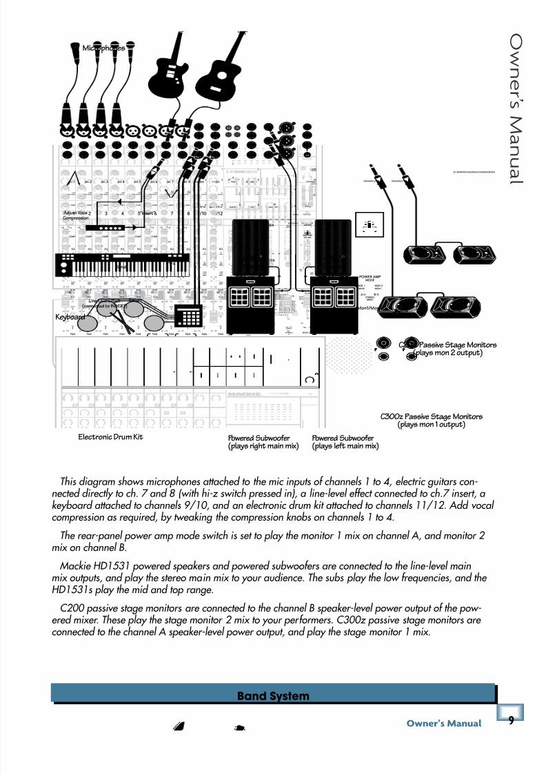
This diagram shows microphones attached to the mic inputs of channels 1 to 4, electric guitars con-nected directly to ch. 7 and 8 (with hi-z switch pressed in), a line-level effect connected to ch.7 insert, a keyboard attached to channels 9/10, and an electronic drum kit attached to channels 11/12. Add vocal compression as required, by tweaking the compression knobs on channels 1 to 4.
The rear-panel power amp mode switch is set to play the monitor 1 mix on channel A, and monitor 2 mix on channel B.
Mackie HD1531 powered speakers and powered subwoofers are connected to the line-level mainmix outputs, and play the stereo main mix to your audience. The subs play the low frequencies, and the HD1531s play the mid and top range.
C200 passive stage monitors are connected to the channel B speaker-level power output of the pow-ered mixer. These play the stage monitor 2 mix to your performers. C300z passive stage monitors are connected to the channel A speaker-level power output, and play the stage monitor 1 mix.
2X 800WPROFESSIONALPOWEREDMIXER
B
SPEAKER OUT
A
SPEAKER OUT
PIN
1+
1
PIN
1+
1
80HzLOW
MIC 1 MIC 2 MIC 3 MIC 4 MIC 5 MIC 6 MIC 7 MIC 8
INPUT
( B AL / UN B AL ) ( B AL / UN B AL ) ( B AL / UN B AL ) ( B AL / UN B AL ) ( B AL / UN B AL ) ( B AL / UN B AL ) ( B AL / UN B AL ) ( B AL / UN B AL )
INSERT INSERT INSERT INSERT INSERT INSERT INSERT INSERT
GAIN
U
-20
LAMP12V0.5A
L
R
FXSEND TAPE
OUTIN
L
MONSEND
FXRTN
(MONO)
MID
FREQ
RL
U
GAIN
M I CG A I N
0 + 50-20dB +30dB
600
1.5k 150
8k 100
O F F M AX
U
GAIN
M I CG A I N
0 + 50-20dB +30dB
U
GAIN
M I CG A I N
0 + 50-20dB +30dB
U
GAIN
M I CG A I N
0 + 50-20dB +30dB
U
GAIN
M I CG A I N
0 + 50-20dB +30dB
U
GAIN
M I CG A I N
0 + 50-20dB +30dB
U
GAIN
M I CG A I N
0 + 50-20dB +30dB
U
GAIN
M I CG A I N
0 + 50-20dB +30dB
1 9/10 11/122 3 4 5 6 7 8
SOLO
OL
+10
0
-20
SOLO
OL
+10
0
-20
1 9/10 11/122 3 4 5 6 7 8
EQ EQ
OFF MAX OFF MAX OFF MAX OFF MAX OFF MAX
12kHzHI
LOWCUT100Hz
U
+15-15U
+15-15U
+15-15
U
+15-15
+20
12kHzHI
80HzLOW
HIMID
2.5kHz
LOW MID
400Hz
U
+15-15U
+15-15U
+15-15
U
+15-15
12kHzHI
80HzLOW
HIMID
2.5kHz
LOW MID
400Hz
GAIN
U
-20
PAN
AUX SEND
EQ
COMP COMP COMP COMP COMP COMP
+20
1
2
L
R
(MONO)L
R
(MONO)L
R
(MONO)
1
2
FXRTN
L
R
L
R
M
L
R
M
MON
1
MON
2
FX
1
FX
2
U
+15 OO
U
+15 OO
U
+15 OO
U
+15 OO
-15
U
+15
-15
U
+15
-15
U
+15
80HzLOW
MID
FREQ
RL
600
1.5k 150
8k 100
EQ
12kHzHI
PAN
AUX SEND
MON
1
MON
2
FX
1
FX
2
U
+15 OO
U
+15 OO
U
+15 OO
U
+15 OO
-15
U
+15
-15
U
+15
-15
U
+15
80HzLOW
MID
FREQ
RL
600
1.5k 150
8k 100
EQ
12kHzHI
PAN
AUX SEND
MON
1
MON
2
FX
1
FX
2
U
+15 OO
U
+15 OO
U
+15 OO
U
+15 OO
-15
U
+15
-15
U
+15
-15
U
+15
80HzLOW
MID
FREQ
RL
600
1.5k 150
8k 100
EQ
12kHzHI
PAN
AUX SEND
MON
1
MON
2
FX
1
FX
2
U
+15 OO
U
+15 OO
U
+15 OO
U
+15 OO
-15
U
+15
-15
U
+15
-15
U
+15
80HzLOW
MID
FREQ
RL
600
1.5k 150
8k 100
EQ
12kHzHI
PAN
AUX SEND
MON
1
MON
2
FX
1
FX
2
U
+15 OO
U
+15 OO
U
+15 OO
U
+15 OO
-15
U
+15
-15
U
+15
-15
U
+15
80HzLOW
MID
FREQ
RL
600
1.5k 150
8k 100
EQ
12kHzHI
PAN
AUX SEND
MON
1
MON
2
FX
1
FX
2
U
+15 OO
U
+15 OO
U
+15 OO
U
+15 OO
-15
U
+15
-15
U
+15
-15
U
+15
80HzLOW
MID
FREQ
RL
600
1.5k 150
8k 100
EQ
12kHzHI
PAN
AUX SEND
MON
1
MON
2
FX
1
FX
2
U
+15 OO
U
+15 OO
U
+15 OO
U
+15 OO
-15
U
+15
-15
U
+15
-15
U
+15
80HzLOW
MID
FREQ
RL
600
1.5k 150
8k 100
EQ
12kHzHI
PAN
AUX SEND
MON
1
MON
2
FX
1
FX
2
U
+15 OO
U
+15 OO
U
+15 OO
U
+15 OO
RL
PAN
AUX SEND
MON
1
MON
2
FX
1
FX
2
U
+15 OO
U
+15 OO
U
+15 OO
U
+15 OO
RL
PAN
AUX SEND
MON
1FX
MON
2
FX
1
FX
2
U
+15 OO
U
+15 OO
U
+15 OO
U
+15 OO
-15
U
+15
-15
U
+15
-15
U
+15
1 FX 2
9 1 210 / INPUT1112 / MAINOUT
MAININSERT
TAPDELAY
INTFX MUTE
TAPDELAY
INTFX MUTE
TAPTOEDIT
01PLATEREVERB02VOCALPLATE
03WARMROOM04BRIGHTROOM
13CHORUS14CHORUS+REVERB
15DOUBLER16TAPESLAP
05WARM LOUNGE06SMALLSTAGE
07WARM THEATER08BRIGHT STAGE
09WARMHALL10CONCERTHALL11CATHEDRAL
12GATEDREVERB
17DLY1BRIGHT(350ms)18DLY1WARM(300ms)
19DLY2BRIGHT(250ms)20DLY2WARM(200ms)
21DLY3BRIGHT(175ms)22DLY3WARM(150ms)23CHORUS+DLY(300ms)
24REVERB+DLY(200ms)
15
15
10
10
5
5
0
15
15
10
10
5
5
0
16K 8K 4K 2K 1K 50025012563
HI-Z HI-ZOL
4
6
3
10
15
7
10
20
30
0
2
U
+20 OO
TAPE IN
BREAK
MUTESCH 1-12
U
+15 OO
U
+15 OO
TO MON 1 TO MON 2FX 1 FX 1
MONO OUT
LPF
OOMAX
75Hz
100 180
120
200Hz
0dB=0dBu
LEVEL
SETRUDESOLO
MAINMON2
EQASSIGN
MAINMETERS
RL
PHANTOMPOWER
MAIN EQUALIZER
MON 1 EQUALIZER
15
15
10
10
5
5
0
15
15
10
10
5
5
0
16K 8K 4K 2K 1K 50025012563
SIG/OLSIG/OL
U
+15 OO
SEND MASTER
U
+15 OO
SEND MASTER
LOWCUT100Hz
LOWCUT100Hz
LOWCUT100Hz
LOWCUT100Hz
LOWCUT100Hz
LOWCUT100Hz
LOWCUT100Hz
dB
10
OO
5
5
U
dB
30
20
10
OO
40
50
5
5
U
60
SOLO
OL
+10
0
-20
dB
30
20
10
OO
40
50
5
5
U
60
SOLO
OL
+10
0
-20
dB
30
20
10
OO
40
50
5
5
U
60
SOLO
OL
+10
0
-20
dB
30
20
10
OO
40
50
5
5
U
60
SOLO
OL
+10
0
-20
dB
30
20
10
OO
40
50
5
5
U
60
SOLO
OL
+10
0
-20
dB
30
20
10
OO
40
50
5
5
U
60
SOLO
OL
+10
0
-20
dB
30
20
10
OO
40
50
5
5
U
60
SOLO
OL
+10
0
-20
dB
30
20
10
OO
40
50
5
5
U
60
SOLO
OL
+10
0
-20
dB
30
20
10
OO
40
50
5
5
U
60
SOLO
dB
30
20
10
OO
40
50
5
5
U
60
SOLO
dB
30
20
10
OO
40
50
5
5
U
60
SOLO
dB
30
20
10
OO
40
50
5
5
U
60
SOLO
dB
30
20
10
OO
40
50
5
5
U
60
dB
30
20
10
OO
40
50
5
5
U
60
FXRTN1 FXRTN 2 MON 1 MON 2 MAIN
FOOTSWITCHTIP:FX1
RING:FX2
PHONES
FX
LEVEL
2X 800WPROFESSIONALPOWEREDMIXER
OOMAX
30
20
40
50
60
10 10 10 10 10 10 10 10 10 10 10 10 10 10 10
(L ) (R )
MON1
MON2
MAINS
MON1
STEREOMAIN
A B
LINEHI-Z
LINEHI-Z
POWER AMPLIMITER
A B
POWER AMPMODE
R
LINELINELINELINELINELINE
Microphones
pressHI-Z
“Insert”
Keyboard
Adjust VocalCompression
C300z Passive Stage Monitors(plays mon 1 output)
C200 Passive Stage Monitors(plays mon 2 output)
Electronic Drum Kit Powered Subwoofer(plays left main mix)
Powered Subwoofer(plays right main mix)
HD1531
PoweredSpeaker
HD1531
PoweredSpeaker
Line-Level Effect(connected to INSERT)
Send
Return
Mon1/Mon2
(L) (R)
MON 1
MON 2
MAINS
MON 1
STEREOMAIN
A B
POWER AMPMODE
8/22/2019 Mackie PPM1012 12 Channel Powered Mixer Manual
http://slidepdf.com/reader/full/mackie-ppm1012-12-channel-powered-mixer-manual 10/36
(' GGD('()
G G D ( ' ( ) PPM1012 Features
Rear Panel
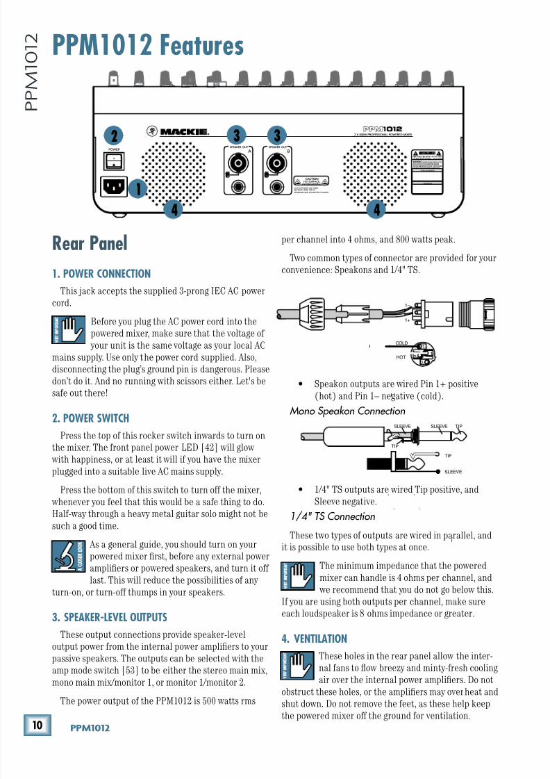
1. POWER CONNECTIONThis jack accepts the supplied 3-prong IEC AC power
cord.
Before you plug the AC power cord into the
powered mixer, make sure that the voltage of
your unit is the same voltage as your local AC
mains supply. Use only the power cord supplied. Also,
disconnecting the plug’s ground pin is dangerous. Please
don’t do it. And no running with scissors either. Let's be
safe out there!
2. POWER SWITCH
Press the top of this rocker switch inwards to turn on
the mixer. The front panel power LED [42] will glow
with happiness, or at least it will if you have the mixer
plugged into a suitable live AC mains supply.
Press the bottom of this switch to turn off the mixer,
whenever you feel that this would be a safe thing to do.
Half-way through a heavy metal guitar solo might not be
such a good time.
As a general guide, you should turn on yourpowered mixer first, before any external power
amplifiers or powered speakers, and turn it off
last. This will reduce the possibilities of any
turn-on, or turn-off thumps in your speakers.
3. SPEAKER-LEVEL OUTPUTS
These output connections provide speaker-level
output power from the internal power amplifiers to your
passive speakers. The outputs can be selected with the
amp mode switch [53] to be either the stereo main mix,
mono main mix/monitor 1, or monitor 1/monitor 2.
The power output of the PPM1012 is 500 watts rms
per channel into 4 ohms, and 800 watts peak.
Two common types of connector are provided for your
convenience: Speakons and 1/4" TS.
• Speakon outputs are wired Pin 1+ positive
(hot) and Pin 1– negative (cold).
Mono Speakon Connection
• 1/4" TS outputs are wired Tip positive, and
Sleeve negative.
1/4" TS Connection
These two types of outputs are wired in parallel, and
it is possible to use both types at once.
The minimum impedance that the powered
mixer can handle is 4 ohms per channel, and
we recommend that you do not go below this.
If you are using both outputs per channel, make sure
each loudspeaker is 8 ohms impedance or greater.
4. VENTILATION
These holes in the rear panel allow the inter-
nal fans to flow breezy and minty-fresh cooling
air over the internal power amplifiers. Do notobstruct these holes, or the amplifiers may overheat and
shut down. Do not remove the feet, as these help keep
the powered mixer off the ground for ventilation.
+ +
T T
I I
I
I
POWER
2 X 800W PROFESSIONAL POWERED MIXER
CAUTIONHOT SURFACE,
AVOID CONTACT REVISION
SERIALNUMBER
WARNING: TO REDUCETHERISK OFFIREORELECTRIC
SHOCK,DO NOTEXPOSETHIS EQUIPMENTTORAIN OR
MOISTURE.DO NOTREMOVECOVER.NO USERSERVICEABLE
PARTS INSIDE.REFERSERVICING TO QUALIFIED PERSONNEL.
AVIS: RISQUE DE CHOC ELECTRIQUE — NE PAS OUVRIR
BSPEAKER OUT
A SPEAKER OUT
OUTPUTPOWER: @4 OHMS,800 WATTS PEAK PER CH
MINIMUMLOAD: 4 OHMS PER CHANNEL
PIN
1+
1
PIN
1+
1
COLD
HOT1+
1+
1–
1–
2–
2+
SLEEVE
TIP
TIPSLEEVE
TIP
SLEEVE
1
4
2 3 3
4
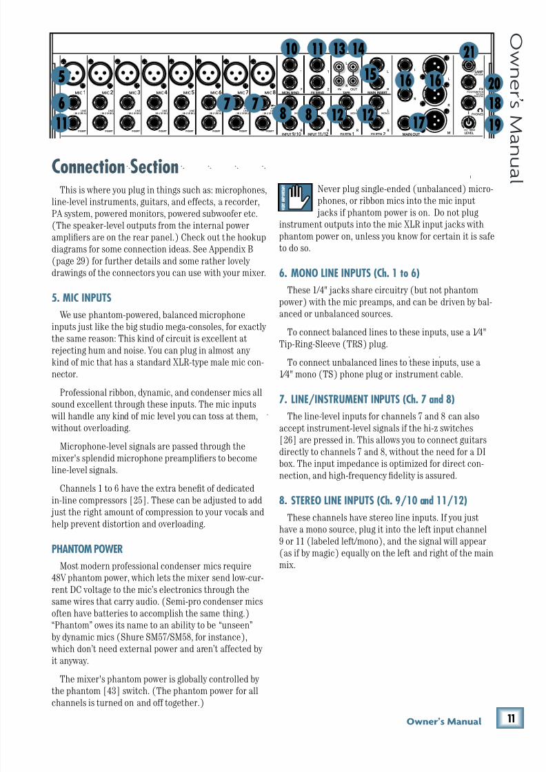
8/22/2019 Mackie PPM1012 12 Channel Powered Mixer Manual
http://slidepdf.com/reader/full/mackie-ppm1012-12-channel-powered-mixer-manual 11/36
((Fne\iËjDXelXc
F ne \i Ë j D Xe l X c
Never plug single-ended (unbalanced) micro-
phones, or ribbon mics into the mic input
jacks if phantom power is on. Do not plug
instrument outputs into the mic XLR input jacks with
phantom power on, unless you know for certain it is safe
to do so.
6. MONO LINE INPUTS (Ch. 1 to 6)These 1/4" jacks share circuitry (but not phantom
power) with the mic preamps, and can be driven by bal-
anced or unbalanced sources.
To connect balanced lines to these inputs, use a 1⁄4"
Tip-Ring-Sleeve (TRS) plug.
To connect unbalanced lines to these inputs, use a
1⁄4" mono (TS) phone plug or instrument cable.
7. LINE/INSTRUMENT INPUTS (Ch. 7 and 8)The line-level inputs for channels 7 and 8 can also
accept instrument-level signals if the hi-z switches
[26] are pressed in. This allows you to connect guitars
directly to channels 7 and 8, without the need for a DI
box. The input impedance is optimized for direct con-
nection, and high-frequency fidelity is assured.
8. STEREO LINE INPUTS (Ch. 9/10 and 11/12)
These channels have stereo line inputs. If you just
have a mono source, plug it into the left input channel
9 or 11 (labeled left/mono), and the signal will appear(as if by magic) equally on the left and right of the main
mix.
Connection SectionThis is where you plug in things such as: microphones,
line-level instruments, guitars, and effects, a recorder,
PA system, powered monitors, powered subwoofer etc.
(The speaker-level outputs from the internal power
amplifiers are on the rear panel.) Check out the hookup
diagrams for some connection ideas. See Appendix B
(page 29) for further details and some rather lovely
drawings of the connectors you can use with your mixer.
5. MIC INPUTS
We use phantom-powered, balanced microphone
inputs just like the big studio mega-consoles, for exactly
the same reason: This kind of circuit is excellent at
rejecting hum and noise. You can plug in almost any
kind of mic that has a standard XLR-type male mic con-
nector.
Professional ribbon, dynamic, and condenser mics all
sound excellent through these inputs. The mic inputs will handle any kind of mic level you can toss at them,
without overloading.
Microphone-level signals are passed through the
mixer's splendid microphone preamplifiers to become
line-level signals.
Channels 1 to 6 have the extra benefit of dedicated
in-line compressors [25]. These can be adjusted to add
just the right amount of compression to your vocals and
help prevent distortion and overloading.
PHANTOM POWER
Most modern professional condenser mics require
48V phantom power, which lets the mixer send low-cur-
rent DC voltage to the mic’s electronics through the
same wires that carry audio. (Semi-pro condenser mics
often have batteries to accomplish the same thing.)
“Phantom” owes its name to an ability to be “unseen”
by dynamic mics (Shure SM57/SM58, for instance),
which don’t need external power and aren’t affected by
it anyway.
The mixer's phantom power is globally controlled by the phantom [43] switch. (The phantom power for all
channels is turned on and off together.)
MIC1 MIC2 MIC3 MIC4 MIC5 MIC 6 MIC 7 MIC 8
INPUT
( BA L/ UNB AL ) ( BA L/ UN BA L) ( BA L/ UN BA L) ( BA L/ UN BA L) ( BA L/ UN BA L) ( BA L/ UNB AL ) ( BA L/ UN BA L) ( BA L/ UN BA L)
INSERT INSERT INSERT INSERT INSERT INSERT INSERT INSERT
LAMP12V 0.5A
L
R
FX SEND TAPE
OUTIN
L
MON SEND
FX RTN
(MONO)
++
++
++
++
++
++
++
++
+ +
1
2
L
R
(MONO)L
R
(MONO)L
R
(MONO)
1
2
FX RTN
L
R
L
R
M
L
R
M
9 1 210 / INPUT 11 12 / MAIN OUT
MAIN INSERT
+ +
I
+ + + + + + + +
FOOTSWITCHTIP:FX1
RING:FX2
PHONES
FX
LEVEL
OOMAX
LINELINELINELINELINELINELINEHI-Z
LINEHI-Z
R
14131110
11
6 7 8 8 12 12
1516
17
16
7
5
21
20
18
19
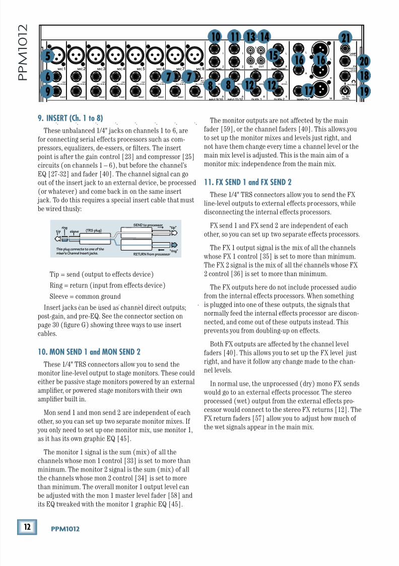
8/22/2019 Mackie PPM1012 12 Channel Powered Mixer Manual
http://slidepdf.com/reader/full/mackie-ppm1012-12-channel-powered-mixer-manual 12/36
() GGD('()
G G D ( ' ( )
The monitor outputs are not affected by the main
fader [59], or the channel faders [40]. This allows you
to set up the monitor mixes and levels just right, and
not have them change every time a channel level or the
main mix level is adjusted. This is the main aim of a
monitor mix: independence from the main mix.
11. FX SEND 1 and FX SEND 2
These 1/4" TRS connectors allow you to send the FXline-level outputs to external effects processors, while
disconnecting the internal effects processors.
FX send 1 and FX send 2 are independent of each
other, so you can set up two separate effects processors.
The FX 1 output signal is the mix of all the channels
whose FX 1 control [35] is set to more than minimum.
The FX 2 signal is the mix of all the channels whose FX
2 control [36] is set to more than minimum.
The FX outputs here do not include processed audio
from the internal effects processors. When somethingis plugged into one of these outputs, the signals that
normally feed the internal effects processor are discon-
nected, and come out of these outputs instead. This
prevents you from doubling-up on effects.
Both FX outputs are affected by the channel level
faders [40]. This allows you to set up the FX level just
right, and have it follow any change made to the chan-
nel levels.
In normal use, the unprocessed (dry) mono FX sends
would go to an external effects processor. The stereo
processed (wet) output from the external effects pro-
cessor would connect to the stereo FX returns [12]. The
FX return faders [57] allow you to adjust how much of
the wet signals appear in the main mix.
9. INSERT (Ch. 1 to 8)
These unbalanced 1/4" jacks on channels 1 to 6, are
for connecting serial effects processors such as com-
pressors, equalizers, de-essers, or filters. The insert
point is after the gain control [23] and compressor [25]
circuits (on channels 1 – 6), but before the channel’s
EQ [27-32] and fader [40]. The channel signal can go
out of the insert jack to an external device, be processed
(or whatever) and come back in on the same insert
jack. To do this requires a special insert cable that mustbe wired thusly:
Tip = send (output to effects device)
Ring = return (input from effects device)
Sleeve = common groundInsert jacks can be used as channel direct outputs;
post-gain, and pre-EQ. See the connector section on
page 30 (figure G) showing three ways to use insert
cables.
10. MON SEND 1 and MON SEND 2
These 1/4" TRS connectors allow you to send the
monitor line-level output to stage monitors. These could
either be passive stage monitors powered by an external
amplifier, or powered stage monitors with their own
amplifier built in.
Mon send 1 and mon send 2 are independent of each
other, so you can set up two separate monitor mixes. If
you only need to set up one monitor mix, use monitor 1,
as it has its own graphic EQ [45].
The monitor 1 signal is the sum (mix) of all the
channels whose mon 1 control [33] is set to more than
minimum. The monitor 2 signal is the sum (mix) of all
the channels whose mon 2 control [34] is set to more
than minimum. The overall monitor 1 output level can
be adjusted with the mon 1 master level fader [58] andits EQ tweaked with the monitor 1 graphic EQ [45].
“tip”
This plug connects to one of themixer’s Channel Insert jacks.
“ring”
tipring
sleeve
SEND to processor
RETURN from processor
(TRS plug)
MIC1 MIC2 MIC3 MIC4 MIC 5 MIC 6 MIC7 MIC8
INPUT
( BA L/ UN BA L) ( BA L/ UN BA L) ( BA L/ UN BA L) ( BA L/ UNB AL ) ( BA L/ UN BA L) ( BA L/ UN BA L) ( BA L/ UN BA L) ( BA L/ UNB AL )
INSERT INSERT INSERT INSERT INSERT INSERT INSERT INSERT
LAMP12V 0.5A
L
R
FX SEND TAPE
OUTIN
L
MON SEND
FX RTN
(MONO)
++
++
++
++
++
++
++
++
+ +
1
2
L
R
(MONO)L
R
(MONO)L
R
(MONO)
1
2
FX RTN
L
R
L
R
M
L
R
M9 1 210 / INPUT 11 12 / MAIN OUT
MAIN INSERT
+ +
I
+ + + + + + + +
FOOTSWITCHTIP:FX1
RING:FX2
PHONES
FX
LEVEL
OOMAX
LINELINELINELINELINELINELINEHI-Z
LINEHI-Z
R
14131110
5
9
6 7 8 8 12 12
1516
17
21
20
18
16
7
19
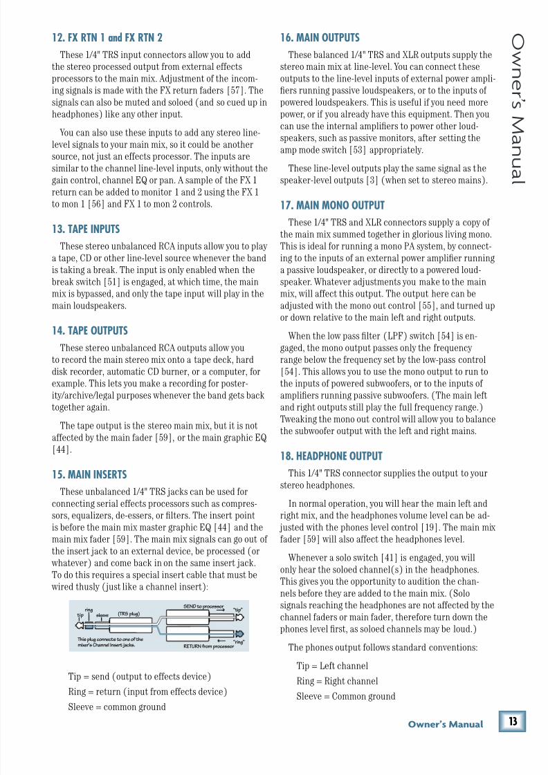
8/22/2019 Mackie PPM1012 12 Channel Powered Mixer Manual
http://slidepdf.com/reader/full/mackie-ppm1012-12-channel-powered-mixer-manual 13/36
(*Fne\iËjDXelXc
F ne \i Ë j D Xe l X c
12. FX RTN 1 and FX RTN 2
These 1/4" TRS input connectors allow you to add
the stereo processed output from external effects
processors to the main mix. Adjustment of the incom-
ing signals is made with the FX return faders [57]. The
signals can also be muted and soloed (and so cued up in
headphones) like any other input.
You can also use these inputs to add any stereo line-level signals to your main mix, so it could be another
source, not just an effects processor. The inputs are
similar to the channel line-level inputs, only without the
gain control, channel EQ or pan. A sample of the FX 1
return can be added to monitor 1 and 2 using the FX 1
to mon 1 [56] and FX 1 to mon 2 controls.
13. TAPE INPUTS
These stereo unbalanced RCA inputs allow you to play
a tape, CD or other line-level source whenever the band
is taking a break. The input is only enabled when thebreak switch [51] is engaged, at which time, the main
mix is bypassed, and only the tape input will play in the
main loudspeakers.
14. TAPE OUTPUTS
These stereo unbalanced RCA outputs allow you
to record the main stereo mix onto a tape deck, hard
disk recorder, automatic CD burner, or a computer, for
example. This lets you make a recording for poster-
ity/archive/legal purposes whenever the band gets back
together again.
The tape output is the stereo main mix, but it is not
affected by the main fader [59], or the main graphic EQ
[44].
15. MAIN INSERTS
These unbalanced 1/4" TRS jacks can be used for
connecting serial effects processors such as compres-
sors, equalizers, de-essers, or filters. The insert point
is before the main mix master graphic EQ [44] and the
main mix fader [59]. The main mix signals can go out of the insert jack to an external device, be processed (or
whatever) and come back in on the same insert jack.
To do this requires a special insert cable that must be
wired thusly (just like a channel insert):
Tip = send (output to effects device)Ring = return (input from effects device)
Sleeve = common ground
16. MAIN OUTPUTS
These balanced 1/4" TRS and XLR outputs supply the
stereo main mix at line-level. You can connect these
outputs to the line-level inputs of external power ampli-
fiers running passive loudspeakers, or to the inputs of
powered loudspeakers. This is useful if you need more
power, or if you already have this equipment. Then you
can use the internal amplifiers to power other loud-
speakers, such as passive monitors, after setting theamp mode switch [53] appropriately.
These line-level outputs play the same signal as the
speaker-level outputs [3] (when set to stereo mains).
17. MAIN MONO OUTPUT
These 1/4" TRS and XLR connectors supply a copy of
the main mix summed together in glorious living mono.
This is ideal for running a mono PA system, by connect-
ing to the inputs of an external power amplifier running
a passive loudspeaker, or directly to a powered loud-speaker. Whatever adjustments you make to the main
mix, will affect this output. The output here can be
adjusted with the mono out control [55], and turned up
or down relative to the main left and right outputs.
When the low pass filter (LPF) switch [54] is en-
gaged, the mono output passes only the frequency
range below the frequency set by the low-pass control
[54]. This allows you to use the mono output to run to
the inputs of powered subwoofers, or to the inputs of
amplifiers running passive subwoofers. (The main left
and right outputs still play the full frequency range.)Tweaking the mono out control will allow you to balance
the subwoofer output with the left and right mains.
18. HEADPHONE OUTPUT
This 1/4" TRS connector supplies the output to your
stereo headphones.
In normal operation, you will hear the main left and
right mix, and the headphones volume level can be ad-
justed with the phones level control [19]. The main mix
fader [59] will also affect the headphones level.Whenever a solo switch [41] is engaged, you will
only hear the soloed channel(s) in the headphones.
This gives you the opportunity to audition the chan-
nels before they are added to the main mix. (Solo
signals reaching the headphones are not affected by the
channel faders or main fader, therefore turn down the
phones level first, as soloed channels may be loud.)
The phones output follows standard conventions:
Tip = Left channel
Ring = Right channel
Sleeve = Common ground
“tip”
This plug connects to one of themixer’s Channel Insert jacks.
“ring”
tipring
sleeve
SEND to processor
RETURN from processor
(TRS plug)
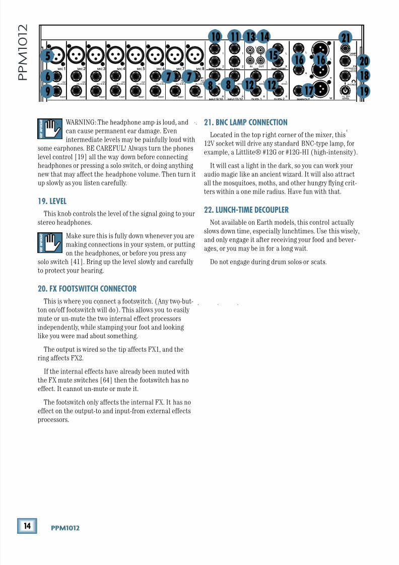
8/22/2019 Mackie PPM1012 12 Channel Powered Mixer Manual
http://slidepdf.com/reader/full/mackie-ppm1012-12-channel-powered-mixer-manual 14/36
(+ GGD('()
G G D ( ' ( )
WARNING: The headphone amp is loud, and
can cause permanent ear damage. Even
intermediate levels may be painfully loud with
some earphones. BE CAREFUL! Always turn the phones
level control [19] all the way down before connecting
headphones or pressing a solo switch, or doing anything
new that may affect the headphone volume. Then turn it
up slowly as you listen carefully.
19. LEVEL
This knob controls the level of the signal going to your
stereo headphones.
Make sure this is fully down whenever you are
making connections in your system, or putting
on the headphones, or before you press any
solo switch [41]. Bring up the level slowly and carefully
to protect your hearing.
20. FX FOOTSWITCH CONNECTOR
This is where you connect a footswitch. (Any two-but-
ton on/off footswitch will do). This allows you to easily
mute or un-mute the two internal effect processors
independently, while stamping your foot and looking
like you were mad about something.
The output is wired so the tip affects FX1, and the
ring affects FX2.
If the internal effects have already been muted with
the FX mute switches [64] then the footswitch has no
effect. It cannot un-mute or mute it.
The footswitch only affects the internal FX. It has no
effect on the output-to and input-from external effects
processors.
MIC1 MIC2 MIC3 MIC4 MIC 5 MIC 6 MIC7 MIC8
INPUT
( BA L/ UN BA L) ( BA L/ UN BA L) ( BA L/ UN BA L) ( BA L/ UNB AL ) ( BA L/ UN BA L) ( BA L/ UN BA L) ( BA L/ UN BA L) ( BA L/ UNB AL )
INSERT INSERT INSERT INSERT INSERT INSERT INSERT INSERT
LAMP12V 0.5A
L
R
FX SEND TAPE
OUTIN
L
MON SEND
FX RTN
(MONO)
++
++
++
++
++
++
++
++
+ +
1
2
L
R
(MONO)L
R
(MONO)L
R
(MONO)
1
2
FX RTN
L
R
L
R
M
L
R
M9 1 210 / INPUT 11 12 / MAIN OUT
MAIN INSERT
+ +
I
+ + + + + + + +
FOOTSWITCHTIP:FX1
RING:FX2
PHONES
FX
LEVEL
OOMAX
LINELINELINELINELINELINELINEHI-Z
LINEHI-Z
R
21. BNC LAMP CONNECTION
Located in the top right corner of the mixer, this
12V socket will drive any standard BNC-type lamp, for
example, a Littlite® #12G or #12G-HI (high-intensity).
It will cast a light in the dark, so you can work your
audio magic like an ancient wizard. It will also attract
all the mosquitoes, moths, and other hungry flying crit-
ters within a one mile radius. Have fun with that.
22. LUNCH-TIME DECOUPLER
Not available on Earth models, this control actually
slows down time, especially lunchtimes. Use this wisely,
and only engage it after receiving your food and bever-
ages, or you may be in for a long wait.
Do not engage during drum solos or scats.
14131110
5
9
6 7 8 8 12 12
1516
17
21
20
18
16
7
19
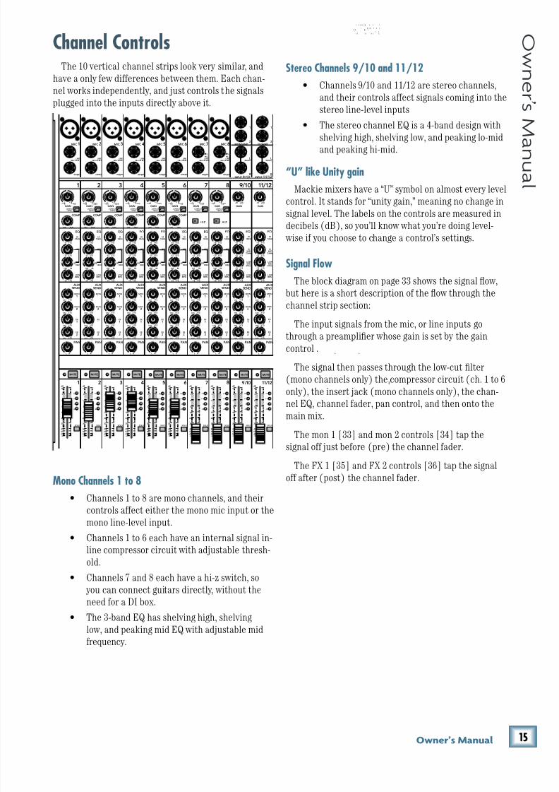
8/22/2019 Mackie PPM1012 12 Channel Powered Mixer Manual
http://slidepdf.com/reader/full/mackie-ppm1012-12-channel-powered-mixer-manual 15/36
(,Fne\iËjDXelXc
F ne \i Ë j D Xe l X c
Channel ControlsThe 10 vertical channel strips look very similar, and
have a only few differences between them. Each chan-
nel works independently, and just controls the signals
plugged into the inputs directly above it.
Mono Channels 1 to 8
• Channels 1 to 8 are mono channels, and their
controls affect either the mono mic input or the
mono line-level input.
• Channels 1 to 6 each have an internal signal in-
line compressor circuit with adjustable thresh-old.
• Channels 7 and 8 each have a hi-z switch, so
you can connect guitars directly, without the
need for a DI box.
• The 3-band EQ has shelving high, shelving
low, and peaking mid EQ with adjustable mid
frequency.
80Hz
LOW
MIC1 MIC2 MIC3 MIC4 MIC 5 MIC 6 MIC 7 MIC 8
INPUT
( BA L/ UN BA L) ( BA L/ UN BA L) ( BA L/ UN BA L) ( BA L/ UN BA L) ( BA L/ UN BA L) ( BA L/ UN BA L) ( BA L/ UN BA L) ( BA L/ UN BA L)
INSERT INSERT INSERT INSERT INSERT INSERT INSERT INSERT
GAIN
U
-20
L
R
FX SENDMON SEND
(MONO)
MID
FREQ
RL
U
GAIN
M I CG A I N
0 + 50-20dB +30dB
600
1.5k 150
8k 100
O FF M AX
U
GAIN
M I CG A I N
0 + 50-20dB +30dB
U
GAIN
M I CG A I N
0 + 50- 2 0d B +3 0d B
U
GAIN
M I CG A I N
0 + 50-20dB +30dB
U
GAIN
M I CG A I N
0 + 50-20dB +30dB
U
GAIN
M I CG A I N
0 + 50- 2 0d B +3 0d B
U
GAIN
M I CG A I N
0 + 50-20dB +30dB
U
GAIN
M I CG A I N
0 + 50-20dB +30dB
1 9/10 11/122 3 4 5 6 7 8
SOLO
OL
+10
0
-20
SOLO
OL
+10
0
-20
1 9/10 11/122 3 4 5 6 7 8
EQ EQ
OFF MAX OFF MAX OFF MAX OFF MAX OFF MAX
12kHzHI
LOWCUT100Hz
U
+15-15U
+15-15U
+15-15
U
+15-15
+20
12kHzHI
80Hz
LOW
HIMID
2.5kHz
LOW MID
400Hz
U
+15-15U
+15-15U
+15-15
U
+15-15
12kHzHI
80Hz
LOW
HIMID
2.5kHz
LOW MID
400Hz
GAIN
U
-20
PAN
AUX SEND
EQ
COMP COMP COMP COMP COMP COMP
+20
1
2
L
R
(MONO)
1
2
MON
1
MON
2
FX
1
FX
2
U
+15 OO
U
+15 OO
U
+15 OO
U
+15 OO
-15
U
+15
-15
U
+15
-15
U
+15
80Hz
LOW
MID
FREQ
RL
600
1.5k 150
8k 100
EQ
12kHzHI
PAN
AUX SEND
MON
1
MON
2
FX
1
FX
2
U
+15 OO
U
+15 OO
U
+15 OO
U
+15 OO
-15
U
+15
-15
U
+15
-15
U
+15
80Hz
LOW
MID
FREQ
RL
600
1.5k 150
8k 100
EQ
12kHzHI
PAN
AUX SEND
MON
1
MON
2
FX
1
FX
2
U
+15 OO
U
+15 OO
U
+15 OO
U
+15 OO
-15
U
+15
-15
U
+15
-15
U
+15
80Hz
LOW
MID
FREQ
RL
600
1.5k 150
8k 100
EQ
12kHzHI
PAN
AUX SEND
MON
1
MON
2
FX
1
FX
2
U
+15 OO
U
+15 OO
U
+15 OO
U
+15 OO
-15
U
+15
-15
U
+15
-15
U
+15
80Hz
LOW
MID
FREQ
RL
600
1.5k 150
8k 100
EQ
12kHzHI
PAN
AUX SEND
MON
1
MON
2
FX
1
FX
2
U
+15 OO
U
+15 OO
U
+15 OO
U
+15 OO
-15
U
+15
-15
U
+15
-15
U
+15
80Hz
LOW
MID
FREQ
RL
600
1.5k 150
8k 100
EQ
12kHzHI
PAN
AUX SEND
MON
1
MON
2
FX
1
FX
2
U
+15 OO
U
+15 OO
U
+15 OO
U
+15 OO
-15
U
+15
-15
U
+15
-15
U
+15
80Hz
LOW
MID
FREQ
RL
600
1.5k 150
8k 100
EQ
12kHzHI
PAN
AUX SEND
MON
1
MON
2
FX
1
FX
2
U
+15 OO
U
+15 OO
U
+15 OO
U
+15 OO
-15
U
+15
-15
U
+15
-15
U
+15
80Hz
LOW
MID
FREQ
RL
600
1.5k 150
8k 100
EQ
12kHzHI
PAN
AUX SEND
MON
1
MON
2
FX
1
FX
2
U
+15 OO
U
+15 OO
U
+15 OO
U
+15 OO
RL
PAN
AUX
SEND
MON
1
MON
2
FX
1
FX
2
U
+15 OO
U
+15 OO
U
+15 OO
U
+15 OO
RL
PAN
AUX
SEND
MON
1
MON
2
FX
1
FX
2
U
+15 OO
U
+15 OO
U
+15 OO
U
+15 OO
-15
U
+15
-15
U
+15
-15
U
+15
9 10 / INPUT 11 12 /
HI-Z HI-Z
+ +
T T
LOWCUT100Hz
LOWCUT100Hz
LOWCUT100Hz
LOWCUT100Hz
LOWCUT100Hz
LOWCUT100Hz
LOWCUT100Hz
dB
10
OO
5
5
U
dB
30
20
10
OO
40
50
5
5
U
60
SOLO
OL
+10
0
-20
dB
30
20
10
OO
40
50
5
5
U
60
SOLO
OL
+10
0
-20
dB
30
20
10
OO
40
50
5
5
U
60
SOLO
OL
+10
0
-20
dB
30
20
10
OO
40
50
5
5
U
60
SOLO
OL
+10
0
-20
dB
30
20
10
OO
40
50
5
5
U
60
SOLO
OL
+10
0
-20
dB
30
20
10
OO
40
50
5
5
U
60
SOLO
OL
+10
0
-20
dB
30
20
10
OO
40
50
5
5
U
60
SOLO
OL
+10
0
-20
dB
30
20
10
OO
40
50
5
5
U
60
SOLO
OL
+10
0
-20
dB
30
20
10
OO
40
50
5
5
U
60
I
30
20
40
50
60
10 10 10 10 10 10 10 10 10 10
LINELINELINELINELINELINELINEHI-Z
LINEHI-Z
: H I K I L I
H K, HI I I
I . . I L
I I . I I LI I L.
I: I E E H E LE I E E I
,
Stereo Channels 9/10 and 11/12
• Channels 9/10 and 11/12 are stereo channels,
and their controls affect signals coming into the
stereo line-level inputs
• The stereo channel EQ is a 4-band design with
shelving high, shelving low, and peaking lo-midand peaking hi-mid.
“U” like Unity gain
Mackie mixers have a “U” symbol on almost every level
control. It stands for “unity gain,” meaning no change in
signal level. The labels on the controls are measured in
decibels (dB), so you’ll know what you’re doing level-
wise if you choose to change a control’s settings.
Signal Flow
The block diagram on page 33 shows the signal flow,but here is a short description of the flow through the
channel strip section:
The input signals from the mic, or line inputs go
through a preamplifier whose gain is set by the gain
control .
The signal then passes through the low-cut filter
(mono channels only) the compressor circuit (ch. 1 to 6
only), the insert jack (mono channels only), the chan-
nel EQ, channel fader, pan control, and then onto the
main mix.
The mon 1 [33] and mon 2 controls [34] tap the
signal off just before (pre) the channel fader.
The FX 1 [35] and FX 2 controls [36] tap the signal
off after (post) the channel fader.
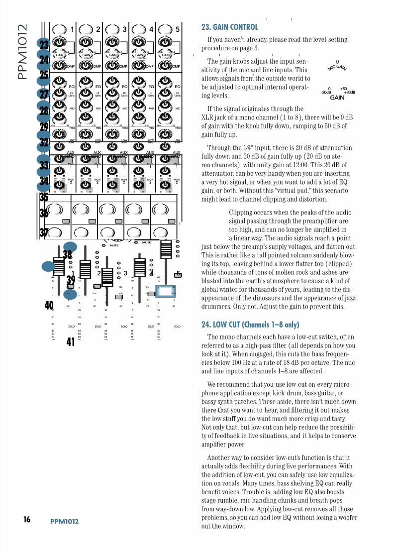
8/22/2019 Mackie PPM1012 12 Channel Powered Mixer Manual
http://slidepdf.com/reader/full/mackie-ppm1012-12-channel-powered-mixer-manual 16/36
(- GGD('()
G G D ( ' ( ) 23. GAIN CONTROL
If you haven’t already, please read the level-setting
procedure on page 3.
The gain knobs adjust the input sen-
sitivity of the mic and line inputs. This
allows signals from the outside world to
be adjusted to optimal internal operat-
ing levels.If the signal originates through the
XLR jack of a mono channel (1 to 8), there will be 0 dB
of gain with the knob fully down, ramping to 50 dB of
gain fully up.
Through the 1⁄4" input, there is 20 dB of attenuation
fully down and 30 dB of gain fully up (20 dB on ste-
reo channels), with unity gain at 12:00. This 20 dB of
attenuation can be very handy when you are inserting
a very hot signal, or when you want to add a lot of EQ
gain, or both. Without this “virtual pad,” this scenario
might lead to channel clipping and distortion.
Clipping occurs when the peaks of the audio
signal passing through the preamplifier are
too high, and can no longer be amplified in
a linear way. The audio signals reach a point
just below the preamp's supply voltages, and flatten out.
This is rather like a tall pointed volcano suddenly blow-
ing its top, leaving behind a lower flatter top (clipped)
while thousands of tons of molten rock and ashes are
blasted into the earth's atmosphere to cause a kind of
global winter for thousands of years, leading to the dis-
appearance of the dinosaurs and the appearance of jazz
drummers. Only not. Adjust the gain to prevent this.
24. LOW CUT (Channels 1–8 only)
The mono channels each have a low-cut switch, often
referred to as a high-pass filter (all depends on how you
look at it). When engaged, this cuts the bass frequen-
cies below 100 Hz at a rate of 18 dB per octave. The mic
and line inputs of channels 1–8 are affected.
We recommend that you use low-cut on every micro-
phone application except kick drum, bass guitar, orbassy synth patches. These aside, there isn’t much down
there that you want to hear, and filtering it out makes
the low stuff you do want much more crisp and tasty.
Not only that, but low-cut can help reduce the possibili-
ty of feedback in live situations, and it helps to conserve
amplifier power.
Another way to consider low-cut’s function is that it
actually adds flexibility during live performances. With
the addition of low-cut, you can safely use low equaliza-
tion on vocals. Many times, bass shelving EQ can really
benefit voices. Trouble is, adding low EQ also boosts
stage rumble, mic handling clunks and breath pops
from way-down low. Applying low-cut removes all those
problems, so you can add low EQ without losing a woofer
out the window.
80HzLOW
I
I
MID
FREQ
RL
U
GAIN
M I C G A I N
0 +50- 20dB +30dB
600
1.5k 150
8k 100
O FF MA X
U
GAIN
M I C G A I N
0 +50- 20dB +30dB
U
GAIN
M I C G A I N
0 +50- 20dB +30dB
U
GAIN
M I C G A I N
0 +50- 20dB +30dB
U
GAIN
M I C G A I N
0 +50- 20dB +30dB
I
I
I
1 2 3 4 5
SOLO
OL
+10
0
-20
SOLO
OL
+10
0
-20
1 2 3 4 5
EQ
OFF MAX OFF MAX OFF MAX OFF MAX
12kHzHI
I
PAN
AUX SEND
COMP COMP COMP COMP COMP
MON
1
MON
2
FX 1
FX
2
U
+15 OO
U
+15 OO
U
+15 OO
U
+15 OO
-15
U
+15
-15
U
+15
-15
U
+15
80HzLOW
MID
FREQ
RL
600
1.5k 150
8k 100
EQ
12kHzHI
PAN
AUX SEND
MON
1
MON
2
FX 1
FX
2
U
+15 OO
U
+15 OO
U
+15 OO
U
+15 OO
-15
U
+15
-15
U
+15
-15
U
+15
80HzLOW
MID
FREQ
RL
600
1.5k 150
8k 100
EQ
12kHzHI
PAN
AUX SEND
MON
1
MON
2
FX 1
FX
2
U
+15 OO
U
+15 OO
U
+15 OO
U
+15 OO
-15
U
+15
-15
U
+15
-15
U
+15
80HzLOW
MID
FREQ
RL
600
1.5k 150
8k 100
EQ
12kHzHI
PAN
AUX SEND
MON
1
MON
2
FX 1
FX
2
U
+15 OO
U
+15 OO
U
+15 OO
U
+15 OO
-15
U
+15
-15
U
+15
-15
U
+15
80HzLOW
MID
FREQ
RL
600
1.5k 150
8k 100
EQ
12kHzHI
PAN
AUX SEND
MON
1
MON
2
FX 1
FX
2
U
+15 OO
U
+15 OO
U
+15 OO
U
+15 OO
-15
U
+15
-15
U
+15
-15
U
+15
I
I I
LOW CUT100 Hz
LOW CUT100 Hz
LOW CUT100 Hz
LOW CUT100 Hz
LOW CUT100 Hz
dB
10
OO
5
5
U
dB
30
20
10
OO
40
50
5
5
U
60
SOLO
OL
+10
0
-20
dB
30
20
10
OO
40
50
5
5
U
60
SOLO
OL
+10
0
-20
dB
30
20
10
OO
40
50
5
5
U
60
SOLO
OL
+10
0
-20
dB
30
20
10
OO
40
50
5
5
U
60
30
20
40
50
60
10 10 10 10 10
U
GAIN
M I C G A I N
0 +50-20dB +30dB
23
24
27
25
28
29
32
33
34
35
36
37
38
40
39
41
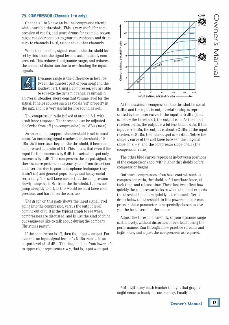
8/22/2019 Mackie PPM1012 12 Channel Powered Mixer Manual
http://slidepdf.com/reader/full/mackie-ppm1012-12-channel-powered-mixer-manual 17/36
(.Fne\iËjDXelXc
F ne \i Ë j D Xe l X c
At the maximum compression, the threshold is set at
0 dBu, and the input to output relationship is repre-
sented by the lower curve. If the input is -5 dBu (thatis, below the threshold), the output is -5. As the input
reaches 0 dBu, the output is a bit less than 0 dBu. If the
input is +5 dBu, the output is about +2 dBu. If the input
reaches +10 dBu, then the output is +3 dBu. Notice the
shapely curve of the soft knee between the diagonal
slope of x = y and the compressor slope of 6:1 (the
compression ratio).
The other blue curves represent in-between positions
of the compressor knob, with higher thresholds before
compression begins.
Outboard compressors often have controls such as
compression ratio, threshold, soft knee/hard knee, at-
tack time, and release time. These last two affect how
quickly the compressor kicks in when the input exceeds
the threshold, and how quickly it is released after it
drops below the threshold. In this powered mixer com-
pressor, these parameters are specially chosen to give
you the best overall performance.
Adjust the threshold carefully, so your dynamic range
is still lovely, without distortion or overload during the
performance. Run through a few practice screams andhigh-notes, and adjust the compression as required.
25. COMPRESSOR (Channels 1–6 only)
Channels 1 to 6 have an in-line compressor circuit
with a variable threshold. This is very useful for com-
pression of vocals, and snare drums for example, so you
might consider connecting your microphones and drum
mics to channels 1 to 6, rather than other channels.
When the incoming signals exceed the threshold level
set by this knob, the signal level is automatically com-pressed. This reduces the dynamic range, and reduces
the chance of distortion due to overloading the input
signals.
Dynamic range is the difference in level be-
tween the quietest part of your song and the
loudest part. Using a compressor, you are able
to squeeze the dynamic range, resulting in
an overall steadier, more constant volume level for the
signal. It helps sources such as vocals "sit" properly in
the mix, and it is very useful for live sound as well.
The compression ratio is fixed at around 6:1, with
a soft knee response. The threshold can be adjusted
clockwise from off (no compression) to 0 dBu (max).
As an example, suppose the threshold is set to maxi-
mum. An incoming signal reaches the threshold of 0
dBu. As it increases beyond the threshold, it becomes
compressed at a ratio of 6:1. This means that even if the
input further increases by 6 dB, the actual output only
increases by 1 dB. This compresses the output signal, so
there is more protection to your system from distortion
and overload due to poor microphone technique (say
it ain't so) and general pops, bangs and heavy metal
screaming. The soft knee means that the compression
slowly ramps up to 6:1 from the threshold. It does not
jump abruptly to 6:1, as this would be hard knee com-
pression, and harder on the ears too.
The graph on this page shows the input signal level
going into the compressor, versus the output level
coming out of it. It is the typical graph to see when
compressors are discussed, and is just the kind of thing
our engineers like to talk about during the company
Christmas party*.If the compressor is off, then the input = output. For
example an input signal level of +5 dBu results in an
output level of +5 dBu. The diagonal line from lower left
to upper right represents x = y, that is, input = output.
+20
-10
-5
+0
+5
+10
+15
+20-10 -5 +0
SLO P E 6: 1
S O F T
K N E E
S L O
P E 1 : 1
+5 +10 +15
INPUT SIGNAL STRENGTH dBu
O U T P U T S I G N A L S T R
E N G T H d
B u
* Mr. Little, my math teacher thought that graphs
might come in handy for me one day. Finally!
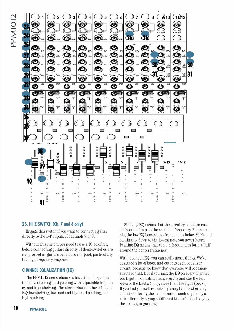
8/22/2019 Mackie PPM1012 12 Channel Powered Mixer Manual
http://slidepdf.com/reader/full/mackie-ppm1012-12-channel-powered-mixer-manual 18/36
(/ GGD('()
G G D ( ' ( )
26. HI-Z SWITCH (Ch. 7 and 8 only)
Engage this switch if you want to connect a guitardirectly to the 1/4" inputs of channels 7 or 8.
Without this switch, you need to use a DI box first,
before connecting guitars directly. If these switches are
not pressed in, guitars will not sound good, particularly
the high frequency response.
CHANNEL EQUALIZATION (EQ)
The PPM1012 mono channels have 3-band equaliza-
tion: low shelving, mid peaking with adjustable frequen-
cy, and high shelving. The stereo channels have 4-band
EQ: low shelving, low-mid and high-mid peaking, and
high shelving.
Shelving EQ means that the circuitry boosts or cuts
all frequencies past the specified frequency. For exam-
ple, the low EQ boosts bass frequencies below 80 Hz and
continuing down to the lowest note you never heard.
Peaking EQ means that certain frequencies form a “hill”
around the center frequency.
With too much EQ, you can really upset things. We’ve
designed a lot of boost and cut into each equalizer
circuit, because we know that everyone will occasion-
ally need that. But if you max the EQ on every channel,
you’ll get mix mush. Equalize subtly and use the left
sides of the knobs (cut), more than the right (boost).
If you find yourself repeatedly using full boost or cut,consider altering the sound source, such as placing a
mic differently, trying a different kind of mic, changing
the strings, or gargling.
80HzLOW
I
GAIN
U
-20
MID
FREQ
RL
U
GAIN
M I C G A I N
0 +50- 20dB +30dB
600
1.5k 150
8k 100
O FF MA X
U
GAIN
M I C G A I N
0 +50- 20dB +30dB
U
GAIN
M I C G A I N
0 +50- 20dB +30dB
U
GAIN
M I C G A I N
0 +50- 20dB +30dB
U
GAIN
M I C G A I N
0 +50- 20dB +30dB
U
GAIN
M I C G A I N
0 +50- 20dB +30dB
U
GAIN
M I C G A I N
0 +50- 20dB +30dB
U
GAIN
M I C G A I N
0 +50- 20dB +30dB
1 9/10 11/122 3 4 5 6 7 8
SOLO
OL
+10
0
-20
SOLO
OL
+10
0
-20
1 9/10 11/122 3 4 5 6 7 8
EQ EQ
OFF MAX OFF MAX OFF MAX OFF MAX OFF MAX
12kHzHI
LOW CUT100 Hz
U
+15-15U
+15-15U
+15-15
U
+15-15
+20
12kHzHI
80HzLOW
HIMID
2.5kHz
LOW MID
400Hz
U
+15-15U
+15-15U
+15-15
U
+15-15
12kHzHI
80HzLOW
HIMID
2.5kHz
LOW MID
400Hz
GAIN
U
-20
PAN
AUX SEND
EQ
COMP COMP COMP COMP COMP COMP
+20
MON
1
MON
2
FX 1
FX
2
U
+15 OO
U
+15 OO
U
+15 OO
U
+15 OO
-15
U
+15
-15
U
+15
-15
U
+15
80HzLOW
MID
FREQ
RL
600
1.5k 150
8k 100
EQ
12kHzHI
PAN
AUX SEND
MON
1
MON
2
FX 1
FX
2
U
+15 OO
U
+15 OO
U
+15 OO
U
+15 OO
-15
U
+15
-15
U
+15
-15
U
+15
80HzLOW
MID
FREQ
RL
600
1.5k 150
8k 100
EQ
12kHzHI
PAN
AUX SEND
MON
1
MON
2
FX 1
FX
2
U
+15 OO
U
+15 OO
U
+15 OO
U
+15 OO
-15
U
+15
-15
U
+15
-15
U
+15
80HzLOW
MID
FREQ
RL
600
1.5k 150
8k 100
EQ
12kHzHI
PAN
AUX SEND
MON
1
MON
2
FX 1
FX
2
U
+15 OO
U
+15 OO
U
+15 OO
U
+15 OO
-15
U
+15
-15
U
+15
-15
U
+15
80HzLOW
MID
FREQ
RL
600
1.5k 150
8k 100
EQ
12kHzHI
PAN
AUX SEND
MON
1
MON
2
FX 1
FX
2
U
+15 OO
U
+15 OO
U
+15 OO
U
+15 OO
-15
U
+15
-15
U
+15
-15
U
+15
80HzLOW
MID
FREQ
RL
600
1.5k 150
8k 100
EQ
12kHzHI
PAN
AUX SEND
MON
1
MON
2
FX 1
FX
2
U
+15 OO
U
+15 OO
U
+15 OO
U
+15 OO
-15
U
+15
-15
U
+15
-15
U
+15
80HzLOW
MID
FREQ
RL
600
1.5k 150
8k 100
EQ
12kHzHI
PAN
AUX SEND
MON
1
MON
2
FX 1
FX
2
U
+15 OO
U
+15 OO
U
+15 OO
U
+15 OO
-15
U
+15
-15
U
+15
-15
U
+15
80HzLOW
MID
FREQ
RL
600
1.5k 150
8k 100
EQ
12kHzHI
PAN
AUX SEND
MON
1
MON
2
FX 1
FX
2
U
+15 OO
U
+15 OO
U
+15 OO
U
+15 OO
RL
PAN
AUX
SEND
MON
1
MON
2
FX 1
FX
2
U
+15 OO
U
+15 OO
U
+15 OO
U
+15 OO
RL
PAN
AUX
SEND
MON
1
MON
2
FX 1
FX
2
U
+15 OO
U
+15 OO
U
+15 OO
U
+15 OO
-15
U
+15
-15
U
+15
-15
U
+15
I
HI-Z HI-Z
LOW CUT100 Hz
LOW CUT100 Hz
LOW CUT100 Hz
LOW CUT100 Hz
LOW CUT100 Hz
LOW CUT100 Hz
LOW CUT100 Hz
dB
10
OO
5
5
U
dB
30
20
10
OO
40
50
5
5
U
60
SOLO
OL
+10
0
-20
dB
30
20
10
OO
40
50
5
5
U
60
SOLO
OL
+10
0
-20
dB
30
20
10
OO
40
50
5
5
U
60
SOLO
OL
+10
0
-20
dB
30
20
10
OO
40
50
5
5
U
60
SOLO
OL
+10
0
-20
dB
30
20
10
OO
40
50
5
5
U
60
SOLO
OL
+10
0
-20
dB
30
20
10
OO
40
50
5
5
U
60
SOLO
OL
+10
0
-20
dB
30
20
10
OO
40
50
5
5
U
60
SOLO
OL
+10
0
-20
dB
30
20
10
OO
40
50
5
5
U
60
SOLO
OL
+10
0
-20
dB
30
20
10
OO
40
50
5
5
U
60
30
20
40
50
60
10 10 10 10 10 10 10 10 10 10
23
24
27
26
25
28
29
32
33
34
35
36
37
30
38
40
39
41
26
30
31 31
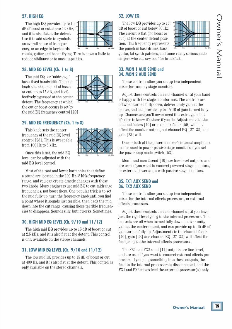
8/22/2019 Mackie PPM1012 12 Channel Powered Mixer Manual
http://slidepdf.com/reader/full/mackie-ppm1012-12-channel-powered-mixer-manual 19/36
(0Fne\iËjDXelXc
F ne \i Ë j D Xe l X c
20Hz 100Hz 1kHz 10kHz 20kHz
–15
–10
–5
0
+5
+10
+15
20Hz 100Hz 1kHz 10kHz 20kHz
–15
–10
–5
0
+5
+10
+15
20Hz 100Hz 1kHz 10kHz 20kHz
–15
–10
–5
0
+5
+10
+15
20Hz 100Hz 1kHz 10kHz 20kHz
–15
–10
–5
0
+5
+10
+15
27. HIGH EQ
The high EQ provides up to 15
dB of boost or cut above 12 kHz,
and it is also flat at the detent.
Use it to add sizzle to cymbals,
an overall sense of transpar-
ency, or an edge to keyboards,
vocals, guitar and bacon frying. Turn it down a little to
reduce sibilance or to mask tape hiss.
28. MID EQ LEVEL (Ch. 1 to 8)
The mid EQ , or “midrange,”
has a fixed bandwidth. The mid
knob sets the amount of boost
or cut, up to 15 dB, and is ef-
fectively bypassed at the center
detent. The frequency at which
the cut or boost occurs is set by
the mid EQ frequency control [29].
29. MID EQ FREQUENCY (Ch. 1 to 8)
This knob sets the center
frequency of the mid EQ level
control [28]. This is sweepable
from 100 Hz to 8 kHz.
Once this is set, the mid EQ
level can be adjusted with the
mid EQ level control.
Most of the root and lower harmonics that definea sound are located in the 100 Hz–8 kHz frequency
range, and you can create drastic changes with these
two knobs. Many engineers use mid EQ to cut midrange
frequencies, not boost them. One popular trick is to set
the mid fully up, turn the frequency knob until you find
a point where it sounds just terrible, then back the mid
down into the cut range, causing those terrible frequen-
cies to disappear. Sounds silly, but it works. Sometimes.
30. HIGH MID EQ LEVEL (Ch. 9/10 and 11/12)
The high mid EQ provides up to 15 dB of boost or cutat 2.5 kHz, and it is also flat at the detent. This control
is only available on the stereo channels.
31. LOW MID EQ LEVEL (Ch. 9/10 and 11/12)
The low mid EQ provides up to 15 dB of boost or cut
at 400 Hz, and it is also flat at the detent. This control is
only available on the stereo channels.
32. LOW EQ
The low EQ provides up to 15
dB of boost or cut below 80 Hz.
The circuit is flat (no boost or
cut) at the center detent posi-
tion. This frequency represents
the punch in bass drums, bass
guitar, fat synth patches, and some really serious male
singers who eat raw beef for breakfast.
33. MON 1 AUX SEND and34. MON 2 AUX SEND
These controls allow you set up two independent
mixes for running stage monitors.
Adjust these controls on each channel until your band
is happy with the stage monitor mix. The controls are
off when turned fully down, deliver unity gain at the
center, and can provide up to 15 dB of gain turned fully
up. Chances are you’ll never need this extra gain, butit’s nice to know it’s there if you do. Adjustments to the
channel faders [40] or main mix fader [59] will not
affect the monitor output, but channel EQ [27–32] and
gain [23] will.
One or both of the powered mixer's internal amplifiers
can be used to power passive stage monitors if you set
the power amp mode switch [53].
Mon 1 and mon 2 send [10] are line-level outputs, and
are used if you want to connect powered stage monitors,
or external power amps with passive stage monitors.
35. FX1 AUX SEND and36. FX2 AUX SEND
These controls allow you set up two independent
mixes for the internal effects processors, or external
effects processors.
Adjust these controls on each channel until you have
just the right level going to the internal processors. The
controls are off when turned fully down, deliver unity
gain at the center detent, and can provide up to 15 dB of
gain turned fully up. Adjustments to the channel fader[40], gain [23] and channel EQ [27–32] will affect the
feed going to the internal effects processors.
The FX1 and FX2 send [11] outputs are line-level,
and are used if you want to connect external effects pro-
cessors. If you plug something into these outputs, the
feed to the internal processors is disconnected, and the
FX1 and FX2 mixes feed the external processor(s) only.
8/22/2019 Mackie PPM1012 12 Channel Powered Mixer Manual
http://slidepdf.com/reader/full/mackie-ppm1012-12-channel-powered-mixer-manual 20/36
)' GGD('()
G G D ( ' ( ) 37. PAN
For the mono channels (1 to 8) this control allows you
to adjust how much of the channel signal goes to the
left main mix, and how much goes to the right main mix.
It has no effect on the aux, as these are mono. In the
center position, the mono channel is split equally to the
left and right.
For the stereo channels (9/10 and 11/12), pan acts ina similar way to a home stereo balance control.
If you have a stereo source and the mixer's stereo
inputs are already taken, connect the source's left out-
put into one mono channel, and the right into another.
Pan the first one fully left, and the second channel fully
right, then the source will appear in the main mix in full
stereo.
38. MUTE switch and LED
The mute switch cuts the signal from the channel
from reaching the main mix bus and the aux busses. The
LED acts as a reminder of its on-ness.
The mute switches near the FX RTN 1 and FX RTN 2
faders will stop the signals from the internal effects (or
any external effects) from reaching the main mix, or
monitor 1 or monitor 2.
39. –20, 0, +10, OL CHANNEL METER LEDs
The OL (overload) LED will come on when the chan-
nel’s input signal is too high. This should be avoided, as
distortion will occur.
If the OL LED is coming on regularly, check that the
gain control [23] is set correctly for your input device,
and that the channel EQ [27–32] is not set with too
much boost.
The –20, 0, and +10 LEDs show the channel signal
strength.
40. CHANNEL FADER
The channel faders adjust the level of each channel
onto the main mix. The “U” mark indicates unity gain,meaning no increase or decrease of signal level. All the
way up provides an additional 10 dB, should you need
to boost a section of a song. If you find that the overall
level is too quiet or too loud with the level near unity,
check that the gain control [23] is set correctly.
41. SOLO
Whenever a solo switch is engaged, you will only hear
the soloed channel(s) in the headphones. This gives you
the opportunity to audition the channels before they are
added to the main mix.
You can also use solo to set the gain of each channel
correctly. When a channel is soled, you can adjust the
channel gain [23] until your input source reaches thelevel of the 0 dB LED of the main meters [48].
Solo signals reaching the headphones are not
affected by the channel faders or main fader,
therefore turn down the phones level [19]
first, as soloed channels may be loud.
The rude solo light [49] will turn on as a reminder
that what you are listening to in the headphones is just
the soloed channel(s).
For stereo channels, the mono sum of the left and
right are heard in the headphones and the level seen onthe left meter.
The output from the FX processors can also be soled
and auditioned, as can the output to monitor 1 and
monitor 2.
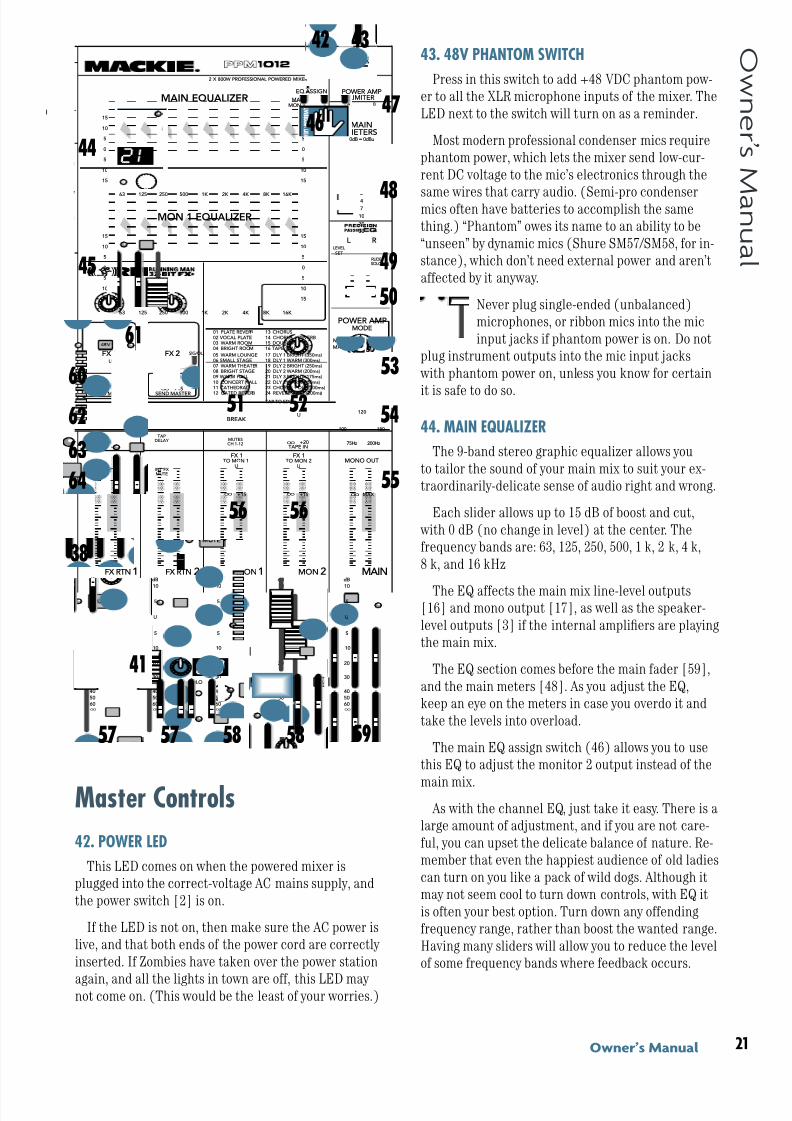
8/22/2019 Mackie PPM1012 12 Channel Powered Mixer Manual
http://slidepdf.com/reader/full/mackie-ppm1012-12-channel-powered-mixer-manual 21/36
)(Fne\iËjDXelXc
F ne \i Ë j D Xe l X c
43. 48V PHANTOM SWITCH
Press in this switch to add +48 VDC phantom pow-
er to all the XLR microphone inputs of the mixer. The
LED next to the switch will turn on as a reminder.
Most modern professional condenser mics require
phantom power, which lets the mixer send low-cur-
rent DC voltage to the mic’s electronics through the
same wires that carry audio. (Semi-pro condensermics often have batteries to accomplish the same
thing.) “Phantom” owes its name to an ability to be
“unseen” by dynamic mics (Shure SM57/SM58, for in-
stance), which don’t need external power and aren’t
affected by it anyway.
Never plug single-ended (unbalanced)
microphones, or ribbon mics into the mic
input jacks if phantom power is on. Do not
plug instrument outputs into the mic input jacks
with phantom power on, unless you know for certain
it is safe to do so.
44. MAIN EQUALIZER
The 9-band stereo graphic equalizer allows you
to tailor the sound of your main mix to suit your ex-
traordinarily-delicate sense of audio right and wrong.
Each slider allows up to 15 dB of boost and cut,
with 0 dB (no change in level) at the center. The
frequency bands are: 63, 125, 250, 500, 1 k, 2 k, 4 k,
8 k, and 16 kHz
The EQ affects the main mix line-level outputs[16] and mono output [17], as well as the speaker-
level outputs [3] if the internal amplifiers are playing
the main mix.
The EQ section comes before the main fader [59],
and the main meters [48]. As you adjust the EQ,
keep an eye on the meters in case you overdo it and
take the levels into overload.
The main EQ assign switch (46) allows you to use
this EQ to adjust the monitor 2 output instead of the
main mix. As with the channel EQ, just take it easy. There is a
large amount of adjustment, and if you are not care-
ful, you can upset the delicate balance of nature. Re-
member that even the happiest audience of old ladies
can turn on you like a pack of wild dogs. Although it
may not seem cool to turn down controls, with EQ it
is often your best option. Turn down any offending
frequency range, rather than boost the wanted range.
Having many sliders will allow you to reduce the level
of some frequency bands where feedback occurs.
Master Controls
42. POWER LED
This LED comes on when the powered mixer is
plugged into the correct-voltage AC mains supply, and
the power switch [2] is on.
If the LED is not on, then make sure the AC power is
live, and that both ends of the power cord are correctly
inserted. If Zombies have taken over the power station
again, and all the lights in town are off, this LED may not come on. (This would be the least of your worries.)
I
FX 1 FX 2
TAPDELAY
INT FX MUTE
TAPDELAY
INT FX MUTE
TAP TO EDIT
01 PLATE REVERB
02 VOCAL PLATE03 WARM ROOM04 BRIGHT ROOM
13 CHORUS
14 CHORUS + REVERB15 DOUBLER16 TAPE SLAP
05 WARM LOUNGE06 SMALL STAGE07 WARM THEATER08 BRIGHT STAGE09 WARM HALL
10 CONCERT HALL11 CATHEDRAL
12 GATED REVERB
17 DLY 1 BRIGHT (350ms)18 DLY 1 WARM (300ms)19 DLY 2 BRIGHT (250ms)20 DLY 2 WARM (200ms)21 DLY 3 BRIGHT (175ms)
22 DLY 3 WARM (150ms)23 CHORUS + DLY (300ms)
24 REVERB + DLY (200ms)
15
15
10
10
5
5
0
15
15
10
10
5
5
0
16K 8K 4K 2K 1K 50025012563
OL
4
6
3
10
15
7
10
20
30
0
2
U
+20 OO
TAPE IN
BREAK
MUTESCH 1-12
U
+15 OO
U
+15 OO
TO MON 1 TO MON 2
FX 1 FX 1MONO OUT
LPF
OOMAX
75Hz
100 180
120
200Hz
0dB = 0dBu
LEVEL
SET
RUDESOLO
MAINMON 2
EQ ASSIGN
MAINMETERS
RL
PHANTOMPOWER
MAIN EQUALIZER
MON 1 EQUALIZER
15
15
10
10
5
5
0
15
15
10
10
5
5
0
16K 8K 4K 2K 1K 50025012563
SIG/OLSIG/OL
U
+15 OO
SEND MASTER
U
+15 OO
SEND MASTER
SOLO
dB
30
20
10
OO
40
50
5
5
U
60
SOLO
dB
30
20
10
OO
40
50
5
5
U
60
SOLO
dB
30
20
10
OO
40
50
5
5
U
60
SOLO
dB
30
20
10
OO
40
50
5
5
U
60
dB
30
20
10
OO
40
50
5
5
U
60
FX RTN 1 FX RTN 2 MON1 MON 2 MAIN
2 X 800W PROFESSIONAL POWERED MIXER
10 10 10 10 10
(L) (R)
MON 1
MON 2
MAINS
MON 1
STEREOMAIN
A B
POWER AMPLIMITER
A B
POWER AMPMODE
53
54
55
52 51
56
60
62
63
64
61
59 57 58 57 58
56
42 43
44
45
4647
49
50
48
41
38
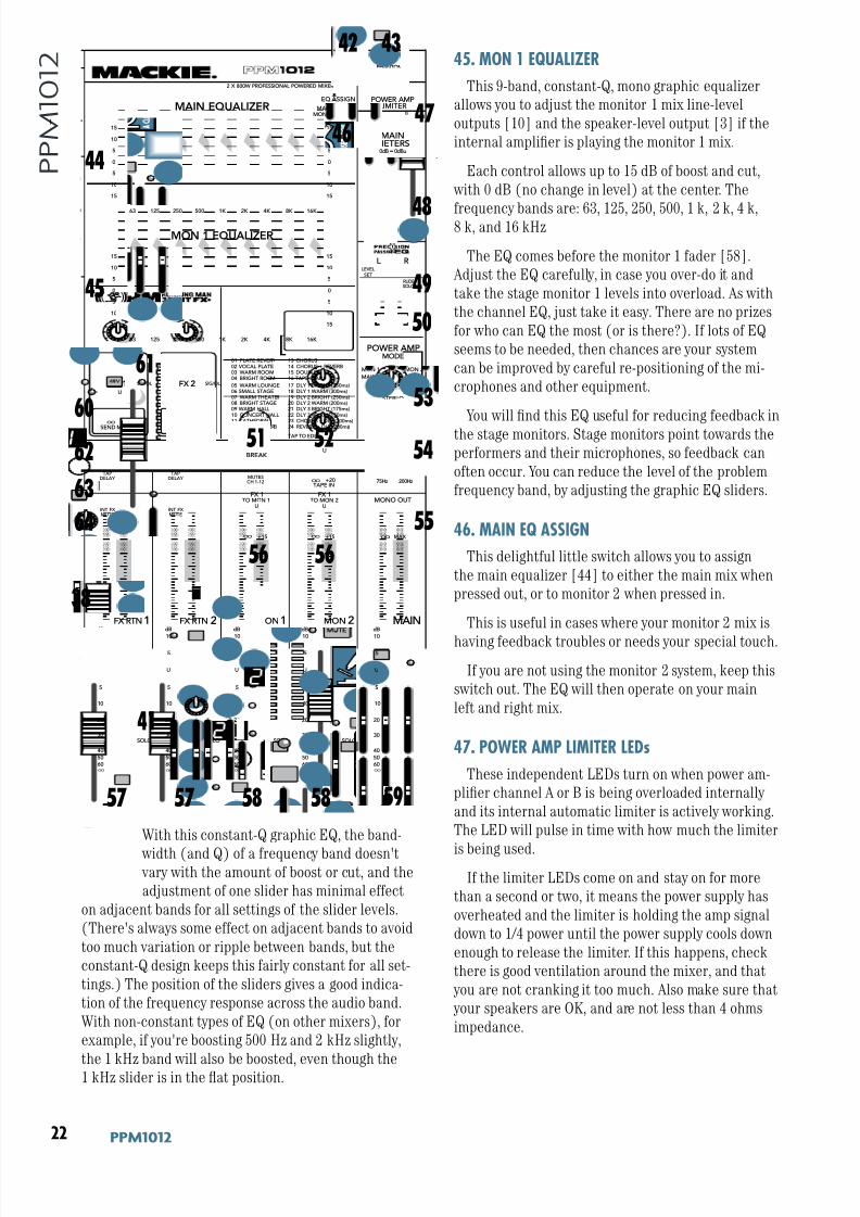
8/22/2019 Mackie PPM1012 12 Channel Powered Mixer Manual
http://slidepdf.com/reader/full/mackie-ppm1012-12-channel-powered-mixer-manual 22/36
)) GGD('()
G G D ( ' ( )
With this constant-Q graphic EQ, the band-
width (and Q) of a frequency band doesn't vary with the amount of boost or cut, and the
adjustment of one slider has minimal effect
on adjacent bands for all settings of the slider levels.
(There's always some effect on adjacent bands to avoid
too much variation or ripple between bands, but the
constant-Q design keeps this fairly constant for all set-
tings.) The position of the sliders gives a good indica-
tion of the frequency response across the audio band.
With non-constant types of EQ (on other mixers), for
example, if you're boosting 500 Hz and 2 kHz slightly,
the 1 kHz band will also be boosted, even though the1 kHz slider is in the flat position.
45. MON 1 EQUALIZER
This 9-band, constant-Q, mono graphic equalizer
allows you to adjust the monitor 1 mix line-level
outputs [10] and the speaker-level output [3] if the
internal amplifier is playing the monitor 1 mix.
Each control allows up to 15 dB of boost and cut,
with 0 dB (no change in level) at the center. The
frequency bands are: 63, 125, 250, 500, 1 k, 2 k, 4 k,8 k, and 16 kHz
The EQ comes before the monitor 1 fader [58].
Adjust the EQ carefully, in case you over-do it and
take the stage monitor 1 levels into overload. As with
the channel EQ, just take it easy. There are no prizes
for who can EQ the most (or is there?). If lots of EQ
seems to be needed, then chances are your system
can be improved by careful re-positioning of the mi-
crophones and other equipment.
You will find this EQ useful for reducing feedback in
the stage monitors. Stage monitors point towards the
performers and their microphones, so feedback can
often occur. You can reduce the level of the problem
frequency band, by adjusting the graphic EQ sliders.
46. MAIN EQ ASSIGN
This delightful little switch allows you to assign
the main equalizer [44] to either the main mix when
pressed out, or to monitor 2 when pressed in.
This is useful in cases where your monitor 2 mix is
having feedback troubles or needs your special touch.
If you are not using the monitor 2 system, keep this
switch out. The EQ will then operate on your main
left and right mix.
47. POWER AMP LIMITER LEDs
These independent LEDs turn on when power am-
plifier channel A or B is being overloaded internally
and its internal automatic limiter is actively working.
The LED will pulse in time with how much the limiter
is being used.If the limiter LEDs come on and stay on for more
than a second or two, it means the power supply has
overheated and the limiter is holding the amp signal
down to 1/4 power until the power supply cools down
enough to release the limiter. If this happens, check
there is good ventilation around the mixer, and that
you are not cranking it too much. Also make sure that
your speakers are OK, and are not less than 4 ohms
impedance.
I
FX 1 FX 2
TAPDELAY
INT FX MUTE
TAPDELAY
INT FX MUTE
TAP TO EDIT
01 PLATE REVERB
02 VOCAL PLATE03 WARM ROOM04 BRIGHT ROOM
13 CHORUS
14 CHORUS + REVERB15 DOUBLER16 TAPE SLAP
05 WARM LOUNGE06 SMALL STAGE07 WARM THEATER08 BRIGHT STAGE09 WARM HALL
10 CONCERT HALL11 CATHEDRAL
12 GATED REVERB
17 DLY 1 BRIGHT (350ms)18 DLY 1 WARM (300ms)19 DLY 2 BRIGHT (250ms)20 DLY 2 WARM (200ms)21 DLY 3 BRIGHT (175ms)
22 DLY 3 WARM (150ms)23 CHORUS + DLY (300ms)
24 REVERB + DLY (200ms)
15
15
10
10
5
5
0
15
15
10
10
5
5
0
16K 8K 4K 2K 1K 50025012563
OL
4
6
3
10
15
7
10
20
30
0
2
U
+20 OO
TAPE IN
BREAK
MUTESCH 1-12
U
+15 OO
U
+15 OO
TO MON 1 TO MON 2
FX 1 FX 1MONO OUT
LPF
OOMAX
75Hz
100 180
120
200Hz
0dB = 0dBu
LEVEL
SET
RUDESOLO
MAINMON 2
EQ ASSIGN
MAINMETERS
RL
PHANTOMPOWER
MAIN EQUALIZER
MON 1 EQUALIZER
15
15
10
10
5
5
0
15
15
10
10
5
5
0
16K 8K 4K 2K 1K 50025012563
SIG/OLSIG/OL
U
+15 OO
SEND MASTER
U
+15 OO
SEND MASTER
SOLO
dB
30
20
10
OO
40
50
5
5
U
60
SOLO
dB
30
20
10
OO
40
50
5
5
U
60
SOLO
dB
30
20
10
OO
40
50
5
5
U
60
SOLO
dB
30
20
10
OO
40
50
5
5
U
60
dB
30
20
10
OO
40
50
5
5
U
60
FX RTN 1 FX RTN 2 MON1 MON 2 MAIN
2 X 800W PROFESSIONAL POWERED MIXER
10 10 10 10 10
(L) (R)
MON 1
MON 2
MAINS
MON 1
STEREOMAIN
A B
POWER AMPLIMITER
A B
POWER AMPMODE
53
54
55
52 51
56
60
62
63
64
61
59 57 58 57 58
56
42 43
44
45
4647
49
50
48
38
41
8/22/2019 Mackie PPM1012 12 Channel Powered Mixer Manual
http://slidepdf.com/reader/full/mackie-ppm1012-12-channel-powered-mixer-manual 23/36
)*Fne\iËjDXelXc
F ne \i Ë j D Xe l X c
48. MAIN MIX METERS
Developed from professional hamster drag-racing as-
sociation (PHDRA) starting lights, these stereo meters
show the level of the left and right main mix, after the
main fader [59] and graphic EQ [44] sections.
The top LEDs are marked OL (overload), and you
should adjust the levels to avoid these coming on too of-
ten, if at all. Check the levels after changing the graphicEQ, the main fader, or any channel settings.
When a channel is soloed, the left meter indicates the
soloed channel level, and the 0 dB mark shows the op-
timum level for adjustment of the channel gain control.
See page 3 for details.
Please remember: Audio meter displays are
just tools to help assure you that your levels
are “in the ballpark.” You don’t have to stare at
them (unless you want to).
49. RUDE SOLO LIGHT
This rather impertinent LED will light whenever a
solo button [41] is pressed. This acts as a reminder that
one or more channels is soloed, so the headphones play
one or more soloed channels, and the left meter [48]
indicates the soloed level, not the main mix level.
50. PRECISION PASSIVE EQ
If you are using Mackie passive speakers such as the
C200, C300z, S215, and S225, then press this switch in
for enhanced clarity and low-frequency response. If you are not using Mackie speakers, then press it and
listen for any improvement. The passive EQ circuit is
added just before the internal power amplifiers, so only
loudspeakers connected to the rear panel speaker-level
outputs [3] will be affected.
51. BREAK SWITCH and LED
This important "take-a-break" switch quickly discon-
nects the main mix from playing in the main loudspeak-
ers [3] and line-level outputs [16, 17], and allows the
tape input [13] to play instead. For example, you couldplay a soothing CD to restore order while the band is
hiding, and before the police arrive. As the audience
is trashing the stage, there will be no upsetting micro-
phone yells, noise, thumps or rumbles heard in the main
speakers.
The monitor 1 and monitor 2 outputs are not affected
by the break switch, so you could turn down the monitor
faders [58] if needed.
The break LED will come on as a reminder that the
break switch is engaged. Check this LED first, if you arenot hearing any sound in your system.
Use the nearby tape in control [52] to turn up the
level of the tape input to play in your system during the
break(age).
52. TAPE IN
When the break switch [51] is pressed in, this knob
allows you to turn up the level of the tape input. This
will then play in your main system instead of the main
mix. Fully down is off, U is unity gain, and fully up gives20 dB of gain.
Keep this control fully down, until a break is required,
then press the break switch and carefully bring up the
level, while you play the tape or CD.
Any line-level source can be connected to the tape
inputs [13], including iPod docks, CD/DVD players and
so forth.
53. POWER AMP MODE SWITCH
This three-position switch lets you choose which
signal paths from the mixer section are sent to the
internal power amplifiers. This allows considerable flex-
ibility in the use of the powered mixer. For example, if
you already have powered main loudspeakers, you could
use the PPM1012 power amplifiers to run passive stage
monitors.
Stereo Mains
The output from channel A is the left side of
the main mix, and the output from channel Bis the right side of the main mix. Choose this
position to play a straight stereo show.
Mains/Monitor 1
Channel A is the mono main mix, and channel
B is the monitor 1 mix. In this setup, you could
run a mono PA system on one channel, and a
passive stage monitor on the other.
Monitor 1/Monitor 2
Channel A is the monitor 1 mix, and channel Bis the monitor 2 mix. In this setup, the internal
power amplifiers could power two passive stage
monitors (or sets of monitors).
Note: This switch does not affect any line
level output, it just affects what is sent to the
internal power amplifiers.
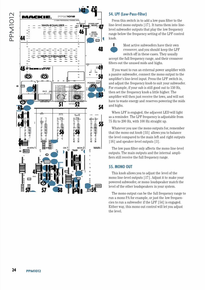
8/22/2019 Mackie PPM1012 12 Channel Powered Mixer Manual
http://slidepdf.com/reader/full/mackie-ppm1012-12-channel-powered-mixer-manual 24/36
)+ GGD('()
G G D ( ' ( ) 54. LPF (Low-Pass-Filter)
Press this switch in to add a low-pass filter to the
line-level mono outputs [17]. It turns them into line-
level subwoofer outputs that play the low frequency
range below the frequency setting of the LPF control
knob.
Most active subwoofers have their own
crossover, and you should keep the LPFswitch off in these cases. They usually
accept the full frequency range, and their crossover
filters out the unused mids and highs.
If you want to run an external power amplifier with
a passive subwoofer, connect the mono output to the
amplifier's line-level input. Press the LPF switch in,
and adjust the frequency knob to suit your subwoofer.
For example, if your sub is still good out to 150 Hz,
then set the frequency knob a little higher. The
amplifier will then just receive the lows, and will not
have to waste energy and reserves powering the midsand highs.
When LPF is engaged, the adjacent LED will light
as a reminder. The LPF frequency is adjustable from
75 Hz to 200 Hz, with 100 Hz straight up.
Whatever you use the mono outputs for, remember
that the mono out knob [55] allows you to balance
the level compared to the main left and right outputs
[16] and speaker-level outputs [3].
The low pass filter only affects the mono line-level
outputs. The main outputs and the internal ampli-fiers still receive the full frequency range.
55. MONO OUT
This knob allows you to adjust the level of the
mono line-level outputs [17]. Adjust it to make your
powered subwoofer, or mono loudspeaker match the
level of the other loudspeakers in your system.
The mono output can be the full frequency range to
run a mono PA for example, or just the low frequen-
cies to run a subwoofer if the LPF [54] is engaged.Either way, this mono out control will let you adjust
the level.
I
FX 1 FX 2
TAPDELAY
INT FX MUTE
TAPDELAY
INT FX MUTE
TAP TO EDIT
01 PLATE REVERB
02 VOCAL PLATE03 WARM ROOM04 BRIGHT ROOM
13 CHORUS
14 CHORUS + REVERB15 DOUBLER16 TAPE SLAP
05 WARM LOUNGE06 SMALL STAGE07 WARM THEATER08 BRIGHT STAGE09 WARM HALL
10 CONCERT HALL11 CATHEDRAL
12 GATED REVERB
17 DLY 1 BRIGHT (350ms)18 DLY 1 WARM (300ms)19 DLY 2 BRIGHT (250ms)20 DLY 2 WARM (200ms)21 DLY 3 BRIGHT (175ms)
22 DLY 3 WARM (150ms)23 CHORUS + DLY (300ms)
24 REVERB + DLY (200ms)
15
15
10
10
5
5
0
15
15
10
10
5
5
0
16K 8K 4K 2K 1K 50025012563
OL
4
6
3
10
15
7
10
20
30
0
2
U
+20 OO
TAPE IN
BREAK
MUTESCH 1-12
U
+15 OO
U
+15 OO
TO MON 1 TO MON 2
FX 1 FX 1MONO OUT
LPF
OOMAX
75Hz
100 180
120
200Hz
0dB = 0dBu
LEVEL
SET
RUDESOLO
MAINMON 2
EQ ASSIGN
MAINMETERS
RL
PHANTOMPOWER
MAIN EQUALIZER
MON 1 EQUALIZER
15
15
10
10
5
5
0
15
15
10
10
5
5
0
16K 8K 4K 2K 1K 50025012563
SIG/OLSIG/OL
U
+15 OO
SEND MASTER
U
+15 OO
SEND MASTER
SOLO
dB
30
20
10
OO
40
50
5
5
U
60
SOLO
dB
30
20
10
OO
40
50
5
5
U
60
SOLO
dB
30
20
10
OO
40
50
5
5
U
60
SOLO
dB
30
20
10
OO
40
50
5
5
U
60
dB
30
20
10
OO
40
50
5
5
U
60
FX RTN 1 FX RTN 2 MON1 MON 2 MAIN
2 X 800W PROFESSIONAL POWERED MIXER
10 10 10 10 10
(L) (R)
MON 1
MON 2
MAINS
MON 1
STEREOMAIN
A B
POWER AMPLIMITER
A B
POWER AMPMODE
53
54
55
52 51
56
60
62
63
64
61
59 57 58 57 58
56
42 43
44
45
4647
49
50
48
38
41
8/22/2019 Mackie PPM1012 12 Channel Powered Mixer Manual
http://slidepdf.com/reader/full/mackie-ppm1012-12-channel-powered-mixer-manual 25/36
),Fne\iËjDXelXc
F ne \i Ë j D Xe l X c
56. FX 1 TO MON 1 and FX 1 TO MON 2
These knobs let you adjust the level of the internal
effects processor 1 output (summed mono) being added
to the monitor 1 mix and the monitor 2 mix.
Adjust the level carefully, compared to the other chan-
nels playing in the monitor 1 and 2 stage monitors.
At the fully-down position, no FX 1 effects are added,
the center U mark is unity gain, and there is 15 dB of effects gain fully up.
57. FX RTN 1 FADER and FX RTN 2 FADER
These stereo faders let you adjust how much of the in-
ternal effects from processor 1 and processor 2 is added
to the main mix. (The output from the internal effects
processors is in stereo, and is added to the main left and
right mix.) The faders also allow you to adjust the level
of signals coming into the FX 1 and FX 2 return inputs
[12] from external processors (for example), being
added to the main mix.
Adjust each fader and listen to the effects compared
to the other channels playing in the main mix.
At the fully-down position, no effects are added, the
U mark is unity gain, and there is 10 dB of effects gain
fully up.
The solo buttons [41] next to these faders
allow you to listen to the output of the effects
processor in your headphones. These faders
have no effect on the solo level, so protect your hearingby making sure the phones knob [19] is turned down
before you press solo.
The mute buttons [38] above these faders allow you
to quickly turn off the effects being added to the main
mix and monitors. (You can still solo them.)
58. MONITOR 1 FADER and MONITOR 2 FADER
These faders control the level of the monitor 1 mix
and monitor 2 signals sent to the mon 1 and mon 2
line-level outputs [10], and the monitor speaker-level
outputs [3] if the internal power amplifiers are playingmonitor 1 or 2.
These give you ultimate control over your stage moni-
tors. Adjust them carefully to prevent overloading, and
check to see that your band are happy with the levels.
The controls do not affect the main mix level.
The monitor signals are off with the levels fully down,
the “U” marking is unity gain, and fully up provides 10
dB of additional gain.
The solo buttons [41] next to these faders al-
low you to listen to the monitor output in your
headphones. These faders have no effect on
the solo level, so to protect your hearing, make sure the
phones knob [19] is turned down before you press solo.
59. MAIN FADER
This stereo fader controls the levels of the main mix
signals sent to the main line-level outputs [16, 17], and
the main speaker-level outputs [3] if the internal power
amplifiers are playing the main mix. The fader comes
after the EQ [44] and before the meters [48].
This gives you the ultimate feeling of power and con-
trol over the sound levels sent to your audience. Adjustit carefully, with your good eye on the meters to check
against overloading, and your good ear to the levels to
make sure your audience is happy.
The fader does not affect the monitor 1 or monitor 2
outputs [10], or the internal power amp if it is playing a
monitor.
The main mix signals are off with the fader fully down,
the “U” marking is unity gain, and fully up provides 10
dB of additional gain. This additional gain will typically
never be needed, but once again, it’s nice to know it’s
there. The fader is stereo, as it affects both the left and
right of the main mix equally. This is the ideal control to
slowly bring down at the end of a song (or quickly in the
middle of a song if the need ever arises).
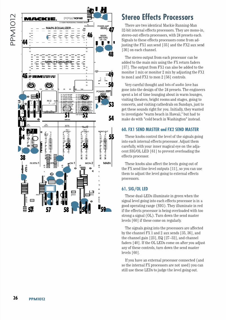
8/22/2019 Mackie PPM1012 12 Channel Powered Mixer Manual
http://slidepdf.com/reader/full/mackie-ppm1012-12-channel-powered-mixer-manual 26/36
)- GGD('()
G G D ( ' ( ) Stereo Effects Processors
There are two identical Mackie Running-Man
32-bit internal effects processors. They are mono-in,
stereo-out effects processors, with 24 presets each.
Signals to these effects processors come from ad-
justing the FX1 aux send [35] and the FX2 aux send
[36] on each channel.
The stereo output from each processor can beadded to the main mix using the FX return faders
[57]. The output from FX1 can also be added to the
monitor 1 mix or monitor 2 mix by adjusting the FX1
to mon1 and FX1 to mon 2 [56] controls.
Very careful thought and lots of audio love has
gone into the design of the 24 presets. The engineers
spent a lot of time lounging about in warm lounges,
visiting theaters, bright rooms and stages, going to
concerts, and visiting cathedrals on Sundays, just to
get these sounds right for you. Initially, they wanted
to investigate "warm beach in Hawaii," but had to
make do with "cold beach in Washington" instead.
60. FX1 SEND MASTER and FX2 SEND MASTER
These knobs control the level of the signals going
into each internal effects processor. Adjust them
carefully, with your inner magical eye on the adja-
cent SIG/OL LED [61] to prevent overloading the
effects processor.
These knobs also affect the levels going out of
the FX send line-level outputs [11], so you can usethem to adjust the level going to external effects
processors.
61. SIG/OL LED
These dual-LEDs illuminate in green when the
signal level going into each effects processor is in a
good operating range (SIG). They illuminate in red
if the effects processor is being overloaded with too
strong a signal (OL). Turn down the send master
levels [60] if these come on regularly.
The signals going into the processors are affected
by the channel FX 1 and 2 aux sends [35, 36], and
the channel gain [23], EQ [27–32], and channel
faders [40]. If the OL LEDs come on after you adjust
any of these controls, turn down the send master
levels [60].
If you have an external processor connected (and
so the internal FX processors are not used) you can
still use these LEDs to judge the level going out.
I
FX 1 FX 2
TAPDELAY
INT FX MUTE
TAPDELAY
INT FX MUTE
TAP TO EDIT
01 PLATE REVERB
02 VOCAL PLATE03 WARM ROOM04 BRIGHT ROOM
13 CHORUS
14 CHORUS + REVERB15 DOUBLER16 TAPE SLAP
05 WARM LOUNGE06 SMALL STAGE07 WARM THEATER08 BRIGHT STAGE09 WARM HALL
10 CONCERT HALL11 CATHEDRAL
12 GATED REVERB
17 DLY 1 BRIGHT (350ms)18 DLY 1 WARM (300ms)19 DLY 2 BRIGHT (250ms)20 DLY 2 WARM (200ms)21 DLY 3 BRIGHT (175ms)
22 DLY 3 WARM (150ms)23 CHORUS + DLY (300ms)
24 REVERB + DLY (200ms)
15
15
10
10
5
5
0
15
15
10
10
5
5
0
16K 8K 4K 2K 1K 50025012563
OL
4
6
3
10
15
7
10
20
30
0
2
U
+20 OO
TAPE IN
BREAK
MUTESCH 1-12
U
+15 OO
U
+15 OO
TO MON 1 TO MON 2
FX 1 FX 1MONO OUT
LPF
OOMAX
75Hz
100 180
120
200Hz
0dB = 0dBu
LEVEL
SET
RUDESOLO
MAINMON 2
EQ ASSIGN
MAINMETERS
RL
PHANTOMPOWER
MAIN EQUALIZER
MON 1 EQUALIZER
15
15
10
10
5
5
0
15
15
10
10
5
5
0
16K 8K 4K 2K 1K 50025012563
SIG/OLSIG/OL
U
+15 OO
SEND MASTER
U
+15 OO
SEND MASTER
SOLO
dB
30
20
10
OO
40
50
5
5
U
60
SOLO
dB
30
20
10
OO
40
50
5
5
U
60
SOLO
dB
30
20
10
OO
40
50
5
5
U
60
SOLO
dB
30
20
10
OO
40
50
5
5
U
60
dB
30
20
10
OO
40
50
5
5
U
60
FX RTN 1 FX RTN 2 MON1 MON 2 MAIN
2 X 800W PROFESSIONAL POWERED MIXER
10 10 10 10 10
(L) (R)
MON 1
MON 2
MAINS
MON 1
STEREOMAIN
A B
POWER AMPLIMITER
A B
POWER AMPMODE
53
54
55
52 51
56
60
62
63
64
61
59 57 58 57 58
56
42 43
44
45
4647
49
50
48
38
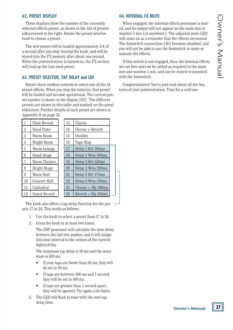
8/22/2019 Mackie PPM1012 12 Channel Powered Mixer Manual
http://slidepdf.com/reader/full/mackie-ppm1012-12-channel-powered-mixer-manual 27/36
).Fne\iËjDXelXc
F ne \i Ë j D Xe l X c
62. PRESET DISPLAY
These displays show the number of the currently
selected effects preset, as shown in the list of presets
silkscreened to the right. Rotate the preset selector
knob to choose a preset.
The new preset will be loaded approximately 1/4 of
a second after you stop turning the knob, and will be
stored into the FX memory after about one second.When the powered mixer is turned on, the FX section
will load up the last-used preset.
63. PRESET SELECTOR, TAP DELAY and LED
Rotate these endless controls to select one of the 24
preset effects. When you stop the rotation, that preset
will be loaded and become operational. The current pre-
set number is shown in the display [62]. The different
presets are shown in this table and marked on the panel
silkscreen. Further details of each preset are shown in
Appendix D on page 34.
The knob also offers a tap delay function for the pre-
sets 17 to 24. This works as follows:
1. Use the knob to select a preset from 17 to 24.
2. Press the knob in at least two times.
The DSP processor will calculate the time delay between the last two pushes, and it will assign
this time interval to the echoes of the current
digital delay.
The minimum tap delay is 50 ms and the maxi-
mum is 500 ms.
• If your taps are faster than 50 ms, they will
be set to 50 ms.
• If taps are between 500 ms and 1 second,
they will be set to 500 ms.
• If taps are greater than 1 second apart,
they will be ignored. Try again a bit faster.
3. The LED will flash in time with the new tap
delay time.
64. INTERNAL FX MUTE
When engaged, the internal effects processor is mut-
ed, and its output will not appear on the main mix or
monitor 1 mix (or anywhere). The adjacent mute LED
will come on as a reminder that the effects are muted.
The footswitch connection [20] becomes disabled, and
you will not be able to use the footswitch to mute or
unmute the effects.
If this switch is not engaged, then the internal effects
are set free and can be added as required to the main
mix and monitor 1 mix, and can be muted or unmuted
with the footswitch.
Congratulations! You’ve just read about all the fea-
tures of your powered mixer. Time for a cold one.
1 Plate Reverb 13 Chorus
2 Vocal Plate 14 Chorus + Reverb
3 Warm Room 15 Doubler
4 Bright Room 16 Tape Slap
5 Warm Lounge 17 Delay 1 Brt 350ms
6 Small Stage 18 Delay 1 Wrm 300ms
7 Warm Theater 19 Delay 2 Brt 250ms
8 Bright Stage 20 Delay 2 Wrm 200ms
9 Warm Hall 21 Delay 3 Brt 175ms
10 Concert Hall 22 Delay 3 Wrm 150ms
11 Cathedral 23 Chorus + Dly 300ms
12 Gated Reverb 24 Reverb + Dly 200ms
8/22/2019 Mackie PPM1012 12 Channel Powered Mixer Manual
http://slidepdf.com/reader/full/mackie-ppm1012-12-channel-powered-mixer-manual 28/36
)/ GGD('()
G G D ( ' ( ) Appendix A: Service Information
If you think your powered mixer has a problem, please
check out the following troubleshooting tips and do your
best to confirm the problem. Visit the Support section of
our website (www.mackie.com) where you will find lots
of useful information such as FAQs, and documentation.
You may find the answer to the problem without having
to send your mixer away.
Troubleshooting
9X[:_Xee\c
• Is the channel EQ set up nicely?
• Is the channel gain set correctly?
• Is the channel fader up enough?
• Is the channel OL led on?
• Is the channel pan set in the middle?
• Is there too much compression on channels
1-6?
• Are the hi-z instrument switches set OK for
guitars connected to channels 7 and 8?
• Try unplugging any insert devices from the
insert jacks on channels 1 to 8.
• Try the same source signal in another channel,
set up exactly like the suspect channel.
• Is phantom power required for your micro-
phones?
9X[Flkglk
• Is the main fader turned up?
• Check the power amp mode switch is set cor-
rectly.
• Are the graphic EQs set to reasonable levels?
• Is the FX level going to the main mix, too high?
• If it’s one of the main speaker-level outputs,try unplugging its companion. For example, if
it’s the 1/4" left main output, unplug the left
Speakon output. If the problem goes away, it’s
not the powered mixer.
• If a left speaker is presumed dead, connect it
to the right output instead. If the problem stays
with the same speaker, check the speaker wir-
ing, or any speaker fuses.
• Unplug anything from the main line-level out-
puts, main inserts, or other line-level outputs,
such as mono out, mon 1 send, mon 2 send, FX1
and FX2 send, just in case one of your external
pieces has a problem.
• If the power amp limiter lights come on often, you may be overdriving the amplifiers. Check
the loudspeaker average load impedance is not
less than 4 ohms. Check the speaker wiring.
Ef`j\
• Turn the channel gains down, one by one. If the
sound disappears, it’s either that channel or
whatever is plugged into it, so unplug whatever
that is. If the noise disappears, it’s from your
whatever.
Gfn\i
• The power LED should come on if the powered
mixer is connected to a suitable live AC mains
outlet, and the power switch is on. Check the
power cord is securely plugged in.
C\m`kXk`fe
• The heavy combined weight of all the loud-
speaker electrons is balanced by the fans and warm air that make things lighter. During
louder moments when all the electrons are sent
rushing out to your loudspeakers, you may find
that the powered mixer will rise in the air and
hover up and down in sync with the music. This
is perfectly normal.
RepairFor warranty service, refer to the warranty informa-
tion on page 35.
Non-warranty service for Mackie products is avail-
able at a factory-authorized service center. To locate
your nearest service center, visit www.mackie.com, click
“Support” and select “Locate a Service Center.” Service
for Mackie products living outside the United States can
be obtained through local dealers or distributors.
If you do not have access to our website, you can call
our Tech Support department at 1-800-898-3211, Mon-
day-Friday, normal business hours, PST, to explain the
problem. Tech Support will tell you where the nearest
factory-authorized service center is located in your area.
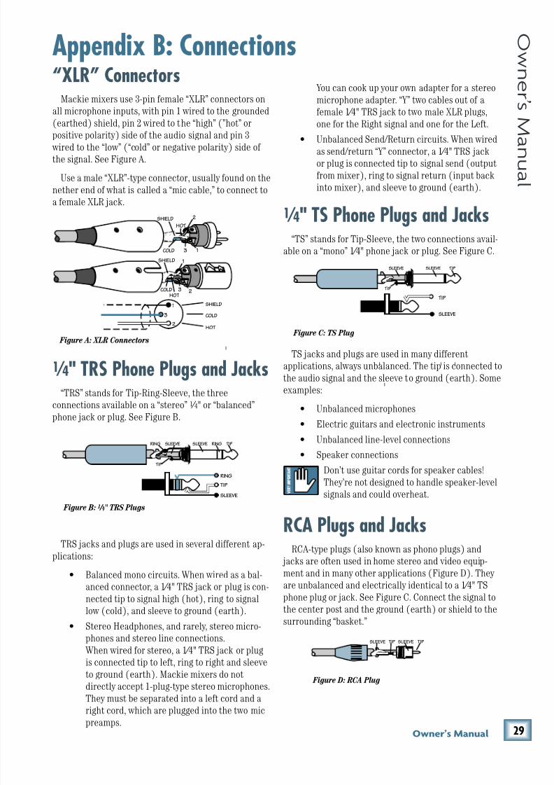
8/22/2019 Mackie PPM1012 12 Channel Powered Mixer Manual
http://slidepdf.com/reader/full/mackie-ppm1012-12-channel-powered-mixer-manual 29/36
)0Fne\iËjDXelXc
F ne \i Ë j D Xe l X c
“XLR” ConnectorsMackie mixers use 3-pin female “XLR” connectors on
all microphone inputs, with pin 1 wired to the grounded
(earthed) shield, pin 2 wired to the “high” (”hot” or
positive polarity) side of the audio signal and pin 3 wired to the “low” (“cold” or negative polarity) side of
the signal. See Figure A.
Use a male “XLR”-type connector, usually found on the
nether end of what is called a “mic cable,” to connect to
a female XLR jack.
1 ⁄ 4" TRS Phone Plugs and Jacks“TRS” stands for Tip-Ring-Sleeve, the three
connections available on a “stereo” 1 ⁄ 4" or “balanced”
phone jack or plug. See Figure B.
TRS jacks and plugs are used in several different ap-
plications:
• Balanced mono circuits. When wired as a bal-
anced connector, a 1⁄4" TRS jack or plug is con-
nected tip to signal high (hot), ring to signal
low (cold), and sleeve to ground (earth).
• Stereo Headphones, and rarely, stereo micro-
phones and stereo line connections.
When wired for stereo, a 1⁄4" TRS jack or plug
is connected tip to left, ring to right and sleeve
to ground (earth). Mackie mixers do not
directly accept 1-plug-type stereo microphones.They must be separated into a left cord and a
right cord, which are plugged into the two mic
preamps.
Appendix B: ConnectionsYou can cook up your own adapter for a stereo
microphone adapter. “Y” two cables out of a
female 1⁄4" TRS jack to two male XLR plugs,
one for the Right signal and one for the Left.
• Unbalanced Send/Return circuits. When wiredas send/return “Y” connector, a 1⁄4" TRS jack
or plug is connected tip to signal send (output
from mixer), ring to signal return (input back
into mixer), and sleeve to ground (earth).
1 ⁄ 4" TS Phone Plugs and Jacks“TS” stands for Tip-Sleeve, the two connections avail-
able on a “mono” 1⁄4" phone jack or plug. See Figure C.
TS jacks and plugs are used in many different
applications, always unbalanced. The tip is connected to
the audio signal and the sleeve to ground (earth). Some
examples:
• Unbalanced microphones• Electric guitars and electronic instruments
• Unbalanced line-level connections
• Speaker connections
Don’t use guitar cords for speaker cables!
They’re not designed to handle speaker-level
signals and could overheat.
RCA Plugs and JacksRCA-type plugs (also known as phono plugs) and
jacks are often used in home stereo and video equip-
ment and in many other applications (Figure D). They
are unbalanced and electrically identical to a 1⁄4" TS
phone plug or jack. See Figure C. Connect the signal to
the center post and the ground (earth) or shield to the
surrounding “basket.”
SLEEVE
TIP
TIPSLEEVE
TIP
SLEEVE
II
I
I
Figure C: TS Plug
2
2
3 1
1
SHIELD
COLD
HOT
SHIELD
COLD
HOT
3
SHIELD
COLD
HOT
3
2
1
Figure A: XLR ConnectorsI
I
SLEEVE
TIPSLEEVE
TIP
RING
RING
TIP
SLEEVERING
Figure B: 1 ⁄ 4" TRS Plugs
TIPSLEEVETIPSLEEVE
Figure D: RCA Plug
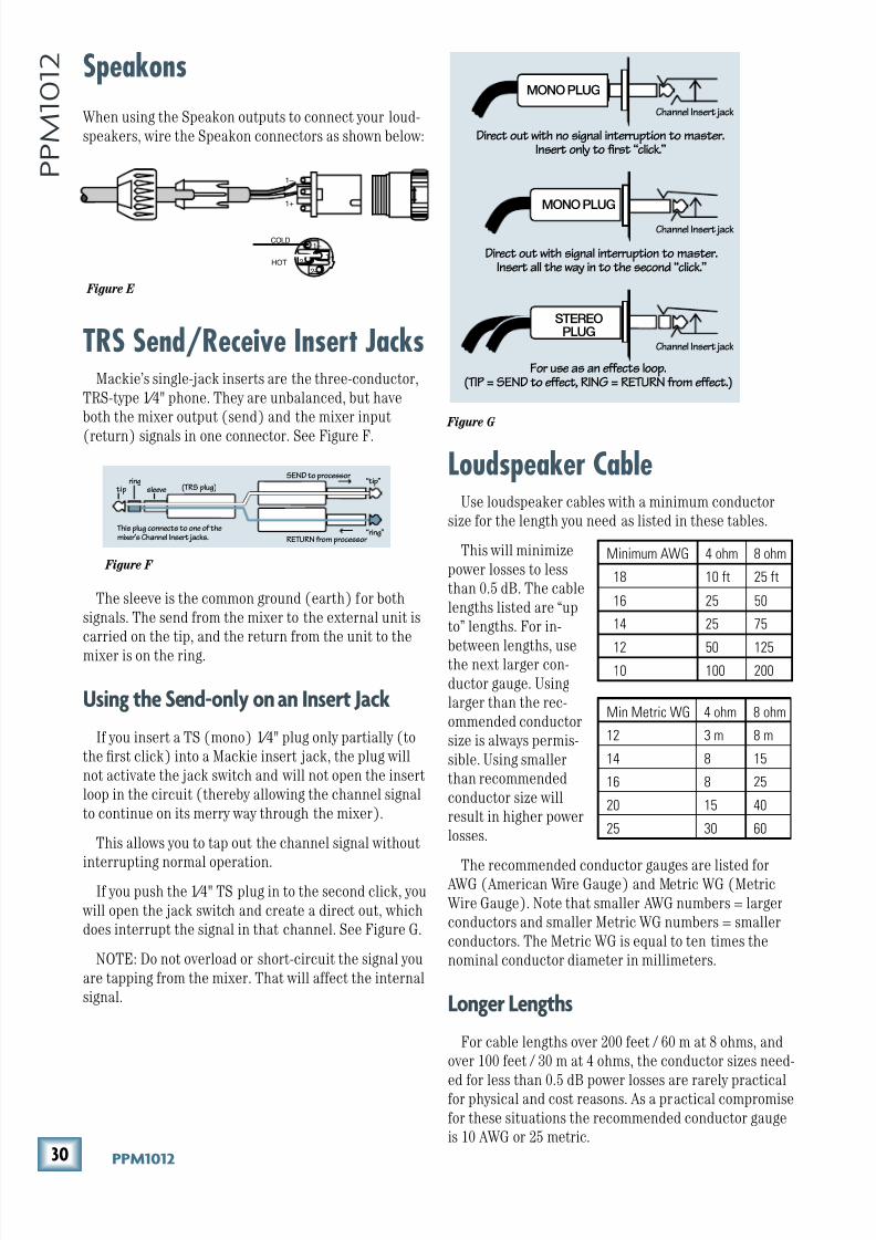
8/22/2019 Mackie PPM1012 12 Channel Powered Mixer Manual
http://slidepdf.com/reader/full/mackie-ppm1012-12-channel-powered-mixer-manual 30/36
*' GGD('()
G G D ( ' ( )
Loudspeaker CableUse loudspeaker cables with a minimum conductor
size for the length you need as listed in these tables.
This will minimize
power losses to less
than 0.5 dB. The cable
lengths listed are “up
to” lengths. For in-
between lengths, usethe next larger con-
ductor gauge. Using
larger than the rec-
ommended conductor
size is always permis-
sible. Using smaller
than recommended
conductor size will
result in higher power
losses.
The recommended conductor gauges are listed for AWG (American Wire Gauge) and Metric WG (Metric
Wire Gauge). Note that smaller AWG numbers = larger
conductors and smaller Metric WG numbers = smaller
conductors. The Metric WG is equal to ten times the
nominal conductor diameter in millimeters.
Cfe^\iC\e^k_j
For cable lengths over 200 feet / 60 m at 8 ohms, and
over 100 feet / 30 m at 4 ohms, the conductor sizes need-
ed for less than 0.5 dB power losses are rarely practicalfor physical and cost reasons. As a practical compromise
for these situations the recommended conductor gauge
is 10 AWG or 25 metric.
Speakons
When using the Speakon outputs to connect your loud-
speakers, wire the Speakon connectors as shown below:
TRS Send/Receive Insert JacksMackie’s single-jack inserts are the three-conductor,
TRS-type 1⁄4" phone. They are unbalanced, but have
both the mixer output (send) and the mixer input
(return) signals in one connector. See Figure F.
The sleeve is the common ground (earth) for both
signals. The send from the mixer to the external unit is
carried on the tip, and the return from the unit to the
mixer is on the ring.
Lj`e^k_\J\e[$fecpfeXe@ej\ikAXZb
If you insert a TS (mono) 1⁄4" plug only partially (to
the first click) into a Mackie insert jack, the plug will
not activate the jack switch and will not open the insert
loop in the circuit (thereby allowing the channel signal
to continue on its merry way through the mixer).
This allows you to tap out the channel signal without
interrupting normal operation.If you push the 1⁄4" TS plug in to the second click, you
will open the jack switch and create a direct out, which
does interrupt the signal in that channel. See Figure G.
NOTE: Do not overload or short-circuit the signal you
are tapping from the mixer. That will affect the internal
signal.
“tip”
This plug connects to one of themixer’s Channel Insert jacks.
“ring”
tipring
sleeve
SEND to processor
RETURN from processor
(TRS plug)
Figure F
Direct out with no signal interruption to master.Insert only to first “click.”
Channel Insert jack
Channel Insert jack
Channel Insert jack
Direct out with signal interruption to master.Insert all the way in to the second “click.”
For use as an effects loop.(TIP = SEND to effect, RING = RETURN from effect.)
MONO PLUG
MONO PLUG
STEREO
PLUG
Figure G
Figure E
COLD
HOT1+
1+
1–
1–
2–
2+
Minimum AWG 4 ohm 8 ohm
18 10 ft 25 ft
16 25 50
14 25 75
12 50 12510 100 200
Min Metric WG 4 ohm 8 ohm
12 3 m 8 m
14 8 15
16 8 25
20 15 40
25 30 60
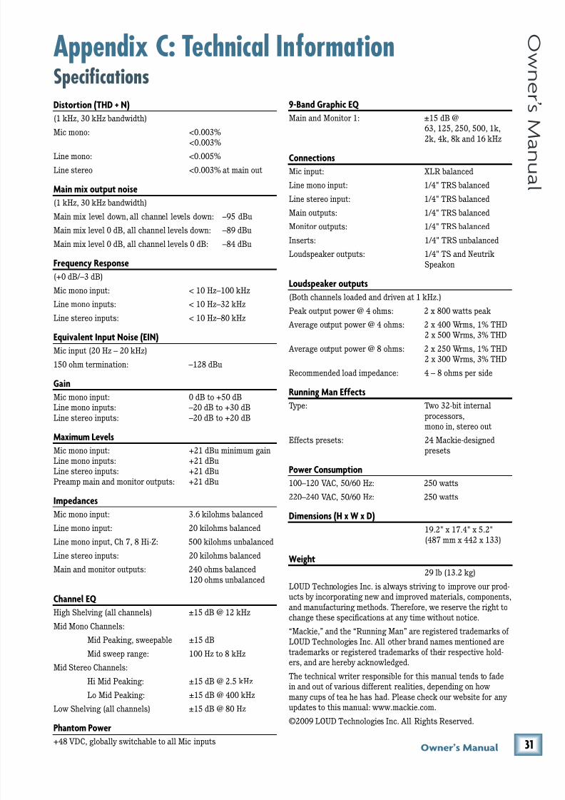
8/22/2019 Mackie PPM1012 12 Channel Powered Mixer Manual
http://slidepdf.com/reader/full/mackie-ppm1012-12-channel-powered-mixer-manual 31/36
*(Fne\iËjDXelXc
F ne \i Ë j D Xe l X c
Appendix C: Technical InformationSpecifications;`jkfik`feK?;"E
(1 kHz, 30 kHz bandwidth)
Mic mono: <0.003%
<0.003%
Line mono: <0.005%
Line stereo <0.003% at main out
DX`ed`oflkglkef`j\
(1 kHz, 30 kHz bandwidth)
Main mix level down, all channel levels down: –95 dBu
Main mix level 0 dB, all channel levels down: –89 dBu
Main mix level 0 dB, all channel levels 0 dB: –84 dBu
=i\hl\eZpI\jgfej\
(+0 dB/–3 dB)Mic mono input: < 10 Hz–100 kHz
Line mono inputs: < 10 Hz–32 kHz
Line stereo inputs: < 10 Hz–80 kHz
<hl`mXc\ek@eglkEf`j\<@E
Mic input (20 Hz – 20 kHz)
150 ohm termination: –128 dBu
>X`e
Mic mono input: 0 dB to +50 dB
Line mono inputs: –20 dB to +30 dB
Line stereo inputs: –20 dB to +20 dB
DXo`dldC\m\cj
Mic mono input: +21 dBu minimum gain
Line mono inputs: +21 dBu
Line stereo inputs: +21 dBu
Preamp main and monitor outputs: +21 dBu
@dg\[XeZ\j
Mic mono input: 3.6 kilohms balanced
Line mono input: 20 kilohms balanced
Line mono input, Ch 7, 8 Hi-Z: 500 kilohms unbalanced
Line stereo inputs: 20 kilohms balanced
Main and monitor outputs: 240 ohms balanced
120 ohms unbalanced
:_Xee\c<H
High Shelving (all channels) ±15 dB @ 12 kHz
Mid Mono Channels:
Mid Peaking, sweepable ±15 dB
Mid sweep range: 100 Hz to 8 kHz
Mid Stereo Channels:
Hi Mid Peaking: ±15 dB @ 2.5 kHz
Lo Mid Peaking: ±15 dB @ 400 kHz
Low Shelving (all channels) ±15 dB @ 80 Hz
G_XekfdGfn\i
+48 VDC, globally switchable to all Mic inputs
0$9Xe[>iXg_`Z<H
Main and Monitor 1: ±15 dB @
63, 125, 250, 500, 1k,
2k, 4k, 8k and 16 kHz
:fee\Zk`fej
Mic input: XLR balanced
Line mono input: 1/4" TRS balanced
Line stereo input: 1/4" TRS balanced
Main outputs: 1/4" TRS balanced
Monitor outputs: 1/4" TRS balanced
Inserts: 1/4" TRS unbalanced
Loudspeaker outputs: 1/4" TS and Neutrik
Speakon
Cfl[jg\Xb\iflkglkj
(Both channels loaded and driven at 1 kHz.)
Peak output power @ 4 ohms: 2 x 800 watts peak
Average output power @ 4 ohms: 2 x 400 Wrms, 1% THD
2 x 500 Wrms, 3% THD
Average output power @ 8 ohms: 2 x 250 Wrms, 1% THD
2 x 300 Wrms, 3% THD
Recommended load impedance: 4 – 8 ohms per side
Ilee`e^DXe<]]\Zkj
Type: Two 32-bit internal
processors,mono in, stereo out
Effects presets: 24 Mackie-designed
presets
Gfn\i:fejldgk`fe
100–120 VAC, 50/60 Hz: 250 watts
220–240 VAC, 50/60 Hz: 250 watts
;`d\ej`fej?oNo;
19.2" x 17.4" x 5.2"
(487 mm x 442 x 133)
N\`^_k29 lb (13.2 kg)
LOUD Technologies Inc. is always striving to improve our prod-
ucts by incorporating new and improved materials, components,
and manufacturing methods. Therefore, we reserve the right to
change these specifications at any time without notice.
“Mackie,” and the “Running Man” are registered trademarks of
LOUD Technologies Inc. All other brand names mentioned are
trademarks or registered trademarks of their respective hold-
ers, and are hereby acknowledged.
The technical writer responsible for this manual tends to fade
in and out of various different realities, depending on how
many cups of tea he has had. Please check our website for any updates to this manual: www.mackie.com.
©2009 LOUD Technologies Inc. All Rights Reserved.
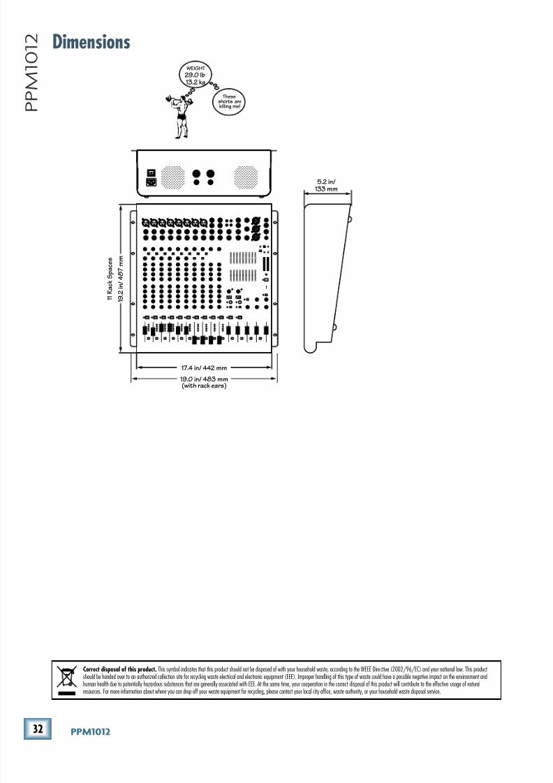
8/22/2019 Mackie PPM1012 12 Channel Powered Mixer Manual
http://slidepdf.com/reader/full/mackie-ppm1012-12-channel-powered-mixer-manual 32/36
*) GGD('()
G G D ( ' ( ) Dimensions
1 9 . 2
i n / 4 8
7 m m
1 1 R a c k S p
a c e s
17.4 in/ 442 mm
5.2 in/133 mm
WEIGHT
29.0 lb13.2 kg
Theseshorts arekilling me!
19.0 in/ 483 mm(with rack ears)
Correct disposal of this product. This symbol indicates that this product should not be disposed of with your household waste, according to the WEEE Dire ctive (2002/96/EC) and your national law. This product should be handed over to an authorized collection site for recycling waste electrical and electronic equipment (EEE). Improper handling of this type of waste could have a possible negative impact on the environment and
human health due to potentially hazardous substances that are generally associated with EEE. At the same time, your cooperation in the correct disposal of this product will contribute to the effective usage of naturalresources. For more information about where you can drop off your waste equipment for recycling, please contact your local city office, waste authority, or your household waste disposal service.
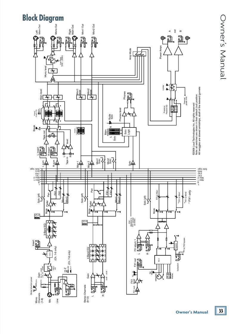
8/22/2019 Mackie PPM1012 12 Channel Powered Mixer Manual
http://slidepdf.com/reader/full/mackie-ppm1012-12-channel-powered-mixer-manual 33/36
**Fne\iËjDXelXc
F ne \i Ë j D Xe l X c
Block Diagram
4 8 V
L
R
M a i n l e v e l
S t e r e o C h
a n n e l s
( 9 - 1 2 ) L R
I n s e r t
F a d e r
F a d e r M
o n 1
L e f t
M a i n O u t
R i g h t
M a i n O u t
o u t
A B
L s u m
3 - B a n d E Q
4 - B a n d E Q
M o n 1
L O
M I D
8 0
1 0 0 ~ 8 K
1 2 K
H I
F X 1
G l o
b a l p h a n t o m p o w e r
p h t m
F X 1
L o w P a s
s
M o n o O u t
F
X 1 s u m
M o n 1
S o l o
M o n 2 F X 1
M o n 1
O L
S i g
s e l e c t / t a p t a
p
d e l a y
F X 1
d i s p l a y
b y p a s s
F X 1 t o M a i n
f o o t s w i t c h
F X 1 t o M o n 1
L O
M I D
M I D
8 0
4 0 0
2 . 5 K
1 2 K
H I
L O
M I D
M I D
8 0
4 0 0
2 . 5 K
1 2 K
H I
B r e a k
T a p e o u t
M o n 1 O u t
P r e c i s i o n
P a s s i v e E Q
A m p M o d e
L i m i t e r
P
o w e r A m p s
F X 1 o u t
F X 1
l e v e l
L R
C o m p
F X 2
S o l o l o g i c
L R
S o l o
M o n 2 F X 1
M o n 1
F X 2
S o l o l o g i c R s u m
P a n
S o l o ( p f l )
F X 2
M o n 2
M u t e
P a n
F X 2
M o n 2
L R
+ - + -
S o l o ( p f l )
M u t e
L I n s e r t
R I n s e r t
T a p e i n
l e v e l
M o n 2
M o n 2 O u t
M o n 2
M a i n
9 - b a n d
G r a p h i c E Q
9 - b a n d
G
r a p h i c E Q
M o n 2
l e v e l
M o n 1
l e v e l
F X 1 t o M o n 2
M u t e
S o l o ( p f l )
F X 2
i d e n t i c a l t o
F X 1 e x c e p t
a s n o t e d
F X r e t u r n 1
L R
7 5 H z ~ 2 0 0
H z
S o l o
P h o n e s
P h o n
e s l e v e l
S o l o
L o g i c
M a i n
m e t e r s
L
R
S o l o
M o n 1
S o l o
M o n 2
S o l o
- 2 0 d B ~ + 2 0 d B
G a i n
R u d e
S o
l o
M o n o l e v e l
P K 0
- 2 0
+ 1 0
P K 0
- 2 0
+ 1 0
* * * F X 1 o n l y
t o F X 2 b y p a s s
T h e r m a l
p o w e r l i m i t
+ - + -
M o n o
C h a n n e l s
( 1 - 8 )
M i c
L i n e
G a i n
M i c : 0 ~ + 5 0 d B
L i n e : - 2 0 ~ + 3 0 d B
p h t m
+ -
1 0 0 H z
H P F
H I - Z
L I N E
H i - Z
( C h . 7 - 8 o n l y )
( C h . 1 - 6 o n l y )
© 2 0 0 8 L o u d T e c h n o l o g i e s I n c . A l l r i g
h t s r e s e r v e d
N o t e : a l l s w i t c h e s a r e s h o w n i n t h e i r
d e f a u l t ( o u t ) p o s i t i o n
A l l t w o g g l e s a r e s t o w e d a m i d s h i p s , a b a f t o f t h e l e e w a r d g u n n e l s
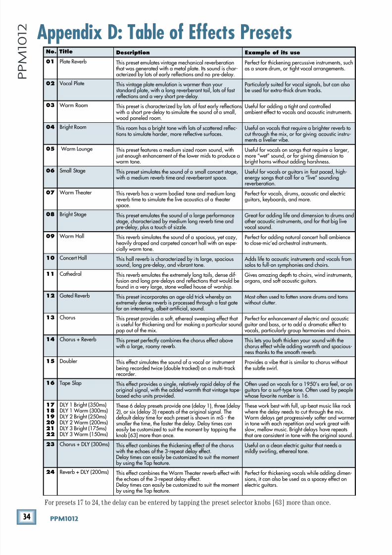
8/22/2019 Mackie PPM1012 12 Channel Powered Mixer Manual
http://slidepdf.com/reader/full/mackie-ppm1012-12-channel-powered-mixer-manual 34/36
*+ GGD('()
G G D ( ' ( ) Appendix D: Table of Effects Presets
No. Title Description Example of its use
01 Plate Reverb This preset emulates vintage mechanical reverberationthat was generated with a metal plate. Its sound is char-acterized by lots of early reflections and no pre-delay.
Perfect for thickening percussive instruments, suchas a snare drum, or tight vocal arrangements.
02 Vocal Plate This vintage plate emulation is warmer than your standard plate, with a long reverberant tail, lots of fast
reflections and a very short pre-delay.
Particularly suited for vocal signals, but can alsobe used for extra-thick drum tracks.
03 Warm Room This preset is characterized by lots of fast early reflections with a short pre-delay to simulate the sound of a small, wood paneled room.
Useful for adding a tight and controlledambient effect to vocals and acoustic instruments.
04 Bright Room This room has a bright tone with lots of scattered reflec-tions to simulate harder, more reflective surfaces.
Useful on vocals that require a brighter reverb tocut through the mix, or for giving acoustic instru-ments a livelier vibe.
05 Warm Lounge This preset features a medium sized room sound, withjust enough enhancement of the lower mids to produce a
warm tone.
Useful for vocals on songs that require a larger,more “wet” sound, or for giving dimension tobright horns without adding harshness.
06 Small Stage This preset simulates the sound of a small concert stage, with a medium reverb time and reverberant space.
Useful for vocals or guitars in fast paced, high-energy songs that call for a “live” soundingreverberation.
07 Warm Theater This reverb has a warm bodied tone and medium longreverb time to simulate the live acoustics of a theater space.
Perfect for vocals, drums, acoustic and electricguitars, keyboards, and more.
08 Bright Stage This preset emulates the sound of a large performancestage, characterized by medium long reverb time andpre-delay, plus a touch of sizzle.
Great for adding life and dimension to drums andother acoustic instruments, and for that big live
vocal sound.
09 Warm Hall This reverb simulates the sound of a spacious, yet cozy,heavily draped and carpeted concert hall with an espe-cially warm tone.
Perfect for adding natural concert hall ambienceto close-mic’ed orchestral instruments.
10 Concert Hall This hall reverb is characterized by i ts large, spacioussound, long pre-delay, and vibrant tone.
Adds life to acoustic instruments and vocals fromsolos to full-on symphonies and choirs.
11 Cathedral This reverb emulates the extremely long tails, dense dif-fusion and long pre-delays and reflections that would befound in a very large, stone walled house of worship.
Gives amazing depth to choirs, wind instruments,organs, and soft acoustic guitars.
12 Gated Reverb This preset incorporates an age-old trick whereby anextremely dense reverb is processed through a fast gatefor an interesting, albeit artificial, sound.
Most often used to fatten snare drums and toms without clutter.
13 Chorus This preset provides a soft, ethereal sweeping effect that is useful for thickening and for making a particular soundpop out of the mix.
Perfect for enhancement of electric and acousticguitar and bass, or to add a dramatic effect to
vocals, particularly group harmonies and choirs.
14 Chorus + Reverb This preset perfectly combines the chorus effect above with a large, roomy reverb.
This lets you both thicken your sound with thechorus effect while adding warmth and spacious-ness thanks to the smooth reverb.
15 Doubler This effect simulates the sound of a vocal or instrument being recorded twice (double tracked) on a multi-track recorder.
Provides a vibe that is similar to chorus without the subtle swirl.
16 Tape Slap This effect provides a single, relatively rapid delay of the
original signal, with the added warmth that vintage tape-based echo units provided.
Often used on vocals for a 1950’s era feel, or on
guitars for a surf-type tone. Often used by people whose favorite number is 16.
171819202122
DLY 1 Bright (350ms)DLY 1 Warm (300ms)DLY 2 Bright (250ms)DLY 2 Warm (200ms)DLY 3 Bright (175ms)DLY 3 Warm (150ms)
These 6 delay presets provide one (delay 1), three (delay 2), or six (delay 3) repeats of the original signal. Thedefault delay time for each preset is shown in mS - thesmaller the time, the faster the delay. Delay times caneasily be customized to suit the moment by tapping theknob [63] more than once.
These work best with full, up-beat music like rock where the delay needs to cut through the mix. Warm delays get progressively softer and warmer in tone with each repetition and work great withslow, mellow music. Bright delays have repeatsthat are consistent in tone with the original sound.
23 Chorus + DLY (300ms) This effect combines the thickening effect of the chorus with the echoes of the 3-repeat delay effect.Delay times can easily be customized to suit the moment by using the Tap feature.
Useful on a clean electric guitar that needs amildly swirling, ethereal tone.
24 Reverb + DLY (200ms) This effect combines the Warm Theater reverb effect withthe echoes of the 3-repeat delay effect.
Delay times can easily be customized to suit the moment by using the Tap feature.
Perfect for thickening vocals while adding dimen-sions, it can also be used as a spacey effect on
electric guitars.
For presets 17 to 24, the delay can be entered by tapping the preset selector knobs [63] more than once.

8/22/2019 Mackie PPM1012 12 Channel Powered Mixer Manual
http://slidepdf.com/reader/full/mackie-ppm1012-12-channel-powered-mixer-manual 35/36
*,Fne\iËjDXelXc
F ne \i Ë j D Xe l X c
Mackie Limited Warranty
Please keep your sales receipt in a safe place.
This Limited Product Warranty (“Product Warranty”) is provided by LOUD Technologies Inc. (“LOUD”)
and is applicable to products purchased in the United States or Canada through a LOUD-authorizedreseller or dealer. The Product Warranty will not extend to anyone other than the original purchaser of
the product (hereinafter, “Customer,” “you” or “your”).
For products purchased outside the U.S. or Canada, please visit www.mackie.com/warranty to find
contact information for your local distributor, and information on any warranty coverage provided by the
distributor in your local market.
LOUD warrants to Customer that the product will be free from defects in materials and workmanship
under normal use during the Warranty Period. If the product fails to conform to the warranty then LOUD
or its authorized service representative will at its option, either repair or replace any such nonconforming
product, provided that Customer gives notice of the noncompliance within the Warranty Period to the
Company at: www.mackie.com/support or by calling LOUD technical support at 1.800.898.3211 (toll-
free in the U.S. and Canada) during normal business hours Pacific Time, excluding weekends or LOUDholidays. Please retain the original dated sales receipt as evidence of the date of purchase. You will need it
to obtain any warranty service.
For full terms and conditions, as well as the specific duration of the Warranty for this product, please visit
www.mackie.com/warranty.
The Product Warranty, together with your invoice or receipt, and the terms and conditions located
at www.mackie.com/warranty constitutes the entire agreement, and supersedes any and all prior
agreements between LOUD and Customer related to the subject matter hereof. No amendment,
modification or waiver of any of the provisions of this Product Warranty will be valid unless set forth in a
written instrument signed by the party to be bound thereby.

8/22/2019 Mackie PPM1012 12 Channel Powered Mixer Manual
http://slidepdf.com/reader/full/mackie-ppm1012-12-channel-powered-mixer-manual 36/36
%!!F^^SATSA^PS=4F^^SX]eX[[TF0('&!DB0
D]XcTSBcPcTbP]S2P]PSP)''('"!
4da^_T0bXP2T]caP[P]SB^dcW0\TaXRP)#!$#'&#"""
<XSS[T4PbcP]S0UaXRP)"!%$##
5Pg)#!$#'&#""&fff\PRZXTR^\
4\PX[)bP[Tb/\PRZXTR^\