Embed Size (px)
Citation preview
LIMITED WARRANTY Your Carvin mixer is guaranteed against failure for 1 YEAR unless otherwise stated. Carvin will service and supply all parts at no charge to the customer providing the unit is under warranty. Shipping costs are the responsibility of the customer. CARVIN DOES NOT PAY FOR PARTS OR SERVICING OTHER THAN OUR OWN. A COPY OF THE ORIGINAL INVOICE IS REQUIRED TO VERIFY YOUR WARRANTY. Carvin assumes no responsibility for horn drivers or speakers dam-aged by this unit. This warranty does not cover, and no liability is assumed, for damage due to: natural disasters, accidents, abuse, loss of parts, lack of reasonable care, incorrect use, or failure to follow instructions. This warranty is in lieu of all other warranties, expressed or implied. No representative or person is authorized to represent or assume for Carvin any liability in connection with the sale or servicing of Carvin products. CARVIN SHALL NOT BE LIABLE FOR INCIDENTAL OR CONSEQUENTIAL DAMAGES. SERVICE: In the USA go to www.carvinservice.com Outside the USA, contact your dealer or go to http://www.carvinworld.com for your nearest service center. Include a written description of the problem with serial number and date of purchase.MAINTAINING YOUR EQUIPMENTAvoid spilling liquids or allowing any other foreign matter inside the unit. The panel of your unit can be wiped from time to time with a dry or slightly damp cloth in order to remove dust and bring back the new look. As with all pro gear, avoid prolonged use in caustic environments such as dust or salt air. When used in such an environment, be sure the mixer is adequately protected by a cover.
SAFETY INSTRUCTIONS (EUROPEAN)The conductors in the AC power cord are colored in accordance with the following code.GREEN & YELLOW—Earth BLUE—Neutral BROWN—LiveU.K. MAIN PLUG WARNING: A molded main plug that has been cut off from the cord is unsafe. NEVER UNDER ANY CIRCUMSTANCES SHOULD YOU INSERT A DAMAGED OR CUT MAIN PLUG INTO A POWER SOCKET.
C1648P REAR PANEL FEATURES:1. SPEAKER OUTPUTS The combination SPEAKON jacks also accept 1/4” plugs. The minimum load for each amp is 4 OHMS. Chaining together more than one speaker on an output is fine as long as the total impedance is not below 4 ohms. If the speaker load is lower than 4 ohms, the amp may go into one of the PROTECT modes. (Two 8 ohm speakers in parallel = 4 ohms) 12 Gauge TWIST-LOK speaker cables are an industry standard for high power applicattions (pin 1+ is POS, pin 1- is NEG, pins 2+ and 2- are not used). Use only 16 gauge (or heavier) 1/4” speaker cables, NOT shielded instrument cables. Turn power off before connecting speaker cables.
2. AMP ROUTING switch will select between two internally routed configurations: OUT postion: AMP1-LEFT, AMP2-RIGHT, AMP3-MONITOR1, AMP4-MONITOR2 IN position: 1 amp each, for Monitors 1 thru 4.Speaker output levels are adjusted from the Left/Right faders or Monitor 1-4 controls. The front panel GRAPHIC EQs function with the amps, depending on the front panel EQ1 and EQ2 switch settings.
3. AMP PATCH INSERT jacks offer flexibility for mixer to amp signal routing. These jacks are T-R-S (Tip-Ring-Sleeve). Tip is the power amp input. Ring is the signal sent from the mixer determined by the AMP ROUTING switch. The limiters are post insert. Patching a compressor or equalizer between the mixer and the amp can be done by using a stereo insert cable (like Carvin’s AP1). Connect the RING signal to the INPUT of the external device, and the TIP signal from the OUTPUT of the device. Plugging in a standard 1/4” cable (mono) into the AMP PATCH INSERT jacks allows any external signal to be sent to the internal power amps. For example, you may want to patch the GROUP outputs (1-4) into the power amps.-Plug one end of each cable into the GROUP jacks on the top panel of the mixer. -Plug the other ends of the cables into the AMP PATCH INSERT jacks.The GROUP 1-4 faders will now control what is heard at the SPEAKER OUTPUTS.
4. AMP CLIP LEDs - The red CLIP LEDs will flash when an amp has reached it’s maximum output. Occasional flashing caused by bass frquencies is OK. Consistent flashing caused by higher frequencies may damage drivers due to excessive distortion. This will not damage the amp.
5. PROTECT LED - The yellow LED indicates the power amp system has gone into one of its protection modes. There will be no output from the amps. If the amp output has been short circuited, or overloaded by putting less than 4 ohms on the output the amp will go into protection. Check for shorted speaker cables and speaker impedance, then reset the POWER switch (off-on). If the amp has overheated, lower the volume and make sure the fan vents are not blocked. Wait for the fan to cool the amps. Normal operation will return in about 1-3 minutes.
CAUTIONRISK OF ELECTRIC SHOCK
DO NOT OPEN
IMPORTANT! FOR YOUR PROTECTION, PLEASE READ THE FOLLOWING:WATER AND MOISTURE: Appliance should not be used near water (near a bathtub, washbowl, kitchen sink, laundry tub, in a wet basement, or near a swimming pool, etc). Care should be taken so that objects do not fall and liquids are not spilled into the enclosure through openings.POWER SOURCES: The appliance should be connected to a power supply only of the type described in the operating instructions or as marked on the appliance.GROUNDING OR POLARIZATION: Precautions should be taken so that the grounding or polarization means of an appliance is not defeated.POWER CORD PROTECTION: Power supply cords should be routed so that they are not likely to be walked on or pinched by items placed upon or against them, paying particular attention to cords at plugs, convenience receptacles, and the point where they exit from the appliance.SERVICING: The user should not attempt to service the appliance beyond that described in the operat-ing instructions. All other servicing should be referred to qualified service personnel.NG: If your unit is equipped with a fuse receptacle, replace only with the same type fuse. Refer to replacement text on the unit for correct fuse type.
REFER SERVICING TO QUALIFIED SERVICE PERSONNEL!
This symbol is intended to alert the user to the presence of uninsulated “dangerous voltage” within the product’s enclosure that may be of sufficient magnitude to constitute
a risk of electric shock to persons.
This symbol is intended to alert the user to the presence of important operating and maintenance (servicing) instruc-tions in the literature accompanying the appliance.
1
C1648P REAR PANEL
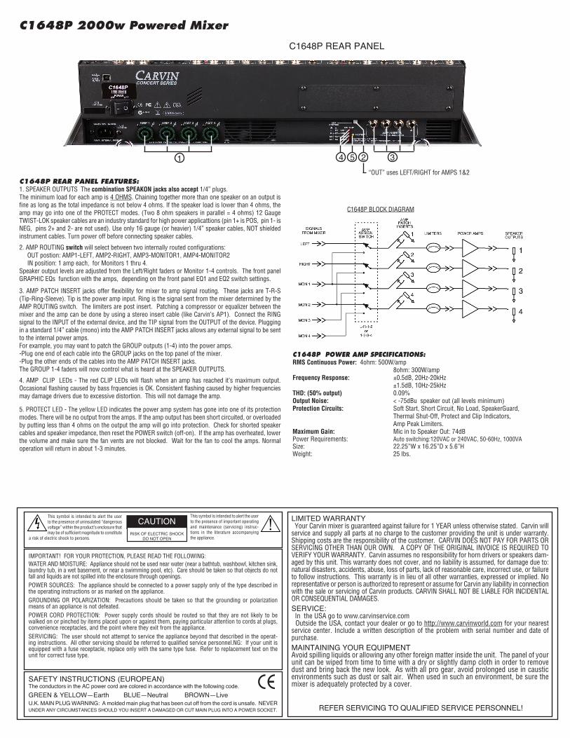
C1648P PowER AmP SPECiFiCATioNS:RMS Continuous Power: 4ohm: 500W/amp 8ohm: 300W/ampFrequency Response: ±0.5dB, 20Hz-20kHz ±1.5dB, 10Hz-25kHzTHD: (50% output) 0.09% Output Noise: < -75dBu speaker out (all levels minimum) Protection Circuits: Soft Start, Short Circuit, No Load, SpeakerGuard, Thermal Shut-Off, Protect and Clip Indicators, Amp Peak Limiters.Maximum Gain: Mic in to Speaker Out: 74dBPower Requirements: Auto switching:120VAC or 240VAC, 50-60Hz, 1000VASize: 22.25”W x 16.25”D x 5.6”HWeight: 25 lbs.
C1648P 2000w Powered mixer
“OUT” uses LEFT/RIGHT for AMPS 1&2
254 3
C1648P BLOCK DIAGRAM
CARVIN ENGINEERING DATA C1648, C2448, C3248, C1648P 4-bus MIXER OPERATING MANuAL
76-02448a 0210
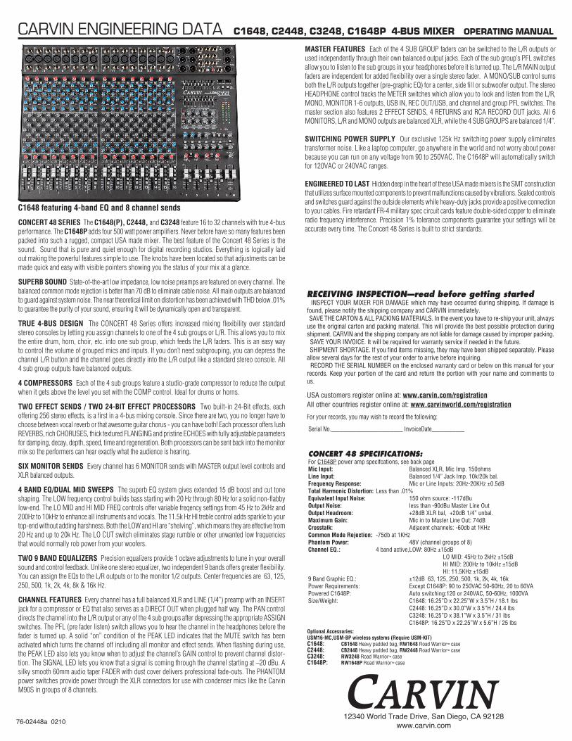
C1648 featuring 4-band EQ and 8 channel sends
CONCERT 48 SERIES The C1648(P), C2448, and C3248 feature 16 to 32 channels with true 4-bus performance. The C1648P adds four 500 watt power amplifiers. Never before have so many features been packed into such a rugged, compact USA made mixer. The best feature of the Concert 48 Series is the sound. Sound that is pure and quiet enough for digital recording studios. Everything is logically laid out making the powerful features simple to use. The knobs have been located so that adjustments can be made quick and easy with visible pointers showing you the status of your mix at a glance.
SUPERB SOUND State-of-the-art low impedance, low noise preamps are featured on every channel. The balanced common mode rejection is better than 70 dB to eliminate cable noise. All main outputs are balanced to guard against system noise. The near theoretical limit on distortion has been achieved with THD below .01% to guarantee the purity of your sound, ensuring it will be dynamically open and transparent.
TRUE 4-BUS DESIGN The CONCERT 48 Series offers increased mixing flexibility over standard stereo consoles by letting you assign channels to one of the 4 sub groups or L/R. This allows you to mix the entire drum, horn, choir, etc. into one sub group, which feeds the L/R faders. This is an easy way to control the volume of grouped mics and inputs. If you don’t need subgrouping, you can depress the channel L/R button and the channel goes directly into the L/R output like a standard stereo console. All 4 sub group outputs have balanced outputs.
4 COMPRESSORS Each of the 4 sub groups feature a studio-grade compressor to reduce the output when it gets above the level you set with the COMP control. Ideal for drums or horns.
TWO EFFECT SENDS / TWO 24-BIT EFFECT PROCESSORS Two built-in 24-Bit effects, each offering 256 stereo effects, is a first in a 4-bus mixing console. Since there are two, you no longer have to choose between vocal reverb or that awesome guitar chorus - you can have both! Each processor offers lush REvERBS, rich CHORUSES, thick textured fLANgINg and pristine ECHOES with fully adjustable parameters for damping, decay, depth, speed, time and regeneration. Both processors can be sent back into the monitor mix so the performers can hear exactly what the audience is hearing.
SIX MONITOR SENDS Every channel has 6 MONITOR sends with MASTER output level controls and XLR balanced outputs.
4 BAND EQ/DUAL MID SWEEPS The superb EQ system gives extended 15 dB boost and cut tone shaping. The LOW frequency control builds bass starting with 20 Hz through 80 Hz for a solid non-flabby low-end. The LO MID and HI MID fREQ controls offer variable freqency settings from 45 Hz to 2kHz and 200Hz to 10kHz to enhance all instruments and vocals. The 11.5k Hz HI treble control adds sparkle to your top-end without adding harshness. Both the LOW and HI are “shelving”, which means they are effective from 20 Hz and up to 20k Hz. The LO CUT switch eliminates stage rumble or other unwanted low frequencies that would normally rob power from your woofers.
TWO 9 BAND EQUALIZERS Precision equalizers provide 1 octave adjustments to tune in your overall sound and control feedback. Unlike one stereo equalizer, two independent 9 bands offers greater flexibility. You can assign the EQs to the L/R outputs or to the monitor 1/2 outputs. Center frequencies are 63, 125, 250, 500, 1k, 2k, 4k, 8k & 16k Hz.
CHANNEL FEATURES Every channel has a full balanced XLR and LINE (1/4”) preamp with an INSERT jack for a compressor or EQ that also serves as a DIRECT OUT when plugged half way. The PAN control directs the channel into the L/R output or any of the 4 sub groups after depressing the appropriate ASSIgN switches. The PfL (pre fader listen) switch allows you to hear the channel in the headphones before the fader is turned up. A solid “on” condition of the PEAK LED indicates that the MUTE switch has been activated which turns the channel off including all monitor and effect sends. When flashing during use, the PEAK LED also lets you know when to adjust the channel’s gAIN control to prevent channel distor-tion. The SIgNAL LED lets you know that a signal is coming through the channel starting at –20 dBu. A silky smooth 60mm audio taper fADER with dust cover delivers professional fade-outs. The PHANTOM power switches provide power through the XLR connectors for use with condenser mics like the Carvin M90S in groups of 8 channels.
RECEiViNG iNSPECTioN—read before getting started INSPECT YOUR MIXER FOR DAMAGE which may have occurred during shipping. If damage is found, please notify the shipping company and CARVIN immediately. SAVE THE CARTON & ALL PACKING MATERIALS. In the event you have to re-ship your unit, always use the original carton and packing material. This will provide the best possible protection during shipment. CARVIN and the shipping company are not liable for damage caused by improper packing. SAVE YOUR INVOICE. It will be required for warranty service if needed in the future. SHIPMENT SHORTAGE. If you find items missing, they may have been shipped separately. Please allow several days for the rest of your order to arrive before inquiring. RECORD THE SERIAL NUMBER on the enclosed warranty card or below on this manual for your records. Keep your portion of the card and return the portion with your name and comments to us.
USA customers register online at: www.carvin.com/registrationAll other countries register online at: www.carvinworld.com/registration
For your records, you may wish to record the following:
Serial No.________________________ InvoiceDate___________
MASTER FEATURES Each of the 4 SUB gROUP faders can be switched to the L/R outputs or used independently through their own balanced output jacks. Each of the sub group’s PfL switches allow you to listen to the sub groups in your headphones before it is turned up. The L/R MAIN output faders are independent for added flexibility over a single stereo fader. A MONO/SUB control sums both the L/R outputs together (pre-graphic EQ) for a center, side fill or subwoofer output. The stereo HEADPHONE control tracks the METER switches which allow you to look and listen from the L/R, MONO, MONITOR 1-6 outputs, USB IN, REC OUT/USB, and channel and group PfL switches. The master section also features 2 EffECT SENDS, 4 RETURNS and RCA RECORD OUT jacks. All 6 MONITORS, L/R and MONO outputs are balanced XLR, while the 4 SUB gROUPS are balanced 1/4”.
SWITCHING POWER SUPPLY Our exclusive 125k Hz switching power supply eliminates transformer noise. Like a laptop computer, go anywhere in the world and not worry about power because you can run on any voltage from 90 to 250vAC. The C1648P will automatically switch for 120vAC or 240vAC ranges.
ENGINEERED TO LAST Hidden deep in the heart of these USA made mixers is the SMT construction that utilizes surface mounted components to prevent malfunctions caused by vibrations. Sealed controls and switches guard against the outside elements while heavy-duty jacks provide a positive connection to your cables. fire retardant fR-4 military spec circuit cards feature double-sided copper to eliminate radio frequency interference. Precision 1% tolerance components guarantee your settings will be accurate every time. The Concert 48 Series is built to strict standards.
Optional Accessories:USM16-MC,USM-BP wireless systems (Require USM-KIT)C1648: CB1648 Heavy padded bag, RW1648 Road Warrior™ caseC2448: CB2448 Heavy padded bag, RW2448 Road Warrior™ caseC3248: RW3248 Road Warrior™ caseC1648P: RW1648P Road Warrior™ case
CoNCERT 48 SPECiFiCATioNS:For C1648P power amp specifcations, see back pageMic Input: Balanced XLR, Mic Imp. 150ohmsLine Input: Balanced 1/4” Jack Imp. 10k/20k bal.Frequency Response: Mic or Line Inputs: 20Hz-20KHz ±0.5dBTotal Harmonic Distortion: Less than .01% Equivalent Input Noise: 150 ohm source: -117dBuOutput Noise: less than -90dBu Master Line OutOutput Headroom: +28dB XLR bal, +20dB 1/4” unbal.Maximum Gain: Mic in to Master Line Out: 74dBCrosstalk: Adjacent channels: -60db at 1KHzCommon Mode Rejection: -75db at 1KHzPhantom Power: 48V (channel groups of 8)Channel EQ.: 4 band active, LOW: 80Hz ±15dB LO MID: 45Hz to 2kHz ±15dB HI MID: 200Hz to 10kHz ±15dB HI: 11.5KHz ±15dB9 Band Graphic EQ.: ±12dB 63, 125, 250, 500, 1k, 2k, 4k, 16kPower Requirements: Except C1648P: 90 to 250VAC 50-60Hz, 20 to 60VAPowered C1648P: Auto switching:120 or 240VAC, 50-60Hz, 1000VASize/Weight: C1648: 16.25”D x 22.25”W x 3.5”H / 18.1 lbs C2448: 16.25”D x 30.0”W x 3.5”H / 24.4 lbs C3248: 16.25”D x 38.1”W x 3.5”H / 31 lbs C1648P: 16.25”D x 22.25”W x 5.6”H / 25 lbs
12340 World Trade Drive, San Diego, CA 92128www.carvin.com
C48 SERiES CoNTRoLSChANNEL FEATURES1. 1/4” LiNE iNPUTSThe line connectors are for connecting balanced and unbal-anced instruments and line level sources such as drum machines, keyboards, ETC.
2. XLR miC iNPUTS The balanced Mic inputs are for connecting microphones that use XLR connections. Both the LINE and XLR MIC inputs can be used simultaneously.
3. ChANNEL iNSERT/diRECT oUTTo insert channel effects, compressor, etc. use a 1/4” TRS (Tip Ring Sleeve) cable (see INSERTS AND DIRECT OUT illustration on page 5 for TRS details). To achieve a direct out from the channel, insert a standard 1/4” cable to the first “click” (1/2 insert).
4. GAiN The gain controls the input level for the channel. If the gain is set too high, the PEaK LED will flash and distortion may occur. Decrease the amount of gain until the PEaK LED does not flash. It is important that the gain control should be kept next to the PEAK LED flash point to maintain the lowest noise of the channel. You can use the channel PFL switch to monitor the channel input level and use the meters to adjust the gain control to 0dB. This will give a good reference where the GAIN control should be set.
5. Low CUT SwiTChA 75 Hz Low cut filter helps eliminate unwanted low frequen-cies. Great for reducing “boom” noise from mic stands or from acoustic/electric guitars. Turning up the Low EQ when using this filter can help create a punchier bass response.
6. ACTiVE 4 bANd EQ wiTh dUAL mid SwEEPSThe C48 SERIES mixers provide studio EQ. The ±15 dB boost or cut gives an overall 30 dB range for powerful EQ control. The active circuits deliver deep bass from the 20-80 Hz Low control. The MiD controls work at 45Hz to 10kHz, depend-ing on the MiD FREQ controls. The Hi control functions at 11-20k for crisp highs. Start out with all tone controls at their center “zero” position. Determine which position your MID FREQ sounds best, then cut or boost your Hi, HI MiD, Lo MiD, and Low frequencies as needed. If you are trying to mic instruments such as acoustic guitar or drums, try various mics and mic placement before adjusting your tone controls. A typical setting may be: HI -3, HI MID+5 (MID FREQ set at 4kHz), LO MID -4 (MID FREQ set at 700Hz), and LOW +3. Don’t be afraid to adjust the HI and LOW controls to get good presence and depth while reducing the LO MIDs to clean up your sound. This is one of the keys to great sound.
7. hi & Lo mid SwEEPSThese controls allow you to select which frequency (from 200Hz-10kHz or 45Hz-2kHz) that the MiD controls will boost or cut. By adjusting the MiD FREQs, you can select the exact
frequency that will best complement various inputs. 700Hz and 4kHz are recommended settings for the MiD FREQ control for guitar and vocals.
8. moNiToR 1 ThRU 6 SENd CoNTRoLSThe channel MONITOR controls allow you to create six independent monitor mixes. The MONITOR signals (pre-EQ, pre fader) are routed to the master MON 1, 2, 3, 4, 5 and 6 controls (#22) respectively before going to the XLR output connectors (#40).
9. EFF 1 & EFF 2 SENd CoNTRoLSThe EFF 1 or EFF 2 control sends signal (post EQ, post fader) from the channel to the master EFFEctS 1 or EFFEctS 2 levels to the internal processors (#18) and to the EFF 1 or EFF 2 output (#38).
10. PAN CoNTRoL Each channel’s Pan control allows stereo imaging by pan-ning Left or Right during recordings or live performances. The Pan control also works for the sub-mix groups. A center position will send a channel’s signal to a pair of sub-group faders (1-2, 3-4 when assigned). By panning hard left, the signal is routed to only sub-group fader 1 or 3 when assigned. Panning hard right routes the signal to sub-mix fader 2 or 4. Dual element pan controls provide 15dB greater separation than standard pan controls
11. ChANNEL SiGNAL GREEN LEd The SignaL LED is pre-fader and post EQ. This LED helps the operator verify that the channel is receiving a signal from the mic or instrument inputs even when the channel fader is off.
12. ChANNEL REd PEAK LEd This peak indicator is pre-fader and post EQ. If the PEaK LED flashes, the channel needs a reduction with the gain control (#4) to prevent distortion. A “solid” lit PEaK LED indicates that the channel has been MUTED.
13. ChANNEL mUTE SwiTCh The MutE switch will interrupt the channel signal. This feature saves having to reset your faders and monitor sends. The PEAK LED will light solid ON with no SIG LED.
14. ChANNEL PFL SwiTCh This switch allows the operator to listen to a channel (pre fader listen) in the headphone mix to set tone and gain levels as well as see the channel at the LED meter output (#33).
15. ChANNEL ASSiGNmENT SwiTChESThese switches assign the channels’ signal to the Master L/R faders, or to the Sub-gRouP faders 1 & 2, 3 & 4 for sub-mixing in stereo pairs. For mono, PAN fully to the left and assign a channel to Sub-Group fader 1 or 3 only. PAN fully to the right and assign a channel to Sub-Group fader 2 or 4. Likewise assigning the L/R switches sends the channel directly to the main L or R faders.
16. ChANNEL FAdER The CHANNEL FADER adjusts the output level of the chan-nel. The signal will go to one or more of the Master Faders, depending on both the Channel Assignment switches and the Pan control. Calibrated 60mm FaDERS with audio tapers are
featured for smooth fade-outs. Slide all faders down when connecting your inputs.17. miC PhANTom PowER SwiTCh / REd LEd This switch provides +48v power for condenser mics such as Carvin’s CM90E in groups of 8 channels. This leaves the remaining MIC inputs for sources that don’t require phantom power. The LINE inputs are unaffected.
mASTER SECTioN18. dUAL STEREo 24-biT EFFECTS PRoCESSoR The internal 24-BIT stereo processors receive signals from the channel EFF1 and EFF2 controls and the master EFF1 and EFF2 controls. If the adjacent PK (peak) LED flashes, reduce the level from the channel or master EFF1 or EFF2 send controls. A “solid” PK LED will show EFFEctS 1 or 2 have been muted by the MutE switches. The RETURN control will adjust the volume level of the selected effects. Remember each channel has its own two EFFECT sends that will send the signal to the effects processors. The red PK LED will indicate when the effects signal from the channel is distorting. Reduce the level of the channel EFFECT control until the PK LED stops flashing. EFFECT AND PARAMETERSa.)ECHO: When the SELECT control is at the “seven O-clock” position, it is selected to the first ECHO setting where you get a single repeat echo (minimal regeneration). Turning the PARAMETER control to 1 will provide the shortest delay time between the original signal and the echo. Increasing the PARAMETER control to the right will increase the time delay between the original signal and the echo. To increase the number of echo repeats, turn the SELECT control clockwise to “9 O-clock” (maximum regeneration).
b.)REVERB: When the SELECT control is at the “ten O-clock” position, it is selected to the first REVERB setting. Turning the SELECT control clockwise will increase the amount of high frequencies in the reverb. Turning the PARAMETER control to 1 will provide minimal decay time of the reverb. Increasing to the right will increase the reverb decay time.
c.)CHORUS: When the SELECT control is at the “one O-clock” position it is selected to the first CHORUS setting. Turning the SELECT control clockwise will increase the amount reverb in the chorus. Turning the PARAMETER control to 1 will provide a minimal chorus depth setting. Increasing to the right will increase the chorus depth.
d.)FLANGE: When the SELECT control is at the “four O-clock” position it is selected to the first FLANGE setting. Turning the SELECT control clockwise will increase the flanger’s speed. Turning the PARAMETER control to 1 will provide minimal flanging depth. Increasing to the right will increase the flanger’s depth.
To send effects to the monitors, use the “to MonitoRS” controls, Mon 1/Mon 2 & Mon 1/Mon 3. The center posi-tion on both controls is OFF.
19. SEND 1 & 2 Sends signals from the channel EFF 1 and EFF2 controls to the internal processors and to the EFF1 and EFF2 output jacks.
20. RETURN 3 L-R Receives stereo or 2 mono effect signals from the REtuRn 3 L /R jacks. These signals will also be present at Mon 1 (#40).
21. RETURN 4 L-R/ USb iNReceives a signal from the Rtn 4 L/R 1/4” jacks (#39) and from the rear uSb port. These signals will also be present at Mon 1.
22. moNiToR 1-6 CoNTRoLS These are the master outputs for the six monitor sends. These correspond to the MON 1-6 XLR output jacks (#40).23. GRoUP/SUb-miX FAdERS 1-4Once a channel has been assigned to one of these faders, the mixing process is simplified to using these four faders. If these faders are not assigned to the Master L-R faders (#28), then each fader is bused to the corresponding 4 GROUP 1/4” outputs (#41). By assigning the 4 faders to the Master L-R faders, the operator can use the faders to sub-mix groups.
QUiCK START UPIf you’re like most new owners, you’re probably in a hurry to plug your mixer in and use it. Here are some brief instructions to get you going quickly. With the mixer unplugged and the unit turned off, complete the following procedures:
1. CONNECTING AC POWER TO YOUR MIXER• The mixer can be used with 120 or 240VAC (it automati-cally switches internally) • Use only a grounded (3 prong) power outlet to prevent a shock hazard. This gives the quietest grounding for your mixer.
2. CONNECTING INPUTS TO YOUR MIXER• For low level balanced devices such as microphones, plug into the balanced MIC inputs using a shielded microphone cable with XLR connectors.
• For high level balanced or unbalanced devices such as instruments & keyboards, plug into the LINE input jacks using a shielded cable with 1/4” phone plugs. Adjust the GAIN knob for the mic or line input being used.
3. TURNING YOUR MIXER ON• Adjust all channel FADERS and master LEVEL controls to their OFF positions • Adjust all channel’s HI, MID, and BASS controls and the two master 9 Band GRAPHICS to their center positions.• Adjust the Channel “PAN” controls to their center posi-tions. • Turn the mixer on by the rear panel POWER SWITCH and watch for the POWER LED. Your mixer is now ready to operate.
C1648, C2448, C3248 & C1648P 4-bUS miXERS
2
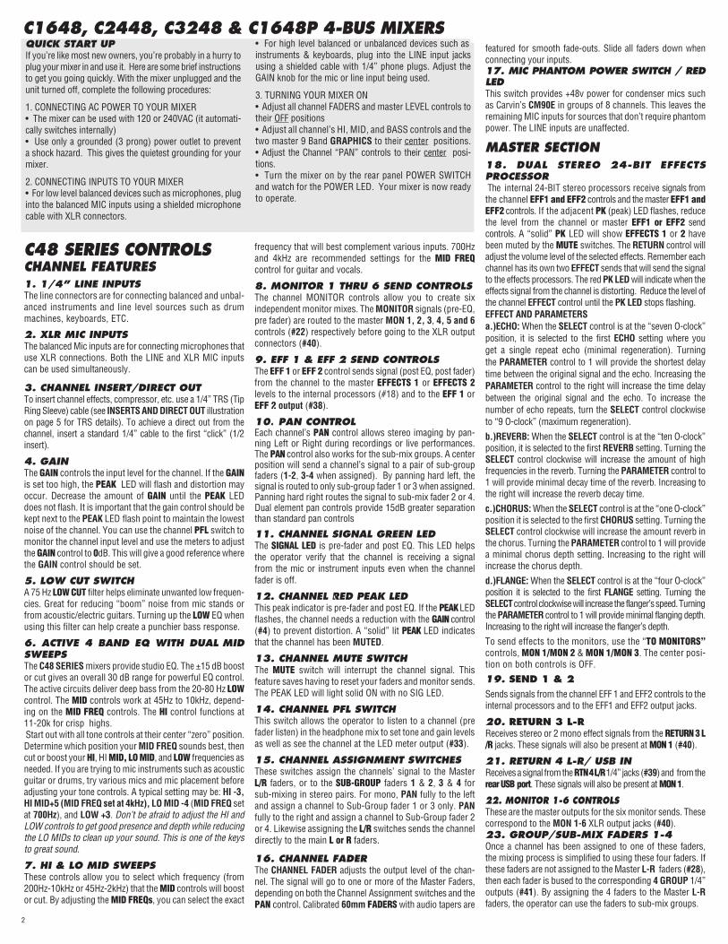
24. GRoUP PFL SwiTChES These PFL switches allow the operator to monitor the entire GROUP mix. If distortion is heard or if the PFL level is near PEAK on the Master L/R MEtERS, lower the channel faders assigned to that group. Also check the channel PEaK LEDs.
25. GRoUP ASSiGNmENT SwiTChES These switches send the sub-group mix to the main L/R faders. For mono mixing, assign to both L/R.
26. ComP 1-4 GRoUP ComPRESSoRS / LEds Each of the 4 sub groups features a compressor, which will reduce the output when it gets above the level you set with
the COMP control. Set at “0” there is no effect. As you turn UP the COMP knob, the lower the maximum level. The compressor circuit is pre-fader, so you can set the COMP once and still adjust the group fader as needed. The LED will indicate when the compressor is working.
27. ComP LiNK SwiTChES These switches link the COMP controls for stereo pairs of equal setting. The COMP1 or COMP3 control becomes the master for the pair. Link 1-2 or 3-4.
28. mASTER L/R FAdERS These faders adjust the level of the main stereo output created by all channels and groups assigned to L/R faders. Output appears at the L/R balanced XLR connectors (#44).
29. moNo/SUb CoNTRoLA mono output is created from the L/R master faders (post) for center, subwoofers, or side fill speakers. The output is at the Mono/SUB XLR connector (#45).
30. REC oUT/USb CoNTRoLThis control sets the level sent to REC OUT L-R RCA jacks and to the rear USB port. The signal source is the main L-R mix (pre-fader).
31. hEAdPhoNE ANd mETER SoURCEThe stereo PHonES control sets the level of the PHonES jack (#42). The PFL, L/R, Mono, Mon 1-Mon 6, uSb in, and REc out uSb switches allow for monitoring of these sources through the headphones and the L/R LED METERS (#33).
32. PFL REd LEd Indicates that the headphone & meters are monitoring only the channels or groups where the PFL is switched on.
33. L/R LEd VU mETERS This group of 10 LED’s offer 6 dB increment resolution that give the operator a visual indica-tion of the mixer’s output levels, selectable by the METER SOURCE or PFL switches (#31).
34. dUAL PRECiSioN 9 bANd GRAPhiC EQs are one octave filters at 60,125, 250, 500, 1k, 2k, 4k, 8k & 16k Hz centers that offer ±12dB adjustment to help eliminate feedback & enhance tone for the main or monitor mix.
35. EQ SwiTCh 1 & 2 These switches swap the 9 band EQ’s from the standard L/R main outputs “OUT” to the MON 1 & MON 2 outputs “IN” respectively.
36. USb PowER PoRTSUse these ports to supply +5V USB power to run accessories like LED lighting or to charge MP3 players. Connect audio outputs to RETURNS 3 or 4, or to channel inputs.
37. PowER bLUE LEd Verifies the mixer is on.
38. EFFECTS 1 & 2 oUTPUT JACKS 1/4” outputs drive external effects. Connect your effects processor’s inputs to these jacks.
39. RETURNS 3 & 4 L-R iNPUT JACKSReturns a stereo signal from an external effect. Connect your effects processors’ stereo outputs to these jacks. If only one jack is used, the mono signal will go to both L/R .
40. moNiToR 1-6 XLR oUTPUT CoNNECToRSThe C48 SERIES provides balanced XLR outputs. Connect your monitor power amps to these connectors.
41. GRoUP 1-4 oUTPUT JACKSThe C48 SERIES provides 4 balanced 1/4” outputs. Connect your 4-track recorder or side fill power amps to these jacks.
42. hEAdPhoNE JACK 1/4” stereo jack for headphone or control room output.
43. REC oUT L-R RCA JACKSRCA jacks for connecting to a recorder input.
44. LEFT & RiGhT XLR oUTPUT CoNNECToRS This set of balanced XLR connectors are for connecting the main L/R output to power amps or recording gear.
45. moNo/SUb XLR oUTPUT CoNNECToR A balanced XLR output is featured for side fills or subwoof-ers.
46. REAR USb CoNNECToR This rear USB connector will transmit audio to and from a computer for recording with compatible software and driv-ers. Output signal is the pre-fader L-R stereo mix sent via the REC OUT USB LEVEL. Input from a computer comes into the RETURN 4 bus, controlled at the RTN4/USB control.
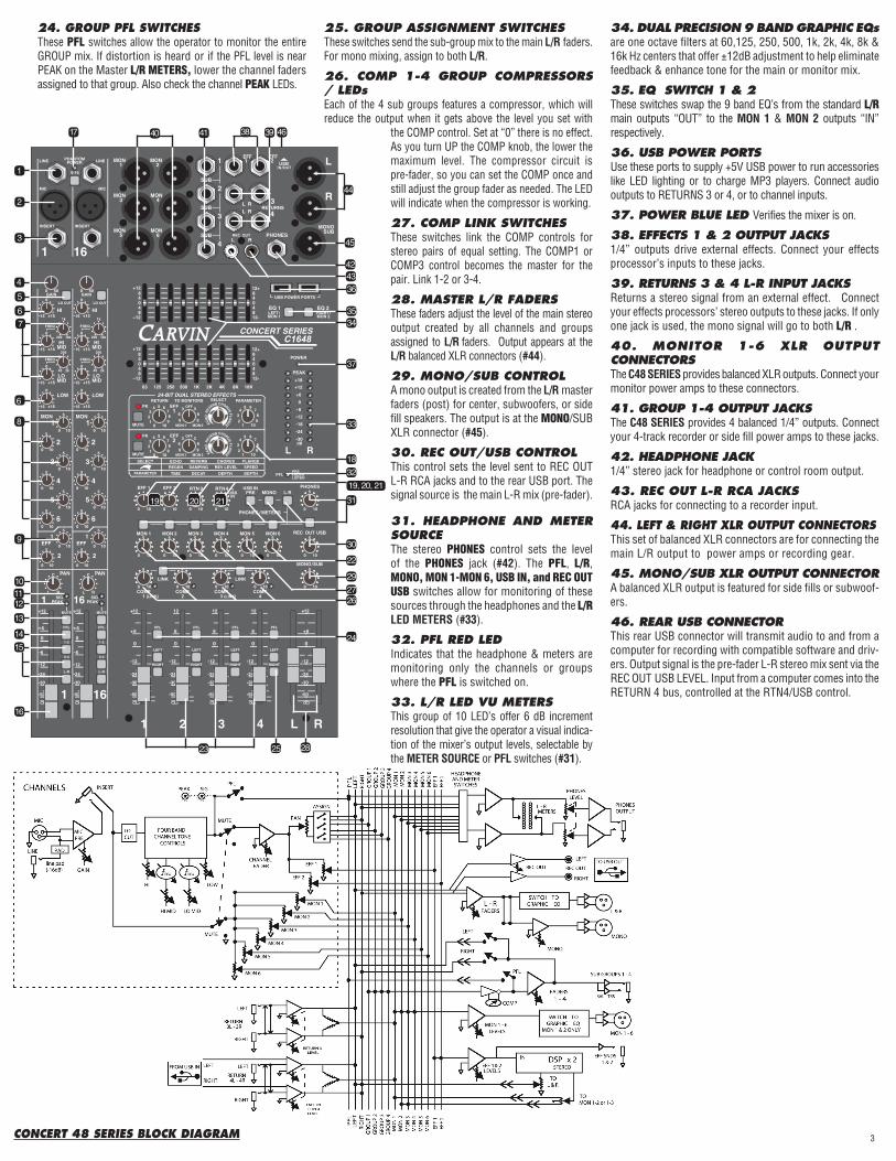
3CoNCERT 48 SERiES bLoCK diAGRAm
1
17 40 41
2
3
45
7
8
9
1011121314
16
6
4342
45
36
25 28
39 4638
6
15
44
35
37
33
22
30
31
32
34
29
2627
24
23
18
20 211919, 20, 21