Embed Size (px)
Citation preview

8/9/2019 Machine Elements Assignment
http://slidepdf.com/reader/full/machine-elements-assignment 1/22
1
TABLE OF CONTENTS
Acknowledgements ……………………………………………………………………………….. 02
Introduction …………………………………………………………………………………………… 03
The Automobile Differential ………………………………………………………………….. 04-08
Introduction …………………………………………………………………………………………………… 04
Inputs and Outputs, paths of power transmission
and possible power losses in a differential …………………………………………………….. 05-06
Reasons for using the specific machine elements …………………………………………… 07
Drawbacks and Improvements for a differential …………………………………………….. 08
Washing Machine ………………………………………………………………………..…….…… 09-15
Introduction ………………………………………………………………………………………..…………… 09
Inputs and Outputs, paths of power transmission
and possible power losses in a washing machine……………………….……..…..……….. 10-13
Reasons for using the specific machine elements …………………………...……………… 13-14
Drawbacks and Improvements for a washing machine ………………….……………….. 15
Lockstitch Machine ……………………………………………………………………..…….…… 16-22
Introduction ………………………………………………………………………………………..…….…… 16-17
Inputs and Outputs, paths of power transmissionand possible power losses in a lockstitch machine……………….…….……..…..……….. 18-19
Reasons for using the specific machine elements …………………………...……………… 20
Drawbacks and Improvements for a lockstitch machine ……………….…….…………… 21-22

8/9/2019 Machine Elements Assignment
http://slidepdf.com/reader/full/machine-elements-assignment 2/22
2
ACKNOWLEDGEMENTS
First off our heartiest gratitude to our subject coordinator for Textile Machinery and
Instrumentation, Ms. V. S. Rathnayake for providing us with this opportunity to gain extraneous
knowledge regarding the subject. We were provided with the right knowledge, assistance and an
insight as to what needs be done from her experienced point of view. Furthermore, many a
thanks to the lecturers and the technical staff of the Department of Textile and Clothing
Technology of University of Moratuwa for the assistance provided with the machines in the
clothing lab. Finally, a vote of thanks for the group members and our friends who helped us in
every possible way.

8/9/2019 Machine Elements Assignment
http://slidepdf.com/reader/full/machine-elements-assignment 3/22
3
INTRODUCTION
In automobiles and other wheeled vehicles, a differential couples the drive shaft to half-shafts
that connect to the rear driving wheels. The differential gearing allows the outer drive wheel to
rotate faster than the inner drive wheel during a turn. This is necessary when the vehicle turns,
making the wheel that is travelling around the outside of the turning curve roll farther and fasterthan the other. Average of the rotational speed of the two driving wheel equals the input
rotational speed of the drive shaft. An increase in the speed of one wheel is balanced by a
decrease in the speed of the other. A differential consists of one input, the drive shaft, and two
outputs which are the two drive wheels, however the rotation of the drive wheels are coupled
by their connection to the roadway. Under normal conditions, with small tire slip, the ratio of the
speeds of the two driving wheels is defined by the ratio of the radii of the paths around which
the two wheels are rolling, which in turn is determined by the track-width of the vehicle (the
distance between the driving wheels) and the radius of the turn.
A washing machine (laundry machine, clothes washer, or washer) is a machine to wash laundry,
such as clothing and sheets. The term is mostly applied only to machines that use water as
opposed to dry cleaning (which uses alternative cleaning fluids, and is performed by specialist
businesses) or ultrasonic cleaners. Washing entails immersing, dipping, rubbing, or scrubbing in
water usually accompanied by detergent, or bleach. The simplest machines may simply agitate
clothes in water; automatic machines may fill, empty, wash, spin, and heat in a cycle. Most
washing machines remove substantial amounts of water from the laundry at the end of a wash
cycle, but do not completely dry it.
Sewing machines are something like cars: There are hundreds of models on the market, and
they vary considerably in price and performance. At the low-end of the scale, there are
conventional no-frills electric designs, ideal for occasional home use; at the high-end, there aresophisticated electronic machines that hook up to a computer. Textile companies have many
machines to choose from, including streamlined models specifically designed to sew one
particular product. But just like cars, most sewing machines are built around one basic idea.
Where the heart of a car is the internal, the heart of a sewing machine is the loop stitching
system, the lock stitch.

8/9/2019 Machine Elements Assignment
http://slidepdf.com/reader/full/machine-elements-assignment 4/22
4
AUTOMOBILE DIFFERENTIAL
INTRODUCTION
The differential is simply a device that splits the engine torque two ways, allowing each output
to spin at a different speed. The differential is found on all modern cars and trucks, and also in
many all-wheel-drive vehicles. Automobile differentials serve three main purposes, namely;
Aiming the engine power at the wheels Acting as the final gear reduction in the vehicle, slowing the rotational speed of the
transmission one final time before it hits the wheels Transmitting the power to the wheels while allowing them to rotate at different speeds
There are a number of automobile differentials according to the mechanism used. The most
common are;
Open Differentials
Locking Differentials
Limited Slip Differentials(LSD)
Where the open differential always balances the torque between the 2 wheels whereas, locking
differentials adapt to resistance and the LSD (Limited Slip Differential) is a compromise of the 2.
Each have their own advantages and disadvantages.
The third purpose mentioned above is what has earned the differential its name. Since it allows
2 wheels connected to it to be rotated at 2 different speeds. In this section of the report, the
following points shall be taken into account;
Inputs and outputs of a differential
Paths of power transmissions and possible power losses
Reasons for using those machine elements
Drawbacks of a differentials
Improvements to a differential
Furthermore, this differential principle can be applied to front-wheel-drive vehicles, rear-wheel-
drive vehicles and also for all-wheel-drive vehicles. For front wheel and rear wheel drives there
shall be only two side axles connecting to wheels whereas in all-wheel-drive vehicles 4 side axles
need to be connected. These all-wheel-drive vehicles need a differential between each set of
drive wheels, and they need one between the front and the back wheels as well, because thefront wheels travel a different distance through a turn than the rear wheels.

8/9/2019 Machine Elements Assignment
http://slidepdf.com/reader/full/machine-elements-assignment 5/22
5
INPUTS AND OUTPUTS, PATHS OF POWER TRANSMISSION AND POSSIBLE POWER
LOSSES IN AN AUTOMOBILE DIFFERENTIAL
In order to completely describe the mechanism of an automobile differential or to put it more
simply, a differential, the following diagram including the basic machine elements shall be used.
Note that this is just a rough sketch and teeth in gearing are usually not parallel teeth.
Car wheels spin at different speeds, especially when turning. Each wheel travels a different
distance through the turn, and that the inside wheels travel a shorter distance than the outsidewheels. Since speed is equal to the distance traveled divided by the time it takes to go that
distance, the wheels that travel a shorter distance travel at a lower speed. Also note that the
front wheels travel a different distance than the rear wheels.
The power generated in the engine is first transmitted to the gear box, and then to the main axle.
Just before the high rotating speeds of the axle hit the epicyclic gear train in the differential, this
provides the final gear reduction, slowing the rotational speed of the transmission one final time.
An illustration is shown below.
KEY
1. Crown/Ring Gear
2. Pinion Gear
8/9/2019 Machine Elements Assignment
http://slidepdf.com/reader/full/machine-elements-assignment 6/22
6
As shown in the figure above the teeth ratio Pinion gear: Ring gear is rather a small value, thus
resulting in a reduction of high rotational speeds. This also splits the amount of torque
transmitted to each wheel. Hence the input is the pinion gear connected to the main axle and
the output is the rotation of wheels, sometimes in different speeds.
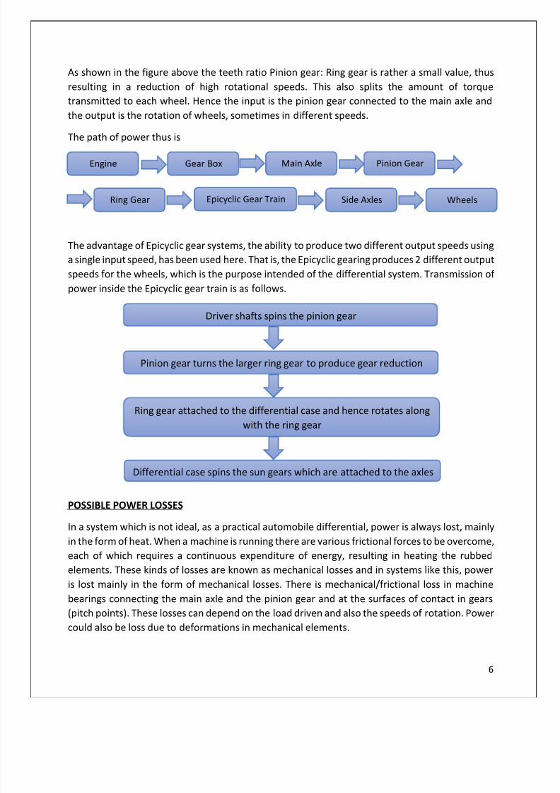
The path of power thus is
The advantage of Epicyclic gear systems, the ability to produce two different output speeds using
a single input speed, has been used here. That is, the Epicyclic gearing produces 2 different output
speeds for the wheels, which is the purpose intended of the differential system. Transmission ofpower inside the Epicyclic gear train is as follows.
POSSIBLE POWER LOSSES
In a system which is not ideal, as a practical automobile differential, power is always lost, mainly
in the form of heat. When a machine is running there are various frictional forces to be overcome,
each of which requires a continuous expenditure of energy, resulting in heating the rubbedelements. These kinds of losses are known as mechanical losses and in systems like this, power
is lost mainly in the form of mechanical losses. There is mechanical/frictional loss in machine
bearings connecting the main axle and the pinion gear and at the surfaces of contact in gears
(pitch points). These losses can depend on the load driven and also the speeds of rotation. Power
could also be loss due to deformations in mechanical elements.
Engine Gear Box Main Axle Pinion Gear
Ring Gear Epicyclic Gear Train Side Axles Wheels
Driver shafts spins the pinion gear
Pinion gear turns the larger ring gear to produce gear reduction
Ring gear attached to the differential case and hence rotates along
with the ring gear
Differential case spins the sun gears which are attached to the axles

8/9/2019 Machine Elements Assignment
http://slidepdf.com/reader/full/machine-elements-assignment 7/22
7
REASONS FOR USING THE SPECIFIC MACHINE ELEMENTS
I. Non-parallel teeth in the gears in the bevel gear system:
Improved gear mesh due to greater gear-tooth contact area.
Reduces Gear noise
Operates smoother than spur gearsProlonged machine life
II. Epicyclic gear train:
To produce 2 different output speeds for two wheels.
III. Gear Drives:
Because high amounts of power and torque are transmitted and gears are more suitable
than belt drives for these high power transmissions.
Very high loads i.e. passengers are driven and gears can drive high amounts of loads.
Since constant transmission of power and torque is required and gears can provide this
option since there is no slippage.
Prolonged machine life since automobiles are intended for long term usage.
Ability to be used for a wide range of transmitted power since the power produced in
the engine can vary in a wide range.
IV. Bevel Gears:
To drive the crown or ring gear whose axis is perpendicular to the axis of the pinion gear
connected directly to the main axle.
V.
Bearings:In taking a bend, one wheel must have a higher speed than that of the other. Hence, it’s
necessary to allow constrained relative motion between the wheel and the side axle
where the bearing is used.
Bearing atthe pinion
gear
8/9/2019 Machine Elements Assignment
http://slidepdf.com/reader/full/machine-elements-assignment 8/22
8
DRAWBACKS AND IMPROVEMENTS OF DIFFERENTIALS
DRAWBACKS
I. Ring and pinion problems
Whining or howling noise that changes when going from acceleration to deceleration. Lack ofservice and low fluids can cause this problem.
If backlash (clearance) between the ring gear and the pinion gear is too great, a clunking sound
can be produced, especially when an automatic transmission is shifted into gear.
II. Bearings
Humming sounds get louder with speeds.
III. Mechanism
The torque transmitted to the two wheels with the open differential is the same. Consequently,if one wheel slips, as in ice or mud, the torque to the other wheel is reduced. The slipping wheel
receives all the torque.
IMPROVEMENTS
I. System should be properly lubricated and maintained in order to minimize ring and pinion
problems. I.e. fluid levels should be maintained at optimum levels. Vehicle should be subjected
to service in a timely manner.
II. Backlash should be adjusted to an optimum level. It is needed to allow for the heat expansion
and lubrication. Too little backlash will cause the gears to jam and too much backlash will causegear noise (whirring, roaring and clunking).
III. Normal/Open differentials have a disadvantage in the mechanism as explained above in the
previous section. Engineers have improved this technology to build locking differentials where
the side axle system is locked together and both of the wheels are forced to rotate at the same
speed without giving all the torque to the slipping wheel. Engineers have further improved these
technologies and have now come up with LSDs or Limited Slip Differentials, which is a
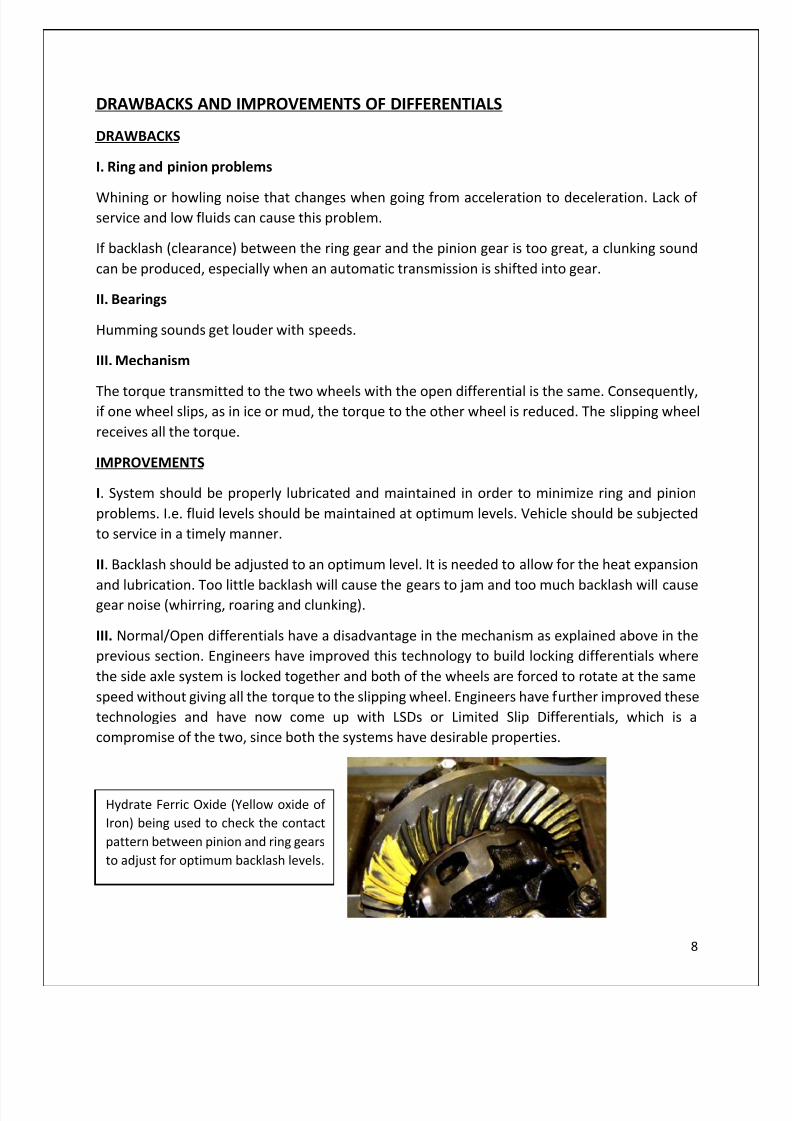
compromise of the two, since both the systems have desirable properties.
Hydrate Ferric Oxide (Yellow oxide of
Iron) being used to check the contact
pattern between pinion and ring gears
to adjust for optimum backlash levels.

8/9/2019 Machine Elements Assignment
http://slidepdf.com/reader/full/machine-elements-assignment 9/22
9
WASHING MACHINE
INTRODUCTION
This is a machine which uses to wash laundry, such as clothing and sheets.
When we are talking about the mechanical behavior of the washing machine it is a combination
of electric motor, which drives a heavy gear box and that is also attached to the steel inner tube.
The washing machine included two steel tubes. The inner tube holds the clothes. An agitator in
the middle of it, and the sides are perforated with holes. When the tub spins, the water can leave.
The other one is outer tube. It seals in all the water, is bolted to the body of the washer. The
inner tube is attached to the gearbox. When we are talking about the drive mechanism of
washing machine gear box is an important part.
The gear box is considered as one of the coolest parts of the washing machine. Some of the
mechanical elements inside the washing machine gear box are helical gears, Spur gear, Bevel
gears, pulleys and etc. If you spin the pulley on the gearbox one way, the inner shaft turns slowly
back and forth reversing direction about every half-revolution. If you spin the pulley the other
way, the flange spins at high speed, spinning the whole tub with it.
Inputs and outputs of a washing machine
Paths of power transmissions and possible power losses
Reasons for using those machine elements
Drawbacks of a washing machine
Improvements to a washing machine
will be the main topics we will consider in this
section of the dissertation.

8/9/2019 Machine Elements Assignment
http://slidepdf.com/reader/full/machine-elements-assignment 10/22
10
INPUTS AND OUTPUTS, PATHS OF POWER TRANSMISSION AND POSSIBLE POWER
LOSSES IN A WASHING MACHINE
GEAR BOX
When the washer goes into spin cycle, the whole mechanism locks up, causing everything to spinat the same speed as the input, which is hooked up to the motor. The interesting thing here is
that when the motor spins the gearbox in one direction, the agitator runs, and when it spins it
the other way, the whole machine locks up.
In the figure below there is a gear with angled teeth. There is also a smaller gear with angled
teeth behind the big one in the foreground. These are the only two gears with angled teeth.
Depending on which way the gears are spinning, the angle on the teeth will tend to force the
inner gear to slide either to the left or to the right inside the gearbox.
If it slides to the left, it engages a mechanism that locks up the gearbox.
We can see a small notch in the outer shaft. This notch is hollow, and is attached to the shaft
with the small helical gear. When the small gear moves, it moves this outer shaft with it, and the
small notch engages the single tooth that is fixed to the lockup mechanism. When the gearbox is
locked up, both the inner shaft, which drives the agitator, and the outer shaft, which drives the
tub, spin at the same speed as the input pulley. Also gear box is working under the direct drive
mechanism. It is one that takes the power coming from a motor without any reductions.
8/9/2019 Machine Elements Assignment
http://slidepdf.com/reader/full/machine-elements-assignment 11/22
11
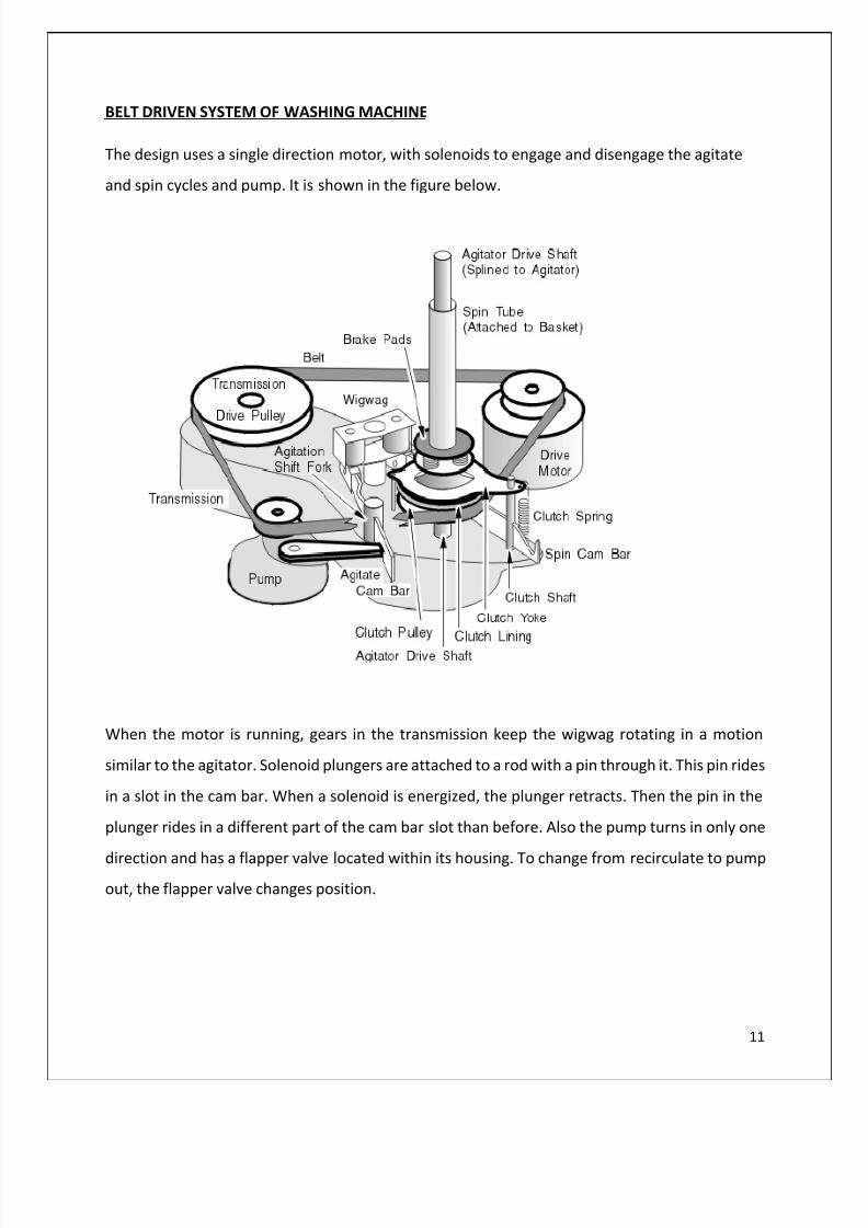
BELT DRIVEN SYSTEM OF WASHING MACHINE
The design uses a single direction motor, with solenoids to engage and disengage the agitate
and spin cycles and pump. It is shown in the figure below.
When the motor is running, gears in the transmission keep the wigwag rotating in a motion
similar to the agitator. Solenoid plungers are attached to a rod with a pin through it. This pin rides
in a slot in the cam bar. When a solenoid is energized, the plunger retracts. Then the pin in the
plunger rides in a different part of the cam bar slot than before. Also the pump turns in only one
direction and has a flapper valve located within its housing. To change from recirculate to pump
out, the flapper valve changes position.
8/9/2019 Machine Elements Assignment
http://slidepdf.com/reader/full/machine-elements-assignment 12/22
12
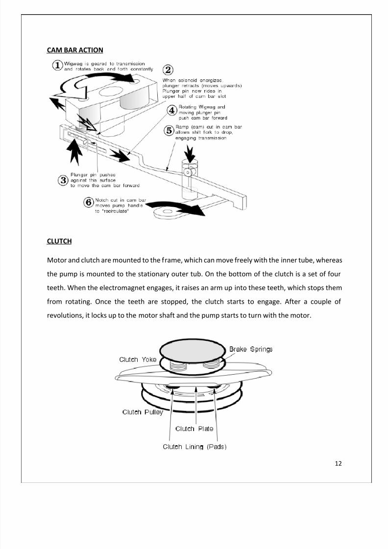
CAM BAR ACTION
CLUTCH
Motor and clutch are mounted to the frame, which can move freely with the inner tube, whereas
the pump is mounted to the stationary outer tub. On the bottom of the clutch is a set of four
teeth. When the electromagnet engages, it raises an arm up into these teeth, which stops them
from rotating. Once the teeth are stopped, the clutch starts to engage. After a couple of
revolutions, it locks up to the motor shaft and the pump starts to turn with the motor.

8/9/2019 Machine Elements Assignment
http://slidepdf.com/reader/full/machine-elements-assignment 13/22
13
The path of power transmission in a flow diagram
POSSIBLE POWER LOSSES
Mainly power is losses as the heat in washing machine as in any common mechanical system. But
it is working under direct drive mechanism. So power is less wasted in friction. It is an advantage.
Because of this mechanism it wants precise control. But in a system which is not ideal there is a
considerable power loss due to the friction in belt drives and pulleys also friction in gear drives.Also power is losses as the heat when gear box is being run. In washing machines, unlike in many
common systems, power is also lost as unnecessary vibrations. Although dampers as explained
above have been used in washing machines, washing machines in general, still create a
considerable amount of mechanical vibrations.
REASONS FOR USING THE SPECIFIC MACHINE ELEMENTS
1. Pulleys & Belt drives
Low maintenance since washing machines are not regularly serviced.
They are very simple and economical.
Noise & Vibration are damped out since a considerable noise can be generated in the
operation of a washing machine.
AgitatorShaft
BrakeDisk
TransmissionPulley
BeltTensioner
DriveMotor
Pump
8/9/2019 Machine Elements Assignment
http://slidepdf.com/reader/full/machine-elements-assignment 14/22
14
2. Gear Drives (Both Spur and Helical)
Since wet clothes and water can be very heavy loads and gear drives can supply this
demand, that is transmitting very high power and drive heavier loads.
It is used for a wide range of transmitted power since different speeds in washing are
used which require a range of power transmission.
Since various constant speeds are used in these machines, it needs a constant power
transmission. Gears provide this facility since there is no slippage.
Since the operation of a washing machine is very noisy, helical gears are used mostly
since they operate more quietly and smoothly than spur gears due to the enhanced
surface area of contact.
3. Cam mechanism
There is a complex cam bar mechanism included in the operation of a washing
machine. There is a number of reasons as to why a cam mechanism is used in the
washing machine.
Ability to carry high loads such as wet clothes and water.
Low shock and acceleration.
Very long machine life, since washing machines are intended for long term
end usage.High reliability.
Quiet operation.

8/9/2019 Machine Elements Assignment
http://slidepdf.com/reader/full/machine-elements-assignment 15/22
15
DRAW BACKS AND IMPROVEMENTS OF A WASHING MACHINE
DRAW BACKS
I. Very Noisy
Due to the friction it generates noise.
II. Drive belts can be worn out
If the washer won't agitate the drive belt might have worn out. Over time the drive belt
will fail just from normal use.
III. Gear Drives can be worn out
Due to constant driving of heavy loads, and the amount of heat and vibrations
generated, gear drives tend to wear out.
IV.
Very heavy This is partly due to the heavy counter weight-a block of concrete, to balance out the
equally heavy electric motor, which drives a very heavy gearbox that is attached to the
steel inner tub. There are lots of heavy components in a washing machine.
V. Mechanical vibrations
Although dampers have been used to dampen out unnecessary vibrations, it still produces
a considerable amount of vibrations.
IMPROVEMENTS
I. We can minimize washer won't agitate the drive belt might have worn out by Replace the
belt every two or three years depending on how much the washer is used.
II. Gear drives worn can be minimized by using lubricant. In which case, the heat generation
is also lowered and the life span of machine elements will also be longer.
III.
Device a mechanism where a heavy concrete counter-weight will not be required, hencereducing the weight of the machine.
IV. Use better dampers hence reducing unnecessary vibrations and power loss furthermore.
V. Device a noise cancellation technique so that the machine could operate silently and more
smoothly.
8/9/2019 Machine Elements Assignment
http://slidepdf.com/reader/full/machine-elements-assignment 16/22
16
LOCKSTITCH MACHINE
INTRODUCTION
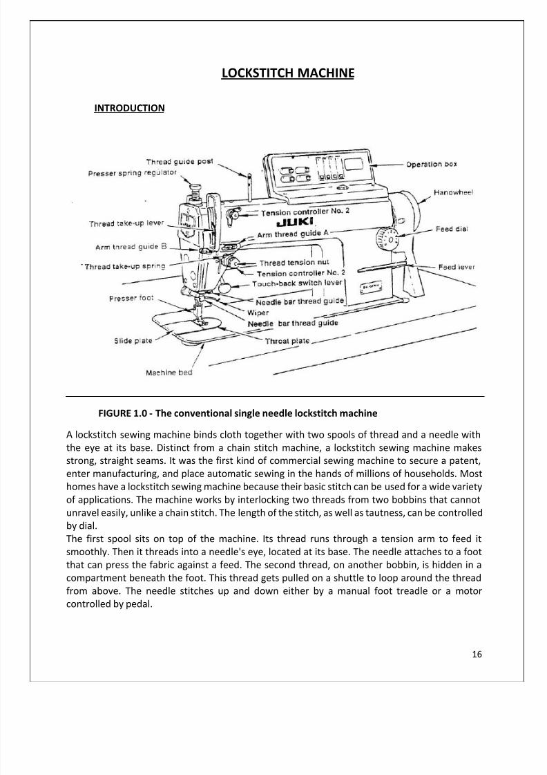
FIGURE 1.0 - The conventional single needle lockstitch machine
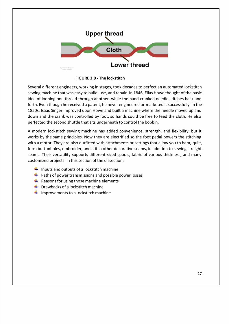
A lockstitch sewing machine binds cloth together with two spools of thread and a needle with
the eye at its base. Distinct from a chain stitch machine, a lockstitch sewing machine makes
strong, straight seams. It was the first kind of commercial sewing machine to secure a patent,
enter manufacturing, and place automatic sewing in the hands of millions of households. Most
homes have a lockstitch sewing machine because their basic stitch can be used for a wide variety
of applications. The machine works by interlocking two threads from two bobbins that cannot
unravel easily, unlike a chain stitch. The length of the stitch, as well as tautness, can be controlled
by dial.
The first spool sits on top of the machine. Its thread runs through a tension arm to feed itsmoothly. Then it threads into a needle's eye, located at its base. The needle attaches to a foot
that can press the fabric against a feed. The second thread, on another bobbin, is hidden in a
compartment beneath the foot. This thread gets pulled on a shuttle to loop around the thread
from above. The needle stitches up and down either by a manual foot treadle or a motor
controlled by pedal.
8/9/2019 Machine Elements Assignment
http://slidepdf.com/reader/full/machine-elements-assignment 17/22
17
FIGURE 2.0 - The lockstitch
Several different engineers, working in stages, took decades to perfect an automated lockstitch
sewing machine that was easy to build, use, and repair. In 1846, Elias Howe thought of the basic
idea of looping one thread through another, while the hand-cranked needle stitches back and
forth. Even though he received a patent, he never engineered or marketed it successfully. In the
1850s, Isaac Singer improved upon Howe and built a machine where the needle moved up and
down and the crank was controlled by foot, so hands could be free to feed the cloth. He also
perfected the second shuttle that sits underneath to control the bobbin.
A modern lockstitch sewing machine has added convenience, strength, and flexibility, but it
works by the same principles. Now they are electrified so the foot pedal powers the stitching
with a motor. They are also outfitted with attachments or settings that allow you to hem, quilt,
form buttonholes, embroider, and stitch other decorative seams, in addition to sewing straight
seams. Their versatility supports different sized spools, fabric of various thickness, and many
customized projects. In this section of the dissection;
Inputs and outputs of a lockstitch machinePaths of power transmissions and possible power losses
Reasons for using those machine elements
Drawbacks of a lockstitch machine
Improvements to a lockstitch machine
8/9/2019 Machine Elements Assignment
http://slidepdf.com/reader/full/machine-elements-assignment 18/22
18
INPUTS AND OUTPUTS, PATHS OF POWER TRANSMISSION AND POSSIBLE POWER
LOSSES IN A LOCKSTITCH MACHINE
INPUTS AND OUTPUTS
The main input of the machine, is an electrical motor which then transmits power and drivingforce to the system and the final output is the reciprocatory vertical movement of the needle and
the rotational motion of the bobbin.
PATHS OF POWER TRANSMISSION
The electric motor is connected to a drive wheel via a drive belt. The drive wheel rotates the
length of the top drive which is connected to several different machine elements shaft. The end
of a crank shaft rotates, it drives the needle bar up and down. The thread tensioner arm crank
also moves. Move in synchronization with the needle bar clamp arm reduced to create enough
slack to form a loop in the fabric, and then stops to tighten the loop after it is released from the
shuttle hook.
The wire extends from a reel on the top of the machine, through the clamping arm and via a
tension disc assembly. By rotating the entire disk, the drain can tighten the yarn feed to the
needle. The voltage should be stricter when the thinner and more flexible fabric sewn heavier
fabric while sewing.
The first element along the stem is a single belt which rotates a lower drive shaft. The lower end
of the drive shaft is connected to a bevel gear set which rotates the shuttle assembly. Since the
two are connected to the same shaft, the shuttle assembly and the needle assembly is always
move in unison.
Ties of lower driving operating the feed mechanism shaft is moved. A drop feed slide forward link
and backward at every cycle. Simultaneously, the other link conveyor moves up and down. The
two rods are synchronized such that the drive pressed against the fabric, which moves forward
claw, and then moves downwardly to release the tissue. The conveyor moves rearwardly before
pressing the fabric to repeat the cycle.
The motor is controlled by a pedal, which allows for easily varying the speed of drains. The good
thing about this design is that everything is connected, so that when the pedal is depressed, the
motor accelerates all processes at the same pace. The process is always perfectly synchronized,
regardless of the rotational speed of the engine.

8/9/2019 Machine Elements Assignment
http://slidepdf.com/reader/full/machine-elements-assignment 19/22
19
REASONS FOR USING THE SPECIFIC MACHINE ELEMENTS
Timing belt to transmit power from the motor
There’s a timing belt connecting the motor to the drive wheel. The timing belt has
been used here due to the unique options it provides than other types of belts,
mainly since there’s no slippage due to the teeth like structure. This is quite
important because to produce the stitch, the motion of the needle and the bobbin
should be in synchronization. Any slippage could interrupt this synchronization
and then the loop will not be produced. Hence it is important to use a timing belt
specifically here.
Bevel gears
From the main drive wheel which is driven by the motor through a timing belt,
power needs to be transmitted to both the motion of the bobbin and the
reciprocatory vertical motion of the needle. A bevel gear system is hence used to
transmit power from the main shaft to the lower segments of the machine.Spur gears
In some parts of the machine, spur gears have been used over belt drives since
they provide motion with constant speeds without any slippage. And also usage
of gears is more economical if the elements are properly lubricated and
maintained. It is important to use gearing since otherwise, the synchronized
motion of the needle and the bobbin may be interrupted.
Cam mechanism
A cam is connected to the main shaft in order to control the speed of the vertical
reciprocatory motion of the needle. The speed of the needle when going down
and coming up are different. This is important because of the same reasonmentioned in above sections, the synchronized motion of the bobbin and the
needle.
8/9/2019 Machine Elements Assignment
http://slidepdf.com/reader/full/machine-elements-assignment 20/22
20
POSSIBLE POWER LOSSES
A significant amount of power is lost also in the lockstitch machine as in any mechanical system,
mainly in mechanical forms. There is a number of numerous ways in which power is lost;
As sound
As heat
Mechanical vibrations produced
Due to the constant operation of the electric motor, since it generates a considerable noise,
power is lost as sound from the system.
As in any mechanical system, friction is an incident that cannot be eliminated. So there’s always
power loss due to friction mainly in the form of heat. But friction is also used in this machine to
produce the lockstitch.
And also the constant operation of the motor generates mechanical vibrations unnecessarily.
This is also a power loss to the environment from the system.

8/9/2019 Machine Elements Assignment
http://slidepdf.com/reader/full/machine-elements-assignment 21/22
21
DRAW BACKS AND IMPROVEMENTS OF A LOCKSTITCH MACHINE
DRAWBACKS
High energy consumption due to the constant operation of the electric motor which is
the driving force of the machine.
Oil stains might fall on the fabric, and might not be cleaned
Noisy operation due to the electric motor.
Unnecessary mechanical vibrations generated.
Belt dive might wear out with time due to constant operation since these machines are
used for long periods of time per day and also heat is also generated due to mechanical
power losses.
IMPROVEMENTS
Energy saving techniques
The latest compact-size servomotor has been adopted.
The modern day lockstitch machines adopted the latest compact-size servomotor as its driving
source. This latest compact-size servomotor is an energy-saving, highly efficient motor which is
able to run under a high torque and has a broader range of speed. In addition, the servomotor is
installed with a direct-drive system to transmit the motor power directly to the sewing machine,
thereby achieving improved power-consumption saving, quicker response, quicker startup,
increased accuracy of the stop position and stronger material penetrating force of the needle.
The new model control box, which energy-saving mode is provided.
The new models of lockstitch machines which consist of an energy-saving mode, has beendeveloped. This control box is the first one which provides an energy-saving mode for the sewing
machine. The power consumption during standby, when the motor is at rest, is reduced by
approximately 20%. In addition, abundantly incorporated state-of-the-art energy-saving features
such as a compact-in-size solenoid for the auto-lifter allow the machines to reduce power
consumption, to increase productivity and to be friendly to the environment.
Dry technology – Oil stains on the material being sewn are reduced, thereby improving
product quality
The advanced dry technology helps prevent oil stains on the material being sewn. The mainsource of oil stains is the frame. The semi-dry head type sewing machine comes with a frame
which does not need lubrication. The fully-dry head type sewing machine is an even further
evolved dry-head type which comes with a frame and a hook section which do not need
lubrication.
8/9/2019 Machine Elements Assignment
http://slidepdf.com/reader/full/machine-elements-assignment 22/22
22
Design for achieving silent operation – The operating noise by the machine is reduced,
helping reduce operator fatigue
One of the eternal challenges of a sewing plant is the improvement of the work environment.
One of the factors to be improved is noise within the plant. The DDL-9000B 1-needle lockstitch
machine is the sewing machine which is used most frequently in the sewing plant. For this reason,the noise generating mechanisms have been attuned to eliminate any harsh noise.
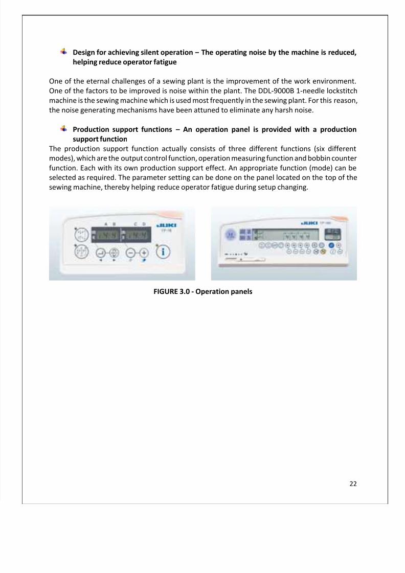
Production support functions – An operation panel is provided with a production
support function
The production support function actually consists of three different functions (six different
modes), which are the output control function, operation measuring function and bobbin counter
function. Each with its own production support effect. An appropriate function (mode) can be
selected as required. The parameter setting can be done on the panel located on the top of the
sewing machine, thereby helping reduce operator fatigue during setup changing.
FIGURE 3.0 - Operation panels