Embed Size (px)
Citation preview

– 1 –
This manual contains information on setting configurations (initial and maintenance settings). Please read the manual thoroughly, and make the settings accordingly. Refer to the Installation Manual of this remote controller for how to install the remote controller, and refer to the Installation Manual of the air conditioning units for how to install them and how to connect the remote controller wiring. After reading this manual, pass the manual on to the end user to retain for future reference.
1. Remote controller button functions
Button operations on the Main menu
WT06011X01
CITY MULTI Control System
MA Remote Controller PAR-30MAAUInitial Setting Manual
For distribution to dealers and contractors
RETURN SELECTMENU HOLDON
OFF
(8) Backlit LCD
(2) Function buttons F1, F2, F3, and F4 from the left(7) Operation indicator(1) ON/OFF button
(4) RETURN button(3) MENU button
(5) SELECT button
(6) HOLD button
(1) ON/OFF buttonUse to turn ON/OFF the indoor unit.
(2) Function buttonsUse to select the operation mode or to set the temperature and fan speed on the Main display. Use to select items on other screens.
(3) MENU buttonUse to bring up the Main menu.
(4) RETURN buttonUse to return to the previous screen.
(5) SELECT buttonUse to jump to the setting screen or to save the settings.
(6) HOLD buttonUse to turn On/Off the hold function.
(7) Operation indicatorStays lit during normal operation. Blinks during startup and when an error occurs.
(8) Backlit LCDDot display. When the backlight is off, pressing any button turns the backlight on and it will stay lit for a certain period of time depending on the screen. Performing any button operation keeps the backlight on.
Note: When the backlight is off, pressing any button turns the backlight on and does not perform its function. (except for the ON/OFF and HOLD buttons)
CursorMove the cursor to the desired function with the F1 and F2 buttons, and press the SELECT button to go to the next page. Password may be required.
The function of the MENU, SELECT, and RETURN buttons will appear on the setting screens.
Button function guide will appear at the bottom of the screens.
F1 F2 F3 F4
Main
Main display: RETURNCursor Page
Main menuVane·Louver·Vent. (Lossnay)High powerTimerWeekly timerOU silent mode
Page
Pressing the MENU button will bring up the Main menu as shown below. (Refer to section 2.(2) "Main display" for details.)
1/3 Vane·Louver·Vent. (Lossnay)High powerTimerWeekly timerOU silent mode
2/3 RestrictionEnergy savingFilter informationError informationMaintenance
3/3 Initial settingService
*1 Refer to the Instructions Book for details.*2 Explained in this manual.*3 If no buttons are pressed for 10 minutes on the initial
setting screens, or 2 hours on the service screens (10 minutes on some screens), the screen will automatically return to the Main display. Any settings that have not been saved will be lost.
The available items on the menu depend on the connected indoor unit model. For items not described in the manuals that are enclosed with the MA remote controller, refer to the manuals that came with the air conditioning units.
*1*1*1*1*1
*1*1*1*1*1
*2 *3*2 *3
– 2 –
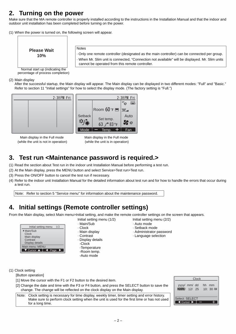
2. Turning on the powerMake sure that the MA remote controller is properly installed according to the instructions in the Installation Manual and that the indoor and outdoor unit installation has been completed before turning on the power.
(1) When the power is turned on, the following screen will appear.
(2) Main displayAfter the successful startup, the Main display will appear. The Main display can be displayed in two different modes: "Full" and "Basic." Refer to section 11 "Initial settings" for how to select the display mode. (The factory setting is "Full.")
3. Test run <Maintenance password is required.>(1) Read the section about Test run in the indoor unit Installation Manual before performing a test run.(2) At the Main display, press the MENU button and select Service>Test run>Test run.(3) Press the ON/OFF button to cancel the test run if necessary.(4) Refer to the indoor unit Installation Manual for the detailed information about test run and for how to handle the errors that occur during
a test run.
4. Initial settings (Remote controller settings)From the Main display, select Main menu>Initial setting, and make the remote controller settings on the screen that appears.
(1) Clock setting
Notes· Only one remote controller (designated as the main controller) can be connected per group.· When Mr. Slim unit is connected, “Connection not available” will be displayed. Mr. Slim units
cannot be operated from this remote controller.Normal start up (indicating the
percentage of process completion)
Main display in the Full mode (while the unit is not in operation)
Main display in the Full mode (while the unit is in operation)
Note: Refer to section 5 "Service menu" for information about the maintenance password.
Initial setting menu (1/2)· Main/Sub· Clock· Main display· Contrast· Display details -Clock -Temperature -Room temp. -Auto mode
Initial setting menu (2/2)· Auto mode· Setback mode· Administrator password· Language selection
[Button operation][1] Move the cursor with the F1 or F2 button to the desired item.[2] Change the date and time with the F3 or F4 button, and press the SELECT button to save the
change. The change will be reflected on the clock display on the Main display.Note: Clock setting is necessary for time display, weekly timer, timer setting and error history.
Make sure to perform clock setting when the unit is used for the first time or has not used for a long time.
Please Wait10%
Fri Fri
RoomAuto
Set temp.
Mode Temp. Fan
Setback
Initial setting menu
Main menu: MENUCursor Page
Main/SubClockMain displayContrastDisplay details
Clock
Select: SELECTCursor
2010/ 12/ 25 10: 30yyyy/ mm/ dd hh mm
– 3 –
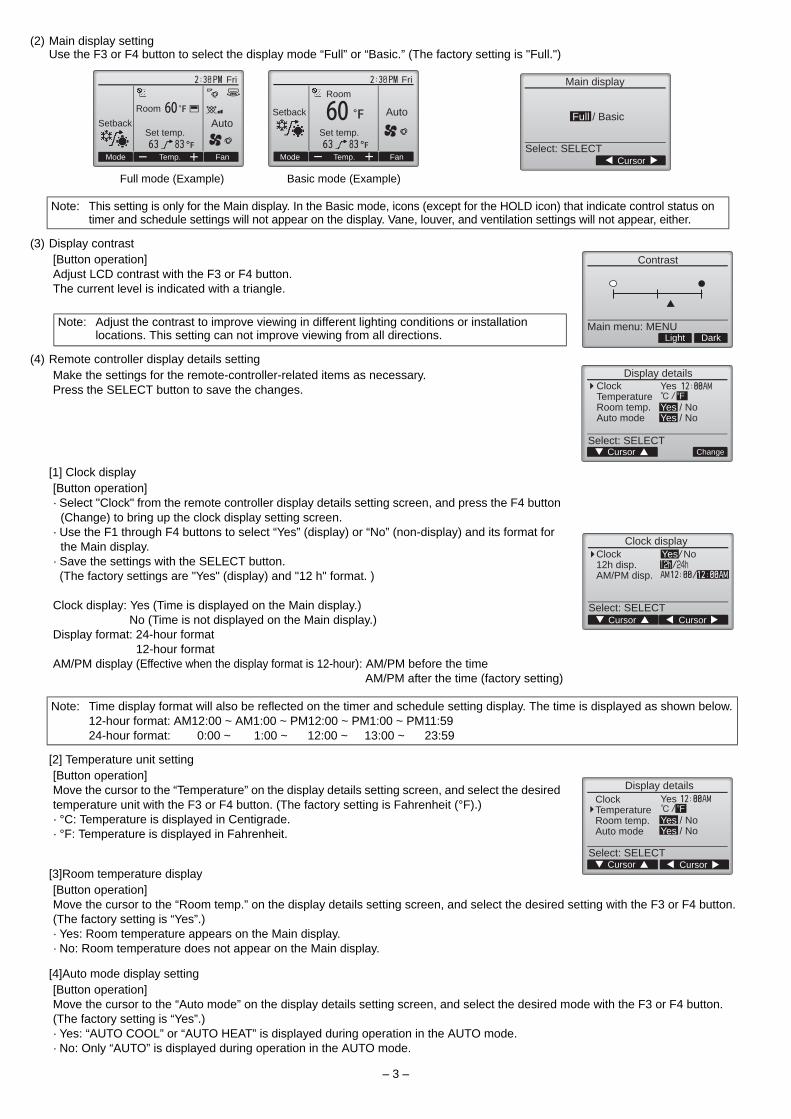
(2) Main display settingUse the F3 or F4 button to select the display mode “Full” or “Basic.” (The factory setting is "Full.")
(3) Display contrast
(4) Remote controller display details setting
[1] Clock display
[2] Temperature unit setting
[3]Room temperature display
[4]Auto mode display setting
Full mode (Example) Basic mode (Example)
Note: This setting is only for the Main display. In the Basic mode, icons (except for the HOLD icon) that indicate control status on timer and schedule settings will not appear on the display. Vane, louver, and ventilation settings will not appear, either.
[Button operation]Adjust LCD contrast with the F3 or F4 button.The current level is indicated with a triangle.
Note: Adjust the contrast to improve viewing in different lighting conditions or installation locations. This setting can not improve viewing from all directions.
Make the settings for the remote-controller-related items as necessary.Press the SELECT button to save the changes.
[Button operation]· Select "Clock" from the remote controller display details setting screen, and press the F4 button
(Change) to bring up the clock display setting screen. · Use the F1 through F4 buttons to select “Yes” (display) or “No” (non-display) and its format for
the Main display.· Save the settings with the SELECT button. (The factory settings are "Yes" (display) and "12 h" format. )
Clock display: Yes (Time is displayed on the Main display.) No (Time is not displayed on the Main display.)Display format: 24-hour format 12-hour formatAM/PM display (Effective when the display format is 12-hour): AM/PM before the time AM/PM after the time (factory setting)
Note: Time display format will also be reflected on the timer and schedule setting display. The time is displayed as shown below.12-hour format: AM12:00 ~ AM1:00 ~ PM12:00 ~ PM1:00 ~ PM11:5924-hour format: 0:00 ~ 1:00 ~ 12:00 ~ 13:00 ~ 23:59
[Button operation]Move the cursor to the “Temperature” on the display details setting screen, and select the desired temperature unit with the F3 or F4 button. (The factory setting is Fahrenheit (°F).)· °C: Temperature is displayed in Centigrade.· °F: Temperature is displayed in Fahrenheit.
[Button operation]Move the cursor to the “Room temp.” on the display details setting screen, and select the desired setting with the F3 or F4 button. (The factory setting is “Yes”.)· Yes: Room temperature appears on the Main display.· No: Room temperature does not appear on the Main display.
[Button operation]Move the cursor to the “Auto mode” on the display details setting screen, and select the desired mode with the F3 or F4 button.(The factory setting is “Yes”.)· Yes: “AUTO COOL” or “AUTO HEAT” is displayed during operation in the AUTO mode. · No: Only “AUTO” is displayed during operation in the AUTO mode.
Set temp. Set temp.
Fri Fri
Mode Temp. Fan Mode Temp. Fan
Room AutoSetback
SetbackAuto
Room
Full / Basic
Main display
CursorSelect: SELECT
DarkLight
Contrast
Main menu: MENU
Display details
Cursor ChangeSelect: SELECT
ClockTemperatureRoom temp.Auto mode
Yes
Yes / NoYes / No
Clock display
Cursor CursorSelect: SELECT
Clock12h disp.AM/PM disp.
Yes No
Display details
CursorCursorSelect: SELECT
ClockTemperatureRoom temp.Auto mode
Yes
Yes / NoYes / No

– 4 –
(5) Auto mode setting
(6) Setback mode setting
(7) Administrator password setting
(8) Language selection
[Button operation]Whether or not to use the AUTO mode can be selected by using the F3 or F4 button. This setting is valid only when indoor units with the AUTO mode function are connected.(The factory setting is “Yes”.)Press the SELECT button to save the changes made.· Yes: The AUTO mode can be selected in the operation mode setting.· No: The AUTO mode cannot be selected in the operation mode setting.
[Button operation]If setback mode setting can be made on multiple units, make the setting on one of the units only. The Setback mode can be selected by using the F3 or F4 button. (The factory setting is “Yes”.)Press the SELECT button to save the changes made.· Yes: The Setback mode can be selected in the operation mode setting.· No: The Setback mode cannot be selected in the operation mode setting.
Note: The setback mode can be set from this remote controller only in the systems that have the following type of units: · Unit that features simultaneous cooling and heating functions: PURY/PQRY series· Unit that features simultaneous cooling and heating functions with the use of external
heaters (Field supply): PUHY series with external heater(Depending on the production month, the simultaneous cooling and heating function is limited on some PUHY units. For the availability of this function, contact a local sales representative.)Type of units other than the types above cannot be operated in the setback mode. Set “No” in this case.
[Button operation][1] To enter the current Administrator password (4 numerical digits), move the cursor to the digit
you want to change with the F1 or F2 button, and set each number (0 through 9) with the F3 or F4 button.
[2] Press the SELECT button.
Note: The initial administrator password is "0000." Change the default password as necessary to prevent unauthorized access. Have the password available for those who need it.
Note: If you forget your administrator password, you can initialize the password to the default password "0000" by pressing and holding the F1 and F2 buttons simultaneously for three seconds on the administrator password setting screen.
[3] If the password matches, a window to enter a new password will appear. Enter a new password in the same way as explained above, and press the SELECT button.
[4] Press the F4 button (OK) on the password change confirmation screen to save the change. Press the F3 button (Cancel) to cancel the change.
Note: The administrator password is required to make the settings for the following items.· Timer setting · Weekly timer setting · Energy-save setting· Outdoor unit silent mode setting · Restriction settingRefer to the Instruction Book that came with the remote controller for the detailed information about how to make the settings for these items.
[Button operation]Move the cursor to the language you desire with the F1 through F4 buttons.Press the SELECT button to save the setting. (The factory setting is “English.”)
Auto mode
Auto mode Yes / No
Select: SELECTCursor
Setback mode
Setback mode Yes / No
Select: SELECTCursor
Administrator password
Enter administrator password
Select: SELECTCursor
Administrator password
Enter administrator password
Change administrator password.
Select: SELECTCursor
Administrator password
Enter administrator password
Update administrator password?
Cancel OK
CursorSelect: SELECT
FrançaisLanguage selection
Cursor
EnglishEspañol

– 5 –
5. Service menu (Maintenance password is required.)At the Main display, press the MENU button and select “Service” to make the maintenance settings.
When the Service menu is selected, a window will appear asking for the password.To enter the current maintenance password (4 numerical digits), move the cursor to the digit you want to change with the F1 or F2 button, and set each number (0 through 9) with the F3 or F4 button. Then, press the SELECT button.
If the password matches, the Service menu will appear.
(1) Test run
(2) Input maintenance Info.
(3) LOSSNAY settingThis setting is required only when the operation of City Multi units is interlocked with LOSSNAY units. Interlock settings can be made for the indoor unit to which the remote controller is connected. (They can also be confirmed or deleted.)
Note: The initial maintenance password is "9999." Change the default password as necessary to prevent unauthorized access. Have the password available for those who need it.
Note: If you forget your maintenance password, you can initialize the password to the default password "9999" by pressing and holding the F1 and F2 buttons simultaneously for three seconds on the maintenance password setting screen.
Note: Air conditioning units may need to be stopped to make certain settings. There may be some settings that cannot be made when the system is centrally controlled.
Select "Test run" from the Service menu to bring up the Test run menu.· Test run: Select this option to perform a test run.· Drain pump test run: Select this option to perform a test run on the drain pump on the indoor unit. Applicable only to the type of indoor units that support the test run function.
Note: Refer to the indoor unit Installation Manual for the detailed information about test run.
Select "Input maintenance Info." from the Service menu to bring up the Maintenance information screen. Refer to the indoor unit Installation Manual for how to make the settings.Note: The following settings can be made from the Maintenance Information screen.
•Registering model names and serial numbersEnter the model names and serial numbers of outdoor and indoor units. The information entered will appear on the Error information screen. Model names can have up to 18 characters, and the serial numbers can have up to 8 characters.
•Registering dealer informationEnter phone number of a dealer. The entered information will appear on the Error information screen. Phone number can have up to 13 characters.
•Initializing maintenance informationSelect the desired item to initialize the above settings.
Note: • Use the centralized controller to make the settings if it is connected.• To interlock the operation of the indoor units with the LOSSNAY units, be sure to interlock the addresses of ALL indoor
units in the group and that of the LOSSNAY unit.
[Button operation][1] When “Lossnay” on the Service
menu is selected, the remote controller will automatically begin searching for the registered LOSSNAY addresses of the currently connected indoor unit.
[2] When the search is completed, the smallest address of the indoor units that are connected to the remote controller and the address of the interlocked LOSSNAY unit will appear. "--" will appear if no LOSSNAY unit is interlocked with the indoor units.
If no settings need to be made, press the RETURN button to go back to the Service menu.
Service menu
CursorSelect: SELECT
Enter maintenance password
Service menu Service menu
Cursor CursorMain menu: RETURN Main menu: RETURN
Test runInput maintenance info.LossnayCheckSelf check
Maintenance passwordRemote controller check
Service menu Service menu
Service menu: RETURN Service menu: RETURN
Not available.Please stop the unit.
Not available.Centrally controlled.
Test run menu
CursorService menu: MENU
Test runDrain pump test run
Maintenance information
CursorService menu: MENU
Model name inputSerial No. inputDealer information inputInitialize maintenance info.
LossnayIU addressLossnay address
Collecting data
Lossnay
Cursor AddressSelect: SELECT
IU addressLossnay addressFunction Set/Conf/Del.

– 6 –
(4) Check
(5) Diagnostic function.
To make LOSSNAY interlock setting
[3] Enter the addresses of the indoor unit and the LOSSNAY unit to be interlocked, with the F1 through F4 buttons, select "Set" in the "Function”, and press the SELECT button to save the settings. "Sending data" will appear on the screen. If the setting is successfully completed, "Setting completed" will appear.
To search for the LOSSNAY address
[4] Enter the address of the indoor unit to which the remote controller is connected, select "Conf" in the "Function", and press the SELECT button. "Collecting data" will appear on the screen. If the signal is received correctly, the indoor unit address and LOSSNAY address will appear. "--" will appear when no LOSSNAY unit is found. “Unit not exist” will appear if no indoor units that are correspond to the entered address are found.
To delete the interlock setting
[5] To delete the interlocked setting between LOSSNAY unit and the indoor units to which the remote controller is connected, enter the indoor unit address and LOSSNAY address with the F1 through F4 buttons, select "Del." in the "Function", and press the SELECT button. "Deleting" will appear. The screen will return to the search result screen if the deletion is successfully completed. “Unit not exist” will appear if no indoor units that are correspond to the entered address are found. If deletion fails, "Request rejected" will appear on the screen.
Select "Check" on the Service menu to bring up the Check menu screen.
[1] Error history Select “Error history” from the Check menu, and
press the SELECT button to view up to 16 error history records. Four records are shown per page, and the top record on the first page indicates the latest error record.
"Error history deleted" will appear on the screen. Press the RETURN button to go back to the Check menu screen.
[Deleting the error history]To delete the error history, press the F4 button (Delete) on the screen that shows error history. A confirmation screen will appear asking if you want to delete the error history.Press the F4 button (OK) to delete the history.
Error history of each unit can be checked via the remote controller.[Procedures][1] Select "Self check" from the Service menu, and press the SELECT button to
view the Self check screen.[2] With the F1 or F2 button, enter M-NET address, and press the SELECT button.[3] Error code, unit number, attribute, and indoor unit demand signal ON/OFF
status at the contact will appear. "-" will appear if no error history is available.
When there is no error history
LossnayLossnay
Return: RETURN
IU addressLossnay address
IU addressLossnay address
Sending data Setting completed
LossnayLossnay
Return: RETURN
IU addressLossnay address
IU addressLossnay address
Collecting data Unit not exist
LossnayLossnay
Return: RETURN
IU addressLossnay address
IU addressLossnay address
Deleting Request rejected
Check menu
CursorService menu: MENU
Error history
Error history
Page DeleteCheck menu: RETURN
Error Unt# mm/dd/yyError history
Check menu: RETURN
Error history deleted
Error history
Cancel OK
Delete error history?
Self check
Select: SELECT
M-NET address
Address
Self check
Contact
Return: RETURNReset
M-NET address
Error Grp.IC
Self check
Contact
Return: RETURNReset
M-NET address
Error Grp.---- ---

– 7 –
(6) Setting the maintenance passwordTake the following steps to change the maintenance password.
6. Remote controller checkWhen the remote controller does not work properly, use the remote controller checking function to troubleshoot the problem.(1) Check the remote controller display and see if anything is displayed (including lines). Nothing will appear on the remote controller
display if the correct voltage (8.5-12 VDC) is not supplied to the remote controller. If this is the case, check the remote controller wiring and indoor units.[Procedures][1] Select “Remote controller check” from the Service menu, and press the SELECT button to start the remote controller check and see
the check results. To cancel the remote controller check and exit the Remote controller check menu screen, press the MENU or the RETURN button. The remote controller will not reboot itself.
OK: No problems are found with the remote controller. Check other parts for problems.6832: There is noise on the transmission line, or the indoor unit or another remote controller is faulty. Check the transmission line and the
other remote controllers.NG (ALL0, ALL1): Send-receive circuit fault. Remote controller needs replacing.ERC: The number of data errors is the discrepancy between the number of bits in the data transmitted from the remote controller and that of the data that was actually transmitted over the transmission line. If data errors are found, check the transmission line for external noise interference.
[2] If the SELECT button is pressed after the remote controller check results are displayed, remote controller check will end, and the remote controller will automatically reboot itself.
[Resetting the error history][1] Press the F4 button (Reset) on
the screen that shows the error history. A confirmation screen will appear asking if you want to delete the error history.
[2] Press the F4 button (OK) to delete the error history. If deletion fails, "Request rejected” will appear, and "Unit not exist" will appear if no indoor units that are correspond to the entered address are found.
[Procedures][1] Select "Maintenance password" on the Service menu, and press the SELECT button to bring up
the screen to enter a new password.[2] Move the cursor to the digit you want to change with the F1 or F2 button, and set each digit to the
desired number (0 through 9) with the F3 or F4 button.[3] Press the SELECT button to save the new password.[4] A confirmation screen will appear asking if you want to change the maintenance password. Press
the F4 button (OK) to save the change. Press the F3 button (Cancel) to cancel the change.
[5] “Changes saved” will appear when the password is updated.[6] Press the MENU button to return to the Service menu or press the RETURN button to go back to
the "Maintenance password” screen.
Select “Remote controller check”. Remote controller check results screen
Self check
Delete error history?
M-NET address
Cancel OK
Self check
Return: RETURN
M-NET address
Error history deleted
Maintenance password
CursorSelect: SELECT
Enter maintenance password
Change maintenance password.
Maintenance password
Cancel OK
Enter maintenance password
Update maintenance password?
Maintenance password
Service menu: MENU
Enter maintenance password
Changes saved
Service menu Remote controller check Remote controller check
CursorMain menu: RETURN Begin: SELECT Exit: SELECT
Maintenance passwordRemote controller check
Start checking?

– 8 –
HEAD OFFICE: TOKYO BLDG., 2-7-3, MARUNOUCHI, CHIYODA-KU, TOKYO 100-8310, JAPAN