Embed Size (px)
Citation preview
APPLICATION NOTE
S3F80KB IR REMOTE CONTROLLER
October 2008
REV 0.00
Confidential Proprietary of Samsung Electronics Co., Ltd Copyright © 2008 Samsung Electronics, Inc. All Rights Reserved
S3F80KB_AN_REV 0.00 (Preliminary Spec) IR REMOTE CONTROLLER
1
Trademark & Copyright Information
Copyright © 2008 Samsung Electronics Co., Ltd. All Rights Reserved.
The information in this publication has been carefully checked and is believed to be entirely accurate at the time of publication. Samsung assumes no responsibility for possible errors or omissions, or for any consequences resulting from the use of the information contained herein.
No part of the information contained in this document maybe reproduced or used without the prior consent of Samsung Electronics Co., Ltd.
Samsung reserves the right to make any changes in its products or product specifications including documentation with the intent to improve function or design at any time without notice.
Samsung makes no warranty, representation, or guarantee regarding the suitability of its products for any particular purpose, nor does Samsung assume any liability arising out of the application or use of any product or circuit and specifically disclaims any and all liability, including without limitation any consequential or incidental damages.
SAMSUNG ELECTRONICS CO., LTD. SAN #24 NONGSEO-DONG, GIHEUNG-GU, Yongin-City, Gyeonggi-Do, Korea 446-711
TEL : (82)-(31)-209-6575 FAX : (82)-(31)-209-1973
IR REMOTE CONTROLLER S3F80KB_AN_REV 0.00 (Preliminary Spec)
2
Table of Contents
1 Overview................................................................................................................................................. 4
1.1 S3F80KBX Microcontroller................................................................................................................. 4
1.2 IR Signal ............................................................................................................................................. 5
2 Hardware Implementation......................................................................................................................... 6
2.1 IR Remote Controller Schematic........................................................................................................ 6
2.2 Application Features........................................................................................................................... 6
2.3 Pin Assignments................................................................................................................................. 7
2.4 Used Block ......................................................................................................................................... 7
2.5 Transmission Mode............................................................................................................................ 8
2.5.1 Counter A.................................................................................................................................... 8
2.5.2 Timer 1 ........................................................................................................................................ 8
2.5.3 Port.............................................................................................................................................. 9
2.6 Reception Mode ................................................................................................................................. 9
2.6.1 Timer 1 ........................................................................................................................................ 9
2.6.2 Timer 0 ........................................................................................................................................ 9
3 Software Implementation .......................................................................................................................... 10
3.1 Transmission Module ......................................................................................................................... 11
3.1.1 IR Transmission Description....................................................................................................... 11
3.1.2 Bit Transmission ......................................................................................................................... 11
3.2 8-Bit Transmission.............................................................................................................................. 14
3.2.1 8-Bit Data Transmission Module................................................................................................. 15
3.3 Frame Transmission........................................................................................................................... 16
3.3.1 Frame Transmission Module ...................................................................................................... 16
3.4 IR Reception Module.......................................................................................................................... 18
3.4.1 IR Reception Description ............................................................................................................ 18
3.5 Leader Reception ............................................................................................................................... 19
3.6 Data Bit Reception ............................................................................................................................. 23
4 Test Method............................................................................................................................................... 27
4.1 IR Test Method................................................................................................................................... 27
4.2 IR Test Flow ....................................................................................................................................... 28
S3F80KB_AN_REV 0.00 (Preliminary Spec) IR REMOTE CONTROLLER
3
List of Figures
Figure Title Page Number Number
1. IR Signal ....................................................................................................................................... 5 2. IR Remote Controller Schematic (44-Pin).................................................................................... 6 3. Carrier Frequency ........................................................................................................................ 8 4. Timer1 IR Transmission ............................................................................................................... 9 5. Bit Transmission Flow .................................................................................................................. 11 6. 8-Bit Transmission Flow............................................................................................................... 14 7. Frame Transmission Flow............................................................................................................ 16 8. Leader Reception Flow ................................................................................................................ 19 9. Bit Reception Flow ....................................................................................................................... 23 10. Application Concept Diagram....................................................................................................... 27 11. IR Test Flow ................................................................................................................................. 28 12. IR Remote Controller Test Board................................................................................................. 29
List of Tables
Table Title Page Number Number
1. Pin Configuration.......................................................................................................................... 7 2. Block Description.......................................................................................................................... 7 3. Used Libraries .............................................................................................................................. 10
IR REMOTE CONTROLLER S3F80KB_AN_REV 0.00 (Preliminary Spec)
4
IR REMOTE CONTROLLER
1 OVERVIEW
The IR remote controller application note is designed for application designers and programmers who are using S3F80KBX microcontroller for IR remote controller application development.
This application note describes the learning remote controller of two types universal remote controller. One of the universal remote controller is learning remote controller and another one is a lookup table remote controller. Both types have their own advantages. Look up table remote controller have a previously stored lookup table codes. On the other hand learning remote controller doesn’t have it, but it can learn new codes from other remote controllers. So learning remote controller have to implement a transmission mode and reception mode. This application note describes both modes.
Application Note contents
• Application Note document
• Source code (included OpenICE-i2000 project file)
• Board schematic
1.1 S3F80KBX MICROCONTROLLER
The S3F80KBX single-chip CMOS microcontroller is fabricated using a highly advanced CMOS process and is based on Samsung's newest CPU architecture.
The S3F80KBX is the microcontroller which has 60-Kbyte Flash Memory ROM.
Using a proven modular design approach, Samsung engineers developed S3F80KBX by integrating the following peripheral modules with the powerful SAM8 RC core:
• Internal LVD circuit and 16-bit-programmable pins for external interrupts.
• One 8-bit basic timer for oscillation stabilization and watchdog function (system reset).
• One 8-bit Timer/counter with three operating modes.
• Two 16-bit timer/counters with selectable operating modes.
• One 8-bit counter with auto-reload function and one-shot or repeat control.
The S3F80KBX is a versatile general-purpose microcontroller, which is especially suitable for use as remote transmitter controller. It is currently available in a 32-pin SOP and 44-pin QFP package.
S3F80KB_AN_REV 0.00 (Preliminary Spec) IR REMOTE CONTROLLER
5
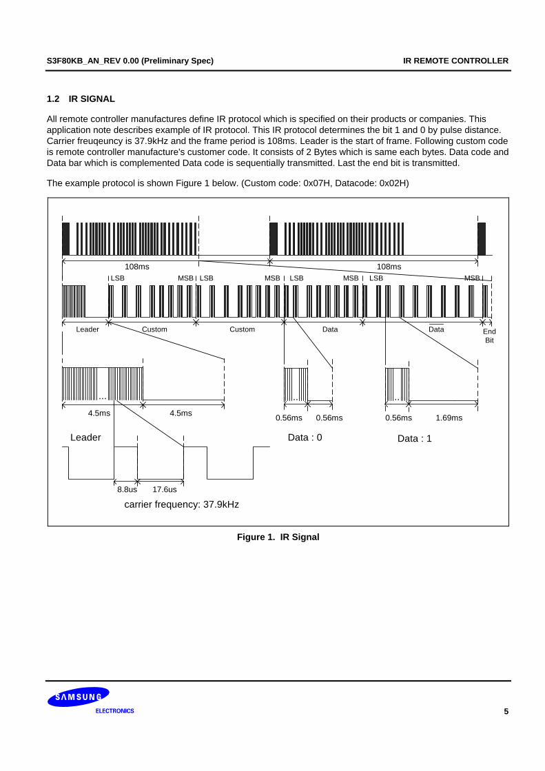
1.2 IR SIGNAL
All remote controller manufactures define IR protocol which is specified on their products or companies. This application note describes example of IR protocol. This IR protocol determines the bit 1 and 0 by pulse distance. Carrier freuqeuncy is 37.9kHz and the frame period is 108ms. Leader is the start of frame. Following custom code is remote controller manufacture's customer code. It consists of 2 Bytes which is same each bytes. Data code and Data bar which is complemented Data code is sequentially transmitted. Last the end bit is transmitted.
The example protocol is shown Figure 1 below. (Custom code: 0x07H, Datacode: 0x02H)
Leader Custom Custom Data Data EndBit
...
4.5ms 4.5ms
.. ..
0.56ms 0.56ms 0.56ms 1.69ms
8.8us 17.6us
carrier frequency: 37.9kHz
Data : 0 Data : 1Leader
108ms 108msLSB MSB LSB MSB LSB MSB LSB MSB
Figure 1. IR Signal
IR REMOTE CONTROLLER S3F80KB_AN_REV 0.00 (Preliminary Spec)
6
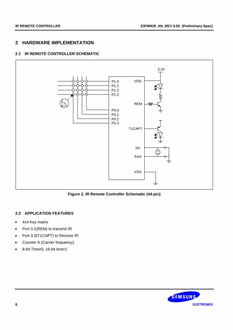
2 HARDWARE IMPLEMENTATION
2.1 IR REMOTE CONTROLLER SCHEMATIC
P1.0P1.1P1.2P1.3
P0.0P0.1P0.2P0.3
REM
Xin
Xout
VDD
VSS
T1CAPT
3.3V
Figure 2. IR Remote Controller Schematic (44-pin)
2.2 APPLICATION FEATURES
• 4x4 Key matrix
• Port 3.1(REM) to transmit IR
• Port 3.3(T1CAPT) to Receive IR
• Counter A (Carrier frequency)
• 8-bit Timer0, 16-bit timer1
S3F80KB_AN_REV 0.00 (Preliminary Spec) IR REMOTE CONTROLLER
7
2.3 PIN ASSIGNMENTS
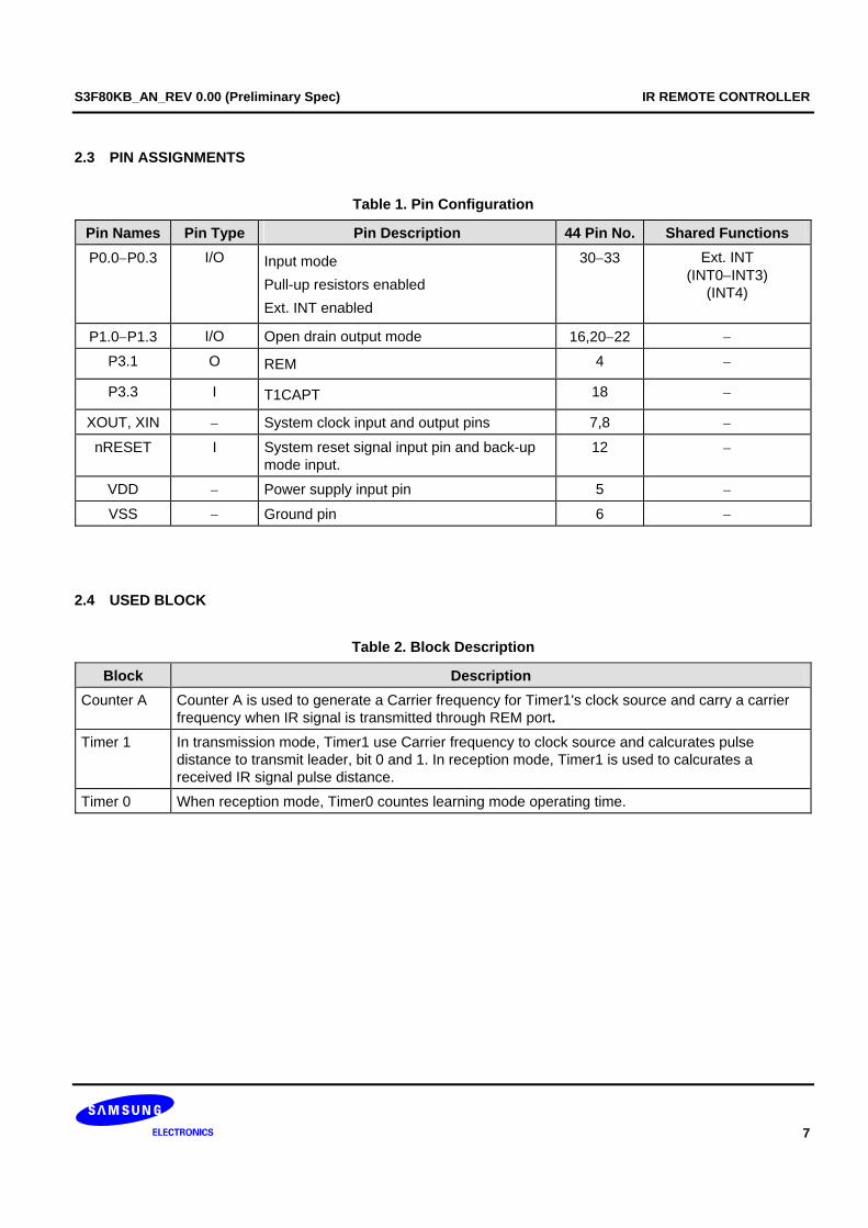
Table 1. Pin Configuration
Pin Names Pin Type Pin Description 44 Pin No. Shared Functions P0.0−P0.3 I/O Input mode
Pull-up resistors enabled Ext. INT enabled
30−33 Ext. INT (INT0−INT3)
(INT4)
P1.0−P1.3 I/O Open drain output mode 16,20−22 −
P3.1 O REM 4 −
P3.3 I T1CAPT 18 −
XOUT, XIN − System clock input and output pins 7,8 −
nRESET I System reset signal input pin and back-up mode input.
12 −
VDD − Power supply input pin 5 −
VSS − Ground pin 6 −
2.4 USED BLOCK
Table 2. Block Description
Block Description Counter A Counter A is used to generate a Carrier frequency for Timer1's clock source and carry a carrier
frequency when IR signal is transmitted through REM port. Timer 1 In transmission mode, Timer1 use Carrier frequency to clock source and calcurates pulse
distance to transmit leader, bit 0 and 1. In reception mode, Timer1 is used to calcurates a received IR signal pulse distance.
Timer 0 When reception mode, Timer0 countes learning mode operating time.
IR REMOTE CONTROLLER S3F80KB_AN_REV 0.00 (Preliminary Spec)
8
2.5 TRANSMISSION MODE
2.5.1 Counter A
26.4us
CDATAL CDATAH
1/3 duty
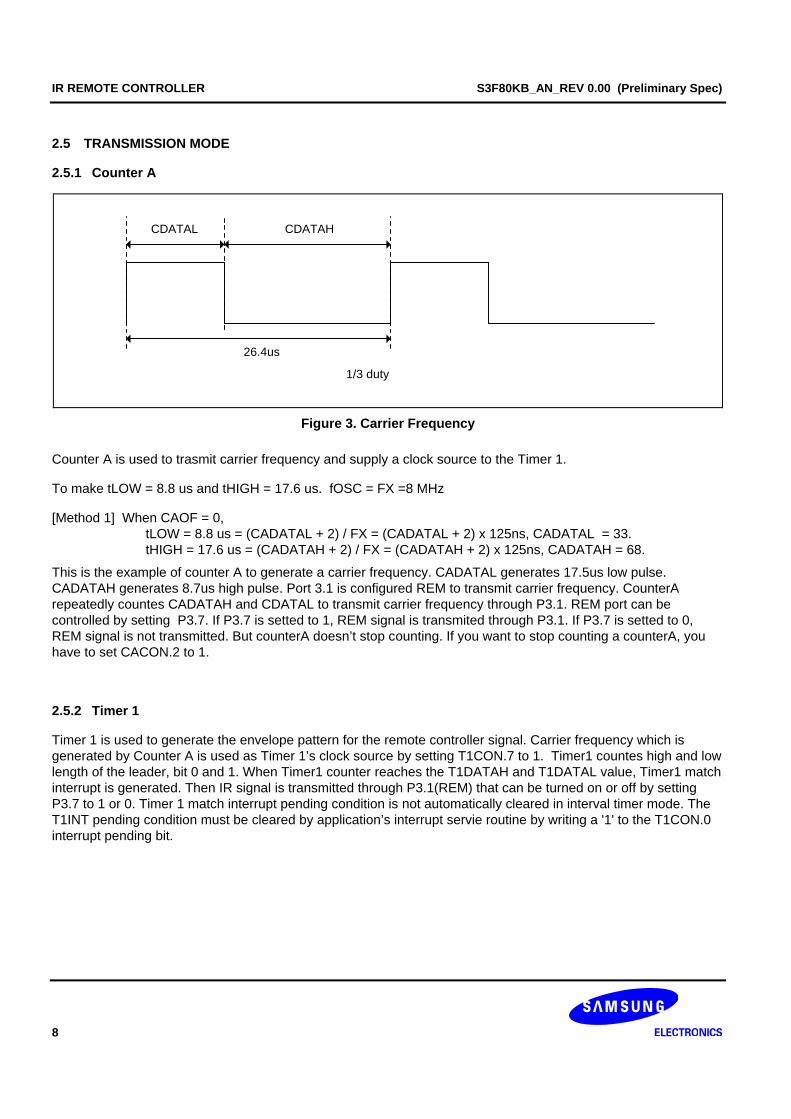
Figure 3. Carrier Frequency
Counter A is used to trasmit carrier frequency and supply a clock source to the Timer 1.
To make tLOW = 8.8 us and tHIGH = 17.6 us. fOSC = FX =8 MHz
[Method 1] When CAOF = 0, tLOW = 8.8 us = (CADATAL + 2) / FX = (CADATAL + 2) x 125ns, CADATAL = 33. tHIGH = 17.6 us = (CADATAH + 2) / FX = (CADATAH + 2) x 125ns, CADATAH = 68.
This is the example of counter A to generate a carrier frequency. CADATAL generates 17.5us low pulse. CADATAH generates 8.7us high pulse. Port 3.1 is configured REM to transmit carrier frequency. CounterA repeatedly countes CADATAH and CDATAL to transmit carrier frequency through P3.1. REM port can be controlled by setting P3.7. If P3.7 is setted to 1, REM signal is transmited through P3.1. If P3.7 is setted to 0, REM signal is not transmitted. But counterA doesn’t stop counting. If you want to stop counting a counterA, you have to set CACON.2 to 1.
2.5.2 Timer 1
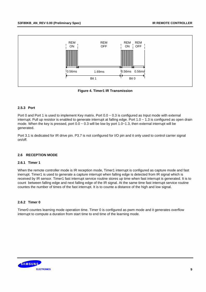
Timer 1 is used to generate the envelope pattern for the remote controller signal. Carrier frequency which is generated by Counter A is used as Timer 1’s clock source by setting T1CON.7 to 1. Timer1 countes high and low length of the leader, bit 0 and 1. When Timer1 counter reaches the T1DATAH and T1DATAL value, Timer1 match interrupt is generated. Then IR signal is transmitted through P3.1(REM) that can be turned on or off by setting P3.7 to 1 or 0. Timer 1 match interrupt pending condition is not automatically cleared in interval timer mode. The T1INT pending condition must be cleared by application’s interrupt servie routine by writing a '1' to the T1CON.0 interrupt pending bit.
S3F80KB_AN_REV 0.00 (Preliminary Spec) IR REMOTE CONTROLLER
9
Bit 1 Bit 0
0.56ms 1.69ms 0.56ms 0.56ms
REMON
REMOFF
REMOFF
REMON
Figure 4. Timer1 IR Transmission
2.5.3 Port
Port 0 and Port 1 is used to implement Key matrix. Port 0.0 ~ 0.3 is configured as Input mode with external interrupt. Pull up resistor is enabled to generate interrupt at falling edge. Port 1.0 ~ 1.3 is configured as open drain mode. When the key is pressed, port 0.0 ~ 0.3 will be low by port 1.0~1.3, then external interrupt will be generated.
Port 3.1 is dedicated for IR drive pin. P3.7 is not configured for I/O pin and it only used to control carrier signal on/off.
2.6 RECEPTION MODE
2.6.1 Timer 1
When the remote controller mode is IR reception mode, Timer1 interrupt is configured as capture mode and fast inerrupt. Timer1 is used to generate a capture interrupt when falling edge is detected from IR signal which is received by IR sensor. Timer1 fast interrupt service routine stores up time when fast interrupt is generated. It is to count between falling edge and next falling edge of the IR signal. At the same time fast interrupt service routine countes the number of times of the fast interrupt. It is to counte a distance of the high and low signal.
2.6.2 Timer 0
Timer0 countes learning mode operation time. Timer 0 is configured as pwm mode and it generates overflow interrupt to compute a duration from start time to end time of the learning mode.
IR REMOTE CONTROLLER S3F80KB_AN_REV 0.00 (Preliminary Spec)
10
3 SOFTWARE IMPLEMENTATION
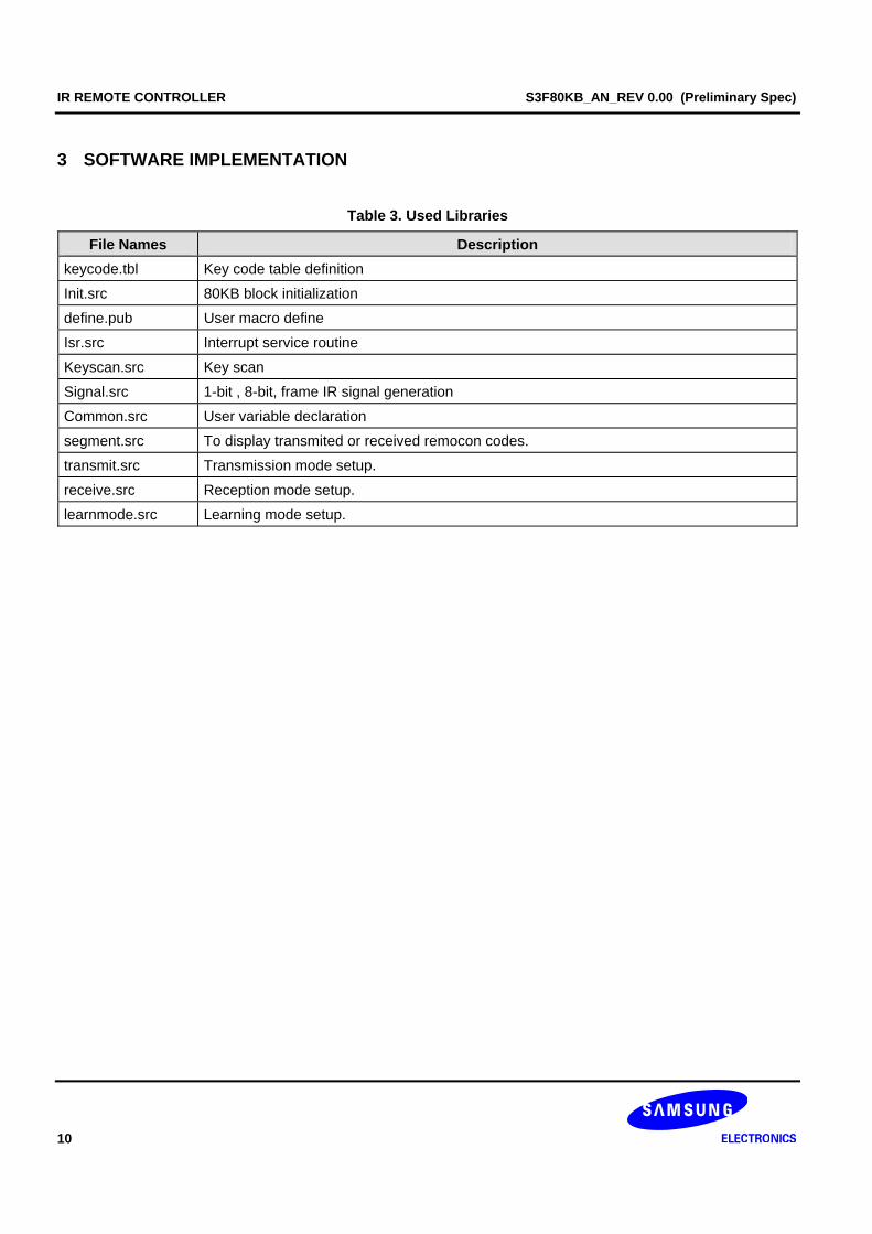
Table 3. Used Libraries
File Names Description keycode.tbl Key code table definition
Init.src 80KB block initialization
define.pub User macro define
Isr.src Interrupt service routine
Keyscan.src Key scan
Signal.src 1-bit , 8-bit, frame IR signal generation
Common.src User variable declaration
segment.src To display transmited or received remocon codes.
transmit.src Transmission mode setup.
receive.src Reception mode setup.
learnmode.src Learning mode setup.
S3F80KB_AN_REV 0.00 (Preliminary Spec) IR REMOTE CONTROLLER
11
3.1 TRANSMISSION MODULE
3.1.1 IR Transmission Description
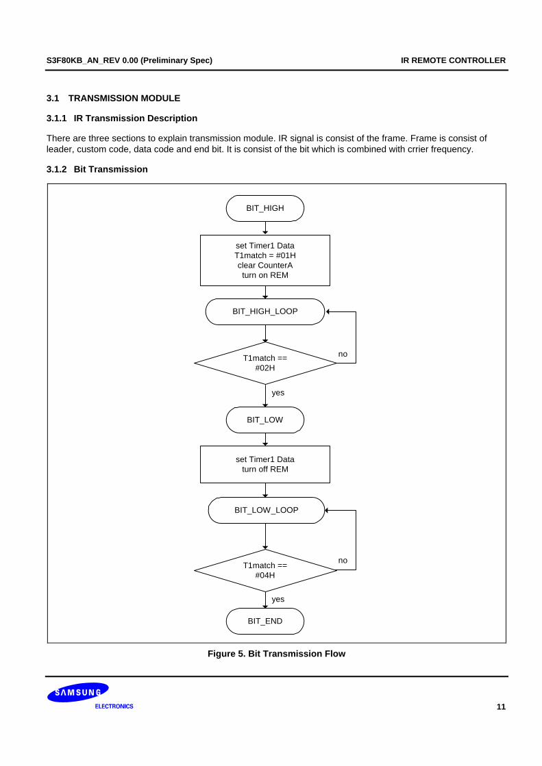
There are three sections to explain transmission module. IR signal is consist of the frame. Frame is consist of leader, custom code, data code and end bit. It is consist of the bit which is combined with crrier frequency.
3.1.2 Bit Transmission
set Timer1 DataT1match = #01Hclear CounterAturn on REM
BIT_HIGH
BIT_HIGH_LOOP
T1match ==#02H
BIT_LOW
BIT_LOW_LOOP
T1match ==#04H
set Timer1 Dataturn off REM
BIT_END
yes
no
yes
no
Figure 5. Bit Transmission Flow
IR REMOTE CONTROLLER S3F80KB_AN_REV 0.00 (Preliminary Spec)
12
Bit 0 or Bit 1 Transmission Module
Bit transmission module is used to transmit bit 0 or bit 1. Timer1's T1DATAH and T1DATAL value have to be setted before this module is used. SIGNAL_1BIT_PERIOD can be used to set that value. If SIGNAL_1BIT_PERIOD is setted, Timer1 countes until the match interrupt is generated. This code turn on REM during high sinal and turn off REM during low signal.
S3F80KB_AN_REV 0.00 (Preliminary Spec) IR REMOTE CONTROLLER
13
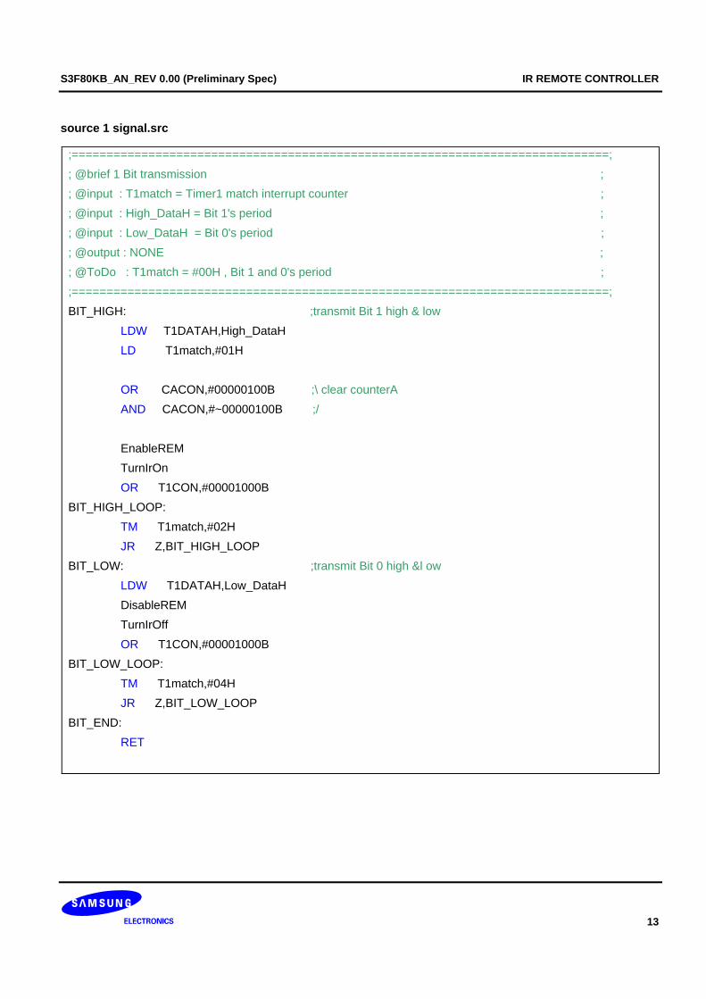
source 1 signal.src
;=============================================================================; ; @brief 1 Bit transmission ; ; @input : T1match = Timer1 match interrupt counter ; ; @input : High_DataH = Bit 1's period ; ; @input : Low_DataH = Bit 0's period ; ; @output : NONE ; ; @ToDo : T1match = #00H , Bit 1 and 0's period ; ;=============================================================================; BIT_HIGH: ;transmit Bit 1 high & low LDW T1DATAH,High_DataH LD T1match,#01H OR CACON,#00000100B ;\ clear counterA AND CACON,#~00000100B ;/ EnableREM TurnIrOn OR T1CON,#00001000B BIT_HIGH_LOOP: TM T1match,#02H JR Z,BIT_HIGH_LOOP BIT_LOW: ;transmit Bit 0 high &l ow LDW T1DATAH,Low_DataH DisableREM TurnIrOff OR T1CON,#00001000B BIT_LOW_LOOP: TM T1match,#04H JR Z,BIT_LOW_LOOP BIT_END: RET
IR REMOTE CONTROLLER S3F80KB_AN_REV 0.00 (Preliminary Spec)
14
3.2 8-BIT TRANSMISSION
Shift right rotate R3
TRANSMIT_8BIT
TRANSMIT_8BIT_1
carry bit == 1yes
no
TRANSMIT_8BIT_0
TRANSMIT_8BIT_COUNT
R0 == 0
decrease R0
Call Bit 1 transmit
Call Bit 0 transmit
no
RET
yes
Figure 6. 8-Bit Transmission Flow
S3F80KB_AN_REV 0.00 (Preliminary Spec) IR REMOTE CONTROLLER
15
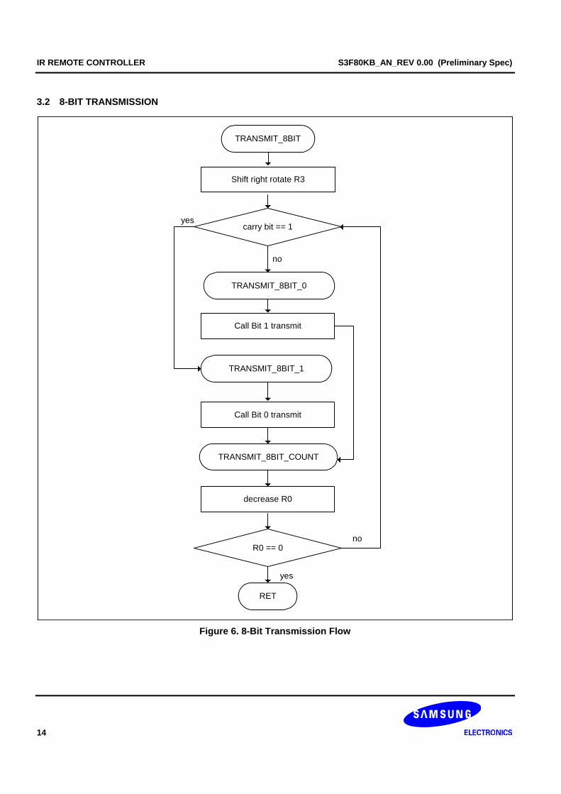
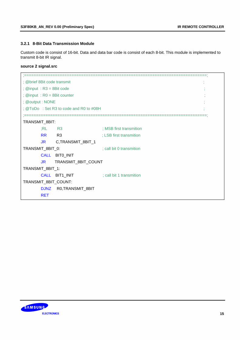
3.2.1 8-Bit Data Transmission Module
Custom code is consist of 16-bit. Data and data bar code is consist of each 8-bit. This module is implemented to transmit 8-bit IR signal.
source 2 signal.src
;=============================================================================; ; @brief 8Bit code transmit ; ; @input : R3 = 8Bit code ; ; @input : R0 = 8Bit counter ; ; @output : NONE ; ; @ToDo : Set R3 to code and R0 to #08H ; ;=============================================================================; TRANSMIT_8BIT: ;RL R3 ; MSB first transmition RR R3 ; LSB first transmition JR C,TRANSMIT_8BIT_1 TRANSMIT_8BIT_0: ; call bit 0 transmition CALL BIT0_INIT JR TRANSMIT_8BIT_COUNT TRANSMIT_8BIT_1: CALL BIT1_INIT ; call bit 1 transmition TRANSMIT_8BIT_COUNT: DJNZ R0,TRANSMIT_8BIT RET
IR REMOTE CONTROLLER S3F80KB_AN_REV 0.00 (Preliminary Spec)
16
3.3 FRAME TRANSMISSION
yes
no
DATA_REPEAT
DATA_TRANSMIT
R1 = #02HR3 = KEY_DATA
R0 = #08HCall TRANSMIT_8BIT
R3 = KEY_DATA
R1 == 0
DATABAR_TRASMIT
R3 = KEY_DATAreverse R3
ENDBIT_TRASMIT
Call BIT_HIGH
RET
Call Leader transmit
LEADER_TRANSMIT
R1 == 0
CUSTOM_TRANSMIT
R1 = #02H
CUSTOM_REPEAT
R0 = #08HR3 = KEY_CUSTOMCall TRANSMIT_8BIT
no
yes
Figure 7. Frame Transmission Flow
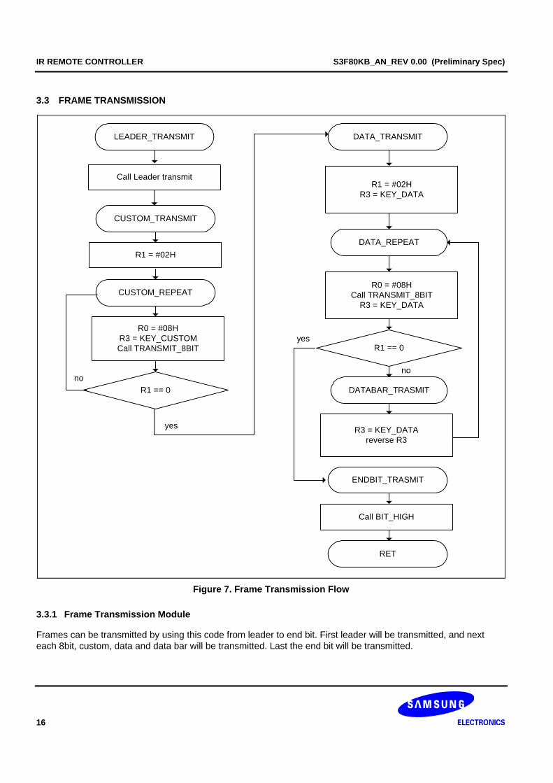
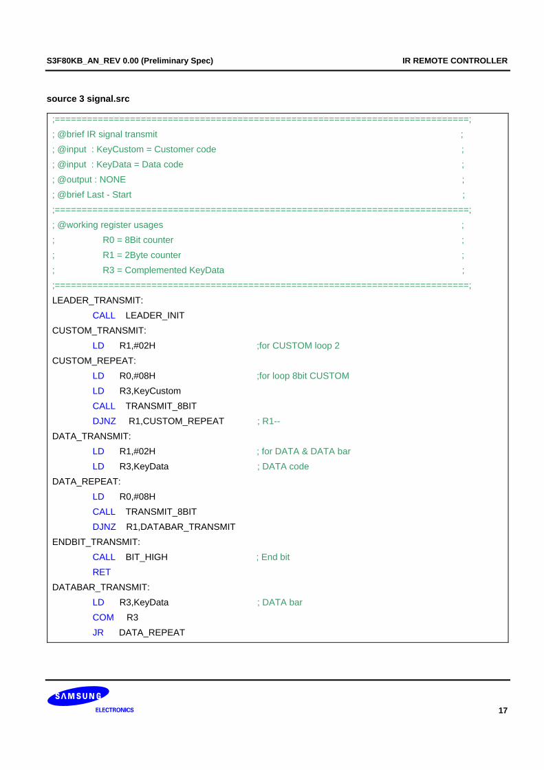
3.3.1 Frame Transmission Module
Frames can be transmitted by using this code from leader to end bit. First leader will be transmitted, and next each 8bit, custom, data and data bar will be transmitted. Last the end bit will be transmitted.
S3F80KB_AN_REV 0.00 (Preliminary Spec) IR REMOTE CONTROLLER
17
source 3 signal.src
;=============================================================================; ; @brief IR signal transmit ; ; @input : KeyCustom = Customer code ; ; @input : KeyData = Data code ; ; @output : NONE ; ; @brief Last - Start ; ;=============================================================================; ; @working register usages ; ; R0 = 8Bit counter ; ; R1 = 2Byte counter ; ; R3 = Complemented KeyData ; ;=============================================================================; LEADER_TRANSMIT: CALL LEADER_INIT CUSTOM_TRANSMIT: LD R1,#02H ;for CUSTOM loop 2 CUSTOM_REPEAT: LD R0,#08H ;for loop 8bit CUSTOM LD R3,KeyCustom CALL TRANSMIT_8BIT DJNZ R1,CUSTOM_REPEAT ; R1-- DATA_TRANSMIT: LD R1,#02H ; for DATA & DATA bar LD R3,KeyData ; DATA code DATA_REPEAT: LD R0,#08H CALL TRANSMIT_8BIT DJNZ R1,DATABAR_TRANSMIT ENDBIT_TRANSMIT: CALL BIT_HIGH ; End bit RET DATABAR_TRANSMIT: LD R3,KeyData ; DATA bar COM R3 JR DATA_REPEAT
IR REMOTE CONTROLLER S3F80KB_AN_REV 0.00 (Preliminary Spec)
18
3.4 IR RECEPTION MODULE
3.4.1 IR reception description
• Port 3.3 is configured as Timer1 Capture mode and falling edge interrupt. Timer1 is configured fast interrupt by setted SYM.
• When fast interrupt is generated, fast interrupt service routine increase the counter and calcurates leader length and every bit length. It will check limit of each signal length. If the signal is wrong, it exit from this routine.
• If all frame is normally received, it cofirmes data correction. Custom code compare each other and data code compare with a complemented data bar.
• If this data does not have error, the data code will be stored at pressed keypad buffer and data flag will be set to 1. (This is to transmit stored data code next time)
• Whenever Timer0 overflow interrupt is generated, it will increase a counter variable. If this counter is exceeded a learning mode limit, It will exit from learning mode.
S3F80KB_AN_REV 0.00 (Preliminary Spec) IR REMOTE CONTROLLER
19
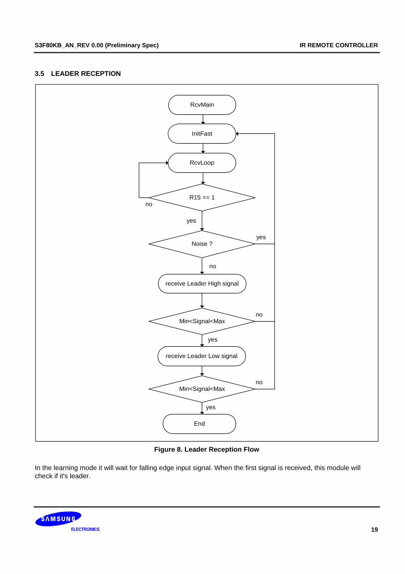
3.5 LEADER RECEPTION
RcvLoop
receive Leader High signal
End
Noise ?
R15 == 1
receive Leader Low signal
Min<Signal<Max
Min<Signal<Max
yes
no
yes
no
yes
InitFast
no
no
yes
RcvMain
Figure 8. Leader Reception Flow
In the learning mode it will wait for falling edge input signal. When the first signal is received, this module will check if it's leader.
IR REMOTE CONTROLLER S3F80KB_AN_REV 0.00 (Preliminary Spec)
20
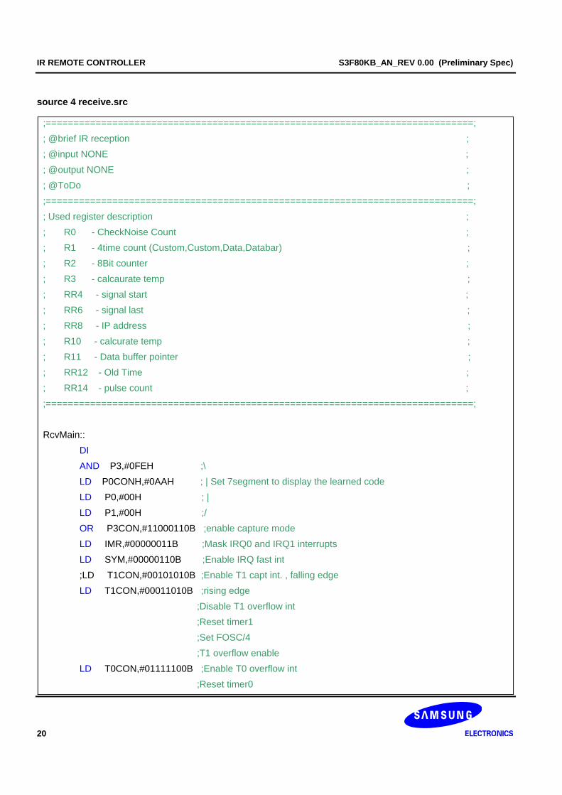
source 4 receive.src
;=============================================================================; ; @brief IR reception ; ; @input NONE ; ; @output NONE ; ; @ToDo ; ;=============================================================================; ; Used register description ; ; R0 - CheckNoise Count ; ; R1 - 4time count (Custom,Custom,Data,Databar) ; ; R2 - 8Bit counter ; ; R3 - calcaurate temp ; ; RR4 - signal start ; ; RR6 - signal last ; ; RR8 - IP address ; ; R10 - calcurate temp ; ; R11 - Data buffer pointer ; ; RR12 - Old Time ; ; RR14 - pulse count ; ;=============================================================================; RcvMain:: DI AND P3,#0FEH ;\ LD P0CONH,#0AAH ; | Set 7segment to display the learned code LD P0,#00H ; | LD P1,#00H ;/ OR P3CON,#11000110B ;enable capture mode LD IMR,#00000011B ;Mask IRQ0 and IRQ1 interrupts LD SYM,#00000110B ;Enable IRQ fast int ;LD T1CON,#00101010B ;Enable T1 capt int. , falling edge LD T1CON,#00011010B ;rising edge ;Disable T1 overflow int ;Reset timer1 ;Set FOSC/4 ;T1 overflow enable LD T0CON,#01111100B ;Enable T0 overflow int ;Reset timer0
S3F80KB_AN_REV 0.00 (Preliminary Spec) IR REMOTE CONTROLLER
21
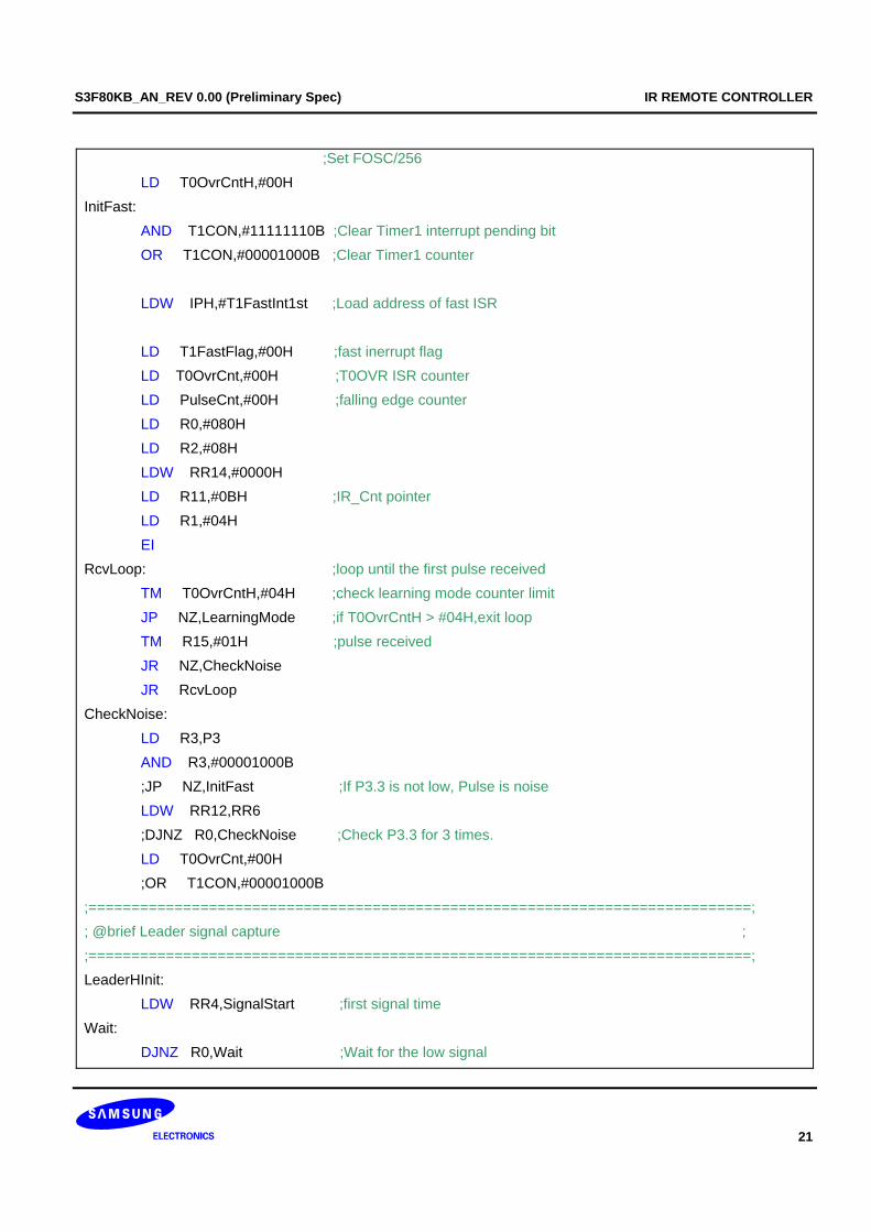
;Set FOSC/256 LD T0OvrCntH,#00H InitFast: AND T1CON,#11111110B ;Clear Timer1 interrupt pending bit OR T1CON,#00001000B ;Clear Timer1 counter LDW IPH,#T1FastInt1st ;Load address of fast ISR LD T1FastFlag,#00H ;fast inerrupt flag LD T0OvrCnt,#00H ;T0OVR ISR counter LD PulseCnt,#00H ;falling edge counter LD R0,#080H LD R2,#08H LDW RR14,#0000H LD R11,#0BH ;IR_Cnt pointer LD R1,#04H EI RcvLoop: ;loop until the first pulse received TM T0OvrCntH,#04H ;check learning mode counter limit JP NZ,LearningMode ;if T0OvrCntH > #04H,exit loop TM R15,#01H ;pulse received JR NZ,CheckNoise JR RcvLoop CheckNoise: LD R3,P3 AND R3,#00001000B ;JP NZ,InitFast ;If P3.3 is not low, Pulse is noise LDW RR12,RR6 ;DJNZ R0,CheckNoise ;Check P3.3 for 3 times. LD T0OvrCnt,#00H ;OR T1CON,#00001000B ;=============================================================================; ; @brief Leader signal capture ; ;=============================================================================; LeaderHInit: LDW RR4,SignalStart ;first signal time Wait: DJNZ R0,Wait ;Wait for the low signal
IR REMOTE CONTROLLER S3F80KB_AN_REV 0.00 (Preliminary Spec)
22
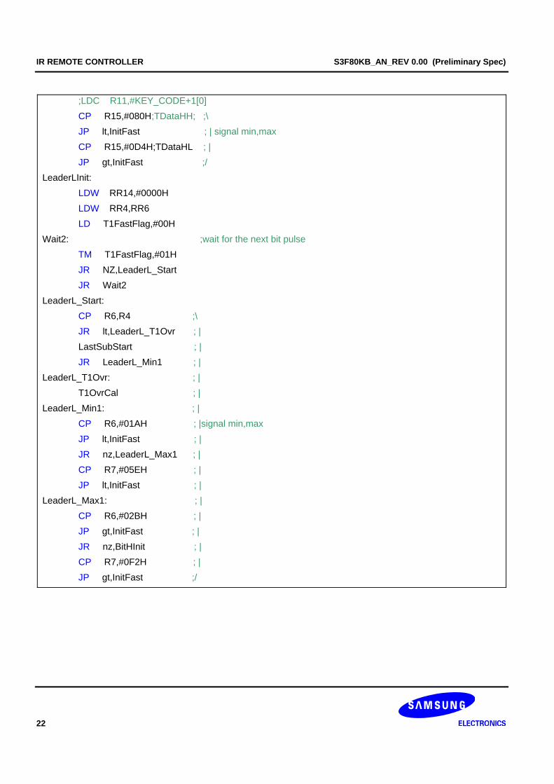
;LDC R11,#KEY_CODE+1[0] CP R15,#080H;TDataHH; ;\ JP lt,InitFast ; | signal min,max CP R15,#0D4H;TDataHL ; | JP gt,InitFast ;/ LeaderLInit: LDW RR14,#0000H LDW RR4,RR6 LD T1FastFlag,#00H Wait2: ;wait for the next bit pulse TM T1FastFlag,#01H JR NZ,LeaderL_Start JR Wait2 LeaderL_Start: CP R6,R4 ;\ JR lt,LeaderL_T1Ovr ; | LastSubStart ; | JR LeaderL_Min1 ; | LeaderL_T1Ovr: ; | T1OvrCal ; | LeaderL_Min1: ; | CP R6,#01AH ; |signal min,max JP lt,InitFast ; | JR nz,LeaderL_Max1 ; | CP R7,#05EH ; | JP lt,InitFast ; | LeaderL_Max1: ; | CP R6,#02BH ; | JP gt,InitFast ; | JR nz,BitHInit ; | CP R7,#0F2H ; | JP gt,InitFast ;/

S3F80KB_AN_REV 0.00 (Preliminary Spec) IR REMOTE CONTROLLER
23
3.6 DATA BIT RECEPTION
receive High signal
End
receive Low 0 signal
Signal Limit?
Min<Signal<Max
BitHInit
receive Low 1 signal
Min<Signal<Max
save bit 0
save bit 1
repeat 32Bit
check data
yes
yes
no
no
Figure 9. Bit Reception Flow
IR REMOTE CONTROLLER S3F80KB_AN_REV 0.00 (Preliminary Spec)
24
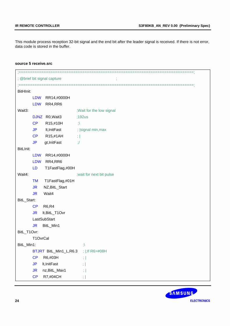
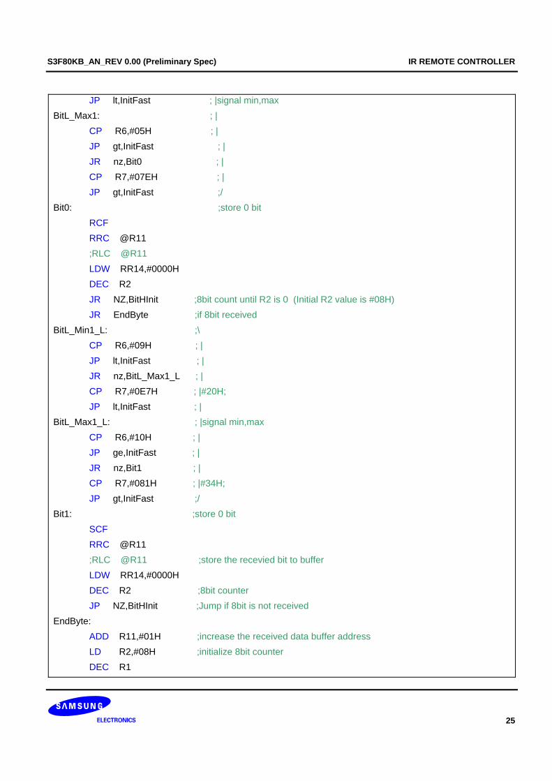
This module process reception 32-bit signal and the end bit after the leader signal is received. If there is not error, data code is stored in the buffer.
source 5 receive.src
;=============================================================================; ; @brief bit signal capture ; ;=============================================================================; BitHInit: LDW RR14,#0000H LDW RR4,RR6 Wait3: ;Wait for the low signal DJNZ R0,Wait3 ;192us CP R15,#10H ;\ JP lt,InitFast ; |signal min,max CP R15,#1AH ; | JP gt,InitFast ;/ BitLInit: LDW RR14,#0000H LDW RR4,RR6 LD T1FastFlag,#00H Wait4: ;wait for next bit pulse TM T1FastFlag,#01H JR NZ,BitL_Start JR Wait4 BitL_Start: CP R6,R4 JR lt,BitL_T1Ovr LastSubStart JR BitL_Min1 BitL_T1Ovr: T1OvrCal BitL_Min1: ;\ BTJRT BitL_Min1_L,R6.3 ; |;If R6>#08H CP R6,#03H ; | JP lt,InitFast ; | JR nz,BitL_Max1 ; | CP R7,#04CH ; |
S3F80KB_AN_REV 0.00 (Preliminary Spec) IR REMOTE CONTROLLER
25
JP lt,InitFast ; |signal min,max BitL_Max1: ; | CP R6,#05H ; | JP gt,InitFast ; | JR nz,Bit0 ; | CP R7,#07EH ; | JP gt,InitFast ;/ Bit0: ;store 0 bit RCF RRC @R11 ;RLC @R11 LDW RR14,#0000H DEC R2 JR NZ,BitHInit ;8bit count until R2 is 0 (Initial R2 value is #08H) JR EndByte ;if 8bit received BitL_Min1_L: ;\ CP R6,#09H ; | JP lt,InitFast ; | JR nz,BitL_Max1_L ; | CP R7,#0E7H ; |#20H; JP lt,InitFast ; | BitL_Max1_L: ; |signal min,max CP R6,#10H ; | JP ge,InitFast ; | JR nz,Bit1 ; | CP R7,#081H ; |#34H; JP gt,InitFast ;/ Bit1: ;store 0 bit SCF RRC @R11 ;RLC @R11 ;store the recevied bit to buffer LDW RR14,#0000H DEC R2 ;8bit counter JP NZ,BitHInit ;Jump if 8bit is not received EndByte: ADD R11,#01H ;increase the received data buffer address LD R2,#08H ;initialize 8bit counter DEC R1
IR REMOTE CONTROLLER S3F80KB_AN_REV 0.00 (Preliminary Spec)
26
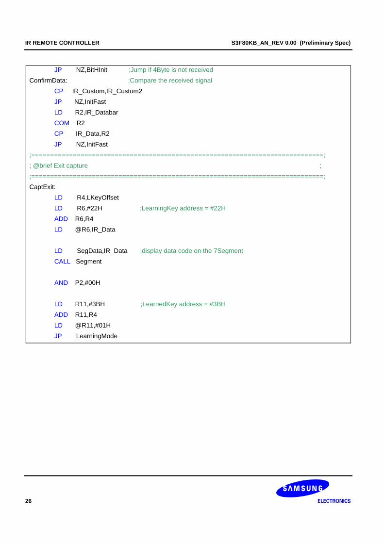
JP NZ,BitHInit ;Jump if 4Byte is not received ConfirmData: ;Compare the received signal CP IR_Custom,IR_Custom2 JP NZ,InitFast LD R2,IR_Databar COM R2 CP IR_Data,R2 JP NZ,InitFast ;=============================================================================; ; @brief Exit capture ; ;=============================================================================; CaptExit: LD R4,LKeyOffset LD R6,#22H ;LearningKey address = #22H ADD R6,R4 LD @R6,IR_Data LD SegData,IR_Data ;display data code on the 7Segment CALL Segment AND P2,#00H LD R11,#3BH ;LearnedKey address = #3BH ADD R11,R4 LD @R11,#01H JP LearningMode
S3F80KB_AN_REV 0.00 (Preliminary Spec) IR REMOTE CONTROLLER
27
4 TEST METHOD
MCU MCU
Test board 1 Test board 2
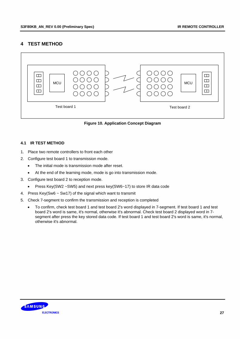
Figure 10. Application Concept Diagram
4.1 IR TEST METHOD
1. Place two remote controllers to front each other
2. Configure test board 1 to transmission mode.
• The initial mode is transmission mode after reset.
• At the end of the learning mode, mode is go into transmission mode.
3. Configure test board 2 to reception mode.
• Press Key(SW2 ~SW5) and next press key(SW6~17) to store IR data code
4. Press Key(Sw6 ~ Sw17) of the signal which want to transmit
5. Check 7-segment to confirm the transmission and reception is completed
• To confirm, check test board 1 and test board 2's word displayed in 7-segment. If test board 1 and test board 2's word is same, it's normal, otherwise it's abnormal. Check test board 2 displayed word in 7-segment after press the key stored data code. If test board 1 and test board 2's word is same, it's normal, otherwise it's abnormal.
IR REMOTE CONTROLLER S3F80KB_AN_REV 0.00 (Preliminary Spec)
28
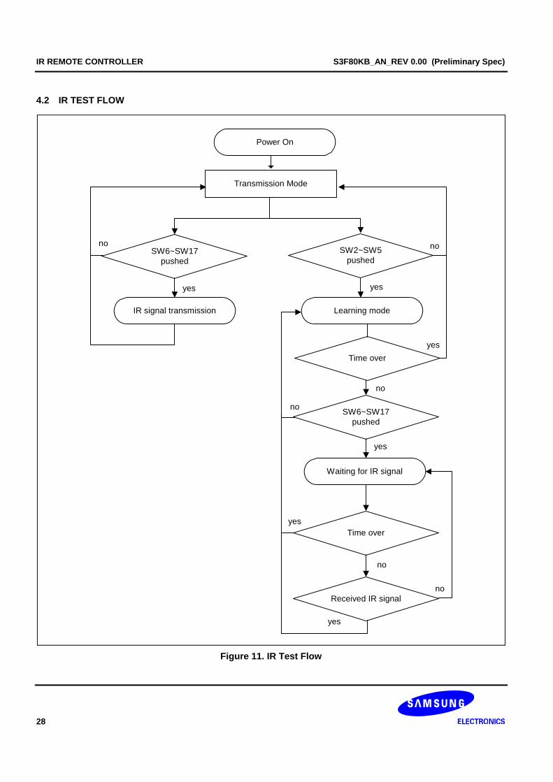
4.2 IR TEST FLOW
Transmission Mode
Learning mode
SW6~SW17pushed
yes
Power On
SW2~SW5pushed
SW6~SW17pushed
Waiting for IR signal
IR signal transmission
Received IR signal
Time over
no
no
yes
no
no
yes
Time over
yes
yes
no
no
yes
Figure 11. IR Test Flow
S3F80KB_AN_REV 0.00 (Preliminary Spec) IR REMOTE CONTROLLER
29
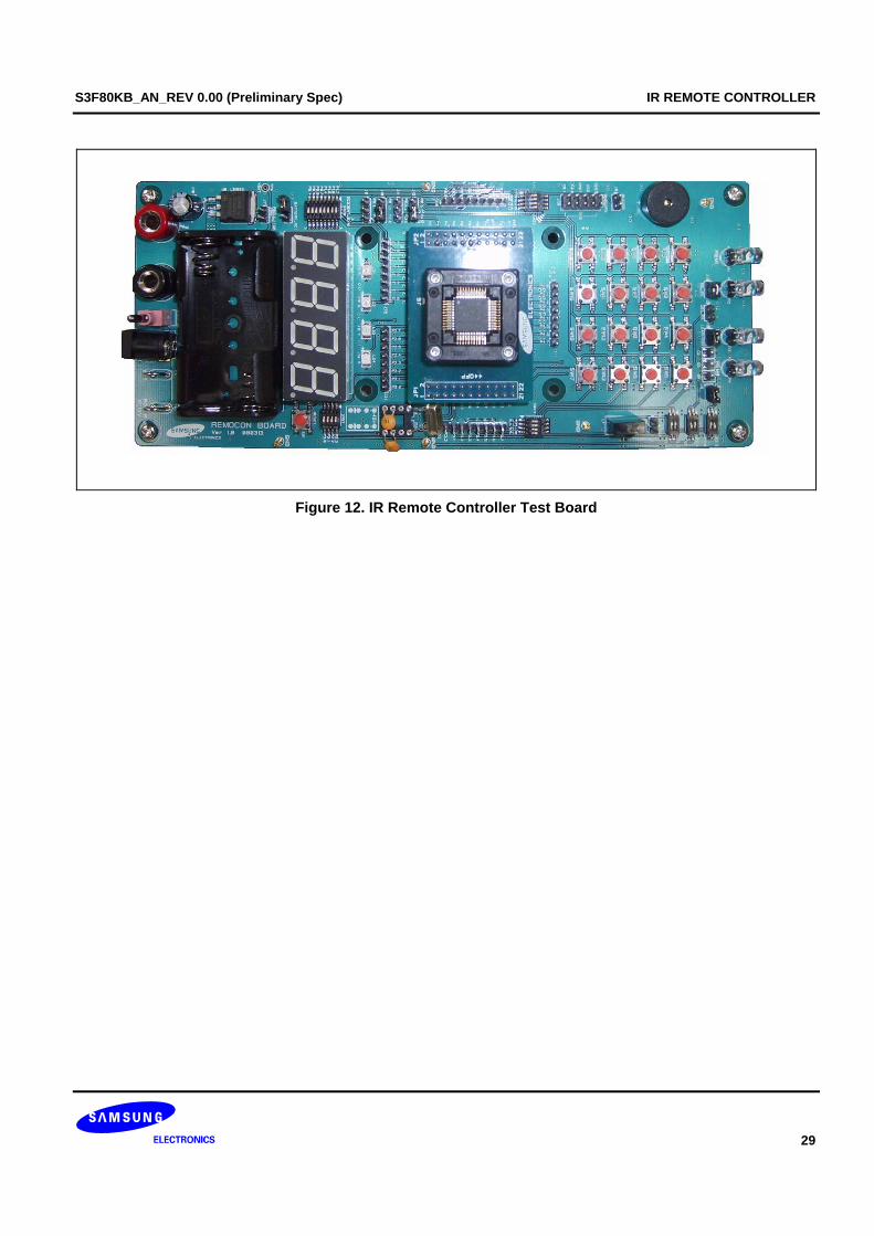
Figure 12. IR Remote Controller Test Board
IR REMOTE CONTROLLER S3F80KB_AN_REV 0.00 (Preliminary Spec)
30
NOTES