Embed Size (px)
Citation preview
Radar (FMCW) Level Transmitter for bypass chambers and magnetic level indicators (BM 26 Advanced)
OPTIWAVE 1010OPTIWAVE 1010OPTIWAVE 1010OPTIWAVE 1010 HandbookHandbookHandbookHandbook
© KROHNE 10/2015 - 4003537402 - MA OPTIWAVE 1010 R02 en

All rights reserved. It is prohibited to reproduce this documentation, or any part thereof, without
the prior written authorisation of KROHNE Messtechnik GmbH.
Subject to change without notice.
2 www.krohne.com 10/2015 - 4003537402 - MA OPTIWAVE 1010 R02 en
Copyright 2015 by
KROHNE Messtechnik GmbH - Ludwig-Krohne-Str. 5 - 47058 Duisburg (Germany)
: IMPRINT :::::::::::::::::::::::::::::::::::::::
CONTENTS
3www.krohne.com10/2015 - 4003537402 - MA OPTIWAVE 1010 R02 en
OPTIWAVE 1010
1 Safety instructions 6
1.1 Software history ............................................................................................................... 61.2 Intended use ..................................................................................................................... 61.3 Certification ...................................................................................................................... 71.4 Electromagnetic compatibility ......................................................................................... 71.5 Radio approvals ................................................................................................................ 8
1.5.1 European Union (EU)............................................................................................................... 81.5.2 U.S.A. and Canada................................................................................................................... 9
1.6 Safety instructions from the manufacturer ................................................................... 101.6.1 Copyright and data protection .............................................................................................. 101.6.2 Disclaimer ............................................................................................................................. 101.6.3 Product liability and warranty .............................................................................................. 111.6.4 Information concerning the documentation......................................................................... 111.6.5 Warnings and symbols used................................................................................................. 12
1.7 Safety instructions for the operator............................................................................... 12
2 Device description 13
2.1 Scope of delivery............................................................................................................. 132.2 Device description .......................................................................................................... 132.3 Visual Check ................................................................................................................... 142.4 Nameplates .................................................................................................................... 15
2.4.1 Nameplate (example)............................................................................................................ 15
3 Installation 16
3.1 General notes on installation ......................................................................................... 163.2 Storage ........................................................................................................................... 163.3 Transport ........................................................................................................................ 173.4 Pre-installation requirements ....................................................................................... 173.5 Pressure and temperature ranges ................................................................................ 183.6 Recommended mounting position ................................................................................. 213.7 Mounting restrictions ..................................................................................................... 223.8 How to attach the weather protection to the device ...................................................... 223.9 How to open the weather protection.............................................................................. 25
4 Electrical connections 26
4.1 Safety instructions.......................................................................................................... 264.2 Electrical installation: 2-wire, loop-powered ................................................................ 264.3 Electrical connection for current output ....................................................................... 27
4.3.1 Non-Ex devices ..................................................................................................................... 274.3.2 Devices for hazardous locations........................................................................................... 27
4.4 Protection category ........................................................................................................ 284.5 Networks ........................................................................................................................ 29
4.5.1 General information.............................................................................................................. 294.5.2 Point-to-point connection..................................................................................................... 294.5.3 Multi-drop networks ............................................................................................................. 30
CONTENTS
4 www.krohne.com 10/2015 - 4003537402 - MA OPTIWAVE 1010 R02 en
OPTIWAVE 1010
5 Start-up 31
5.1 How to start the device................................................................................................... 315.1.1 Start-up checklist ................................................................................................................. 315.1.2 How to start the device ......................................................................................................... 31
5.2 Operating concept .......................................................................................................... 315.3 Remote communication with PACTware™ .................................................................... 32
5.3.1 General notes........................................................................................................................ 325.3.2 Software installation............................................................................................................. 335.3.3 Measurements window......................................................................................................... 345.3.4 Analysis window.................................................................................................................... 355.3.5 Diagnosis window.................................................................................................................. 385.3.6 Simulation window................................................................................................................ 39
6 Operation 40
6.1 Software configuration ................................................................................................... 406.1.1 General notes........................................................................................................................ 406.1.2 Procedure.............................................................................................................................. 40
6.2 How to load settings from the device to PACTware™ ................................................... 416.3 How to store settings to the device from PACTware™.................................................. 436.4 Menu overview................................................................................................................ 456.5 How to change device settings....................................................................................... 466.6 Data about parameters (online Help)............................................................................. 476.7 Device settings ............................................................................................................... 48
6.7.1 Password protection for device settings .............................................................................. 486.7.2 Import / Export...................................................................................................................... 496.7.3 Information............................................................................................................................ 516.7.4 Basic parameters.................................................................................................................. 526.7.5 Current output ...................................................................................................................... 536.7.6 Application............................................................................................................................. 556.7.7 Application: Float offset calculation ..................................................................................... 566.7.8 HART...................................................................................................................................... 576.7.9 DTM settings ......................................................................................................................... 58
6.8 Status and error messages............................................................................................ 596.8.1 Device status ......................................................................................................................... 596.8.2 Error handling....................................................................................................................... 60
7 Service 62
7.1 Periodic maintenance..................................................................................................... 627.2 How to replace device components ............................................................................... 62
7.2.1 Service warranty ................................................................................................................... 627.2.2 How to replace the signal converter .................................................................................... 63
7.3 Spare parts availability................................................................................................... 647.4 Availability of services .................................................................................................... 657.5 Returning the device to the manufacturer..................................................................... 65
7.5.1 General information.............................................................................................................. 657.5.2 Form (for copying) to accompany a returned device............................................................ 66
7.6 Disposal .......................................................................................................................... 66
CONTENTS
5www.krohne.com10/2015 - 4003537402 - MA OPTIWAVE 1010 R02 en
OPTIWAVE 1010
8 Technical data 67
8.1 Measuring principle........................................................................................................ 678.2 Technical data................................................................................................................. 688.3 Measuring accuracy ....................................................................................................... 728.4 Minimum power supply voltage ..................................................................................... 738.5 Dimensions and weights ................................................................................................ 74
9 Description of HART interface 76
9.1 General description ........................................................................................................ 769.2 Software description ...................................................................................................... 769.3 Connection variants........................................................................................................ 77
9.3.1 Point-to-Point connection - analogue / digital mode........................................................... 779.3.2 Multi-Drop connection (2-wire connection) ......................................................................... 77
9.4 HART® device variables................................................................................................. 779.5 Field Communicator 475 (FC 475).................................................................................. 78
9.5.1 Installation ............................................................................................................................ 789.5.2 Operation............................................................................................................................... 78
9.6 Field Device Tool / Device Type Manager (FDT / DTM).................................................. 789.6.1 Installation ............................................................................................................................ 789.6.2 Operation............................................................................................................................... 78
9.7 HART® menu tree for Basic-DD .................................................................................... 799.7.1 Overview Basic-DD menu tree (positions in menu tree)...................................................... 799.7.2 Basic-DD menu tree (details for settings)............................................................................ 79
10 Appendix 81
10.1 Order code .................................................................................................................... 8110.2 Spare parts ................................................................................................................... 8310.3 Accessories................................................................................................................... 8410.4 Glossary ........................................................................................................................ 85
11 Notes 87
1 SAFETY INSTRUCTIONS
6
OPTIWAVE 1010
www.krohne.com 10/2015 - 4003537402 - MA OPTIWAVE 1010 R02 en
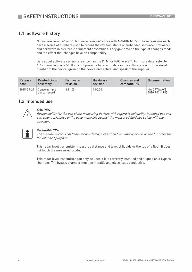
1.1 Software history
"Firmware revision" and "Hardware revision" agree with NAMUR NE 53. These revisions each have a series of numbers used to record the revision status of embedded software (firmware) and hardware in electronic equipment assemblies. They give data on the type of changes made and the effect that changes have on compatibility.
Data about software revisions is shown in the DTM for PACTware™. For more data, refer to Information on page 51. If it is not possible to refer to data in the software, record the serial number of the device (given on the device nameplate) and speak to the supplier.
1.2 Intended use
This radar level transmitter measures distance and level of liquids or the top of a float. It does not touch the measured product.
This radar level transmitter can only be used if it is correctly installed and aligned on a bypass chamber. The bypass chamber must be metallic and electrically conductive.
Release date
Printed circuit assembly
Firmware revision
Hardware revision
Changes and compatibility
Documentation
2015-05-27 Converter and sensor board
8.11.00 1.00.00 — MA OPTIWAVE 1010 R01 + R02
CAUTION!Responsibility for the use of the measuring devices with regard to suitability, intended use and corrosion resistance of the used materials against the measured fluid lies solely with the operator.
INFORMATION!The manufacturer is not liable for any damage resulting from improper use or use for other than the intended purpose.
SAFETY INSTRUCTIONS 1
7
OPTIWAVE 1010
www.krohne.com10/2015 - 4003537402 - MA OPTIWAVE 1010 R02 en
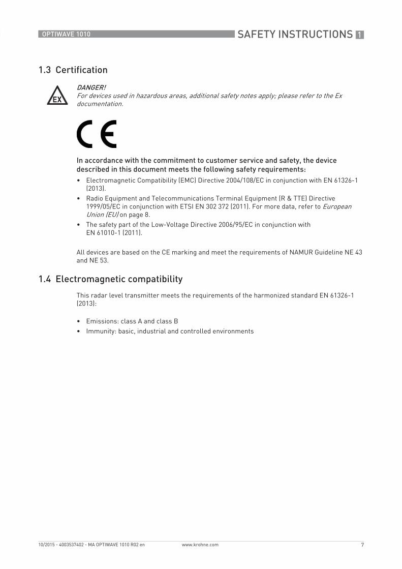
1.3 Certification
In accordance with the commitment to customer service and safety, the device described in this document meets the following safety requirements:• Electromagnetic Compatibility (EMC) Directive 2004/108/EC in conjunction with EN 61326-1
(2013).• Radio Equipment and Telecommunications Terminal Equipment (R & TTE) Directive
1999/05/EC in conjunction with ETSI EN 302 372 (2011). For more data, refer to European Union (EU) on page 8.
• The safety part of the Low-Voltage Directive 2006/95/EC in conjunction with EN 61010-1 (2011).
All devices are based on the CE marking and meet the requirements of NAMUR Guideline NE 43 and NE 53.
1.4 Electromagnetic compatibility
This radar level transmitter meets the requirements of the harmonized standard EN 61326-1 (2013):
• Emissions: class A and class B• Immunity: basic, industrial and controlled environments
DANGER!For devices used in hazardous areas, additional safety notes apply; please refer to the Ex documentation.
1 SAFETY INSTRUCTIONS
8
OPTIWAVE 1010
www.krohne.com 10/2015 - 4003537402 - MA OPTIWAVE 1010 R02 en
1.5 Radio approvals
1.5.1 European Union (EU)
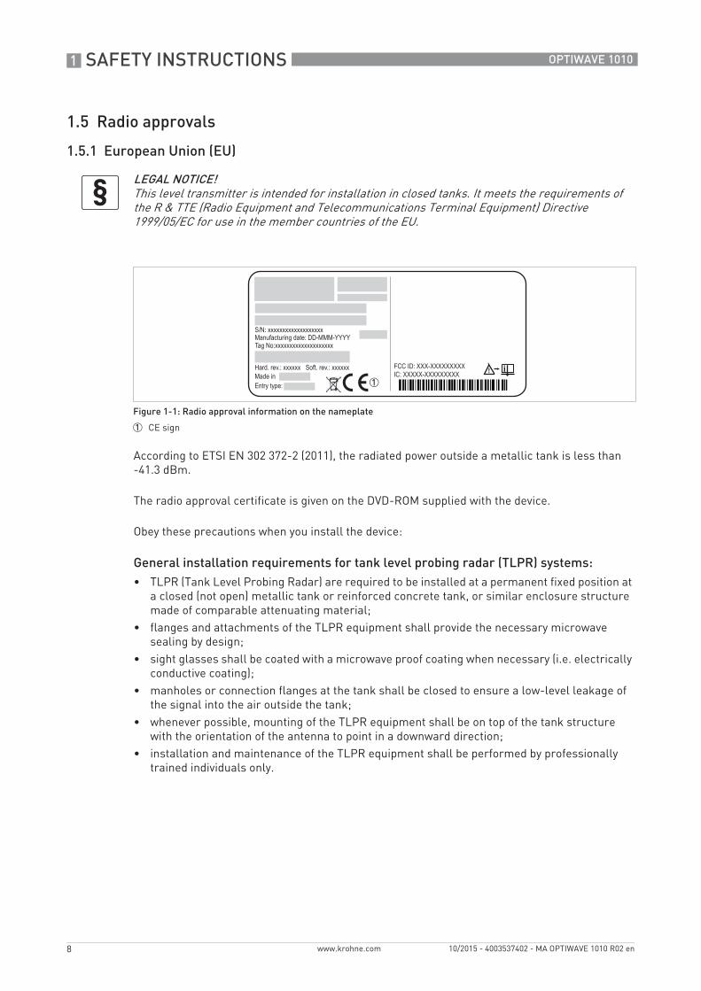
According to ETSI EN 302 372-2 (2011), the radiated power outside a metallic tank is less than -41.3 dBm.
The radio approval certificate is given on the DVD-ROM supplied with the device.
Obey these precautions when you install the device:
General installation requirements for tank level probing radar (TLPR) systems:• TLPR (Tank Level Probing Radar) are required to be installed at a permanent fixed position at
a closed (not open) metallic tank or reinforced concrete tank, or similar enclosure structure made of comparable attenuating material;
• flanges and attachments of the TLPR equipment shall provide the necessary microwave sealing by design;
• sight glasses shall be coated with a microwave proof coating when necessary (i.e. electrically conductive coating);
• manholes or connection flanges at the tank shall be closed to ensure a low-level leakage of the signal into the air outside the tank;
• whenever possible, mounting of the TLPR equipment shall be on top of the tank structure with the orientation of the antenna to point in a downward direction;
• installation and maintenance of the TLPR equipment shall be performed by professionally trained individuals only.
LEGAL NOTICE!This level transmitter is intended for installation in closed tanks. It meets the requirements of the R & TTE (Radio Equipment and Telecommunications Terminal Equipment) Directive 1999/05/EC for use in the member countries of the EU.
Figure 1-1: Radio approval information on the nameplate
1 CE sign

SAFETY INSTRUCTIONS 1
9
OPTIWAVE 1010
www.krohne.com10/2015 - 4003537402 - MA OPTIWAVE 1010 R02 en
1.5.2 U.S.A. and Canada
This legal information is shown on a label on the side of the device.
The radio approval report is given on the DVD-ROM supplied with the device.
LEGAL NOTICE!This device complies with Part 15 of the FCC Rules and with RSS-210 of Industry Canada. Operation is subject to the following two conditions:1. This device may not cause harmful interference, and2. This device must accept any interference received, including interference which may cause un-
desired operation.Changes or modifications made to this equipment not expressly approved by the manufacturer may void the FCC and IC authorizations to operate this equipment.
1 SAFETY INSTRUCTIONS
10
OPTIWAVE 1010
www.krohne.com 10/2015 - 4003537402 - MA OPTIWAVE 1010 R02 en
1.6 Safety instructions from the manufacturer
1.6.1 Copyright and data protection
The contents of this document have been created with great care. Nevertheless, we provide no guarantee that the contents are correct, complete or up-to-date.
The contents and works in this document are subject to copyright. Contributions from third parties are identified as such. Reproduction, processing, dissemination and any type of use beyond what is permitted under copyright requires written authorisation from the respective author and/or the manufacturer.
The manufacturer tries always to observe the copyrights of others, and to draw on works created in-house or works in the public domain.
The collection of personal data (such as names, street addresses or e-mail addresses) in the manufacturer's documents is always on a voluntary basis whenever possible. Whenever feasible, it is always possible to make use of the offerings and services without providing any personal data.
We draw your attention to the fact that data transmission over the Internet (e.g. when communicating by e-mail) may involve gaps in security. It is not possible to protect such data completely against access by third parties.
We hereby expressly prohibit the use of the contact data published as part of our duty to publish an imprint for the purpose of sending us any advertising or informational materials that we have not expressly requested.
1.6.2 Disclaimer
The manufacturer will not be liable for any damage of any kind by using its product, including, but not limited to direct, indirect or incidental and consequential damages.
This disclaimer does not apply in case the manufacturer has acted on purpose or with gross negligence. In the event any applicable law does not allow such limitations on implied warranties or the exclusion of limitation of certain damages, you may, if such law applies to you, not be subject to some or all of the above disclaimer, exclusions or limitations.
Any product purchased from the manufacturer is warranted in accordance with the relevant product documentation and our Terms and Conditions of Sale.
The manufacturer reserves the right to alter the content of its documents, including this disclaimer in any way, at any time, for any reason, without prior notification, and will not be liable in any way for possible consequences of such changes.
SAFETY INSTRUCTIONS 1
11
OPTIWAVE 1010
www.krohne.com10/2015 - 4003537402 - MA OPTIWAVE 1010 R02 en
1.6.3 Product liability and warranty
The operator shall bear responsibility for the suitability of the device for the specific purpose. The manufacturer accepts no liability for the consequences of misuse by the operator. Improper installation or operation of the devices (systems) will cause the warranty to be void. The respective "Standard Terms and Conditions" which form the basis for the sales contract shall also apply.
1.6.4 Information concerning the documentation
To prevent any injury to the user or damage to the device it is essential that you read the information in this document and observe applicable national standards, safety requirements and accident prevention regulations.
If this document is not in your native language and if you have any problems understanding the text, we advise you to contact your local office for assistance. The manufacturer can not accept responsibility for any damage or injury caused by misunderstanding of the information in this document.
This document is provided to help you establish operating conditions, which will permit safe and efficient use of this device. Special considerations and precautions are also described in the document, which appear in the form of icons as shown below.
1 SAFETY INSTRUCTIONS
12
OPTIWAVE 1010
www.krohne.com 10/2015 - 4003537402 - MA OPTIWAVE 1010 R02 en
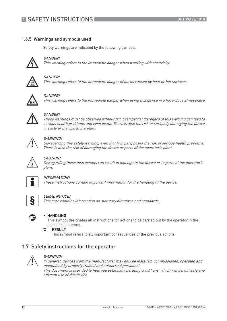
1.6.5 Warnings and symbols used
Safety warnings are indicated by the following symbols.
• HANDLINGHANDLINGHANDLINGHANDLINGThis symbol designates all instructions for actions to be carried out by the operator in the specified sequence.
i RESULTRESULTRESULTRESULTThis symbol refers to all important consequences of the previous actions.
1.7 Safety instructions for the operator
DANGER!This warning refers to the immediate danger when working with electricity.
DANGER!This warning refers to the immediate danger of burns caused by heat or hot surfaces.
DANGER!This warning refers to the immediate danger when using this device in a hazardous atmosphere.
DANGER!These warnings must be observed without fail. Even partial disregard of this warning can lead to serious health problems and even death. There is also the risk of seriously damaging the device or parts of the operator's plant.
WARNING!Disregarding this safety warning, even if only in part, poses the risk of serious health problems. There is also the risk of damaging the device or parts of the operator's plant.
CAUTION!Disregarding these instructions can result in damage to the device or to parts of the operator's plant.
INFORMATION!These instructions contain important information for the handling of the device.
LEGAL NOTICE!This note contains information on statutory directives and standards.
WARNING!In general, devices from the manufacturer may only be installed, commissioned, operated and maintained by properly trained and authorized personnel. This document is provided to help you establish operating conditions, which will permit safe and efficient use of this device.
DEVICE DESCRIPTION 2
13
OPTIWAVE 1010
www.krohne.com10/2015 - 4003537402 - MA OPTIWAVE 1010 R02 en
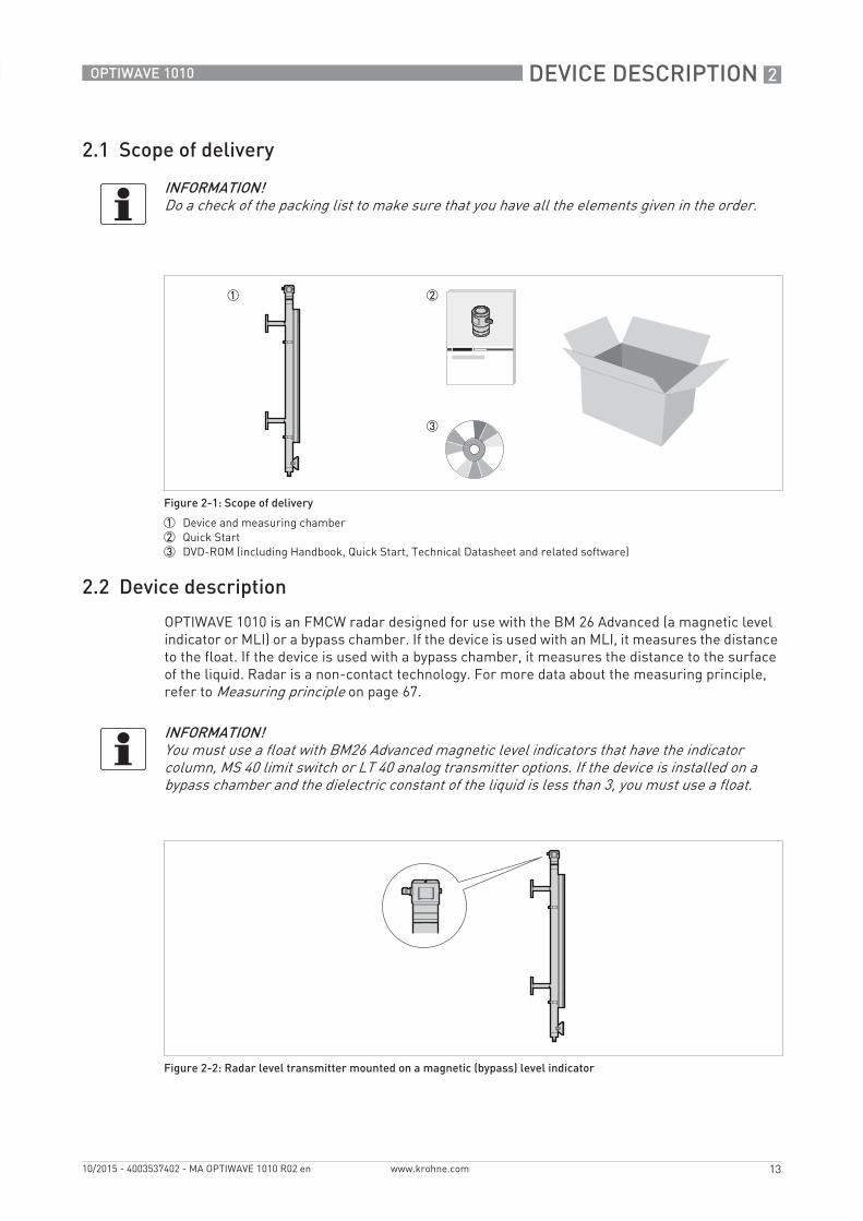
2.1 Scope of delivery
2.2 Device description
OPTIWAVE 1010 is an FMCW radar designed for use with the BM 26 Advanced (a magnetic level indicator or MLI) or a bypass chamber. If the device is used with an MLI, it measures the distance to the float. If the device is used with a bypass chamber, it measures the distance to the surface of the liquid. Radar is a non-contact technology. For more data about the measuring principle, refer to Measuring principle on page 67.
INFORMATION!Do a check of the packing list to make sure that you have all the elements given in the order.
Figure 2-1: Scope of delivery
1 Device and measuring chamber2 Quick Start3 DVD-ROM (including Handbook, Quick Start, Technical Datasheet and related software)
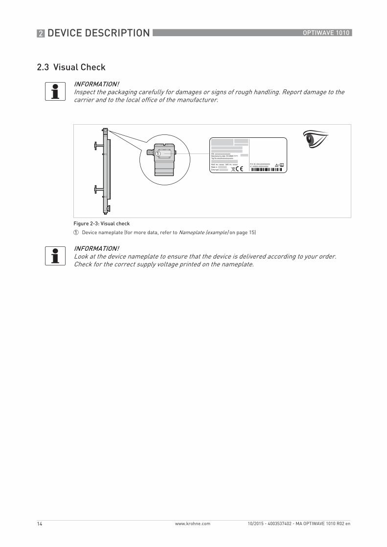
INFORMATION!You must use a float with BM26 Advanced magnetic level indicators that have the indicator column, MS 40 limit switch or LT 40 analog transmitter options. If the device is installed on a bypass chamber and the dielectric constant of the liquid is less than 3, you must use a float.
Figure 2-2: Radar level transmitter mounted on a magnetic (bypass) level indicator
2 DEVICE DESCRIPTION
14
OPTIWAVE 1010
www.krohne.com 10/2015 - 4003537402 - MA OPTIWAVE 1010 R02 en
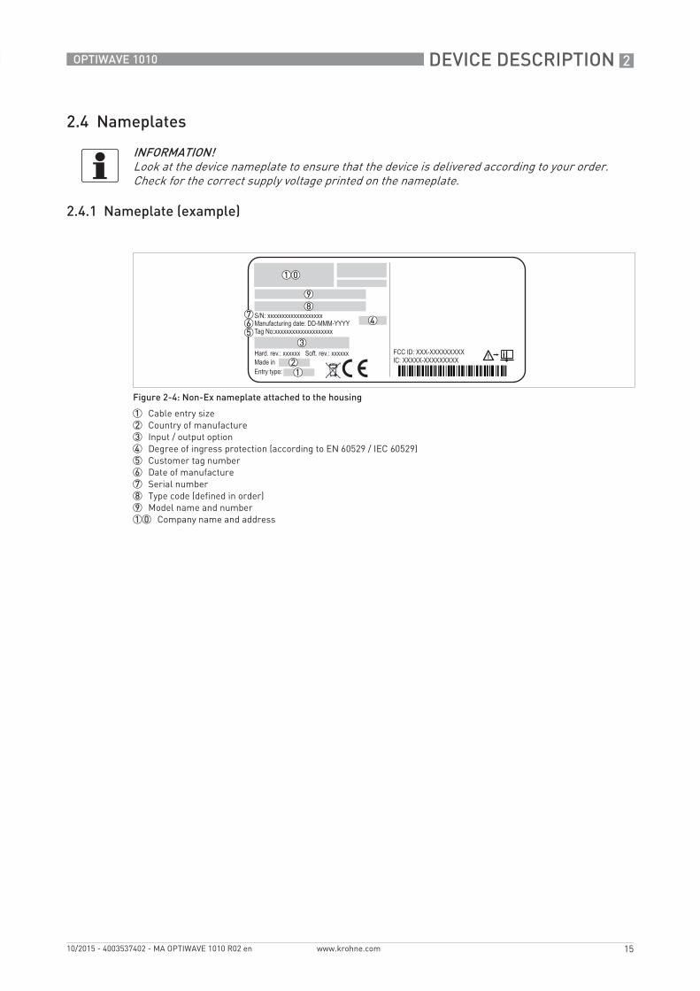
2.3 Visual Check
INFORMATION!Inspect the packaging carefully for damages or signs of rough handling. Report damage to the carrier and to the local office of the manufacturer.
Figure 2-3: Visual check
1 Device nameplate (for more data, refer to Nameplate (example) on page 15)
INFORMATION!Look at the device nameplate to ensure that the device is delivered according to your order. Check for the correct supply voltage printed on the nameplate.
DEVICE DESCRIPTION 2
15
OPTIWAVE 1010
www.krohne.com10/2015 - 4003537402 - MA OPTIWAVE 1010 R02 en
2.4 Nameplates
2.4.1 Nameplate (example)
INFORMATION!Look at the device nameplate to ensure that the device is delivered according to your order. Check for the correct supply voltage printed on the nameplate.
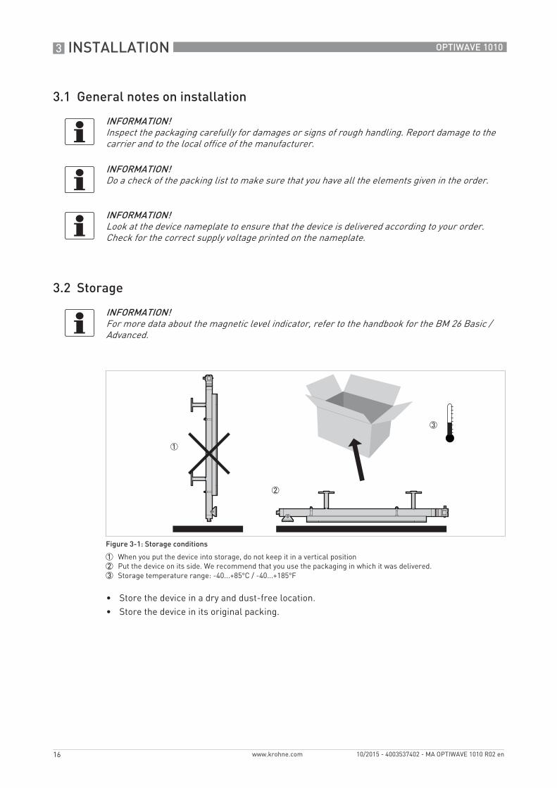
Figure 2-4: Non-Ex nameplate attached to the housing
1 Cable entry size2 Country of manufacture3 Input / output option4 Degree of ingress protection (according to EN 60529 / IEC 60529)5 Customer tag number6 Date of manufacture7 Serial number8 Type code (defined in order)9 Model name and number10 Company name and address
3 INSTALLATION
16
OPTIWAVE 1010
www.krohne.com 10/2015 - 4003537402 - MA OPTIWAVE 1010 R02 en
3.1 General notes on installation
3.2 Storage
• Store the device in a dry and dust-free location.• Store the device in its original packing.
INFORMATION!Inspect the packaging carefully for damages or signs of rough handling. Report damage to the carrier and to the local office of the manufacturer.
INFORMATION!Do a check of the packing list to make sure that you have all the elements given in the order.
INFORMATION!Look at the device nameplate to ensure that the device is delivered according to your order. Check for the correct supply voltage printed on the nameplate.
INFORMATION!For more data about the magnetic level indicator, refer to the handbook for the BM 26 Basic / Advanced.
Figure 3-1: Storage conditions
1 When you put the device into storage, do not keep it in a vertical position2 Put the device on its side. We recommend that you use the packaging in which it was delivered.3 Storage temperature range: -40...+85°C / -40...+185°F
INSTALLATION 3
17
OPTIWAVE 1010
www.krohne.com10/2015 - 4003537402 - MA OPTIWAVE 1010 R02 en
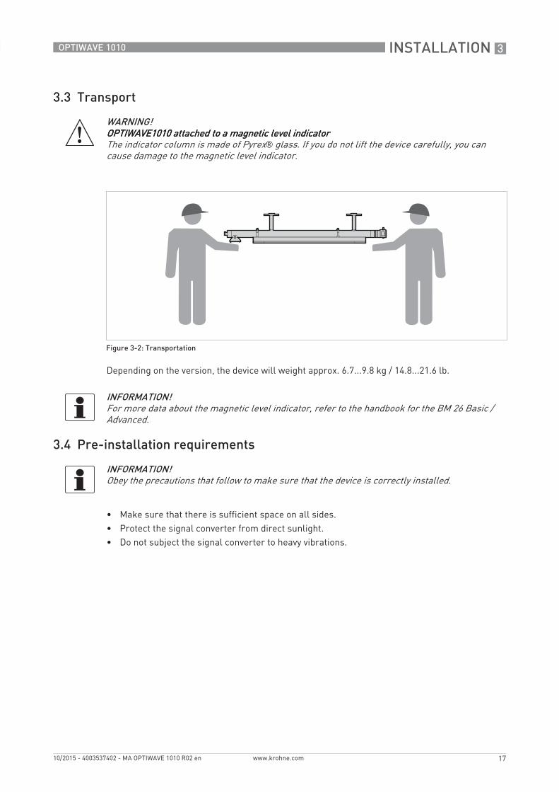
3.3 Transport
Depending on the version, the device will weight approx. 6.7...9.8 kg / 14.8...21.6 lb.
3.4 Pre-installation requirements
• Make sure that there is sufficient space on all sides.• Protect the signal converter from direct sunlight. • Do not subject the signal converter to heavy vibrations.
WARNING!OPTIWAVE1010 attached to a magnetic level indicatorOPTIWAVE1010 attached to a magnetic level indicatorOPTIWAVE1010 attached to a magnetic level indicatorOPTIWAVE1010 attached to a magnetic level indicatorThe indicator column is made of Pyrex® glass. If you do not lift the device carefully, you can cause damage to the magnetic level indicator.
Figure 3-2: Transportation
INFORMATION!For more data about the magnetic level indicator, refer to the handbook for the BM 26 Basic / Advanced.
INFORMATION!Obey the precautions that follow to make sure that the device is correctly installed.
3 INSTALLATION
18
OPTIWAVE 1010
www.krohne.com 10/2015 - 4003537402 - MA OPTIWAVE 1010 R02 en
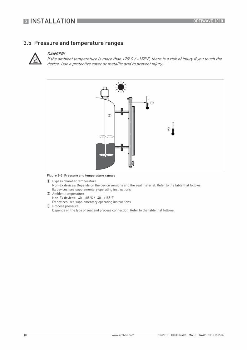
3.5 Pressure and temperature ranges
DANGER!If the ambient temperature is more than +70°C / +158°F, there is a risk of injury if you touch the device. Use a protective cover or metallic grid to prevent injury.
Figure 3-3: Pressure and temperature ranges
1 Bypass chamber temperatureNon-Ex devices: Depends on the device versions and the seal material. Refer to the table that follows.Ex devices: see supplementary operating instructions
2 Ambient temperatureNon-Ex devices: -40...+85°C / -40...+185°FEx devices: see supplementary operating instructions
3 Process pressureDepends on the type of seal and process connection. Refer to the table that follows.
INSTALLATION 3
19
OPTIWAVE 1010
www.krohne.com10/2015 - 4003537402 - MA OPTIWAVE 1010 R02 en
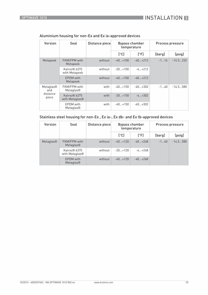
Aluminium housing for non-Ex and Ex ia-approved devices
Stainless steel housing for non-Ex , Ex ia-, Ex db- and Ex tb-approved devices
Version Seal Distance piece Bypass chamber temperature
Process pressure
[°C] [°F] [barg] [psig]
Metapeek FKM/FPM with Metapeek
without -40...+100 -40...+212 -1...16 -14.5...232
Kalrez® 6375 with Metapeek
without -20...+100 -4...+212
EPDM with Metapeek
without -40...+100 -40...+212
Metaglas® and
distance piece
FKM/FPM with Metaglas®
with -40...+150 -40...+302 -1...40 -14.5...580
Kalrez® 6375 with Metaglas®
with -20...+150 -4...+302
EPDM with Metaglas®
with -40...+150 -40...+302
Version Seal Distance piece Bypass chamber temperature
Process pressure
[°C] [°F] [barg] [psig]
Metaglas® FKM/FPM with Metaglas®
without -40...+120 -40...+248 -1...40 -14.5...580
Kalrez® 6375 with Metaglas®
without -20...+120 -4...+248
EPDM with Metaglas®
without -40...+120 -40...+248
3 INSTALLATION
20
OPTIWAVE 1010
www.krohne.com 10/2015 - 4003537402 - MA OPTIWAVE 1010 R02 en
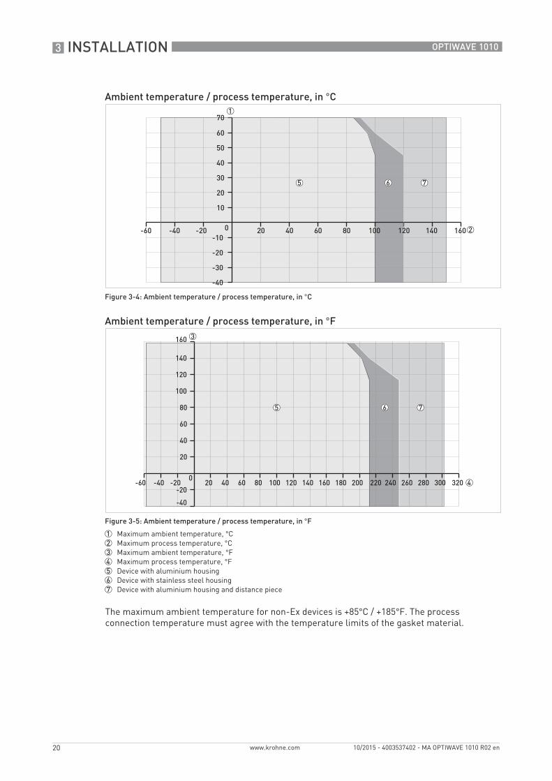
The maximum ambient temperature for non-Ex devices is +85°C / +185°F. The process connection temperature must agree with the temperature limits of the gasket material.
Ambient temperature / process temperature, in °C
Figure 3-4: Ambient temperature / process temperature, in °C
Ambient temperature / process temperature, in °F
Figure 3-5: Ambient temperature / process temperature, in °F
1 Maximum ambient temperature, °C2 Maximum process temperature, °C3 Maximum ambient temperature, °F4 Maximum process temperature, °F5 Device with aluminium housing6 Device with stainless steel housing7 Device with aluminium housing and distance piece
INSTALLATION 3
21
OPTIWAVE 1010
www.krohne.com10/2015 - 4003537402 - MA OPTIWAVE 1010 R02 en
3.6 Recommended mounting position
CAUTION!Follow these recommendations to make sure that the device measures correctly. They have an effect on the performance of the device.
CAUTION!Make sure that the cable glands are aligned with the process connections of the bypass chamber.
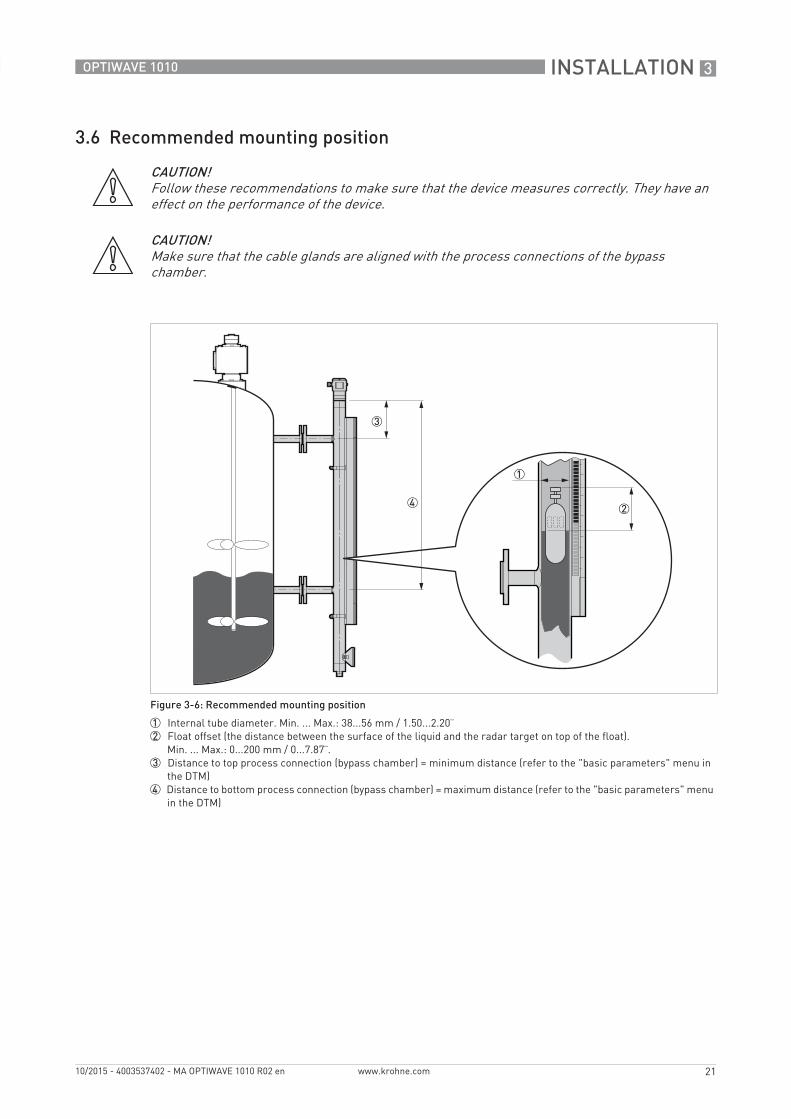
Figure 3-6: Recommended mounting position
1 Internal tube diameter. Min. ... Max.: 38...56 mm / 1.50...2.20¨2 Float offset (the distance between the surface of the liquid and the radar target on top of the float).
Min. ... Max.: 0...200 mm / 0...7.87¨.3 Distance to top process connection (bypass chamber) = minimum distance (refer to the "basic parameters" menu in
the DTM)4 Distance to bottom process connection (bypass chamber) = maximum distance (refer to the "basic parameters" menu
in the DTM)
3 INSTALLATION
22
OPTIWAVE 1010
www.krohne.com 10/2015 - 4003537402 - MA OPTIWAVE 1010 R02 en
3.7 Mounting restrictions
Follow these recommendations to make sure that the device measures correctly. They have an effect on the performance of the device.
3.8 How to attach the weather protection to the device
The device and the weather protection option are supplied assembled in the same box. If you send an order for the weather protection after delivery of the device, obey the instructions that follow:
WARNING!If the device uses a float to measure the level of the liquid, slowly pressurize the bypass chamber. A float can damage the PEEK cone of the radar level transmitter at the top of the bypass chamber.
CAUTION!If there are parasitic signals, the device will not measure correctly. Parasitic signals are caused by sudden changes in bypass chamber diameter in the path of the radar beam.
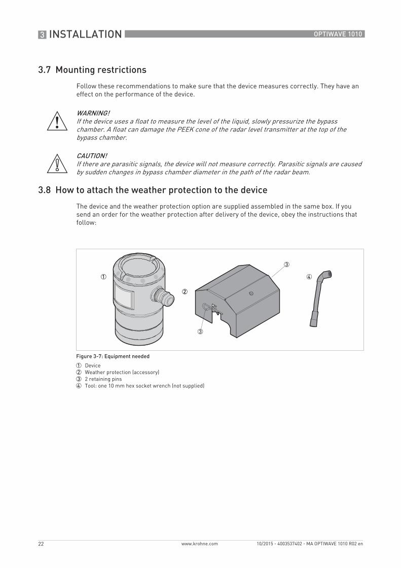
Figure 3-7: Equipment needed
1 Device2 Weather protection (accessory)3 2 retaining pins4 Tool: one 10 mm hex socket wrench (not supplied)
INSTALLATION 3
23
OPTIWAVE 1010
www.krohne.com10/2015 - 4003537402 - MA OPTIWAVE 1010 R02 en
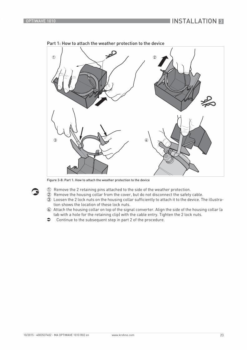
1 Remove the 2 retaining pins attached to the side of the weather protection.2 Remove the housing collar from the cover, but do not disconnect the safety cable.3 Loosen the 2 lock nuts on the housing collar sufficiently to attach it to the device. The illustra-
tion shows the location of these lock nuts.4 Attach the housing collar on top of the signal converter. Align the side of the housing collar (a
tab with a hole for the retaining clip) with the cable entry. Tighten the 2 lock nuts.i Continue to the subsequent step in part 2 of the procedure.
Part 1: How to attach the weather protection to the device
Figure 3-8: Part 1: How to attach the weather protection to the device
3 INSTALLATION
24
OPTIWAVE 1010
www.krohne.com 10/2015 - 4003537402 - MA OPTIWAVE 1010 R02 en
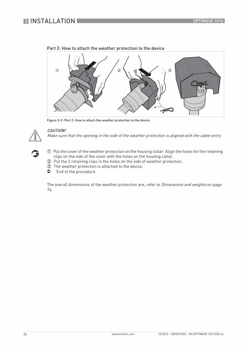
1 Put the cover of the weather protection on the housing collar. Align the holes for the retaining clips on the side of the cover with the holes on the housing collar.
2 Put the 2 retaining clips in the holes on the side of weather protection.3 The weather protection is attached to the device.i End of the procedure.
The overall dimensions of the weather protection are, refer to Dimensions and weights on page 74.
Part 2: How to attach the weather protection to the device
Figure 3-9: Part 2: How to attach the weather protection to the device
CAUTION!Make sure that the opening in the side of the weather protection is aligned with the cable entry.
INSTALLATION 3
25
OPTIWAVE 1010
www.krohne.com10/2015 - 4003537402 - MA OPTIWAVE 1010 R02 en
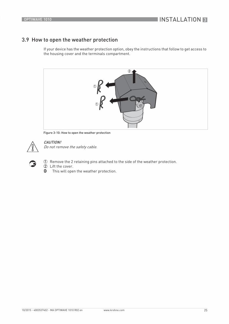
3.9 How to open the weather protection
If your device has the weather protection option, obey the instructions that follow to get access to the housing cover and the terminals compartment.
1 Remove the 2 retaining pins attached to the side of the weather protection.2 Lift the cover.i This will open the weather protection.
Figure 3-10: How to open the weather protection
CAUTION!Do not remove the safety cable.
4 ELECTRICAL CONNECTIONS
26
OPTIWAVE 1010
www.krohne.com 10/2015 - 4003537402 - MA OPTIWAVE 1010 R02 en
4.1 Safety instructions
4.2 Electrical installation: 2-wire, loop-powered
DANGER!All work on the electrical connections may only be carried out with the power disconnected. Take note of the voltage data on the nameplate!
DANGER!Observe the national regulations for electrical installations!
DANGER!For devices used in hazardous areas, additional safety notes apply; please refer to the Ex documentation.
WARNING!Observe without fail the local occupational health and safety regulations. Any work done on the electrical components of the measuring device may only be carried out by properly trained specialists.
INFORMATION!Look at the device nameplate to ensure that the device is delivered according to your order. Check for the correct supply voltage printed on the nameplate.
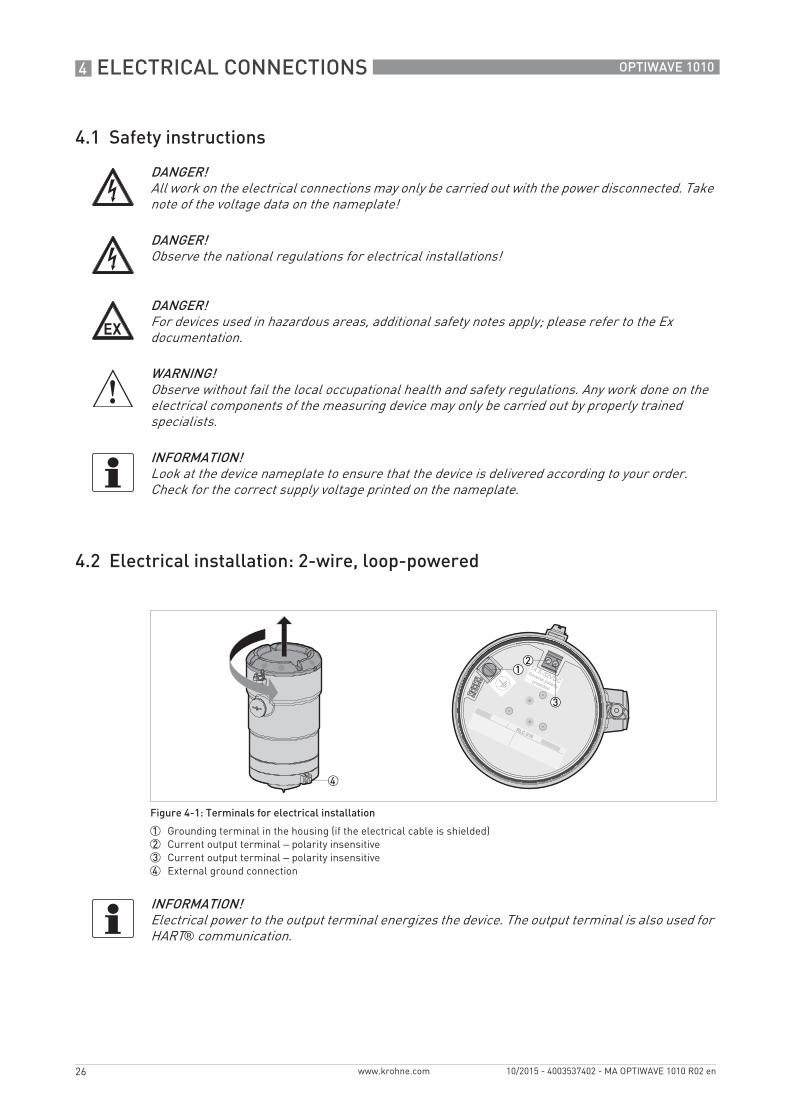
Figure 4-1: Terminals for electrical installation
1 Grounding terminal in the housing (if the electrical cable is shielded)2 Current output terminal – polarity insensitive3 Current output terminal – polarity insensitive4 External ground connection
INFORMATION!Electrical power to the output terminal energizes the device. The output terminal is also used for HART® communication.
ELECTRICAL CONNECTIONS 4
27
OPTIWAVE 1010
www.krohne.com10/2015 - 4003537402 - MA OPTIWAVE 1010 R02 en
4.3 Electrical connection for current output
4.3.1 Non-Ex devices
4.3.2 Devices for hazardous locations
CAUTION!Use the applicable electrical cables with the cable glands.
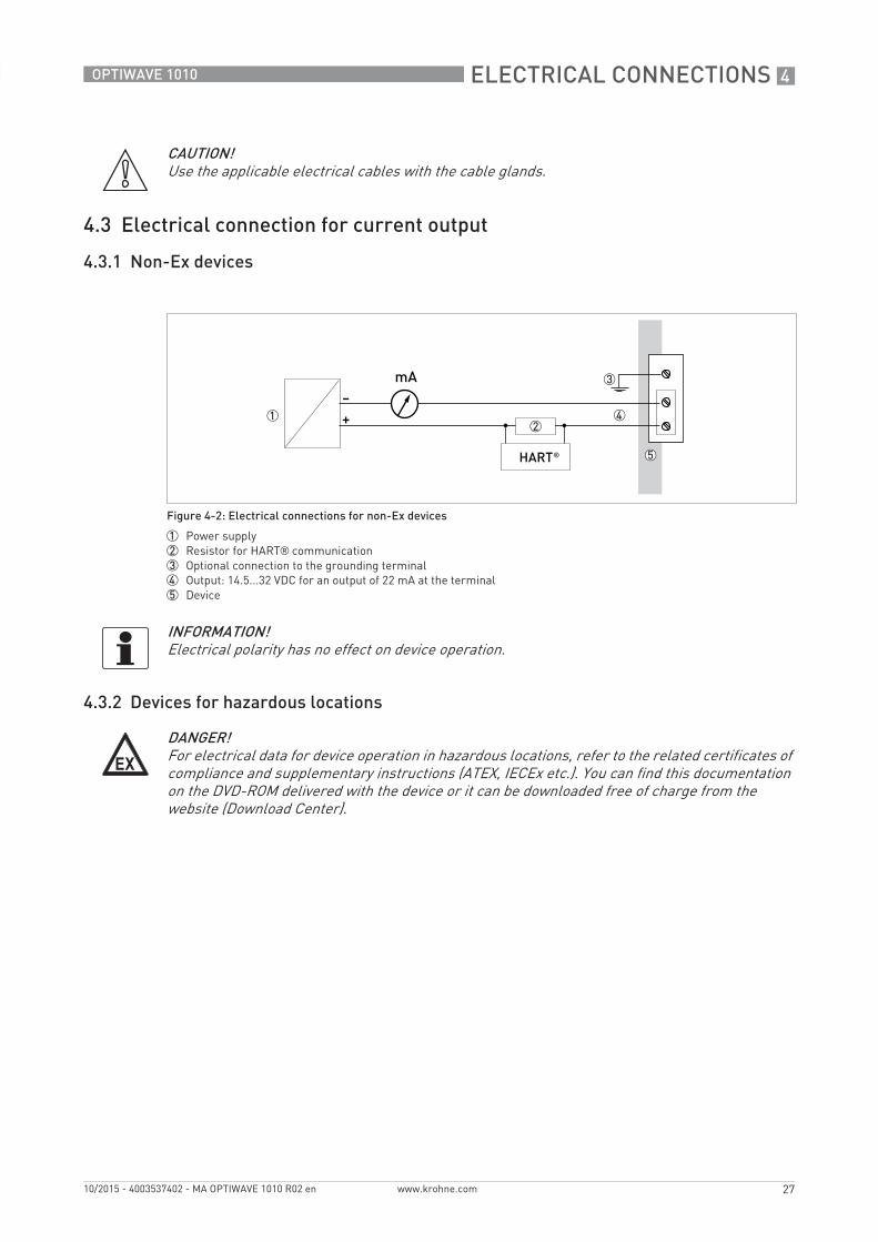
Figure 4-2: Electrical connections for non-Ex devices
1 Power supply2 Resistor for HART® communication3 Optional connection to the grounding terminal4 Output: 14.5...32 VDC for an output of 22 mA at the terminal5 Device
INFORMATION!Electrical polarity has no effect on device operation.
DANGER!For electrical data for device operation in hazardous locations, refer to the related certificates of compliance and supplementary instructions (ATEX, IECEx etc.). You can find this documentation on the DVD-ROM delivered with the device or it can be downloaded free of charge from the website (Download Center).
4 ELECTRICAL CONNECTIONS
28
OPTIWAVE 1010
www.krohne.com 10/2015 - 4003537402 - MA OPTIWAVE 1010 R02 en
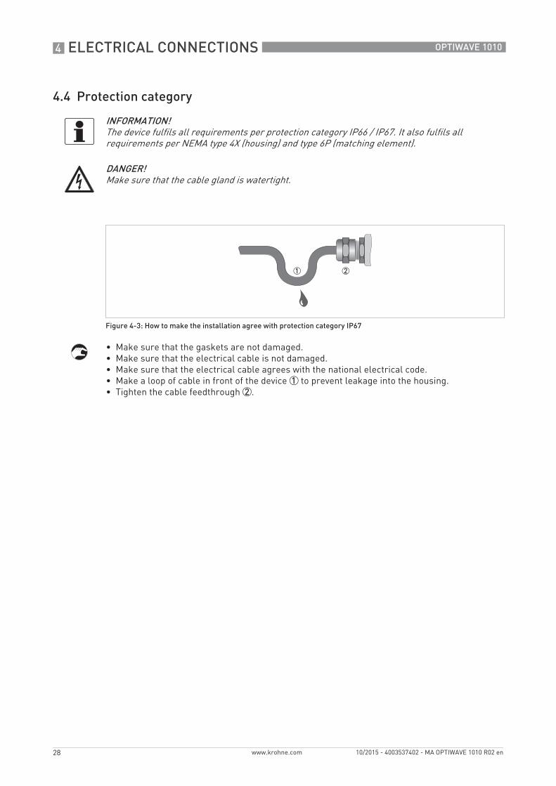
4.4 Protection category
• Make sure that the gaskets are not damaged.• Make sure that the electrical cable is not damaged.• Make sure that the electrical cable agrees with the national electrical code.• Make a loop of cable in front of the device 1 to prevent leakage into the housing.• Tighten the cable feedthrough 2.
INFORMATION!The device fulfils all requirements per protection category IP66 / IP67. It also fulfils all requirements per NEMA type 4X (housing) and type 6P (matching element).
DANGER!Make sure that the cable gland is watertight.
Figure 4-3: How to make the installation agree with protection category IP67
ELECTRICAL CONNECTIONS 4
29
OPTIWAVE 1010
www.krohne.com10/2015 - 4003537402 - MA OPTIWAVE 1010 R02 en
4.5 Networks
4.5.1 General information
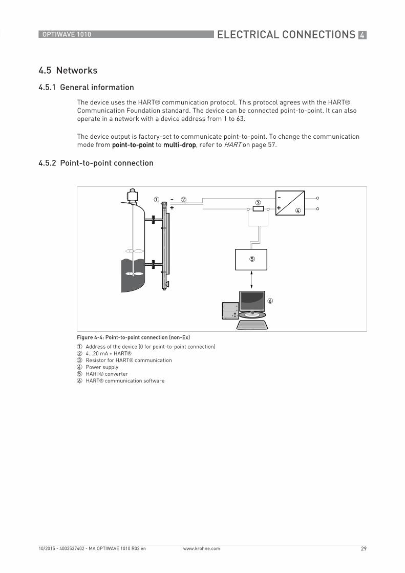
The device uses the HART® communication protocol. This protocol agrees with the HART® Communication Foundation standard. The device can be connected point-to-point. It can also operate in a network with a device address from 1 to 63.
The device output is factory-set to communicate point-to-point. To change the communication mode from point-to-pointpoint-to-pointpoint-to-pointpoint-to-point to multi-dropmulti-dropmulti-dropmulti-drop, refer to HART on page 57.
4.5.2 Point-to-point connection
Figure 4-4: Point-to-point connection (non-Ex)
1 Address of the device (0 for point-to-point connection)2 4...20 mA + HART®3 Resistor for HART® communication4 Power supply5 HART® converter6 HART® communication software
4 ELECTRICAL CONNECTIONS
30
OPTIWAVE 1010
www.krohne.com 10/2015 - 4003537402 - MA OPTIWAVE 1010 R02 en
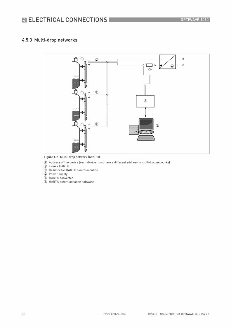
4.5.3 Multi-drop networks
Figure 4-5: Multi-drop network (non-Ex)
1 Address of the device (each device must have a different address in multidrop networks)2 4 mA + HART®3 Resistor for HART® communication4 Power supply5 HART® converter6 HART® communication software
START-UP 5
31
OPTIWAVE 1010
www.krohne.com10/2015 - 4003537402 - MA OPTIWAVE 1010 R02 en
5.1 How to start the device
5.1.1 Start-up checklist
Do a check of the device's condition before you energize the device:• Are all the wetted components (PEEK element, matching element and gaskets) resistant to
the product in the tank?• Does the information on the device nameplate agree with the operating data?• If the device is supplied with a magnetic (bypass) level indicator:If the device is supplied with a magnetic (bypass) level indicator:If the device is supplied with a magnetic (bypass) level indicator:If the device is supplied with a magnetic (bypass) level indicator: Did you correctly install the
magnetic level indicator adjacent to the tank?• If the device is supplied with a magnetic (bypass) level indicator:If the device is supplied with a magnetic (bypass) level indicator:If the device is supplied with a magnetic (bypass) level indicator:If the device is supplied with a magnetic (bypass) level indicator: Did you remove the float lock
pin from the side process connection at the bottom of the bypass chamber?• Do the electrical connections agree with the national electrical codes? Use the applicable
electrical cables with the cable glands.
5.1.2 How to start the device
• Connect the converter to the power supply.• Energize the converter.
5.2 Operating concept
You can read measurements and configure the device with:• A connection to a system or PC with PACTware™. You can download the Device Type
Manager (DTM) file from the website. It is also supplied on the DVD-ROM delivered with the device.
• A connection to a system or PC with AMS™. You can download the Device Description (DD) file from the website. It is also supplied on the DVD-ROM delivered with the device.
• A connection to a HART® Field Communicator. You can download the Device Description (DD) file from the website. It is also supplied on the DVD-ROM delivered with the device.
For more data about how to use the DTM in PACTware, refer to Operation on page 40. For more data about the menu tree for the Basic-DD, AMS and PDM, refer to Description of HART interface on page 76.
DANGER!Before you energize the device, make sure that the supply voltage is correct.
DANGER!Safe operation in hazardous locationsSafe operation in hazardous locationsSafe operation in hazardous locationsSafe operation in hazardous locationsMake sure that the installation and the wiring of the device agree with the related Ex standards and regulations. Make sure that the device has the applicable Ex approval for the hazardous location. For more data, refer to the related Ex certificate of conformity and the supplementary instructions.
INFORMATION!The manufacturer sets the parameters for your application in the factory. The 0% level (empty) is aligned with the center of the bottom process connection and the 100% level (full) is aligned with the center of the top process connection. You can use the HART communication protocol to change these parameters.
5 START-UP
32
OPTIWAVE 1010
www.krohne.com 10/2015 - 4003537402 - MA OPTIWAVE 1010 R02 en
5.3 Remote communication with PACTware™
5.3.1 General notes
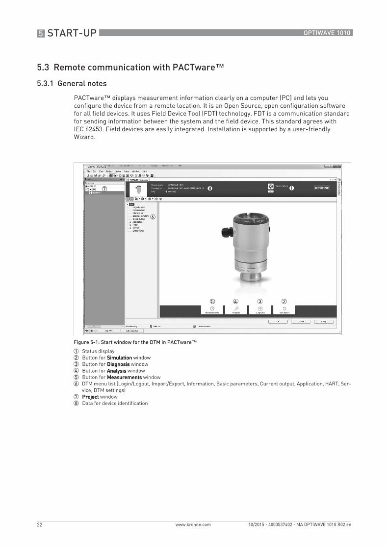
PACTware™ displays measurement information clearly on a computer (PC) and lets you configure the device from a remote location. It is an Open Source, open configuration software for all field devices. It uses Field Device Tool (FDT) technology. FDT is a communication standard for sending information between the system and the field device. This standard agrees with IEC 62453. Field devices are easily integrated. Installation is supported by a user-friendly Wizard.
Figure 5-1: Start window for the DTM in PACTware™
1 Status display2 Button for SimulationSimulationSimulationSimulation window3 Button for DiagnosisDiagnosisDiagnosisDiagnosis window4 Button for AnalysisAnalysisAnalysisAnalysis window5 Button for MeasurementsMeasurementsMeasurementsMeasurements window6 DTM menu list (Login/Logout, Import/Export, Information, Basic parameters, Current output, Application, HART, Ser-
vice, DTM settings)7 ProjectProjectProjectProject window8 Data for device identification
START-UP 5
33
OPTIWAVE 1010
www.krohne.com10/2015 - 4003537402 - MA OPTIWAVE 1010 R02 en
There are 4 buttons at the bottom of the StartStartStartStart window: MeasurementsMeasurementsMeasurementsMeasurements, AnalysisAnalysisAnalysisAnalysis, DiagnosisDiagnosisDiagnosisDiagnosis and SimulationSimulationSimulationSimulation. You can use these buttons to do the tasks that follow:
• Measurements: Measurements: Measurements: Measurements: Monitor level and distance data. For more data, refer to Measurements window on page 34.
• Analysis:Analysis:Analysis:Analysis: Monitor change and rate of change in level, distance, current output, temperature of the electronics and device status. It is also possible to monitor spectrum values. For more data, refer to Analysis window on page 35.
• Diagnosis: Diagnosis: Diagnosis: Diagnosis: Do a check of the device's condition (error messages etc.). For more data, refer to Diagnosis window on page 38.
• Simulation:Simulation:Simulation:Simulation: Simulate measured data to make sure that the device operates correctly. For more data, refer to Simulation window on page 39.
5.3.2 Software installation
Equipment needed• A computer• One of these two solutions: 1 the DVD-ROM delivered with the device or 2 a high-speed
Internet connection• A web browser, if it is necessary to download files from the Internet
Software needed• Microsoft® .NET Framework 2.0 or a later version• PACTware™ 4.1 or a later version• Device Type Manager (DTM) for the OPTIWAVE 1010 radar level transmitter
This software is supplied on the DVD-ROM delivered with the device. It can also be downloaded from the “Download center: Software” web page on the manufacturer’s website.
Installation procedure1 Install Microsoft® .NET Framework 2.0.2 Install PACTware™ 4.1 or later version.3 Install the OPTIWAVE 1010 DTM on your workstation or your portable computer. Follow the
instructions in the Installation wizard.4 Plug the HART modem into your computer (Serial or USB HART® modem). If you are using a
USB® HART modem, you must install the Driver for the USB HART® modem first. Make sure that the location of the port for the HART® modem is clearly identified.
5 Start the PACTware™ program.i End of the procedure.
5 START-UP
34
OPTIWAVE 1010
www.krohne.com 10/2015 - 4003537402 - MA OPTIWAVE 1010 R02 en
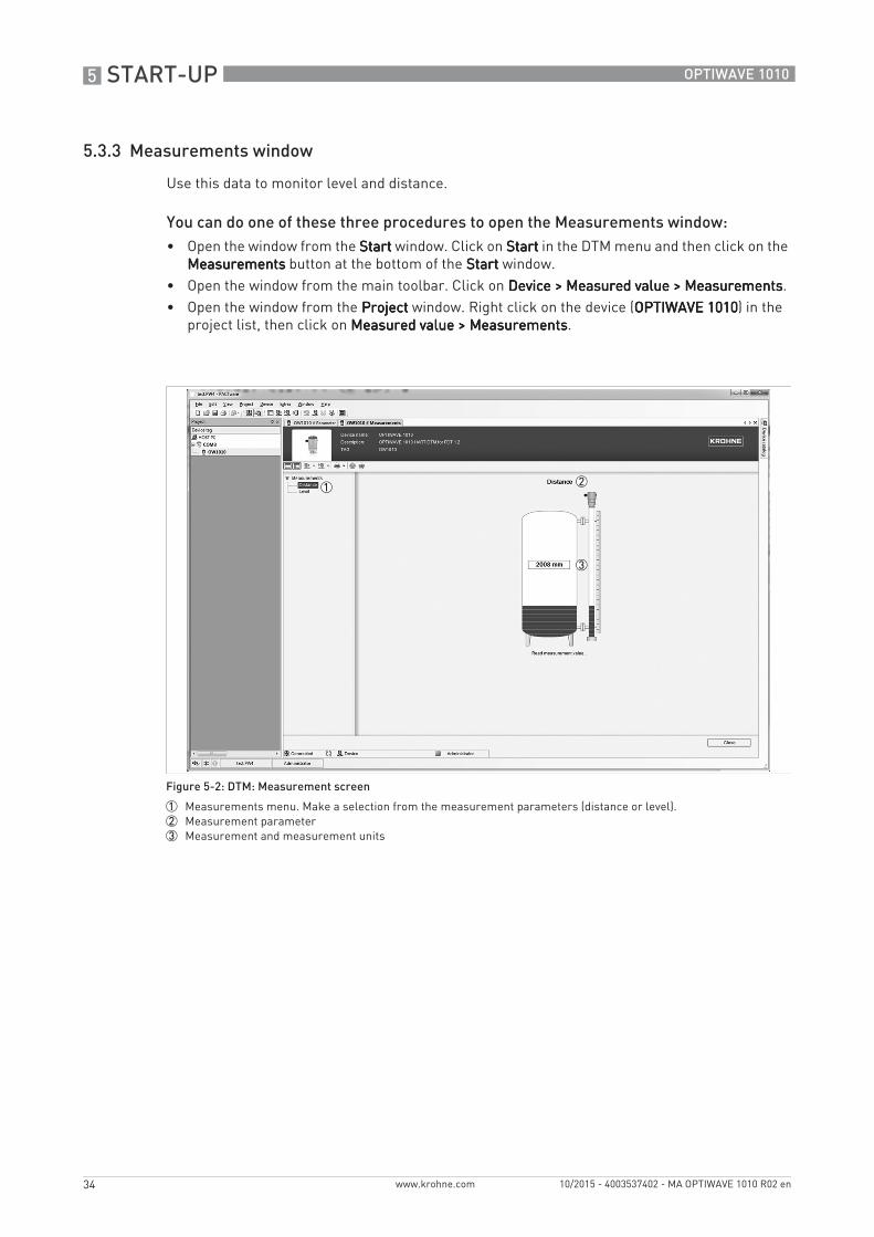
5.3.3 Measurements window
Use this data to monitor level and distance.
You can do one of these three procedures to open the Measurements window:• Open the window from the StartStartStartStart window. Click on StartStartStartStart in the DTM menu and then click on the
MeasurementsMeasurementsMeasurementsMeasurements button at the bottom of the StartStartStartStart window.• Open the window from the main toolbar. Click on Device > Measured value > MeasurementsDevice > Measured value > MeasurementsDevice > Measured value > MeasurementsDevice > Measured value > Measurements.• Open the window from the ProjectProjectProjectProject window. Right click on the device (OPTIWAVE 1010OPTIWAVE 1010OPTIWAVE 1010OPTIWAVE 1010) in the
project list, then click on Measured value > MeasurementsMeasured value > MeasurementsMeasured value > MeasurementsMeasured value > Measurements.
Figure 5-2: DTM: Measurement screen
1 Measurements menu. Make a selection from the measurement parameters (distance or level).2 Measurement parameter3 Measurement and measurement units
START-UP 5
35
OPTIWAVE 1010
www.krohne.com10/2015 - 4003537402 - MA OPTIWAVE 1010 R02 en
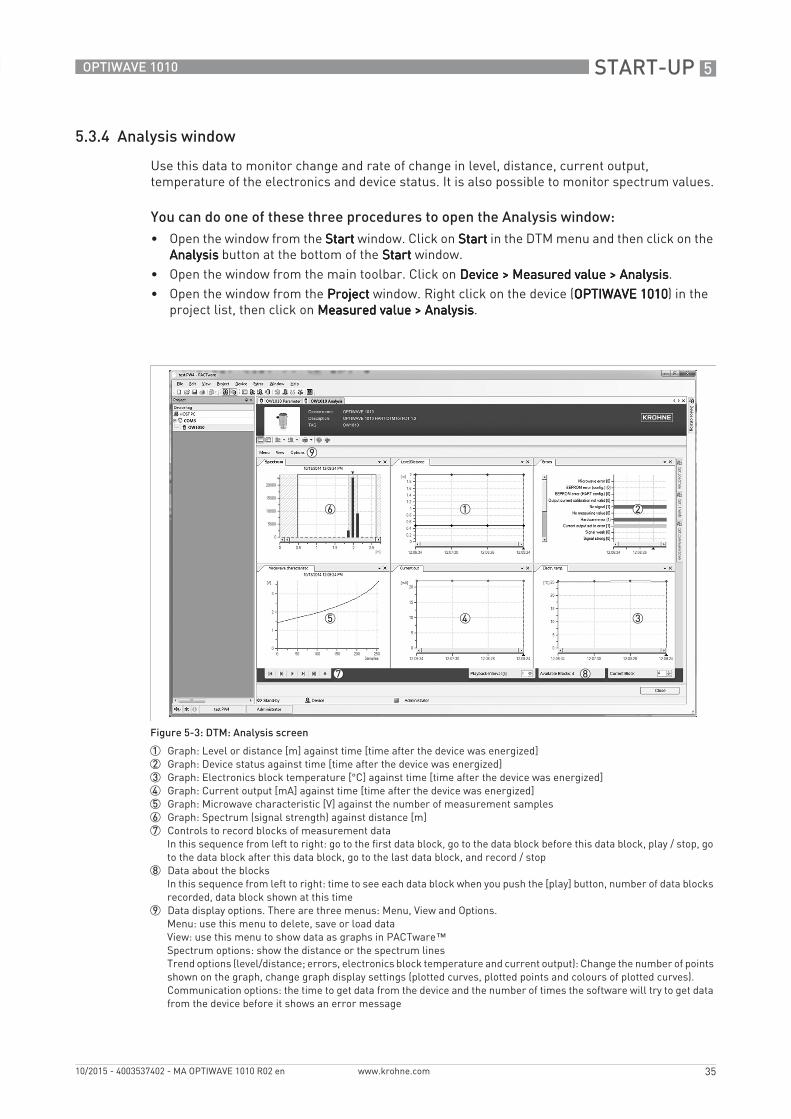
5.3.4 Analysis window
Use this data to monitor change and rate of change in level, distance, current output, temperature of the electronics and device status. It is also possible to monitor spectrum values.
You can do one of these three procedures to open the Analysis window:• Open the window from the StartStartStartStart window. Click on StartStartStartStart in the DTM menu and then click on the
AnalysisAnalysisAnalysisAnalysis button at the bottom of the StartStartStartStart window.• Open the window from the main toolbar. Click on Device > Measured value > AnalysisDevice > Measured value > AnalysisDevice > Measured value > AnalysisDevice > Measured value > Analysis.• Open the window from the ProjectProjectProjectProject window. Right click on the device (OPTIWAVE 1010OPTIWAVE 1010OPTIWAVE 1010OPTIWAVE 1010) in the
project list, then click on Measured value > AnalysisMeasured value > AnalysisMeasured value > AnalysisMeasured value > Analysis.
Figure 5-3: DTM: Analysis screen
1 Graph: Level or distance [m] against time [time after the device was energized]2 Graph: Device status against time [time after the device was energized]3 Graph: Electronics block temperature [°C] against time [time after the device was energized]4 Graph: Current output [mA] against time [time after the device was energized]5 Graph: Microwave characteristic [V] against the number of measurement samples6 Graph: Spectrum (signal strength) against distance [m]7 Controls to record blocks of measurement data
In this sequence from left to right: go to the first data block, go to the data block before this data block, play / stop, go to the data block after this data block, go to the last data block, and record / stop
8 Data about the blocksIn this sequence from left to right: time to see each data block when you push the [play] button, number of data blocks recorded, data block shown at this time
9 Data display options. There are three menus: Menu, View and Options.Menu: use this menu to delete, save or load dataView: use this menu to show data as graphs in PACTware™Spectrum options: show the distance or the spectrum linesTrend options (level/distance; errors, electronics block temperature and current output): Change the number of points shown on the graph, change graph display settings (plotted curves, plotted points and colours of plotted curves).Communication options: the time to get data from the device and the number of times the software will try to get data from the device before it shows an error message
5 START-UP
36
OPTIWAVE 1010
www.krohne.com 10/2015 - 4003537402 - MA OPTIWAVE 1010 R02 en
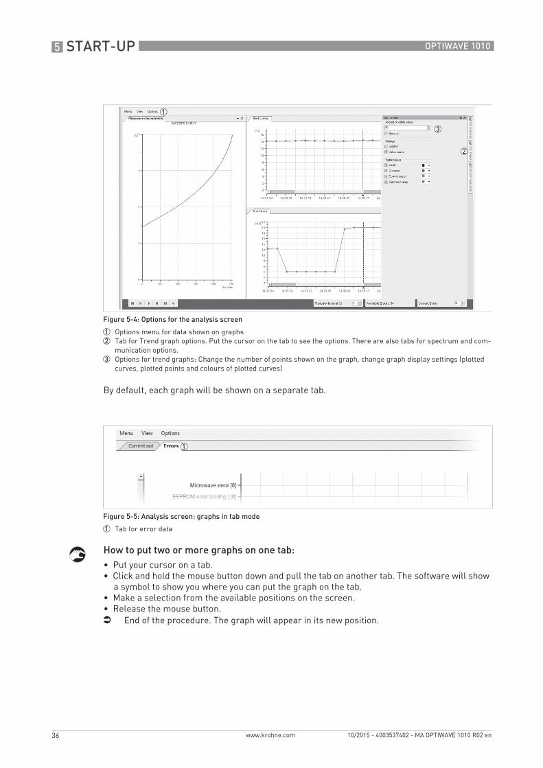
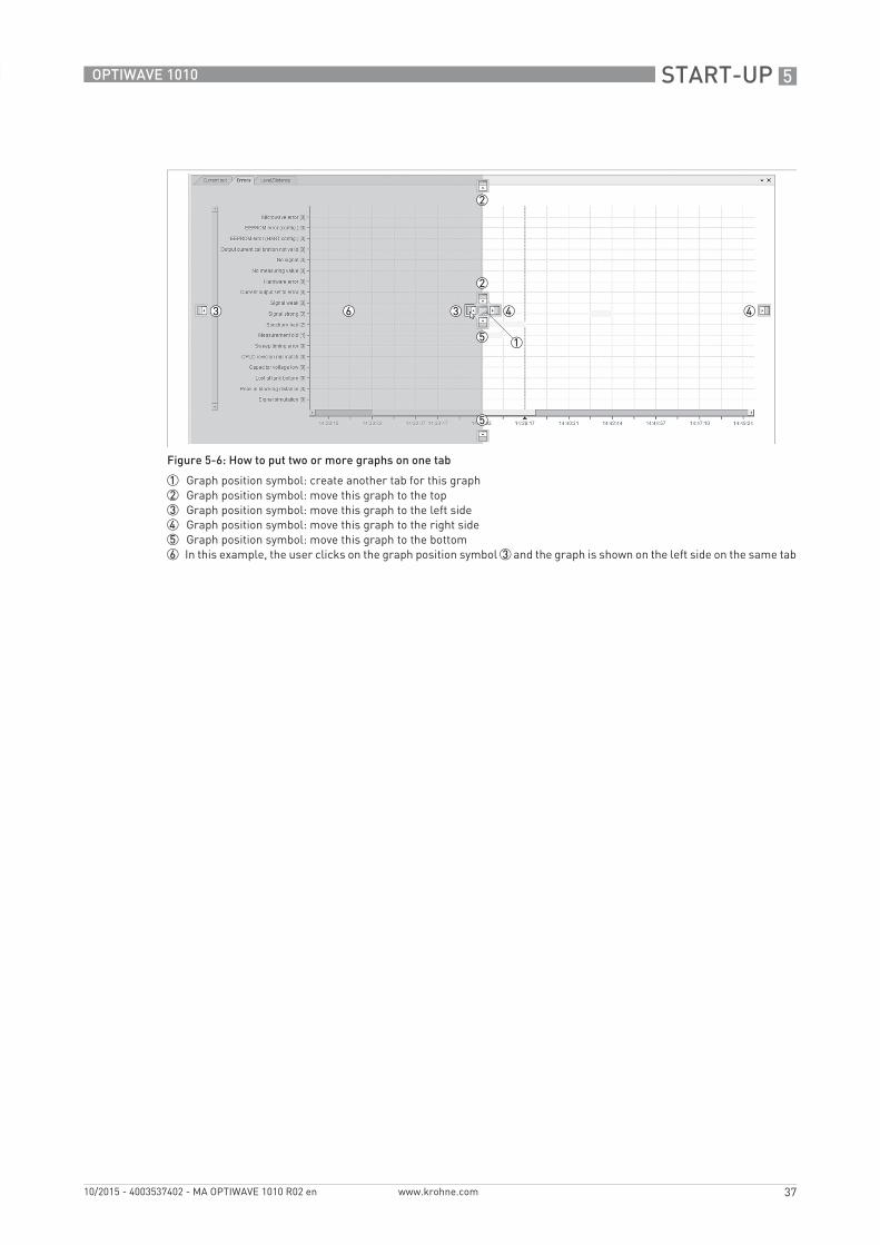
By default, each graph will be shown on a separate tab.
How to put two or more graphs on one tab:• Put your cursor on a tab.• Click and hold the mouse button down and pull the tab on another tab. The software will show
a symbol to show you where you can put the graph on the tab.• Make a selection from the available positions on the screen.• Release the mouse button.i End of the procedure. The graph will appear in its new position.
Figure 5-4: Options for the analysis screen
1 Options menu for data shown on graphs2 Tab for Trend graph options. Put the cursor on the tab to see the options. There are also tabs for spectrum and com-
munication options.3 Options for trend graphs: Change the number of points shown on the graph, change graph display settings (plotted
curves, plotted points and colours of plotted curves)
Figure 5-5: Analysis screen: graphs in tab mode
1 Tab for error data
START-UP 5
37
OPTIWAVE 1010
www.krohne.com10/2015 - 4003537402 - MA OPTIWAVE 1010 R02 en
Figure 5-6: How to put two or more graphs on one tab
1 Graph position symbol: create another tab for this graph2 Graph position symbol: move this graph to the top3 Graph position symbol: move this graph to the left side4 Graph position symbol: move this graph to the right side5 Graph position symbol: move this graph to the bottom6 In this example, the user clicks on the graph position symbol 3 and the graph is shown on the left side on the same tab
5 START-UP
38
OPTIWAVE 1010
www.krohne.com 10/2015 - 4003537402 - MA OPTIWAVE 1010 R02 en
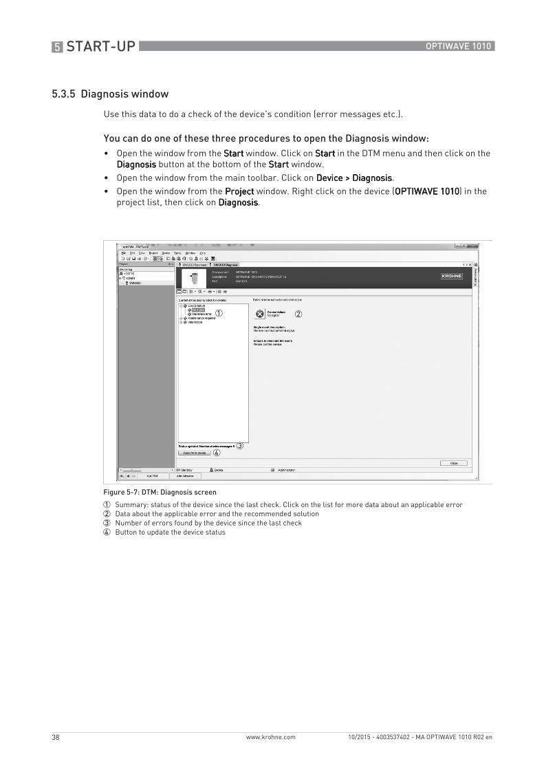
5.3.5 Diagnosis window
Use this data to do a check of the device's condition (error messages etc.).
You can do one of these three procedures to open the Diagnosis window:• Open the window from the StartStartStartStart window. Click on StartStartStartStart in the DTM menu and then click on the
DiagnosisDiagnosisDiagnosisDiagnosis button at the bottom of the StartStartStartStart window.• Open the window from the main toolbar. Click on Device > DiagnosisDevice > DiagnosisDevice > DiagnosisDevice > Diagnosis.• Open the window from the ProjectProjectProjectProject window. Right click on the device (OPTIWAVE 1010OPTIWAVE 1010OPTIWAVE 1010OPTIWAVE 1010) in the
project list, then click on DiagnosisDiagnosisDiagnosisDiagnosis.
Figure 5-7: DTM: Diagnosis screen
1 Summary: status of the device since the last check. Click on the list for more data about an applicable error2 Data about the applicable error and the recommended solution3 Number of errors found by the device since the last check4 Button to update the device status
START-UP 5
39
OPTIWAVE 1010
www.krohne.com10/2015 - 4003537402 - MA OPTIWAVE 1010 R02 en
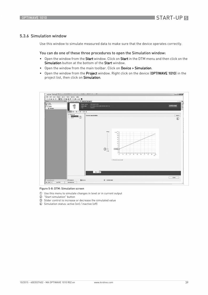
5.3.6 Simulation window
Use this window to simulate measured data to make sure that the device operates correctly.
You can do one of these three procedures to open the Simulation window:• Open the window from the StartStartStartStart window. Click on StartStartStartStart in the DTM menu and then click on the
SimulationSimulationSimulationSimulation button at the bottom of the StartStartStartStart window.• Open the window from the main toolbar. Click on Device > SimulationDevice > SimulationDevice > SimulationDevice > Simulation.• Open the window from the ProjectProjectProjectProject window. Right click on the device (OPTIWAVE 1010OPTIWAVE 1010OPTIWAVE 1010OPTIWAVE 1010) in the
project list, then click on SimulationSimulationSimulationSimulation.
Figure 5-8: DTM: Simulation screen
1 Use this menu to simulate changes in level or in current output2 "Start simulation" button3 Slider control to increase or decrease the simulated value4 Simulation status: active (on) / inactive (off)
6 OPERATION
40
OPTIWAVE 1010
www.krohne.com 10/2015 - 4003537402 - MA OPTIWAVE 1010 R02 en
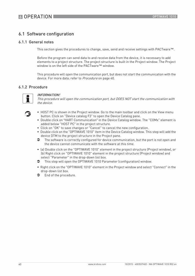
6.1 Software configuration
6.1.1 General notes
This section gives the procedures to change, save, send and receive settings with PACTware™.
Before the program can send data to and receive data from the device, it is necessary to add elements to a project structure. The project structure is built in the Project window. The Project window is on the left side of the PACTware™ window.
This procedure will open the communication port, but does not start the communication with the device. For more data; refer to Procedure on page 40.
6.1.2 Procedure
• HOST PC is shown in the Project window. Go to the main toolbar and click on the View menu button. Click on "Device catalog F3" to open the Device Catalog pane.
• Double click on “HART Communication” in the Device Catalog window. The "COMx" element is added below "HOST PC” in the project structure.
• Click on "OK" to save changes or "Cancel" to cancel the new configuration.• Double click on the "OPTIWAVE 1010" item in the Device Catalog window. This step will add the
device DTM to the project structure in the Project pane.i The software is correctly configured for device communication, but the port is not open and
the device cannot communicate with the software at this time.
• (a) Double click on the "OPTIWAVE 1010" element in the project structure (Project window), or (b) Right click on "OPTIWAVE 1010" element in the project structure (Project window) and select "Parameter" in the drop-down list box.
i This step will open the OPTIWAVE 1010 Parameter (configuration) window.
• Right click on the "OPTIWAVE 1010" element in the Project window and select "Connect" in the drop-down list box.
i End of the procedure.
INFORMATION!This procedure will open the communication port, but DOES NOT start the communication with the device.
OPERATION 6
41
OPTIWAVE 1010
www.krohne.com10/2015 - 4003537402 - MA OPTIWAVE 1010 R02 en
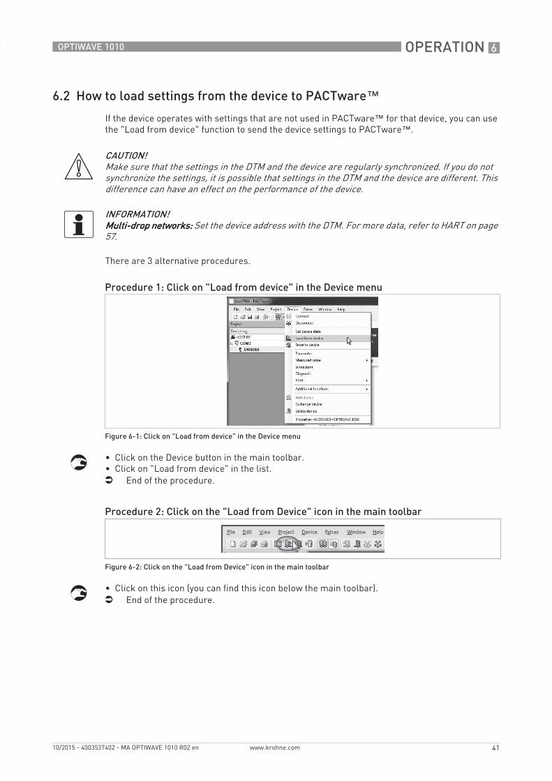
6.2 How to load settings from the device to PACTware™If the device operates with settings that are not used in PACTware™ for that device, you can use the "Load from device" function to send the device settings to PACTware™.
There are 3 alternative procedures.
• Click on the Device button in the main toolbar.• Click on "Load from device" in the list.i End of the procedure.
• Click on this icon (you can find this icon below the main toolbar).i End of the procedure.
CAUTION!Make sure that the settings in the DTM and the device are regularly synchronized. If you do not synchronize the settings, it is possible that settings in the DTM and the device are different. This difference can have an effect on the performance of the device.
INFORMATION!Multi-drop networks:Multi-drop networks:Multi-drop networks:Multi-drop networks: Set the device address with the DTM. For more data, refer to HART on page 57.
Procedure 1: Click on "Load from device" in the Device menu
Figure 6-1: Click on "Load from device" in the Device menu
Procedure 2: Click on the "Load from Device" icon in the main toolbar
Figure 6-2: Click on the "Load from Device" icon in the main toolbar
6 OPERATION
42
OPTIWAVE 1010
www.krohne.com 10/2015 - 4003537402 - MA OPTIWAVE 1010 R02 en
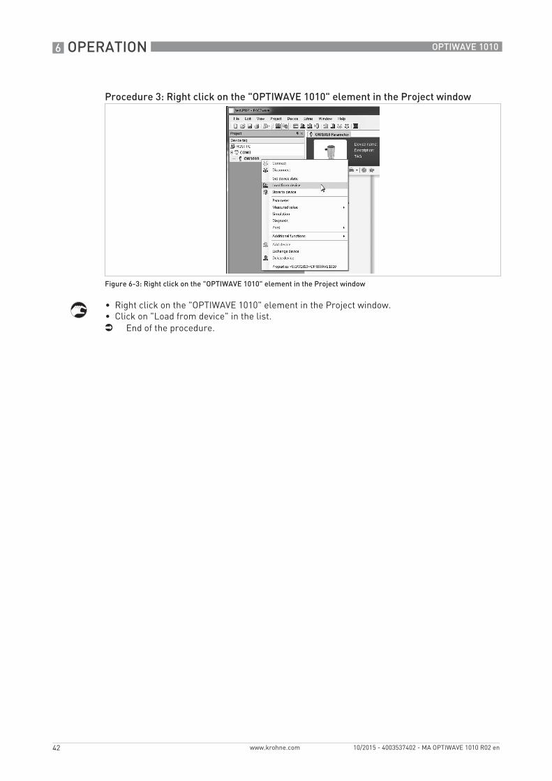
• Right click on the "OPTIWAVE 1010" element in the Project window.• Click on "Load from device" in the list.i End of the procedure.
Procedure 3: Right click on the "OPTIWAVE 1010" element in the Project window
Figure 6-3: Right click on the "OPTIWAVE 1010" element in the Project window
OPERATION 6
43
OPTIWAVE 1010
www.krohne.com10/2015 - 4003537402 - MA OPTIWAVE 1010 R02 en
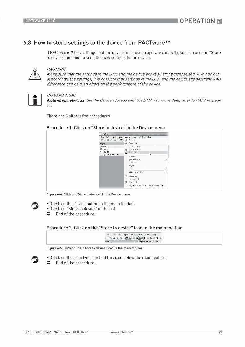
6.3 How to store settings to the device from PACTware™If PACTware™ has settings that the device must use to operate correctly, you can use the "Store to device" function to send the new settings to the device.
There are 3 alternative procedures.
• Click on the Device button in the main toolbar.• Click on "Store to device" in the list.i End of the procedure.
• Click on this icon (you can find this icon below the main toolbar).i End of the procedure.
CAUTION!Make sure that the settings in the DTM and the device are regularly synchronized. If you do not synchronize the settings, it is possible that settings in the DTM and the device are different. This difference can have an effect on the performance of the device.
INFORMATION!Multi-drop networks:Multi-drop networks:Multi-drop networks:Multi-drop networks: Set the device address with the DTM. For more data, refer to HART on page 57.
Procedure 1: Click on "Store to device" in the Device menu
Figure 6-4: Click on "Store to device" in the Device menu
Procedure 2: Click on the "Store to device" icon in the main toolbar
Figure 6-5: Click on the "Store to device" icon in the main toolbar
6 OPERATION
44
OPTIWAVE 1010
www.krohne.com 10/2015 - 4003537402 - MA OPTIWAVE 1010 R02 en
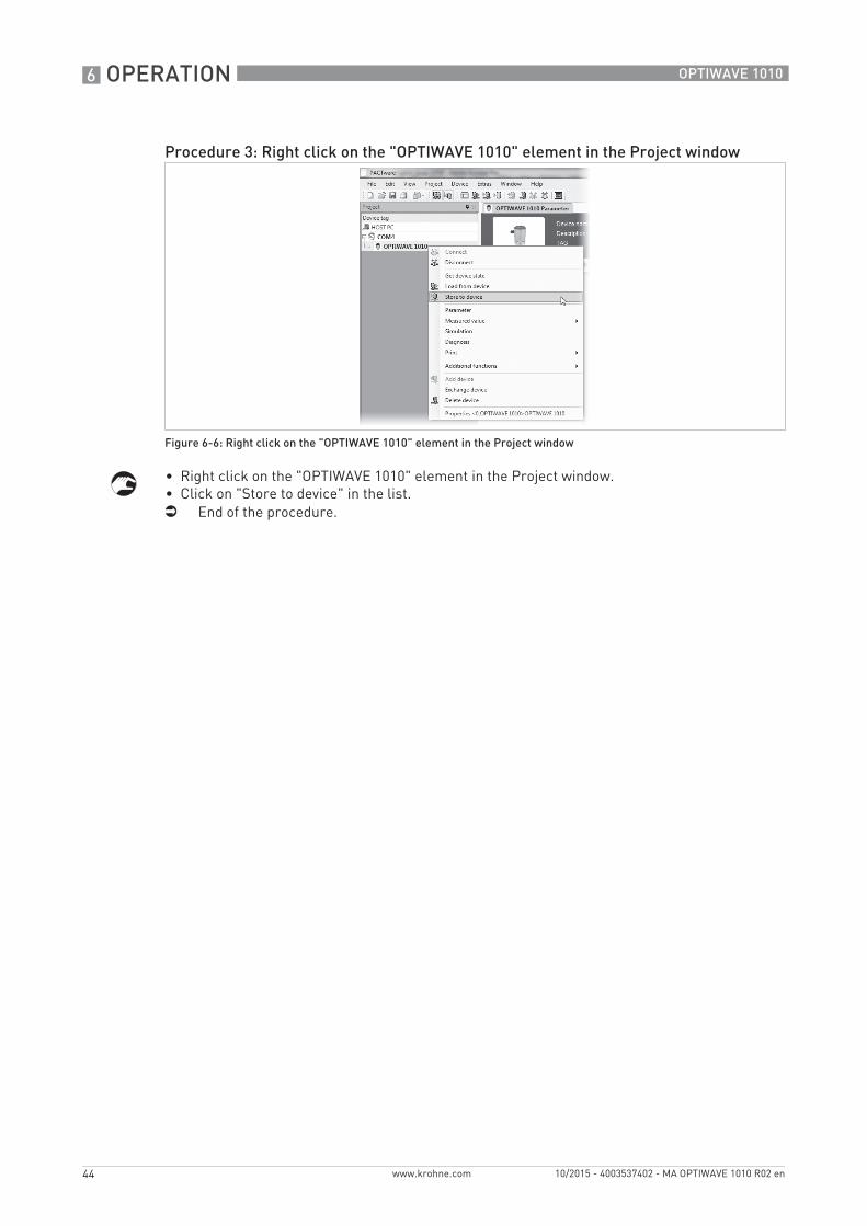
• Right click on the "OPTIWAVE 1010" element in the Project window.• Click on "Store to device" in the list.i End of the procedure.
Procedure 3: Right click on the "OPTIWAVE 1010" element in the Project window
Figure 6-6: Right click on the "OPTIWAVE 1010" element in the Project window
OPERATION 6
45
OPTIWAVE 1010
www.krohne.com10/2015 - 4003537402 - MA OPTIWAVE 1010 R02 en
6.4 Menu overview
Login/LogoutLogin/LogoutLogin/LogoutLogin/Logout It is necessary to use a password in this menu. Give a 6-digit code. This menu permits the supervisor to set and lock device settings that are available to the supervisor and change the supervisor password. The default password is 123412123412123412123412.
This menu also permits personnel approved by the manufacturer to change device settings in the service menu.
Import/ExportImport/ExportImport/ExportImport/Export You can save all device settings to a workstation (Parameter menus: export). This data can then be used to reset the device to its initial settings if an unwanted change is made. If you want to operate other devices with the same settings, you can also load this data into other devices (Parameter menus: import).
You can also save measurement data in a .DAT file to a workstation.
InformationInformationInformationInformation Read only. This menu gives data about the version of the hardware and software, the device serial number and the customer order number.
Basic parametersBasic parametersBasic parametersBasic parameters The device must be attached to a bypass chamber to operate correctly. The manufacturer usually sets the values for the minimum distance, the maximum distance, the float offset and the internal diameter of the tube in the factory.
If the device does not have the correct settings in this menu, then these values can have an effect on the performance of the device. If you make an incorrect selection of the float, go to Application > Float offset calculationApplication > Float offset calculationApplication > Float offset calculationApplication > Float offset calculation in the DTM menu to calculate the new float offset value.
Current outputCurrent outputCurrent outputCurrent output You can make a selection from the parameters in the output function, output current range and error delay lists.
ApplicationApplicationApplicationApplication Use this menu to change how the device operates when there are difficult process conditions. Only approved personnel can change these parameters. The supervisor can give the time constant, maximum tracing speed and multiple reflections to identify the correct signal and follow it as level changes.
Float offset calculationFloat offset calculationFloat offset calculationFloat offset calculation If the device does not have the correct float in the bypass chamber, then the float offset value in the Basic Basic Basic Basic parametersparametersparametersparameters menu is incorrect. An incorrect float offset value can have an effect on the measurement data. Go to Application > Float offset calculationApplication > Float offset calculationApplication > Float offset calculationApplication > Float offset calculation in the DTM menu to calculate the new float offset value. Follow the procedure.
HARTHARTHARTHART Use this menu to change the tag name and read data (Device ID, Field device revision etc.) that agrees with the HART® specification. You can also change the units of the measured values.
ServiceServiceServiceService This menu contains advanced device settings. It is locked with a password. The handbook does not include data about the service menu.
DTM settingsDTM settingsDTM settingsDTM settings Use this menu to change how the status display shows data at the top of the DTM window.

6 OPERATION
46
OPTIWAVE 1010
www.krohne.com 10/2015 - 4003537402 - MA OPTIWAVE 1010 R02 en
6.5 How to change device settings
At the bottom right of the window there are 3 buttons. This function obeys FDT guidelines for certification of the DTM.
When you change the value or parameter of a menu item, a pencil symbol is shown adjacent to the changed value:
If the value is too large or too small, a red exclamation mark is shown adjacent to the incorrect value:
CAUTION!If you change the device settings, the DTM saves this data in the workstation. It does not send the changes to the device. For more data about how to send changes to the device, refer to How to store settings to the device from PACTware™ on page 43.
Figure 6-7: "OK" or "Apply" updates the device settings data in the computer
Figure 6-8: Pencil symbol: changed value
Figure 6-9: Exclamation mark (!): the value is too large or too small
OPERATION 6
47
OPTIWAVE 1010
www.krohne.com10/2015 - 4003537402 - MA OPTIWAVE 1010 R02 en
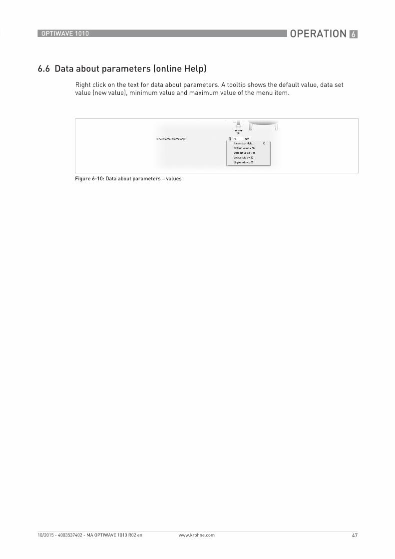
6.6 Data about parameters (online Help)
Right click on the text for data about parameters. A tooltip shows the default value, data set value (new value), minimum value and maximum value of the menu item.
Figure 6-10: Data about parameters – values
6 OPERATION
48
OPTIWAVE 1010
www.krohne.com 10/2015 - 4003537402 - MA OPTIWAVE 1010 R02 en
6.7 Device settings
6.7.1 Password protection for device settings
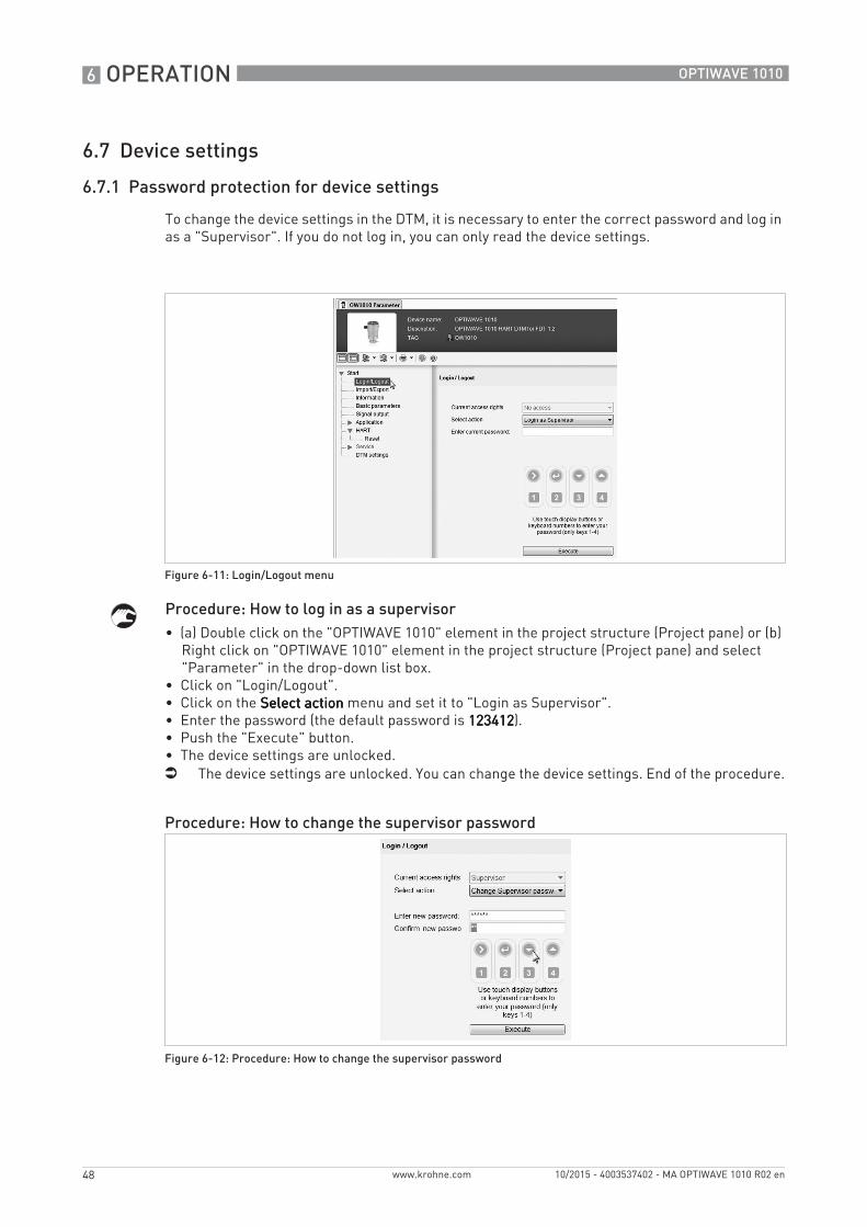
To change the device settings in the DTM, it is necessary to enter the correct password and log in as a "Supervisor". If you do not log in, you can only read the device settings.
Procedure: How to log in as a supervisor• (a) Double click on the "OPTIWAVE 1010" element in the project structure (Project pane) or (b)
Right click on "OPTIWAVE 1010" element in the project structure (Project pane) and select "Parameter" in the drop-down list box.
• Click on "Login/Logout".• Click on the Select actionSelect actionSelect actionSelect action menu and set it to "Login as Supervisor".• Enter the password (the default password is 123412123412123412123412).• Push the "Execute" button.• The device settings are unlocked.i The device settings are unlocked. You can change the device settings. End of the procedure.
Figure 6-11: Login/Logout menu
Procedure: How to change the supervisor password
Figure 6-12: Procedure: How to change the supervisor password
OPERATION 6
49
OPTIWAVE 1010
www.krohne.com10/2015 - 4003537402 - MA OPTIWAVE 1010 R02 en
• (a) Double click on the "OPTIWAVE 1010" element in the project structure (Project pane) or (b) Right click on "OPTIWAVE 1010" element in the project structure (Project pane) and select "Parameter" in the drop-down list box.
• Click on "Login/Logout".• Click on the Select actionSelect actionSelect actionSelect action menu and set it to "Change supervisor password".• Use the [>>>>], [^̂̂̂], [ ] and [ ] buttons on the DTM window or the [1111], [2222], [3333] and [4444] buttons on
the computer keyboard to enter the new 6-digit password.• Enter the new 6-digit password again.• Push the "Execute" button.i You changed the password. End of the procedure.
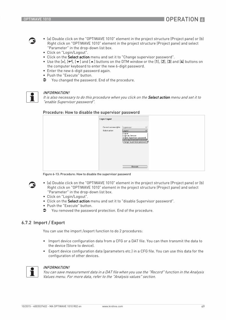
• (a) Double click on the "OPTIWAVE 1010" element in the project structure (Project pane) or (b) Right click on "OPTIWAVE 1010" element in the project structure (Project pane) and select "Parameter" in the drop-down list box.
• Click on "Login/Logout".• Click on the Select actionSelect actionSelect actionSelect action menu and set it to "disable Supervisor password".• Push the "Execute" button.i You removed the password protection. End of the procedure.
6.7.2 Import / Export
You can use the import /export function to do 2 procedures:
• Import device configuration data from a CFG or a DAT file. You can then transmit the data to the device (Store to device).
• Export device configuration data (parameters etc.) in a CFG file. You can use this data for the configuration of other devices.
INFORMATION!It is also necessary to do this procedure when you click on the Select actionSelect actionSelect actionSelect action menu and set it to "enable Supervisor password".
Procedure: How to disable the supervisor password
Figure 6-13: Procedure: How to disable the supervisor password
INFORMATION!You can save measurement data in a DAT file when you use the "Record" function in the Analysis Values menu. For more data, refer to the "Analysis values" section.
6 OPERATION
50
OPTIWAVE 1010
www.krohne.com 10/2015 - 4003537402 - MA OPTIWAVE 1010 R02 en
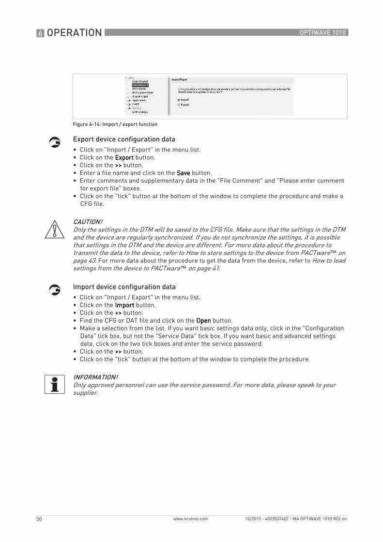
Export device configuration data• Click on "Import / Export" in the menu list.• Click on the ExportExportExportExport button.• Click on the >>>>>>>> button.• Enter a file name and click on the SaveSaveSaveSave button.• Enter comments and supplementary data in the "File Comment" and "Please enter comment
for export file" boxes.• Click on the "tick" button at the bottom of the window to complete the procedure and make a
CFG file.
Import device configuration data• Click on "Import / Export" in the menu list.• Click on the ImportImportImportImport button.• Click on the >>>>>>>> button.• Find the CFG or DAT file and click on the OpenOpenOpenOpen button.• Make a selection from the list. If you want basic settings data only, click in the "Configuration
Data" tick box, but not the "Service Data" tick box. If you want basic and advanced settings data, click on the two tick boxes and enter the service password.
• Click on the >>>>>>>> button.• Click on the "tick" button at the bottom of the window to complete the procedure.
Figure 6-14: Import / export function
CAUTION!Only the settings in the DTM will be saved to the CFG file. Make sure that the settings in the DTM and the device are regularly synchronized. If you do not synchronize the settings, it is possible that settings in the DTM and the device are different. For more data about the procedure to transmit the data to the device, refer to How to store settings to the device from PACTware™ on page 43. For more data about the procedure to get the data from the device, refer to How to load settings from the device to PACTware™ on page 41.
INFORMATION!Only approved personnel can use the service password. For more data, please speak to your supplier.
OPERATION 6
51
OPTIWAVE 1010
www.krohne.com10/2015 - 4003537402 - MA OPTIWAVE 1010 R02 en
6.7.3 Information
This is a read only menu that gives data in the list that follows:
• Firmware version• Configuration changed counter• Software revision• Hardware revision• Complete device serial number• Electronic serial number• Electronics and housing serial number• Sales order number
6 OPERATION
52
OPTIWAVE 1010
www.krohne.com 10/2015 - 4003537402 - MA OPTIWAVE 1010 R02 en
6.7.4 Basic parameters
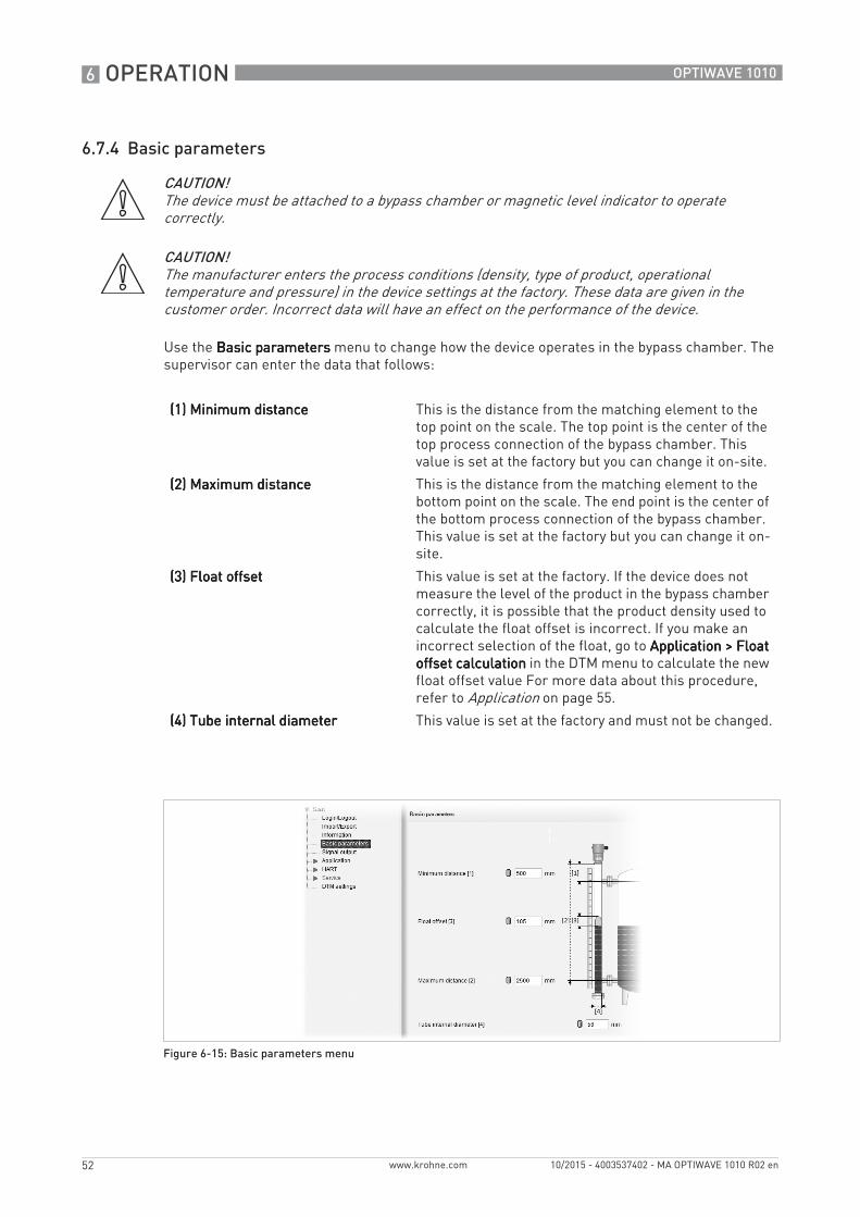
Use the Basic parametersBasic parametersBasic parametersBasic parameters menu to change how the device operates in the bypass chamber. The supervisor can enter the data that follows:
CAUTION!The device must be attached to a bypass chamber or magnetic level indicator to operate correctly.
CAUTION!The manufacturer enters the process conditions (density, type of product, operational temperature and pressure) in the device settings at the factory. These data are given in the customer order. Incorrect data will have an effect on the performance of the device.
(1) Minimum distance(1) Minimum distance(1) Minimum distance(1) Minimum distance This is the distance from the matching element to the top point on the scale. The top point is the center of the top process connection of the bypass chamber. This value is set at the factory but you can change it on-site.
(2) Maximum distance(2) Maximum distance(2) Maximum distance(2) Maximum distance This is the distance from the matching element to the bottom point on the scale. The end point is the center of the bottom process connection of the bypass chamber. This value is set at the factory but you can change it on-site.
(3) Float offset(3) Float offset(3) Float offset(3) Float offset This value is set at the factory. If the device does not measure the level of the product in the bypass chamber correctly, it is possible that the product density used to calculate the float offset is incorrect. If you make an incorrect selection of the float, go to Application > Float Application > Float Application > Float Application > Float offset calculationoffset calculationoffset calculationoffset calculation in the DTM menu to calculate the new float offset value For more data about this procedure, refer to Application on page 55.
(4) Tube internal diameter(4) Tube internal diameter(4) Tube internal diameter(4) Tube internal diameter This value is set at the factory and must not be changed.
Figure 6-15: Basic parameters menu
OPERATION 6
53
OPTIWAVE 1010
www.krohne.com10/2015 - 4003537402 - MA OPTIWAVE 1010 R02 en
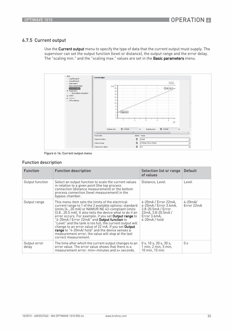
6.7.5 Current output
Use the Current outputCurrent outputCurrent outputCurrent output menu to specify the type of data that the current output must supply. The supervisor can set the output function (level or distance), the output range and the error delay. The "scaling min." and the "scaling max." values are set in the Basic parametersBasic parametersBasic parametersBasic parameters menu.
Function description
Figure 6-16: Current output menu
Function Function description Selection list or range of values
Default
Output function Select an output function to scale the current values in relation to a given point (the top process connection (distance measurement) or the bottom process connection (level measurement) in the bypass chamber.
Distance, Level Level
Output range This menu item sets the limits of the electrical current range to 1 of the 2 available options: standard limits (4...20 mA) or NAMUR NE 43-compliant limits (3.8...20.5 mA). It also tells the device what to do if an error occurs. For example, if you set Output rangeOutput rangeOutput rangeOutput range to "4-20mA / Error 22mA" and Output functionOutput functionOutput functionOutput function to "Level" and the tank is too full, the current output will change to an error value of 22 mA. If you set Output Output Output Output rangerangerangerange to "4-20mA/ hold" and the device senses a measurement error, the value will stop at the last correct measurement.
4-20mA / Error 22mA, 4-20mA / Error 3.6mA, 3.8-20.5mA / Error 22mA, 3.8-20.5mA / Error 3.6mA, 4-20mA / hold
4-20mA/ Error 22mA
Output error delay
The time after which the current output changes to an error value. The error value shows that there is a measurement error. min= minutes and s= seconds.
0 s, 10 s, 20 s, 30 s, 1 min, 2 min, 5 min, 10 min, 15 min
0 s
6 OPERATION
54
OPTIWAVE 1010
www.krohne.com 10/2015 - 4003537402 - MA OPTIWAVE 1010 R02 en
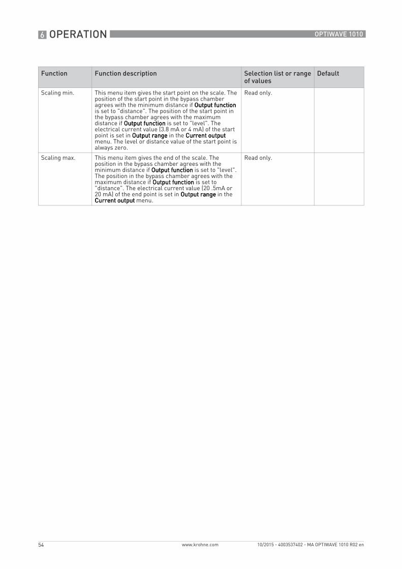
Scaling min. This menu item gives the start point on the scale. The position of the start point in the bypass chamber agrees with the minimum distance if Output functionOutput functionOutput functionOutput function is set to "distance". The position of the start point in the bypass chamber agrees with the maximum distance if Output functionOutput functionOutput functionOutput function is set to "level". The electrical current value (3.8 mA or 4 mA) of the start point is set in Output rangeOutput rangeOutput rangeOutput range in the Current output Current output Current output Current output menu. The level or distance value of the start point is always zero.
Read only.
Scaling max. This menu item gives the end of the scale. The position in the bypass chamber agrees with the minimum distance if Output functionOutput functionOutput functionOutput function is set to "level". The position in the bypass chamber agrees with the maximum distance if Output functionOutput functionOutput functionOutput function is set to "distance". The electrical current value (20 .5mA or 20 mA) of the end point is set in Output rangeOutput rangeOutput rangeOutput range in the Current outputCurrent outputCurrent outputCurrent output menu.
Read only.
Function Function description Selection list or range of values
Default
OPERATION 6
55
OPTIWAVE 1010
www.krohne.com10/2015 - 4003537402 - MA OPTIWAVE 1010 R02 en
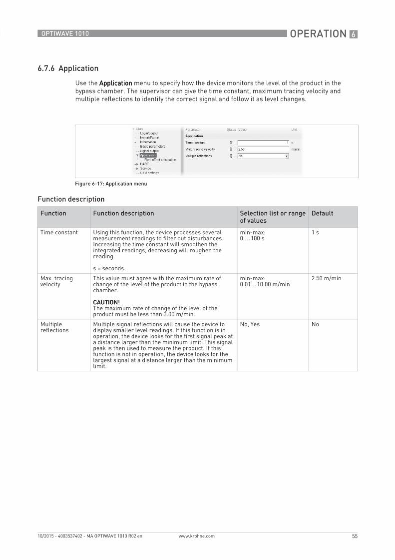
6.7.6 Application
Use the ApplicationApplicationApplicationApplication menu to specify how the device monitors the level of the product in the bypass chamber. The supervisor can give the time constant, maximum tracing velocity and multiple reflections to identify the correct signal and follow it as level changes.
Function description
Figure 6-17: Application menu
Function Function description Selection list or range of values
Default
Time constant Using this function, the device processes several measurement readings to filter out disturbances. Increasing the time constant will smoothen the integrated readings, decreasing will roughen the reading.
s = seconds.
min-max:0.…100 s
1 s
Max. tracing velocity
This value must agree with the maximum rate of change of the level of the product in the bypass chamber.
CAUTION!CAUTION!CAUTION!CAUTION!The maximum rate of change of the level of the product must be less than 3.00 m/min.
min-max:0.01…10.00 m/min
2.50 m/min
Multiple reflections
Multiple signal reflections will cause the device to display smaller level readings. If this function is in operation, the device looks for the first signal peak at a distance larger than the minimum limit. This signal peak is then used to measure the product. If this function is not in operation, the device looks for the largest signal at a distance larger than the minimum limit.
No, Yes No
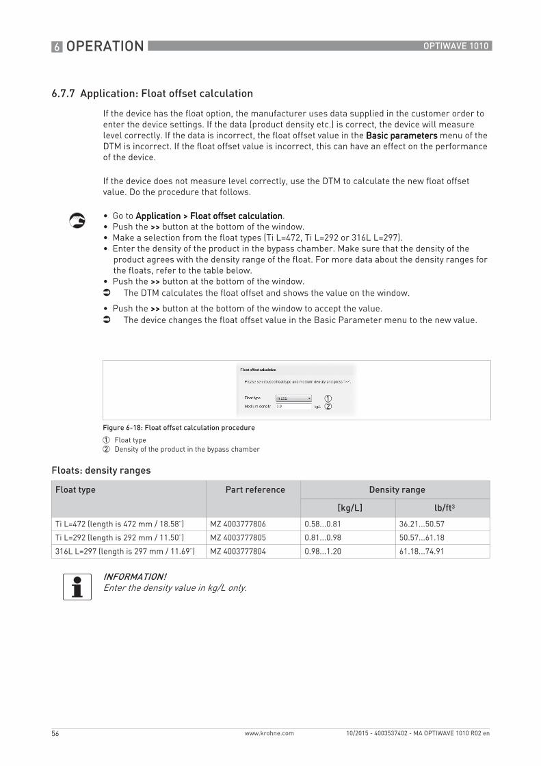
6 OPERATION
56
OPTIWAVE 1010
www.krohne.com 10/2015 - 4003537402 - MA OPTIWAVE 1010 R02 en
6.7.7 Application: Float offset calculation
If the device has the float option, the manufacturer uses data supplied in the customer order to enter the device settings. If the data (product density etc.) is correct, the device will measure level correctly. If the data is incorrect, the float offset value in the Basic parametersBasic parametersBasic parametersBasic parameters menu of the DTM is incorrect. If the float offset value is incorrect, this can have an effect on the performance of the device.
If the device does not measure level correctly, use the DTM to calculate the new float offset value. Do the procedure that follows.
• Go to Application > Float offset calculationApplication > Float offset calculationApplication > Float offset calculationApplication > Float offset calculation.• Push the >>>>>>>> button at the bottom of the window.• Make a selection from the float types (Ti L=472, Ti L=292 or 316L L=297).• Enter the density of the product in the bypass chamber. Make sure that the density of the
product agrees with the density range of the float. For more data about the density ranges for the floats, refer to the table below.
• Push the >>>>>>>> button at the bottom of the window.i The DTM calculates the float offset and shows the value on the window.
• Push the >>>>>>>> button at the bottom of the window to accept the value.i The device changes the float offset value in the Basic Parameter menu to the new value.
Floats: density ranges
Figure 6-18: Float offset calculation procedure
1 Float type2 Density of the product in the bypass chamber
Float type Part reference Density range
[kg/L] lb/ft³
Ti L=472 (length is 472 mm / 18.58¨) MZ 4003777806 0.58...0.81 36.21...50.57
Ti L=292 (length is 292 mm / 11.50¨) MZ 4003777805 0.81...0.98 50.57...61.18
316L L=297 (length is 297 mm / 11.69¨) MZ 4003777804 0.98...1.20 61.18...74.91
INFORMATION!Enter the density value in kg/L only.
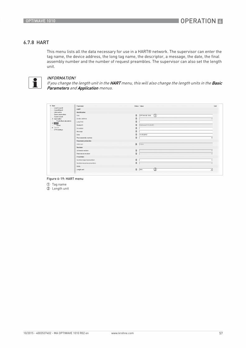
OPERATION 6
57
OPTIWAVE 1010
www.krohne.com10/2015 - 4003537402 - MA OPTIWAVE 1010 R02 en
6.7.8 HART
This menu lists all the data necessary for use in a HART® network. The supervisor can enter the tag name, the device address, the long tag name, the descriptor, a message, the date, the final assembly number and the number of request preambles. The supervisor can also set the length unit.
INFORMATION!If you change the length unit in the HARTHARTHARTHART menu, this will also change the length units in the Basic Basic Basic Basic ParametersParametersParametersParameters and ApplicationApplicationApplicationApplication menus.
Figure 6-19: HART menu
1 Tag name2 Length unit
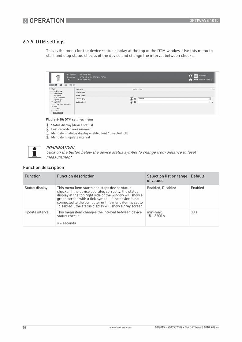
6 OPERATION
58
OPTIWAVE 1010
www.krohne.com 10/2015 - 4003537402 - MA OPTIWAVE 1010 R02 en
6.7.9 DTM settings
This is the menu for the device status display at the top of the DTM window. Use this menu to start and stop status checks of the device and change the interval between checks.
Function description
Figure 6-20: DTM settings menu
1 Status display (device status)2 Last recorded measurement3 Menu item: status display enabled (on) / disabled (off)4 Menu item: update interval
INFORMATION!Click on the button below the device status symbol to change from distance to level measurement.
Function Function description Selection list or range of values
Default
Status display This menu item starts and stops device status checks. If the device operates correctly, the status display at the top right side of the window will show a green screen with a tick symbol. If the device is not connected to the computer or this menu item is set to "disabled", the status display will show a gray screen.
Enabled, Disabled Enabled
Update interval This menu item changes the interval between device status checks.
s = seconds
min-max:15…3600 s
30 s
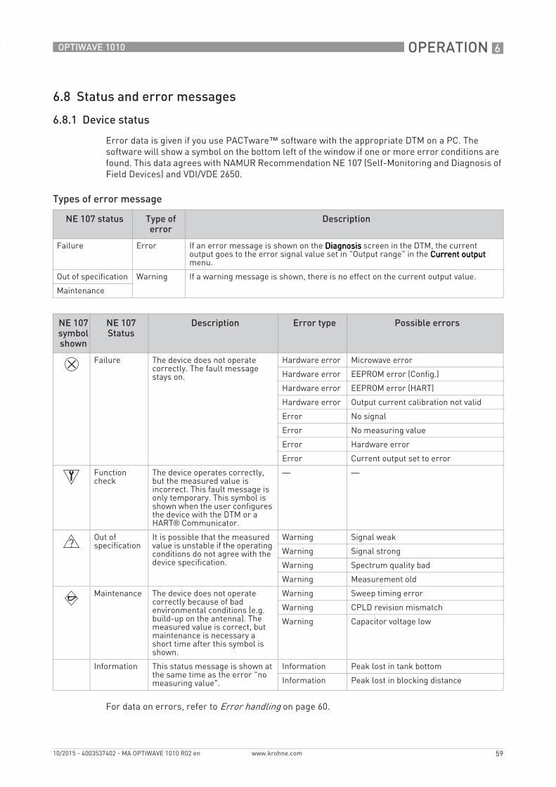
OPERATION 6
59
OPTIWAVE 1010
www.krohne.com10/2015 - 4003537402 - MA OPTIWAVE 1010 R02 en
6.8 Status and error messages
6.8.1 Device status
Error data is given if you use PACTware™ software with the appropriate DTM on a PC. The software will show a symbol on the bottom left of the window if one or more error conditions are found. This data agrees with NAMUR Recommendation NE 107 (Self-Monitoring and Diagnosis of Field Devices) and VDI/VDE 2650.
Types of error message
For data on errors, refer to Error handling on page 60.
NE 107 status Type of error
Description
Failure Error If an error message is shown on the DiagnosisDiagnosisDiagnosisDiagnosis screen in the DTM, the current output goes to the error signal value set in "Output range" in the Current outputCurrent outputCurrent outputCurrent output menu.
Out of specification Warning If a warning message is shown, there is no effect on the current output value.
Maintenance
NE 107 symbol shown
NE 107 Status
Description Error type Possible errors
Failure The device does not operate correctly. The fault message stays on.
Hardware error Microwave error
Hardware error EEPROM error (Config.)
Hardware error EEPROM error (HART)
Hardware error Output current calibration not valid
Error No signal
Error No measuring value
Error Hardware error
Error Current output set to error
Function check
The device operates correctly, but the measured value is incorrect. This fault message is only temporary. This symbol is shown when the user configures the device with the DTM or a HART® Communicator.
— —
Out of specification
It is possible that the measured value is unstable if the operating conditions do not agree with the device specification.
Warning Signal weak
Warning Signal strong
Warning Spectrum quality bad
Warning Measurement old
Maintenance The device does not operate correctly because of bad environmental conditions (e.g. build-up on the antenna). The measured value is correct, but maintenance is necessary a short time after this symbol is shown.
Warning Sweep timing error
Warning CPLD revision mismatch
Warning Capacitor voltage low
Information This status message is shown at the same time as the error "no measuring value".
Information Peak lost in tank bottom
Information Peak lost in blocking distance
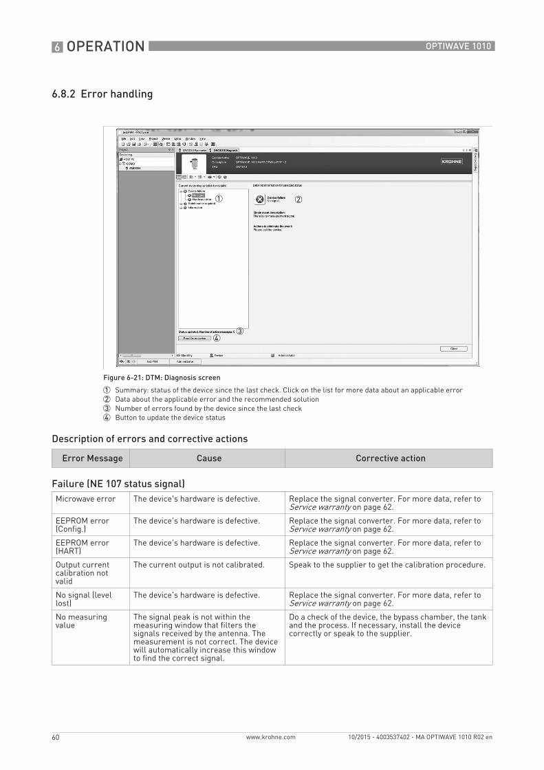
6 OPERATION
60
OPTIWAVE 1010
www.krohne.com 10/2015 - 4003537402 - MA OPTIWAVE 1010 R02 en
6.8.2 Error handling
Description of errors and corrective actions
Figure 6-21: DTM: Diagnosis screen
1 Summary: status of the device since the last check. Click on the list for more data about an applicable error2 Data about the applicable error and the recommended solution3 Number of errors found by the device since the last check4 Button to update the device status
Error Message Cause Corrective action
Failure (NE 107 status signal)Microwave error The device's hardware is defective. Replace the signal converter. For more data, refer to
Service warranty on page 62.
EEPROM error (Config.)
The device's hardware is defective. Replace the signal converter. For more data, refer to Service warranty on page 62.
EEPROM error (HART)
The device's hardware is defective. Replace the signal converter. For more data, refer to Service warranty on page 62.
Output current calibration not valid
The current output is not calibrated. Speak to the supplier to get the calibration procedure.
No signal (level lost)
The device's hardware is defective. Replace the signal converter. For more data, refer to Service warranty on page 62.
No measuring value
The signal peak is not within the measuring window that filters the signals received by the antenna. The measurement is not correct. The device will automatically increase this window to find the correct signal.
Do a check of the device, the bypass chamber, the tank and the process. If necessary, install the device correctly or speak to the supplier.
OPERATION 6
61
OPTIWAVE 1010
www.krohne.com10/2015 - 4003537402 - MA OPTIWAVE 1010 R02 en
Hardware error The device will send this error message if there is a microwave error, EEPROM error (Config.), EEPROM error (HART) or the current output is not calibrated.
—
Out of specification (NE 107 status signal)Signal weak The signal amplitude is less than the
average value. This can occur if the liquid is agitated or if there is foam in the bypass chamber. If this error occurs frequently, the device will possibly show the "No measuring value" error message. 1
If this error occurs frequently, it is possible that you must install a float with a radar target (if there is no float supplied with the device).
Signal strong This error can occur if there is a large change in signal amplitude. 1
No corrective action is necessary.
Spectrum quality bad
The quality of the spectrum is poor. If this message is temporarily shown, this will not affect the performance of the device. If this message is continuously shown, the measured values can be incorrect. The error message "Measurement old" will then be shown. Possible causes are low reflectivity of the liquid (if there is no float in the bypass chamber) or the inner surface of the bypass chamber is dirty.
Do a check of the device, bypass chamber and the process. Change the device settings. If necessary, contact the supplier.
Measurement old This is a temporary error message. If the device cannot get a measurement in this time limit, the displayed measurement is no longer correct. The voltage is possibly too low. If the device continues to show the message "Spectrum quality bad", then this message is also shown.
Do a check of the voltage at the device terminals. Refer also to the error message "Spectrum quality bad".
Maintenance (NE 107 status signal)Sweep timing error It is possible that the device's hardware
is defective.If this error message continues or occurs regularly, replace the signal converter.
CPLD revision mismatch
The CLPD software was not updated or the device's hardware is defective.
Replace the converter. For more data, refer to How to replace the signal converter on page 63.
Capacitor voltage low
It is possible that the device's hardware is defective.
Do a check of the power supply at the device terminals. Make sure that voltage values are in the specified limits. If the voltage is correct, replace the signal converter.
InformationCurrent output set to error
The device current output is at its error value. The error value is set in the Current outputCurrent outputCurrent outputCurrent output menu. For more data, refer to Current output on page 53.
Do a check of the "Diagnosis" screen in the DTM to find the problem. Then refer to the other errors shown in this list. For more data, refer to Diagnosis window on page 38.
Peak lost in tank bottom
The tank is possibly empty. The device will display the tank bottom measurement.
If you fill the tank, the device will measure again.
Peak lost in blocking distance
The level is in the blocking distance. There is a risk that the product will overflow and/or cover the device.
Remove some of the product until the level is below the blocking distance.
1 This error message does not have an effect on the current output signal
Error Message Cause Corrective action
7 SERVICE
62
OPTIWAVE 1010
www.krohne.com 10/2015 - 4003537402 - MA OPTIWAVE 1010 R02 en
7.1 Periodic maintenance
No maintenance is necessary.
7.2 How to replace device components
7.2.1 Service warranty
Servicing by the customer is limited by warranty to:• The removal and installation of the housing. For more data, refer to How to replace the signal
converter on page 63.
For more data on how to prepare the device before you send it back to the supplier, refer to Returning the device to the manufacturer on page 65.
WARNING!Only approved personnel can do an inspection of the device and repairs. If you find a problem, send the device back to the supplier for inspection and/or repairs.
INFORMATION!The converter housing can be detached from the process connection assembly under process conditions.
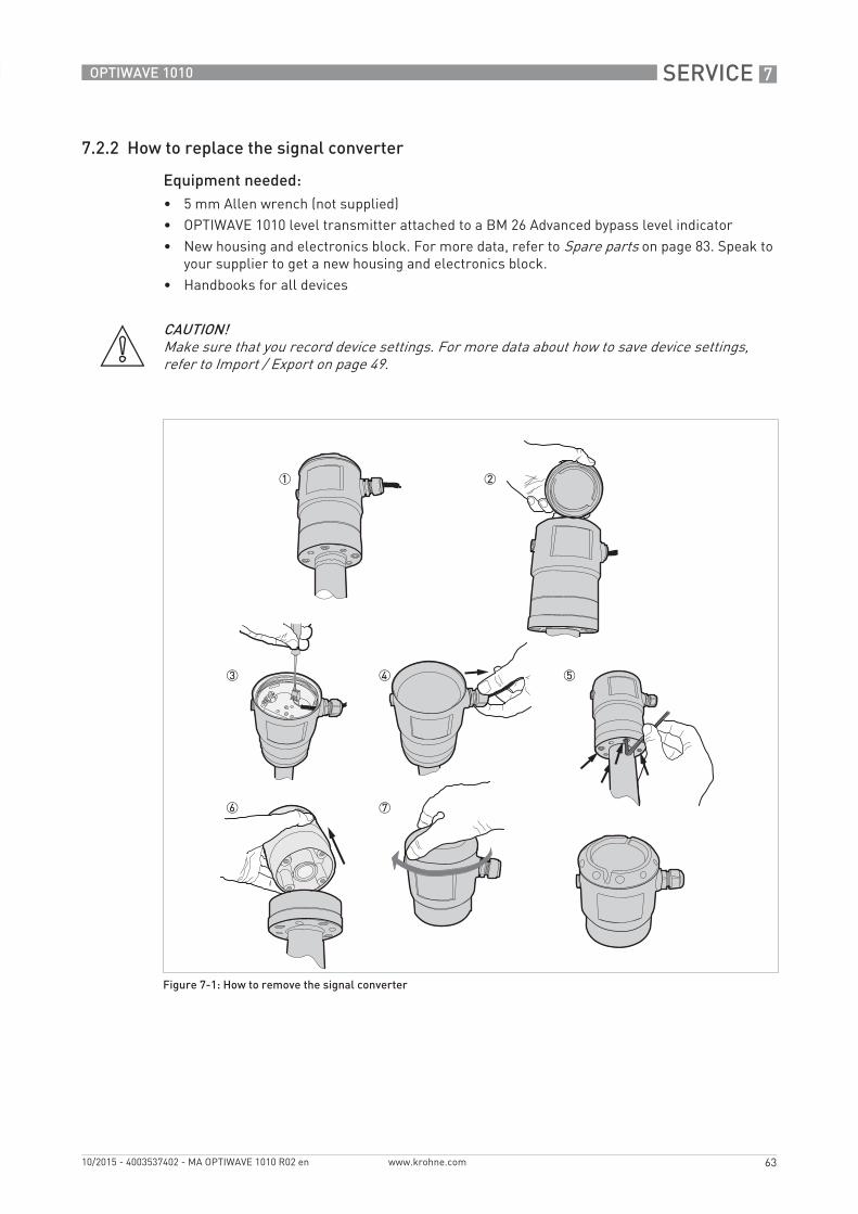
SERVICE 7
63
OPTIWAVE 1010
www.krohne.com10/2015 - 4003537402 - MA OPTIWAVE 1010 R02 en
7.2.2 How to replace the signal converter
Equipment needed:• 5 mm Allen wrench (not supplied)• OPTIWAVE 1010 level transmitter attached to a BM 26 Advanced bypass level indicator• New housing and electronics block. For more data, refer to Spare parts on page 83. Speak to
your supplier to get a new housing and electronics block.• Handbooks for all devices
CAUTION!Make sure that you record device settings. For more data about how to save device settings, refer to Import / Export on page 49.
Figure 7-1: How to remove the signal converter
7 SERVICE
64
OPTIWAVE 1010
www.krohne.com 10/2015 - 4003537402 - MA OPTIWAVE 1010 R02 en
How to remove the signal converter1 De-energize the device.2 Remove the housing cover.3 Disconnect the electrical wires from the terminal block.4 Loosen the cable gland and remove the electrical wire from the housing.5 Use a 5 mm Allen wrench to remove the four bolts shown in the illustration.6 Remove the signal converter.7 Attach the housing cover.i End of the procedure.
How to attach the signal converter1 Remove the housing cover.2 Attach the signal converter. Use a 5 mm Allen wrench to attach the four bolts at the bottom of
the level transmitter.3 Loosen the cable gland and push the electrical wires into the housing.4 Connect the electrical wires to the terminal block.5 Attach the housing cover.i End of the procedure.
7.3 Spare parts availability
The manufacturer adheres to the basic principle that functionally adequate spare parts for each device or each important accessory part will be kept available for a period of 3 years after delivery of the last production run for the device.
This regulation only applies to spare parts which are subject to wear and tear under normal operating conditions.
WARNING!If the device has the aluminium housing option with a distance piece, remove the housing and the distance piece. Do not remove the distance piece from the housing.
INFORMATION!If you want use the configuration set in the device before you replaced the housing, you must load the CFG file that you saved before you did this procedure. For more data about how to load and use device settings, refer to Import / Export on page 49 or refer to How to load settings from the device to PACTware™ on page 41.
SERVICE 7
65
OPTIWAVE 1010
www.krohne.com10/2015 - 4003537402 - MA OPTIWAVE 1010 R02 en
7.4 Availability of services
The manufacturer offers a range of services to support the customer after expiration of the warranty. These include repair, maintenance, technical support and training.
7.5 Returning the device to the manufacturer
7.5.1 General information
This device has been carefully manufactured and tested. If installed and operated in accordance with these operating instructions, it will rarely present any problems.
INFORMATION!For more precise information, please contact your local sales office.
CAUTION!Should you nevertheless need to return a device for inspection or repair, please pay strict attention to the following points:• Due to statutory regulations on environmental protection and safeguarding the health and
safety of the personnel, the manufacturer may only handle, test and repair returned devices that have been in contact with products without risk to personnel and environment.
• This means that the manufacturer can only service this device if it is accompanied by the following certificate (see next section) confirming that the device is safe to handle.
CAUTION!If the device has been operated with toxic, caustic, flammable or water-endangering products, you are kindly requested:• to check and ensure, if necessary by rinsing or neutralising, that all cavities are free from
such dangerous substances,• to enclose a certificate with the device confirming that is safe to handle and stating the
product used.
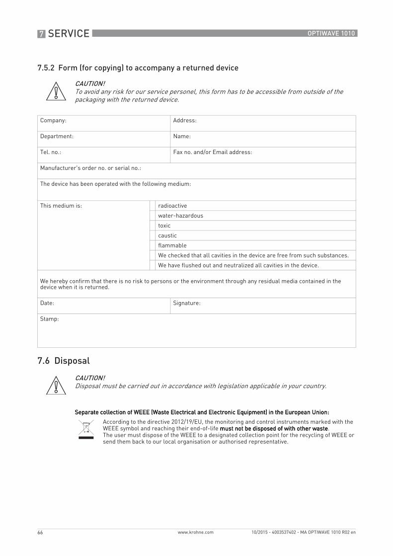
7 SERVICE
66
OPTIWAVE 1010
www.krohne.com 10/2015 - 4003537402 - MA OPTIWAVE 1010 R02 en
7.5.2 Form (for copying) to accompany a returned device
7.6 Disposal
CAUTION!To avoid any risk for our service personel, this form has to be accessible from outside of the packaging with the returned device.
Company: Address:
Department: Name:
Tel. no.: Fax no. and/or Email address:
Manufacturer's order no. or serial no.:
The device has been operated with the following medium:
This medium is: radioactive
water-hazardous
toxic
caustic
flammable
We checked that all cavities in the device are free from such substances.
We have flushed out and neutralized all cavities in the device.
We hereby confirm that there is no risk to persons or the environment through any residual media contained in the device when it is returned.
Date: Signature:
Stamp:
CAUTION!Disposal must be carried out in accordance with legislation applicable in your country.
Separate collection of WEEE (Waste Electrical and Electronic Equipment) in the European Union:Separate collection of WEEE (Waste Electrical and Electronic Equipment) in the European Union:Separate collection of WEEE (Waste Electrical and Electronic Equipment) in the European Union:Separate collection of WEEE (Waste Electrical and Electronic Equipment) in the European Union:
According to the directive 2012/19/EU, the monitoring and control instruments marked with the WEEE symbol and reaching their end-of-life must not be disposed of with other wastemust not be disposed of with other wastemust not be disposed of with other wastemust not be disposed of with other waste.The user must dispose of the WEEE to a designated collection point for the recycling of WEEE or send them back to our local organisation or authorised representative.
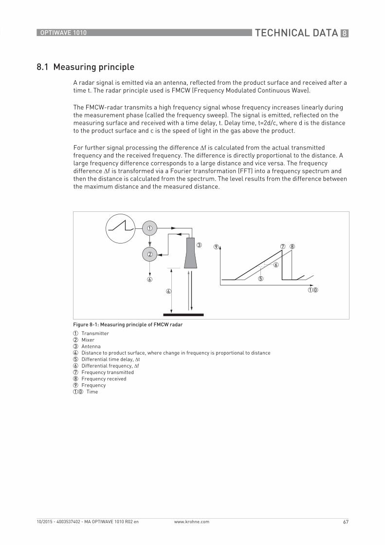
TECHNICAL DATA 8
67
OPTIWAVE 1010
www.krohne.com10/2015 - 4003537402 - MA OPTIWAVE 1010 R02 en
8.1 Measuring principle
A radar signal is emitted via an antenna, reflected from the product surface and received after a time t. The radar principle used is FMCW (Frequency Modulated Continuous Wave).
The FMCW-radar transmits a high frequency signal whose frequency increases linearly during the measurement phase (called the frequency sweep). The signal is emitted, reflected on the measuring surface and received with a time delay, t. Delay time, t=2d/c, where d is the distance to the product surface and c is the speed of light in the gas above the product.
For further signal processing the difference Δf is calculated from the actual transmitted frequency and the received frequency. The difference is directly proportional to the distance. A large frequency difference corresponds to a large distance and vice versa. The frequency difference Δf is transformed via a Fourier transformation (FFT) into a frequency spectrum and then the distance is calculated from the spectrum. The level results from the difference between the maximum distance and the measured distance.
Figure 8-1: Measuring principle of FMCW radar
1 Transmitter2 Mixer3 Antenna4 Distance to product surface, where change in frequency is proportional to distance5 Differential time delay, Δt6 Differential frequency, Δf7 Frequency transmitted8 Frequency received9 Frequency10 Time
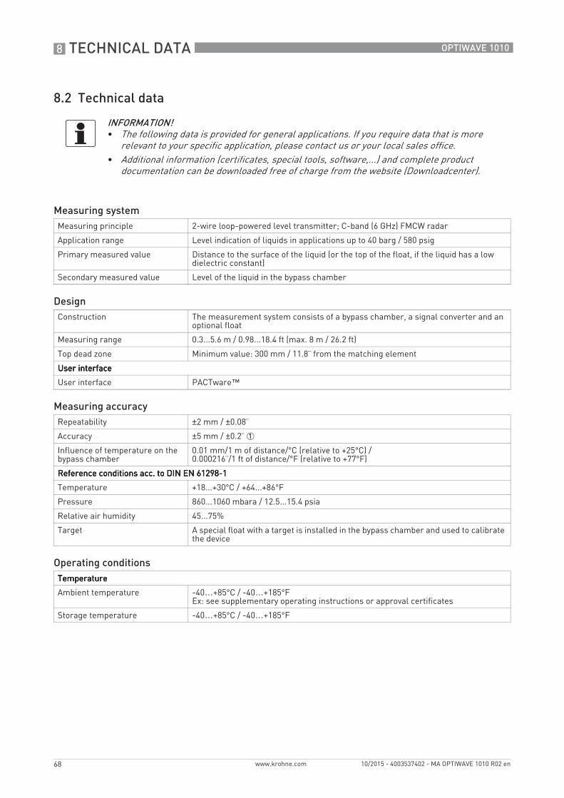
8 TECHNICAL DATA
68
OPTIWAVE 1010
www.krohne.com 10/2015 - 4003537402 - MA OPTIWAVE 1010 R02 en
8.2 Technical data
INFORMATION!• The following data is provided for general applications. If you require data that is more
relevant to your specific application, please contact us or your local sales office.• Additional information (certificates, special tools, software,...) and complete product
documentation can be downloaded free of charge from the website (Downloadcenter).
Measuring systemMeasuring principle 2-wire loop-powered level transmitter; C-band (6 GHz) FMCW radar
Application range Level indication of liquids in applications up to 40 barg / 580 psig
Primary measured value Distance to the surface of the liquid (or the top of the float, if the liquid has a low dielectric constant)
Secondary measured value Level of the liquid in the bypass chamber
DesignConstruction The measurement system consists of a bypass chamber, a signal converter and an
optional float
Measuring range 0.3...5.6 m / 0.98...18.4 ft (max. 8 m / 26.2 ft)
Top dead zone Minimum value: 300 mm / 11.8¨ from the matching element
User interfaceUser interfaceUser interfaceUser interface
User interface PACTware™
Measuring accuracyRepeatability ±2 mm / ±0.08¨
Accuracy ±5 mm / ±0.2¨ 1
Influence of temperature on the bypass chamber
0.01 mm/1 m of distance/°C (relative to +25°C) /0.000216¨/1 ft of distance/°F (relative to +77°F)
Reference conditions acc. to DIN EN 61298-1Reference conditions acc. to DIN EN 61298-1Reference conditions acc. to DIN EN 61298-1Reference conditions acc. to DIN EN 61298-1
Temperature +18...+30°C / +64...+86°F
Pressure 860...1060 mbara / 12.5...15.4 psia
Relative air humidity 45...75%
Target A special float with a target is installed in the bypass chamber and used to calibrate the device
Operating conditionsTemperatureTemperatureTemperatureTemperature
Ambient temperature -40…+85°C / -40…+185°FEx: see supplementary operating instructions or approval certificates
Storage temperature -40…+85°C / -40…+185°F
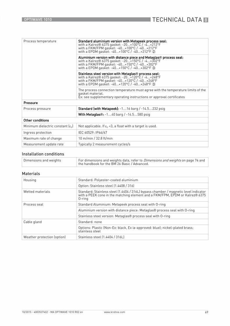
TECHNICAL DATA 8
69
OPTIWAVE 1010
www.krohne.com10/2015 - 4003537402 - MA OPTIWAVE 1010 R02 en
Process temperature Standard aluminium version with Metapeek process seal:Standard aluminium version with Metapeek process seal:Standard aluminium version with Metapeek process seal:Standard aluminium version with Metapeek process seal:with a Kalrez® 6375 gasket: -20...+100°C / -4...+212°Fwith a FKM/FPM gasket: -40...+100°C / -40...+212°Fwith a EPDM gasket: -40...+100°C / -40...+212°F 2
Aluminium version with distance piece and MetaglasAluminium version with distance piece and MetaglasAluminium version with distance piece and MetaglasAluminium version with distance piece and Metaglas® process seal: process seal: process seal: process seal:with a Kalrez® 6375 gasket: -20...+150°C / -4...+302°Fwith a FKM/FPM gasket: -40...+150°C / -40...+302°Fwith a EPDM gasket: -40...+150°C / -40...+302°F 3
Stainless steel version with MetaglasStainless steel version with MetaglasStainless steel version with MetaglasStainless steel version with Metaglas® process seal: process seal: process seal: process seal:with a Kalrez® 6375 gasket: -20...+120°C / -4...+248°Fwith a FKM/FPM gasket: -40...+120°C / -40...+248°Fwith a EPDM gasket: -40...+120°C / -40...+248°F 3
The process connection temperature must agree with the temperature limits of the gasket material.Ex: see supplementary operating instructions or approval certificates
PressurePressurePressurePressure
Process pressure Standard (with Metapeek):Standard (with Metapeek):Standard (with Metapeek):Standard (with Metapeek): -1…16 barg / -14.5…232 psig
With MetaglasWith MetaglasWith MetaglasWith Metaglas®:::: -1…40 barg / -14.5…580 psig
Other conditionsOther conditionsOther conditionsOther conditions
Minimum dielectric constant (εr) Not applicable. If εr <3, a float with a target is used.
Ingress protection IEC 60529: IP66/67
Maximum rate of change 10 m/min / 32.8 ft/min
Measurement update rate Typically 2 measurement cycles/s
Installation conditionsDimensions and weights For dimensions and weights data, refer to Dimensions and weights on page 74 and
the handbook for the BM 26 Basic / Advanced.
MaterialsHousing Standard: Polyester-coated aluminium
Option: Stainless steel (1.4408 / 316)
Wetted materials Standard: Stainless steel (1.4404 / 316L) bypass chamber / magnetic level indicator with a PEEK cone in the matching element and a FKM/FPM, EPDM or Kalrez® 6375 O-ring
Process seal Standard Aluminium: Metapeek process seal with O-ring
Aluminium version with distance piece: Metaglas® process seal with O-ring
Stainless steel version: Metaglas® process seal with O-ring
Cable gland Standard: none
Options: Plastic (Non-Ex: black, Ex ia-approved: blue); nickel-plated brass; stainless steel
Weather protection (option) Stainless steel (1.4404 / 316L)
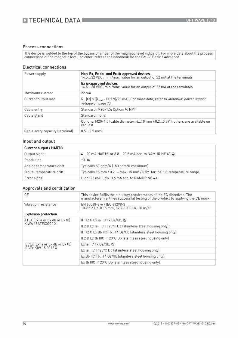
8 TECHNICAL DATA
70
OPTIWAVE 1010
www.krohne.com 10/2015 - 4003537402 - MA OPTIWAVE 1010 R02 en
Process connectionsThe device is welded to the top of the bypass chamber of the magnetic level indicator. For more data about the process connections of the magnetic level indicator, refer to the handbook for the BM 26 Basic / Advanced.
Electrical connectionsPower supply Non-Ex, Ex db- and Ex tb-approved devicesNon-Ex, Ex db- and Ex tb-approved devicesNon-Ex, Ex db- and Ex tb-approved devicesNon-Ex, Ex db- and Ex tb-approved devices
14.5…32 VDC; min./max. value for an output of 22 mA at the terminals
Ex ia-approved devicesEx ia-approved devicesEx ia-approved devicesEx ia-approved devices14.5…30 VDC; min./max. value for an output of 22 mA at the terminals
Maximum current 22 mA
Current output load RL [Ω] ≤ ((Uext -14.5 V)/22 mA). For more data, refer to Minimum power supply voltage on page 73.
Cable entry Standard: M20×1.5; Option: ½ NPT
Cable gland Standard: none
Options: M20×1.5 (cable diameter: 6...10 mm / 0.2...0.39¨); others are available on request
Cable entry capacity (terminal) 0.5…2.5 mm²
Input and outputCurrent output / HARTCurrent output / HARTCurrent output / HARTCurrent output / HART®Output signal 4…20 mA HART® or 3.8…20.5 mA acc. to NAMUR NE 43 4
Resolution ±3 µA
Analog temperature drift Typically 50 ppm/K (150 ppm/K maximum)
Digital temperature drift Typically ±5 mm / 0.2¨ – max. 15 mm / 0.59¨ for the full temperature range
Error signal High: 22 mA; Low: 3.6 mA acc. to NAMUR NE 43
Approvals and certificationCE This device fulfils the statutory requirements of the EC directives. The
manufacturer certifies successful testing of the product by applying the CE mark.
Vibration resistance EN 60068-2-6 / IEC 61298-310-82.2 Hz: 0.15 mm; 82.2-1000 Hz: 20 m/s²
Explosion protectionExplosion protectionExplosion protectionExplosion protection
ATEX (Ex ia or Ex db or Ex tb)KIWA 15ATEX0022 X
II 1/2 G Ex ia IIC Tx Ga/Gb; 5
II 2 D Ex ia IIIC T120°C Db (stainless steel housing only);
II 1/2 G Ex db IIC T6...T4 Ga/Gb (stainless steel housing only);
II 2 D Ex tb IIIC T120°C Db (stainless steel housing only)
IECEx (Ex ia or Ex db or Ex tb)IECEx KIW 15.0012 X
Ex ia IIC Tx Ga/Gb; 5
Ex ia IIIC T120°C Db (stainless steel housing only);
Ex db IIC T6...T4 Ga/Gb (stainless steel housing only);
Ex tb IIIC T120°C Db (stainless steel housing only)
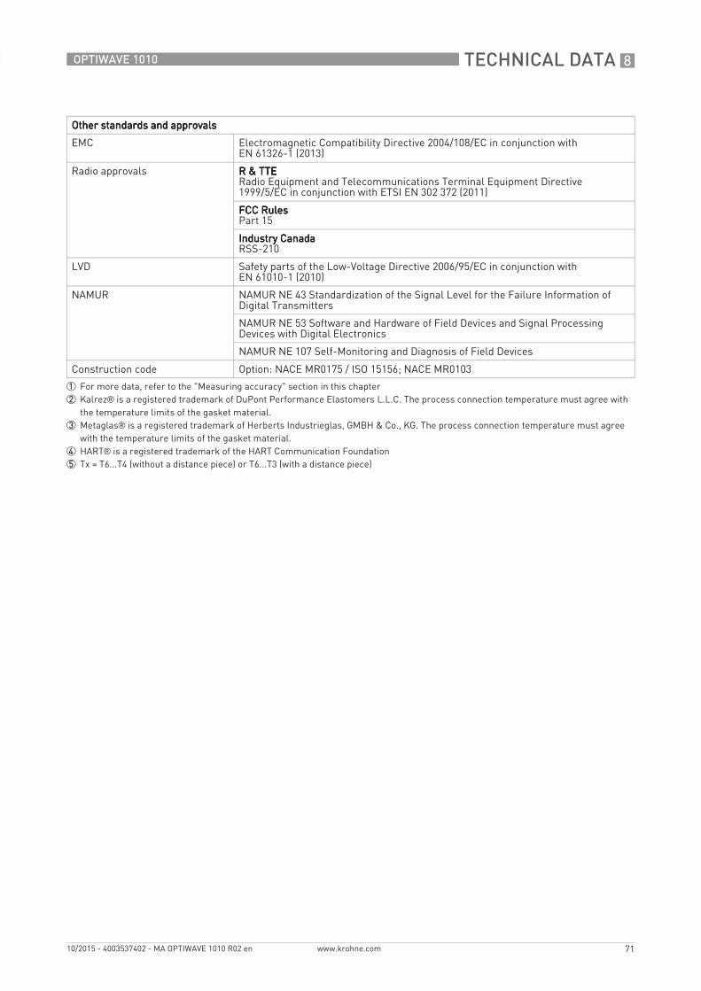
TECHNICAL DATA 8
71
OPTIWAVE 1010
www.krohne.com10/2015 - 4003537402 - MA OPTIWAVE 1010 R02 en
Other standards and approvalsOther standards and approvalsOther standards and approvalsOther standards and approvals
EMC Electromagnetic Compatibility Directive 2004/108/EC in conjunction with EN 61326-1 (2013)
Radio approvals R & TTER & TTER & TTER & TTERadio Equipment and Telecommunications Terminal Equipment Directive 1999/5/EC in conjunction with ETSI EN 302 372 (2011)
FCC RulesFCC RulesFCC RulesFCC RulesPart 15
Industry CanadaIndustry CanadaIndustry CanadaIndustry CanadaRSS-210
LVD Safety parts of the Low-Voltage Directive 2006/95/EC in conjunction with EN 61010-1 (2010)
NAMUR NAMUR NE 43 Standardization of the Signal Level for the Failure Information of Digital Transmitters
NAMUR NE 53 Software and Hardware of Field Devices and Signal Processing Devices with Digital Electronics
NAMUR NE 107 Self-Monitoring and Diagnosis of Field Devices
Construction code Option: NACE MR0175 / ISO 15156; NACE MR0103
1 For more data, refer to the "Measuring accuracy" section in this chapter2 Kalrez® is a registered trademark of DuPont Performance Elastomers L.L.C. The process connection temperature must agree with
the temperature limits of the gasket material.3 Metaglas® is a registered trademark of Herberts Industrieglas, GMBH & Co., KG. The process connection temperature must agree
with the temperature limits of the gasket material.4 HART® is a registered trademark of the HART Communication Foundation5 Tx = T6...T4 (without a distance piece) or T6...T3 (with a distance piece)
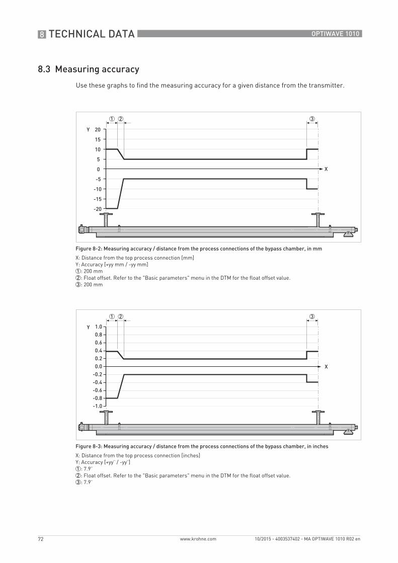
8 TECHNICAL DATA
72
OPTIWAVE 1010
www.krohne.com 10/2015 - 4003537402 - MA OPTIWAVE 1010 R02 en
8.3 Measuring accuracy
Use these graphs to find the measuring accuracy for a given distance from the transmitter.
Figure 8-2: Measuring accuracy / distance from the process connections of the bypass chamber, in mm
X: Distance from the top process connection [mm]Y: Accuracy [+yy mm / -yy mm]1: 200 mm2: Float offset. Refer to the "Basic parameters" menu in the DTM for the float offset value.3: 200 mm
Figure 8-3: Measuring accuracy / distance from the process connections of the bypass chamber, in inches
X: Distance from the top process connection [inches]Y: Accuracy [+yy¨ / -yy¨]1: 7.9¨2: Float offset. Refer to the "Basic parameters" menu in the DTM for the float offset value.3: 7.9¨
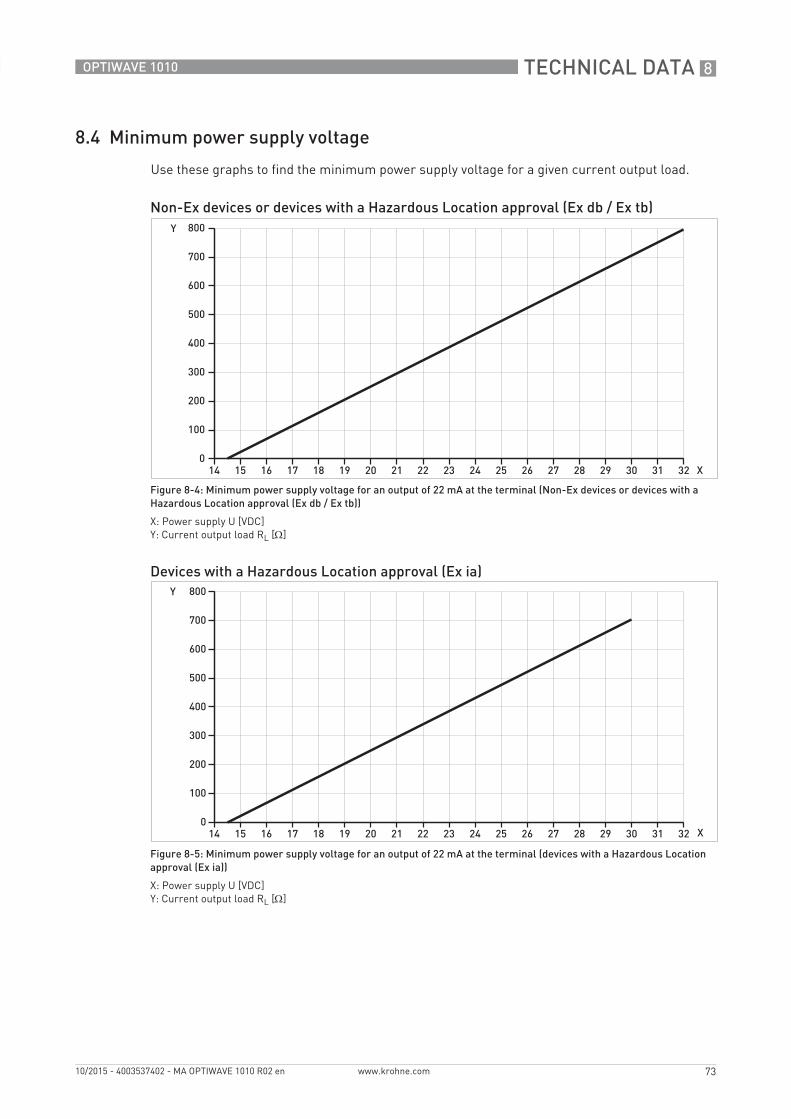
TECHNICAL DATA 8
73
OPTIWAVE 1010
www.krohne.com10/2015 - 4003537402 - MA OPTIWAVE 1010 R02 en
8.4 Minimum power supply voltage
Use these graphs to find the minimum power supply voltage for a given current output load.
Non-Ex devices or devices with a Hazardous Location approval (Ex db / Ex tb)
Figure 8-4: Minimum power supply voltage for an output of 22 mA at the terminal (Non-Ex devices or devices with a Hazardous Location approval (Ex db / Ex tb))
X: Power supply U [VDC]Y: Current output load RL [Ω]
Devices with a Hazardous Location approval (Ex ia)
Figure 8-5: Minimum power supply voltage for an output of 22 mA at the terminal (devices with a Hazardous Location approval (Ex ia))
X: Power supply U [VDC]Y: Current output load RL [Ω]
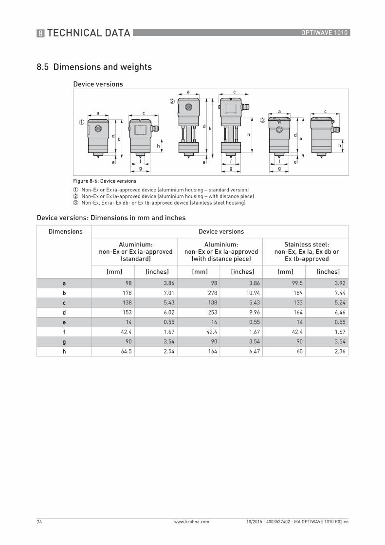
8 TECHNICAL DATA
74
OPTIWAVE 1010
www.krohne.com 10/2015 - 4003537402 - MA OPTIWAVE 1010 R02 en
8.5 Dimensions and weights
Device versions: Dimensions in mm and inches
Device versions
Figure 8-6: Device versions
1 Non-Ex or Ex ia-approved device (aluminium housing – standard version)2 Non-Ex or Ex ia-approved device (aluminium housing – with distance piece)3 Non-Ex, Ex ia- Ex db- or Ex tb-approved device (stainless steel housing)
Dimensions Device versions
Aluminium:non-Ex or Ex ia-approved
(standard)
Aluminium:non-Ex or Ex ia-approved
(with distance piece)
Stainless steel:non-Ex, Ex ia, Ex db or
Ex tb-approved
[mm] [inches] [mm] [inches] [mm] [inches]
aaaa 98 3.86 98 3.86 99.5 3.92
bbbb 178 7.01 278 10.94 189 7.44
cccc 138 5.43 138 5.43 133 5.24
dddd 153 6.02 253 9.96 164 6.46
eeee 14 0.55 14 0.55 14 0.55
ffff 42.4 1.67 42.4 1.67 42.4 1.67
gggg 90 3.54 90 3.54 90 3.54
hhhh 64.5 2.54 164 6.47 60 2.36
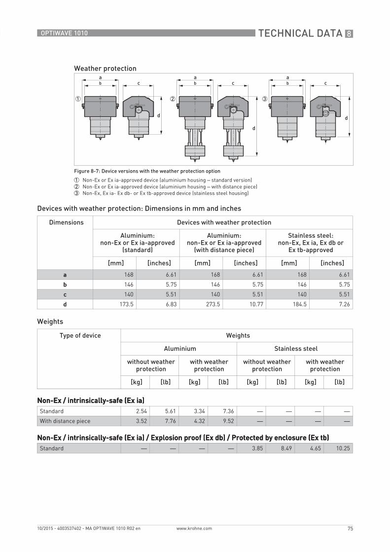
TECHNICAL DATA 8
75
OPTIWAVE 1010
www.krohne.com10/2015 - 4003537402 - MA OPTIWAVE 1010 R02 en
Devices with weather protection: Dimensions in mm and inches
Weights
Weather protection
Figure 8-7: Device versions with the weather protection option
1 Non-Ex or Ex ia-approved device (aluminium housing – standard version)2 Non-Ex or Ex ia-approved device (aluminium housing – with distance piece)3 Non-Ex, Ex ia- Ex db- or Ex tb-approved device (stainless steel housing)
Dimensions Devices with weather protection
Aluminium:non-Ex or Ex ia-approved
(standard)
Aluminium:non-Ex or Ex ia-approved
(with distance piece)
Stainless steel:non-Ex, Ex ia, Ex db or
Ex tb-approved
[mm] [inches] [mm] [inches] [mm] [inches]
aaaa 168 6.61 168 6.61 168 6.61
bbbb 146 5.75 146 5.75 146 5.75
cccc 140 5.51 140 5.51 140 5.51
dddd 173.5 6.83 273.5 10.77 184.5 7.26
Type of device Weights
Aluminium Stainless steel
without weather protection
with weather protection
without weather protection
with weather protection
[kg] [lb] [kg] [lb] [kg] [lb] [kg] [lb]
Non-Ex / intrinsically-safe (Ex ia)Non-Ex / intrinsically-safe (Ex ia)Non-Ex / intrinsically-safe (Ex ia)Non-Ex / intrinsically-safe (Ex ia)Standard 2.54 5.61 3.34 7.36 — — — —
With distance piece 3.52 7.76 4.32 9.52 — — — —
Non-Ex / intrinsically-safe (Ex ia) / Explosion proof (Ex db) / Protected by enclosure (Ex tb)Non-Ex / intrinsically-safe (Ex ia) / Explosion proof (Ex db) / Protected by enclosure (Ex tb)Non-Ex / intrinsically-safe (Ex ia) / Explosion proof (Ex db) / Protected by enclosure (Ex tb)Non-Ex / intrinsically-safe (Ex ia) / Explosion proof (Ex db) / Protected by enclosure (Ex tb)Standard — — — — 3.85 8.49 4.65 10.25
9 DESCRIPTION OF HART INTERFACE
76
OPTIWAVE 1010
www.krohne.com 10/2015 - 4003537402 - MA OPTIWAVE 1010 R02 en
9.1 General description
The HART® Protocol is an open digital communication protocol for industry. It is free to use by anyone. It is included in the software embedded in signal converters of HART-compatible devices.
There are 2 classes of devices which support the HART® Protocol: operating devices and field devices. There are 2 classes of operating devices (Master): PC-supported workstations (Primary Master) and manual control units (Secondary Master). These can be used in control centres and other locations. HART® field devices include sensors, converters and actuators. Field devices include 2-wire and 4-wire devices, and also intrinsically-safe versions for use in hazardous areas.
There are 2 primary operation modes for HART-compatible devices: point-to-point mode and multi-drop mode.
If the device is used in point-to-point mode, the HART® Protocol uses the Bell 202 Frequency Shift Keying (FSK) standard to put a digital signal on top of the 4...20 mA signal. The connected device sends and receives digital signals that agree with the HART® Protocol, and sends analog signals at the same time. Only 1 device can be connected to the signal cable.
If the device is used in multi-drop mode, the network only uses a digital signal that agrees with the HART® Protocol. The loop current is set to 4 mA. You can connect a maximum of 15 devices to the signal cable.
An FSK or HART® modem is included in field devices and manual control units. It is necessary to have an external modem for PC-supported workstations. The external modem is connected to the serial interface.
9.2 Software description
HART® identification codes and revision numbers
Manufacturer ID: 0x45
Device: 0xBF
Device Revision: 1
DD Revision 1
HART® Universal Revision: 6
FC 475 system SW.Rev.: ≥ 3.8
AMS version: ≥ 12.0
PDM version: ≥ 8.1
FDT version: 1.2
DESCRIPTION OF HART INTERFACE 9
77
OPTIWAVE 1010
www.krohne.com10/2015 - 4003537402 - MA OPTIWAVE 1010 R02 en
9.3 Connection variants
The signal converter is a 2-wire device with 4...20 mA current output and HART® interface.
• Multi-Drop Mode is supportedMulti-Drop Mode is supportedMulti-Drop Mode is supportedMulti-Drop Mode is supportedIn a Multi-Drop communication system, more than 1 device is connected to a common transmission cable.
• Burst Mode is not supportedBurst Mode is not supportedBurst Mode is not supportedBurst Mode is not supported
There are two ways of using the HART® communication:• as Point-to-Point connection and• as Multi-Drop connection with 2-wire connection.
9.3.1 Point-to-Point connection - analogue / digital mode
Point-to-Point connection between the signal converter and the HART® Master.
The current output of the device is passive.
Also refer to Point-to-point connection on page 29.
9.3.2 Multi-Drop connection (2-wire connection)
The device can operate in a network with a device address from 1 to 63.
For an illustration of multi-drop networks, refer to Multi-drop networks on page 30.
9.4 HART® device variables
The HART® dynamic variables PV (Primary Variable), SV (Secondary Variable), TV (Third Variable) and QV (Fourth Variable) can be assigned to any of the device variables.
The HART® dynamic variable PV is always connected to the HART® current output which is, for example, assigned to level measurement.
9 DESCRIPTION OF HART INTERFACE
78
OPTIWAVE 1010
www.krohne.com 10/2015 - 4003537402 - MA OPTIWAVE 1010 R02 en
9.5 Field Communicator 475 (FC 475)
The Field Communicator is a hand terminal from Emerson Process Management that is designed to configure HART® and Foundation Fieldbus devices. Device Descriptions (DDs) are used to integrate different devices into the Field Communicator.
9.5.1 Installation
System and software requirements for the Field Communicator• System card that includes the "Easy Upgrade Option"• Field Communicator Easy Upgrade Programming Utility
• HART® Device Description file
For more data, refer to the Field Communicator User’s Manual.
9.5.2 Operation
The Field Communicator and the device's local display use almost the same procedures to operate the signal converter. The online help for each menu item refers to the function number given to each menu item on the local device display. Protection of settings is the same as on the device's local display.
The Field Communicator always saves a complete configuration for communication with AMS.
For more data, refer to HART® menu tree for Basic-DD on page 79.
9.6 Field Device Tool / Device Type Manager (FDT / DTM)
9.6.1 Installation
Before you operate the device, the Device Type Manager (Device DTM) must be installed in the Field Device Tool Container. This .msi file is given on the DVD-ROM supplied with the device. You can also download the file from our website. For installation and configuration data, refer to the documentation that is supplied with the Device DTM on the DVD-ROM or in the "Downloads" section of the website.
9.6.2 Operation
The DTM and the device's local display use almost the same procedures to operate the signal converter. For more data, refer to Operation on page 40.
CAUTION!The Field Communicator cannot be used to correctly configure, operate or read data from the device unless the Device Description (DD) file is installed.
INFORMATION!The Field Communicator will not give you access to the service menu. A simulation is only possible for current outputs.
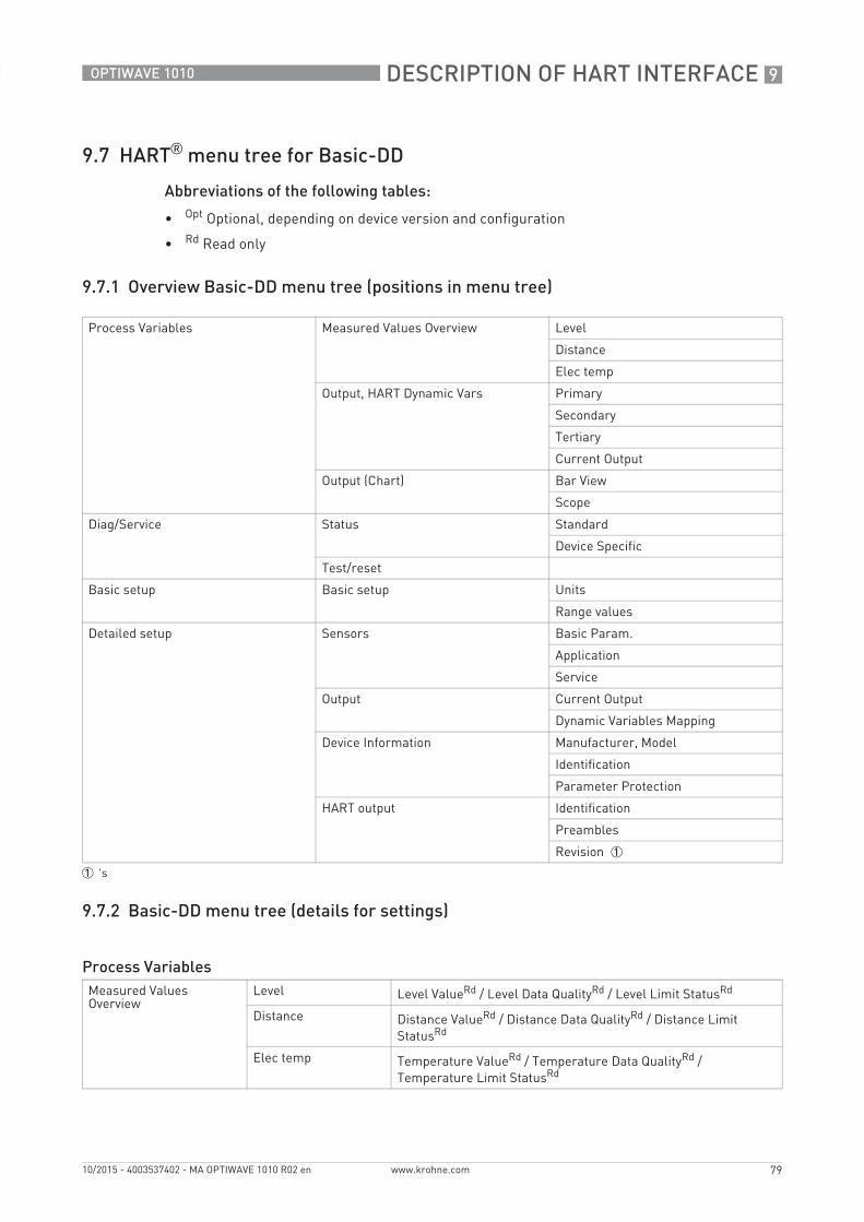
DESCRIPTION OF HART INTERFACE 9
79
OPTIWAVE 1010
www.krohne.com10/2015 - 4003537402 - MA OPTIWAVE 1010 R02 en
9.7 HART® menu tree for Basic-DD
Abbreviations of the following tables:
• Opt Optional, depending on device version and configuration
• Rd Read only
9.7.1 Overview Basic-DD menu tree (positions in menu tree)
9.7.2 Basic-DD menu tree (details for settings)
Process Variables Measured Values Overview Level
Distance
Elec temp
Output, HART Dynamic Vars Primary
Secondary
Tertiary
Current Output
Output (Chart) Bar View
Scope
Diag/Service Status Standard
Device Specific
Test/reset
Basic setup Basic setup Units
Range values
Detailed setup Sensors Basic Param.
Application
Service
Output Current Output
Dynamic Variables Mapping
Device Information Manufacturer, Model
Identification
Parameter Protection
HART output Identification
Preambles
Revision 1
1 's
Process VariablesMeasured Values Overview
Level Level ValueRd / Level Data QualityRd / Level Limit StatusRd
Distance Distance ValueRd / Distance Data QualityRd / Distance Limit StatusRd
Elec temp Temperature ValueRd / Temperature Data QualityRd / Temperature Limit StatusRd
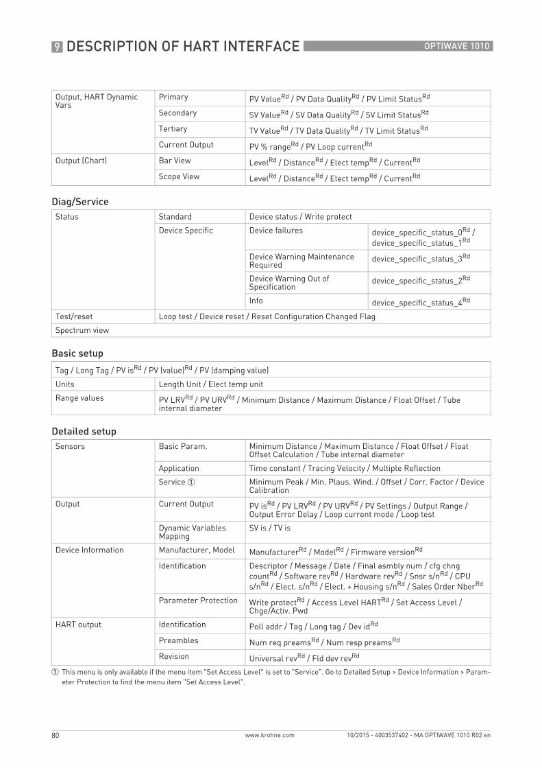
9 DESCRIPTION OF HART INTERFACE
80
OPTIWAVE 1010
www.krohne.com 10/2015 - 4003537402 - MA OPTIWAVE 1010 R02 en
Output, HART Dynamic Vars
Primary PV ValueRd / PV Data QualityRd / PV Limit StatusRd
Secondary SV ValueRd / SV Data QualityRd / SV Limit StatusRd
Tertiary TV ValueRd / TV Data QualityRd / TV Limit StatusRd
Current Output PV % rangeRd / PV Loop currentRd
Output (Chart) Bar View LevelRd / DistanceRd / Elect tempRd / CurrentRd
Scope View LevelRd / DistanceRd / Elect tempRd / CurrentRd
Diag/ServiceStatus Standard Device status / Write protect
Device Specific Device failures device_specific_status_0Rd / device_specific_status_1Rd
Device Warning Maintenance Required
device_specific_status_3Rd
Device Warning Out of Specification
device_specific_status_2Rd
Info device_specific_status_4Rd
Test/reset Loop test / Device reset / Reset Configuration Changed Flag
Spectrum view
Basic setup
Tag / Long Tag / PV isRd / PV (value)Rd / PV (damping value)
Units Length Unit / Elect temp unit
Range values PV LRVRd / PV URVRd / Minimum Distance / Maximum Distance / Float Offset / Tube internal diameter
Detailed setupSensors Basic Param. Minimum Distance / Maximum Distance / Float Offset / Float
Offset Calculation / Tube internal diameter
Application Time constant / Tracing Velocity / Multiple Reflection
Service 1 Minimum Peak / Min. Plaus. Wind. / Offset / Corr. Factor / Device Calibration
Output Current Output PV isRd / PV LRVRd / PV URVRd / PV Settings / Output Range / Output Error Delay / Loop current mode / Loop test
Dynamic Variables Mapping
SV is / TV is
Device Information Manufacturer, Model ManufacturerRd / ModelRd / Firmware versionRd
Identification Descriptor / Message / Date / Final asmbly num / cfg chng countRd / Software revRd / Hardware revRd / Snsr s/nRd / CPU s/nRd / Elect. s/nRd / Elect. + Housing s/nRd / Sales Order NberRd
Parameter Protection Write protectRd / Access Level HARTRd / Set Access Level / Chge/Activ. Pwd
HART output Identification Poll addr / Tag / Long tag / Dev idRd
Preambles Num req preamsRd / Num resp preamsRd
Revision Universal revRd / Fld dev revRd
1 This menu is only available if the menu item "Set Access Level" is set to "Service". Go to Detailed Setup > Device Information > Param-eter Protection to find the menu item "Set Access Level".
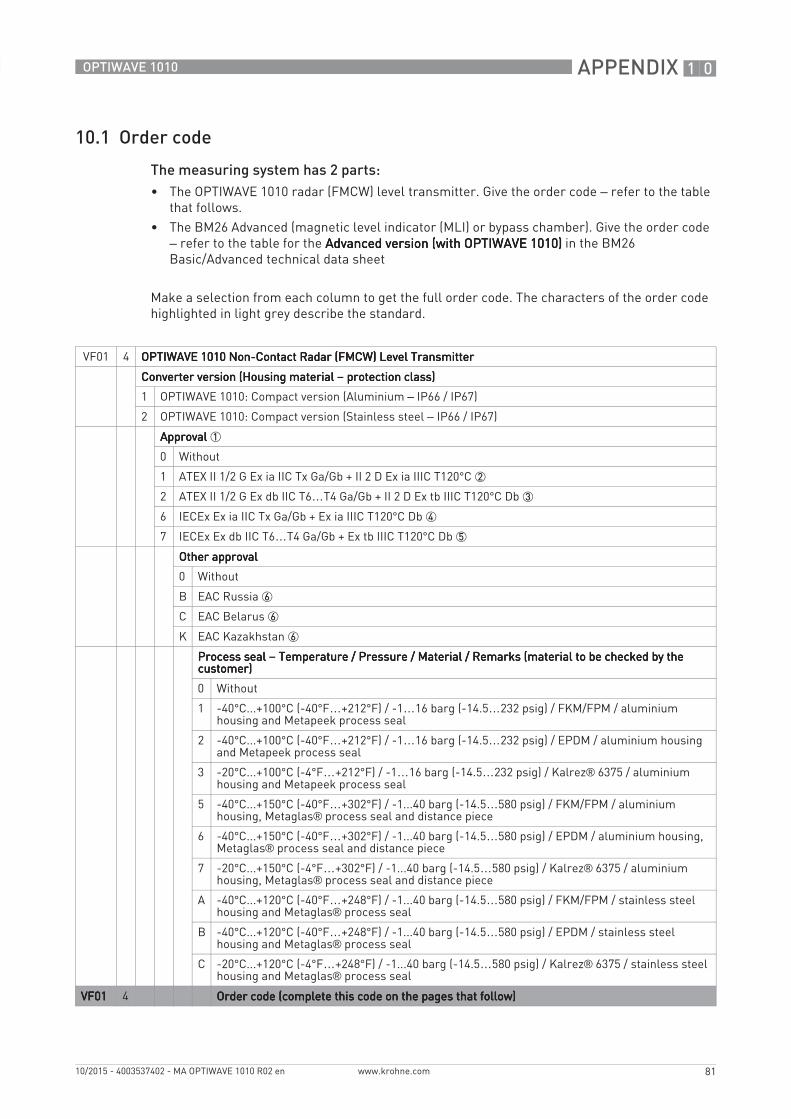
APPENDIX 10
81
OPTIWAVE 1010
www.krohne.com10/2015 - 4003537402 - MA OPTIWAVE 1010 R02 en
10.1 Order code
The measuring system has 2 parts:• The OPTIWAVE 1010 radar (FMCW) level transmitter. Give the order code – refer to the table
that follows.• The BM26 Advanced (magnetic level indicator (MLI) or bypass chamber). Give the order code
– refer to the table for the Advanced version (with OPTIWAVE 1010)Advanced version (with OPTIWAVE 1010)Advanced version (with OPTIWAVE 1010)Advanced version (with OPTIWAVE 1010) in the BM26 Basic/Advanced technical data sheet
Make a selection from each column to get the full order code. The characters of the order code highlighted in light grey describe the standard.
VF01 4 OPTIWAVE 1010 Non-Contact Radar (FMCW) Level TransmitterOPTIWAVE 1010 Non-Contact Radar (FMCW) Level TransmitterOPTIWAVE 1010 Non-Contact Radar (FMCW) Level TransmitterOPTIWAVE 1010 Non-Contact Radar (FMCW) Level Transmitter
Converter version (Housing material Converter version (Housing material Converter version (Housing material Converter version (Housing material – protection class) protection class) protection class) protection class)
1 OPTIWAVE 1010: Compact version (Aluminium – IP66 / IP67)
2 OPTIWAVE 1010: Compact version (Stainless steel – IP66 / IP67)
ApprovalApprovalApprovalApproval 1
0 Without
1 ATEX II 1/2 G Ex ia IIC Tx Ga/Gb + II 2 D Ex ia IIIC T120°C 2
2 ATEX II 1/2 G Ex db IIC T6…T4 Ga/Gb + II 2 D Ex tb IIIC T120°C Db 3
6 IECEx Ex ia IIC Tx Ga/Gb + Ex ia IIIC T120°C Db 4
7 IECEx Ex db IIC T6…T4 Ga/Gb + Ex tb IIIC T120°C Db 5
Other approvalOther approvalOther approvalOther approval
0 Without
B EAC Russia 6
C EAC Belarus 6
K EAC Kazakhstan 6
Process seal Process seal Process seal Process seal – Temperature / Pressure / Material / Remarks (material to be checked by the Temperature / Pressure / Material / Remarks (material to be checked by the Temperature / Pressure / Material / Remarks (material to be checked by the Temperature / Pressure / Material / Remarks (material to be checked by the customer)customer)customer)customer)
0 Without
1 -40°C...+100°C (-40°F…+212°F) / -1…16 barg (-14.5…232 psig) / FKM/FPM / aluminium housing and Metapeek process seal
2 -40°C...+100°C (-40°F…+212°F) / -1…16 barg (-14.5…232 psig) / EPDM / aluminium housing and Metapeek process seal
3 -20°C...+100°C (-4°F…+212°F) / -1…16 barg (-14.5…232 psig) / Kalrez® 6375 / aluminium housing and Metapeek process seal
5 -40°C...+150°C (-40°F…+302°F) / -1...40 barg (-14.5…580 psig) / FKM/FPM / aluminium housing, Metaglas® process seal and distance piece
6 -40°C...+150°C (-40°F…+302°F) / -1...40 barg (-14.5…580 psig) / EPDM / aluminium housing, Metaglas® process seal and distance piece
7 -20°C...+150°C (-4°F…+302°F) / -1...40 barg (-14.5…580 psig) / Kalrez® 6375 / aluminium housing, Metaglas® process seal and distance piece
A -40°C...+120°C (-40°F…+248°F) / -1...40 barg (-14.5…580 psig) / FKM/FPM / stainless steel housing and Metaglas® process seal
B -40°C...+120°C (-40°F…+248°F) / -1...40 barg (-14.5…580 psig) / EPDM / stainless steel housing and Metaglas® process seal
C -20°C...+120°C (-4°F…+248°F) / -1...40 barg (-14.5…580 psig) / Kalrez® 6375 / stainless steel housing and Metaglas® process seal
VF01VF01VF01VF01 4 Order code (complete this code on the pages that follow)Order code (complete this code on the pages that follow)Order code (complete this code on the pages that follow)Order code (complete this code on the pages that follow)
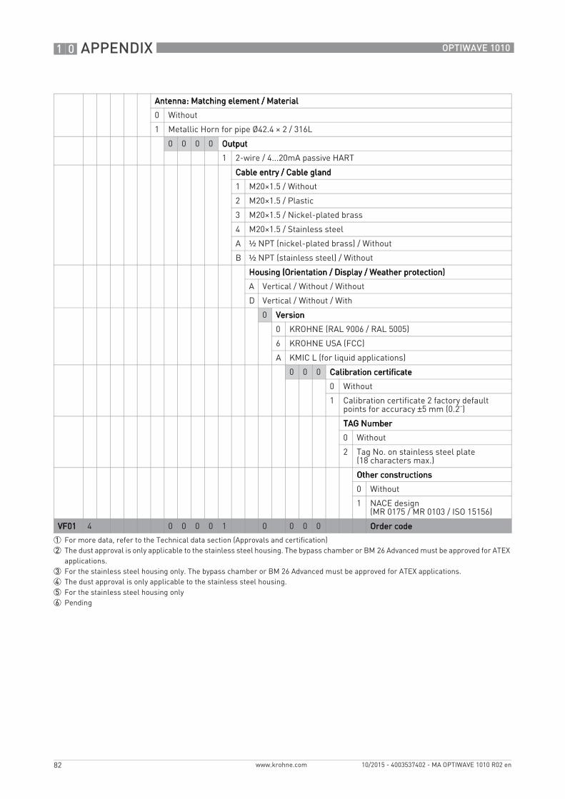
10 APPENDIX
82
OPTIWAVE 1010
www.krohne.com 10/2015 - 4003537402 - MA OPTIWAVE 1010 R02 en
Antenna: Matching element / MaterialAntenna: Matching element / MaterialAntenna: Matching element / MaterialAntenna: Matching element / Material
0 Without
1 Metallic Horn for pipe Ø42.4 × 2 / 316L
0 0 0 0 OutputOutputOutputOutput
1 2-wire / 4...20mA passive HART
Cable entry / Cable glandCable entry / Cable glandCable entry / Cable glandCable entry / Cable gland
1 M20×1.5 / Without
2 M20×1.5 / Plastic
3 M20×1.5 / Nickel-plated brass
4 M20×1.5 / Stainless steel
A ½ NPT (nickel-plated brass) / Without
B ½ NPT (stainless steel) / Without
Housing (Orientation / Display / Weather protection)Housing (Orientation / Display / Weather protection)Housing (Orientation / Display / Weather protection)Housing (Orientation / Display / Weather protection)
A Vertical / Without / Without
D Vertical / Without / With
0 VersionVersionVersionVersion
0 KROHNE (RAL 9006 / RAL 5005)
6 KROHNE USA (FCC)
A KMIC L (for liquid applications)
0 0 0 Calibration certificateCalibration certificateCalibration certificateCalibration certificate
0 Without
1 Calibration certificate 2 factory default points for accuracy ±5 mm (0.2¨)
TAG NumberTAG NumberTAG NumberTAG Number
0 Without
2 Tag No. on stainless steel plate (18 characters max.)
Other constructionsOther constructionsOther constructionsOther constructions
0 Without
1 NACE design (MR 0175 / MR 0103 / ISO 15156)
VF01VF01VF01VF01 4 0 0 0 0 1 0 0 0 0 Order codeOrder codeOrder codeOrder code
1 For more data, refer to the Technical data section (Approvals and certification)2 The dust approval is only applicable to the stainless steel housing. The bypass chamber or BM 26 Advanced must be approved for ATEX
applications.3 For the stainless steel housing only. The bypass chamber or BM 26 Advanced must be approved for ATEX applications.4 The dust approval is only applicable to the stainless steel housing.5 For the stainless steel housing only6 Pending
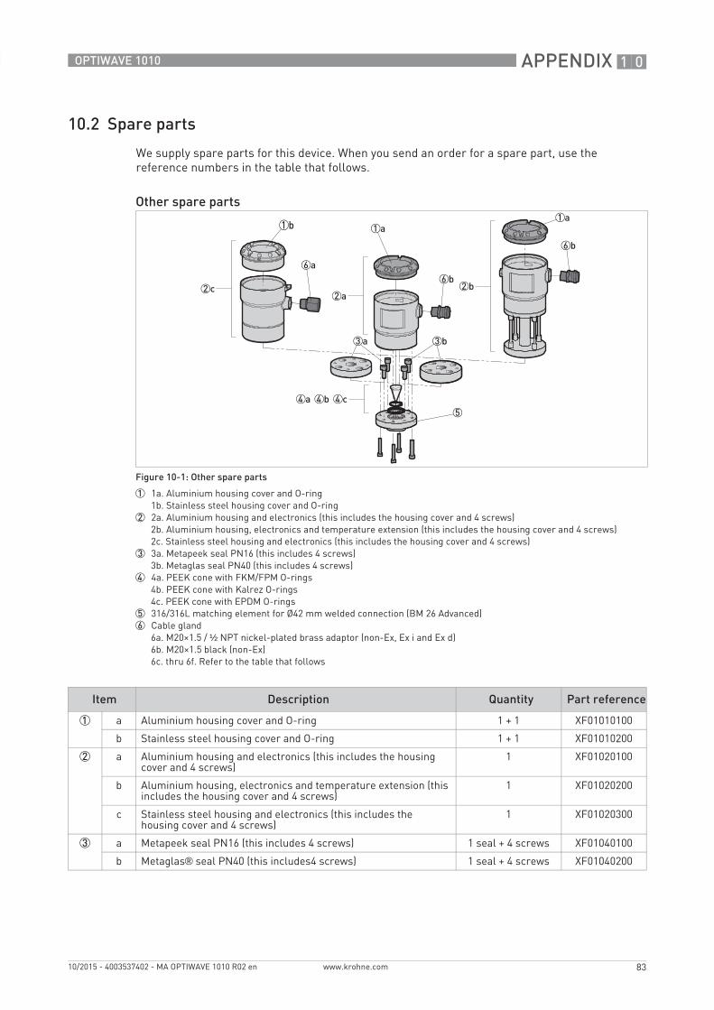
APPENDIX 10
83
OPTIWAVE 1010
www.krohne.com10/2015 - 4003537402 - MA OPTIWAVE 1010 R02 en
10.2 Spare parts
We supply spare parts for this device. When you send an order for a spare part, use the reference numbers in the table that follows.
Other spare parts
Figure 10-1: Other spare parts
1 1a. Aluminium housing cover and O-ring1b. Stainless steel housing cover and O-ring
2 2a. Aluminium housing and electronics (this includes the housing cover and 4 screws)2b. Aluminium housing, electronics and temperature extension (this includes the housing cover and 4 screws)2c. Stainless steel housing and electronics (this includes the housing cover and 4 screws)
3 3a. Metapeek seal PN16 (this includes 4 screws)3b. Metaglas seal PN40 (this includes 4 screws)
4 4a. PEEK cone with FKM/FPM O-rings4b. PEEK cone with Kalrez O-rings4c. PEEK cone with EPDM O-rings
5 316/316L matching element for Ø42 mm welded connection (BM 26 Advanced)6 Cable gland
6a. M20×1.5 / ½ NPT nickel-plated brass adaptor (non-Ex, Ex i and Ex d)6b. M20×1.5 black (non-Ex)6c. thru 6f. Refer to the table that follows
Item Description Quantity Part reference
1 a Aluminium housing cover and O-ring 1 + 1 XF01010100
b Stainless steel housing cover and O-ring 1 + 1 XF01010200
2 a Aluminium housing and electronics (this includes the housing cover and 4 screws)
1 XF01020100
b Aluminium housing, electronics and temperature extension (this includes the housing cover and 4 screws)
1 XF01020200
c Stainless steel housing and electronics (this includes the housing cover and 4 screws)
1 XF01020300
3 a Metapeek seal PN16 (this includes 4 screws) 1 seal + 4 screws XF01040100
b Metaglas® seal PN40 (this includes4 screws) 1 seal + 4 screws XF01040200
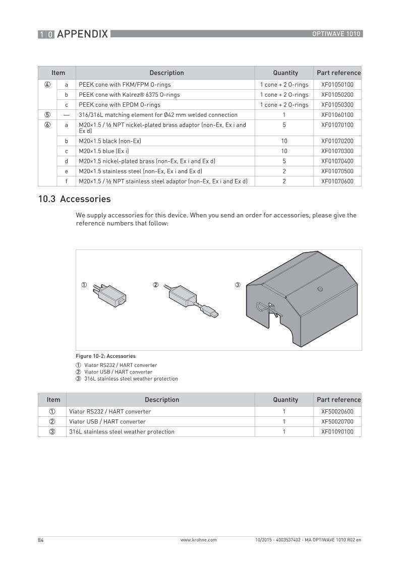
10 APPENDIX
84
OPTIWAVE 1010
www.krohne.com 10/2015 - 4003537402 - MA OPTIWAVE 1010 R02 en
10.3 Accessories
We supply accessories for this device. When you send an order for accessories, please give the reference numbers that follow:
4 a PEEK cone with FKM/FPM O-rings 1 cone + 2 O-rings XF01050100
b PEEK cone with Kalrez® 6375 O-rings 1 cone + 2 O-rings XF01050200
c PEEK cone with EPDM O-rings 1 cone + 2 O-rings XF01050300
5 — 316/316L matching element for Ø42 mm welded connection 1 XF01060100
6 a M20×1.5 / ½ NPT nickel-plated brass adaptor (non-Ex, Ex i and Ex d)
5 XF01070100
b M20×1.5 black (non-Ex) 10 XF01070200
c M20×1.5 blue (Ex i) 10 XF01070300
d M20×1.5 nickel-plated brass (non-Ex, Ex i and Ex d) 5 XF01070400
e M20×1.5 stainless steel (non-Ex, Ex i and Ex d) 2 XF01070500
f M20×1.5 / ½ NPT stainless steel adaptor (non-Ex, Ex i and Ex d) 2 XF01070600
Item Description Quantity Part reference
Figure 10-2: Accessories
1 Viator RS232 / HART converter2 Viator USB / HART converter3 316L stainless steel weather protection
Item Description Quantity Part reference
1 Viator RS232 / HART converter 1 XF50020600
2 Viator USB / HART converter 1 XF50020700
3 316L stainless steel weather protection 1 XF01090100
APPENDIX 10
85
OPTIWAVE 1010
www.krohne.com10/2015 - 4003537402 - MA OPTIWAVE 1010 R02 en
10.4 Glossary
D
E
F
I
L
M
O
Dead zoneDead zoneDead zoneDead zone Non-measurement zone.
Dielectric constantDielectric constantDielectric constantDielectric constant An electrical property of the product to be measured used in Radar measurement. Also known as εr, DK and relative permittivity. Defines the strength of the wave reflected back to the device's signal converter.
DistanceDistanceDistanceDistance The distance from the matching element to the surface of the measured product (measurement without a float) or the target on top of the float in the bypass chamber. See the diagrams at the end of this section.
DTMDTMDTMDTM Device Type Manager. A driver for use in the PACTware™ program. All data and functions of the device are included in it.
Electromagnetic compatibilityElectromagnetic compatibilityElectromagnetic compatibilityElectromagnetic compatibility Defines how much a device influences or is influenced by other devices that generate electromagnetic fields during operation. Refer to European standard EN 61326-1 for further details.
FMCWFMCWFMCWFMCW Frequency-modulated continuous-wave radar technology. The signal is continuously present, but the frequency is modulated, usually in successive linear ramps over time (frequency sweeps).
Interference signals (parasitic Interference signals (parasitic Interference signals (parasitic Interference signals (parasitic signals)signals)signals)signals)
False radar reflections.
LevelLevelLevelLevel Height from the bottom of the tank (user-defined) to the surface of the top product (Tank height – distance). See the diagrams at the end of this section.
MassMassMassMass Total mass of tank contents.
Matching elementMatching elementMatching elementMatching element The part of the device that is welded to the top of the magnetic level indicator. It is used for the controlled emission and collection of radar signals.
OperatorsOperatorsOperatorsOperators Users who can choose how to display measurements. They cannot configure the device in supervisor mode.
10 APPENDIX
86
OPTIWAVE 1010
www.krohne.com 10/2015 - 4003537402 - MA OPTIWAVE 1010 R02 en
P
R
S
PACTwarePACTwarePACTwarePACTware™ Software that operates and configures field devices from a remote workstation. It is not necessary to use fieldbus software or programs developed by the manufacturer.
Radar reflectionRadar reflectionRadar reflectionRadar reflection Signal reflected from the surface of the tank contents.
Signal converterSignal converterSignal converterSignal converter A set of electronic components in the device that send the measurement signal through some signal filters. They identify and measure the level of the tank contents.
SupervisorSupervisorSupervisorSupervisor Users who can configure the device in supervisor mode. They cannot configure the device in service mode.

NOTES 11
87
OPTIWAVE 1010
www.krohne.com10/2015 - 4003537402 - MA OPTIWAVE 1010 R02 en

KROHNE – Process instrumentation and measurement solutions
• Flow
• Level
• Temperature
• Pressure
• Process Analysis
• Services
Head Office KROHNE Messtechnik GmbHLudwig-Krohne-Str. 547058 Duisburg (Germany)Tel.: +49 203 301 0Fax: +49 203 301 [email protected]
© K
RO
HN
E 10
/201
5 -
4003
5374
02 -
MA
OP
TIW
AVE
101
0 R
02 e
n -
Subj
ect t
o ch
ange
with
out n
otic
e.
The current list of all KROHNE contacts and addresses can be found at:www.krohne.com