Embed Size (px)
Citation preview
M760 TOWER CRANES
ERECTION
Presented By:
FAVELLE FAVCO CRANES (USA) INC.
2006
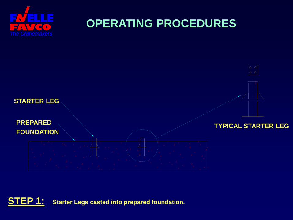
OPERATING PROCEDURES
STEP 1: Starter Legs casted into prepared foundation.
STARTER LEG
PREPARED
FOUNDATION TYPICAL STARTER LEG
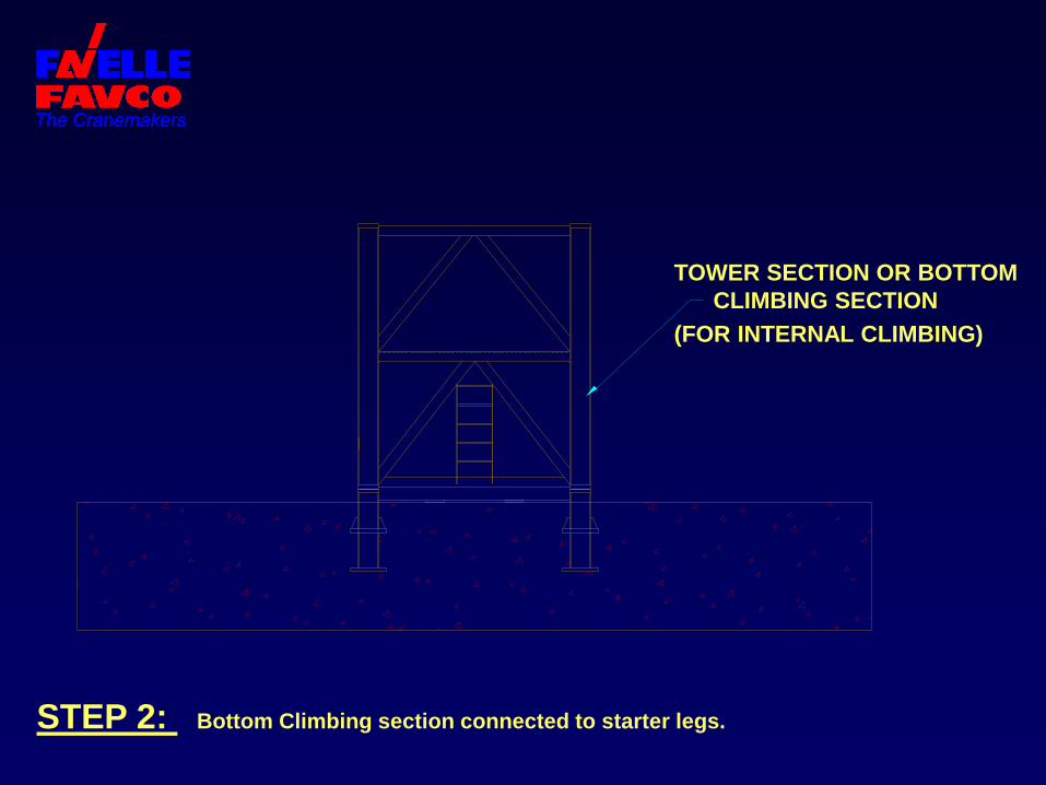
STEP 2: Bottom Climbing section connected to starter legs.
TOWER SECTION OR BOTTOM
CLIMBING SECTION
(FOR INTERNAL CLIMBING)
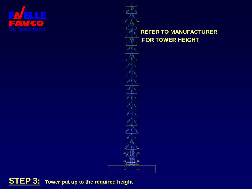
STEP 3: Tower put up to the required height
REFER TO MANUFACTURER
FOR TOWER HEIGHT
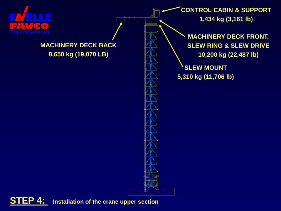
STEP 4: Installation of the crane upper section
MACHINERY DECK BACK
8,650 kg (19,070 LB)
CONTROL CABIN & SUPPORT
1,434 kg (3,161 lb)
MACHINERY DECK FRONT,
SLEW RING & SLEW DRIVE
10,200 kg (22,487 lb)
SLEW MOUNT
5,310 kg (11,706 lb)
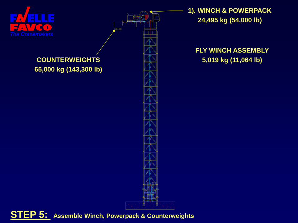
STEP 5: Assemble Winch, Powerpack & Counterweights
COUNTERWEIGHTS
65,000 kg (143,300 lb)
1). WINCH & POWERPACK
24,495 kg (54,000 lb)
FLY WINCH ASSEMBLY
5,019 kg (11,064 lb)
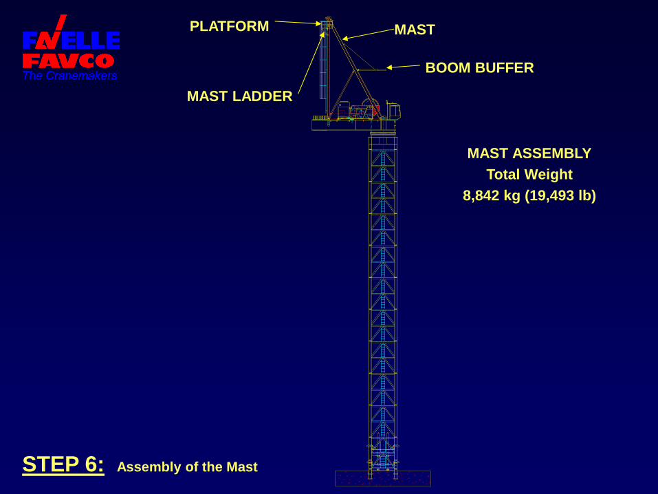
STEP 6: Assembly of the Mast
MAST LADDER
MAST
BOOM BUFFER
MAST ASSEMBLY
Total Weight
8,842 kg (19,493 lb)
PLATFORM
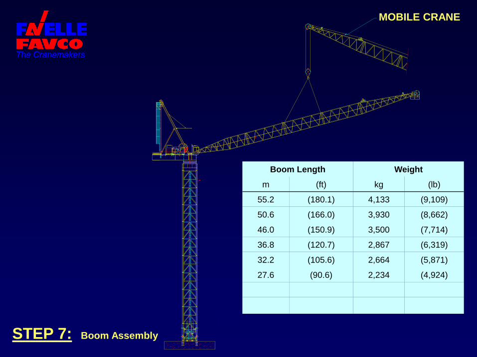
FFC STEP 7: Boom Assembly
Boom Length Weight
m (ft) kg (lb)
55.2 (180.1) 4,133 (9,109)
50.6 (166.0) 3,930 (8,662)
46.0 (150.9) 3,500 (7,714)
36.8 (120.7) 2,867 (6,319)
32.2 (105.6) 2,664 (5,871)
27.6 (90.6) 2,234 (4,924)
MOBILE CRANE
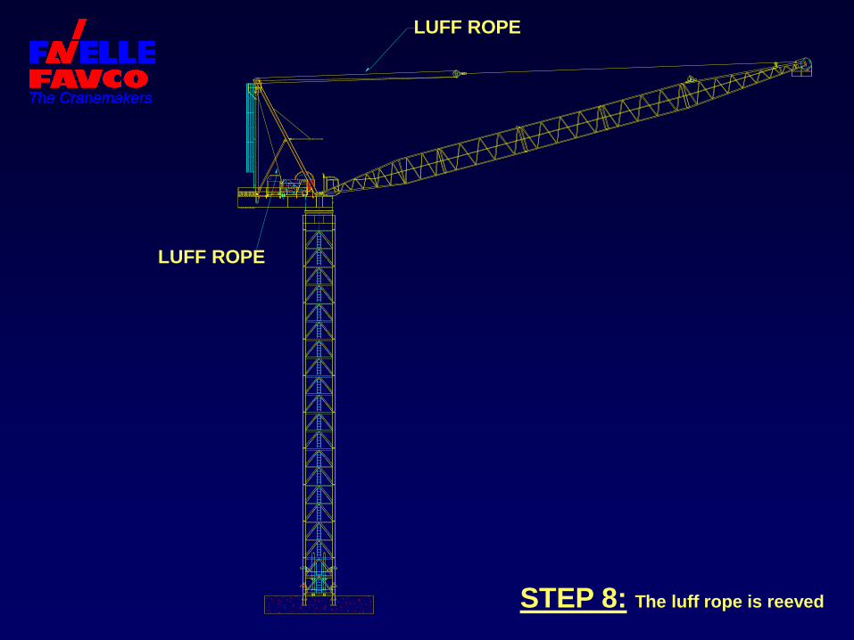
FFC STEP 8: The luff rope is reeved
LUFF ROPE
LUFF ROPE
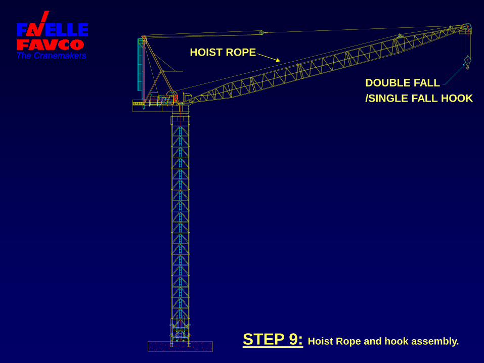
STEP 9: Hoist Rope and hook assembly.
DOUBLE FALL
/SINGLE FALL HOOK
HOIST ROPE
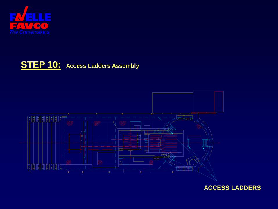
STEP 10: Access Ladders Assembly
ACCESS LADDERS
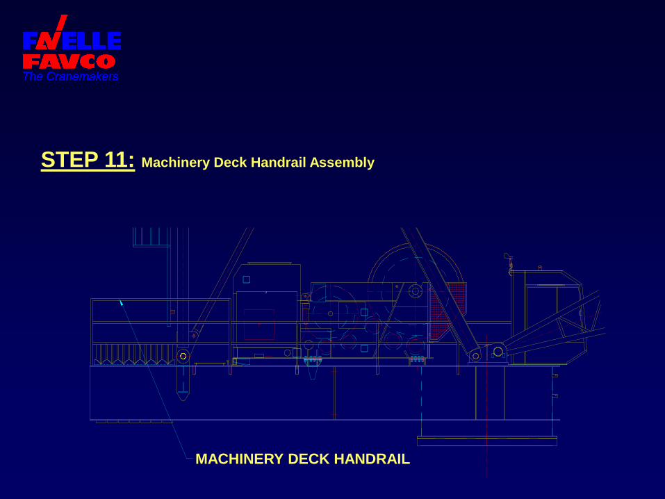
STEP 11: Machinery Deck Handrail Assembly
MACHINERY DECK HANDRAIL
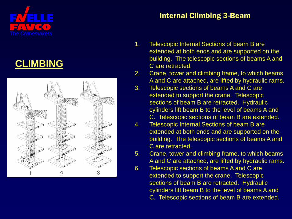
Internal Climbing 3-Beam
CLIMBING
1. Telescopic Internal Sections of beam B are
extended at both ends and are supported on the
building. The telescopic sections of beams A and
C are retracted.
2. Crane, tower and climbing frame, to which beams
A and C are attached, are lifted by hydraulic rams.
3. Telescopic sections of beams A and C are
extended to support the crane. Telescopic
sections of beam B are retracted. Hydraulic
cylinders lift beam B to the level of beams A and
C. Telescopic sections of beam B are extended.
4. Telescopic Internal Sections of beam B are
extended at both ends and are supported on the
building. The telescopic sections of beams A and
C are retracted.
5. Crane, tower and climbing frame, to which beams
A and C are attached, are lifted by hydraulic rams.
6. Telescopic sections of beams A and C are
extended to support the crane. Telescopic
sections of beam B are retracted. Hydraulic
cylinders lift beam B to the level of beams A and
C. Telescopic sections of beam B are extended.
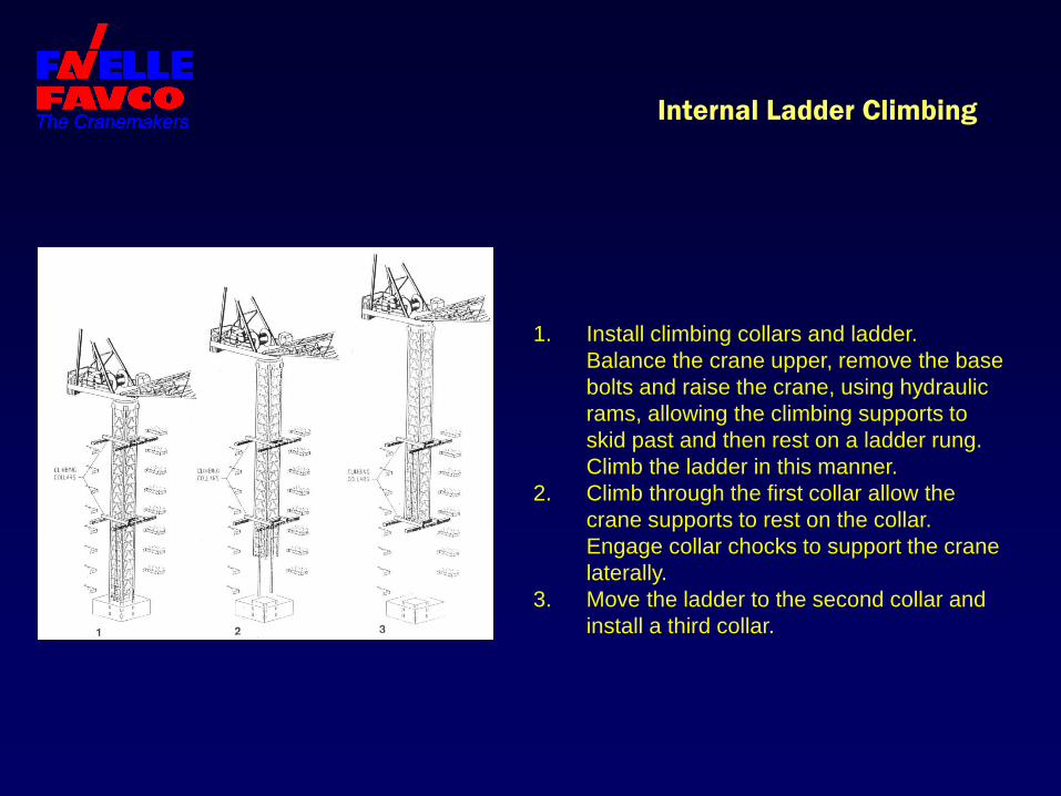
Internal Ladder Climbing
1. Install climbing collars and ladder.
Balance the crane upper, remove the base
bolts and raise the crane, using hydraulic
rams, allowing the climbing supports to
skid past and then rest on a ladder rung.
Climb the ladder in this manner.
2. Climb through the first collar allow the
crane supports to rest on the collar.
Engage collar chocks to support the crane
laterally.
3. Move the ladder to the second collar and
install a third collar.
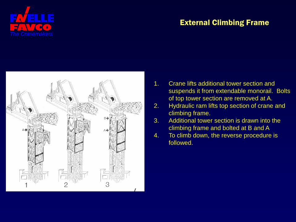
External Climbing Frame
1. Crane lifts additional tower section and
suspends it from extendable monorail. Bolts
of top tower section are removed at A.
2. Hydraulic ram lifts top section of crane and
climbing frame.
3. Additional tower section is drawn into the
climbing frame and bolted at B and A
4. To climb down, the reverse procedure is
followed.
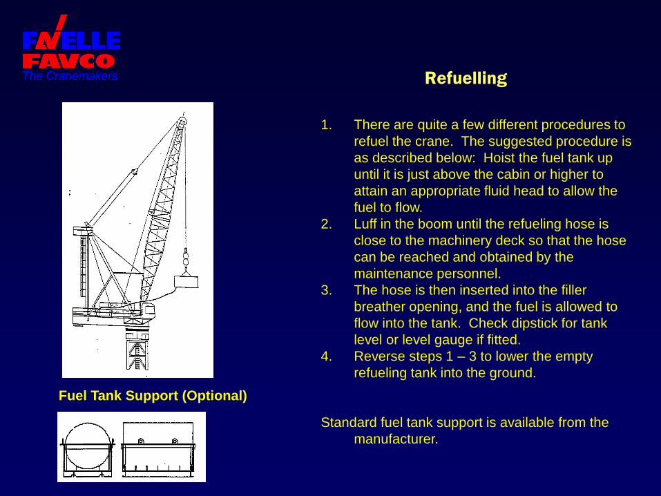
Refuelling
1. There are quite a few different procedures to
refuel the crane. The suggested procedure is
as described below: Hoist the fuel tank up
until it is just above the cabin or higher to
attain an appropriate fluid head to allow the
fuel to flow.
2. Luff in the boom until the refueling hose is
close to the machinery deck so that the hose
can be reached and obtained by the
maintenance personnel.
3. The hose is then inserted into the filler
breather opening, and the fuel is allowed to
flow into the tank. Check dipstick for tank
level or level gauge if fitted.
4. Reverse steps 1 – 3 to lower the empty
refueling tank into the ground.
Standard fuel tank support is available from the
manufacturer.
Fuel Tank Support (Optional)

Favelle Favco Cranes (USA) Inc.
Manufacturing & USA Headquarters 26360 F.M 106
Harlingen Texas 78551 USA
tel: (956) 428-7488 fax: (956) 428-7749
Email: [email protected]
Visit our website at: www.favellefavco.com