Embed Size (px)
Citation preview

Printed in USA 03/09 P/N 129721 rev. E
WARNING . . . Not To Be Used for Personnel Protection
Never use these products as sensing devices for personnel protection. Doing so could lead to serious injury or death.
These sensors do NOT include the self-checking redundant circuitry necessary to allow their use in personnel safety applications. A sensor failure or malfunction can cause either an energized or de-energized sensor output condition. Consult your current Banner Safety Products catalog for safety products which meet OSHA, ANSI and IEC standards for personnel protection.
M12 Series Metal Barrel SensorsRugged, self-contained sensors in a 12 mm threaded barrel
Features
Complete family of sensors, all housed in a compact 12 mm threaded metal barrel•
Opposed, retroreflective, polarized retroreflective, diffuse and 25, 50, or 75 mm cutoff •fixed-field mode operation, depending on model
Excellent background suppression on fixed-field models; an excellent alternative to •proximity sensors
Two Signal indicator LEDs for easy operating status monitoring from any direction•
10 to 30V dc operation•
Complementary solid-state outputs (1 normally open, 1 normally closed); PNP •(sourcing) or NPN (sinking), depending on model
Models
* Only standard 2 m (6.5') cable models are listed. For 9 m (30') cable, add suffix “W/30” to the model number (e.g., M12E W/30). QD models: •4-pinintegralEuro-styleM12connector:addsuffix“Q8” (e.g., M12EQ8). •4-pin150mm(6")Euro-stylepigtail:addsuffix“Q5” (e.g., M12EQ5).
† Retroreflective range is specified using one model BRT-84 retroreflector. Actual sensing range may be more or less than specified, depending upon efficiency and reflective area of the retroreflector(s) used.
Sensing Mode Model* Range Output
Opp
osed
660 nm Visible Red M12E
5 m (16.4')
N/A
M12PR PNP
M12NR NPN
Pola
rized
Re
tro
660 nm Visible Red
M12PLP1.5 m† (4.9')
PNP
M12NLP NPN
Retr
o
660 nm Visible Red
M12PLV2.5 m† (8.2')
PNP
M12NLV NPN
Diffu
se
Performance based on use of 90% reflectance white test card.
660 nm Visible RedM12PD
400mm (15.7")
PNP
M12ND NPN
OPPOSED
PPOLAR RETRO
RETRO
EffectiveBeam:
10mm(0.39")
DIFFUSE
Sensing Mode Model* Range OutputFi
xed-
Fiel
d
Performance based on use of 90% reflectance white test card.
680 nm Visible Red
M12PFF25 25mm(1") cutoff;
25mm(1")focus
PNP
M12NFF25 NPN
M12PFF50 50mm(2") cutoff;
25mm(1")focus
PNP
M12NFF50 NPN
M12PFF75 75mm(3") cutoff;
25mm(1")focus
PNP
M12NFF75 NPN
FIXED-FIELD

Banner Engineering Corp.•Minneapolis,MNU.S.A www.bannerengineering.com•Tel:763.544.31642 P/N 129721 rev. E
M12 Series Metal Barrel Sensors
Overview
Banner’sM12familyofsensorsoffersafullcomplementofsensingmodes,allpackagedinacompact yet rugged metal housing. Their popular 12-mm threaded barrel design allows them to mount easily into tight spaces, with the excellent performance expected of much larger sensors.
The single-turn Gain potentiometer on most models and two Signal LEDs (positioned on either side of the housing for visibility) provide easy alignment and configuration for reliable sensing (see Figure 1). Note that when the signal LED is not ON, the green Power LED is visible through all three LED ports.
Fixed-Field Mode Overview
M12Seriesfixed-fieldsensorsarepowerfuldiffuse-modesensorswithfar-limitcutoff(atypeof background suppression). Their high excess gain and fixed-field technology allow them to detect objects of low reflectivity that are directly in front of another surface, while ignoring the surface in the background.
The cutoff distance is fixed. Backgrounds and background objects must always be placed beyond the cutoff distance.
Fixed-Field Sensing – Theory of OperationInoperation,theM12FFcomparesthereflectionsofitsemittedlightbeam(E)fromanobjectback to the sensor’s two differently-aimed detectors R1 and R2 (see Figure 2). If the near detector (R1) light signal is stronger than the far detector (R2) light signal (see object A, closer than the cutoff distance), the sensor responds to the object. If the far detector (R2) light signal is stronger than the near detector (R1) light signal (see object B, object beyond the cutoff distance), the sensor ignores the object.
ThecutoffdistanceformodelM12FFsensorsisfixedat25,50,or75mm(1",2",or3").Objects lying beyond the cutoff distance are ignored, even if they are highly reflective. However, it is possible to falsely detect a background object, under certain conditions (see Background Reflectivity and Placement).
In the drawings and discussion on these pages, the letters E, R1, and R2 identify how the sensor’s three optical elements (Emitter “E”, Near Detector “R1”, and Far Detector “R2”) line up across the face of the sensor. The location of these elements defines the sensing axis (see Figure 3). The sensing axis becomes important in certain situations, such as those illustrated in Figures 6 and 7.
Fixed-Field Sensor Setup
Sensing ReliabilityFor best sensing reliability, the sensor-to-object distance should be positioned to maximize excess gain. The excess gain curves for these sensors are shown on page 5. Sensing at higher excess gains will make maximum use of the sensor’s available sensing power. The background must be placed beyond the cutoff distance; more reflective backgrounds must be placed further back. Following these two guidelines will improve sensing reliability.
Figure 1. Features
Green ON Steady Power ON
Green Flashing Output overloaded
Yellow ON Steady Light sensed
Yellow Flashing Marginalexcessgain
SensingAxis
R1R2
E
As a general rule, the most reliable sensing of an object approaching from the side occurs when the line of approach is parallel to the sensing axis.
Figure 3. Fixed-field sensing axis
R1
R2
Lenses
ObjectA
Object Bor
Background
SensingRange
CutoffDistance
E
ReceiverElements
NearDetector
FarDetector
Emitter
Object is sensed if amount of light at R1is greater than the amount of light at R2
Figure 2. Fixed-field concept
Power LED
Signal LED (one of two)
Single-turn Gain Potentiometer

P/N 129721 rev. E 3Banner Engineering Corp.•Minneapolis,MNU.S.A
www.bannerengineering.com•Tel:763.544.3164
M12 Series Metal Barrel Sensors
Background Reflectivity and PlacementAvoid mirror-like backgrounds that produce specular reflections. False sensor response will occur if a background surface reflects the sensor’s light more strongly to the near detector, or “sensing” detector (R1) than to the far detector, or “cutoff” detector (R2). The result is a falseONcondition(Figure4).Useofadiffusely-reflective(matte)backgroundwillcurethisproblem. Other possible solutions are to angle the sensor or angle the background (in any plane) so the background does not reflect light back to the sensor (see Figure 5). Position the background as far beyond the cutoff distance as possible.
An object beyond the cutoff distance, either stationary (and when positioned as shown in Figure 6), or if it moves past the face of the sensor in a direction perpendicular to the sensing axis, can cause unwanted triggering of the sensor if it reflects more light to the near detector than to the far detector. The problem is easily remedied by rotating the sensor 90° (Figure 7). The object then reflects the R1 and R2 fields equally, resulting in no false triggering. A better solution, if possible, may be to reposition the object or the sensor.
Color SensitivityThe effects of object reflectivity on cutoff distance, though small, may be important for some applications. It is expected that at any given cutoff setting, the actual cutoff distance for lower reflectance targets will be slightly shorter than for higher reflectance targets. This behavior is known as color sensitivity.
The excess gain curves on page 5 were generated using a white test card of 90% reflectance. Objects with reflectivity of less than 90% reflect less light back to the sensor, and thus require proportionately more excess gain in order to be sensed with the same reliability as more reflective objects. When sensing an object of very low reflectivity, it may be especially important to sense it at or near the distance of maximum excess gain.
E = EmitterR2 = Far DetectorR1 = Near Detector
Core ofEmittedBeam
Cutoff Distance
Reflective Background
StrongDirectReflectionto R1
Fixed Sensing
Field
M12..FF..
R1R2E
FixedSensing
Field
CutoffDistance
ReflectiveBackground
orMoving Object
E = EmitterR2 = Far DetectorR1 = Near Detector
M12..FF..
R1R2E
Figure 4. Reflective background – problem
Figure 5. Reflective background – solution
Figure 6. Object beyond cutoff – problem Figure 7. Object beyond cutoff – solution
M12..FF..
FixedSensing
Field
E = EmitterR2 = Far DetectorR1 = Near Detector
Cutoff Distance
E, R2, R1
ReflectiveBackground
orMoving Object
M12..FF..
E = EmitterR2 = Far DetectorR1 = Near Detector
Core of Emitted Beam
Reflective Background
Fixed Sensing Field
Strong Direct Reflection Away From Sensor
Cutoff Distance
R2R1
E
A reflective background object in this position or moving across the sensor face in this axis and direction may cause false sensor response.
A reflective background object in this position or moving across the sensor face in this axis will be ignored.

Banner Engineering Corp.•Minneapolis,MNU.S.A www.bannerengineering.com•Tel:763.544.31644 P/N 129721 rev. E
M12 Series Metal Barrel Sensors
Sensing Beam Fixed-Field Models: 680 nm visible red All Other Models: 660 nm visible red
Supply Voltage and Current
10 to 30V dc (10% max. ripple) @ 20 mA max current, exclusive of load
Supply Protection Circuitry
Protected against reverse polarity and transient voltages
Output Configuration Complementary (1 normally open and 1 normally closed) solid-state, NPN or PNP, depending on model
Output Ratings 100 mA total across both outputs with overload and short circuit protection OFF-state leakage current: ON-state saturation voltage: NPN: less than 200 µA @ 30V dc (see Application Note 1) NPN: less than 1.6V @ 100 mA PNP: less than 10 µA @ 30V dc PNP: less than 3.0V @ 100 mA
Output Protection Circuitry
Protected against false pulse on power-up, short-circuit protected
Output Response Time Opposed Mode: 625 microseconds ON/375 microseconds OFF All Other Modes: 500 µs ON and OFF NOTE:100msdelayonpower-up;outputsdonotconductduringthistime.
Repeatability Opposed Mode: 85 microseconds All Other Modes: 95 microseconds
Indicators Two Status (yellow) and one Power (green) LED (see Figure 1)
Adjustments Fixed-Field Models: None All Other Models: Single-turn Gain (sensitivity) potentiometer
Construction Housing: Nickel-plated brass Lenses: PMMA Cable Endcap and Gain Potentiometer Adjuster: PBT
Environmental Rating IECIP67;NEMA6,IECIP68and1200PSIWashdown,NEMAICS5AnnexF-2002
Connections 2m(6.5')or9m(30')4-wirePVC-jacketedcable,4-pinintegralEuro-styleQDfitting, or4-pin150mm(6")Euro-stylepigtail,dependingonmodel
Operating Conditions Operating temperature:−20°to+60°C(−4°to+140°F) Relative humidity: 90% max @ +50° C (+122° F) non-condensing
Application Notes 1. NPN off-state leakage current is < 200 μA for load resistances > 3 kΩ or optically isolated loads. For load current of 100 mA, leakage is < 1% of load current
Certifications
Specifications

P/N 129721 rev. E 5Banner Engineering Corp.•Minneapolis,MNU.S.A
www.bannerengineering.com•Tel:763.544.3164
M12 Series Metal Barrel Sensors
Performance Curves
Excess Gain Beam Pattern
Opp
osed
Pola
rized
Ret
ro††
Retr
o††Di
ffuse
Performance based on use of 90% reflectance white test card.
Excess Gain
Fixe
d-Fi
eld
– 25
mm
Performance based on use of 90% reflectance white test card.†
Fixe
d-Fi
eld
– 50
mm
Fixe
d-Fi
eld
– 75
mm
(16")
(16")
(8")
(8")
(24")
(24")
5 m(16')
4 m(13')
3 m(9.8')
2 m(6.6')
1 m(3.3')
0
-200 mm
-400 mm
-600 mm
200 mm
400 mm
600 mm
DISTANCE
Beam
Wid
th
M12Opposed
00
M12Opposed
DISTANCE
1000
10000
10
100
0.1 m(0.3')
1.0 m(3.0')
10.0 m(30.0')
0.01 m(.03')
1
EXCESS
GAIN
††Performance based on use of a model BRT-84 retroreflector.
Focus and spot sizes are typical.
M12Diffuse
DISTANCE
1000
10
100
10 mm(0.4")
100 mm(4.0")
1000 mm(40.0")
1 mm(.04")
1
EXCESS
GAIN
(0.4")
(0.4")
(0.2")
(0.2")
(0.6")
(0.6")
500 mm(20")
400 mm(16")
300 mm(12")
200 mm(8")
100 mm(4")
0
-5 mm
-10 mm
-15 mm
5 mm
10 mm
15 mm
DISTANCE
Beam
Wid
th
M12Diffuse
00
Ø 2 mm spot size @ 25 mm focus Ø 2 mm spot size @ 25 mm cutoff† Using 18% gray test card: cutoff distance
will be 96% of value shown.† Using 6% black test card: cutoff distance
willbe94%ofvalueshown.
(0.8")
(0.8")
(0.4")
(0.4")
(1.2")
(1.2")
(1.6")
(1.6")
2.0 m(6.5')
1.6 m(5.2')
1.2 m(3.9')
0.8 m(2.6')
0.4 m(1.3')
0
-10 mm
-20 mm
-30 mm
-30 mm
10 mm
20 mm
30 mm
40 mm
DISTANCE
Beam
Wid
th
M12Polarized Retro 00
(1.6")
(1.6")
(0.8")
(0.8")
(2.4")
(2.4")
(3.1")
(3.1")
2.5 m(8.2')
2 m(6.6')
1.5 m(4.9')
1 m(3.3')
0.5 m(1.6')
0
-20 mm
-40 mm
-60 mm
-80 mm
20 mm
40 mm
60 mm
80 mm
DISTANCE
Beam
Wid
th
M12Retroreflective 00
Ø 2 mm spot size @ 25 mm focus Ø 7 mm spot size @ 50 mm cutoff† Using 18% gray test card: cutoff distance
will be 90% of value shown.† Using 6% black test card: cutoff distance
will be 85% of value shown.
Ø 2 mm spot size @ 25 mm focus Ø 13 mm spot size @ 75 mm cutoff† Using 18% gray test card: cutoff distance
will be 80% of value shown.† Using 6% black test card: cutoff distance
will be 70% of value shown.
M12Retroreflective
DISTANCE
1000
10
100
0.1 m(0.3')
1 m(3.3')
10 m(33')
0.01 m(0.03')
1
EXCESS
GAIN
M12Polarized Retro
DISTANCE
1000
10
100
0.1 m(0.3')
1 m(3.3')
10 m(33')
0.01 m(0.03')
1
EXCESS
GAIN
M12Fixed Field - 25 mm
DISTANCE
1000
10
100
10 mm(0.4")
100 mm(4.0")
1000 mm(40.0")
1 mm(.04")
1
EXCESS
GAIN
M12Fixed Field - 50 mm
DISTANCE
1000
10
100
10 mm(0.4")
100 mm(4.0")
1000 mm(40.0")
1 mm(.04")
1
EXCESS
GAIN
M12Fixed Field - 75 mm
DISTANCE
1000
10
100
10 mm(0.4")
100 mm(4.0")
1000 mm(40.0")
1 mm(.04")
1
EXCESS
GAIN

Banner Engineering Corp.•Minneapolis,MNU.S.A www.bannerengineering.com•Tel:763.544.31646 P/N 129721 rev. E
M12 Series Metal Barrel Sensors
Dimensions
Emitter
Hookups
Cabled models are shown; QD hookups are functionally identical. (Emitters have no connection to bk and wh.)
74.0 mm(2.91")
43.3 mm(1.70")
34.8 mm(1.37")
M12 X 1
67.5 mm (2.66")
Ø 12.0 mm(0.47")
QD Models Cabled Models
bn
bu
+
–
dc mb-emitter w/cable.eps
10-30V dc
NPN (Current Sinking) Models PNP (Current Sourcing) Models
bn (1)bu (3) -
+
bk (4)wh (2)
Load
Load
Load
Load
10-30V dcbn (1)bu (3)
+
bk (4)wh (2)
Load
Load
10-30V dc–
P/N 129721 rev. E 7Banner Engineering Corp.•Minneapolis,MNU.S.A
www.bannerengineering.com•Tel:763.544.3164
M12 Series Metal Barrel Sensors
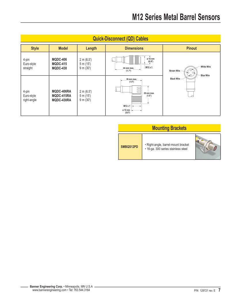
SMBQS12PD•Right-angle,barrel-mountbracket •16-ga.300seriesstainlesssteel
Quick-Disconnect (QD) Cables
Mounting Brackets
Style Model Length Dimensions Pinout
4-pin Euro-style straight
MQDC-406 MQDC-415 MQDC-430
2 m (6.5') 5 m (15') 9 m (30')
4-pin Euro-style right-angle
MQDC-406RA MQDC-415RA MQDC-430RA
2 m (6.5') 5 m (15') 9 m (30')
38 mm max.(1.5")
M12 x 1
ø 15 mm(0.6")
38 mm max.(1.5")
M12 x 1
ø 15 mm(0.6")
44 mm max.(1.7")
White Wire
Blue WireBlack Wire
Brown Wire

M12 Series Metal Barrel Sensors
BannerEngineeringCorp.,9714TenthAve.No.,Minneapolis,MNUSA55441•Phone:763.544.3164•www.bannerengineering.com•Email:[email protected]
P/N 129721 rev. E
Banner Engineering Corp Limited Warranty
Banner Engineering Corp. warrants its products to be free from defects in material and workmanship for one year following the date of shipment. Banner Engineering Corp. will repair or replace, free of charge, any product of its manufacture which, at the time it is returned to the factory, is found to have been defective during the warranty period. This warranty does not cover damage or liability for misuse, abuse, or the improper application or installation of the Banner product.
THIS LIMITED WARRANTY IS EXCLUSIVE AND IN LIEU OF ALL OTHER WARRANTIES WHETHER EXPRESS OR IMPLIED (INCLUDING, WITHOUT LIMITATION, ANY WARRANTY OF MERCHANTABILITY OR FITNESS FOR A PARTICULAR PURPOSE), AND WHETHER ARISING UNDER COURSE OF PERFORMANCE, COURSE OF DEALING OR TRADE USAGE.
This Warranty is exclusive and limited to repair or, at the discretion of Banner Engineering Corp., replacement. IN NO EVENT SHALL BANNER ENGINEERING CORP. BE LIABLE TO BUYER OR ANY OTHER PERSON OR ENTITY FOR ANY EXTRA COSTS, EXPENSES, LOSSES, LOSS OF PROFITS, OR ANY INCIDENTAL, CONSEQUENTIAL OR SPECIAL DAMAGES RESULTING FROM ANY PRODUCT DEFECT OR FROM THE USE OR INABILITY TO USE THE PRODUCT, WHETHER ARISING IN CONTRACT OR WARRANTY, STATUTE, TORT, STRICT LIABILITY, NEGLIGENCE, OR OTHERWISE.
Banner Engineering Corp. reserves the right to change, modify or improve the design of the product without assuming any obligations or liabilities relating to any product previously manufactured by Banner Engineering Corp.