Embed Size (px)
Citation preview
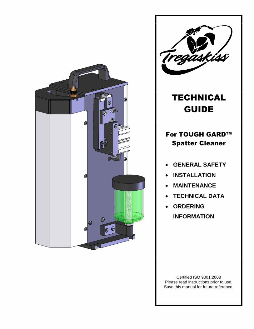
TECHNICAL
GUIDE
For TOUGH GARD™
Spatter Cleaner
GENERAL SAFETY
INSTALLATION
MAINTENANCE
TECHNICAL DATA
ORDERING
INFORMATION
Certified ISO 9001:2008 Please read instructions prior to use. Save this manual for future reference.

2
TABLE OF CONTENTS
WARRANTY ...................................................................................................................................... 2
GENERAL SAFETY .............................................................................................................................. 3
1.0 – INSTALLATION .......................................................................................................................... 6
1.1 TOUGH GARD™ SPATTER CLEANER DIMENSIONS ..................................................................................6
1.2 TOUGH GARD SPATTER CLEANER SETUP ...............................................................................................7
1.3 WIRING INTERFACE ..............................................................................................................................8
1.4 NOZZLE INSERTION HEIGHTS.................................................................................................................9
1.5 V-BLOCK SET-UP ................................................................................................................................. 10
1.6 CUTTER BLADE AND V-BLOCK CHART .................................................................................................. 11
2.0 – MAINTENANCE ....................................................................................................................... 12
3.0 – TECHNICAL DATA .................................................................................................................... 12
3.1 TECHNICAL SPECIFICATIONS ............................................................................................................... 12
3.2 PNEUMATIC DIAGRAM ....................................................................................................................... 13
4.0 – ASSEMBLY VIEW & PARTS LIST ................................................................................................ 14
5.0 – WIRE CUTTER (WC-200) .......................................................................................................... 15
5.1 PARTS LIST AND OPERATION .............................................................................................................. 15
5.2 WIRE CUTTER – BLADE CHANGE / REPLACEMENT ................................................................................ 15
6.0 – ORDERING INFORMATION ...................................................................................................... 16
WARRANTY
Product is warranted to be free from defects in material and workmanship for the period specified below after the sale by an authorized Buyer. Should there be a defect please refer to our Return Merchandise Policy.
PRODUCT WARRANTY PERIOD
TOUGH GUN™ Robotic MIG Guns and Components 180 days
TOUGH GUN Reamer 1 year
TOUGH GARD™ Spatter Cleaner 1 year
TOUGH GUN™ Robotic Peripherals (Clutch, Sprayer, Wire Cutter, Mounting Arms) 1 year
Low-Stress Robotic Unicables (LSR Unicables) 2 years
Tregaskiss reserves the right to repair, replace or refund the purchase price of non-conforming product. Product found not defective will be returned to the Buyer after notification by Customer Service. Tregaskiss makes no other warranty of any kind, expressed or implied, including, but not limited to the warranties of merchantability or fitness for any purpose. Tregaskiss shall not be liable under any circumstances to Buyer, or to any person who shall purchase from Buyer, for damages of any kind, including, but not limited to any, direct, indirect incidental or consequential damages or loss of production or loss of profits resulting from any cause whatsoever, including, but not limited to, any delay, act, error or omission of Tregaskiss. Genuine Tregaskiss parts must be used for safety and performance reasons or the warranty becomes invalid. Warranty shall not apply if accident, abuse, or misuse damages a product, or if a product is modified in any way except by authorized Tregaskiss personnel.

3
GENERAL SAFETY
Before installation or operation of the Tregaskiss TOUGH GARD™ Spatter Cleaner, please read and understand all safety precautions listed below. Failure to follow these instructions may result in personal injury or damage to the equipment.
1. Do not remove or deface warning and instruction labels from the unit. 2. Ensure that all equipment in the area is disabled and locked out before setting up, adjusting or conducting
any work. 3. Ensure that electrical and pneumatic power to unit is off before performing maintenance or troubleshooting. 4. Ensure reset button is pressed to reset circuit board logic before doing any maintenance or troubleshooting
with electrical power and or pneumatic power on. 5. Check that electrical and pneumatic connections comply with the codes applicable to your country / state. 6. Keep hands away from unit while in operation. 7. For additional safety information, please refer to the following publications:
a. ANSI STANDARD Z49.1, SAFETY IN WELDING AND CUTTING, American Welding Society, 550 LeJeune Rd. P.O. Box 351040, Miami, FL 33126
b. ANSI STANDARD, SAFETY OR ROBOTS AND ROBOT SYSTEMS, American National Standards Institute, 1430 Broadway, New York, NY 10018
c. NFPA STANDARD 70-1978. NATIONAL ELECTRIC CODE, National Fire Protection Association, 1470 Atlantic Avenue, Boston MA 02210
CALIFORNIA PROPOSITION 65 WARNING
This product, when used for welding or cutting, produces fumes or gases which contain chemicals known to the State of California to cause birth defects and, in some cases, cancer. This product contains chemicals, including lead, known to the State of California to cause cancer, and birth defects or other reproductive harm. Wash hands after use.
(California Health & Safety Code Section 25249.5 at seq.)

4
PRODUCT-SPECIFIC SAFETY INFORMATION
Read all safety messages throughout this manual.
Obey all safety messages to avoid injury.
Note all safety warnings on product.
Disconnect power before performing any maintenance on this product.
WARNING!
CUT AND CRUSH HAZARD.
Keep hands clear of all moving parts. Disconnect power to wire cutter before
servicing.
WARNING!
ROTATING CUTTER
Keep hands clear. Disconnect power before servicing.
WARNING!
AUTOMATIC START
Equipment starts automatically. Disconnect power before servicing or opening access door.
DISCONNECT POWER BEFORE SERVICING.
CONSULT YOUR SERVICE MANUAL BEFORE
SERVICING.

5
SAFETY STICKER REORDERING INFORMATION
To replace your safety stickers, please call Clarion toll-free at 877-748-0244 (Canada or USA) or 570-296-5686 for international callers. Clarion website: www.clarionsafety.com
STICKER IMAGE STICKER LOCATION CLARION
REORDER #
On side of aluminum cover on wire cutter C21616-01
By power cord on back shroud C21616-02
Above cutter blade on top of unit C21616-03

6
1.0 – INSTALLATION
1.1 TOUGH GARD™ SPATTER CLEANER DIMENSIONS
7
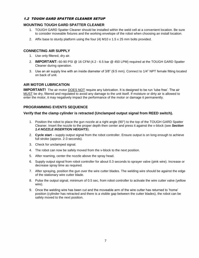
1.2 TOUGH GARD SPATTER CLEANER SETUP
MOUNTING TOUGH GARD SPATTER CLEANER
1. TOUGH GARD Spatter Cleaner should be installed within the weld cell at a convenient location. Be sure to consider moveable fixtures and the working envelope of the robot when choosing an install location.
2. Affix base to sturdy platform using the four (4) M10 x 1.5 x 25 mm bolts provided.
CONNECTING AIR SUPPLY
1. Use only filtered, dry air.
2. IMPORTANT: 60-90 PSI @ 16 CFM (4.2 - 6.5 bar @ 450 LPM) required at the TOUGH GARD Spatter
Cleaner during operation.
3. Use an air supply line with an inside diameter of 3/8” (9.5 mm). Connect to 1/4” NPT female fitting located on back of unit.
AIR MOTOR LUBRICATION
IMPORTANT! The air motor DOES NOT require any lubrication. It is designed to be run ‘lube free’. The air
MUST be dry, filtered and regulated to avoid any damage to the unit itself. If moisture or dirty air is allowed to enter the motor, it may negatively impact the performance of the motor or damage it permanently.
PROGRAMMING EVENTS SEQUENCE
Verify that the clamp cylinder is retracted (Unclamped output signal from REED switch).
1. Position the robot to place the gun nozzle at a right angle (90°) to the top of the TOUGH GARD Spatter
Cleaner. Insert the nozzle to the proper depth then center and press it against the v-block (see Section 1.4 NOZZLE INSERTION HEIGHTS).
2. Cycle start – supply output signal from the robot controller. Ensure output is on long enough to achieve full stroke (approx. 2-3 seconds).
3. Check for unclamped signal.
4. The robot can now be safely moved from the v-block to the next position.
5. After reaming, center the nozzle above the spray head.
6. Supply output signal from robot controller for about 0.3 seconds to sprayer valve (pink wire). Increase or decrease spray time as required.
7. After spraying, position the gun over the wire cutter blades. The welding wire should be against the edge of the stationary wire cutter blade.
8. Pulse the output signal, minimum of 0.5 sec, from robot controller to activate the wire cutter valve (yellow wire).
9. Once the welding wire has been cut and the moveable arm of the wire cutter has returned to ‘home’ position (cylinder has retracted and there is a visible gap between the cutter blades), the robot can be safely moved to the next position.

8
1.3 WIRING INTERFACE
NOTE:
This wiring interface is set up for “sourcing” I/O.
For “sinking” I/O, reverse the polarity of pins 4, 6, 8 and 2.
Reed Switch is polarity sensitive (pins 1 and 7).

9
1.4 NOZZLE INSERTION HEIGHTS
INSERTION DEPTHS
CUTTER NOZZLE
BORE SIZE
RETAINING HEAD
404-3 404-20 / 404-26 404-30 / 404-32
454-1
C-625 5/8" Flush Flush Flush
C-500 1/2" Flush Flush Flush

10
1.5 V-BLOCK SET-UP
IMPORTANT: Ensure that the v-block alignment face is correct for the diameter of the nozzle being used (see
Reference Chart on page 10). DO NOT attempt to use TOUGH GARD Spatter Cleaner until nozzle diameter and v-block position have been verified.
Loosen shoulder screw to adjust v-block orientation
Nozzle diameter indicator

11
1.6 CUTTER BLADE AND V-BLOCK CHART
NOZZLE PART # NOZZLE OUTSIDE DIAMETER CUTTER BLADE PART #
401-4-50 0.938" / 23.83 mm C-500
401-6-50 1.060” / 26.97 mm C-500
401-42-50 0.938" / 23.83 mm C-500
401-44-50 0.938" / 23.83 mm C-500
401-45-50 0.938" / 23.83 mm C-500
401-46-50 0.938" / 23.83 mm C-500
401-47-50 0.938" / 23.83 mm C-500
401-48-50 0.938" / 23.83 mm C-500
401-4-62 0.938" / 23.83 mm C-625
401-5-62 1.060” / 26.97 mm C-625
401-6-62 1.060” / 26.97 mm C-625
401-7-62 1.106" / 28.09 mm C-625
401-8-62 1.106” / 28.09 mm C-625
401-9-62 0.938" / 23.83 mm C-625
401-45-62 0.938" / 23.83 mm C-625
401-46-62 0.938" / 23.83 mm C-625
401-48-62 1.060” / 26.97 mm C-625
401-72-62 1.060” / 26.97 mm C-625
401-81-62 1.060” / 26.97 mm C-625
401-87-62 1.060” / 26.97 mm C-625

12
2.0 – MAINTENANCE
3.0 – TECHNICAL DATA
3.1 TECHNICAL SPECIFICATIONS
I/O Requirements
Controller Sourcing
Controller Sinking
24VDC 24 VDC Unclamped signal to REED switch
0 VDC 0VDC Input – Unclamped “HOME” signal from REED switch
24VDC 0 VDC Output – Cleaning cycle “START” signal
24VDC 0 VDC Output – Sprayer signal
24VDC 0 VDC Output – Wire cutter signal
0VDC 24VDC Common
Rated Voltage 24 VDC
Operating Voltage ±10% of rated voltage
Power Consumption 0.45 W per coil – max. wattage in operation 0.9 W
Air Requirements (minimum) 60 PSI at 6.4 CFM / 4.2 bar at 3 l/s
Air Motor (at min. air requirement )
Stall Torque at 60 PSI = 46 in.-lbs. / 4.3 bar = 5.2 Nm
Cycle Time ~ 2.5 sec
Product Dimensions (L x W x H)
9.9 x 9.6 x 17.6 in. / 252 x 245 x 446 mm
WARNING!
ROTATING CUTTER. AUTOMATIC START.
Keep hands clear of all moving parts. Disconnect power before servicing.

13
3.2 PNEUMATIC DIAGRAM
14
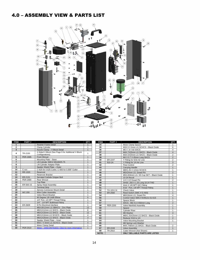
4.0 – ASSEMBLY VIEW & PARTS LIST
ITEM PART # DESCRIPTION QTY
1
Reamer Frame Detail 1
2
Clamp Cylinder 1
3
Nozzle Clamp – V-Block Detail 1
4 TR-2150 4-Sided V-Block (See Page 9 for Additional V-Block Configurations)
1
5 PER-2685 Front Shroud 1
6
Mounting Plate – Base 1
7
Lift Cylinder SMC# MGQM25-75 1
8
Lift Cylinder Adaptor Plate 1
9
Spatter Shield Plate – Outer 1
10 C-xxx C-625 for 0.625 Cutter; C-500 for 0.500” Cutter 1
11 RR-1320 Reservoir 1
12
Reservoir Bracket 1
13 ER-2131 Serrated Carbide Gripper Bolt 1
14 PER-2680 Rear Shroud 1
15 Top Plate 1
16 ER-500-15 Spray Head Assembly 1
17 Terminal Strip 1
18
Service Connector Mount Detail 1
19 WC-200 Wire Cutter Assembly 1
20 Valve Mount Bracket 1
21
90 Degree 1/8 Unifit Elbow 5
22
1/4" Port, 1/4 NPT Thread Fitting 1
23
1/4" - 1/4 NPT Bulkhead Fitting 1
24 ER-2609 8 Pin Electrical Interface 1
25 M5X.8X12mm LG SBHCS – Zinc Plate 12
26
M6X1X12mm LG SHCS – Black Oxide 8
27
M6X1X16mm LG SHCS – Black Oxide 12
28
M6X1X16mm LG SCHCS – Black Oxide 4
29
M6X1X25mm LG SHCS – Black Oxide 3
30
Spatter Shield Plate – Inner 1
31 M4X.7 X 6mm LG SCHCS – Black Oxide 4
32 Motor Clamp Detail 1
33 PER-2510 Motor – DISCONTNUED; Click for more information 1
ITEM PART # DESCRIPTION QTY
34 Motor Clamp Spacer 1
35 M3X.5 X 6mm LG SCHCS – Black Oxide 6
36 M5 X .8 X 60 SHCS 4
37
M4X.7X25mm LG SHCS – Black Oxide 4
38
M3X.5X20mm LG SHCS – Black Oxide 2
39
M4 X 0.7 X 45mm Long SHCS 2
40 ER-2247 Y Fitting for 5/16 Air Line 2
41 910-1A Y Fitting for 1/4 Air Line 3
42 Flow Control 2
43
Carrying Handle 1
44
M8X1.25 X 12mm SCHCS 1
45
M5X24mm LG. Dowel Pin 2
46
M5X.8X6mm LG. SS Cup SKT – Black Oxide 1
47
10-24 Recoil 1
48
1/4 X 1/2 Dowel Pin 2
49
SHSS .250 X 1.25 Long 10-24 THD 1
50
4mm X 1/8 NPT Q/C Fitting 1
51
5/16 " Port, 1/8 NPT Thread Fitting 1
52 TG-103-2-6 Check Valve 1
53 ER-2560 Reed Switch (SMC # D-A93) 1
54 M6X16mm LG. Dowel Pin 4
55
Control Valve SMC# NVM121-01-01S 1
56
Spacer Block 1
57
SHCS - M6 X1.0 X50mm Long 2
58 PER-2200 Valve Manifold Assembly 1
59
Spacer 1
60 Cylinder Riser 1
61 M6 Washer 4
62 M8X1.25X25mm LG SHCS – Black Oxide 1
63 Reducer 5/16 to 1/4 2
64 Valve Mounting Bracket 1
65 M8 Spring Lock Washer
66 M4X.7X8mm LG SHCS – Black Oxide 2
67 ER-2249 Valve Assembly 1
68 TR-2910 Cutter Wrench (Not Shown) 1
NOTE: ONLY SELLABLE PARTS ARE LISTED
15
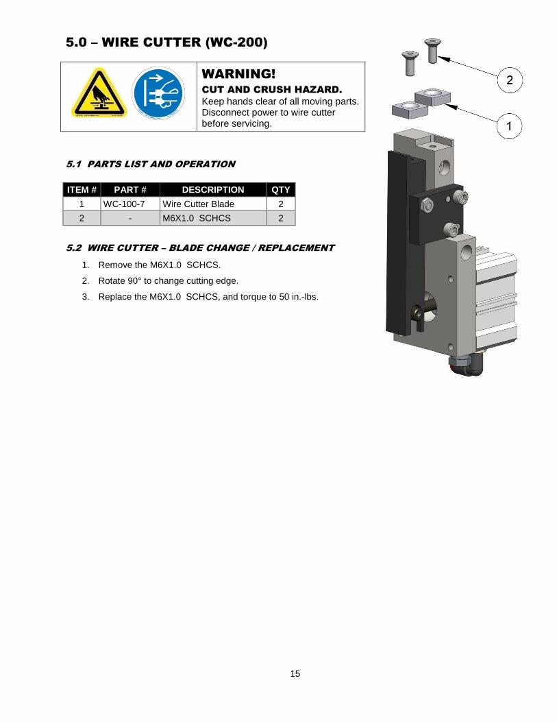
5.0 – WIRE CUTTER (WC-200)
WARNING!
CUT AND CRUSH HAZARD.
Keep hands clear of all moving parts. Disconnect power to wire cutter before servicing.
5.1 PARTS LIST AND OPERATION
5.2 WIRE CUTTER – BLADE CHANGE / REPLACEMENT
1. Remove the M6X1.0 SCHCS.
2. Rotate 90° to change cutting edge.
3. Replace the M6X1.0 SCHCS, and torque to 50 in.-lbs.
ITEM # PART # DESCRIPTION QTY
1 WC-100-7 Wire Cutter Blade 2
2 - M6X1.0 SCHCS 2

16
6.0 – ORDERING INFORMATION
The TOUGH GARD Spatter Cleaner is available in two different models with the following part numbers:
MODEL PART NUMBER
TOUGH GARD Spatter Cleaner for 5/8" Bore Nozzles ER1-625W
TOUGH GARD Spatter Cleaner for 1/2" Bore Nozzles ER1-500W
TOUGH GARD Spatter Cleaner for 3/4" Bore Water-Cooled Nozzles ER1-TG001W
To order a Tregaskiss TOUGH GARD Spatter Cleaner, please contact your local Tregaskiss Sales Representative for more information.
TREGASKISS is an industry leader in the development
and manufacture of robotic MIG welding guns, welding consumables and peripherals.
TREGASKISS™, TOUGH GUN™, TOUGH LOCK™,
and other names are trademarks of Tregaskiss, a division of ITW Canada Inc.
M075 REV K 05/13