Embed Size (px)
Citation preview

Layer 2 Networking Fundamentals
2 – 1Revision 0111
CNE200
Layer 2 Networking Fundamentals
2 – 2Revision 0111
CNE200
Layer 2 Networking Fundamentals
2 – 3Revision 0111
CNE200

Layer 2 Networking Fundamentals
2 – 4Revision 0111
CNE200
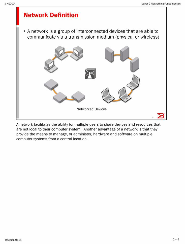
A network facilitates the ability for multiple users to share devices and resources that
are not local to their computer system. Another advantage of a network is that they
provide the means to manage, or administer, hardware and software on multiple
computer systems from a central location.
Layer 2 Networking Fundamentals
2 – 5Revision 0111
CNE200
The three categories do not have formal definitions. Vendors apply the terms loosely to
distinguish among the technologies.
Layer 2 Networking Fundamentals
2 – 6Revision 0111
CNE200
A Local Area Network (LAN) is a computer network covering a small physical area, like a
home, office, or small group of buildings, such as a school, or an airport. The defining
characteristics of LANs, in contrast to wide-area networks (WANs), include their usually
higher data-transfer rates, supporting smaller geographic regions, and lack of a need for
leased telecommunication lines.
A Local Area Network (LAN) will require the basic components categorized as: Hardware
and Software.
Layer 2 Networking Fundamentals
2 – 7Revision 0111
CNE200
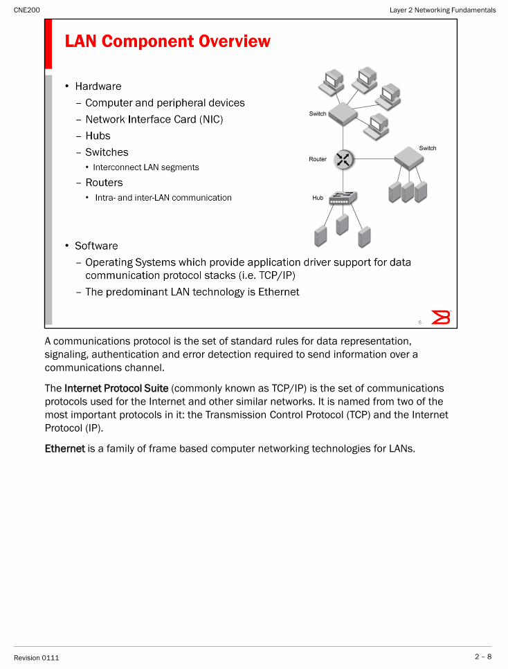
A communications protocol is the set of standard rules for data representation,
signaling, authentication and error detection required to send information over a
communications channel.
The Internet Protocol Suite (commonly known as TCP/IP) is the set of communications
protocols used for the Internet and other similar networks. It is named from two of the
most important protocols in it: the Transmission Control Protocol (TCP) and the Internet
Protocol (IP).
Ethernet is a family of frame based computer networking technologies for LANs.
Layer 2 Networking Fundamentals
2 – 8Revision 0111
CNE200
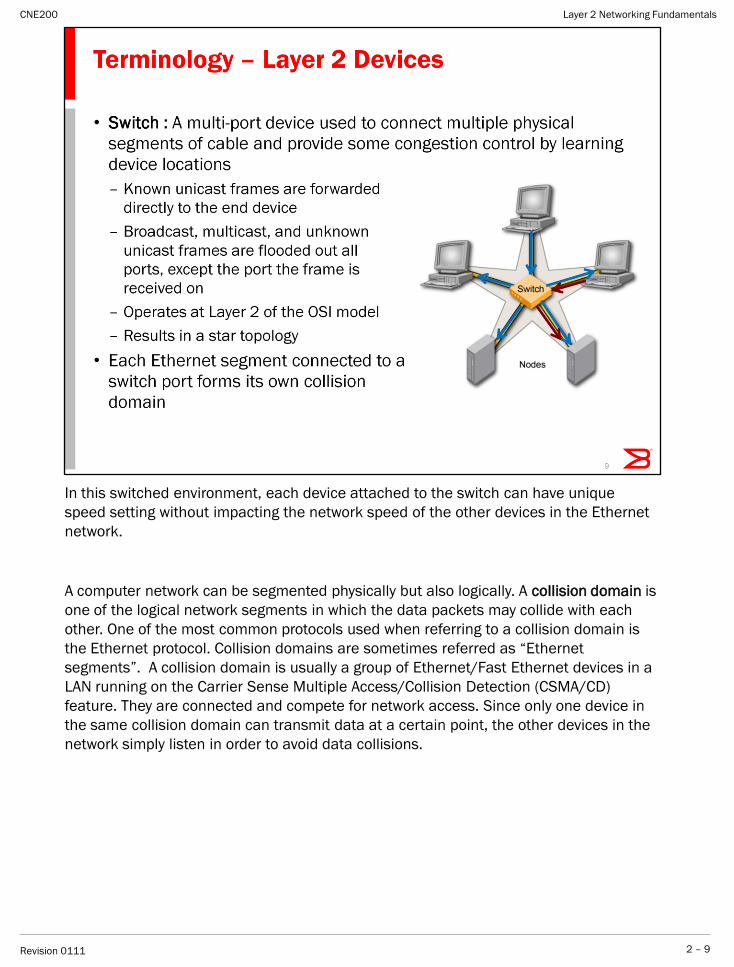
In this switched environment, each device attached to the switch can have unique
speed setting without impacting the network speed of the other devices in the Ethernet
network.
A computer network can be segmented physically but also logically. A collision domain is
one of the logical network segments in which the data packets may collide with each
other. One of the most common protocols used when referring to a collision domain is
the Ethernet protocol. Collision domains are sometimes referred as ―Ethernet
segments‖. A collision domain is usually a group of Ethernet/Fast Ethernet devices in a
LAN running on the Carrier Sense Multiple Access/Collision Detection (CSMA/CD)
feature. They are connected and compete for network access. Since only one device in
the same collision domain can transmit data at a certain point, the other devices in the
network simply listen in order to avoid data collisions.
Layer 2 Networking Fundamentals
2 – 9Revision 0111
CNE200
Layer 2 Networking Fundamentals
2 – 10Revision 0111
CNE200
Layer 2 Networking Fundamentals
2 – 11Revision 0111
CNE200
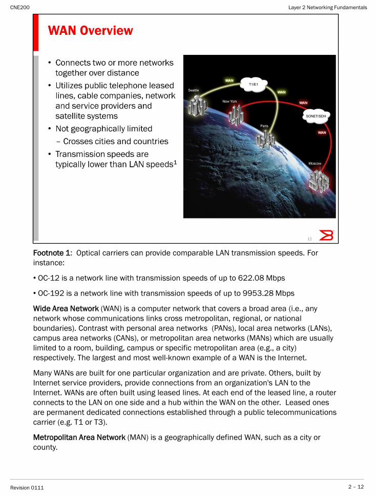
Footnote 1: Optical carriers can provide comparable LAN transmission speeds. For
instance:
• OC-12 is a network line with transmission speeds of up to 622.08 Mbps
• OC-192 is a network line with transmission speeds of up to 9953.28 Mbps
Wide Area Network (WAN) is a computer network that covers a broad area (i.e., any
network whose communications links cross metropolitan, regional, or national
boundaries). Contrast with personal area networks (PANs), local area networks (LANs),
campus area networks (CANs), or metropolitan area networks (MANs) which are usually
limited to a room, building, campus or specific metropolitan area (e.g., a city)
respectively. The largest and most well-known example of a WAN is the Internet.
Many WANs are built for one particular organization and are private. Others, built by
Internet service providers, provide connections from an organization's LAN to the
Internet. WANs are often built using leased lines. At each end of the leased line, a router
connects to the LAN on one side and a hub within the WAN on the other. Leased ones
are permanent dedicated connections established through a public telecommunications
carrier (e.g. T1 or T3).
Metropolitan Area Network (MAN) is a geographically defined WAN, such as a city or
county.
Layer 2 Networking Fundamentals
2 – 12Revision 0111
CNE200
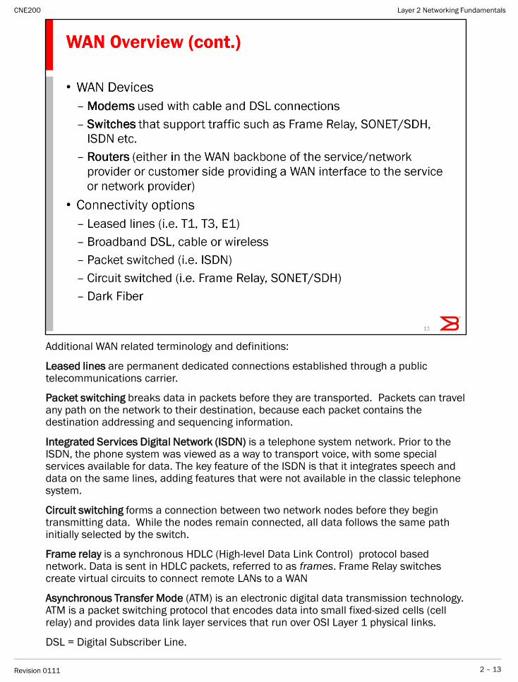
Additional WAN related terminology and definitions:
Leased lines are permanent dedicated connections established through a public telecommunications carrier.
Packet switching breaks data in packets before they are transported. Packets can travel any path on the network to their destination, because each packet contains the destination addressing and sequencing information.
Integrated Services Digital Network (ISDN) is a telephone system network. Prior to the ISDN, the phone system was viewed as a way to transport voice, with some special services available for data. The key feature of the ISDN is that it integrates speech and data on the same lines, adding features that were not available in the classic telephone system.
Circuit switching forms a connection between two network nodes before they begin transmitting data. While the nodes remain connected, all data follows the same path initially selected by the switch.
Frame relay is a synchronous HDLC (High-level Data Link Control) protocol based network. Data is sent in HDLC packets, referred to as frames. Frame Relay switches create virtual circuits to connect remote LANs to a WAN
Asynchronous Transfer Mode (ATM) is an electronic digital data transmission technology. ATM is a packet switching protocol that encodes data into small fixed-sized cells (cell relay) and provides data link layer services that run over OSI Layer 1 physical links.
DSL = Digital Subscriber Line.
Layer 2 Networking Fundamentals
2 – 13Revision 0111
CNE200
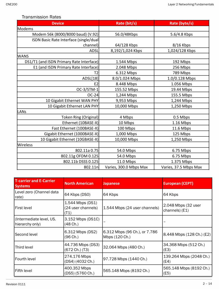
Transmission Rates
T-carrier and E-Carrier Systems
North American Japanese European (CEPT)
Level zero (Channel data
rate)64 Kbps (DS0) 64 Kbps 64 Kbps
First level
1.544 Mbps (DS1)
(24 user channels)
(T1)
1.544 Mbps (24 user channels)2.048 Mbps (32 user
channels) (E1)
(Intermediate level, US.
hierarchy only)
3.152 Mbps (DS1C)
(48 Ch.)– –
Second level6.312 Mbps (DS2)
(96 Ch.)
6.312 Mbps (96 Ch.), or 7.786
Mbps (120 Ch.)8.448 Mbps (128 Ch.) (E2)
Third level44.736 Mbps (DS3)
(672 Ch.) (T3)32.064 Mbps (480 Ch.)
34.368 Mbps (512 Ch.)
(E3)
Fourth level274.176 Mbps
(DS4) (4032 Ch.)97.728 Mbps (1440 Ch.)
139.264 Mbps (2048 Ch.)
(E4)
Fifth level400.352 Mbps
(DS5) (5760 Ch.)565.148 Mbps (8192 Ch.)
565.148 Mbps (8192 Ch.)
(E5)
Device Rate (bit/s) Rate (byte/s)
Modems
Modem 56k (8000/8000 baud) (V.92) 56.0/48Kbps 5.6/4.8 Kbps
ISDN Basic Rate Interface (single/dual channel) 64/128 Kbps 8/16 Kbps
ADSL 8,192/1,024 Kbps 1,024/128 Kbps
WANS
DS1/T1 (and ISDN Primary Rate Interface) 1.544 Mbps 192 Mbps
E1 (and ISDN Primary Rate Interface) 2.048 Mbps 256 Mbps
T2 6.312 Mbps 789 Mbps
ADSL[18] 8.0/1.024 Mbps 1.0/0.128 Mbps
E2 8.448 Mbps 1.056 Mbps
OC-3/STM-1 155.52 Mbps 19.44 Mbps
OC-24 1,244 Mbps 155.5 Mbps
10 Gigabit Ethernet WAN PHY 9,953 Mbps 1,244 Mbps
10 Gigabit Ethernet LAN PHY 10,000 Mbps 1,250 Mbps
LANs
Token Ring (Original) 4 Mbps 0.5 Mbps
Ethernet (10BASE-X) 10 Mbps 1.16 Mbps
Fast Ethernet (100BASE-X) 100 Mbps 11.6 Mbps
Gigabit Ethernet (1000BASE-X) 1,000 Mbps 125 Mbps
10 Gigabit Ethernet (10GBASE-X) 10,000 Mbps 1,250 Mbps
Wireless
802.11a 0.75 54.0 Mbps 6.75 Mbps
802.11g OFDM 0.125 54.0 Mbps 6.75 Mbps
802.11b DSSS 0.125 11.0 Mbps 1.375 Mbps
802.11n Varies, 300.0 Mbps Max Varies, 37.5 Mbps Max
Layer 2 Networking Fundamentals
2 – 14Revision 0111
CNE200
MAN Overview:
•Optimized for a larger geographical area than a LAN, ranging from several blocks of
buildings to entire cities
•Typically supports moderate-to-high data rates
•May be owned and operated by a single organization, but is usually used by many
individuals and organizations or is operated as a public utility
•Provides a means for internetworking of local networks.
•Can span a range of 50 km
A Metropolitan Area Network (MAN) is a large computer network that spans a
metropolitan area or campus. Its geographic scope falls between a WAN and LAN.
MANs provide Internet connectivity for LANs in a metropolitan region, and connect
them to wider area networks like the Internet.
Layer 2 Networking Fundamentals
2 – 15Revision 0111
CNE200

Layer 2 Networking Fundamentals
2 – 16Revision 0111
CNE200
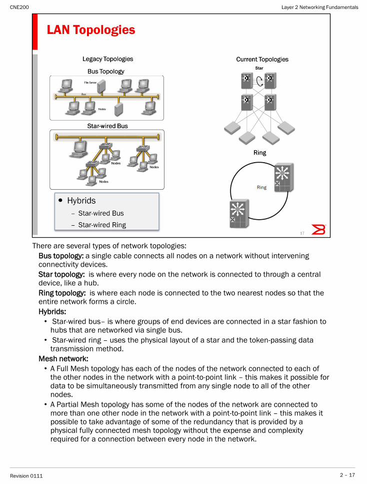
There are several types of network topologies:
Bus topology: a single cable connects all nodes on a network without intervening connectivity devices.
Star topology: is where every node on the network is connected to through a central device, like a hub.
Ring topology: is where each node is connected to the two nearest nodes so that the entire network forms a circle.
Hybrids:
• Star-wired bus– is where groups of end devices are connected in a star fashion to hubs that are networked via single bus.
• Star-wired ring – uses the physical layout of a star and the token-passing data transmission method.
Mesh network:
• A Full Mesh topology has each of the nodes of the network connected to each of the other nodes in the network with a point-to-point link – this makes it possible for data to be simultaneously transmitted from any single node to all of the other nodes.
• A Partial Mesh topology has some of the nodes of the network are connected to more than one other node in the network with a point-to-point link – this makes it possible to take advantage of some of the redundancy that is provided by a physical fully connected mesh topology without the expense and complexity required for a connection between every node in the network.
Layer 2 Networking Fundamentals
2 – 17Revision 0111
CNE200
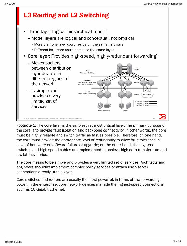
Footnote 1: The core layer is the simplest yet most critical layer. The primary purpose of
the core is to provide fault isolation and backbone connectivity; in other words, the core
must be highly reliable and switch traffic as fast as possible. Therefore, on one hand,
the core must provide the appropriate level of redundancy to allow fault tolerance in
case of hardware or software failure or upgrade; on the other hand, the high-end
switches and high-speed cables are implemented to achieve high data transfer rate and
low latency period.
The core means to be simple and provides a very limited set of services. Architects and
engineers shouldn't implement complex policy services or attach user/server
connections directly at this layer.
Core switches and routers are usually the most powerful, in terms of raw forwarding
power, in the enterprise; core network devices manage the highest-speed connections,
such as 10 Gigabit Ethernet.
Layer 2 Networking Fundamentals
2 – 18Revision 0111
CNE200
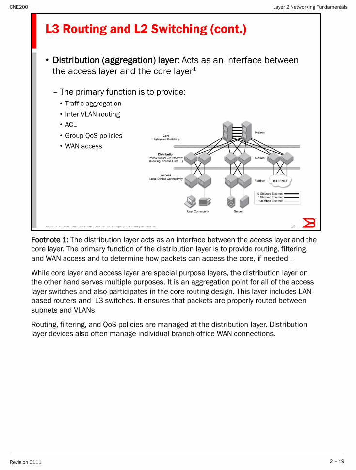
Footnote 1: The distribution layer acts as an interface between the access layer and the
core layer. The primary function of the distribution layer is to provide routing, filtering,
and WAN access and to determine how packets can access the core, if needed .
While core layer and access layer are special purpose layers, the distribution layer on
the other hand serves multiple purposes. It is an aggregation point for all of the access
layer switches and also participates in the core routing design. This layer includes LAN-
based routers and L3 switches. It ensures that packets are properly routed between
subnets and VLANs
Routing, filtering, and QoS policies are managed at the distribution layer. Distribution
layer devices also often manage individual branch-office WAN connections.
Layer 2 Networking Fundamentals
2 – 19Revision 0111
CNE200
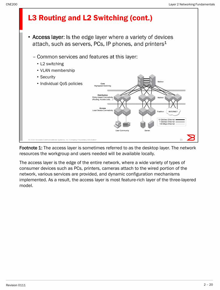
Footnote 1: The access layer is sometimes referred to as the desktop layer. The network
resources the workgroup and users needed will be available locally.
The access layer is the edge of the entire network, where a wide variety of types of
consumer devices such as PCs, printers, cameras attach to the wired portion of the
network, various services are provided, and dynamic configuration mechanisms
implemented. As a result, the access layer is most feature-rich layer of the three-layered
model.
Layer 2 Networking Fundamentals
2 – 20Revision 0111
CNE200
Layer 2 Networking Fundamentals
2 – 21Revision 0111
CNE200
Layer 2 Networking Fundamentals
2 – 22Revision 0111
CNE200
Internetworking Standards Organizations
A wide variety of organizations contribute to internetworking standards by providing forums for
discussion, turning informal discussion into formal specifications, and proliferating
specifications after they are standardized.
Most standards organizations create formal standards by using specific processes: organizing
ideas, discussing the approach, developing draft standards, voting on all or certain aspects of
the standards, and then formally releasing the completed standard to the public.
Some of the best-known standards organizations that contribute to internetworking standards
include these:
International Organization for Standardization (ISO) is an international standards organization
responsible for a wide range of standards. Its best-known contribution is the development of the
OSI reference model and the OSI protocol suite.
American National Standards Institute (ANSI), which is also a member of the ISO, developed the
Fiber Distributed Data Interface (FDDI) and other communications standards.
Electronic Industries Association (EIA)—EIA specifies electrical transmission standards, including
those used in networking. The EIA developed the widely used EIA/TIA-232 standard (formerly
known as RS-232).
Layer 2 Networking Fundamentals
2 – 23Revision 0111
CNE200
IEEE, Institute of Electrical and Electronics Engineers is one of the leading standards--
making organizations in the world. IEEE standards affect a wide range of industries
including: power and energy, biomedical and healthcare, Information Technology (IT),
telecommunications, transportation, nanotechnology, information assurance, and
many more. In 2005, IEEE had close to 900 active standards, with 500 standards
under development. One of the more notable IEEE standards is the IEEE 802 LAN/MAN
group of standards which includes the IEEE 802.3 Ethernet standard and the IEEE
802.11 Wireless Networking standard.
IETF, Internet Engineering Task Force , develops and promotes internet standards,
dealing in particular with standards of the TCP/IP and internet protocol suite. It is an
open standards organization, with no formal membership or membership
requirements.
Layer 2 Networking Fundamentals
2 – 24Revision 0111
CNE200
Layer 2 Networking Fundamentals
2 – 25Revision 0111
CNE200
Layer 2 Networking Fundamentals
2 – 26Revision 0111
CNE200
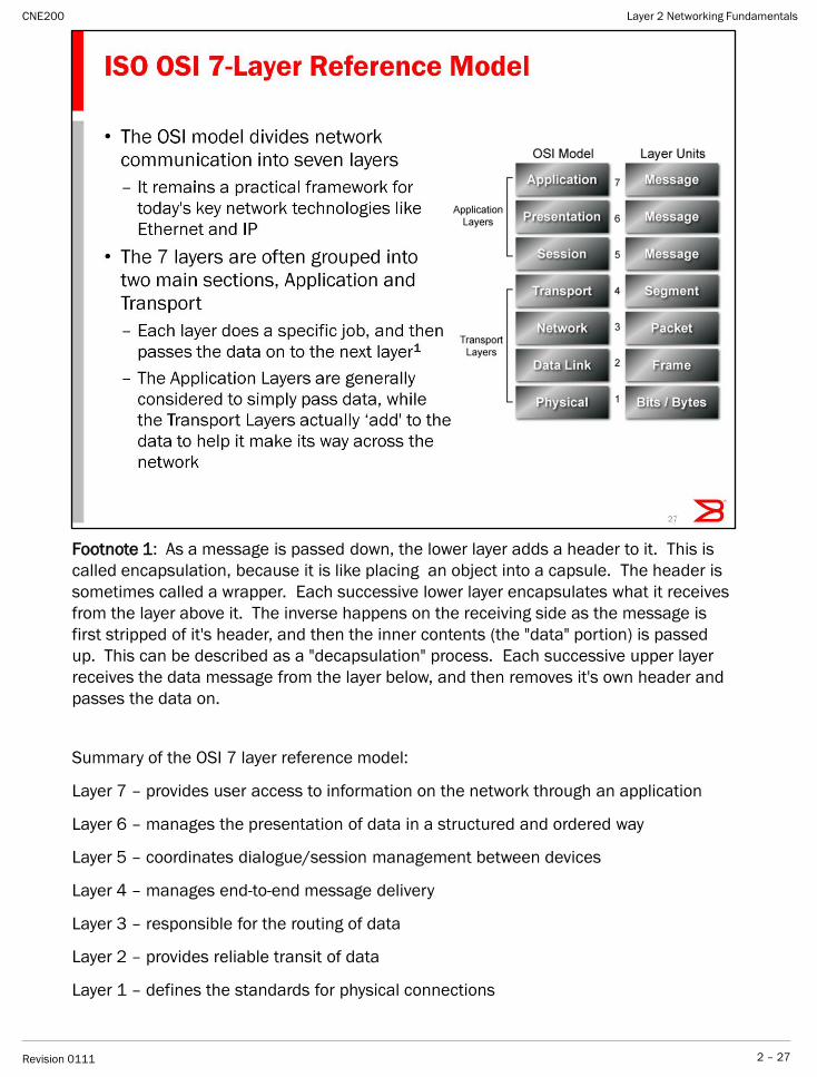
Footnote 1: As a message is passed down, the lower layer adds a header to it. This is
called encapsulation, because it is like placing an object into a capsule. The header is
sometimes called a wrapper. Each successive lower layer encapsulates what it receives
from the layer above it. The inverse happens on the receiving side as the message is
first stripped of it's header, and then the inner contents (the "data" portion) is passed
up. This can be described as a "decapsulation" process. Each successive upper layer
receives the data message from the layer below, and then removes it's own header and
passes the data on.
Summary of the OSI 7 layer reference model:
Layer 7 – provides user access to information on the network through an application
Layer 6 – manages the presentation of data in a structured and ordered way
Layer 5 – coordinates dialogue/session management between devices
Layer 4 – manages end-to-end message delivery
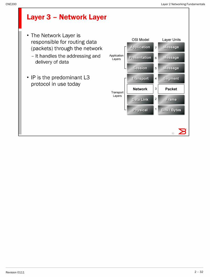
Layer 3 – responsible for the routing of data
Layer 2 – provides reliable transit of data
Layer 1 – defines the standards for physical connections
Layer 2 Networking Fundamentals
2 – 27Revision 0111
CNE200
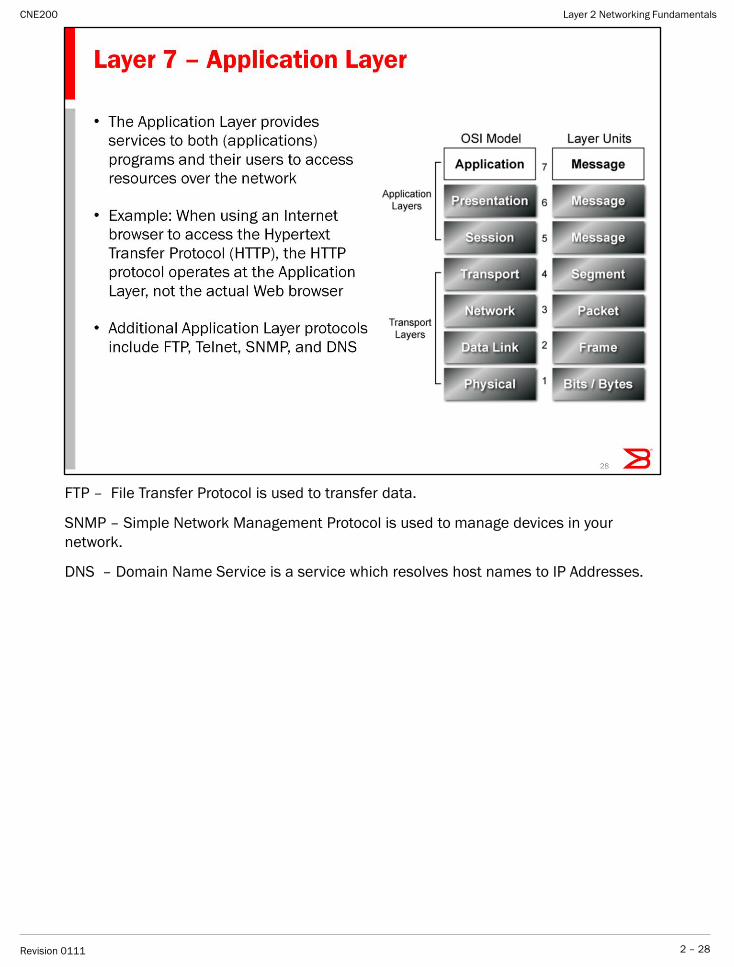
FTP – File Transfer Protocol is used to transfer data.
SNMP – Simple Network Management Protocol is used to manage devices in your
network.
DNS – Domain Name Service is a service which resolves host names to IP Addresses.
Layer 2 Networking Fundamentals
2 – 28Revision 0111
CNE200
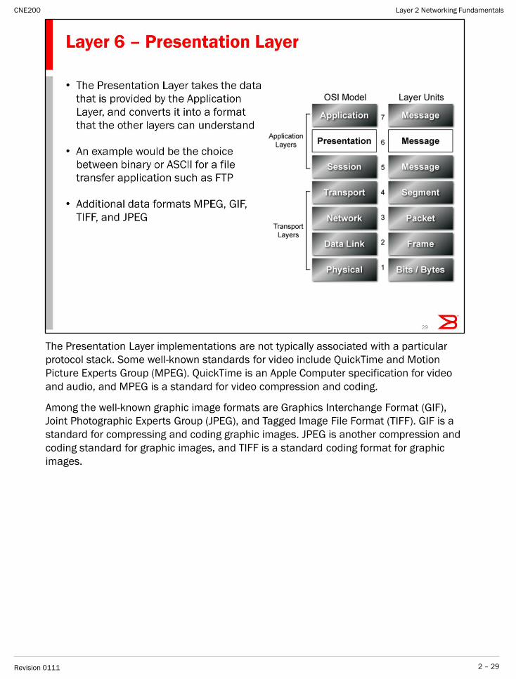
The Presentation Layer implementations are not typically associated with a particular
protocol stack. Some well-known standards for video include QuickTime and Motion
Picture Experts Group (MPEG). QuickTime is an Apple Computer specification for video
and audio, and MPEG is a standard for video compression and coding.
Among the well-known graphic image formats are Graphics Interchange Format (GIF),
Joint Photographic Experts Group (JPEG), and Tagged Image File Format (TIFF). GIF is a
standard for compressing and coding graphic images. JPEG is another compression and
coding standard for graphic images, and TIFF is a standard coding format for graphic
images.
Layer 2 Networking Fundamentals
2 – 29Revision 0111
CNE200
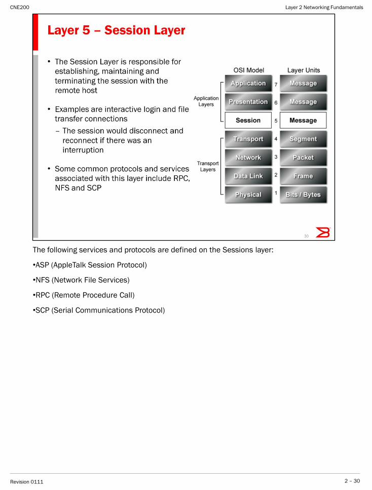
The following services and protocols are defined on the Sessions layer:
•ASP (AppleTalk Session Protocol)
•NFS (Network File Services)
•RPC (Remote Procedure Call)
•SCP (Serial Communications Protocol)
Layer 2 Networking Fundamentals
2 – 30Revision 0111
CNE200
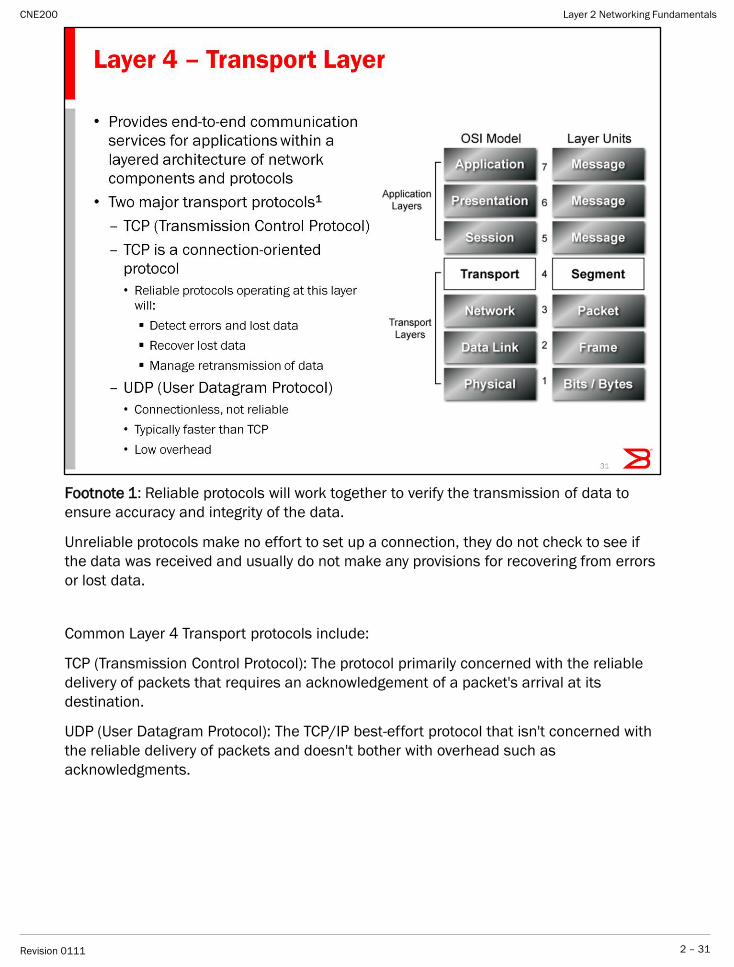
Footnote 1: Reliable protocols will work together to verify the transmission of data to
ensure accuracy and integrity of the data.
Unreliable protocols make no effort to set up a connection, they do not check to see if
the data was received and usually do not make any provisions for recovering from errors
or lost data.
Common Layer 4 Transport protocols include:
TCP (Transmission Control Protocol): The protocol primarily concerned with the reliable
delivery of packets that requires an acknowledgement of a packet's arrival at its
destination.
UDP (User Datagram Protocol): The TCP/IP best-effort protocol that isn't concerned with
the reliable delivery of packets and doesn't bother with overhead such as
acknowledgments.
Layer 2 Networking Fundamentals
2 – 31Revision 0111
CNE200
Layer 2 Networking Fundamentals
2 – 32Revision 0111
CNE200
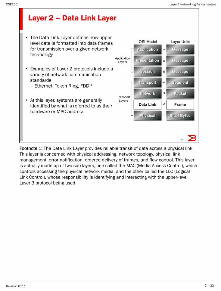
Footnote 1: The Data Link Layer provides reliable transit of data across a physical link.
This layer is concerned with physical addressing, network topology, physical link
management, error notification, ordered delivery of frames, and flow control. This layer
is actually made up of two sub-layers, one called the MAC (Media Access Control), which
controls accessing the physical network media, and the other called the LLC (Logical
Link Control), whose responsibility is identifying and interacting with the upper-level
Layer 3 protocol being used.
Layer 2 Networking Fundamentals
2 – 33Revision 0111
CNE200

Multiple specifications are sometimes used to complete all details of the Physical layer.
For example, RJ-45 defines the shape of the connector and the number of wires or pins
in the cable. Ethernet and the 802.3 standard defines the use of wires or pins 1, 2, 3,
and 6
Layer 2 Networking Fundamentals
2 – 34Revision 0111
CNE200
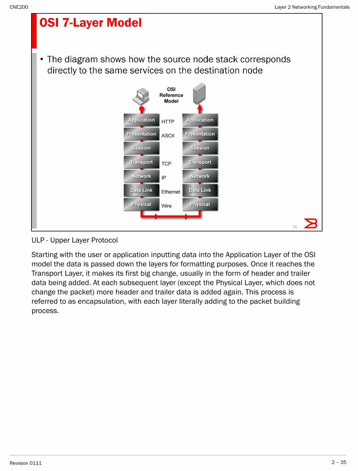
ULP - Upper Layer Protocol
Starting with the user or application inputting data into the Application Layer of the OSI
model the data is passed down the layers for formatting purposes. Once it reaches the
Transport Layer, it makes its first big change, usually in the form of header and trailer
data being added. At each subsequent layer (except the Physical Layer, which does not
change the packet) more header and trailer data is added again. This process is
referred to as encapsulation, with each layer literally adding to the packet building
process.
Layer 2 Networking Fundamentals
2 – 35Revision 0111
CNE200

Layer 2 Networking Fundamentals
2 – 36Revision 0111
CNE200
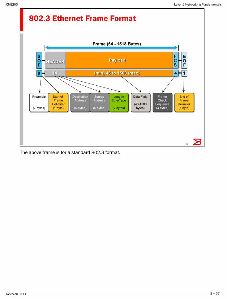
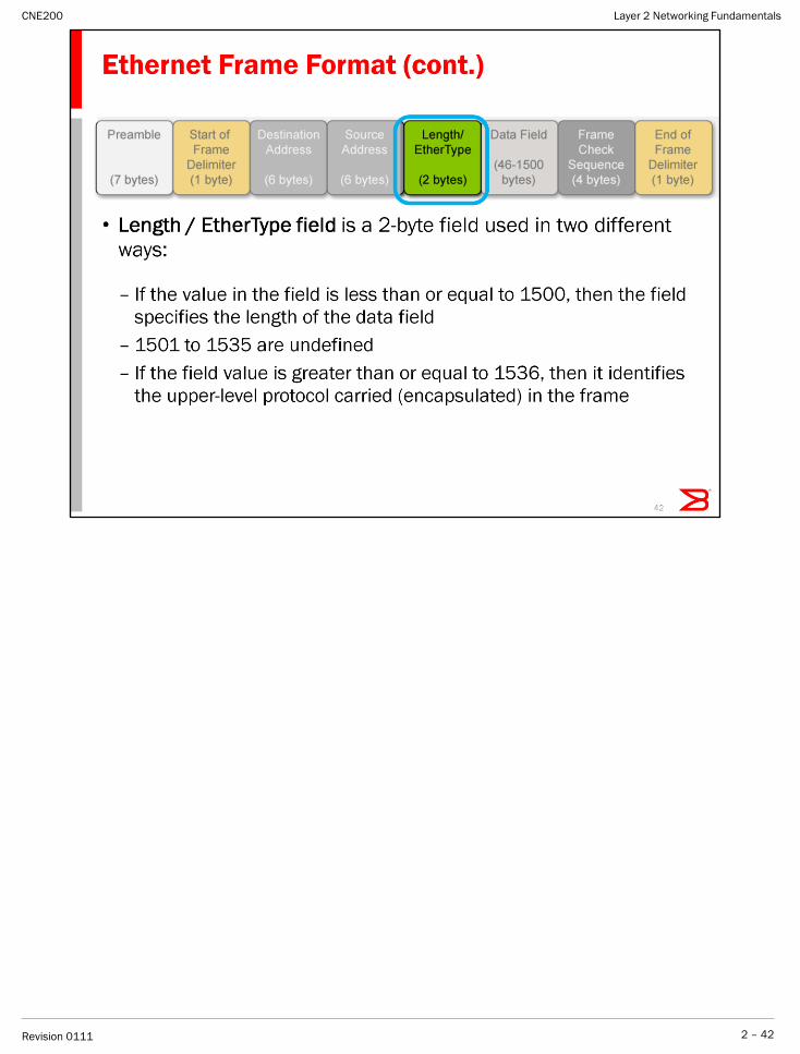
The above frame is for a standard 802.3 format.
Layer 2 Networking Fundamentals
2 – 37Revision 0111
CNE200
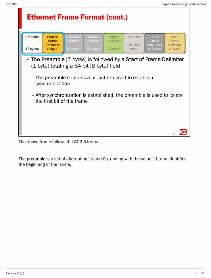
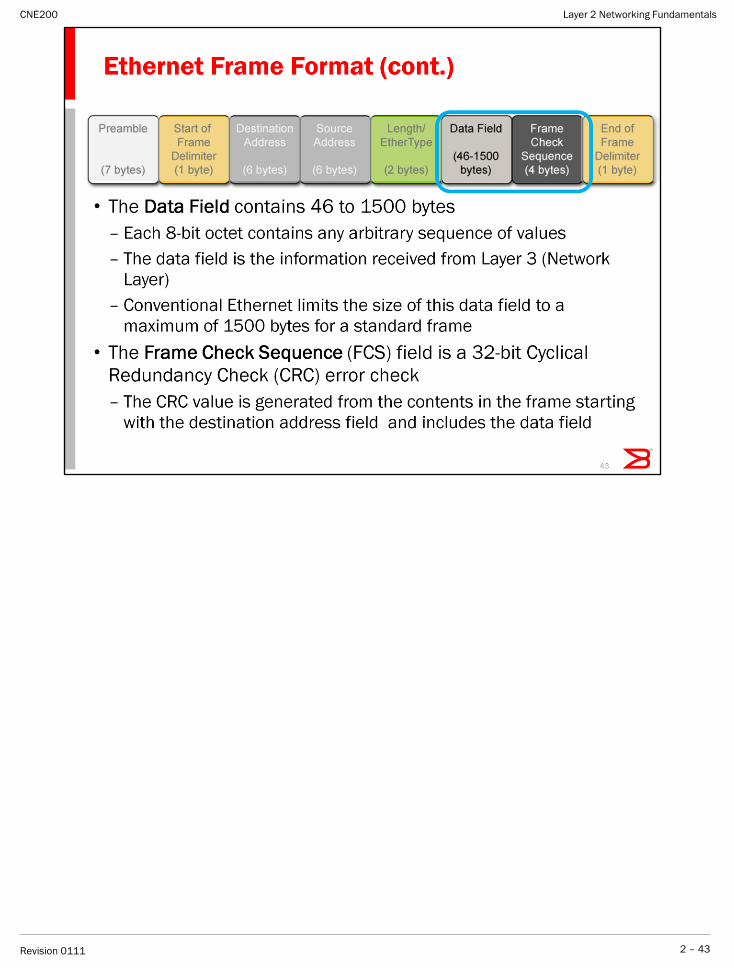
The above frame follows the 802.3 format.
The preamble is a set of alternating 1s and 0s, ending with the value 11, and identifies
the beginning of the frame.
Layer 2 Networking Fundamentals
2 – 38Revision 0111
CNE200
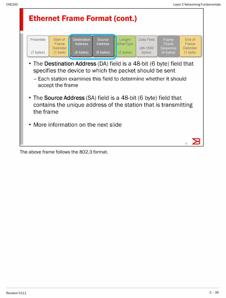
The above frame follows the 802.3 format.
Layer 2 Networking Fundamentals
2 – 39Revision 0111
CNE200
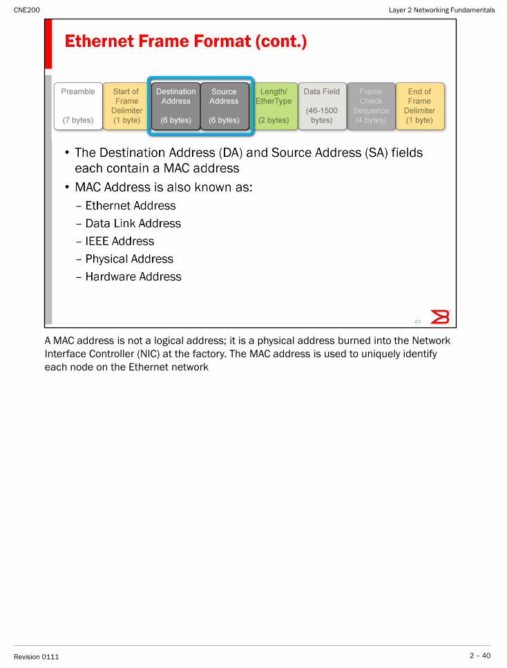
A MAC address is not a logical address; it is a physical address burned into the Network
Interface Controller (NIC) at the factory. The MAC address is used to uniquely identify
each node on the Ethernet network
Layer 2 Networking Fundamentals
2 – 40Revision 0111
CNE200
Layer 2 Networking Fundamentals
2 – 41Revision 0111
CNE200
Layer 2 Networking Fundamentals
2 – 42Revision 0111
CNE200
Layer 2 Networking Fundamentals
2 – 43Revision 0111
CNE200
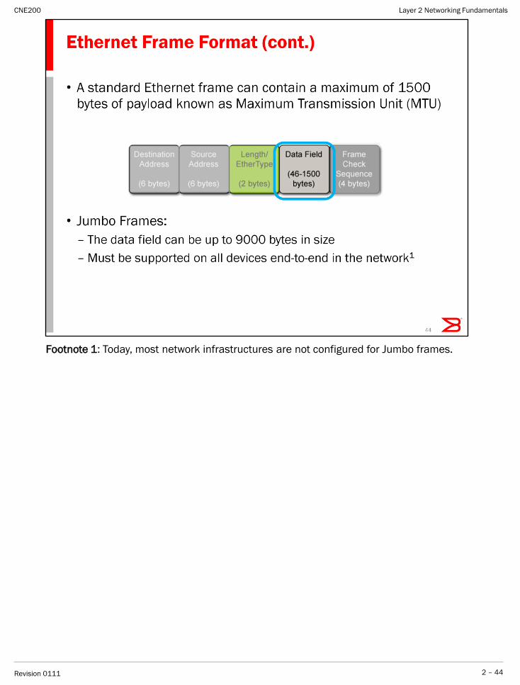
Footnote 1: Today, most network infrastructures are not configured for Jumbo frames.
Layer 2 Networking Fundamentals
2 – 44Revision 0111
CNE200
Layer 2 Networking Fundamentals
2 – 45Revision 0111
CNE200
Layer 2 Networking Fundamentals
2 – 46Revision 0111
CNE200