Embed Size (px)
Citation preview

Micr
Chapter 3 : Instruction Set & Assembly Languages Programming
POINTS TO REMEMBER
Instruction It is a binary pattern design inside a microprocessor to perform a specific function
Instruction basically consists of two parts The first part is called as op code and the second is called as operand
1 Byte instruction includes the op code and the operand in the 8 bit only
2 Byte instruction use 1St byte to specify the operation i e op code and second byte to specify the operand
3 byte instruction uses first byte to specify the operation i e op code, second and third bytes are used to specify the operand
The different methods to select the operands are called the addressing modes For 8085 they are , Immediate addressing Register addressing, Direct addressing Indirect addressing, Implied addressing
The instructions are generally classified into the functional

categories as follows
(i) Data transfer group(ii) Arithematic group(iii) Logical group(iv) Branching group(v) Stack and machine control group Stack is a reserved area of the memory This area is usually defined in RAM only It is used to store information (data) temporarily It is program by the user The stack related instructions are(i) PUSH R(ii) POPR(iii) SPHL(iv) XTHL

QUESTION-ANSWERS
Q 1. List categories of 8085 instructions that manipulate data. Ans. 8085 instruction, are:1. Data transfer instructions :(a) MOV(b) MVI(c) LDA(d) STA 2. Arithematic Instructions(a) ADD(b) AD)(c)SUB(ci) SBI

(f) DCR 3. Logical Instructions(a) ANA(b) ORI(c)CMP(d) RLC(e) RRC 4. Branch Instructions(a) JMP(b) CALL 5. Stack and machine control instructions(a) PUSH(b) POP.

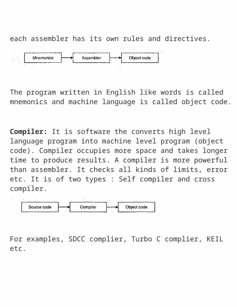
Q 2. Explain the function of assembler, compiler and interpreter. Ans. Assembler: It is a software which translates an assembly language program into a machine language program. Each microprocessor has its own assembler and each assembler has its own rules and directives.
The program written in English like words is called mnemonics and machine language is called object code. Compiler: It is software the converts high level language program into machine level program (object code). Compiler occupies more space and takes longer time to produce results. A compiler is more powerful than assembler. It checks all kinds of limits, error etc. It is of two types : Self compiler and cross compiler.
For examples, SDCC complier, Turbo C complier, KEIL etc.
Interpreter : Interpreter is also a software that converts high level language program into object codes. But this translation is done statement wise. It takes up one statement of high level language program at a time, translates it and executes it. It occupies less memory space. But it is slower as compared to compiler.
Q 3. Explain the difference between machine language and assembly language.Ans.
Q 4. The memory location 2500 H holds the data byte FFH Transfer this data byte to the accumulator using

instructions LDA, LDA X and MOV. Ans. LDA:
LXI 0, 2500 HLDAXD
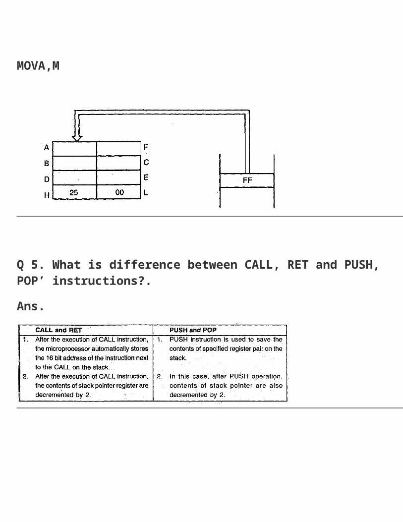
LXI H, 2500MOVA,M

Q 5. What is difference between CALL, RET and PUSH, POP’ instructions?.Ans.
Q 6. Write a program in assembly language program to sort the numbers in ascending order?
Ans. Assume that the memory block begins at D000H. And sort the 4 number.Program:MV) B, 09START: LXI H, D000H MV) C, 09HBACK: MOVA,MINXH CMPM JCSKIP JZSKlP MOVD,M MOV M, A DCX H MOVM,D INXHSKIP: DCRC JNZ BACK DCR B

JNZ START HLT
Q7. Write a program in assembly language program to find the square of numbers. Ans. The square of a numbers from memory locations D100H and store the resultsfrom location D200 H. Program: LXI H, D100H LXI D, D000H LXI B, D200HBACK: LDAXD MOV L, A MOVA,M

STAXB INX D INXB MOV A, C CPI 05H JNZ BACK HLT
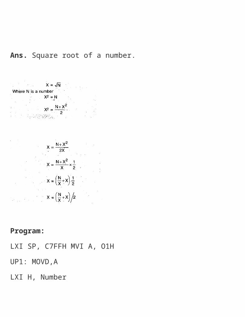
Q 8. Write a program in assembly language to find the square root of a number. Ans. Square root of a number.

Program:LXI SP, C7FFH MVI A, O1HUP1: MOVD,ALXI H, NumberCALL DIVMQVA,LADD DMVI H,00HMOV L, AMVI A, 02HCALL DIVMOVA, L
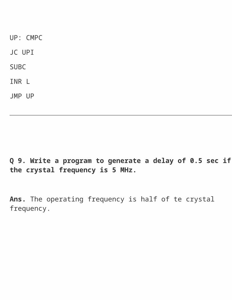
CMPDJNZUPIHLT Subroutine dlvMQV C, AMOV A, LMVI L,00UP: CMPCJC UPISUBCINR LJMP UP
Q 9. Write a program to generate a delay of 0.5 sec if the crystal frequency is 5 MHz.

Ans. The operating frequency is half of te crystal frequency.
Q 10. What happens when RET instruction is executed?
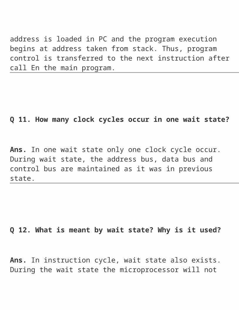
Ans When RET instruction is executed program control is transferred from the subroutine to the calling program. The return address is taken from stack, this address is loaded in PC and the program execution begins at address taken from stack. Thus, program control is transferred to the next instruction after call En the main program.
Q 11. How many clock cycles occur in one wait state? Ans. In one wait state only one clock cycle occur. During wait state, the address bus, data bus and control bus are maintained as it was in previous state.
Q 12. What is meant by wait state? Why is it used? Ans. In instruction cycle, wait state also exists. During the wait state the microprocessor will not initiate any new operation and just wait for current operation to be completed. During wait state the address, data and control bus are maintained in the previous T-state.

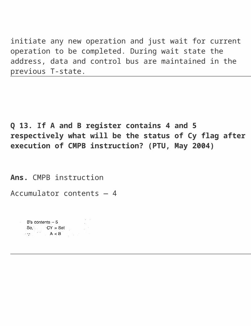
Q 13. If A and B register contains 4 and 5 respectively what will be the status of Cy flag after execution of CMPB instruction? (PTU, May 2004) Ans. CMPB instructionAccumulator contents — 4
Q 14. What will be the contents of PC after execution of RST 7 instruction? Ans. Contents of PC will be 0038 HTo calculates it:
1.Multiply 7 by 87 x 8 = 56
= 0038 H Will be address.
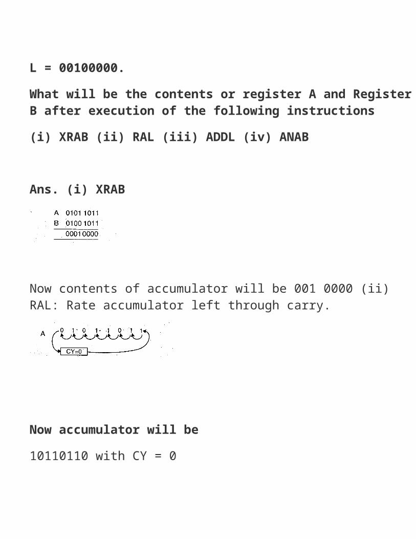
Q 15. The 8085 register contains the following dataA=O1O1 1011,B = 010 1011,H = 01000000,L = 00100000.What will be the contents or register A and Register B after execution of the following instructions(i) XRAB (ii) RAL (iii) ADDL (iv) ANAB Ans. (i) XRAB
Now contents of accumulator will be 001 0000 (ii) RAL: Rate accumulator left through carry.
Now accumulator will be10110110 with CY = 0(iii) ADDL
accumulator contents. (iv)ANABThis implies to and the accumulator contents and register B’s

contents
The result will be stored in accumulator
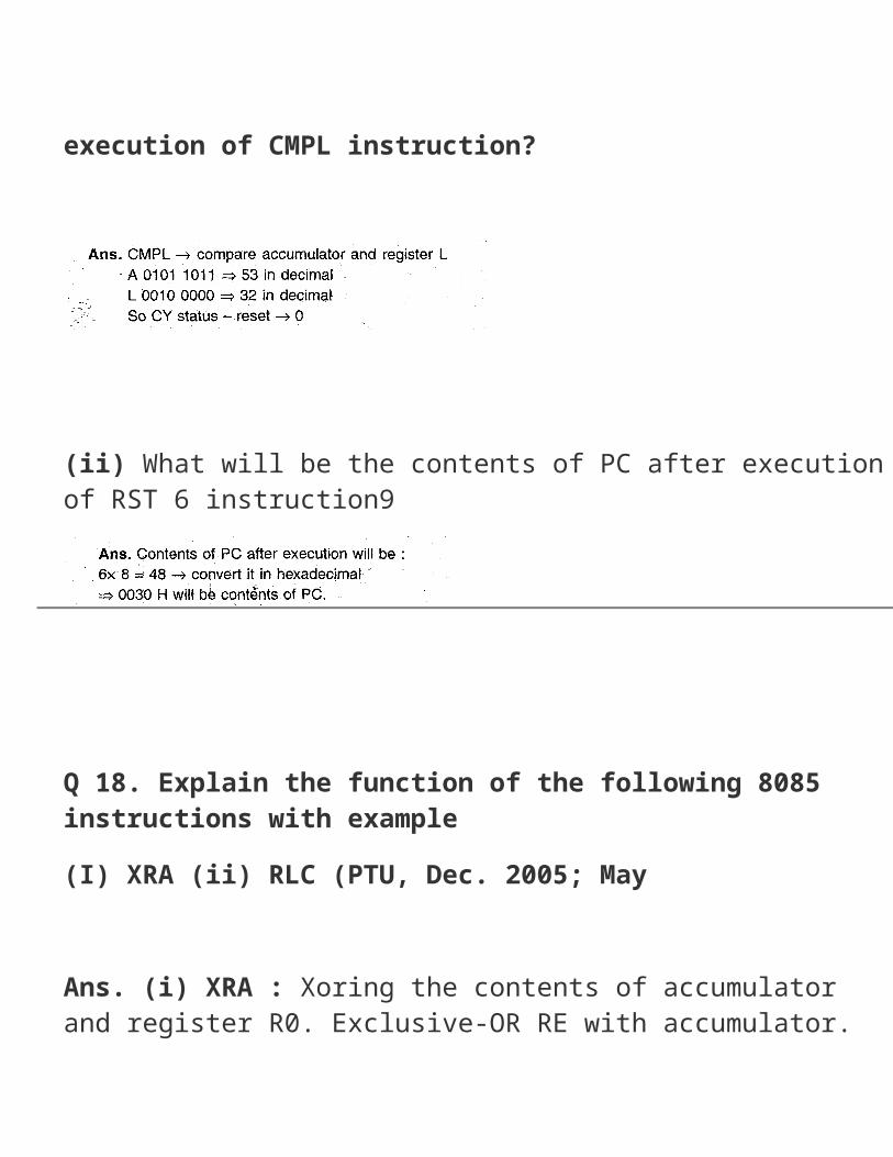
Q 16 What will be the status of CY flag after execution of CMPL instruction?
(ii) What will be the contents of PC after execution of RST 6 instruction9
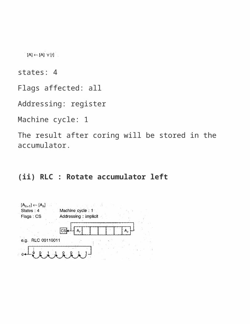
Q 18. Explain the function of the following 8085 instructions with example(I) XRA (ii) RLC (PTU, Dec. 2005; May Ans. (i) XRA : Xoring the contents of accumulator and register R0. Exclusive-OR RE with accumulator.
states: 4Flags affected: allAddressing: registerMachine cycle: 1The result after coring will be stored in the accumulator. (ii) RLC : Rotate accumulator left

Q 19. Discuss the function of the following signals to 8085.(i) RD (ii) ALE (PTU, Dec. 2005; May 2005) Ans. (i) : This is the control signal, RD . This signal is used both for reading memory and for reading an input device. It is necessary to generate two different read signals :one for memory and another for input. IO/M is used to do input-output or memory operations.(ii) ALE : This is an output signal. It is address latch signal. It goes high driving first sock cycle of a machine cycle and
enables the lower 8-bits of address to be latched either limo the memory or external latch. ALE = 0 = Data busALE = 1 = Address bus.This is a positive going pulse generated every time the 8085 begins an operation. ThisSignal is used primarily to latch the low order address bus from multiplexed bus.
Q 20. Find the errors in the following instructions.(I) POP CS ‘(ii) ROR BL, 04 (PTU, Dec. 2006) Ans. (I) POP CS : This instruction is used to copy a word that is pointed by stack pointer From the stack to the destination. The destination can not be CS because the code segment is used for the execution of main program. Hence, an error occurs in execution of instruction.(ii) ROR BL, 04 This instruction is used to rotate the contents of the register to the tight. The count is to be loaded in the CL
register. Hence, there is an error in the instruction execution. –
O 21. Write an assembly program that accepts a string of characters. Ans. Data segment SDB 1030, entire string: “$“ AR DB 1ODUP (0)Data ends Read Macro MOVAH, 01 INT 21Hendscode segments startMOV AX, dataMOV DS, AXDUPSLEA SI, ARcode ends.

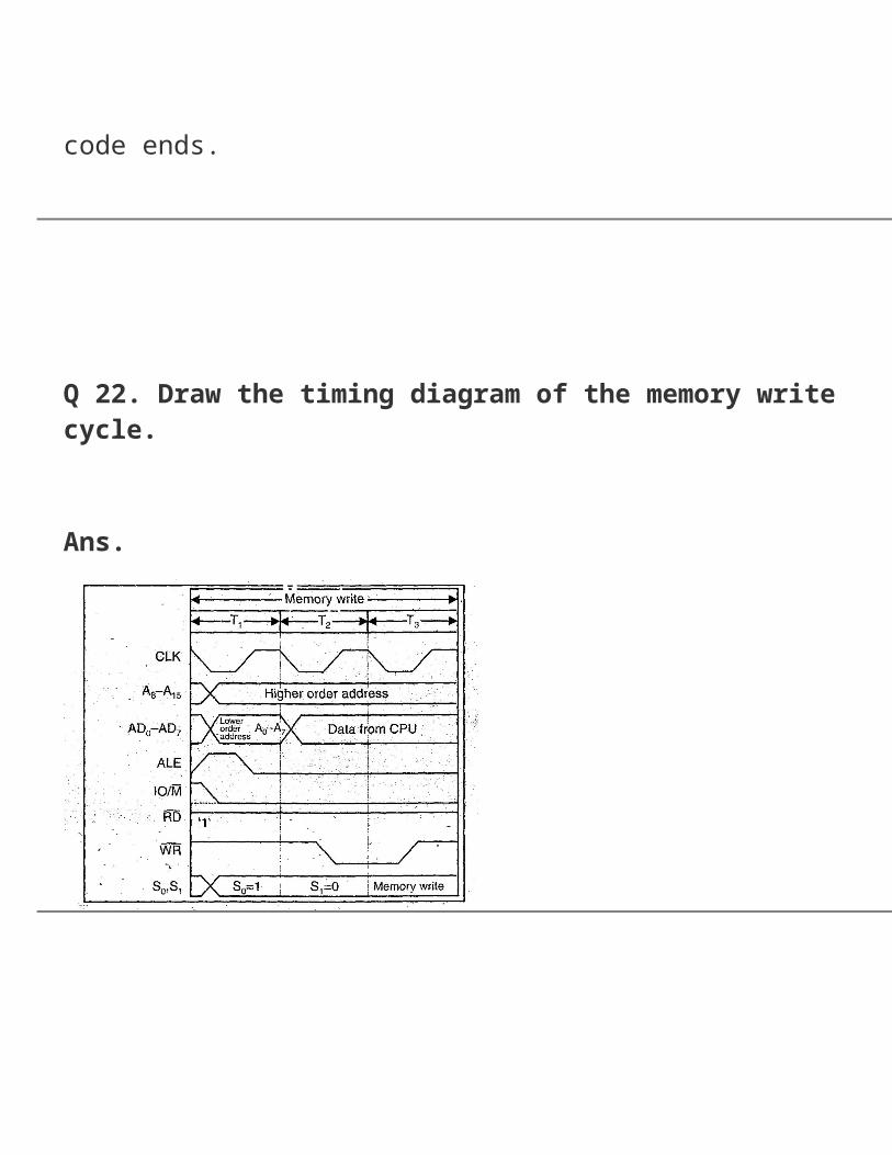
Q 22. Draw the timing diagram of the memory write cycle. Ans.
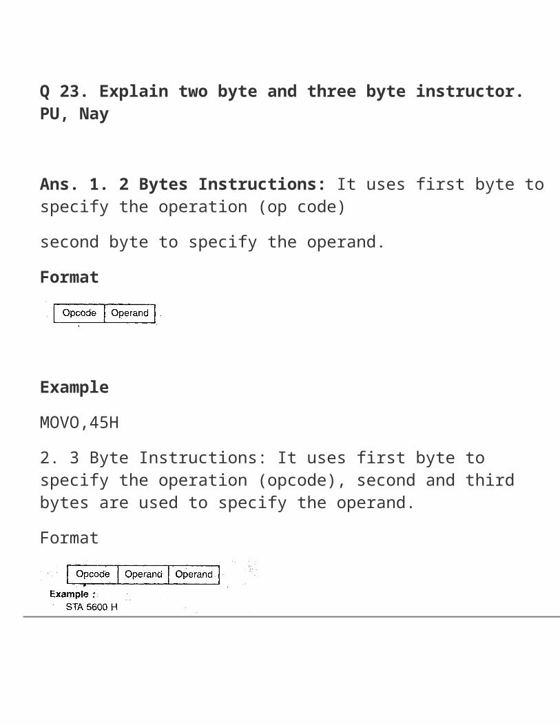
Q 23. Explain two byte and three byte instructor. PU, Nay Ans. 1. 2 Bytes Instructions: It uses first byte to specify the
operation (op code)second byte to specify the operand.Format
ExampleMOVO,45H2. 3 Byte Instructions: It uses first byte to specify the operation (opcode), second and third bytes are used to specify the operand.Format
Q 24. List the four categories of 8085 instructions that. manipulate data.(PTU, Dec.2007)
Ans. The four categories of instruction that mainpulate the data are1. Data transfer group2. Arithmetic group3. Logical group4. Machine group. –
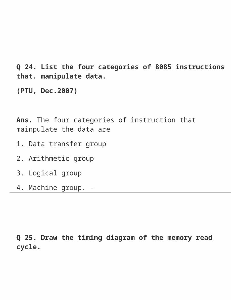
Q 25. Draw the timing diagram of the memory read cycle. Ans.
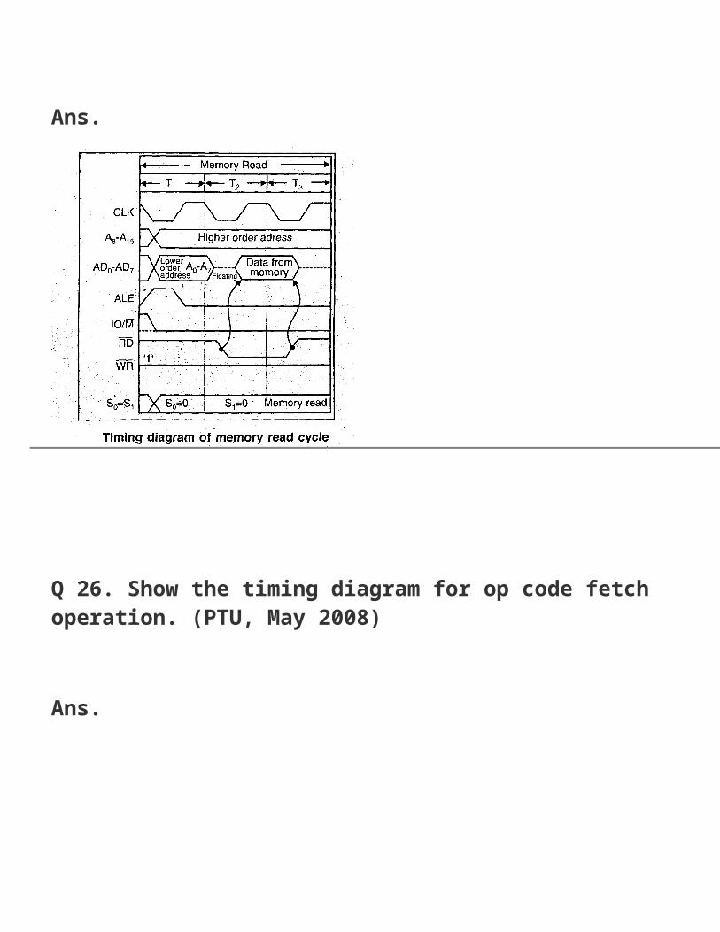
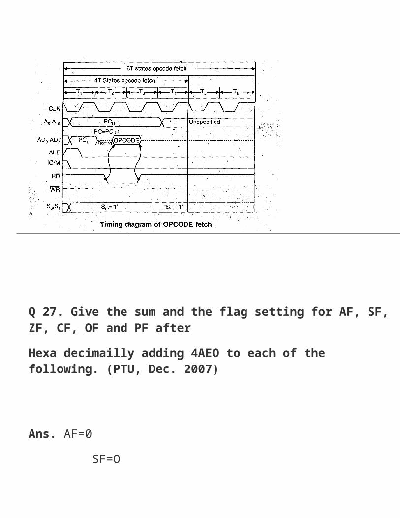
Q 26. Show the timing diagram for op code fetch operation. (PTU, May 2008) Ans.
Q 27. Give the sum and the flag setting for AF, SF, ZF, CF, OF and PF afterHexa decimailly adding 4AEO to each of the following. (PTU, Dec. 2007)
Ans. AF=0 SF=OZF=O
CF=1OF=0PFI
Q 28. Start:IN F2HCMAOR-AAJZ: start What wil be the result for this program? (PTU, May 2008) Ans. The program will go in infinite loop. Every time the accumulator is cleared the program will Jump to start.
Q 29. Give logical group instructions for 8085 p.R (PTU, May 2008)Ans.1.ANAR2.ANAM3. AM data4.ORAR5.ORAM6. ORA data7. CMA8. CMC9. STC10. RAR11. RAL12. CPI data .13.STC14. XRI data
Q 30. What do you meant by opcode and operands? (PTU, Dec. 2008) Ans. Opcode : Opcode is part of an instruction specifies the operations to be performed. Operands : Operands either provides the data or specifies data.The operand can be specified in a number of way.It includes:1. 8 bit/16 bit internal general purpose register.2. A memory location.3. 8 bit port address/16 bit memory address.4. Implicit operand : The operand is not specified, instead it is assumed in register.
Q 31. What are the op code, data type and operand in the instruction MOV AH, 7? (PTU, May 2009)

Ans. In the instruction MQV AH, 71. MOV is the op code.2. AH is the operand is data.
Q 32. Define instruction cycle and machine cycle. (PTU, May 2009) Ans. Instruction Cycle The steps required by CPU to fetch and execute an instruction is called an instruction cycle. It consists of a fetch cycle and an execute cycle. The time required to execute an instruction isInstruction Cycle = Fetch Cycle + Execution Cycle. IC = FC ÷ EC Machine Cycle: It is the time required by the microprocessor to complete the operation of accessing memory or I/O device is called as a machine cycle. It perform specified operation
like op code fetch, memory read, memory write, I/O read, I/O write t performed in a machine cycle.
Q 33. List any four unconditional branch instructions. Ans. 1.MOVD,B2. ADD B3. PCHL4. STA C200H
Q 34. What is the difference between MOV AX, 1000H AND MOV AX, [1000H]? (PTU, Dec. 2009) Ans. MOV AX, 1000H = Immediate Addressing ModeMOV AX, [1000H] = Indirect Addressing Mode.
Q 35. Register AX, BX and CX contain the respective values 2000H, 1000H and 3000H. What is the result of CMPXCHG BX, CX? (PTU, Dec. 2009) Ans. AX=2000HBX = 3000HCX = 1000H
Q 36. What is three byte instruction? Give example. (PTU, Dec. 2009) Ans. In case of three byte instruction, first byte to specify the operation (First bytestored is op code), second byte stored is lower 8 bits of 16 bit operand/address and third byte stored is higher order 8 bits of 16 bits operand or address.eg:
1. LXI H, 1243 HOp code = 21HSecond byte = 34 HThird byte = 12H2. STA266OHOp code = 32 HSecond byte = 60 HThird byte = 26 H
Q 37. Give the significance of SIM and RIM instruction available in 8085.(PTU, Dec. 2009) Ans. SIM (Set Interrupt Mask): In this, we can change the priorities of RST 7.5, RST 6.5 and RST 5.5 by masking or unmasking them as desired. This instruction is also used for serial data output which do not affects the interrupts.
For example,MVI A, Control formatSIM H is stored in the next memory location. For e.g., SHLD 2040h will store the content of register L in the memory location 2040h. The content of the register H is stored in the memory location 2041h. (b) STAXd: This is 1-byte instruction that will store the content of the accumulator in the memory location whose address is in D-E pair. This instruction is true only for register pairs B-C and D-E.(c) DAA (Decimal Adjust accumulator) : The instruction DAA is used in the program after ADD, ADI, Act, ADC etc. instructions. After the execution of ADD, ADC, etc. instruction the result is in hexadecimal and it is placed in the accumulator. The DAA instruction operates on this result and gives the final result in decimal system. It uses carry and auxiliary carry for decimal adjustment. 6 is added to 4 LSBs of the content of the a6cumulator if their value lies in between A and F or the AC flag is set to 1. Similarly, 6 is also added to 4 MSBs of the content of the accumulator if their value lies in between A and F or the CS flag is et to 1. All status flags are affected. When DAA is used, data should be in decimal numbers.

Q 39. Draw the timing diagram of MOVB, A instruction. Ans.
Q 40 Write a program to divide 16 bit no by 8 bit no
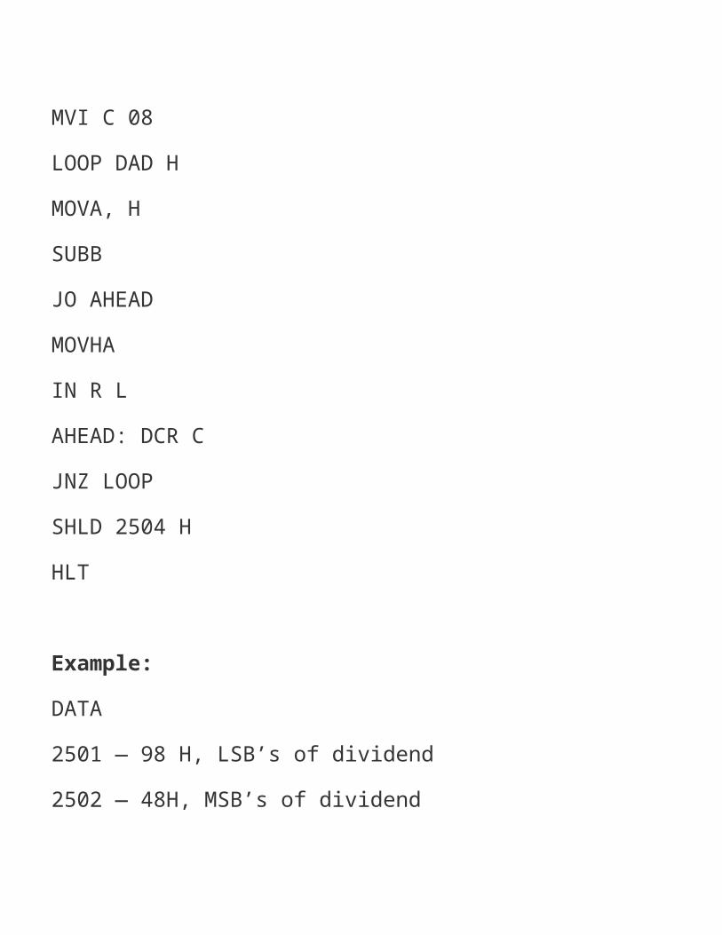
AnsLHL D 2501 HLDA25O3HMOVB,AMVI C 08LOOP DAD HMOVA, HSUBBJO AHEADMOVHAIN R LAHEAD: DCR CJNZ LOOPSHLD 2504 HHLT Example:
DATA2501 — 98 H, LSB’s of dividend2502 — 48H, MSB’s of dividend2503 — 1 A H Divisor Result2504 — F2, Quotient2505 —> 07, Remainder
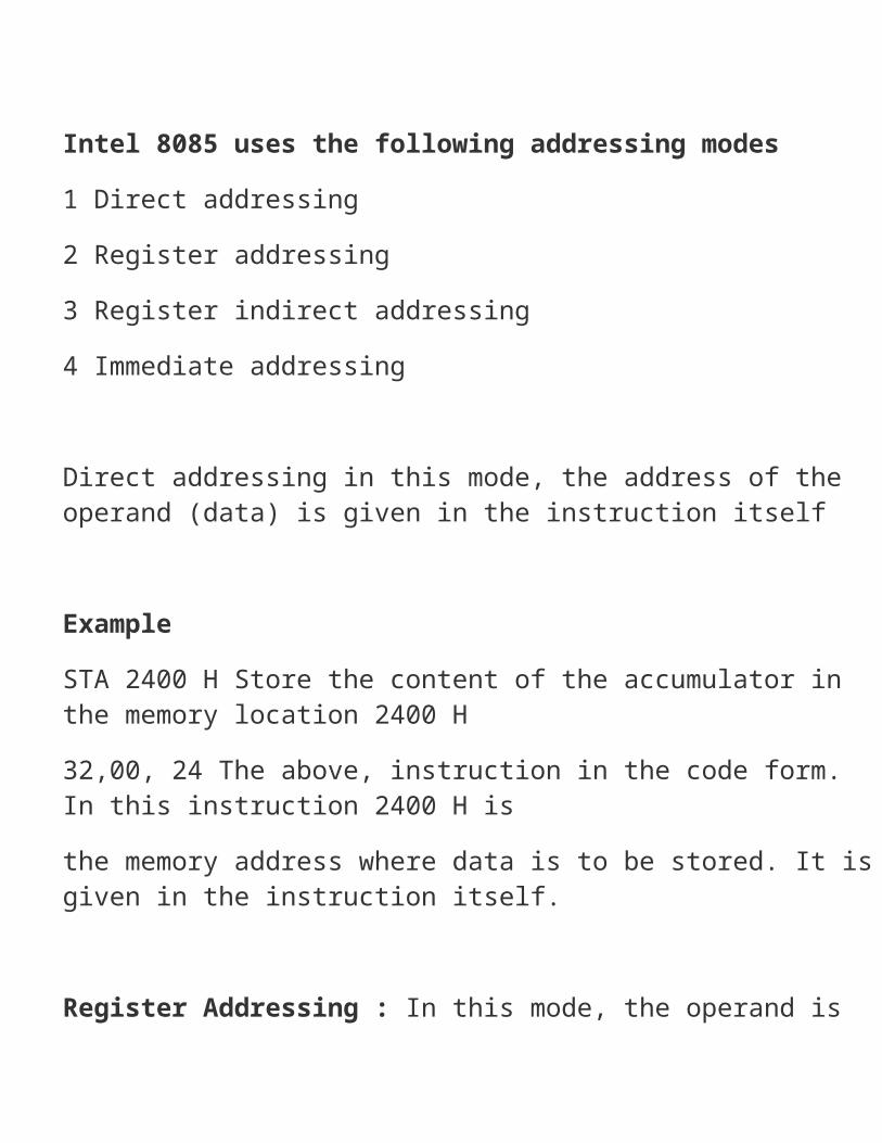
Q 41 Discuss various addressing mode of 8085ORDiscuss various addressing modes of 8085 Explain with examples Ans A microprocessor must address the memory to obtain or store data There are several ways in which to generate an address when an instruction is being executed These are called the addressing modes of the microprocessor Such addressing modes ensure wide programming flexibility
Intel 8085 uses the following addressing modes1 Direct addressing2 Register addressing3 Register indirect addressing4 Immediate addressing Direct addressing in this mode, the address of the operand (data) is given in the instruction itself ExampleSTA 2400 H Store the content of the accumulator in the memory location 2400 H32,00, 24 The above, instruction in the code form. In this instruction 2400 H isthe memory address where data is to be stored. It is given in the instruction itself. Register Addressing : In this mode, the operand is in one of the general purpose registers. The op code specifies the address of the register (s) in addition to the operation to be performed.
Eg:MOV A, B Move the content of register B to register A.78 The instruction in the code form:The op code for more A, B is 78 H. Besides the operation to be performed, the op code also specifies source and destination registers. The op code 78, H can be written in binary form as 01111000.Register Indirect Addressing: In this mode, the address of the operand is specified by a register pair. eg.LXIH, 2500 H Load H-L pair with 2500 H Move the content of the memory location,MOV A, M whose address is in H-L pair (2500 H) to the accumulatorHLT Halt

Immediate Addressing: In this mode, the operand is specified with in the instruction itself. eg.MVIA, 05 MOV 05 in register A3E, 05 the instruction in the code form.
Q 42. Explain the following instructions.(a)MOVA, M(b)DAA(c) JMP 2000H Ans. (a) MOV A, MThis instruction has accumulator and memory pointer (M). This is a 1 -byte instruction.[rJ <— [[H — L]] moving content’ of memory to register
States:7Flag affected: NoneAddressing: register indirectMachine cycles: 2The content of the memory location, whose address is in H-L pair is moved to register r. Example:LXI H, 2000 H — Load H-L pair by 2000 HMOV A, M — Move content of memory location to register BH LTRags: allMachine cycles: 1 The instruction DAA is used in the program after ADD, AD1, AC ADC etc. instructions. After the execution of ADD, ADC etc. in hexadecimal and it is placed in accumulator. The DAA instruction operates on the his result and given the final result in decimal system. It uses carry and auxiliary carry for decimal adjustment. 6 is added to 4 LSB’s of the content of the accumulator if their value was between A and F or if AC
flag is set to 1. Similarly, 6 is added to 4 MSB’s content JMP 2000 H.This is an instruction which change the normal sequence of the program. This is an unconditional jump i.e. jump to the instruction specified by the address. The unconditional branch instruction transfer the program to the specified label unconditionally. [PC] f— LabelStates: 10Flags affected: NONEAddressing mode : ImmediateMachine cycle . 3Here byte 2nd and byte 3rd or the instruction give the address of the label where the program jumps.The address of the label is the address of memory location for next instruction to be executed.Here op codes generated will beJMPC3H
Lower byte 00 HHigher byte 20 H
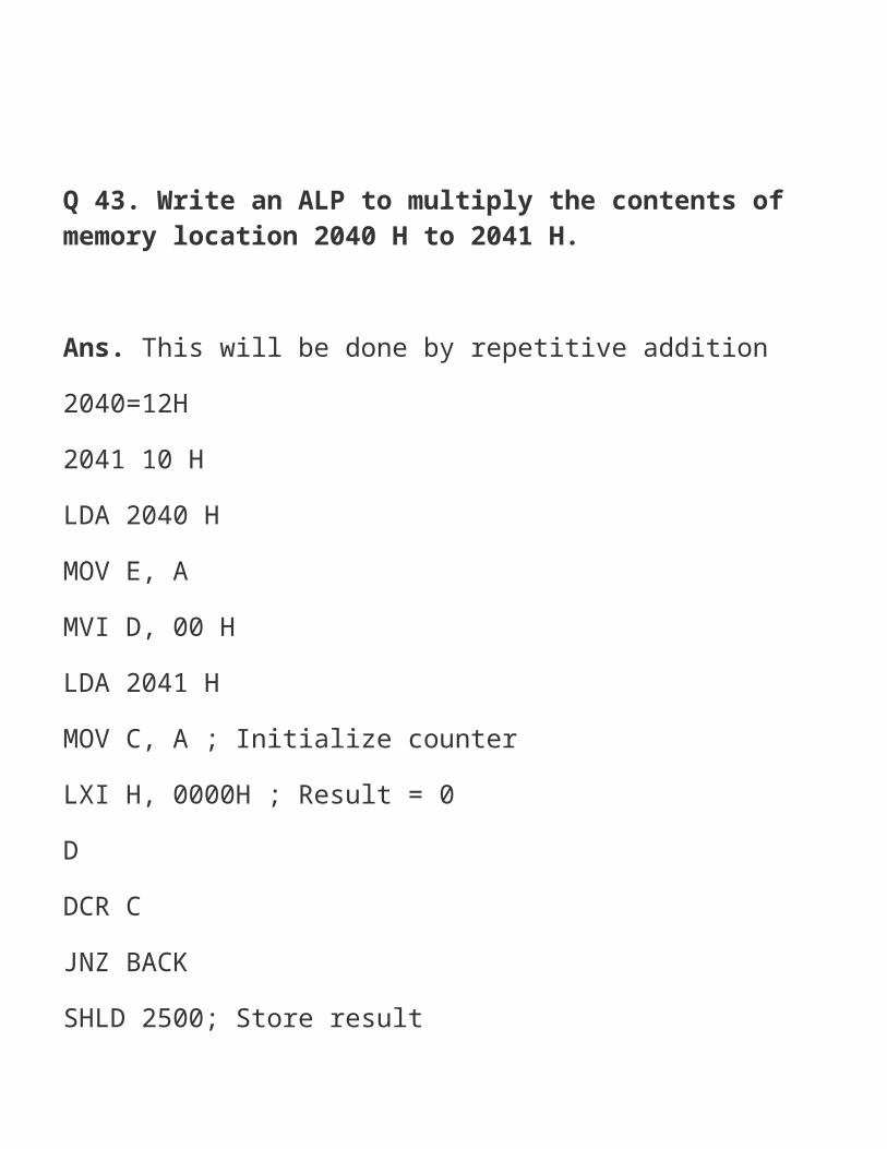
Q 43. Write an ALP to multiply the contents of memory location 2040 H to 2041 H. Ans. This will be done by repetitive addition2040=12H2041 10 HLDA 2040 HMOV E, AMVI D, 00 HLDA 2041 HMOV C, A ; Initialize counterLXI H, 0000H ; Result = 0DDCR C

JNZ BACKSHLD 2500; Store resultHLT.(b) DAA [Decimal adjust accumulator] States: 4
Q 44. Draw timing diagram for MOV A, M instruction. Ans. This will have 7-T states Op code 7E hLXIH 2500 H M is the memory pointer 2500 - 20HMOV A, M . 2501 — 32H

Q 45. Explain the function of the following 8085 instructions with examples.(a) LHL.D(b)XCHG(c) STA(d) JNC(e) MVI

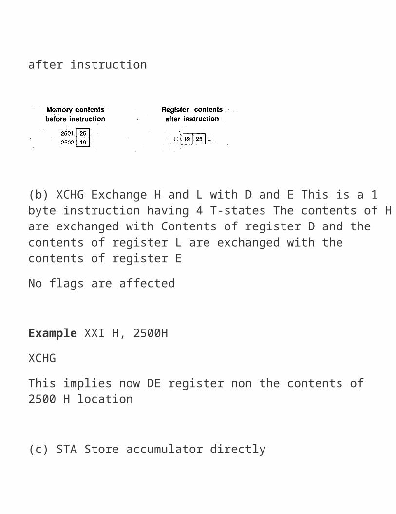
Ans. (a) LHLD : Load HL pair directly Op code Operated Bytes M-cycles. T-states Hex-codeLHLD 16-bit 3 . 5 16 2AAddressThis instruction copies the contents of memory location pointed out by the 16-bit address in register L and copies the contents of the next memory location in register H. The contents of source memory location are not altered. VFlags are not affected by this instructions. ExampleLHLD 2500H Memory contents Register contents before instruction after instruction

(b) XCHG Exchange H and L with D and E This is a 1 byte instruction having 4 T-states The contents of H are exchanged with Contents of register D and the contents of register L are exchanged with the contents of register ENo flags are affected Example XXI H, 2500HXCHGThis implies now DE register non the contents of 2500 H location (c) STA Store accumulator directlyThis is a 3-byte instructions In this the contents of the accumulator are copied to a memory location specified by the operand This is a 3 byte instruction, the second byte specifies the low order address. No flags are affected;
Accumulator — [Memory location] STA 2500HAccumulator — [2500 H](CJ) JNC — Jump if no carries.This is a branch instruction[PCI — address (label) if CY = 0 States 7/10 flags-NONEAddressing immediate
Q 46 Write an 8085 based assembly language program to arrange a series ofnumbers in descending orderORWrite an 8085 based assembly language program to find the square root of anumber Ans LXI H, 2500MOVC,M
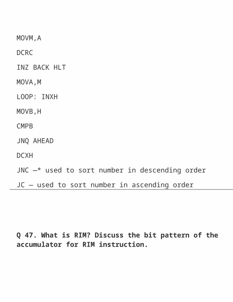
BACK LXI H, 2500MOVD,MINXH MOVM,AMOV A, BJMP GOAHEAD: DCX H MOVM,BGO: INXH DCR DJNZ LOOPMOVM,ADCRCINZ BACK HLTMOVA,MLOOP: INXHMOVB,HCMPBJNQ AHEAD
DCXHJNC —* used to sort number in descending orderJC — used to sort number in ascending order
Q 47. What is RIM? Discuss the bit pattern of the accumulator for RIM instruction. Ans. RIM: Read interrupt maskThis is a 1-byte instruction.This instruction loads the accumulator with eight bits indicating the current status of the interrupt mask. The interrupt enable, pending interrupts and serial input data. Note:This instruction RIM checks for a pending interrupt. Here, the bit patterri is explained

D6, D5, D4 : To indicate the pending interrupts pending interrupts may be defined as more which are not till executed or accepted by the microprocessor. When one interrupt request is being served other interrupt requests may occur and remain pending. D6 = 1 RST 7.5 pending 0 — being served. SID: Serial input data bit.
Q 48. Write an assembly language program to calculate the 2’s complement of 16 bit no..
Ans.ProgramLDA C200H.CMAADI O1HSTA C300HHLTThe 2’s complement of the number stored atComplemented number at memory location C300HMemory location C200H and store
Q 49 Write an assembly language program until the user types 5 that reads numbers from the users Ans. Subroutine:Subroutine : LXI H, 2500HMVI C,00H
MOV A,MCMAADI 0,1MOV M,A.JNC DNINR CMain programINX HMOV A,MCMAADD BMOV M, ARETPUSH PSWPUSH BPUSH HCALL SubroutinePOP H

POPPOPH LTDN:BDW
Q 50 Write an assembly language program to generate Fibonacci sequence Ans. The Fibonacci sequence is: 1 1 2 3 5 8 13 21 Nth termNth term = (N — 2)th term + (N — 1)th term

Program:MVI D, countMVI B, 000MVI C,01HMOV A,BACK: ADD CMOV B, CMOV C,ADCR DJNZ •BACKHLT
Q51.The instruction code 0100 1111 (4FH) is stored in memory location 2005 H. Illustrate the data flow and list of sequence of events when the instruction code is fetched by MPU. (PTU, Dec. 2007)
Ans. To fetch the instruction located in memory 2005 H, the following steps are performed:1. The program counter places the 16 bit address 2005 H of the memory location on the address bus.2. The control unit sends the MEMR signal to enable the output buffer of the memory chip.3. The instruction (4FH) stored in the memory location is placed on the data bus and transferred to the instruction decoder of the microprocessor.4. The instruction is decoded and executed according to the binary pattern of the instruction.
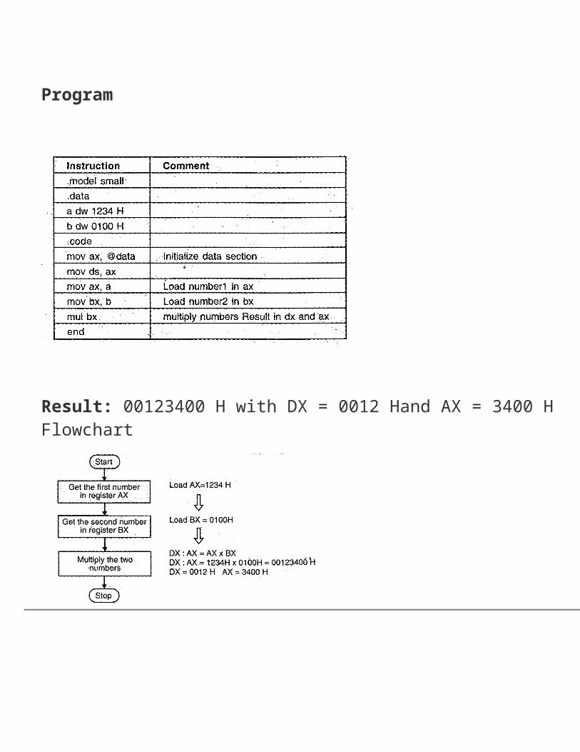
Q 52. Write an assembly language program for 16 bit multiplication.(PTU, May 2008) .Ans. Program statement:• Assuming that two words are available in registers AX and BX, write a program in the assembly language of 8086 to multiply two 16 bit unsigned numbers.

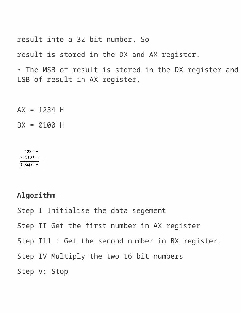
Explanation• Consider that a word of data is present in the AX register and 2nd word of data is present in the BX. register.• We have to multiply the word in AX with the word in BX. Using MUL instruction, multiply the contents of the 2 registers. -• The multiplication of the two 16 bit numbers may result into a 32 bit number. Soresult is stored in the DX and AX register.• The MSB of result is stored in the DX register and LSB of result in AX register. AX = 1234 HBX = 0100 H
Algorithm
Step I Initialise the data segementStep II Get the first number in AX registerStep Ill : Get the second number in BX register.Step IV Multiply the two 16 bit numbersStep V: StopProgram
Result: 00123400 H with DX = 0012 Hand AX = 3400 H Flowchart

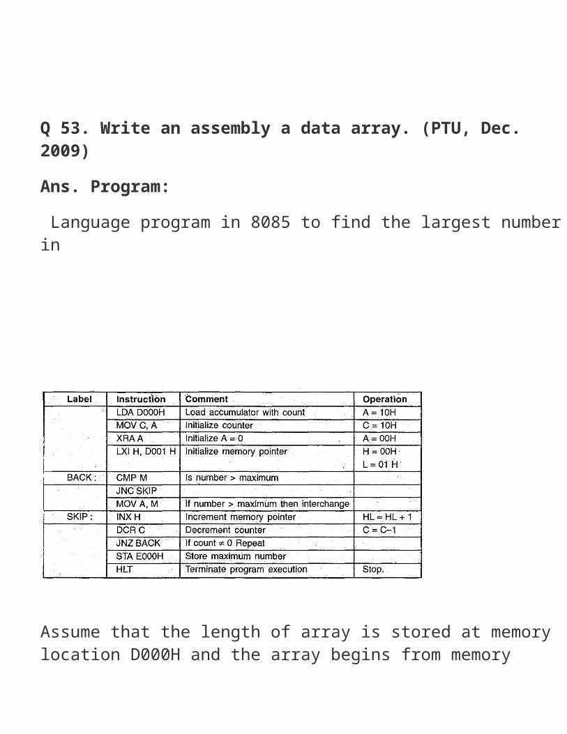
Q 53. Write an assembly a data array. (PTU, Dec. 2009)Ans. Program: Language program in 8085 to find the largest number in

Assume that the length of array is stored at memory location D000H and the array begins from memory location DOOl H. Store the maximum number at memory location E000H.
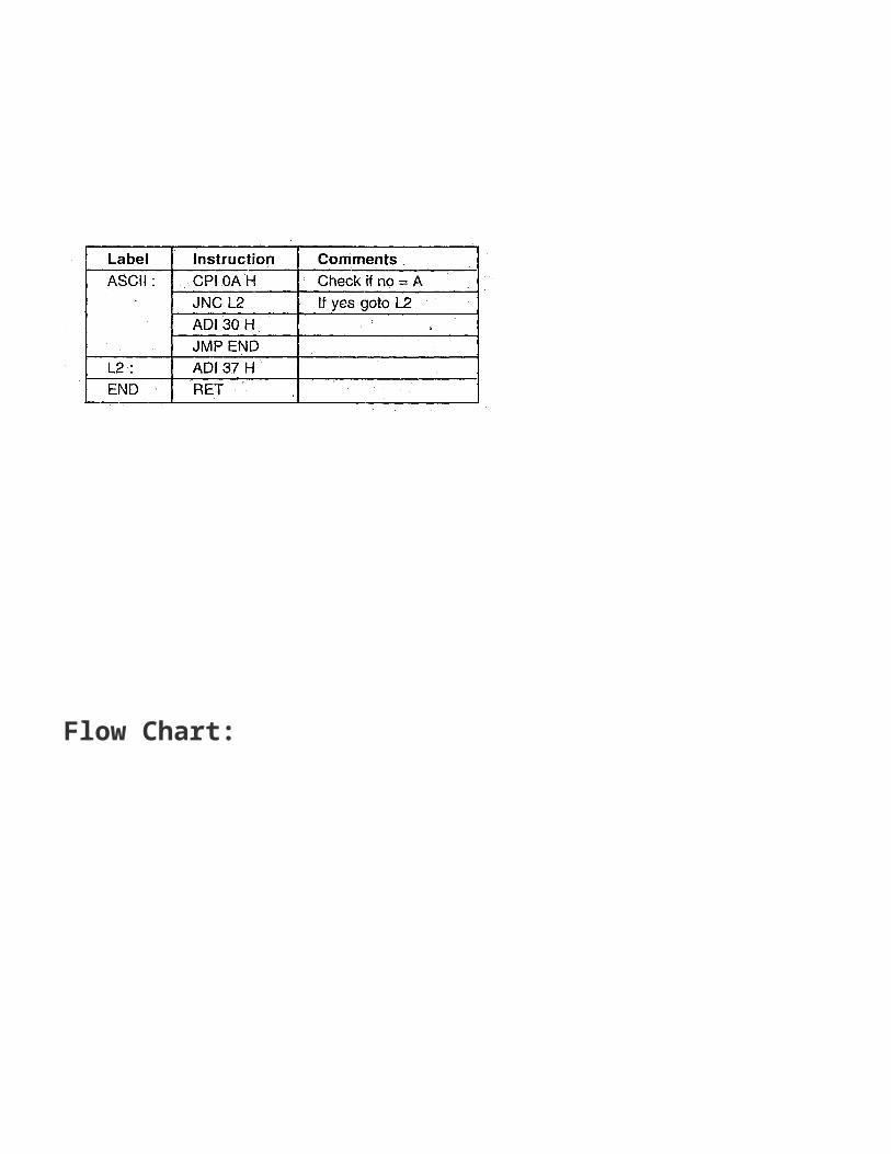
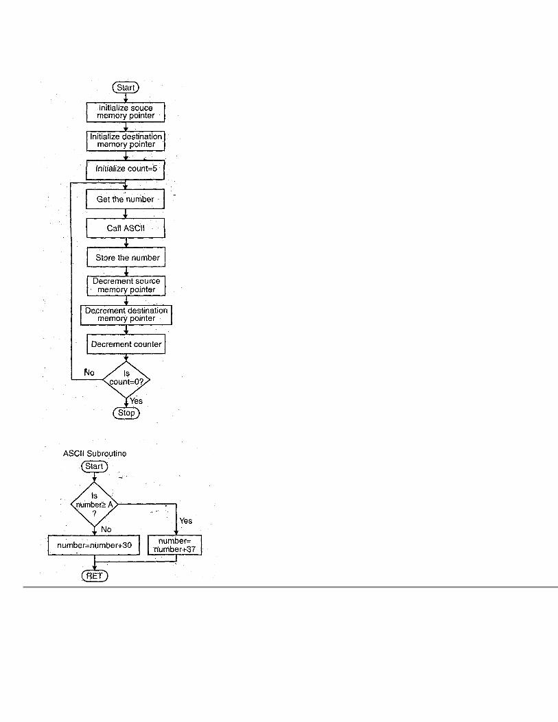
Q 54. Write an 8085 assembly language program to convert 8 bit binary to ASCII code. (PTU, May 2009) Ans. Program
ASCII Subroutine:

Flow Chart:
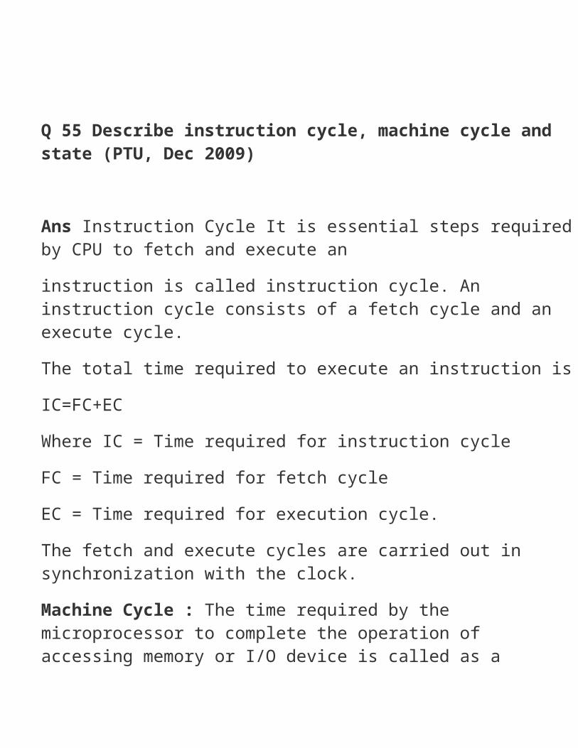
Q 55 Describe instruction cycle, machine cycle and state (PTU, Dec 2009) Ans Instruction Cycle It is essential steps required by CPU to fetch and execute aninstruction is called instruction cycle. An instruction cycle consists of a fetch cycle and an execute cycle.The total time required to execute an instruction isIC=FC+ECWhere IC = Time required for instruction cycleFC = Time required for fetch cycleEC = Time required for execution cycle.

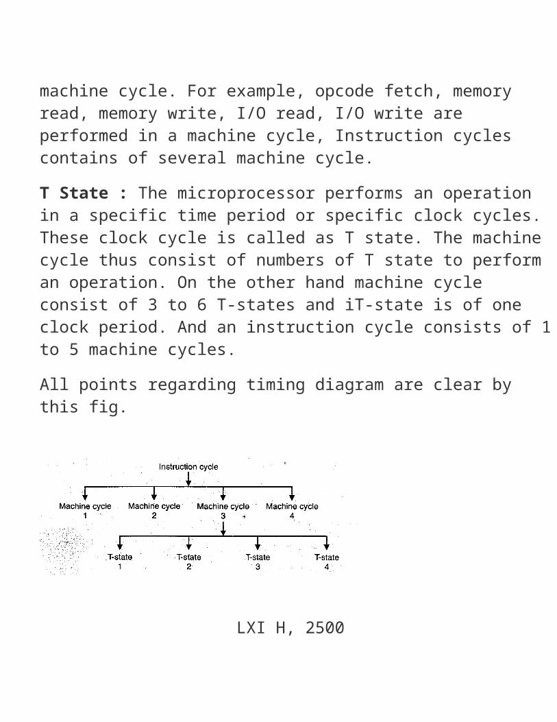
The fetch and execute cycles are carried out in synchronization with the clock.Machine Cycle : The time required by the microprocessor to complete the operation of accessing memory or I/O device is called as a machine cycle. For example, opcode fetch, memory read, memory write, I/O read, I/O write are performed in a machine cycle, Instruction cycles contains of several machine cycle.T State : The microprocessor performs an operation in a specific time period or specific clock cycles. These clock cycle is called as T state. The machine cycle thus consist of numbers of T state to perform an operation. On the other hand machine cycle consist of 3 to 6 T-states and iT-state is of one clock period. And an instruction cycle consists of 1 to 5 machine cycles.All points regarding timing diagram are clear by this fig.
LXI H, 2500
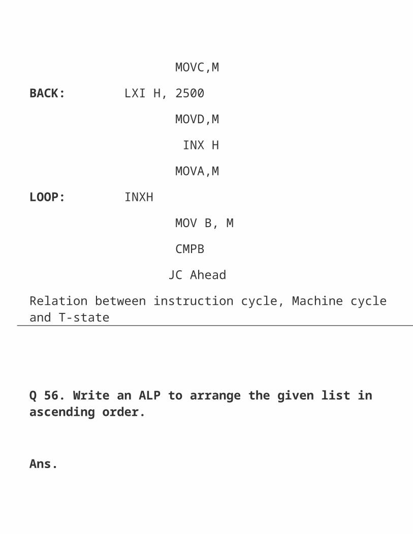
MOVC,MBACK: LXI H, 2500 MOVD,M INX H MOVA,MLOOP: INXH MOV B, M CMPB JC AheadRelation between instruction cycle, Machine cycle and T-state
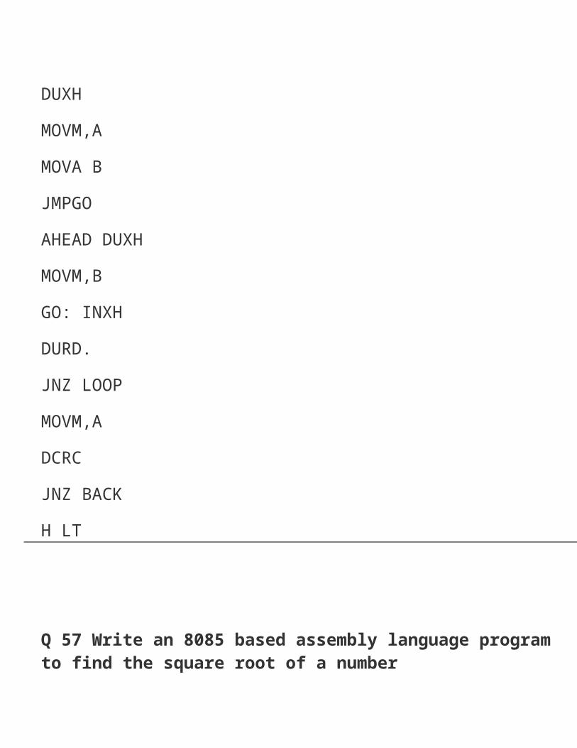
Q 56. Write an ALP to arrange the given list in ascending order. Ans.DUXHMOVM,A
MOVA BJMPGOAHEAD DUXHMOVM,BGO: INXHDURD.JNZ LOOPMOVM,ADCRCJNZ BACKH LT
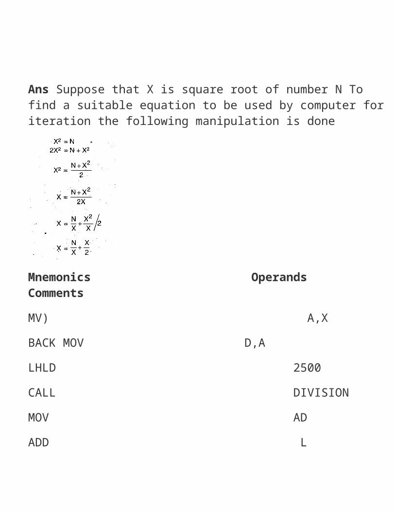
Q 57 Write an 8085 based assembly language program to find the square root of a number Ans Suppose that X is square root of number N To find a suitable equation to be used by computer for iteration the following manipulation is done
Mnemonics Operands CommentsMV) A,XBACK MOV D,ALHLD 2500CALL DIVISIONMOV ADADD LMOV LAMV) H00MV) A02CALL DIVISIONMOV A,L

CMP DJZ BELOWJMP BACK
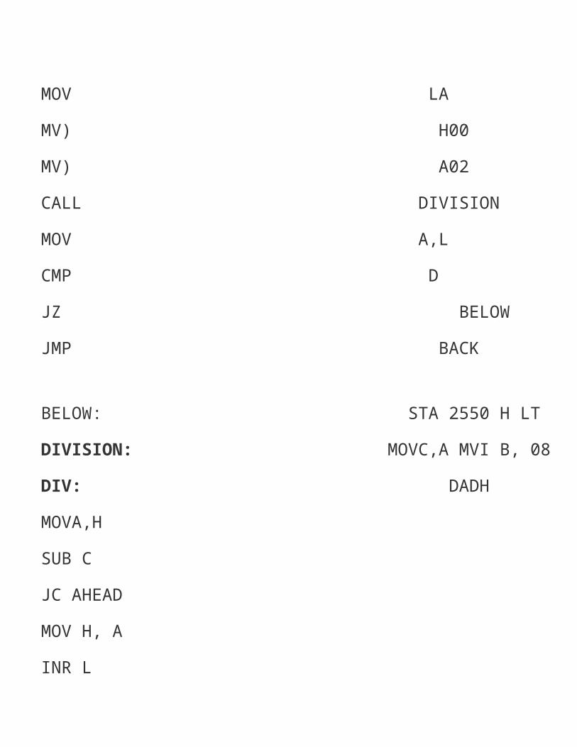
BELOW: STA 2550 H LTDIVISION: MOVC,A MVI B, 08DIV: DADHMOVA,HSUB CJC AHEADMOV H, AINR LAHEAD: DCRBJNZ DIVSHLD 2503RET
Example:
DATA2500—,19H2501 —, 00
RESULT:2550 — 05H
Q 58. Write an assembly language programme to get the 2’s complement of a 16-bit number. Ans.LXI H, 2501 H ; LSBs in accumulatorMVI B, 00 ; Use register to store carryMOV A. M ; LSBs in accumulatorCMA is complementADI 01 2’s complementSTA 2503 H ; store resultJNCGO
INR B Store carryGO : INX H Address of 8 MSBs of numberMOV A,MCMA ; 1’s complement of MSB’sADD B Add carry
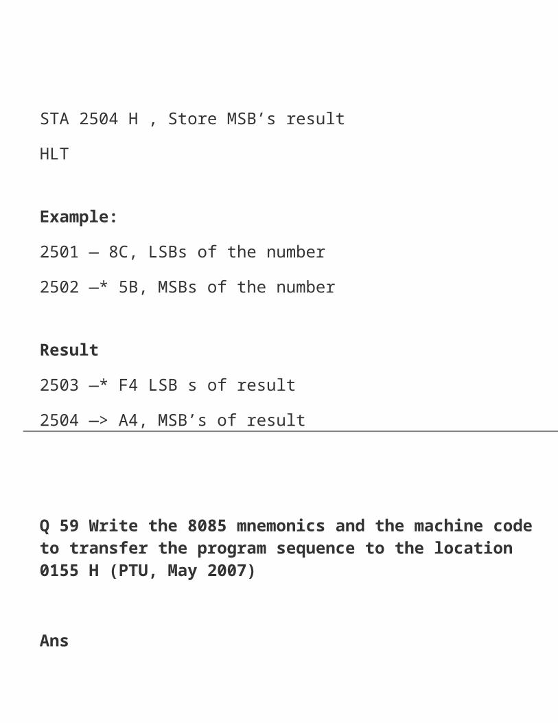
STA 2504 H , Store MSB’s resultHLT
Example:2501 — 8C, LSBs of the number2502 —* 5B, MSBs of the number
Result2503 —* F4 LSB s of result2504 —> A4, MSB’s of result
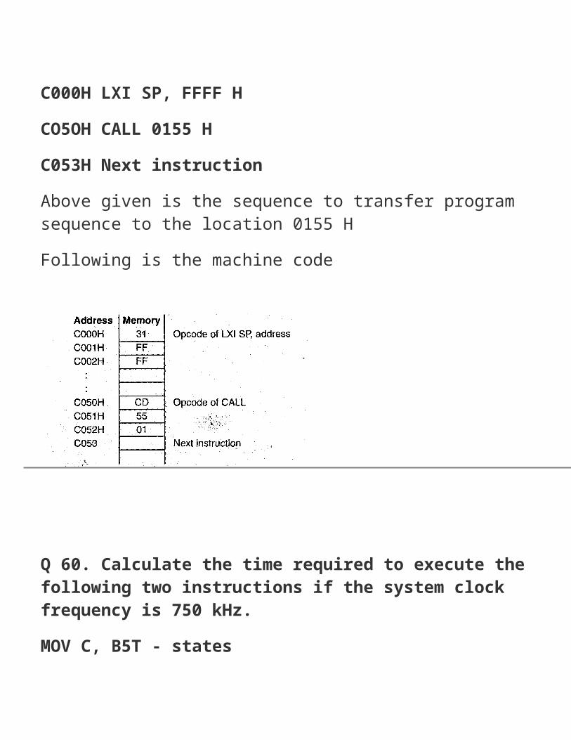
Q 59 Write the 8085 mnemonics and the machine code to transfer the program sequence to the location 0155 H (PTU, May 2007) AnsC000H LXI SP, FFFF HCO5OH CALL 0155 HC053H Next instructionAbove given is the sequence to transfer program sequence to the location 0155 HFollowing is the machine code
Q 60. Calculate the time required to execute the following two instructions if the system clock frequency is 750 kHz.MOV C, B5T - statesJMP 2050 HiD f state. (PTU, May 2007) Ans. T-states required for executionT = 15Operating frequency is 750 kHz.Time required to execute the instructions = 15 x 0.001 33 ms = 19.95 is
Q 61. Write instructions to clear the CV flag, to load number FFH in register B, and increment (B). If the CY flag is set, display 01 at an output port; otherwise display the contents of register B. (PTU, May 2007) Ans. Program:
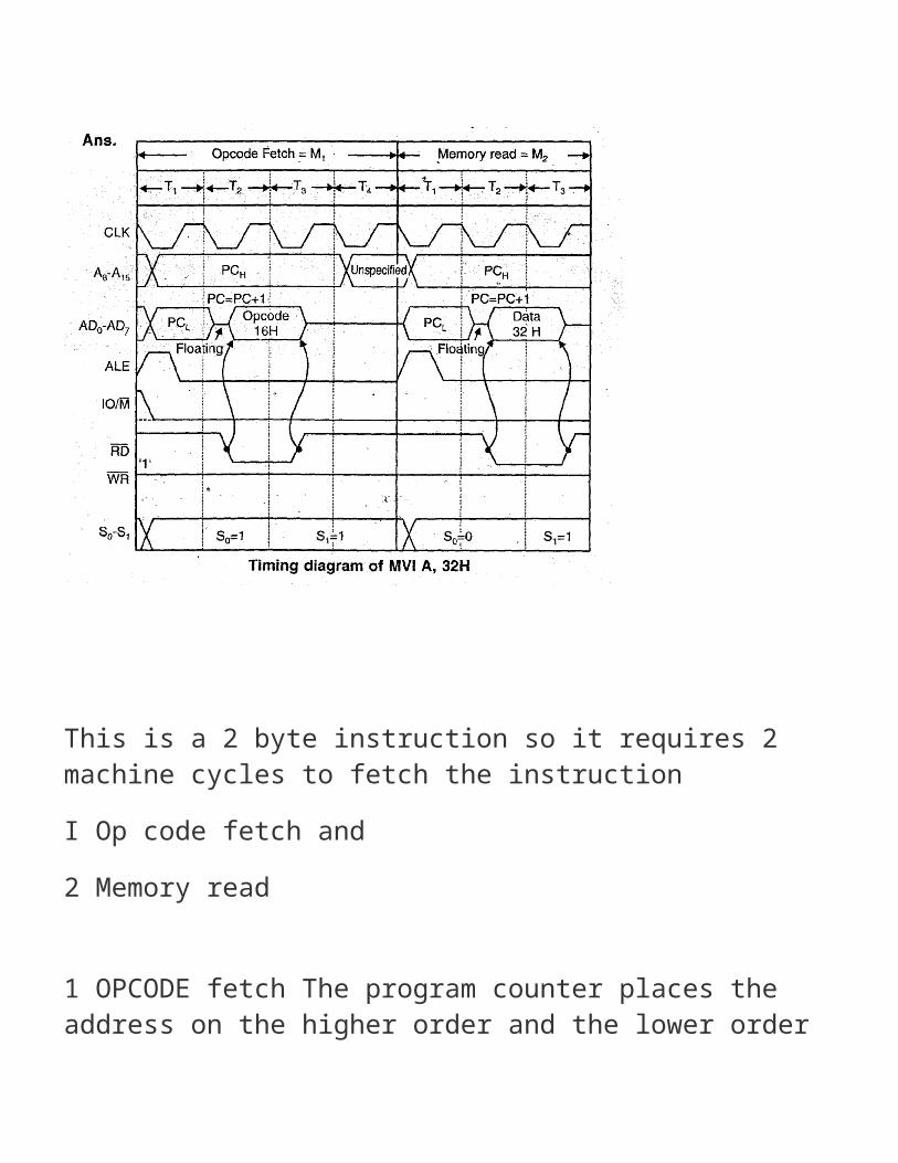
0 62. Draw the 8085 timing of execution of the 2 byte instruction MVI A, 32H (load the accumulator with the data 32 H) store in location as followsMemory location Machine Code Mnemonics2000 3E MVIA,32H2000 32 Ans.
This is a 2 byte instruction so it requires 2 machine cycles to fetch the instructionI Op code fetch and2 Memory read
1 OPCODE fetch The program counter places the address on the higher order and the lower order address bus The op code at this memory location is read into the
microprocessor The PC is then incremented by 1 to point to the next byte This machine cycles requires 4 T states
This is a 2 byte instruction so it requires 2 machine cycles to fetch the instructionI Op code fetch and2 Memory read
1 OPCODE fetch The program counter places the address on the higher order and the lower order address bus The op code at this memory location is read into themicroprocessor The PC is then incremented by 1 to point to the next byte This machine cycles requires 4 T states
2 Memory Read The data is read from the addressed memory location into the specific register The PC is again incremented by one to point to next instruction after MVIThe same timing diagram is applicable to following instructions also ACI data ADI data, ANI data CPI data, CR1 data, SUI data SBI data, XRI data MVI R, data The only difference is that op codes for these instructions are different
Q 63 Write the machine code for the instruction MOV H, A if the opcode = 01, the register code for H + 1002 and register code for A = 111 (PTU, Dec 2007) Ans Machine Code the data is read from the addressed memory location into the specific register The PC is again incremented by one to point to next instruction after MVIThe same timing diagram is applicable to following instructions also ACI data ADI data, ANI data CPI data, CR1 data, SUI data SBI data, XRI data MVI R, data The only difference is that op codes for these instructions are different
Q 64 Write instruction to clear the CV flag, to load number FFH in register C, and to add 01 to (C), if the CV flag is set, display 01 at an output port otherwise display the content of register C (PTU, Dec 2007)

Ans Program
Q 65 What do you mean by addressing modes’ Discuss various addressing modes for 8085 microprocessor with suitable examples (PTU, Dec 2008) Ans To perform any operation using microprocessor we have to give corresponding instruction to the microprocessor In each instruction, user has to give the following information(i) Operation to be performed(ii) Address of source of data(iii) Address of destination of result.The method by which address of source of data or address of destination of result is given in the instruction is called

addressing mode.
There are five types of addressing modes:1. Immediate addressing mode: If 8-16 bit data required for executing the instruction is given directly along with the instruction, these instructions are known as immediate addressing mode instructions.Length of instructions is two or three bytes.
Instruction Format1.8 bit data (b) 16 bit data
2. Register addressing mode : If 8/16 bit data required for executing the instruction is present in register and name of register is given along idle register the instructions are called register addressing mode instructions.The length of instruction is one byte.
Instruction Format
This instruction moves the contents of register C to register B.
3. Direct addressing mode : If 8/16 bit data required for executing the instruction is present in memory and 16 bit address Of this memory location is given ‘along the instruction.Byte 2 and 3 contains the address of data.The length of instruction is three bytes.
e.g. 1 LDA 2502H This instruction loads the contents of specified memory location 2502 H in accumulator.
4. Register Indirect or Indirect Addressing Mode : It 8/16 bit data required for executing the instruction is present in memory location, 16 bit address of this memory location is present in 16 bit register pair and name of 16 bit register pair is given along with instruction.The length of instruction is one byte
e.g LDBXA
This instruction load the contents of memory location whose address is in register pairBC into accumulator.B C Memory
5. Implied Addressing Mode: In this mode, operations are performed on the content of accumulator.Length of instruction is one byte.Instruction FormatFirst byteOpcode
e.g.CM A (Complement Accumulator)DAA (Decimal Adjust Accumulator)

RALRAR
Q 66. Explain in detail about the various addressing modes used in 8085. Giveexamples. (PTU, May 2009, 2008) Ans. Addressing Modes : The different method to select the operands are called theaddressing modes.1. Immediate addressing2. Register addressing3. Direct addressing4. Indirect addressing5. Implied addressing.
1. Immediate Addressing Mode:• In immediate addressing mode the data (8/16 bit) is specified
in the instruction itself.• The immediate addressing instructions are’ either 2 byte or 3 byte 9gJn2 byteInstruction first byte is OPCODE and second byte is the 8 bit qiata. i byteInstructions first byte is OPCODE, second and third bytes are the 16 bit data. ‘• The instructions containing the letter “I” indicate immediate addressing mode.• Fig. shows the location of operand.
Examples (i) MVI A, AOHThis instruction transfers immediate data (AOH) to A register.(ii) LXI H, C200 H:This instruction transfers 16 bit immediate data. C200 to HL
register pair.Lower order data (00 H) to L register and high order data (C2 H) to H register.
2. Register Addressing Mode• In register addressing mode the source and destination operands are generalpurpose registers.• The register addressing instructions are generally of 1 byte i.e OPCODE only. TheOPCODE specifies the operation and registers to be used to perform the operation Fig. shows the location of operand