Embed Size (px)
DESCRIPTION
m-systems IDE 4000 Flash Disk (1.8, 2.5)
Citation preview
IDE 4000 Flash Disk 1.8" and 2.5"
Product Specification and User Manual
January 2005 34-PS-0304-00 Rev. 2.1
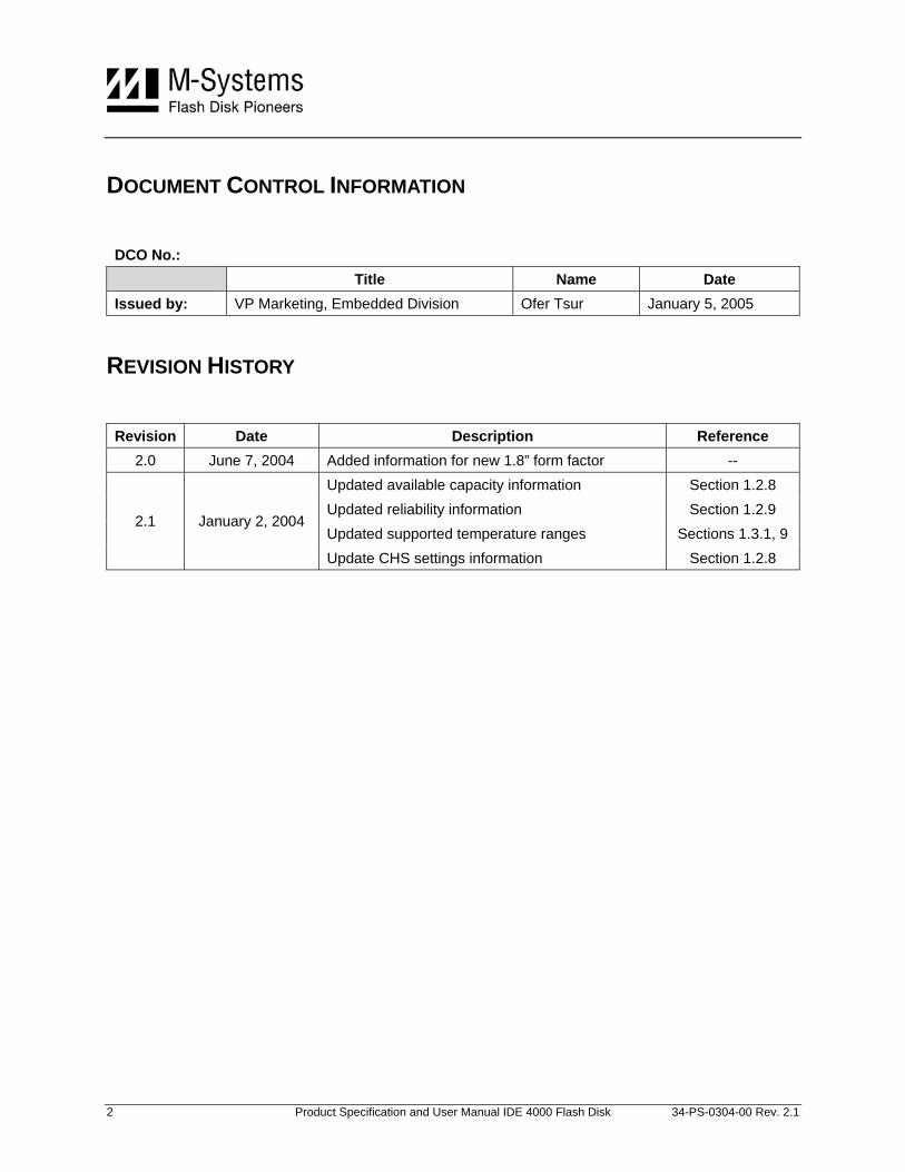
DOCUMENT CONTROL INFORMATION
DCO No.: Title Name Date Issued by: VP Marketing, Embedded Division Ofer Tsur January 5, 2005
REVISION HISTORY
Revision Date Description Reference 2.0 June 7, 2004 Added information for new 1.8” form factor --
Updated available capacity information Section 1.2.8 Updated reliability information Section 1.2.9 Updated supported temperature ranges Sections 1.3.1, 9
2.1 January 2, 2004
Update CHS settings information Section 1.2.8
2 Product Specification and User Manual IDE 4000 Flash Disk 34-PS-0304-00 Rev. 2.1
TABLE OF CONTENTS 1. Specifications........................................................................................................................ 5
1.1. Critical Item Definition .................................................................................................... 5 1.2. Characteristics................................................................................................................5
1.2.1. Interface Definition........................................................................................................... 5 1.2.2. IDE Transfer Modes......................................................................................................... 5 1.2.3. Performance .................................................................................................................... 5 1.2.4. Access Time .................................................................................................................... 6 1.2.5. Seek Time........................................................................................................................ 6 1.2.6. Input Voltage.................................................................................................................... 6 1.2.7. Current Consumption....................................................................................................... 6 1.2.8. Memory Capacity............................................................................................................. 7 1.2.9. Endurance........................................................................................................................ 8 1.2.10. Mean Time Between Failures (MTBF)............................................................................. 8 1.2.11. Physical Characteristics................................................................................................... 8
1.3. Environmental Conditions ............................................................................................ 11 1.3.1. Temperature .................................................................................................................. 11 1.3.2. Altitude ........................................................................................................................... 12 1.3.3. Relative Humidity ........................................................................................................... 12 1.3.4. Shock ............................................................................................................................. 12 1.3.5. Vibration......................................................................................................................... 12 1.3.6. Storage Life and Data Retention ................................................................................... 12
2. Drive Configuration............................................................................................................. 13 3. Interface Connectors .......................................................................................................... 14 4. Supported IDE Commands................................................................................................. 15 5. CE and FCC Compatibility.................................................................................................. 16 6. Label Information................................................................................................................ 17 7. Using the IDE 4000 Flash Disk........................................................................................... 18
7.1. Unpacking the Drive ..................................................................................................... 18 7.2. Handling Instructions.................................................................................................... 18 7.3. Installing the Drive in a PC........................................................................................... 18 7.4. Using the IDE 4000 in an MS-DOS-Based Platform .................................................... 19 7.5. Troubleshooting ........................................................................................................... 19 7.6. How to Get Help........................................................................................................... 20
3 Product Specification and User Manual IDE 4000 Flash Disk 34-PS-0304-00 Rev. 2.1
8. Warranty............................................................................................................................... 21 9. Ordering Information .......................................................................................................... 22 How to Contact Us .................................................................................................................... 23
4 Product Specification and User Manual IDE 4000 Flash Disk 34-PS-0304-00 Rev. 2.1
1. SPECIFICATIONS
1.1. Critical Item Definition The dimensions of the IDE 4000 flash disk enable mounting in a standard 2.5”or 1.8” disk drive bay, as described in Section 1.2.11.
Note: The information written in this document refers to both IDE 4000 2.5” and 1.8” unless otherwise stated.
1.2. Characteristics
1.2.1. Interface Definition
The IDE 4000 supports the commands listed in Section 4, in compliance with ATA4 standards.
1.2.2. IDE Transfer Modes
The IDE 4000 supports the following transfer modes:
• PIO modes 0 through 4
• DMA modes 0 through 2
1.2.3. Performance
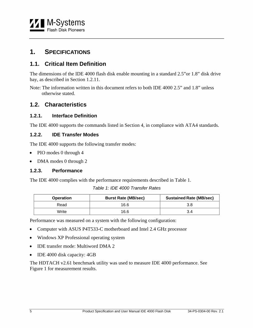
The IDE 4000 complies with the performance requirements described in Table 1. Table 1: IDE 4000 Transfer Rates
Operation Burst Rate (MB/sec) Sustained Rate (MB/sec) Read 16.6 3.8 Write 16.6 3.4
Performance was measured on a system with the following configuration:
• Computer with ASUS P4T533-C motherboard and Intel 2.4 GHz processor
• Windows XP Professional operating system
• IDE transfer mode: Multiword DMA 2
• IDE 4000 disk capacity: 4GB
The HDTACH v2.61 benchmark utility was used to measure IDE 4000 performance. See Figure 1 for measurement results.
5 Product Specification and User Manual IDE 4000 Flash Disk 34-PS-0304-00 Rev. 2.1
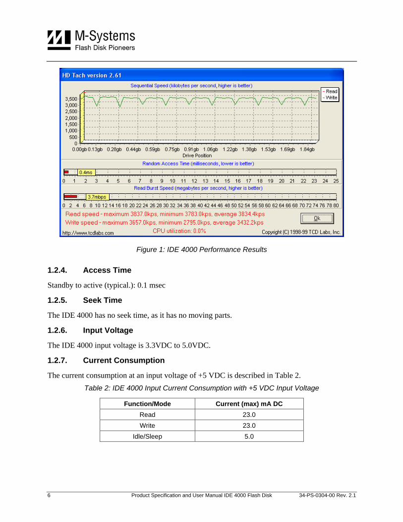
Figure 1: IDE 4000 Performance Results
1.2.4. Access Time
Standby to active (typical.): 0.1 msec
1.2.5. Seek Time
The IDE 4000 has no seek time, as it has no moving parts.
1.2.6. Input Voltage
The IDE 4000 input voltage is 3.3VDC to 5.0VDC.
1.2.7. Current Consumption
The current consumption at an input voltage of +5 VDC is described in Table 2. Table 2: IDE 4000 Input Current Consumption with +5 VDC Input Voltage
Function/Mode Current (max) mA DC Read 23.0 Write 23.0
Idle/Sleep 5.0
6 Product Specification and User Manual IDE 4000 Flash Disk 34-PS-0304-00 Rev. 2.1
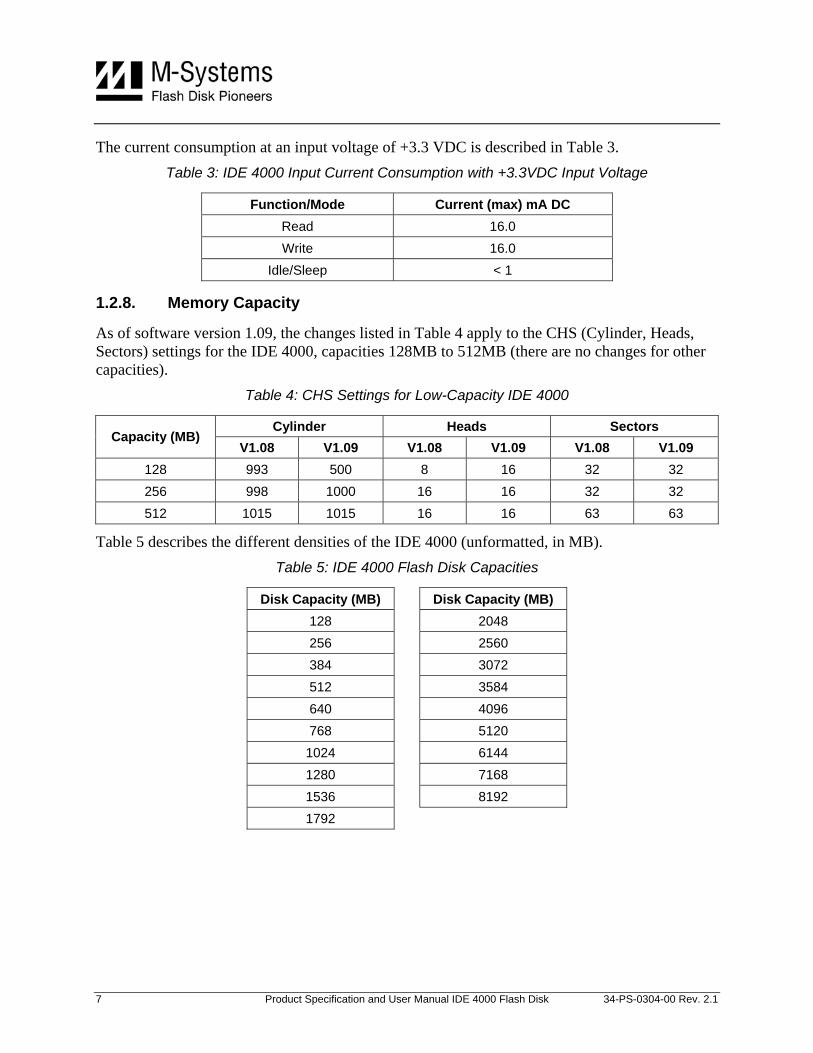
The current consumption at an input voltage of +3.3 VDC is described in Table 3. Table 3: IDE 4000 Input Current Consumption with +3.3VDC Input Voltage
Function/Mode Current (max) mA DC Read 16.0 Write 16.0
Idle/Sleep < 1
1.2.8. Memory Capacity
As of software version 1.09, the changes listed in Table 4 apply to the CHS (Cylinder, Heads, Sectors) settings for the IDE 4000, capacities 128MB to 512MB (there are no changes for other capacities).
Table 4: CHS Settings for Low-Capacity IDE 4000
Cylinder Heads Sectors Capacity (MB)
V1.08 V1.09 V1.08 V1.09 V1.08 V1.09 128 993 500 8 16 32 32 256 998 1000 16 16 32 32 512 1015 1015 16 16 63 63
Table 5 describes the different densities of the IDE 4000 (unformatted, in MB). Table 5: IDE 4000 Flash Disk Capacities
Disk Capacity (MB) Disk Capacity (MB) 128 2048 256 2560 384 3072 512 3584 640 4096 768 5120
1024 6144 1280 7168 1536 8192 1792
7 Product Specification and User Manual IDE 4000 Flash Disk 34-PS-0304-00 Rev. 2.1
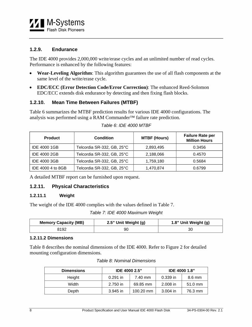
1.2.9. Endurance
The IDE 4000 provides 2,000,000 write/erase cycles and an unlimited number of read cycles. Performance is enhanced by the following features:
• Wear-Leveling Algorithm: This algorithm guarantees the use of all flash components at the same level of the write/erase cycle.
• EDC/ECC (Error Detection Code/Error Correction): The enhanced Reed-Solomon EDC/ECC extends disk endurance by detecting and then fixing flash blocks.
1.2.10. Mean Time Between Failures (MTBF)
Table 6 summarizes the MTBF prediction results for various IDE 4000 configurations. The analysis was performed using a RAM Commander™ failure rate prediction.
Table 6: IDE 4000 MTBF
Product Condition MTBF (Hours) Failure Rate per Million Hours
IDE 4000 1GB Telcordia SR-332, GB, 25°C 2,893,495 0.3456
IDE 4000 2GB Telcordia SR-332, GB, 25°C 2,188,066 0.4570
IDE 4000 3GB Telcordia SR-332, GB, 25°C 1,759,180 0.5684
IDE 4000 4 to 8GB Telcordia SR-332, GB, 25°C 1,470,874 0.6799
A detailed MTBF report can be furnished upon request.
1.2.11. Physical Characteristics
1.2.11.1 Weight
The weight of the IDE 4000 complies with the values defined in Table 7. Table 7: IDE 4000 Maximum Weight
Memory Capacity (MB) 2.5” Unit Weight (g) 1.8” Unit Weight (g) 8192 90 30
1.2.11.2 Dimensions
Table 8 describes the nominal dimensions of the IDE 4000. Refer to Figure 2 for detailed mounting configuration dimensions.
Table 8: Nominal Dimensions
Dimensions IDE 4000 2.5” IDE 4000 1.8” Height 0.291 in 7.40 mm 0.339 in 8.6 mm Width 2.750 in 69.85 mm 2.008 in 51.0 mm Depth 3.945 in 100.20 mm 3.004 in 76.3 mm
8 Product Specification and User Manual IDE 4000 Flash Disk 34-PS-0304-00 Rev. 2.1
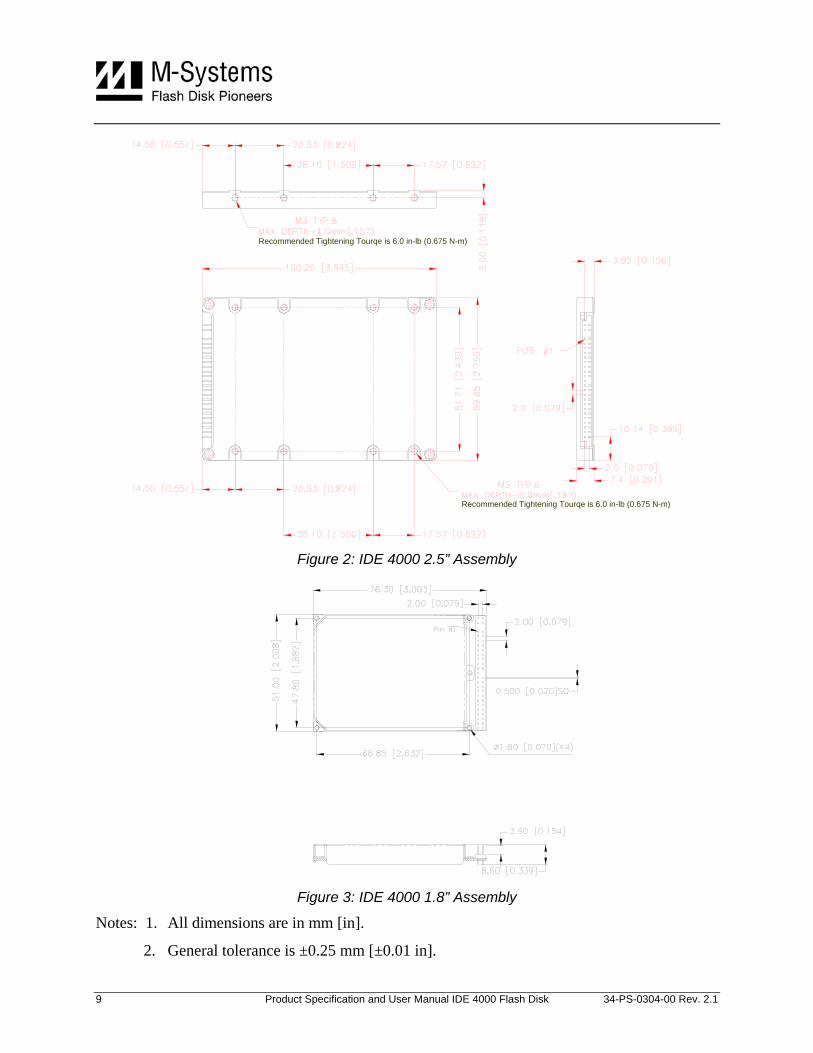
Recommended Tightening Tourqe is 6.0 in-lb (0.675 N-m)
Recommended Tightening Tourqe is 6.0 in-lb (0.675 N-m)
Figure 2: IDE 4000 2.5” Assembly
Figure 3: IDE 4000 1.8” Assembly
Notes: 1. All dimensions are in mm [in].
2. General tolerance is ±0.25 mm [±0.01 in].
9 Product Specification and User Manual IDE 4000 Flash Disk 34-PS-0304-00 Rev. 2.1
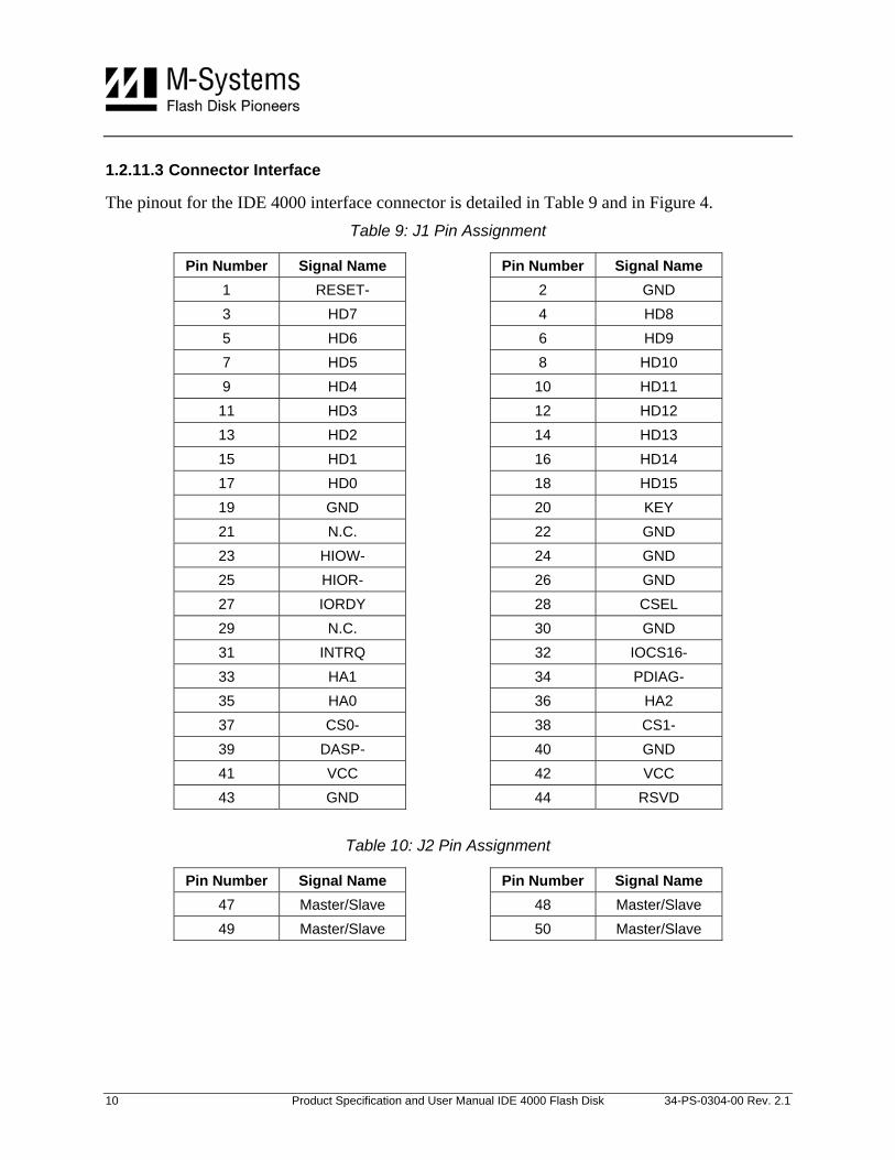
1.2.11.3 Connector Interface
The pinout for the IDE 4000 interface connector is detailed in Table 9 and in Figure 4. Table 9: J1 Pin Assignment
Pin Number Signal Name Pin Number Signal Name 1 RESET- 2 GND 3 HD7 4 HD8 5 HD6 6 HD9 7 HD5 8 HD10 9 HD4 10 HD11 11 HD3 12 HD12 13 HD2 14 HD13 15 HD1 16 HD14 17 HD0 18 HD15 19 GND 20 KEY 21 N.C. 22 GND 23 HIOW- 24 GND 25 HIOR- 26 GND 27 IORDY 28 CSEL 29 N.C. 30 GND 31 INTRQ 32 IOCS16- 33 HA1 34 PDIAG- 35 HA0 36 HA2 37 CS0- 38 CS1- 39 DASP- 40 GND 41 VCC 42 VCC 43 GND 44 RSVD
Table 10: J2 Pin Assignment
Pin Number Signal Name Pin Number Signal Name 47 Master/Slave 48 Master/Slave 49 Master/Slave 50 Master/Slave
10 Product Specification and User Manual IDE 4000 Flash Disk 34-PS-0304-00 Rev. 2.1
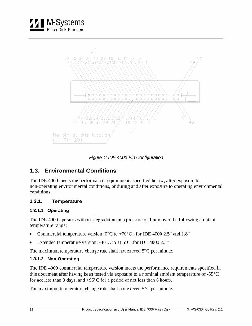
Figure 4: IDE 4000 Pin Configuration
1.3. Environmental Conditions The IDE 4000 meets the performance requirements specified below, after exposure to non-operating environmental conditions, or during and after exposure to operating environmental conditions.
1.3.1. Temperature
1.3.1.1 Operating
The IDE 4000 operates without degradation at a pressure of 1 atm over the following ambient temperature range:
• Commercial temperature version: 0°C to +70°C : for IDE 4000 2.5” and 1.8”
• Extended temperature version: -40°C to +85°C :for IDE 4000 2.5”
The maximum temperature change rate shall not exceed 5°C per minute. 1.3.1.2 Non-Operating
The IDE 4000 commercial temperature version meets the performance requirements specified in this document after having been tested via exposure to a nominal ambient temperature of -55°C for not less than 3 days, and +95°C for a period of not less than 6 hours.
The maximum temperature change rate shall not exceed 5°C per minute.
11 Product Specification and User Manual IDE 4000 Flash Disk 34-PS-0304-00 Rev. 2.1
1.3.1.3 Airflow Requirements
General airflow guideline: 3-5 cu.feet/min.
1.3.2. Altitude
The IDE 4000 sustains full operation at altitudes ranging from sea level to 80,000 feet above sea level. It is also capable of full operation during air transportation via non-pressurized flights at altitudes greater than 80,000 feet above sea level.
1.3.3. Relative Humidity
The IDE 4000 withstands conditions of 8% to 95% non-condensing relative humidity (operation and non-operation).
1.3.4. Shock
The IDE 4000 sustains full operation after being subjected to 1000 G shock testing in the vertical axis.
1.3.5. Vibration
The IDE 4000 remains operational without degradation while being subjected to a 15 G vibration condition.
1.3.6. Storage Life and Data Retention
The IDE 4000 can be placed in non-operational storage in shipping containers or crates for a period of up to 3 years without its capabilities being permanently affected. The IDE 4000 has a data retention span of over 10 years.
12 Product Specification and User Manual IDE 4000 Flash Disk 34-PS-0304-00 Rev. 2.1
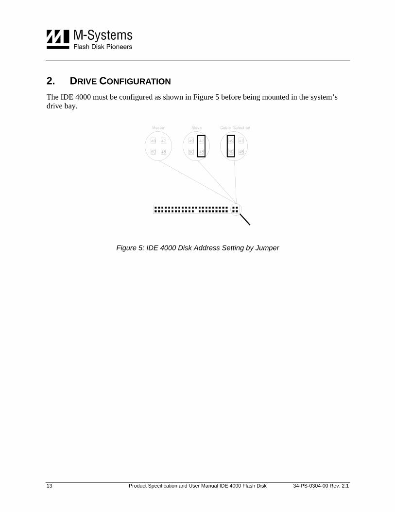
2. DRIVE CONFIGURATION The IDE 4000 must be configured as shown in Figure 5 before being mounted in the system’s drive bay.
Figure 5: IDE 4000 Disk Address Setting by Jumper
13 Product Specification and User Manual IDE 4000 Flash Disk 34-PS-0304-00 Rev. 2.1
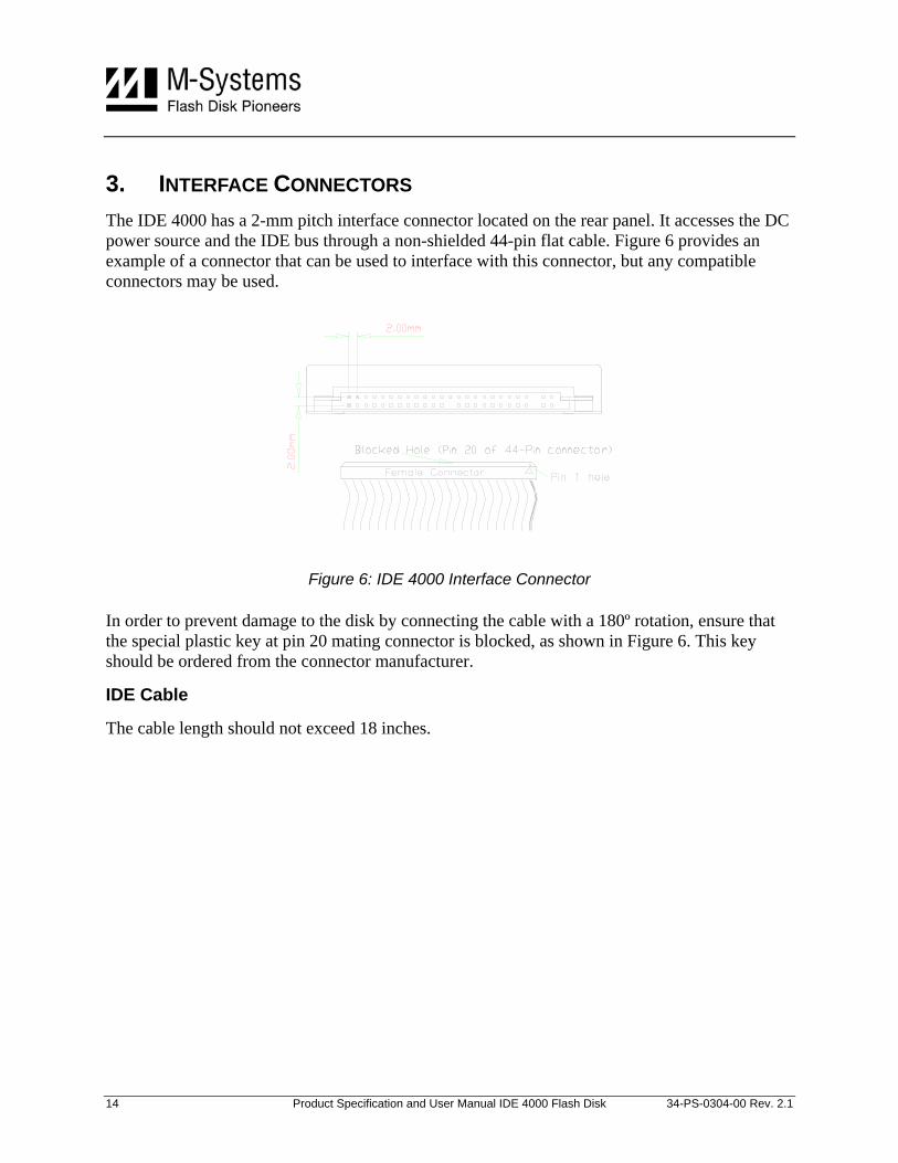
3. INTERFACE CONNECTORS The IDE 4000 has a 2-mm pitch interface connector located on the rear panel. It accesses the DC power source and the IDE bus through a non-shielded 44-pin flat cable. Figure 6 provides an example of a connector that can be used to interface with this connector, but any compatible connectors may be used.
Figure 6: IDE 4000 Interface Connector
In order to prevent damage to the disk by connecting the cable with a 180º rotation, ensure that the special plastic key at pin 20 mating connector is blocked, as shown in Figure 6. This key should be ordered from the connector manufacturer.
IDE Cable
The cable length should not exceed 18 inches.
14 Product Specification and User Manual IDE 4000 Flash Disk 34-PS-0304-00 Rev. 2.1
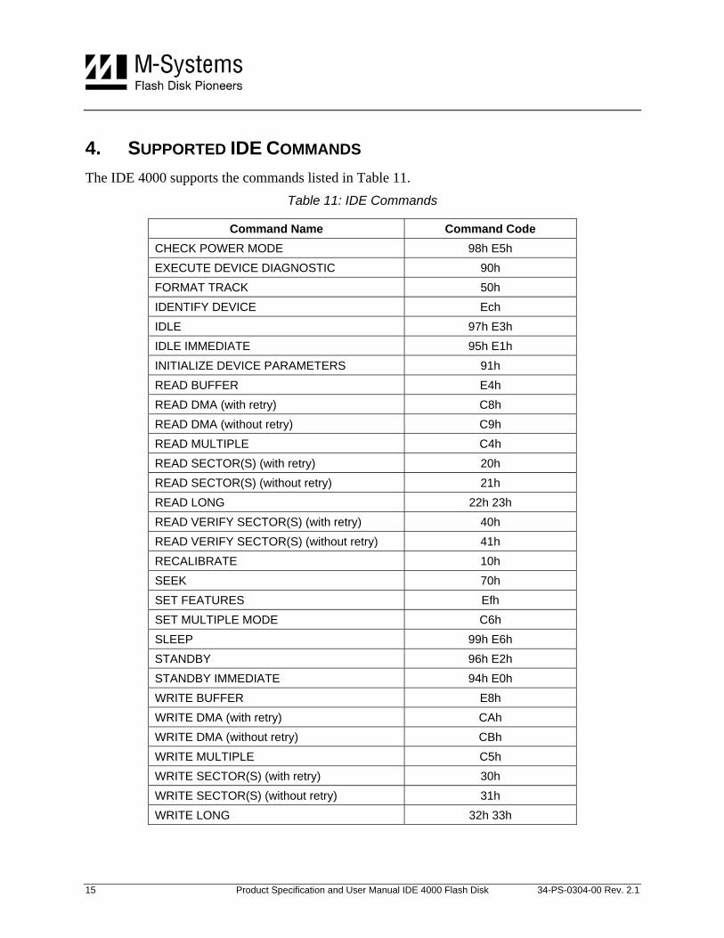
4. SUPPORTED IDE COMMANDS The IDE 4000 supports the commands listed in Table 11.
Table 11: IDE Commands
Command Name Command Code CHECK POWER MODE 98h E5h EXECUTE DEVICE DIAGNOSTIC 90h FORMAT TRACK 50h IDENTIFY DEVICE Ech IDLE 97h E3h IDLE IMMEDIATE 95h E1h INITIALIZE DEVICE PARAMETERS 91h READ BUFFER E4h READ DMA (with retry) C8h READ DMA (without retry) C9h READ MULTIPLE C4h READ SECTOR(S) (with retry) 20h READ SECTOR(S) (without retry) 21h READ LONG 22h 23h READ VERIFY SECTOR(S) (with retry) 40h READ VERIFY SECTOR(S) (without retry) 41h RECALIBRATE 10h SEEK 70h SET FEATURES Efh SET MULTIPLE MODE C6h SLEEP 99h E6h STANDBY 96h E2h STANDBY IMMEDIATE 94h E0h WRITE BUFFER E8h WRITE DMA (with retry) CAh WRITE DMA (without retry) CBh WRITE MULTIPLE C5h WRITE SECTOR(S) (with retry) 30h WRITE SECTOR(S) (without retry) 31h WRITE LONG 32h 33h
15 Product Specification and User Manual IDE 4000 Flash Disk 34-PS-0304-00 Rev. 2.1
5. CE AND FCC COMPATIBILITY The IDE 4000 complies with the following CE requirements and FCC standards:
• FCC Part 15 Class B
• EN 55022 Class B, CISPR 22 Class B (MIC)
• V-3/2001.04 Class B (Japan), AS/NZS 3548 Class B (Australia/NZ)
• BSMI CNS 13438 Class B (Taiwan)
• CAN/CSA-CISPR 22-96 Class B (Canada) CFR 47 FCC Class B
• EN 55024, EN 61000 (EMC)
16 Product Specification and User Manual IDE 4000 Flash Disk 34-PS-0304-00 Rev. 2.1
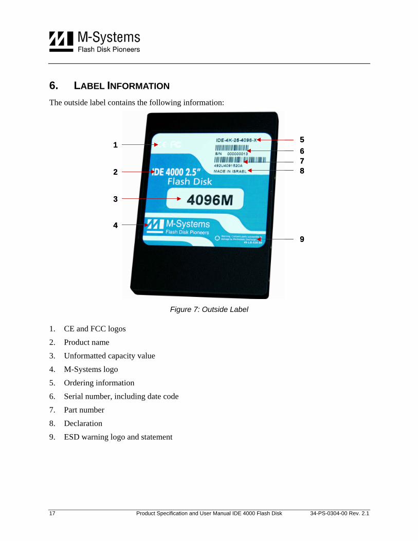
6. LABEL INFORMATION The outside label contains the following information:
1
3
4
5678
9
2
1
3
4
5678
9
2
Figure 7: Outside Label
1. CE and FCC logos
2. Product name
3. Unformatted capacity value
4. M-Systems logo
5. Ordering information
6. Serial number, including date code
7. Part number
8. Declaration
9. ESD warning logo and statement
17 Product Specification and User Manual IDE 4000 Flash Disk 34-PS-0304-00 Rev. 2.1
7. USING THE IDE 4000 FLASH DISK The IDE 4000 is shipped with the following components:
• Warranty certificate indicating M-Systems’ 36-month warranty
• Four screws and one jumper, in kit no. 48-PK-001-00
If any of these items is missing, please contact your dealer.
7.1. Unpacking the Drive Before unpacking or handling a drive, take all proper electrostatic discharge (ESD) precautions, including personnel and equipment grounding.
Before you begin installing the IDE 4000 in your system, perform a visual inspection and follow the recommendations below:
• If the shipping container appears to be damaged or water-stained, notify your dealer.
• Remove the disk from its shipping enclosure and inspect it for any damage that may have occurred during shipment. If any damage is observed, notify your dealer.
• Record the disk serial number and shipment date.
• Retain the original shipping enclosure and all packing material for re-shipment.
7.2. Handling Instructions You can prolong the life of your IDE 4000, increase its reliability, and prevent unnecessary damage by following the instructions listed below. Failure to follow any of these instructions may void your warranty.
• Always take all proper electrostatic discharge (ESD) precautions, including personnel and equipment grounding.
• Always operate the flash disk within the environmental specifications.
• Always use a grounded wrist strap when handling the flash disk.
• Never switch DC power to the drive by plugging an electrically live source cable into the drive’s power connector.
• Pay attention to the cable polarity whenever connecting the drive to the cable.
7.3. Installing the Drive in a PC To install the IDE 4000: 1. Power off the PC and remove the cover.
2. Configure the IDE 4000 jumper settings according to the information provided in Section 2.
18 Product Specification and User Manual IDE 4000 Flash Disk 34-PS-0304-00 Rev. 2.1
3. Connect a 44-pin ribbon cable between the IDE 4000 and the adapter. Make sure to orient the cable so that pin 1 of the IDE 4000 is connected to pin 1 of the host adapter.
4. Mount the IDE 4000 in a free drive bay.
5. Close the PC cover and power on the PC.
The host BIOS sign-on message appears and displays a key sequence to enter the BIOS setup. Set up the BIOS to recognize the IDE 4000.
7.4. Using the IDE 4000 in an MS-DOS-Based Platform After installing the IDE 4000, it must be installed as a disk drive under DOS. Run the DOS commands listed below and follow the instructions displayed for each command. For more information regarding DOS commands, refer to your DOS manual.
• Run the DOS FDISK program to partition the IDE 4000.
• Run the DOS FORMAT command to high-level format the IDE 4000.
• If you want the IDE 4000 to be a bootable drive, run the DOS SYS command and change the partition to active.
7.5. Troubleshooting The problems that arise in most installations can be summarized below:
Cables:
• Homemade, short, flat ribbon cables with bad contacts or cheap cables
• Mixing round cables with flat cables.
Cable Length:
• The cable exceeds the length specified in the standard
• Cables are too long to support the transfer rate.
Device Address Conflict:
• A new device was added with an IDE setting identical to an existing device on the bus.
• Connection problems.
• A cable was connecting with reverse polarity.
19 Product Specification and User Manual IDE 4000 Flash Disk 34-PS-0304-00 Rev. 2.1
7.6. How to Get Help If you need technical assistance with the installation and configuration of your IDE 4000, please contact your customer support representative and have the following information available:
• Product and serial number of your IDE 4000
• Description of your computer hardware (manufacturer, model, attached devices, etc.)
• Description of your IDE host adapter and associated drivers
• Description of your software (operating system, version, application software, etc.)
• A complete description of the problem
• The exact wording of any error messages
Before contacting M-Systems directly, first contact your dealer (if you did not purchase you IDE 4000 directly from M-Systems). If your dealer cannot provide the help you need, you can obtain technical support directly from M-Systems at one of the numbers in the list of offices on the last page of this manual, or from the M-Systems website www.m-systems.com.
20 Product Specification and User Manual IDE 4000 Flash Disk 34-PS-0304-00 Rev. 2.1
8. WARRANTY The warranty period of the IDE 4000 is 36 months (3 years). For details, please refer to the warranty certificate, which is included with the IDE 4000.
21 Product Specification and User Manual IDE 4000 Flash Disk 34-PS-0304-00 Rev. 2.1
9. ORDERING INFORMATION Ordering information for the IDE 4000 2.5”: IDE-4K-25-CCCC-T
Ordering information for the IDE 4000 1.8”: IDE-4K-18-CCCC-T
Where:
CCCC: Capacity (MB) 128, 256, 384, 512, 640, 768, 1024, 1280, 1536, 1792, 2048, 2560, 3072, 3584, 4096, 5120, 6144, 7168, 8192
T: Temperature Range Blank
X Commercial: 0°C to +70°C (for 2.5” and 1.8”)
Extended: -40°C to +85°C (for 2.5” only)
Note: the IDE 4000 in a 1.8” casing is available only in commercial temperature range.
22 Product Specification and User Manual IDE 4000 Flash Disk 34-PS-0304-00 Rev. 2.1
HOW TO CONTACT US USA M-Systems Inc. 555 North Mathilda Avenue, Suite 220 Sunnyvale, CA 94085 Phone: +1-408-470-4440 Fax: +1-408-470-4470
China M-Systems China Ltd. Room 121-122 Bldg. 2, International Commerce & Exhibition Ctr. Hong Hua Rd. Futian Free Trade Zone Shenzhen, China Phone: +86-755-8348-5218 Fax: +86-755-8348-5418
Europe M-Systems Ltd. 7 Atir Yeda St. Kfar Saba 44425, Israel Tel: +972-9-764-5000 Fax: +972-3-548-8666
Internet www.m-systems.com
General Information [email protected]
Japan M-Systems Japan Inc. Asahi Seimei Gotanda Bldg., 3F 5-25-16 Higashi-Gotanda Shinagawa-ku Tokyo, 141-0022 Phone: +81-3-5423-8101 Fax: +81-3-5423-8102
Taiwan M-Systems Asia Ltd. 14 F, No. 6, Sec. 3 Minquan East Road Taipei, Taiwan, 104 Tel: +886-2-2515-2522 Fax: +886-2-2515-2295 Sales and Technical Information
This document is for information use only and is subject to change without prior notice. M-Systems Flash Disk Pioneers Ltd. assumes no responsibility for any errors that may appear in this document. No part of this document may be reproduced, transmitted, transcribed, stored in a retrievable manner or translated into any language or computer language, in any form or by any means, electronic, mechanical, magnetic, optical, chemical, manual or otherwise, without prior written consent of M-Systems.
M-Systems products are not warranted to operate without failure. Accordingly, in any use of the Product in life support systems or other applications where failure could cause injury or loss of life, the Product should only be incorporated in systems designed with appropriate and sufficient redundancy or backup features.
Contact your local M-Systems sales office or distributor, or visit our website at www.m-systems.com to obtain the latest specifications before placing your order.
© 2005 M-Systems Flash Disk Pioneers Ltd. All rights reserved.
M-Systems, DiskOnChip, DiskOnChip Millennium, DiskOnKey, DiskOnKey MyKey, FFD, Fly-By, iDiskOnChip, iDOC, mDiskOnChip, mDOC, Mobile DiskOnChip, Smart DiskOnKey, SmartCaps, SuperMAP, TrueFFS, uDiskOnChip, uDOC, and Xkey are trademarks or registered trademarks of M-Systems Flash Disk Pioneers, Ltd. Other product names or service marks mentioned herein may be trademarks or registered trademarks of their respective owners and are hereby acknowledged. All specifications are subject to change without prior notice.
23 Product Specification and User Manual IDE 4000 Flash Disk 34-PS-0304-00 Rev. 2.1