Embed Size (px)
Citation preview
ROP TC Initial Ballot Cover Memo – September 24, 2010
National Fire Protection Association
1 Batterymarch Park, Quincy, MA 02169-7471
Phone: 617-770-3000 • Fax: 617-770-0700 • www.nfpa.org
M E M O R A N D U M
TO: NFPA Technical Committee on Emergency Medical Services
Protective Clothing and Equipment
FROM: David Trebisacci, Staff Liaison
DATE: July 27, 2011
SUBJECT: NFPA 1999 ROP TC Letter Ballot (F2012)
___________________________________________________________
The ROP letter ballot for NFPA 1999 is attached. The ballot is for formally voting on
whether or not you concur with the committee’s actions on the proposals. Reasons must
accompany all negative and abstention ballots.
Please do not vote negatively because of editorial errors. However, please bring
such errors to my attention for action.
Please complete and return your ballot as soon as possible but no later than August 18,
2011. As noted on the ballot form, please return the ballot to Yvonne Smith either via e-
mail to [email protected] or via fax to 617-984-7056. You may also mail your ballot to
the attention of Yvonne Smith at NFPA, 1 Batterymarch Park, Quincy, MA 02169.
The return of ballots is required by the Regulations Governing Committee Projects.
Attachments: Proposals
Letter Ballot

Report on Proposals – November 2012 NFPA 1999_______________________________________________________________________________________________1999-1 Log #CP1 FAE-EMS
_______________________________________________________________________________________________Technical Committee on Emergency Medical Services Protective Clothing and Equipment,
Review entire document to: 1) Update any extracted material by preparing separate proposals todo so, and 2) review and update references to other organizations documents, by preparing proposal(s) as required.
To conform to the NFPA Regulations Governing Committee Projects.
The technical committee reviewed the entire document to update any extracted material andprepared separate proposals to do so. The TC also reviewed and updated references to other organizations'documents, and prepared separate proposal(s) as required.
_______________________________________________________________________________________________1999-2 Log #CP3 FAE-EMS
_______________________________________________________________________________________________Technical Committee on Emergency Medical Services Protective Clothing and Equipment,
Incorporate changes in certification, product labeling, design requirements, performancerequirements, and test methods for consistency with other standards related to personal protective equipment that arepart of the Project on Fire and Emergency Services Protective Clothing and Equipment.
The committee wants to harmonize requirements where appropriate with related standards forconsistency of evaluation and testing approaches.
The technical committee will prepare proposals and provide text to correlate and harmonizerequirements where appropriate with related standards for consistency of evaluation and testing approaches.
1Printed on 7/26/2011

Report on Proposals – November 2012 NFPA 1999_______________________________________________________________________________________________1999-3 Log #CP4 FAE-EMS
_______________________________________________________________________________________________Technical Committee on Emergency Medical Services Protective Clothing and Equipment,
Update referenced publications as follows (unchanged standards in the current edition are notincluded):
NFPA 1581, 2005 2010 edition.NFPA 1994, 2007 2012 edition.
AATCC 22, , 2005 2010.AATCC 42, , 2000 2007.AATCC 61, , 2010.AATCC 70, 2005 2010.AATCC 135, , 2004 2010.
ANSI/ISEA 107, , 2004 2010.ANSI/ASSE Z87.1, , 20032010.ANSI/ISEA Z89.1, 2009.
ASTM B 117, , 2003 2009.ASTM D 412a,
1998a (2002) e1 2006 ae2.ASTM D 573, 2004 (2010).ASTM D 1230, , 1994 (2000) 2010.ASTM D 1630, 2006.ASTM D 1683, 2004 2011.ASTM D 1776, 2004 2008 e1.ASTM D 2582,
2003 2009.ASTM D 3787, , 2001 2007
(2011).ASTM D 3884,
2001 e1 2009.ASTM D 4157, , 2002
2010.ASTM D 4966,
1998 (2004) 2010.ASTM D 5034, , 1995 (2001)
2009.ASTM D 5151, 1999 2006.ASTM D 5169, , 1998
(2010).ASTM D 5170, , 1998 (2010).ASTM D 5587, , 2005 2008.ASTM D 5712,
2005, e1 2010.ASTM E 809, 2002 2008.ASTM E 991, 1998 2011.ASTM E 1164, , 2002 2009a.ASTM E 2152,
2001 (2006).ASTM E 2153, 2001
(2006).ASTM F 392, , 2004 2011.
2Printed on 7/26/2011

Report on Proposals – November 2012 NFPA 1999ASTM F 489,
, 1996.ASTM F 739a,
2007ASTM F 1154,
2010ASTM F 1359,ASTM F 1359a,
1999 2007.ASTM F 1671,
2003 2007.ASTM F 1862,
2005 2007.ASTM F 1868,
, 2002 2009.ASTM F 2100, , 2004 2011.
ASTM F 2010,, 2005 2010.
ASTM F 2412, , 2005.ASTM F 2413, , 2005 2011.
EN 455-2, , 2000 2006.
ISO 62, 1996.ISO 4649,
, 2010.ISO 9001, 2000.ISO 9001,
, 1994.ISO 13287, , 2006.ISO 17011, 2004.ISO/IEC 17021,
2011.ISO 17025, 1999 2005.
A-A-55126B, , 1999 2006.A-A-55634A, , 2004.MIL-F-10884G, , 16 June 1995.
, 11th edition, Merriam-Webster, Inc., Springfield, MA, 2003.
The technical committee is providing updated information on referenced documents.
3Printed on 7/26/2011

Report on Proposals – November 2012 NFPA 1999_______________________________________________________________________________________________1999-4 Log #CP11 FAE-EMS
_______________________________________________________________________________________________Technical Committee on Emergency Medical Services Protective Clothing and Equipment,
Remove the following reference from Chapter 2:
ASTM F 2412, , 2005.Add a new design requirement as follows:
Footwear shall meet the performance requirements as specified in ASTM F2413,, for Impact, Compression, and Puncture Resistant Footwear with the exception
that Flex Resistance to Cracking shall not be evaluated.Delete the following performance requirements:
Footwear soles and heels shall be tested for physical penetration resistance as specified in Section 8.20,Puncture Resistance Test Two, and shall meet the Section 5.7.4 requirements for puncture resistant footwear asspecified in ASTM F 2413, .
Footwear toes shall be tested for resistance to impact and compression as specified in Section 8.23, Impactand Compression Resistance Test, and shall meet the Class 50 requirements in 5.1.4.1(3) and (4) requirements forimpact resistance and 5.2.3.1(3) and (4) for compression resistance as specified in ASTM F 2413,
.Delete test methods in Section 8.20 and 8.23 as follows:
This test method shall apply to emergency medical footwear soles.A minimum of three footwear soles shall be tested.
Samples for conditioning shall be footwear sole sections.Specimens shall be conditioned as specified in 8.1.2.
Puncture resistance testing shall be performed in accordance with Section 11 for punctureresistance of ASTM F 2412, Standard Test Methods for Foot Protection.
The force required to puncture the sole reinforcement device of each specimen shall be recorded andreported.
One or more footwear specimens failing this test shall constitute failing performance.
This test method shall apply to the toe section of emergency medical footwear.A minimum of three footwear items shall be tested for both impact and compression.
Samples for conditioning shall be complete footwear toes.Specimens shall be conditioned as specified in 8.1.2.
Footwear specimens shall be tested in accordance with Section 5 for impact resistance and Section6 for compression resistance of ASTM F 2412,
The impact and compression forces for each specimen shall be recorded and reported.One or more footwear specimens failing this test shall constitute failing performance.
These change actions align NFPA 1999 with the footwear requirements with other standards in theproject. There is no longer a Class 50 level of performance for either impact or compression resistance.
4Printed on 7/26/2011
Report on Proposals – November 2012 NFPA 1999_______________________________________________________________________________________________1999-5 Log #CP13 FAE-EMS
_______________________________________________________________________________________________Technical Committee on Emergency Medical Services Protective Clothing and Equipment,
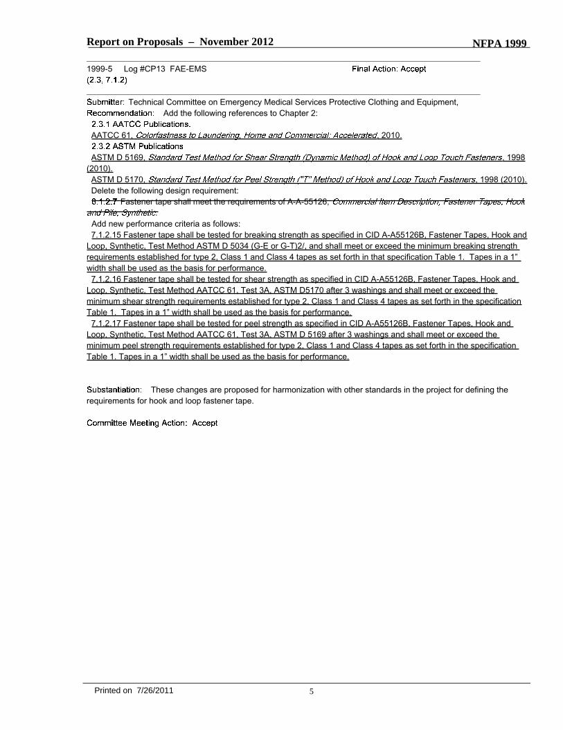
Add the following references to Chapter 2:
AATCC 61, , 2010.
ASTM D 5169, , 1998(2010).ASTM D 5170, , 1998 (2010).Delete the following design requirement:
Fastener tape shall meet the requirements of A-A-55126,.
Add new performance criteria as follows:7.1.2.15 Fastener tape shall be tested for breaking strength as specified in CID A-A55126B, Fastener Tapes, Hook and
Loop, Synthetic, Test Method ASTM D 5034 (G-E or G-T)2/, and shall meet or exceed the minimum breaking strengthrequirements established for type 2, Class 1 and Class 4 tapes as set forth in that specification Table 1. Tapes in a 1”width shall be used as the basis for performance.7.1.2.16 Fastener tape shall be tested for shear strength as specified in CID A-A55126B, Fastener Tapes, Hook and
Loop, Synthetic, Test Method AATCC 61, Test 3A, ASTM D5170 after 3 washings and shall meet or exceed theminimum shear strength requirements established for type 2, Class 1 and Class 4 tapes as set forth in the specificationTable 1. Tapes in a 1” width shall be used as the basis for performance.7.1.2.17 Fastener tape shall be tested for peel strength as specified in CID A-A55126B, Fastener Tapes, Hook and
Loop, Synthetic, Test Method AATCC 61, Test 3A, ASTM D 5169 after 3 washings and shall meet or exceed theminimum peel strength requirements established for type 2, Class 1 and Class 4 tapes as set forth in the specificationTable 1. Tapes in a 1” width shall be used as the basis for performance.
These changes are proposed for harmonization with other standards in the project for defining therequirements for hook and loop fastener tape.
5Printed on 7/26/2011
Report on Proposals – November 2012 NFPA 1999_______________________________________________________________________________________________1999-6 Log #CP10 FAE-EMS
_______________________________________________________________________________________________Technical Committee on Emergency Medical Services Protective Clothing and Equipment,
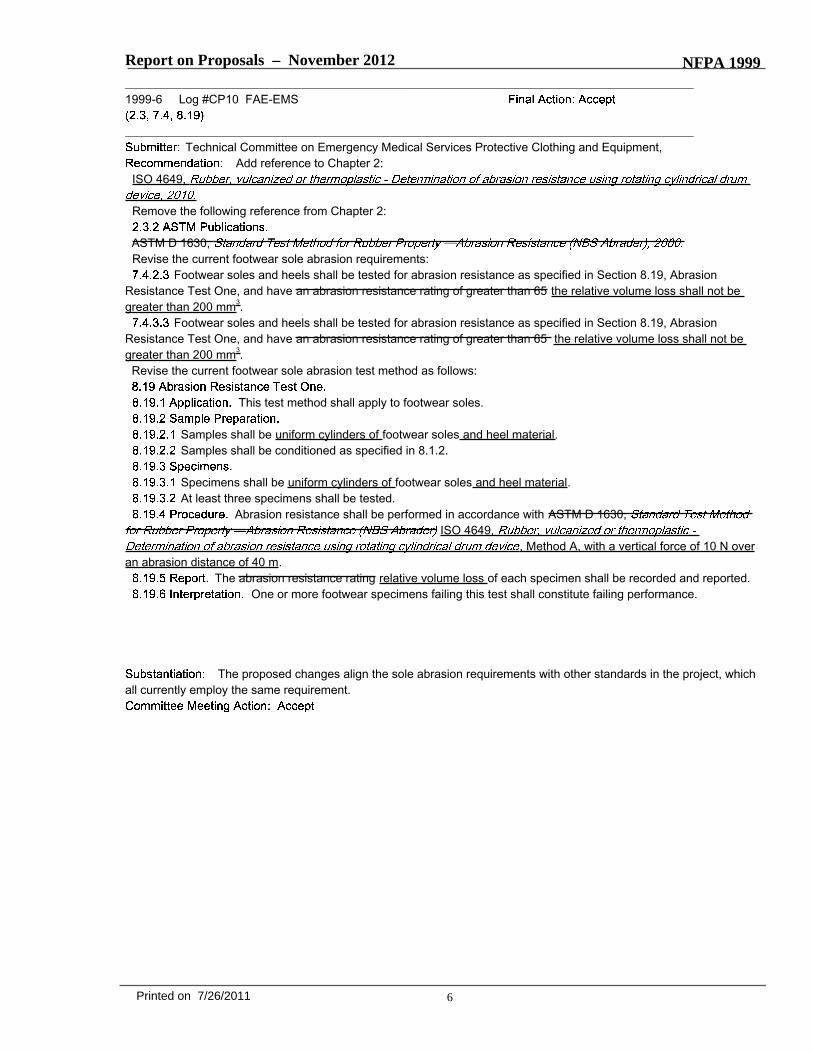
Add reference to Chapter 2:ISO 4649,
Remove the following reference from Chapter 2:
ASTM D 1630,Revise the current footwear sole abrasion requirements:
Footwear soles and heels shall be tested for abrasion resistance as specified in Section 8.19, AbrasionResistance Test One, and have an abrasion resistance rating of greater than 65 the relative volume loss shall not begreater than 200 mm3.
Footwear soles and heels shall be tested for abrasion resistance as specified in Section 8.19, AbrasionResistance Test One, and have an abrasion resistance rating of greater than 65 the relative volume loss shall not begreater than 200 mm3.Revise the current footwear sole abrasion test method as follows:
This test method shall apply to footwear soles.
Samples shall be uniform cylinders of footwear soles and heel material.Samples shall be conditioned as specified in 8.1.2.
Specimens shall be uniform cylinders of footwear soles and heel material.At least three specimens shall be tested.
Abrasion resistance shall be performed in accordance with ASTM D 1630,ISO 4649,
, Method A, with a vertical force of 10 N overan abrasion distance of 40 m.
The abrasion resistance rating relative volume loss of each specimen shall be recorded and reported.One or more footwear specimens failing this test shall constitute failing performance.
The proposed changes align the sole abrasion requirements with other standards in the project, whichall currently employ the same requirement.
6Printed on 7/26/2011
Report on Proposals – November 2012 NFPA 1999_______________________________________________________________________________________________1999-7 Log #CP8 FAE-EMS
_______________________________________________________________________________________________Technical Committee on Emergency Medical Services Protective Clothing and Equipment,
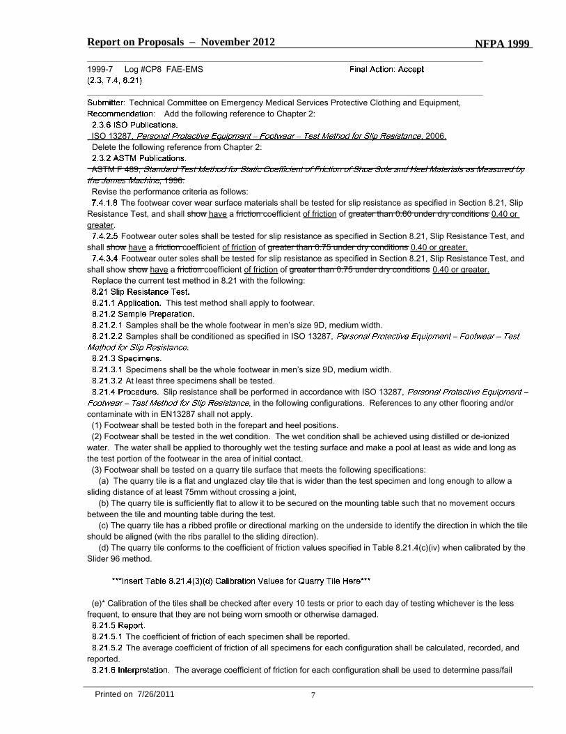
Add the following reference to Chapter 2:
ISO 13287, , 2006.Delete the following reference from Chapter 2:
ASTM F 489,, 1996.
Revise the performance criteria as follows:The footwear cover wear surface materials shall be tested for slip resistance as specified in Section 8.21, Slip
Resistance Test, and shall show have a friction coefficient of friction of greater than 0.60 under dry conditions 0.40 orgreater.
Footwear outer soles shall be tested for slip resistance as specified in Section 8.21, Slip Resistance Test, andshall show have a friction coefficient of friction of greater than 0.75 under dry conditions 0.40 or greater.
Footwear outer soles shall be tested for slip resistance as specified in Section 8.21, Slip Resistance Test, andshall show show have a friction coefficient of friction of greater than 0.75 under dry conditions 0.40 or greater.Replace the current test method in 8.21 with the following:
This test method shall apply to footwear.
Samples shall be the whole footwear in men’s size 9D, medium width.Samples shall be conditioned as specified in ISO 13287,
.
Specimens shall be the whole footwear in men’s size 9D, medium width.At least three specimens shall be tested.
Slip resistance shall be performed in accordance with ISO 13287,, in the following configurations. References to any other flooring and/or
contaminate with in EN13287 shall not apply.(1) Footwear shall be tested both in the forepart and heel positions.(2) Footwear shall be tested in the wet condition. The wet condition shall be achieved using distilled or de-ionized
water. The water shall be applied to thoroughly wet the testing surface and make a pool at least as wide and long asthe test portion of the footwear in the area of initial contact.(3) Footwear shall be tested on a quarry tile surface that meets the following specifications:
(a) The quarry tile is a flat and unglazed clay tile that is wider than the test specimen and long enough to allow asliding distance of at least 75mm without crossing a joint,
(b) The quarry tile is sufficiently flat to allow it to be secured on the mounting table such that no movement occursbetween the tile and mounting table during the test.
(c) The quarry tile has a ribbed profile or directional marking on the underside to identify the direction in which the tileshould be aligned (with the ribs parallel to the sliding direction).
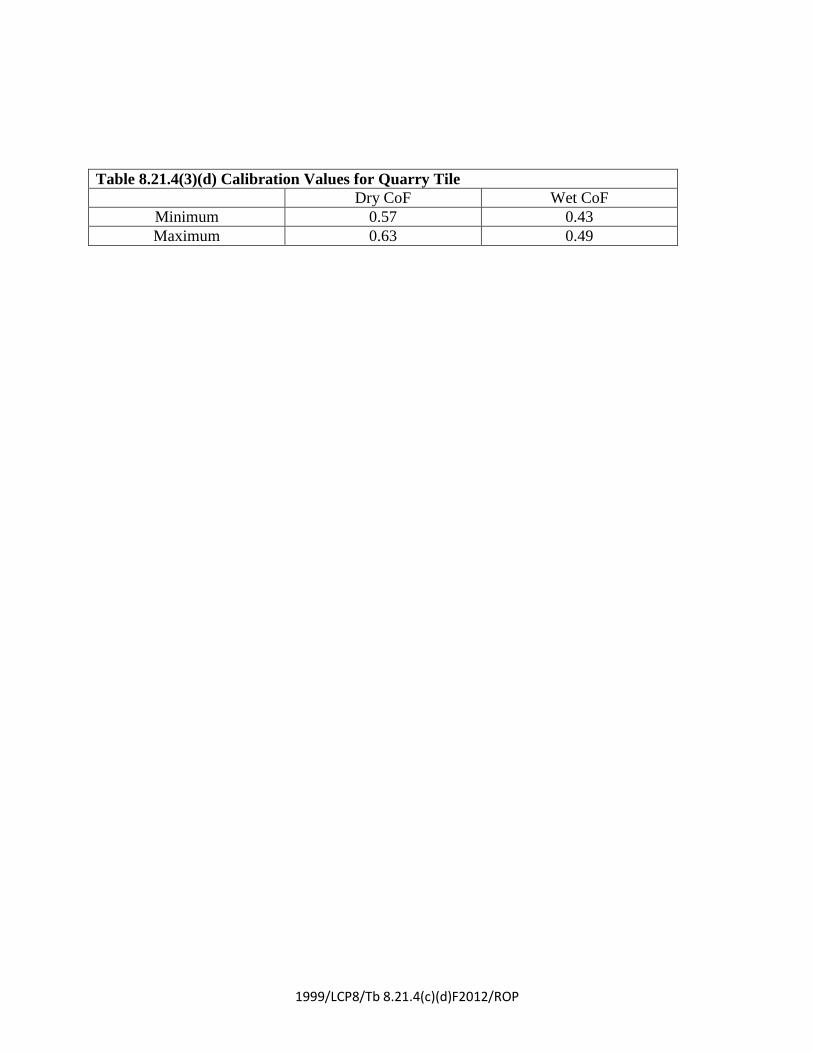
(d) The quarry tile conforms to the coefficient of friction values specified in Table 8.21.4(c)(iv) when calibrated by theSlider 96 method.
(e)* Calibration of the tiles shall be checked after every 10 tests or prior to each day of testing whichever is the lessfrequent, to ensure that they are not being worn smooth or otherwise damaged.
The coefficient of friction of each specimen shall be reported.The average coefficient of friction of all specimens for each configuration shall be calculated, recorded, and
reported.The average coefficient of friction for each configuration shall be used to determine pass/fail
7Printed on 7/26/2011
Report on Proposals – November 2012 NFPA 1999performance.Add following paragraph to Appendix A:
However, if experience shows that the friction properties of the test floor are not strongly influenced byrepeated testing then calibration intervals may be extended.
he proposed changes to the performance criteria and test method to align the procedures with otherstandards in the project.
_______________________________________________________________________________________________1999-8 Log #18 FAE-EMS
_______________________________________________________________________________________________Tim J. Gardner, 3M Company
2.3.2 (add reference)ANSI 207-2006
The authority having jurisdiction should conduct a risk assessment and make the determination for the levelof visibility required in an ensemble or protective clothing for emergency medical incidents operations based upon theanticipated use of such garments. Federal regulation 23 CFR 634 The Federal Highway Administration (FHWA)
(MUTCD), 2009 edition, requires workers on the right-of-way of a Federal-aidhighway all roadways who are exposed to traffic or heavy equipment to wear high visibility apparel that is defined ascompliant to ANSI 107-201004 performance Class 2 or Class 3. It is possible to be compliant with Federal high visibilityregulation 23 CFR 634 the MUTCD either by incorporating ANSI-compliant high visibility fluorescent and retroreflectivematerials into NFPA 1999 compliant apparel such as a jacket, parka, shirt, and so on, or through the use of asupplemental high visibility garment. High visibility component materials incorporated into primary apparel shouldcomply with the requirements of prevailing standards applying to the chosen ensemble, such as NFPA 1999, ANSI 107,and so on. At the time, this compliance to ANSI 207-2006 is not sufficient to meet the requirements of 23 CFR part 634.The MUTCD also allows for the use of ANSI/ISEA 207 assupplemental garments for public safety workers. Where the authority having jurisdiction anticipates the presence ofhazards to personnel due to lack of visibility such as from proximity to traffic, moving machinery, or heavy equipment inoperation, high visibility clothing such as specified in ANSI/ISEA 107, as acompliant garment, or ANSI/ISEA 207 , is the type of garment that shouldbe used. A useful guide for determining appropriate application of Class 1, Class 2 , and Class 3 visibility can be foundin ANSI/ISEA 107, Appendix B, . Labeling of primary orsupplemental apparel complying with ANSI/ISEA 107 specifications should be in accordance with 11.2 of ANSI/ISEA107. Users of protective garments should be aware that visibility markings have varying durability under field useconditions. The visibility materials can be damaged, but still appear to be in good condition or can become soiled andlose retroreflective or fluorescent qualities. Such visibility markings can also lose retroreflective qualities in rain.
Since the last revision of the NFPA 1999 standard, the implementation of Federal worker high visibilityregulations have changed. This proposal updates relevant text in the standard to be consistent with current regulatorylanguage.
8Printed on 7/26/2011
1999/LCP8/Tb 8.21.4(c)(d)F2012/ROP
Table 8.21.4(3)(d) Calibration Values for Quarry Tile
Dry CoF Wet CoF
Minimum 0.57 0.43
Maximum 0.63 0.49
Report on Proposals – November 2012 NFPA 1999_______________________________________________________________________________________________1999-9 Log #CP12 FAE-EMS
_______________________________________________________________________________________________Technical Committee on Emergency Medical Services Protective Clothing and Equipment,
Add the following definitions:The part of the protective footwear that is a relatively flexible material joining the footwear upper
(quarter) and the tongue, which is intended to provide expansion of the footwear front to enable donning of the footwearwhile maintaining continuous moisture integrity of the footwear.
The gusset generally lacks some layers used in the construction of the footwear upper or may includedifferent layers for the purpose of being flexible. The gusset is not observable from the front of the footwear when thefootwear is donned or laced up.
The part of the protective footwear that is provided for protective footwear with a closure that extendsfrom the vamp to the top line of the footwear between sides of the footwear upper and is exposed to the exteriorenvironment when the footwear is correctly donned.
The tongue may or may not be made of the same composite as the footwear upper. The tongue maybe of a similar material composite as the footwear gusset.
Revise the following paragraphs as indicated:Footwear height shall be a minimum of 100 mm (4 in.) when measured according to 6.4.2.3.1 and 6.4.2.3.2
through 6.4.2.3.4.The footwear height shall be determined by measuring inside the boot footwear from the center of the insole
at the heel up to a perpendicular reference line extending across the width of the footwear, at the highest point offootwear excluding pull-on loops at the lowest point of the topline, excluding the tongue and gusset.
Moisture protection shall be continuous circumferentially to within 50 mm (2 in.) of the footwear topline at alllocations, with the exception of the area inside of and within 13 mm (0.5 in.) around pull up holes which fully penetratethe footwear from outside to inside. The height of physical and moisture protection at all locations of the boot shall beno less than 100 mm (4.0 in.) when measured as described in 6.4.2.3.1.
Physical protection shall be continuous circumferentially to within 50 mm (2 in.) of the footwear topline at alllocations, with the exception of the tongue, gusset and the area inside of and within 13 mm (0.5 in.) around pull up holeswhich fully penetrate the footwear from outside to inside. The height of physical protection at all locations of the boot,with the exception of the tongue and gusset, shall be no less than 100 mm (4 in.) when measured as described in6.4.2.3.1.
Footwear height shall be a minimum of 75 mm (3 in.) when measured according to 6.4.3.2.1 and 6.4.3.2.2through 6.4.3.2.4.
The footwear height shall be determined by measuring inside the boot footwear from the center of the insoleat the heel up to a perpendicular reference line extending across the width of the footwear, at the highest point offootwear excluding pull-on loops at the lowest point of the topline, excluding the tongue and gusset.
Moisture protection shall be continuous circumferentially to within 50 mm (2 in.) of the footwear topline at alllocations, with the exception of the area inside of and within 13 mm (0.5 in.) around pull up holes which fully penetratethe footwear from outside to inside. The height of physical and moisture protection at all locations of the boot shall beno less than 75 mm (3.0 in.) when measured as described in 6.4.2.3.1.
Physical protection shall be continuous circumferentially to within 50 mm (2 in.) of the footwear topline at alllocations, with the exception of the tongue, gusset and the area inside of and within 13 mm (0.5 in.) around pull up holeswhich fully penetrate the footwear from outside to inside. The height of physical protection at all locations of the boot,with the exception of the tongue and gusset, shall be no less than 75 mm (3 in.) when measured as described in6.4.2.3.1.
Revise the following paragraphs in the test methods as indicated:
Specimens shall consist of each composite of the footwear item upper used in the actual footwearconfiguration construction, excluding the tongue and gusset, with layers arranged in proper order. Where a composite isidentical to another composite except for additional reinforcement layer(s), the composite with no reinforcement layersshall be tested. Specimens shall not include seams.
Specimens shall be taken from the thinnest portion of the footwear upper.Specimens shall consist of each composite of the footwear item upper used in the actual footwear
configuration construction, excluding the tongue and gusset, with layers arranged in proper order. Where a composite isidentical to another composite except for additional reinforcement layer(s), the composite with no reinforcement layers
9Printed on 7/26/2011
Report on Proposals – November 2012 NFPA 1999shall be tested. Specimens shall not include seams. Specimens shall be taken from the thinnest portion of the footwearupper.
After flexing, the footwear specimen shall be marked with a water height line on the exterior at a height of75mm (3 in.) below the height of the boot as defined in 6.4.2.3.1 and 6.4.3.2.1 but no lower than 75 mm (3 in.) forMultiple-Use Emergency Medical Footwear or no lower than 50 mm (2 in.) for Multiple-Use Medical Care FacilityFootwear where measured up from the center of the insole at the heel. The measurement shall be made on the interiorand transferred to the exterior. Plain white paper toweling shall be placed inside the footwear specimen such that thepaper toweling intimately contacts all areas inside the footwear specimen to at least the water height line. The footwearspecimen shall then be placed in a container that allows its immersion in tap water, treated with a dye and surfactantthat achieves a surface tension of 35 dynes/cm, ±5 dynes/cm, to the water height line.
The paper toweling required in FIA Standard 1209, shall be placed inside the footwearspecimen such that the toweling intimately contacts all areas inside the footwear specimen to the level of 75 percent ofthe footwear height measured as specified in 6.4.3.
Renumber 8.25.4.5 as 8.25.4.4.
These changes include new project definitions for gusset and tongue and align NFPA 1999 footwearrequirements with requirements for footwear in other standards in the project.
_______________________________________________________________________________________________1999-10 Log #CP5 FAE-EMS
_______________________________________________________________________________________________Technical Committee on Emergency Medical Services Protective Clothing and Equipment,
Revise the following definition:The part of the glove that extends from the tip of the fingers to 25 mm (1 in.) beyond the wrist
crease or a specified distance beyond the wrist crease.
This change provides consistency with other definitions in the project.
10Printed on 7/26/2011
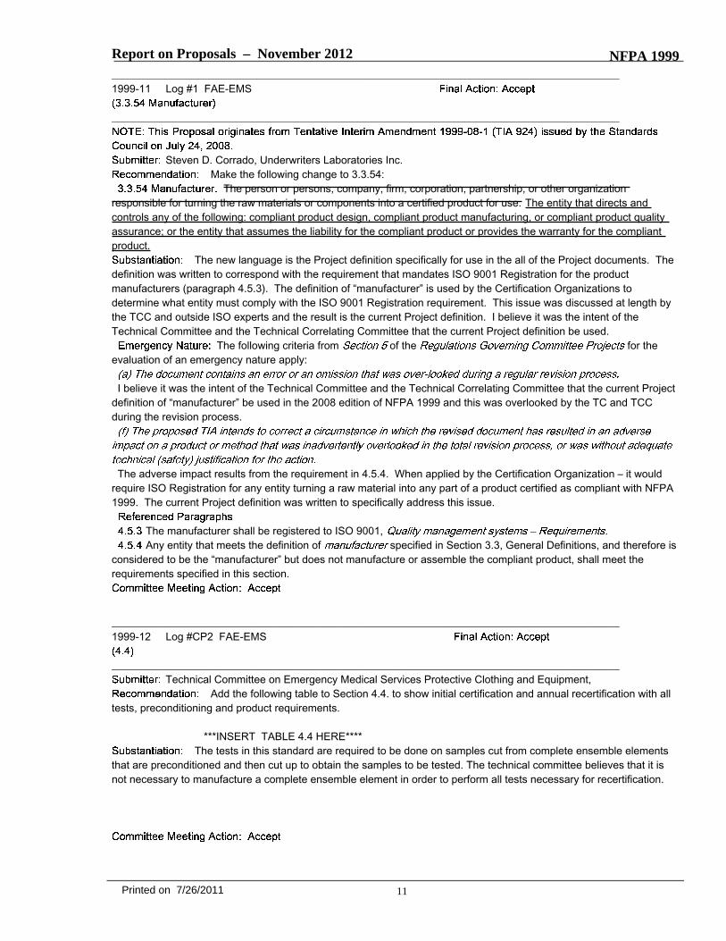
Report on Proposals – November 2012 NFPA 1999_______________________________________________________________________________________________1999-11 Log #1 FAE-EMS
_______________________________________________________________________________________________
Steven D. Corrado, Underwriters Laboratories Inc.Make the following change to 3.3.54:
The person or persons, company, firm, corporation, partnership, or other organizationresponsible for turning the raw materials or components into a certified product for use. The entity that directs andcontrols any of the following: compliant product design, compliant product manufacturing, or compliant product qualityassurance; or the entity that assumes the liability for the compliant product or provides the warranty for the compliantproduct.
The new language is the Project definition specifically for use in the all of the Project documents. Thedefinition was written to correspond with the requirement that mandates ISO 9001 Registration for the productmanufacturers (paragraph 4.5.3). The definition of “manufacturer” is used by the Certification Organizations todetermine what entity must comply with the ISO 9001 Registration requirement. This issue was discussed at length bythe TCC and outside ISO experts and the result is the current Project definition. I believe it was the intent of theTechnical Committee and the Technical Correlating Committee that the current Project definition be used.
The following criteria from of the for theevaluation of an emergency nature apply:
I believe it was the intent of the Technical Committee and the Technical Correlating Committee that the current Projectdefinition of “manufacturer” be used in the 2008 edition of NFPA 1999 and this was overlooked by the TC and TCCduring the revision process.
The adverse impact results from the requirement in 4.5.4. When applied by the Certification Organization – it wouldrequire ISO Registration for any entity turning a raw material into any part of a product certified as compliant with NFPA1999. The current Project definition was written to specifically address this issue.
The manufacturer shall be registered to ISO 9001, .Any entity that meets the definition of specified in Section 3.3, General Definitions, and therefore is
considered to be the “manufacturer” but does not manufacture or assemble the compliant product, shall meet therequirements specified in this section.
_______________________________________________________________________________________________1999-12 Log #CP2 FAE-EMS
_______________________________________________________________________________________________Technical Committee on Emergency Medical Services Protective Clothing and Equipment,
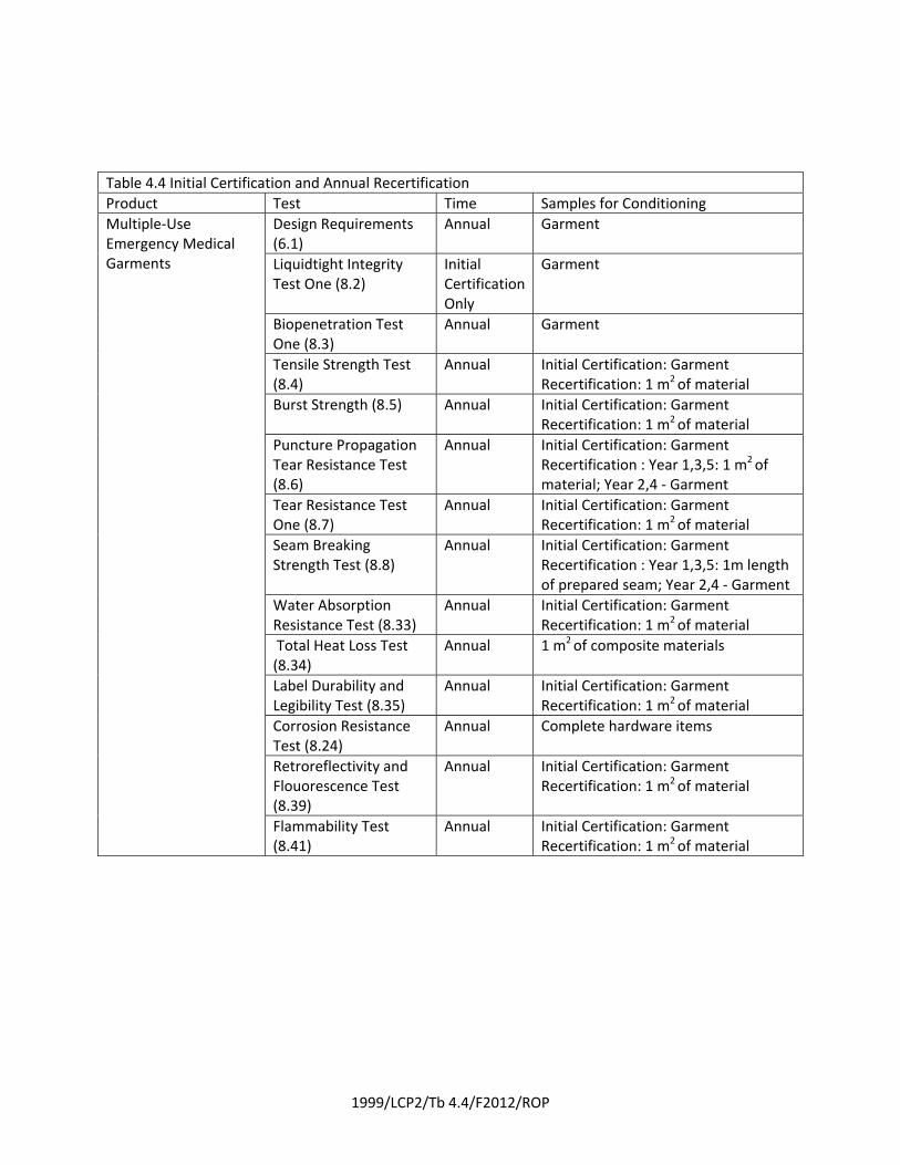
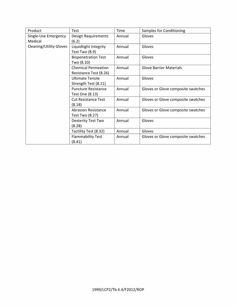
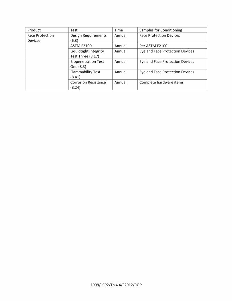
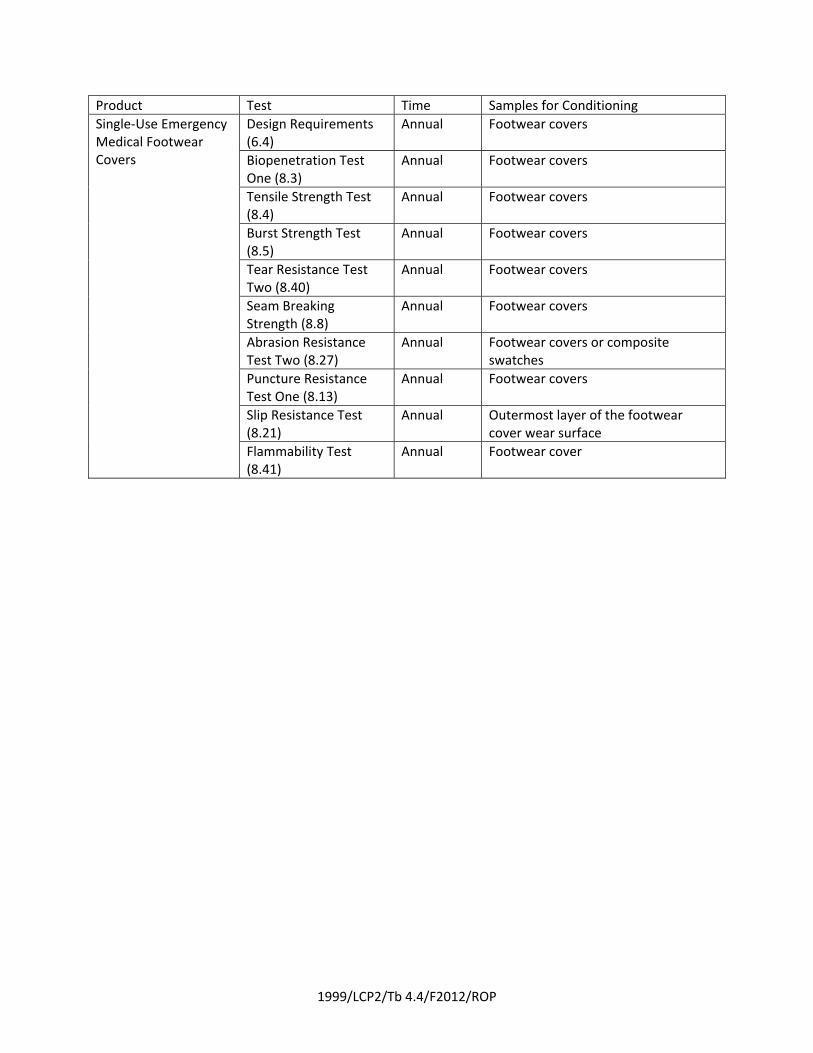
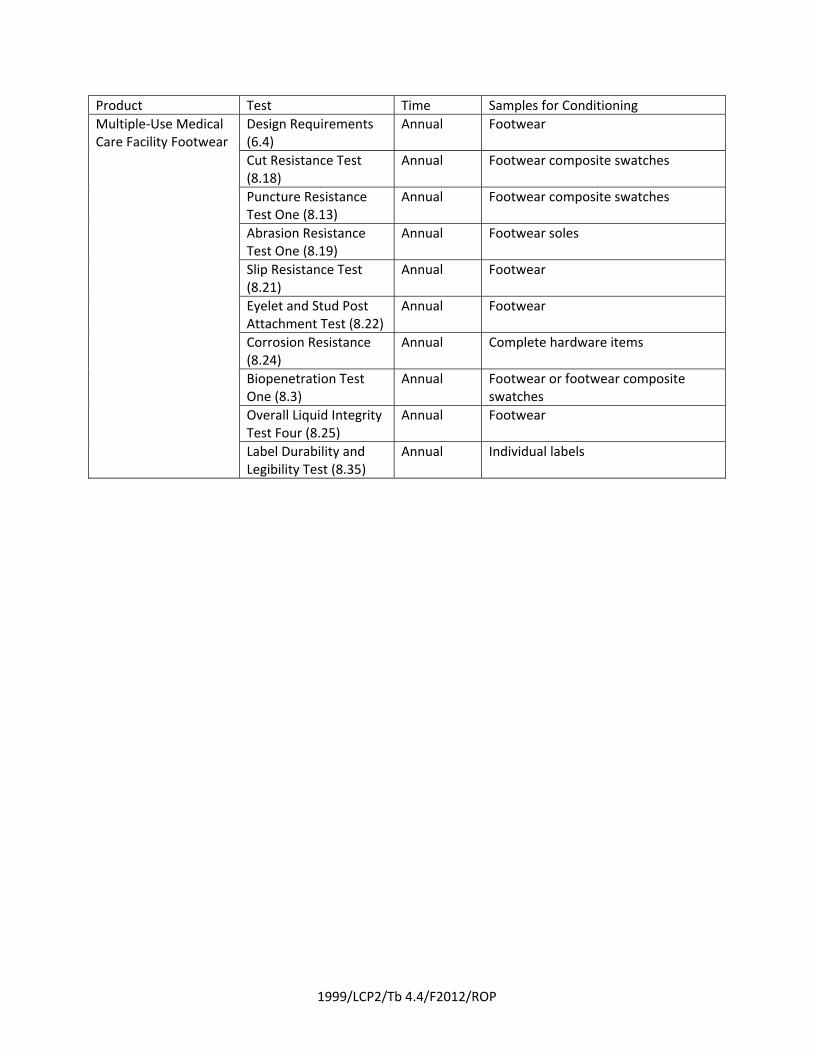
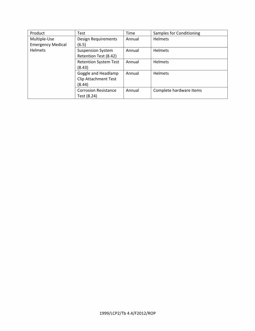
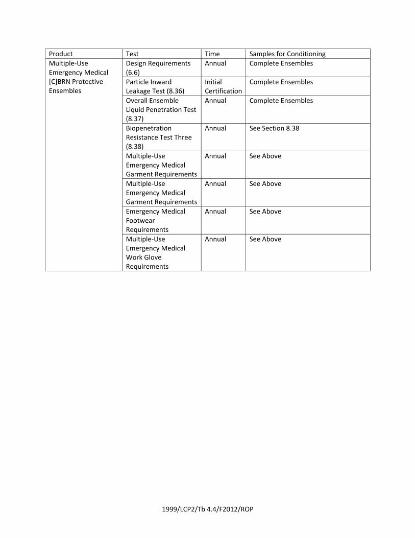
Add the following table to Section 4.4. to show initial certification and annual recertification with alltests, preconditioning and product requirements.
***INSERT TABLE 4.4 HERE****The tests in this standard are required to be done on samples cut from complete ensemble elements
that are preconditioned and then cut up to obtain the samples to be tested. The technical committee believes that it isnot necessary to manufacture a complete ensemble element in order to perform all tests necessary for recertification.
11Printed on 7/26/2011
1999/LCP2/Tb 4.4/F2012/ROP
Table 4.4 Initial Certification and Annual Recertification
Product Test Time Samples for Conditioning
Multiple‐Use Emergency Medical Garments
Design Requirements (6.1)
Annual Garment
Liquidtight Integrity Test One (8.2)
Initial Certification Only
Garment
Biopenetration Test One (8.3)
Annual Garment
Tensile Strength Test (8.4)
Annual Initial Certification: Garment Recertification: 1 m2 of material
Burst Strength (8.5) Annual Initial Certification: Garment Recertification: 1 m2 of material
Puncture Propagation Tear Resistance Test (8.6)
Annual Initial Certification: Garment Recertification : Year 1,3,5: 1 m2 of material; Year 2,4 ‐ Garment
Tear Resistance Test One (8.7)
Annual Initial Certification: Garment Recertification: 1 m2 of material
Seam Breaking Strength Test (8.8)
Annual Initial Certification: Garment Recertification : Year 1,3,5: 1m length of prepared seam; Year 2,4 ‐ Garment
Water Absorption Resistance Test (8.33)
Annual Initial Certification: Garment Recertification: 1 m2 of material
Total Heat Loss Test (8.34)
Annual 1 m2 of composite materials
Label Durability and Legibility Test (8.35)
Annual Initial Certification: Garment Recertification: 1 m2 of material
Corrosion Resistance Test (8.24)
Annual Complete hardware items
Retroreflectivity and Flouorescence Test (8.39)
Annual Initial Certification: Garment Recertification: 1 m2 of material
Flammability Test (8.41)
Annual Initial Certification: Garment Recertification: 1 m2 of material
1999/LCP2/Tb 4.4/F2012/ROP
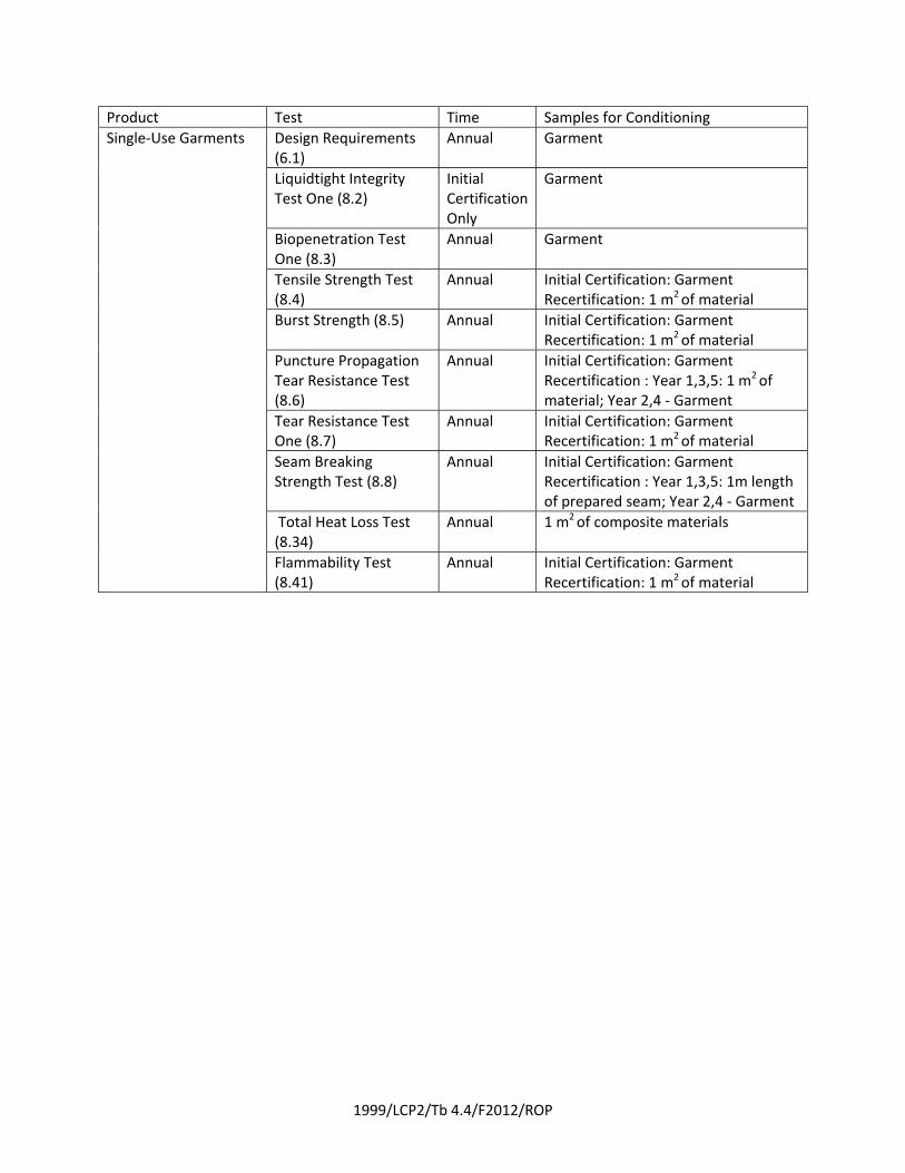
Product Test Time Samples for Conditioning
Single‐Use Garments Design Requirements (6.1)
Annual Garment
Liquidtight Integrity Test One (8.2)
Initial Certification Only
Garment
Biopenetration Test One (8.3)
Annual Garment
Tensile Strength Test (8.4)
Annual Initial Certification: Garment Recertification: 1 m2 of material
Burst Strength (8.5) Annual Initial Certification: Garment Recertification: 1 m2 of material
Puncture Propagation Tear Resistance Test (8.6)
Annual Initial Certification: Garment Recertification : Year 1,3,5: 1 m2 of material; Year 2,4 ‐ Garment
Tear Resistance Test One (8.7)
Annual Initial Certification: Garment Recertification: 1 m2 of material
Seam Breaking Strength Test (8.8)
Annual Initial Certification: Garment Recertification : Year 1,3,5: 1m length of prepared seam; Year 2,4 ‐ Garment
Total Heat Loss Test (8.34)
Annual 1 m2 of composite materials
Flammability Test (8.41)
Annual Initial Certification: Garment Recertification: 1 m2 of material
1999/LCP2/Tb 4.4/F2012/ROP
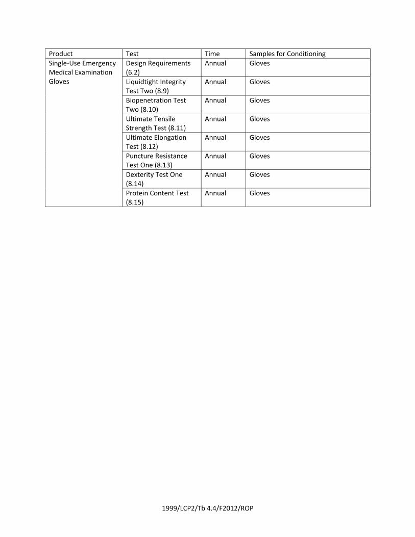
Product Test Time Samples for Conditioning
Single‐Use Emergency Medical Examination Gloves
Design Requirements (6.2)
Annual Gloves
Liquidtight Integrity Test Two (8.9)
Annual Gloves
Biopenetration Test Two (8.10)
Annual Gloves
Ultimate Tensile Strength Test (8.11)
Annual Gloves
Ultimate Elongation Test (8.12)
Annual Gloves
Puncture Resistance Test One (8.13)
Annual Gloves
Dexterity Test One (8.14)
Annual Gloves
Protein Content Test (8.15)
Annual Gloves
1999/LCP2/Tb 4.4/F2012/ROP
Product Test Time Samples for Conditioning
Single‐Use Emergency Medical Cleaning/Utility Gloves
Design Requirements (6.2)
Annual Gloves
Liquidtight Integrity Test Two (8.9)
Annual Gloves
Biopenetration Test Two (8.10)
Annual Gloves
Chemical Permeation Resistance Test (8.26)
Annual Glove Barrier Materials
Ultimate Tensile Strength Test (8.11)
Annual Gloves
Puncture Resistance Test One (8.13)
Annual Gloves or Glove composite swatches
Cut Resistance Test (8.18)
Annual Gloves or Glove composite swatches
Abrasion Resistance Test Two (8.27)
Annual Gloves or Glove composite swatches
Dexterity Test Two (8.28)
Annual Gloves
Tactility Test (8.32) Annual Gloves
Flammability Test (8.41)
Annual Gloves or Glove composite swatches
1999/LCP2/Tb 4.4/F2012/ROP
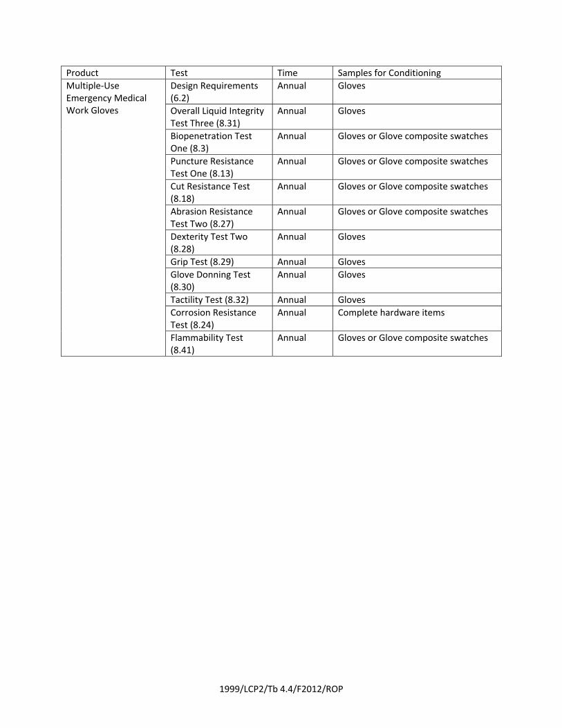
Product Test Time Samples for Conditioning
Multiple‐Use Emergency Medical Work Gloves
Design Requirements (6.2)
Annual Gloves
Overall Liquid Integrity Test Three (8.31)
Annual Gloves
Biopenetration Test One (8.3)
Annual Gloves or Glove composite swatches
Puncture Resistance Test One (8.13)
Annual Gloves or Glove composite swatches
Cut Resistance Test (8.18)
Annual Gloves or Glove composite swatches
Abrasion Resistance Test Two (8.27)
Annual Gloves or Glove composite swatches
Dexterity Test Two (8.28)
Annual Gloves
Grip Test (8.29) Annual Gloves
Glove Donning Test (8.30)
Annual Gloves
Tactility Test (8.32) Annual Gloves
Corrosion Resistance Test (8.24)
Annual Complete hardware items
Flammability Test (8.41)
Annual Gloves or Glove composite swatches

1999/LCP2/Tb 4.4/F2012/ROP
Product Test Time Samples for Conditioning
Single‐Use Emergency Medical Facemask s
Design Requirements (6.3)
Annual Facemasks
ASTM F2100 Annual Per ASTM F2100
Liquidtight Integrity Test Three (8.17)
Annual Facemasks
Visual Acuity / Fogging Resistance (8.16)
Annual Facemasks
1999/LCP2/Tb 4.4/F2012/ROP
Product Test Time Samples for Conditioning
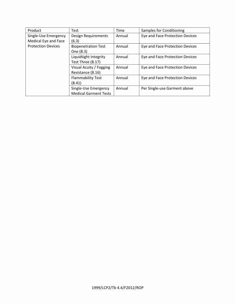
Single‐Use Emergency Medical Eye and Face Protection Devices
Design Requirements (6.3)
Annual Eye and Face Protection Devices
Biopenetration Test One (8.3)
Annual Eye and Face Protection Devices
Liquidtight Integrity Test Three (8.17)
Annual Eye and Face Protection Devices
Visual Acuity / Fogging Resistance (8.16)
Annual Eye and Face Protection Devices
Flammability Test (8.41)
Annual Eye and Face Protection Devices
Single‐Use Emergency Medical Garment Tests
Annual Per Single‐use Garment above
1999/LCP2/Tb 4.4/F2012/ROP
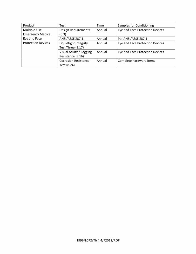
Product Test Time Samples for Conditioning
Multiple‐Use Emergency Medical Eye and Face Protection Devices
Design Requirements (6.3)
Annual Eye and Face Protection Devices
ANSI/ASSE Z87.1 Annual Per ANSI/ASSE Z87.1
Liquidtight Integrity Test Three (8.17)
Annual Eye and Face Protection Devices
Visual Acuity / Fogging Resistance (8.16)
Annual Eye and Face Protection Devices
Corrosion Resistance Test (8.24)
Annual Complete hardware items
1999/LCP2/Tb 4.4/F2012/ROP
Product Test Time Samples for Conditioning
Face Protection Devices
Design Requirements (6.3)
Annual Face Protection Devices
ASTM F2100 Annual Per ASTM F2100
Liquidtight Integrity Test Three (8.17)
Annual Eye and Face Protection Devices
Biopenetration Test One (8.3)
Annual Eye and Face Protection Devices
Flammability Test (8.41)
Annual Eye and Face Protection Devices
Corrosion Resistance (8.24)
Annual Complete hardware items
1999/LCP2/Tb 4.4/F2012/ROP
Product Test Time Samples for Conditioning
Single‐Use Emergency Medical Footwear Covers
Design Requirements (6.4)
Annual Footwear covers
Biopenetration Test One (8.3)
Annual Footwear covers
Tensile Strength Test (8.4)
Annual Footwear covers
Burst Strength Test (8.5)
Annual Footwear covers
Tear Resistance Test Two (8.40)
Annual Footwear covers
Seam Breaking Strength (8.8)
Annual Footwear covers
Abrasion Resistance Test Two (8.27)
Annual Footwear covers or composite swatches
Puncture Resistance Test One (8.13)
Annual Footwear covers
Slip Resistance Test (8.21)
Annual Outermost layer of the footwear cover wear surface
Flammability Test (8.41)
Annual Footwear cover

1999/LCP2/Tb 4.4/F2012/ROP
Product Test Time Samples for Conditioning
Multiple‐Use Emergency Medical Footwear
Design Requirements (6.4)
Annual Footwear
Cut Resistance Test (8.18)
Annual Footwear composite swatches
Puncture Resistance Test One (8.13)
Annual Footwear composite swatches
Abrasion Resistance Test One (8.19)
Annual Footwear soles
Puncture Resistance Test Two (8.20)
Annual Footwear soles
Slip Resistance Test (8.21)
Annual Footwear
Eyelet and Stud Post Attachment Test (8.22)
Annual Footwear
Impact and Compression Resistance Tests
Annual Per ASTM F2413
Corrosion Resistance (8.24)
Annual Complete hardware items
Biopenetration Test One (8.3)
Annual Footwear or footwear composite swatches
Overall Liquid Integrity Test Four (8.25)
Annual Footwear
Label Durability and Legibility Test (8.35)
Annual Individual labels
Flammability Test (8.41)
Annual Footwear or footwear composite swatches
1999/LCP2/Tb 4.4/F2012/ROP
Product Test Time Samples for Conditioning
Multiple‐Use Medical Care Facility Footwear
Design Requirements (6.4)
Annual Footwear
Cut Resistance Test (8.18)
Annual Footwear composite swatches
Puncture Resistance Test One (8.13)
Annual Footwear composite swatches
Abrasion Resistance Test One (8.19)
Annual Footwear soles
Slip Resistance Test (8.21)
Annual Footwear
Eyelet and Stud Post Attachment Test (8.22)
Annual Footwear
Corrosion Resistance (8.24)
Annual Complete hardware items
Biopenetration Test One (8.3)
Annual Footwear or footwear composite swatches
Overall Liquid Integrity Test Four (8.25)
Annual Footwear
Label Durability and Legibility Test (8.35)
Annual Individual labels
1999/LCP2/Tb 4.4/F2012/ROP
Product Test Time Samples for Conditioning
Multiple‐Use Emergency Medical Helmets
Design Requirements (6.5)
Annual Helmets
Suspension System Retention Test (8.42)
Annual Helmets
Retention System Test (8.43)
Annual Helmets
Goggle and Headlamp Clip Attachment Test (8.44)
Annual Helmets
Corrosion Resistance Test (8.24)
Annual Complete hardware items
1999/LCP2/Tb 4.4/F2012/ROP
Product Test Time Samples for Conditioning
Multiple‐Use Emergency Medical [C]BRN Protective Ensembles
Design Requirements (6.6)
Annual Complete Ensembles
Particle Inward Leakage Test (8.36)
Initial Certification
Complete Ensembles
Overall Ensemble Liquid Penetration Test (8.37)
Annual Complete Ensembles
Biopenetration Resistance Test Three (8.38)
Annual See Section 8.38
Multiple‐Use Emergency Medical Garment Requirements
Annual See Above
Multiple‐Use Emergency Medical Garment Requirements
Annual See Above
Emergency Medical Footwear Requirements
Annual See Above
Multiple‐Use Emergency Medical Work Glove Requirements
Annual See Above
Report on Proposals – November 2012 NFPA 1999_______________________________________________________________________________________________1999-13 Log #CP15 FAE-EMS
_______________________________________________________________________________________________Technical Committee on Emergency Medical Services Protective Clothing and Equipment,
Delete the following design requirement:Snaps shall be Style 2 and shall comply with the design and construction requirements of MIL-F-10884G,
. The construction of the snap shall be permitted to vary from the MIL-F-10884G drawings with regardto the attachment means and the use of logos on the caps.
This change is proposed for harmonization with other standards in the project; the applicationperformance requirement for snaps is corrosion resistance and functionality following corrosion resistance.
12Printed on 7/26/2011
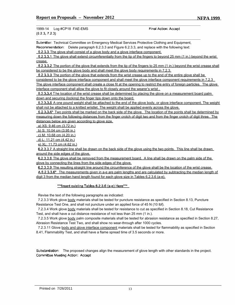
Report on Proposals – November 2012 NFPA 1999_______________________________________________________________________________________________1999-14 Log #CP18 FAE-EMS
_______________________________________________________________________________________________Technical Committee on Emergency Medical Services Protective Clothing and Equipment,
Delete paragraph 6.2.3.3 and Figure 6.2.3.3, and replace with the following text:The glove shall consist of a glove body and a glove interface component.
The glove shall extend circumferentially from the tip of the fingers to beyond 25 mm (1 in.) beyond the wristcrease.
The portion of the glove that extends from the tip of the fingers to 25 mm (1 in.) beyond the wrist crease shallbe considered to be the glove body and shall meet the glove body requirements in 7.2.3.
The portion of the glove that extends from the wrist crease up to the end of the entire glove shall beconsidered to be the glove interface component and shall meet the glove interface component requirements in 7.2.3The glove interface component shall create a close fit at the opening to restrict the entry of foreign particles. The gloveinterface component shall allow the glove to fit closely around the wearer’s wrist .
he location of the wrist crease shall be determined by placing the glove on a measurement board palmdown and securing (locking) the finger tips down onto the board.
A one pound weight shall be attached to the end of the glove body, or glove interface component. The weightshall not be attached to a knitted wristlet. The weight shall be applied evenly across the glove.
Two points shall be marked on the back side of the glove. The location of the points shall be determined bymeasuring down the following distances from the finger crotch of digit two and from the finger crotch of digit three. Thedistances below are given according to glove size.a) XS: 9.46 cm (3.72 in.)b) S: 10.04 cm (3.95 in.)c) M: 10.68 cm (4.20 in.)d) L: 11.21 cm (4.42 in.)e) XL: 11.73 cm (4.62 in.)
A straight line shall be drawn on the back side of the glove using the two points. This line shall be drawnaround the side edges of the glove.
The glove shall be removed from the measurement board. A line shall be drawn on the palm side of theglove by connecting the lines from the side edges of the glove.
The resulting straight line around the circumference of the glove shall be the location of the wrist crease.The measurements given in a-e are palm lengths and are calculated by subtracting the median length of
digit 3 from the median hand length found for each glove size in Tables 6.2.3.6 (a-e).
Revise the text of the following paragraphs as indicated:7.2.3.3 Work glove body materials shall be tested for puncture resistance as specified in Section 8.13, Puncture
Resistance Test One, and shall not puncture under an applied force of 45 N (10 lbf).7.2.3.4 Work glove body materials shall be tested for resistance to cut as specified in Section 8.18, Cut Resistance
Test, and shall have a cut distance resistance of not less than 25 mm (1 in.).7.2.3.5 Work glove body palm composite materials shall be tested for abrasion resistance as specified in Section 8.27,
Abrasion Resistance Test Two, and shall show no wear-through after 1000 cycles.7.2.3.11 Glove body and glove interface component materials shall be tested for flammability as specified in Section
8.41, Flammability Test, and shall have a flame spread time of 3.5 seconds or more.
The proposed changes align the measurement of glove length with other standards in the project.
13Printed on 7/26/2011

1999/LCP18/Tb 6.2.3.6(a)/F2012/ROP
Table 6.2.3.6(a) Sizing for Extra-Small (XS) Glove
mm in.
Range for hand length:
16.25–17.25 6.40–6.79
Range for hand circumference:
16.25–20.25 6.40–7.97
Mid-Size Value Range to Be Accommodated
cm in. cm in.
Digit 1 circumference
6.17 2.43 5.60–6.74 2.20–2.65
Digit 2 circumference
6.06 2.39 5.50–6.63 2.17–2.61
Digit 3 circumference
6.08 2.39 5.53–6.63 2.18–2.61
Digit 4 circumference
5.69 2.24 5.12–6.26 2.02–2.46
Digit 5 circumference
5.00 1.97 4.48–5.52 1.76–2.17
Digit 1 length 4.94 1.94 4.36–5.52 1.72–2.17
Digit 2 length 6.44 2.54 5.75–7.12 2.26–2.80
Digit 3 length 7.29 2.87 6.71–7.87 2.64–3.10
Digit 4 length 6.78 2.67 6.13–7.42 2.41–2.92
Digit 5 length 5.09 2.00 4.52–5.66 1.78–2.23
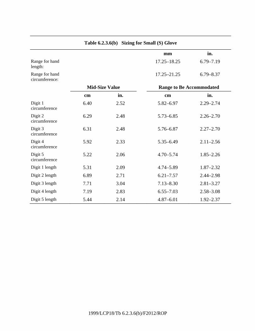
1999/LCP18/Tb 6.2.3.6(b)/F2012/ROP
Table 6.2.3.6(b) Sizing for Small (S) Glove
mm in.
Range for hand length:
17.25–18.25 6.79–7.19
Range for hand circumference:
17.25–21.25 6.79–8.37
Mid-Size Value Range to Be Accommodated
cm in. cm in.
Digit 1 circumference
6.40 2.52 5.82–6.97 2.29–2.74
Digit 2 circumference
6.29 2.48 5.73–6.85 2.26–2.70
Digit 3 circumference
6.31 2.48 5.76–6.87 2.27–2.70
Digit 4 circumference
5.92 2.33 5.35–6.49 2.11–2.56
Digit 5 circumference
5.22 2.06 4.70–5.74 1.85–2.26
Digit 1 length 5.31 2.09 4.74–5.89 1.87–2.32
Digit 2 length 6.89 2.71 6.21–7.57 2.44–2.98
Digit 3 length 7.71 3.04 7.13–8.30 2.81–3.27
Digit 4 length 7.19 2.83 6.55–7.03 2.58–3.08
Digit 5 length 5.44 2.14 4.87–6.01 1.92–2.37
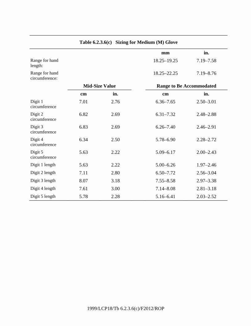
1999/LCP18/Tb 6.2.3.6(c)/F2012/ROP
Table 6.2.3.6(c) Sizing for Medium (M) Glove
mm in.
Range for hand length:
18.25–19.25 7.19–7.58
Range for hand circumference:
18.25–22.25 7.19–8.76
Mid-Size Value Range to Be Accommodated
cm in. cm in.
Digit 1 circumference
7.01 2.76 6.36–7.65 2.50–3.01
Digit 2 circumference
6.82 2.69 6.31–7.32 2.48–2.88
Digit 3 circumference
6.83 2.69 6.26–7.40 2.46–2.91
Digit 4 circumference
6.34 2.50 5.78–6.90 2.28–2.72
Digit 5 circumference
5.63 2.22 5.09–6.17 2.00–2.43
Digit 1 length 5.63 2.22 5.00–6.26 1.97–2.46
Digit 2 length 7.11 2.80 6.50–7.72 2.56–3.04
Digit 3 length 8.07 3.18 7.55–8.58 2.97–3.38
Digit 4 length 7.61 3.00 7.14–8.08 2.81–3.18
Digit 5 length 5.78 2.28 5.16–6.41 2.03–2.52
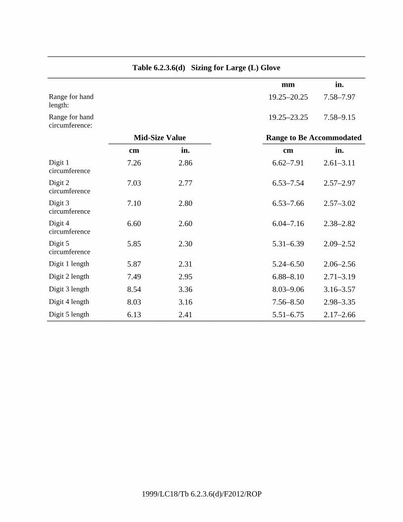
1999/LC18/Tb 6.2.3.6(d)/F2012/ROP
Table 6.2.3.6(d) Sizing for Large (L) Glove
mm in.
Range for hand length:
19.25–20.25 7.58–7.97
Range for hand circumference:
19.25–23.25 7.58–9.15
Mid-Size Value Range to Be Accommodated
cm in. cm in.
Digit 1 circumference
7.26 2.86 6.62–7.91 2.61–3.11
Digit 2 circumference
7.03 2.77 6.53–7.54 2.57–2.97
Digit 3 circumference
7.10 2.80 6.53–7.66 2.57–3.02
Digit 4 circumference
6.60 2.60 6.04–7.16 2.38–2.82
Digit 5 circumference
5.85 2.30 5.31–6.39 2.09–2.52
Digit 1 length 5.87 2.31 5.24–6.50 2.06–2.56
Digit 2 length 7.49 2.95 6.88–8.10 2.71–3.19
Digit 3 length 8.54 3.36 8.03–9.06 3.16–3.57
Digit 4 length 8.03 3.16 7.56–8.50 2.98–3.35
Digit 5 length 6.13 2.41 5.51–6.75 2.17–2.66
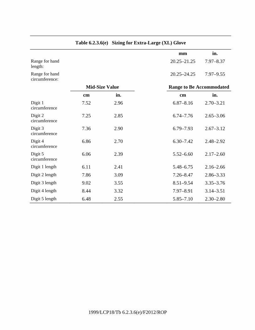
1999/LCP18/Tb 6.2.3.6(e)/F2012/ROP
Table 6.2.3.6(e) Sizing for Extra-Large (XL) Glove
mm in.
Range for hand length:
20.25–21.25 7.97–8.37
Range for hand circumference:
20.25–24.25 7.97–9.55
Mid-Size Value Range to Be Accommodated
cm in. cm in.
Digit 1 circumference
7.52 2.96 6.87–8.16 2.70–3.21
Digit 2 circumference
7.25 2.85 6.74–7.76 2.65–3.06
Digit 3 circumference
7.36 2.90 6.79–7.93 2.67–3.12
Digit 4 circumference
6.86 2.70 6.30–7.42 2.48–2.92
Digit 5 circumference
6.06 2.39 5.52–6.60 2.17–2.60
Digit 1 length 6.11 2.41 5.48–6.75 2.16–2.66
Digit 2 length 7.86 3.09 7.26–8.47 2.86–3.33
Digit 3 length 9.02 3.55 8.51–9.54 3.35–3.76
Digit 4 length 8.44 3.32 7.97–8.91 3.14–3.51
Digit 5 length 6.48 2.55 5.85–7.10 2.30–2.80
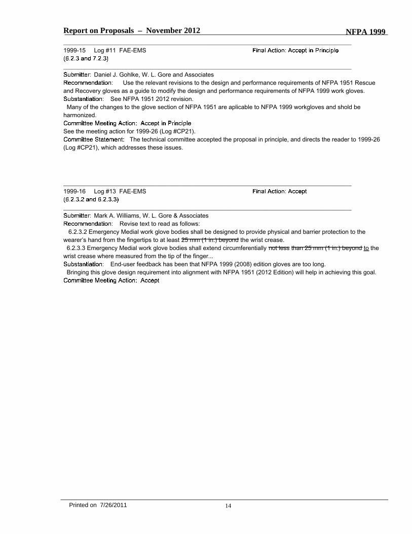
Report on Proposals – November 2012 NFPA 1999_______________________________________________________________________________________________1999-15 Log #11 FAE-EMS
_______________________________________________________________________________________________Daniel J. Gohlke, W. L. Gore and Associates
Use the relevant revisions to the design and performance requirements of NFPA 1951 Rescueand Recovery gloves as a guide to modify the design and performance requirements of NFPA 1999 work gloves.
See NFPA 1951 2012 revision.Many of the changes to the glove section of NFPA 1951 are aplicable to NFPA 1999 workgloves and shold be
harmonized.
See the meeting action for 1999-26 (Log #CP21).The technical committee accepted the proposal in principle, and directs the reader to 1999-26
(Log #CP21), which addresses these issues.
_______________________________________________________________________________________________1999-16 Log #13 FAE-EMS
_______________________________________________________________________________________________Mark A. Williams, W. L. Gore & Associates
Revise text to read as follows:6.2.3.2 Emergency Medial work glove bodies shall be designed to provide physical and barrier protection to the
wearer’s hand from the fingertips to at least 25 mm (1 in.) beyond the wrist crease.6.2.3.3 Emergency Medial work glove bodies shall extend circumferentially not less than 25 mm (1 in.) beyond to the
wrist crease where measured from the tip of the finger...End-user feedback has been that NFPA 1999 (2008) edition gloves are too long.
Bringing this glove design requirement into alignment with NFPA 1951 (2012 Edition) will help in achieving this goal.
14Printed on 7/26/2011
Report on Proposals – November 2012 NFPA 1999_______________________________________________________________________________________________1999-17 Log #CP16 FAE-EMS
_______________________________________________________________________________________________Technical Committee on Emergency Medical Services Protective Clothing and Equipment,
Revise the design requirement as follows:Where the eye and face protection device is configured as safety glasses, the safety glasses shall meet the
design respective requirements for Spectacles in Section 7 of and be marked “Z87+” in accordance with ANSI/ASSEZ87.1, including basic impact.
Where the eye and face protection device is configured as goggles, the goggles shall meet the designrespective requirements for Goggles in Section 8 of and be marked “Z87+” in accordance with ANSI/ASSE Z87.1,
including basic impact.Where the eye and face protection device is configured as a faceshield, the faceshield shall meet the design
respective requirements for Faceshields in Section 9 of and be marked “Z87+” in accordance with ANSI/ASSE Z87.1,including basic impact.
Delete the following performance requirements:Eye and face protection devices that are spectacle or eye and face protection devices that incorporate designs
similar to spectacles shall meet the requirements for spectacles in accordance with Section 7 of ANSI/ASSE Z87.1,including requirements for basic impact
resistance.7.3.3.2 Eye and face protection devices that are goggles or eye and face protection devices that incorporate designs
similar to goggles shall meet the requirements for goggles in accordance with Section 8 of ANSI/ASSE Z87.1,including requirements for basic impact
resistance.7.3.3.3 Eye and face protective devices that are faceshields or eye and face protection devices that incorporate
designs similar to faceshields shall meet the requirements for faceshields in accordance with Section 9 of ANSI/ASSEZ87.1, , including requirements for basicimpact resistance.
The edition of ANSI Z87.1 (eyewear standard) has been updated changes are needed to address thenew reference align the ANSI Z87.1 requirements and language for protective eyewear in other standards in the project.
_______________________________________________________________________________________________1999-18 Log #12 FAE-EMS
_______________________________________________________________________________________________Daniel J. Gohlke, W. L. Gore and Associates
Use the relevant revisions to the design and performance requirements of NFPA 1951 Rescue andRecovery Footwear as a guide to modify the design and performance requirements of NFPA 1999 Multiple UseFootwear.
See NFPA 1951 2012 Revision.Many of these changes to the footwear section of NFPA 1951 are applicable to NFPA 1999 multiple use footwear and
should be harmonized.
See the meeting action for 1999-26 (Log #CP21).The technical committee accepted the proposal in principle, and directs the reader to 1999-26
(Log #CP21), which addresses these issues.
15Printed on 7/26/2011
Report on Proposals – November 2012 NFPA 1999_______________________________________________________________________________________________1999-19 Log #CP14 FAE-EMS
_______________________________________________________________________________________________Technical Committee on Emergency Medical Services Protective Clothing and Equipment,
Delete the following design requirement:Zippers shall meet the physical performance requirements of A-A-55634,
.Add the following performance requirement:
Garment zippers shall be tested for crosswise breaking strength of chain, crosswise breaking strength ofseparating unit, holding strengths of stops, retainers and separating units, operating force, and slider lock strengthrequirements of A-A-55634A, Commercial Item Description, Zippers (Fasteners, Slide, Interlocking).
These changes are proposed for harmonization with other standards in the project for defining therequirements for zippers.
_______________________________________________________________________________________________1999-20 Log #CP7 FAE-EMS
_______________________________________________________________________________________________Technical Committee on Emergency Medical Services Protective Clothing and Equipment,
Change test paragraphs to read as follows:Cleaning/utility gloves shall be tested for resistance to cut as specified in Section 8.18, Cut Resistance Test,
and shall have a cut distance resistance of greater blade travel distance not less than 25 mm (1 in.) 20 mm (0.8 in.).Work glove materials shall be tested for resistance to cut as specified in Section 8.18, Cut Resistance Test,
and shall have a cut distance resistance of blade travel distance not less 25 mm (1 in.) 20 mm (0.8 in.).Footwear uppers shall be tested for cut resistance as specified in Section 8.18, Cut Resistance Test, and shall
have a cut distance resistance of greater blade travel distance not less than 25 mm (1 in.) 20 mm (0.8 in.).Footwear uppers shall be tested for cut resistance as specified in Section 8.18, Cut Resistance Test, and shall
have a cut distance resistance of greater blade travel distance not less than 25 mm (1 in.) 20 mm (0.8 in.).Change test method paragraphs to read as follows:
Cut resistance testing shall be performed under a load of 50 g (1.8 oz) 25 g (0.9 oz).Cut resistance testing shall be performed under a load of 200 g (7 oz) 150 g (5.3 oz).Cut resistance testing shall be performed under a load of 400 g (14 oz) 350 g (12.3 oz).
Cut resistance testing shall be performed under a load of 200 grams (7 oz) 150 grams (5.3 oz).
The test method for cut resistance is not consistent with the reference for performing cut resistancetesting. Changes in the criteria based on a different blade travel distance accordingly requires a downward change inthe test load as was done in NFPA 1971, NFPA 1991, and NFPA 1994.
16Printed on 7/26/2011

Report on Proposals – November 2012 NFPA 1999_______________________________________________________________________________________________1999-21 Log #14 FAE-EMS
_______________________________________________________________________________________________Mark A. Williams, W. L. Gore & Associates
Revise text to read as follows:7.2.3.3 Work glove materials shall be tested for puncture resistance as specified in Section 8.13, Puncture Resistance
Test, and shall not puncture under an applied force 45 22 N. (10 5 lbf).Improving the dexterity and tactility of NFPA 1999 gloves is an important goal.
Bringing the Puncture requirement into alignment with NFPA 1951 (2012 Edition) will help in achieving this goal.
_______________________________________________________________________________________________1999-22 Log #15 FAE-EMS
_______________________________________________________________________________________________Mark A. Williams, W. L. Gore & Associates
Revise text to read as follows:7.2.3.4 Work glove materials shall be tested for resistance to cut as specified in Section 8.18, Cut Resistance Test, and
shall have a cut distance of not less than 25 20 mm. (1 0.8 in.).Improving the dexterity and tactility of NFPA 1999 gloves is an important goal.
Bringing the Cut requirement into alignment with NFPA 1951 (2012 Edition) will help in achieving this goal.Note that the ASTM cut test changed a few years ago and this modification was necessary to offset those changes.
_______________________________________________________________________________________________1999-23 Log #17 FAE-EMS
_______________________________________________________________________________________________Mark A. Williams, W. L. Gore & Associates
Revise text to read as follows:7.2.3.6 Gloves shall be tested for hand function as specified in Section 8.28, Dexterity Test Two, and shall not have an
average percent of barehand control exceeding 200 170 percent.
****Insert Include 1999_L17_S Here****
17Printed on 7/26/2011
1 NFPA 1999 L17 Sub F2012 ROP
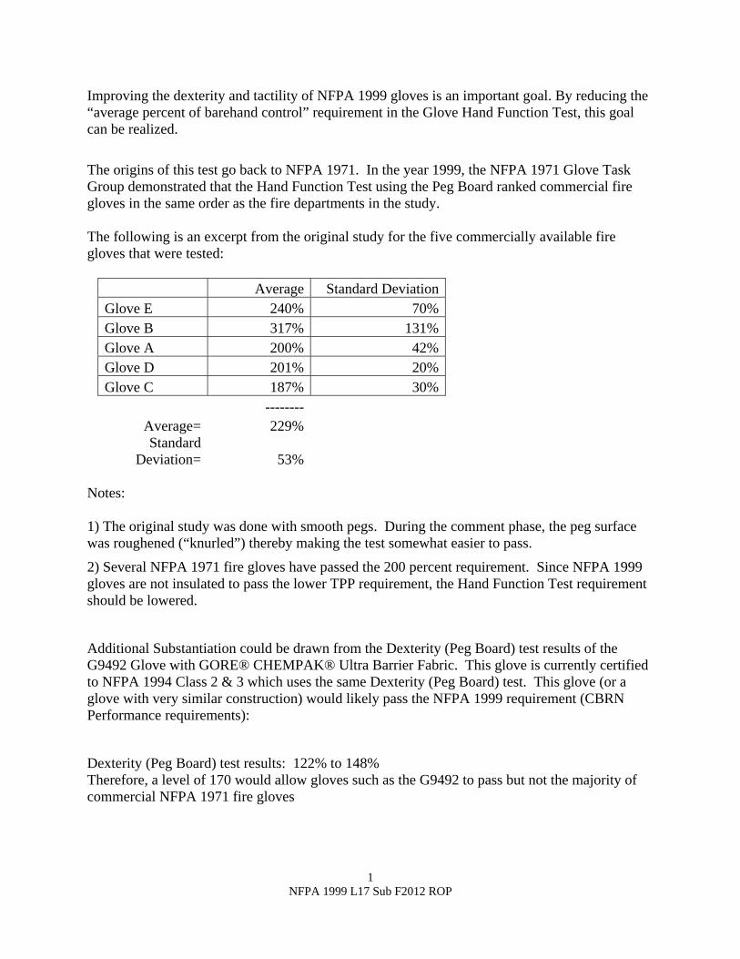
Improving the dexterity and tactility of NFPA 1999 gloves is an important goal. By reducing the “average percent of barehand control” requirement in the Glove Hand Function Test, this goal can be realized.
The origins of this test go back to NFPA 1971. In the year 1999, the NFPA 1971 Glove Task Group demonstrated that the Hand Function Test using the Peg Board ranked commercial fire gloves in the same order as the fire departments in the study. The following is an excerpt from the original study for the five commercially available fire gloves that were tested:
Average Standard DeviationGlove E 240% 70%Glove B 317% 131%Glove A 200% 42%Glove D 201% 20%Glove C 187% 30% --------
Average= 229% Standard
Deviation= 53% Notes: 1) The original study was done with smooth pegs. During the comment phase, the peg surface was roughened (“knurled”) thereby making the test somewhat easier to pass.
2) Several NFPA 1971 fire gloves have passed the 200 percent requirement. Since NFPA 1999 gloves are not insulated to pass the lower TPP requirement, the Hand Function Test requirement should be lowered.
Additional Substantiation could be drawn from the Dexterity (Peg Board) test results of the G9492 Glove with GORE® CHEMPAK® Ultra Barrier Fabric. This glove is currently certified to NFPA 1994 Class 2 & 3 which uses the same Dexterity (Peg Board) test. This glove (or a glove with very similar construction) would likely pass the NFPA 1999 requirement (CBRN Performance requirements):
Dexterity (Peg Board) test results: 122% to 148% Therefore, a level of 170 would allow gloves such as the G9492 to pass but not the majority of commercial NFPA 1971 fire gloves
Report on Proposals – November 2012 NFPA 1999_______________________________________________________________________________________________1999-24 Log #CP19 FAE-EMS
_______________________________________________________________________________________________Technical Committee on Emergency Medical Services Protective Clothing and Equipment,
Revise text to read as follows:Work gloves shall be tested for grip as specified in Section 8.29, Grip Test, and shall have a weight pulling
capacity not less than 80 percent of the barehand control values not have a drop of more than 30 percent from the peakpull force value.Delete 8.29, and replace with the following:
This test method shall apply to work gloves.
A minimum of three glove pairs each for small and large sizes shall be used for testing.Each glove pair shall be tested as a complete set of gloves in new, as-distributed, condition.Glove pair specimens shall not receive special softening treatments prior to tests.Glove pair specimens shall be tested for each material and construction combination.
Glove pair specimens shall be preconditioned as specified in 8.1.9 8.1.2.Glove pair specimens shall be tested after being conditioned for dry conditions as specified in 8.1.2.
The pulling device shall be a 1 1/4 in. diameter fiberglass pole attached to an overheadcalibrated force measuring device in such a fashion that pulls on the pole will be perpendicular to the ground anddownward in direction. This pole shall be used until surface degradation occurs.
Test subjects shall be selected so that their hand dimensions are as close as possible to the middle of therange for hand length and hand circumference as specified in the tables provided for size small and size large gloves inSection 6.2.2.6. At least three test subjects shall be selected for both size small and size large.
The gloves shall be conditioned by the wetting procedure specified in 8.1.8 before each set of three pulls bythe test subject as described below.
The pulling device shall be wet conditioned before each individual pull by wiping with a damp rag.The test subject shall then make three pulls on the pulling device with gloves with peak and minimum pull
force values measured. Pulls shall be performed as described below:(1) The test subject shall stand with feet together, firmly planted on the ground, and knees slightly bent.(2) The stand shall be adjusted such that the cushioned bar is touching the test subject's chest. The stand shall prevent
the test subject’s forward movement during the pull.(3) The test subject shall extend the arms in front of the body at shoulder height to grab the pulling device for pulling
vertically down from the ceiling.(4) The test subject shall stand in a comfortable pulling position with the arms bent at an angle of approximately 90
degrees and in any case the arms shall not be completely extended or touching the body.(5) The test subject shall grasp the pulling device with hands next to each other. Thumbs shall not overlap the fingers.(6) The test subject shall pull the rope or pole with as much pulling force as possible in a smooth, steady, swift, and
non-jerking action. The test subject shall not bend the knees further or pull down with body weight during the pull.(7) The test subject shall continuously pull on the pulling device for a minimum of 5 +1/-0 sec.(8) The test subject shall continue to pull until the test facilitator observes a peak pulling force and instructs the test
subject to end the pull.
The peak pull force value for each individual pull shall be recorded and reported.The minimum pull force value occurring after the peak pull force value shall be recorded and reported.The percentage drop between the peak pull force value and the minimum pull force value shall be calculated,
recorded, and reported.
The individual percentage drop between the peak pull force value and the minimum pull force value shall beused to determine pass or fail performance.
Failure of either size during any pull shall constitute failure of the test.
18Printed on 7/26/2011

Report on Proposals – November 2012 NFPA 1999
The committee is considering the adoption of this revised grip test method that has been implementedin other standards within the project. However, the test method must be subject to an interlaboratory precision study anda field study is needed to establish suitable performance criteria as the currently proposed criteria has beenrecommended for structural fire fighting gloves.
19Printed on 7/26/2011
Report on Proposals – November 2012 NFPA 1999_______________________________________________________________________________________________1999-25 Log #CP20 FAE-EMS
_______________________________________________________________________________________________Technical Committee on Emergency Medical Services Protective Clothing and Equipment,
Add a new paragraph to the end of Section 7.2.3 as follows:Work gloves shall be tested for grip function as specified in Section 8.X, Glove Torque Test, and shall have an
average percent of bare-handed control not less than 80 percent.Add the following new performance requirement to the end of Chapter 8:
This test method shall apply to work gloves.
A minimum of three glove specimens each for size small and size large shall be used for testing.Right-hand specimen gloves shall be used for right-hand dominant test subjects while left-hand specimen
gloves shall be used for left-hand dominant test subjects.Each glove pair shall be tested in new, as distributed, condition.Glove pair specimens shall not receive special softening treatments prior to testing.Glove pair specimens shall be tested for each material and construction combination.
Samples for conditioning shall be whole gloves.Sample glove pairs shall be preconditioned as specified in 8.1.2.
Torque testing shall be evaluated with the use of a 1 5/8 in. solid acrylic cylinder securely centeredon a calibrated digital torque meter capable of measuring up to 88.5 lb-in (10.00 N-m).
Test subjects shall be selected so that their hand dimensions are as close as possible to the middle of theranges for hand length and hand circumference as specified in the tables provided for size small and size large gloves in6.7.6.
While standing, each test subject shall grasp the cylinder so that the elbow is against the side of the body andthe arm bend creates a right angle.
For right-hand dominant test subjects, the direction mode on the torque device shall be set to “open” orcounter-clockwise and set to “close” or clockwise for left-hand dominant test subjects.
Each test subject shall make five successive attempts to twist the cylinder in the appropriate direction exertingas much force as possible. The range of motion of the subject’s arm shall indicate the end of the twisting cycle. Theaverage maximum force over the five attempts shall be the bare-handed control value.
Each test subject shall test a minimum of three sample gloves using the method specified in 8.X.5.2 to 8.X.5.4.Test subjects shall attempt one trial with each glove. A trial shall consist of five successive attempts. The averagemaximum twisting force over the five attempts shall be the twisting force with the glove. The average twisting force shallbe calculated, recorded, and reported for each glove.
The average max twisting force with gloves over the three trials for each size shall be calculated, recorded,and reported. The average twisting force shall be compared with the barehanded control value.
The percentage of bare-handed control value shall be calculated as follows:Percentage of bare-handed control value = ( PFg / CVb ) x 100where:PFg = average twisting force with gloveCVb = bare-handed control value
The percentage of bare-handed control value shall be recorded and reported for each specimen glovesize.
The percentage of bare-handed control value for size small and size large shall be used to determine pass orfail performance.
Failure of either size shall constitute failure of the test.
The committee is considering the adoption of this new hand function test method that has beenimplemented in other standards within the project. However, the test method must be subject to an interlaboratory
20Printed on 7/26/2011

Report on Proposals – November 2012 NFPA 1999precision study and a field study is needed to establish suitable performance criteria as the currently proposed criteriahas been recommended for structural fire fighting gloves.
21Printed on 7/26/2011
Report on Proposals – November 2012 NFPA 1999_______________________________________________________________________________________________1999-26 Log #CP21 FAE-EMS
_______________________________________________________________________________________________Technical Committee on Emergency Medical Services Protective Clothing and Equipment,
Revise text in 7.2.3.8 and Chapter 8 as follows:Work gloves shall be tested for ease of donning as specified in Section 8.30, Glove Donning Test, and shall not
have a baseline donning time exceed 10 seconds, a final donning time not to exceed the baseline donning time plus20.0 seconds, shall have no detachment of the inner liner, shall have no detachment of the moisture barrier, and shallallow full insertion of all digits.
The complete garment shall be washed with all closures fastened.A front-loading washer/extractor shall be used.Two-thirds the rated capacity of the washer shall not be exceeded.The wash cycle procedure in Table 8.1.3.4 shall be followed. Water temperature shall be within ±3°C (±5°F) of
the value in the table.The garment shall be dried using a tumble dryer with a stack temperature of 38°C to 49°C (100°F to 120°F).The garment shall be tumbled for 60 minutes and shall be removed immediately at the end of the drying cycle.
At the conclusion of the final drying cycle, the garment shall be allowed to air dry for at least 48 hours prior to conductingthe test.
The garment shall be washed and dried for a total of 25 washings and 25 drying cycles.For work gloves and work glove pouches, if ballast is needed to reach two-thirds capacity 7.5 oz Nomex
ballast shall be used.Work gloves and work glove pouches shall be dried using a tumble dryer with a stack temperature of 38°C to
49°C (100°F to 120°F) when measured on an empty load 20 minutes into the drying cycle.Work gloves and work glove pouches shall be tumbled for 60 minutes and shall be removed immediately at
the end of the drying cycle. At the conclusion of the final drying cycle, the garment shall be dried on a forced airnon-tumble drying mechanism operated at 10ºC above current room temperature until completely dry.
Work gloves and work glove pouches shall be washed and dried for a total of 10 washings and 10 dryingcycles.
Specimens shall be subjected to 10 cycles of washing and drying in accordance with the procedure specified inMachine Cycle 1,Wash Temperature V, and Drying Procedure Ai, of AATCC 135,
.A 1.8 kg, ±0.1 kg (4 lb, ±0.2 lb) load shall be used. A laundry bag shall not be used.
Samples shall be conditioned by complete immersion in water at a temperature of 21°C, ±3°C (70°F, ±5°F), for2 minutes.
Samples shall be removed from water, hung in a vertical position for 5 minutes, and laid horizontal with AATCCtextile blotting paper both under and over the sample under a weight of 0.0020 kg/cm2, ±0.0002 kg/cm2 (0.50 psi, ±0.05psi), for a periodof 20 minutes in accordance with paragraph 7.2 of AATCC 70,
.Test subjects shall be selected such that their hand dimensions are as close as possible to those specified in
accordance with manufacturing glove-sizing guidelines.The wrist crease location shall be marked as described in X.X.X.X on each specimen around the entire glove
+0/-3 mm (+0/-0.25 in.). Then, in the same manner, the water height line shall also be marked on each specimen 25mm (1 in.) +0/-3 mm (+0/-0.25 in.) below (towards the fingers) the location of the wrist crease around the entire glove.
The test subject shall don the test specimen gloves.The test subject shall immerse the donned specimens straight down into two containers of water at a
temperature of 21°C, ±3°C (70°F, ±5°F) to the water height line for 15 secs +1.5/-0 sec.The glove specimens shall be tested within 1 min.
Work Glove Test Areas shall be as described below and shown in Figure 8.1.X.1. Work Glove Test Areaabbreviations shall be as follows: P=Palm; B=Back; S=Side.A-P.) Palm side of hand from finger crotch line to 1/3 of the way down (grasp area)
22Printed on 7/26/2011
Report on Proposals – November 2012 NFPA 1999B-P.) Palm side of hand from 1/3 of the way down (grasp area) to the wrist creaseC-P.) Palm side of hand from the wrist crease to 50 mm (2 in.) past the wrist creaseD-P.) Palm side of thumbE-P.) Palm side of tip of thumbF-P.) Palm side of index fingerG-P.) Palm side of fingertip of index fingerH-P.) Palm side of non-index fingersI-P.) Palm side of fingertip of non-index fingersA-PS.) Sides of hand adjacent to section A-PB-PS.) Outside of hand adjacent to section B-PC-PS.) Sides of hand adjacent to section C-PD-PS.) Outside of thumb adjacent to section D-PE-PS.) Inside of thumb adjacent to section D-PF-PS.) Outside of index finger adjacent to section F-PH-PS.) In between fingers adjacent to sections F-P and H-PI-PS.) Outside of and adjacent to the smallest fingerA-B.) Back side of hand from finger crotch line to 1/3 of the way down (knuckle area)
B-B.) Back side of hand from 1/3 of the way down (knuckle area) to the wrist creaseC-B.) Back side of hand from the wrist crease to 50 mm (2 in.) past the wrist creaseD-B.) Back side of thumbE-B.) Back side of tip of thumbF-B.) Back side of index fingerG-B.) Back side of fingertip of index fingerH-B.) Back side of non-index fingersI-B.) Back side of fingertip of non-index fingersA-BS.) Sides of hand adjacent to section A-BB-BS.) Outside of hand adjacent to section B-BC-BS.) Sides of hand adjacent to section C-BD-BS.) Outside of thumb adjacent to section D-BE-BS.) Inside of thumb adjacent to section D-BF-BS.) Outside of index finger adjacent to section F-BH-BS.) In between fingers adjacent to sections F-B and H-BI-BS.) Outside of and adjacent to the smallest finger
When a glove is 2 dimensional rather than 3 dimensional (the glove in Figure 8.1.X.1 is 3 dimensional), thenthe same methodology should be applied to the 2 dimensional glove. For example, if there are requirements for thesides of the fingers, then the area of the glove that would cover the sides of the fingers should be considered for theserequirements even though the glove does not have forchettes.When wearing a correctly sized glove and laying the gloved hand completely flat on an even, flat surface, the portion of
the glove that comes in contact with the even, flat surface should be considered the palm test areas of the glove. Thelayers immediately above the palm areas should be considered the areas next to the palm areas.The finger sides should include the interior side areas of the small, ring, middle, and index fingers for a glove, that are
hidden from sight, as observed both from the glove palm and glove back sides, when an individual wearing a correctlysized glove has his or her fingers completely closed.The back area is intended to include all parts of the glove that are not defined as the palm area or the side areas. The
layers immediately beneath the back areas should be considered the side areas next to the back areas.
Samples for conditioning shall be complete work gloves or work glove composite swatches. Work glovecomposite swatches shall be representative of the glove construction.
Samples shall be conditioned as specified in 8.1.9.Specimens shall be taken from the work gloves, including seams, representative of glove barrier construction.Specimens shall be representative of the glove moisture barrier and moisture barrier seams. Three
specimens shall be tested.Samples for conditioning shall be in the form of an 200 mm × 200 mm (8 in. × 8 in.) pouch. A smaller pouch
size shall be permitted provided that the resulting test specimens are of sufficient size for the test. The pouch shall be
23Printed on 7/26/2011
Report on Proposals – November 2012 NFPA 1999made of two glove composite swatches. The two glove composites shall be permitted to be of the same materials andconstruction. The two glove body composites shall be permitted to be representative of either the palm or the back ofthe glove. The two glove composite swatches shall be constructed to simulate the actual layers of the glove, arranged inproper order. Where the moisture barrier material seam is being tested, the moisture barrier layer shall contain a seam.The seam shall run within 25 mm (1 in.) of the center and shall extend across the entire width of the specimen. Each ofthe two composite swatches shall be stitched on all four sides using the same thread as used in the glove construction.The two composite swatches shall then be sewn together, inner liner to inner liner, on three sides using the same threadas used in the glove construction.
Samples shall be conditioned as specified in 8.1.3.The glove moisture barrier layers shall be removed from the multilayer composite samples after all
preconditioning has been completed and shall become the glove barrier test specimen.Specimens for testing shall be the barrier layer only.Where the moisture barrier material is continuous through the glove body, only the barrier seams shall be
tested. The test cell shall include both the moisture barrier material and the moisture barrier seam. The seam shall belocated in the approximate center of the test cell.
Specimens shall consist of each composite of the palm, palm side of the fingers, and back of the glove withlayers arranged in the proper order.
Where the specimen composites of the palm, palm side of the fingers, and back of the glove are identical,only one representative composite shall be required to be tested.
Specimens shall be representative of each glove body composite construction. All variations in compositeconstruction and the order of layering of composite materials shall constitute a new composite and shall be testedseparately. Where a composite is identical to another composite except for additional reinforcement layer(s), thecomposite with no reinforcement layers shall be representative of the composite with reinforcement layer(s). Specimensshall not include seams except in the following cases: 1) Ridged areas or similar where stitching is used to createspecific performance characteristics rather than for glove assembly 2) When there are size constraints of a materialmaking it necessary to allow stitching in order to create the sample size required. Stitching shall be of the same type asis used in the actual glove construction.
Specimens shall be taken from the back and palm of the glove and shall not include seams. Specimens shallbe representative of each glove body composite construction. All variations in composite construction and the order oflayering of composite materials shall constitute a new composite and shall be tested separately. Where a composite isidentical to another composite except for additional reinforcement layer(s), the composite with no reinforcement layersshall be representative of the composite with reinforcement layer(s). Specimens shall not include seams except in thefollowing cases: 1) Ridged areas or similar where stitching is used to create specific performance characteristics ratherthan for glove assembly 2) When there are size constraints of a material making it necessary to allow stitching in orderto create the sample size required. Stitching shall be of the same type as is used in the actual glove construction.
Cut resistance testing shall be performed under a load of 200 g (7 oz).
Specimens shall be taken from the back and palm of the glove and shall not include seams.Cut resistance testing shall be performed under a load of 200 grams (7 oz).
Specimens shall include all layers used in the construction of the work gloves. Specimens shall berepresentative of each glove body composite construction. Samples and specimens shall be permitted to be materialsrepresentative of those used in the construction of the glove. Specimens shall consist of a separable layer outside thebarrier layer of the glove composite.
Testing shall be conducted under a load of 500 g and examined after 1000 cycles.The layer outside the barrier layer in the work glove shall be examined for wear-through.
Glove pair specimens shall be conditioned as specified8.1.9.
This test shall apply to work gloves.A minimum of three glove pairs each for small and large sizes shall be used for testing.
Samples for conditioning shall be whole gloves.Specimens to be tested shall be conditioned as specified in 8.1.2.All glove opening configurations shall be considered for testing.
24Printed on 7/26/2011
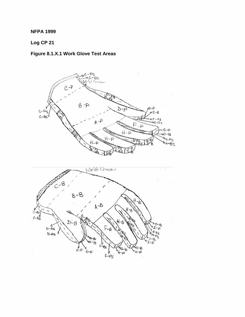
NFPA 1999 Log CP 21 Figure 8.1.X.1 Work Glove Test Areas
Report on Proposals – November 2012 NFPA 1999
Two test subjects, one for hand size small and one for hand size large, shall be selected such that their handdimensions are as close as possible to the middle of the range for hand length and hand circumference as specified bythemanufacturer for small and large gloves.
The time to don one glove of the glove pair specimen shall be determined by measuringthe time it takes for the test subject to don the single glove on three consecutive trials without altering the sample glovelinings between donnings.
Each donning trial shall start with the glove lying in front of the test subject and shall endwhen the test subject’s fingers are seated in the glove sample.
The glove shall be donned in accordance with the manufacturer's donning procedure. The glove shall then beremoved by grasping the fingertip of the middle finger and pulling the hand out of the glove.
The test subject shall be permitted to don either the right hand glove or left hand glove according to individualpreference.
The test subject shall wear the glove of the opposite handing during the test.Where the glove cannot be donned because of detachment of the inner liner or moisture barrier, then the trial
for that glove shall be stopped. If any fingers cannot be fully inserted into the glove, then the trial for that glove shall bestopped.
The baseline donning time shall be the average of the first three donning times as determined in8.30.4.2. The baseline donning time shall not exceed 10 seconds. The doffing time between donnings shall not exceed10 seconds.
The test subject shall repeat the trial specified in 8.30.4.3 for each pair of gloves.Glove pair specimens shall then be conditioned as specified in 8.1.9 8.1.3.
Specimens shall be donned once after removal from the conditioning specified in 8.30.4.10 beforecontinuing testing.
The test subject shall then don one glove of the pair specimen. The test subject shall do this for threeconsecutive trials, for each specimen pair of gloves, as specified in 8.30.4.3 and 8.30.4.9. The times shall be recorded.
The final donning time shall be the average of the times for the first three donnings after removalfrom the final drying cycle as specified in 8.30.4.4 8.30.4.8. No preparation of the gloves shall be done.
The final donning time and the baseline donning time shall be recorded and reported to the nearest 0.1second for each trial.
The average final and average baseline donning times shall be calculated and reported for each specimenglove size.
Pass/fail determinations shall be made using the average final and average baseline donningtimes for each specimen glove size.
This test method shall apply to work gloves.A minimum of three glove pairs each for small and large sizes shall be used for testing.
Specimens shall be tested after being subjected to the procedure specified in 8.1.9 8.1.3.Specimens to be tested shall be conditioned as specified in 8.1.2.
A water-markable glove shall cover all areas of the tester’s hand. The water-markable glove shall beconstructed of a fabric that is easily water-marked to determine leakage.
Water used for integrity testing shall be at a temperature of 20°C, ±3°C (68°F, ±5°F) and treated with anonfoaming surfactant to achieve a surface tension of 35 dynes, ±2 dynes.
The following equipment shall be used for the test procedure:1.) A clear container(s) for submerging gloved hand(s).2.) A stopwatch.
Two test subjects, one for hand size small and one for hand size large, shall be selected such that their handdimensions are as close as possible to the middle of the range for hand length and hand circumference as specified bythe manufacturer for small and large gloves.
The test subject shall don the glove specimen over the water-markable glove.The test subject shall immerse the glove specimen to within 25 mm (1 in.) of the top of the body of the glove
specimen for 5 minutes in 20°C, ±3°C (68°F, ±5°F) water. The test subject shall flex the glove specimen in a fist
25Printed on 7/26/2011
Report on Proposals – November 2012 NFPA 1999clenching motion every 10 seconds.
The glove specimen shall be removed from the testing person’s hand and the inner glove shall be inspectedfor water marks.
After the conditioning described in 8.31.3, the wrist crease location shall be marked as described in X.X.X.Xon each specimen around the entire glove +0/-3 mm (+0/-0.25 in.). Then, in the same manner, the maximum waterheight line shall also be marked on each specimen 25 mm (1 in.) +0/-3 mm (+0/-0.25 in.) below (towards the fingers) thelocation of the wrist crease around the entire glove. Then, in the same manner, the minimum water height line shall alsobe marked on each specimen 50 mm (2 in.) +0/-3 mm (+0/-0.25 in.) below (towards the fingers) the location of the wristcrease around the entire glove.
The test subject shall don the specimen(s) over the water markable glove(s).The test subject shall then immerse the donned specimen(s) straight down into the surfactant treated water to
between the minimum and maximum water height lines for 5 minutes +30/-0 sec. An observer shall be present toensure that the specimen(s) is not immersed beyond the maximum water height line. If the test subject immerses thespecimen(s) beyond the maximum water height line, the specimen(s) shall be retested after air drying and conditioningas specified in 8.1.3. The test subject shall flex the specimen in a gentle, complete fist closing motion every 10 secondswith each fist closing motion taking 10 seconds, +/- 2 seconds to complete. A complete fist closing motion shall bewhen the ends of the glove fingertips make contact with the palm surface of the glove.
The specimen(s) shall then be removed from the test subject's hand, and the water markable glove(s) shall beinspected for water marks.
The appearance of water marks on the inner glove after testing any of the glove pairs shall be recordedand reported.
The appearance of water marks on the inner glove after testing any glove shall be consideredleakage and shall constitute failing performance.
Size small and size large shall be evaluated.Glove pair specimens shall be preconditioned as specified in 8.1.9 and then conditioned as specified in 8.1.2
prior to testing.
Samples shall be taken from the each exterior surface of the work gloves.Work glove samples shall be conditioned as specified in 8.1.9 8.1.3, and then conditioned as specified in
8.1.2.
The technical committee is proposing these changes to Chapter 8 to correlate and harmonize testmethods with recent changes to NFPA 1951 and NFPA 1971.
26Printed on 7/26/2011
Report on Proposals – November 2012 NFPA 1999_______________________________________________________________________________________________1999-27 Log #3 FAE-EMS
_______________________________________________________________________________________________Patricia A. Freeman, Globe Manufacturing Company, LLC
Revise text to read as follows:8.4.3.1 Samples for conditioning shall be the entire complete garment at least 1 m (1 yard) square of material or whole
footwear cover.Many of the garment tests in this standard are required to be done on samples cut from complete
garments that are preconditioned and then cut up to obtain the samples to be tested. It is not necessary to manufacturea complete garment in order to perform tensile strength testing of the fabrics used in construction and the text I amproposing is what is required by NFPA 1971 and other clothing standards. There is precedence for this in the 1999standard, since the biopenetration test is done on the material and the seams and not on samples cut from wholegarments.
The technical committee rejected the proposal because it believes that the interaction of thegarment design and the performance properties of the materials can only be evaluated by preconditioning garments.See 1999-12 (Log #CP2).
_______________________________________________________________________________________________1999-28 Log #4 FAE-EMS
_______________________________________________________________________________________________Patricia A. Freeman, Globe Manufacturing Company, LLC
Revise text to read as follows:8.5.3.1 Samples for conditioning shall be complete garments at least 1 m (1 yard) square of material.
Many of the garment tests in this standard are required to be done on samples cut from completegarments that are preconditioned and then cut up to obtain the samples to be tested. It is not necessary to manufacturea complete garment in order to perform burst strength of the fabrics used in construction and the text I am proposing iswhat is required by NFPA 1971 and other clothing standards. There is precedence for this in the 1999 standard, sincethe biopenetration test is done on the material and the seams and not on samples cut from whole garments.
The technical committee rejected the proposal because it believes that the interaction of thegarment design and the performance properties of the materials can only be evaluated by preconditioning garments.See 1999-12 (Log #CP2).
27Printed on 7/26/2011
Report on Proposals – November 2012 NFPA 1999_______________________________________________________________________________________________1999-29 Log #5 FAE-EMS
_______________________________________________________________________________________________Patricia A. Freeman, Globe Manufacturing Company, LLC
Revise text to read as follows:8.6.3.1 Samples for conditioning shall be complete garments at least 1 m (1 yard) square of material.
Many of the garment tests in this standard are required to be done on samples cut from completegarments that are preconditioned and then cut up to obtain the samples to be tested. It is not necessary to manufacturea complete garment in order to perform puncture propagation tear resistance of the fabrics used in construction and thetext I am proposing is what is required by NFPA 1971 and other clothing standards. There is precedence for this in the1999 standard, since the biopenetration test is done on the material and the seams and not on samples cut from wholegarments.
The technical committee rejected the proposal because it believes that the interaction of thegarment design and the performance properties of the materials can only be evaluated by preconditioning garments.See 1999-12 (Log #CP2).
_______________________________________________________________________________________________1999-30 Log #6 FAE-EMS
_______________________________________________________________________________________________Patricia A. Freeman, Globe Manufacturing Company, LLC
Revise text to read as follows:8.7.3.1 Samples for conditioning shall be complete garments at least 1 m (1 yard) square of material.
Many of the garment tests in this standard are required to be done on samples cut from completegarments that are preconditioned and then cut up to obtain the samples to be tested. It is not necessary to manufacturea complete garment in order to perform tear resistance of the fabrics used in construction and the text I am proposing iswhat is required by NFPA 1971 and other clothing standards. There is precedence for this in the 1999 standard, sincethe biopenetration test is done on the material and the seams and not on samples cut from whole garments.
The technical committee rejected the proposal because it believes that the interaction of thegarment design and the performance properties of the materials can only be evaluated by preconditioning garments.See 1999-12 (Log #CP2).
28Printed on 7/26/2011
Report on Proposals – November 2012 NFPA 1999_______________________________________________________________________________________________1999-31 Log #7 FAE-EMS
_______________________________________________________________________________________________Patricia A. Freeman, Globe Manufacturing Company, LLC
Revise text to read as follows:8.8.3.1 Samples for conditioning shall be complete garments 1 m (1 yard) length of seam.
Many of the garment tests in this standard are required to be done on samples cut from completegarments that are preconditioned and then cut up to obtain the samples to be tested. It is not necessary to manufacturea complete garment in order to perform testing of the seams used in construction and the text I am proposing is what isrequired by NFPA 1971 and other clothing standards. There is precedence for this in the 1999 standard, since thebiopenetration test is done on the material and the seams and not on samples cut from whole garments.
The technical committee rejected the proposal because it believes that the interaction of thegarment design and the performance properties of the materials can only be evaluated by preconditioning garments.See 1999-12 (Log #CP2).
_______________________________________________________________________________________________1999-32 Log #CP6 FAE-EMS
_______________________________________________________________________________________________Technical Committee on Emergency Medical Services Protective Clothing and Equipment,
Change test method paragraph to read as follows:Specimens shall be tested in accordance with ASTM F 1342,
, using Test Method A.
A specific probe must be specified for using this test method.
29Printed on 7/26/2011
Report on Proposals – November 2012 NFPA 1999_______________________________________________________________________________________________1999-33 Log #CP9 FAE-EMS
_______________________________________________________________________________________________Technical Committee on Emergency Medical Services Protective Clothing and Equipment,
Revise Paragraphs 8.25.4.1, 8.37.3.3, and 8.38.10.3 as follows:Protective footwear shall be tested in accordance with FIA Standard 1209, , with the
modification to the test method that water shall not be used. with the following modifications:(1) Water shall not be used.(2) The flex speed shall be 60 +/- 2 cycles per minute.(3) Alternative flexing equipment shall be permitted to be used when the flexing equipment meets the following
parameters:(a) The alternative flexing equipment shall be capable of providing the angle of flex as described in FIA 1209.(b) The alternative flexing equipment shall be capable of a flex speed of 60 +/- 2 cycles per minute.(c) The alternative flexing equipment shall be provide a means of securing the footwear during flexing.
Where the ensemble garment element does not include booties and the [C]BRN barrier layer is incorporatedinto footwear, footwear shall be conditioned by flexing for 100,000 cycles in accordance with Appendix B of FIAStandard 1209, with the following modifications:(1) Water shall not be used.(2) The flex speed shall be 60 +/- 2 cycles per minute.(3) Alternative flexing equipment shall be permitted to be used when the flexing equipment meets the following
parameters:(a) The alternative flexing equipment shall be capable of providing the angle of flex as described in FIA 1209.(b) The alternative flexing equipment shall be capable of a flex speed of 60 +/- 2 cycles per minute.(c) The alternative flexing equipment shall be provide a means of securing the footwear during flexing.
Footwear samples shall be subjected to conditioning by flexing 500,000 cycles in accordance with AppendixB of FIA Standard 1209, with the following modifications:(1) Water shall not be used.(2) The flex speed shall be 60 +/- 2 cycles per minute.(3) Alternative flexing equipment shall be permitted to be used when the flexing equipment meets the following
parameters:(a) The alternative flexing equipment shall be capable of providing the angle of flex as described in FIA 1209.(b) The alternative flexing equipment shall be capable of a flex speed of 60 +/- 2 cycles per minute.(c) The alternative flexing equipment shall be provide a means of securing the footwear during flexing.
The proposed changes align the footwear flexing requirements with other standards in the project,which all currently employ the same requirement. These criteria are necessary because of the lack of currentspecifications for this test equipment.
30Printed on 7/26/2011
Report on Proposals – November 2012 NFPA 1999_______________________________________________________________________________________________1999-34 Log #CP17 FAE-EMS
_______________________________________________________________________________________________Technical Committee on Emergency Medical Services Protective Clothing and Equipment,
Replace existing Section 26 in the current edition of NFPA 1999 with the following:
This method shall apply to cleaning/utility glove materials.Specimens shall be conditioned as specified in 8.1.2.
A minimum of three specimens shall be tested.Specimens with non-uniform surfaces shall be permitted to be treated with an impermeable nonreactive
sealant outside the area of the specimen exposed to the challenge chemical in order to allow sealing of the test cell to auniform surface of the specimen.
Following any sample preparation, the specimens shall be conditioned at a temperature of 32° C +/- 1° C (90°F, +/- 2° F) and at a relative humidity of 80 percent, +/- 5 percent, for at least twenty-four hours prior to testing inaccordance with 8.26.7.1.1
A controlled environmental chamber shall be used to maintain the test cell, air flow control system, andreagent chemicals within +/- 1.0° C (+/- 2.0° F) of the test temperature and +/- 5 percent of the test relative humidity.The controlled environment chamber shall be sized so that it can be used for conditioning test materials, test cells whennot in use, challenge chemicals, and other test apparatus prior to testing, as well as holding the test cells horizontallyduring use while connected to the air delivery system with manifold and to the effluent sampling mechanism.
The test cell shall be a two-chambered cell for contacting the specimen with the challenge chemical on thespecimen’s normal outside surface and for flowing a collection medium on the specimen’s normal inside surface,consisting of parts shown in Figure 8.26.4.2(1) and individual part detail shown in Figures 8.26.4.2(2) through8.26.4.2(6),
An air delivery system and manifold shall be used to provide oil-free, conditioned air to the test cell/fixtures ata rate of 2 standard liters per minute (SLPM) per test cell/fixture with a temperature precision of +/- 0.2° C and a relativehumidity precision of +/- 5 percent. The manifold is designed to deliver 0.3 L/min for the challenge side of the test celland 1 L/min for the collection side of the test cell and maintain at the test temperature. All parts of the air delivery systemand manifold must be chemically inert and non-absorptive to the challenge chemical.
An analytical system shall be used to evaluate the amount of challenge chemical in the effluent air streamsfrom the collection side of the test cell and shall be selected to provide the ability to measure the challenge chemical at0.1 µg/cm2 over the test exposure period. The analytical system shall be permitted to include a bubbler tube, solidsorbent, or real time chemical analyzer. Effluent sampling shall be permitted to be taken discretely or cumulatively;however the selected analytical system shall be able to determine all of the challenge chemical permeating through the
31Printed on 7/26/2011
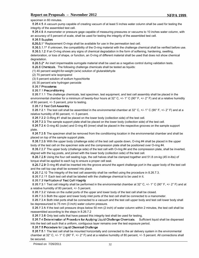
Report on Proposals – November 2012 NFPA 1999specimen in 60 minutes.
A vacuum pump capable of creating vacuum of at least 5 inches water column shall be used for testing theintegrity of the assembled test cell.
A manometer or pressure gage capable of measuring pressures or vacuums to 10 inches water column, withan accuracy of 5 percent of scale, shall be used for testing the integrity of the assembled test cell.
* Replacement O-rings shall be available for use in the permeation test cell.If unknown, the compatibility of the O-ring material with the challenge chemical shall be verified before use.
If an O-ring shows any signs of chemical degradation in the form of softening, hardening, swelling,deterioration, or loss of shape, or function, an O-ring of different material shall be used that does not show chemicaldegradation.
An inert impermeable surrogate material shall be used as a negative control during validation tests.The following challenge chemicals shall be tested as liquids:
(1) 40 percent weight-for-weight (w/w) solution of glutaraldehyde(2) 70 percent w/w isopropanol(3) 5 percent solution of sodium hypochlorite(4) 30 percent w/w hydrogen peroxide
The challenge chemicals, test specimen, test equipment, and test cell assembly shall be placed in theenvironmental chamber for a minimum of twenty-four hours at 32° C, +/- 1° C (90° F, +/- 2° F) and at a relative humidityof 80 percent, +/- 5 percent, prior to testing.
The test cell shall be assembled in the environmental chamber at 32° C, +/- 1° C (90° F, +/- 2° F) and at arelative humidity of 80 percent, +/- 5 percent.
O-Ring #1 shall be placed on the lower body (collection side) of the test cell.The sample support plate shall be placed on the lower body (collection side) of the test cell.O-ring #2 (outer) and O-ring #3 (inner) shall be placed in the respective grooves on the sample support
plate.The specimen shall be removed from the conditioning location in the environmental chamber and shall be
placed on top of the sample support plate.With the upper body (challenge side) of the test cell upside down, O-ring #4 shall be placed in the upper
body of the test cell on the specimen side and the compression plate shall be positioned over O-ring #4.The upper body (challenge side) of the test cell with O-ring #4 and the compression plate, shall be inverted,
aligned with the lug posts, and joined with the lower body (collection side) of the test cell.Using the four cell sealing lugs, the cell halves shall be clamped together and 51.8 cm-kg (45 in-lbs) of
torque shall be applied to each lug to ensure a proper cell seal.O-ring #5 shall be inserted into the groove around the agent challenge port in the upper body of the test cell
and the cell top cap shall be screwed into place.The integrity of the test cell assembly shall be verified using the procedure in 8.26.7.3.Each test cell shall be labeled with the challenge chemical to be used in it.
Test cell integrity shall be performed in the environmental chamber at 32° C, +/- 1° C (90° F, +/- 2° F) and ata relative humidity of 80 percent, +/- 5 percent.
Valves on the outlet ports of the upper and lower body of the test cell shall be closed.Both the upper and lower body inlet ports of the test cell shall be connected to a manometer.Both inlet ports shall be connected to a vacuum and the test cell upper body and test cell lower body shall
be depressurized to 75 mm (3 inch) water column pressure.If the test cell pressure drops below 50 mm (2 inch) of water column within 2 minutes, the test cell shall be
reassembled according to the steps in 8.26.7.2Only test cells that have passed this integrity test shall be used for testing.
Sufficient liquid shall be dispensedinto the test cell such that a uniform, contiguous layer remains over the test exposure period.
The test cell shall be mounted horizontally and connected to the air delivery system in the environmentalchamber at 32° C, +/- 1° C (90° F, +/- 2° F) and at a relative humidity of 80 percent, +/- 5 percent. All connections shallbe secured.
32Printed on 7/26/2011
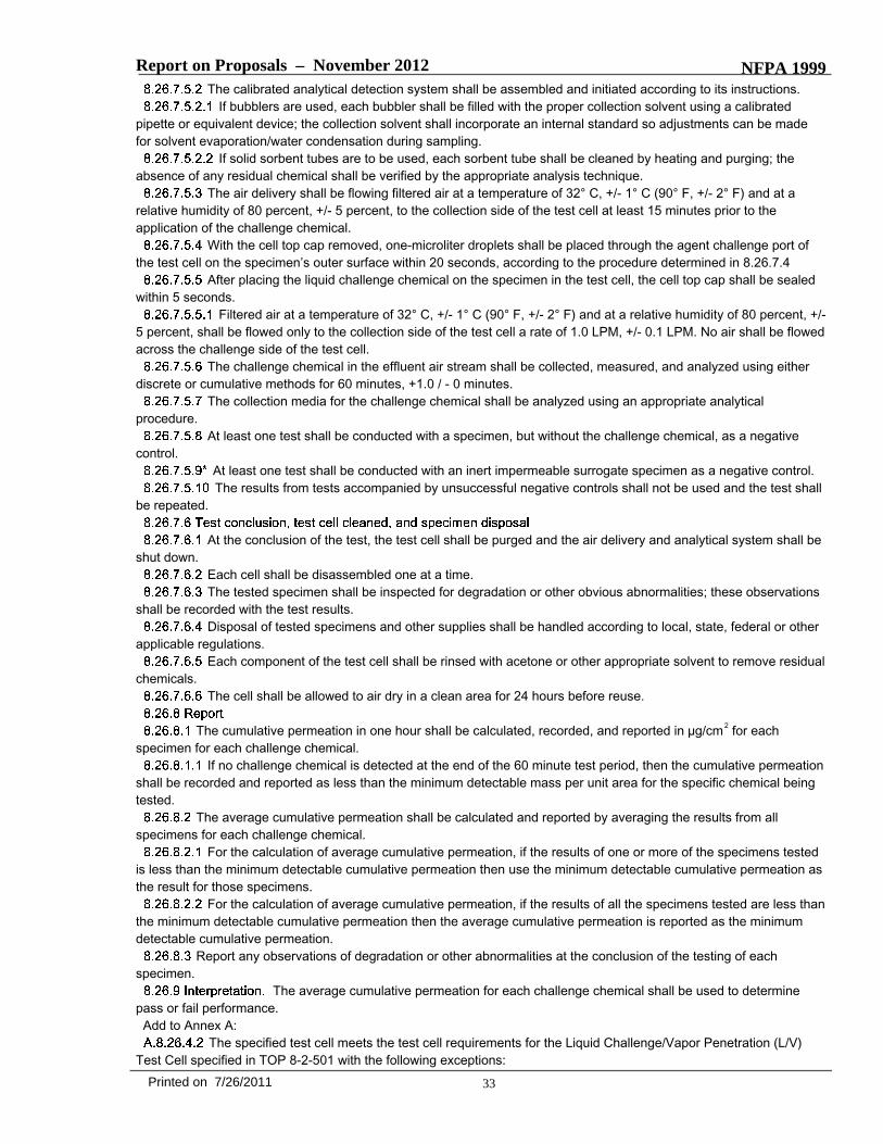
Report on Proposals – November 2012 NFPA 1999The calibrated analytical detection system shall be assembled and initiated according to its instructions.
If bubblers are used, each bubbler shall be filled with the proper collection solvent using a calibratedpipette or equivalent device; the collection solvent shall incorporate an internal standard so adjustments can be madefor solvent evaporation/water condensation during sampling.
If solid sorbent tubes are to be used, each sorbent tube shall be cleaned by heating and purging; theabsence of any residual chemical shall be verified by the appropriate analysis technique.
The air delivery shall be flowing filtered air at a temperature of 32° C, +/- 1° C (90° F, +/- 2° F) and at arelative humidity of 80 percent, +/- 5 percent, to the collection side of the test cell at least 15 minutes prior to theapplication of the challenge chemical.
With the cell top cap removed, one-microliter droplets shall be placed through the agent challenge port ofthe test cell on the specimen’s outer surface within 20 seconds, according to the procedure determined in 8.26.7.4
After placing the liquid challenge chemical on the specimen in the test cell, the cell top cap shall be sealedwithin 5 seconds.
Filtered air at a temperature of 32° C, +/- 1° C (90° F, +/- 2° F) and at a relative humidity of 80 percent, +/-5 percent, shall be flowed only to the collection side of the test cell a rate of 1.0 LPM, +/- 0.1 LPM. No air shall be flowedacross the challenge side of the test cell.
The challenge chemical in the effluent air stream shall be collected, measured, and analyzed using eitherdiscrete or cumulative methods for 60 minutes, +1.0 / - 0 minutes.
The collection media for the challenge chemical shall be analyzed using an appropriate analyticalprocedure.
At least one test shall be conducted with a specimen, but without the challenge chemical, as a negativecontrol.
At least one test shall be conducted with an inert impermeable surrogate specimen as a negative control.The results from tests accompanied by unsuccessful negative controls shall not be used and the test shall
be repeated.
At the conclusion of the test, the test cell shall be purged and the air delivery and analytical system shall beshut down.
Each cell shall be disassembled one at a time.The tested specimen shall be inspected for degradation or other obvious abnormalities; these observations
shall be recorded with the test results.Disposal of tested specimens and other supplies shall be handled according to local, state, federal or other
applicable regulations.Each component of the test cell shall be rinsed with acetone or other appropriate solvent to remove residual
chemicals.The cell shall be allowed to air dry in a clean area for 24 hours before reuse.
The cumulative permeation in one hour shall be calculated, recorded, and reported in µg/cm2 for eachspecimen for each challenge chemical.
If no challenge chemical is detected at the end of the 60 minute test period, then the cumulative permeationshall be recorded and reported as less than the minimum detectable mass per unit area for the specific chemical beingtested.
The average cumulative permeation shall be calculated and reported by averaging the results from allspecimens for each challenge chemical.
For the calculation of average cumulative permeation, if the results of one or more of the specimens testedis less than the minimum detectable cumulative permeation then use the minimum detectable cumulative permeation asthe result for those specimens.
For the calculation of average cumulative permeation, if the results of all the specimens tested are less thanthe minimum detectable cumulative permeation then the average cumulative permeation is reported as the minimumdetectable cumulative permeation.
Report any observations of degradation or other abnormalities at the conclusion of the testing of eachspecimen.
The average cumulative permeation for each challenge chemical shall be used to determinepass or fail performance.Add to Annex A:
The specified test cell meets the test cell requirements for the Liquid Challenge/Vapor Penetration (L/V)Test Cell specified in TOP 8-2-501 with the following exceptions:
33Printed on 7/26/2011
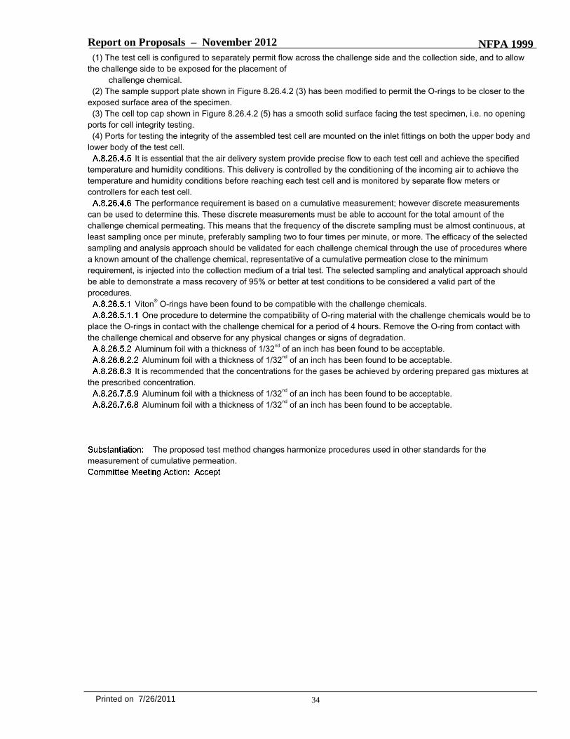
Report on Proposals – November 2012 NFPA 1999(1) The test cell is configured to separately permit flow across the challenge side and the collection side, and to allow
the challenge side to be exposed for the placement ofchallenge chemical.
(2) The sample support plate shown in Figure 8.26.4.2 (3) has been modified to permit the O-rings to be closer to theexposed surface area of the specimen.(3) The cell top cap shown in Figure 8.26.4.2 (5) has a smooth solid surface facing the test specimen, i.e. no opening
ports for cell integrity testing.(4) Ports for testing the integrity of the assembled test cell are mounted on the inlet fittings on both the upper body and
lower body of the test cell.It is essential that the air delivery system provide precise flow to each test cell and achieve the specified
temperature and humidity conditions. This delivery is controlled by the conditioning of the incoming air to achieve thetemperature and humidity conditions before reaching each test cell and is monitored by separate flow meters orcontrollers for each test cell.
The performance requirement is based on a cumulative measurement; however discrete measurementscan be used to determine this. These discrete measurements must be able to account for the total amount of thechallenge chemical permeating. This means that the frequency of the discrete sampling must be almost continuous, atleast sampling once per minute, preferably sampling two to four times per minute, or more. The efficacy of the selectedsampling and analysis approach should be validated for each challenge chemical through the use of procedures wherea known amount of the challenge chemical, representative of a cumulative permeation close to the minimumrequirement, is injected into the collection medium of a trial test. The selected sampling and analytical approach shouldbe able to demonstrate a mass recovery of 95% or better at test conditions to be considered a valid part of theprocedures.
Viton® O-rings have been found to be compatible with the challenge chemicals.One procedure to determine the compatibility of O-ring material with the challenge chemicals would be to
place the O-rings in contact with the challenge chemical for a period of 4 hours. Remove the O-ring from contact withthe challenge chemical and observe for any physical changes or signs of degradation.
Aluminum foil with a thickness of 1/32nd of an inch has been found to be acceptable.Aluminum foil with a thickness of 1/32nd of an inch has been found to be acceptable.
It is recommended that the concentrations for the gases be achieved by ordering prepared gas mixtures atthe prescribed concentration.
Aluminum foil with a thickness of 1/32nd of an inch has been found to be acceptable.Aluminum foil with a thickness of 1/32nd of an inch has been found to be acceptable.
The proposed test method changes harmonize procedures used in other standards for themeasurement of cumulative permeation.
34Printed on 7/26/2011
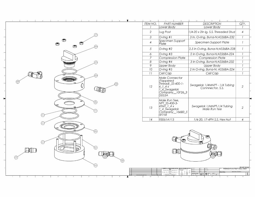
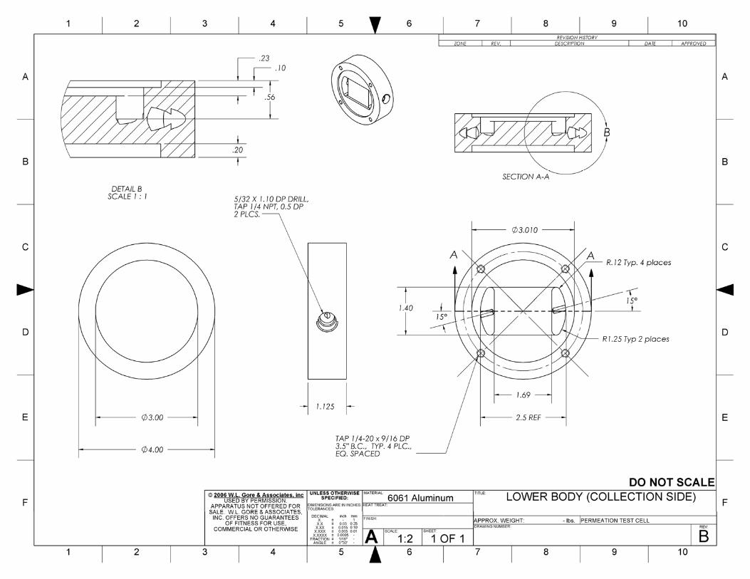
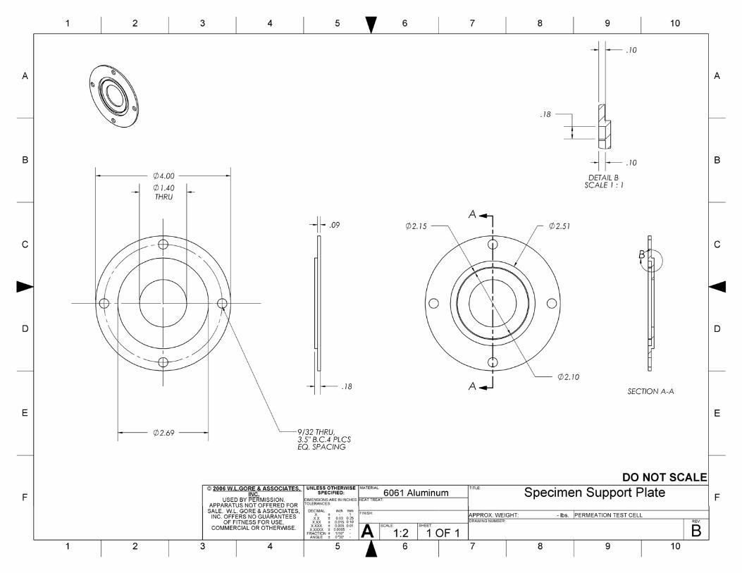
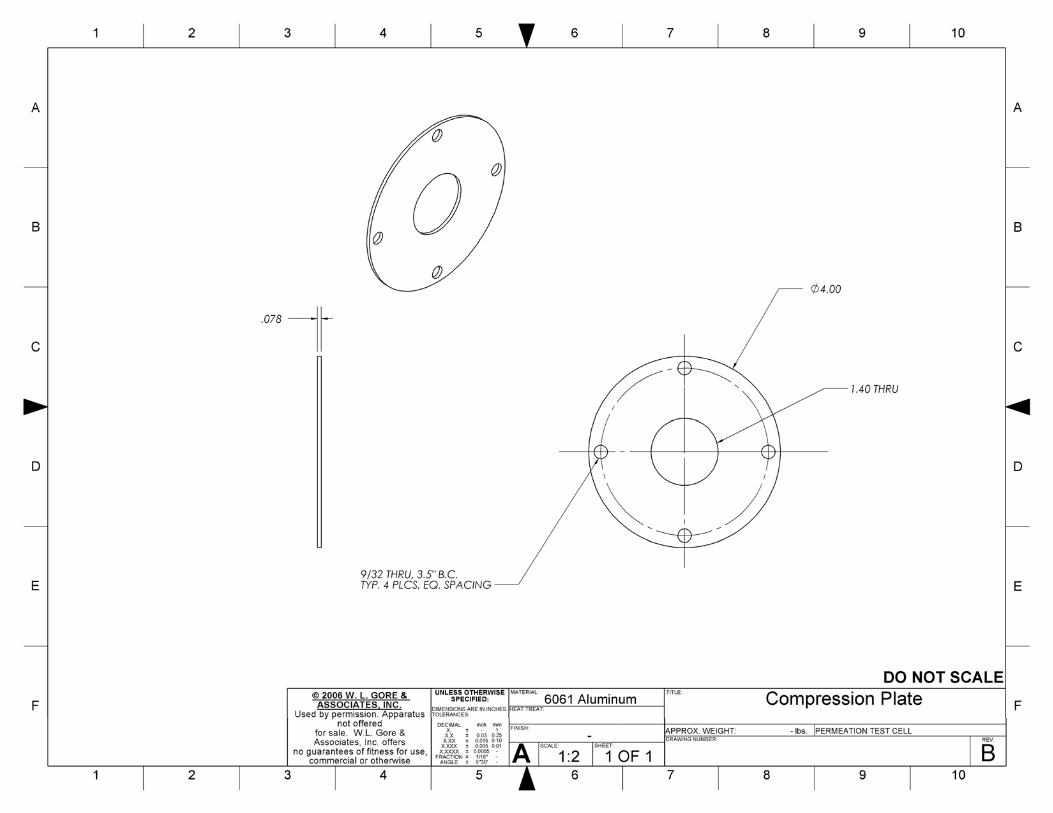

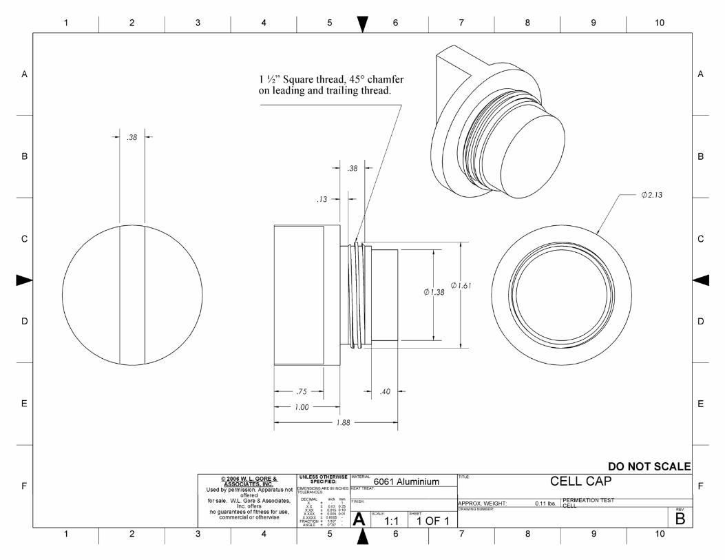
Report on Proposals – November 2012 NFPA 1999_______________________________________________________________________________________________1999-35 Log #16 FAE-EMS
_______________________________________________________________________________________________Mark A. Williams, W. L. Gore & Associates
8.31.5.X The wrist crease location shall be marked on each test specimen glove as described in Section 6.2.3 after theconditioning described in Section 8.33.3. At the location of the wrist crease, the maximum water height line shall bedrawn on each test specimen glove around the entire glove 50 mm (2 in.) +0/-3 mm (+0/-0.25 in.) towards the fingers. Inthe same manner, the minimum water height line shall be drawn on each test specimen glove 75 mm (3 in.) +0/-3 mmtowards the fingers from the wrist crease around the entire glove +0/-3 mm (+0/-0.25 in.).
8.31.5.3 The test subject shall then immerse the donned glove specimens straight down into the surfactant treatedwater to the between the minimum and maximum water height line for 5 minutes +30/-0 sec. An observer shall bepresent to ensure that the glove is not immersed beyond the maximum water height line. If the test subject immerses theglove beyond the maximum water height line, the glove shall be retested after air drying and conditioning as specified in8.1.3 The test subjects wrists shall be secured during the test in such a manner that the fingers shall touch the bottom ofthe water tank and the movement of the hands/arms are minimized in any direction so that the water does not fall aboveor below the water height mark at location on the glove. The test subject shall flex the glove specimen in a gentle,complete (but not tight) fist-clenching motion until the fingertips touch the palm every 10 seconds with eachfist-clenching motion taking 10 +2/-2 second to complete.
NFPA 1971 Glove Task Group members supported this change.The goals of the NFPA 1971 Glove Task Group during this revision cycle included:
Improve the reproducibility of glove tests within lab and lab-to-lab.Problem: The current version of this test is very difficult to perform without splashing and pumping water up to the end
of the glove body composite. This gives a false failure result.Solution: The proposed revised text solves the reproducibility problem without making a relatively simple test
complicated by giving a larger tolerance on how precisely the test subject must hold their arm in the water:1) The water height line is moved below the wrist crease at least 2 inches from the end of the glove body2) The test subject is given a large tolerance +0/-1 in. to maintain the water height—effectively at least 2-to-3 inches
from the end of the glove body.3) An observer is present to ensure that both the test subject and the observer can call for a retest if the water goes
above the water height line.Substantiation: The goal of this test is to identify leakage in the glove body and to identify glove shell materials that
wick liquids up to the cuff and into the liner. The changes recommended in this public comment bring the test closer tohow it was practiced in the 1990’s before the beginning of the numerous false failures we are experiencing today. NFPA1999-2008 edition included flexing the glove specimen while submerged in the water to within 1 in. (no tolerance stated)of the end of the glove body composite. This protocol had the unfortunate side-effect of making the glove difficult to holdstraight. Also, vigorous flexing action close to the cuff can sometimes create pumping action that forces water up to theliner and down into the glove. However, the flexing action is an important part of the test since it ensures that asufficient volume of water goes through any holes and is transferred to the marker glove.The recommended text solves the reproducibility problem without changing the mechanics of the test that have been in
practice for over 20 years. It also keeps the test simple. Additionally, other standards such as NFPA 1951 have electedto continue flexing the hand in the water.
35Printed on 7/26/2011
Report on Proposals – November 2012 NFPA 1999_______________________________________________________________________________________________1999-36 Log #CP22 FAE-EMS
_______________________________________________________________________________________________Technical Committee on Emergency Medical Services Protective Clothing and Equipment,
Revise paragraph 8.34.5 as follows:Testing shall be conducted in accordance with Part C of ASTM F 1868,
with the following modifications:(1) The specimen shall be placed on the test plate with the side normally facing the human body toward the test plate.(2) For multiple layers, the layers shall be arranged in the order and orientation as worn.(3) Each layer shall be smoothed by hand to eliminate wrinkles or bubbles in each layer and, if necessary, the edges
shall be secured.(4)* Once the test is started, no further adjustments to the specimen shall be made.Add the following paragraph to Annex A:
These modifications should be used instead of Note 6 in ASTM F1868, Part C.
hese changes harmonize the total heat loss test procedures with other standards in the project. Thenew revision of ASTM F 1868 has introduced new techniques via Note 6 for handling composites that distortdimensionally during the test. The standard values of performance in Total Heat Loss testing are dependent on the testparameters and procedures. By modifying the testing and handling techniques of the specimen, Note 6 has theunintended consequence of modifying standard values. It can allow material systems that previously failed therequirements to pass. Furthermore, the instructions are biased and unclear. For example, in a multi-layer composite, it isdifficult to determine, which layer, if any, is not laying flat per Note 6. By preferentially re-smoothing one or more of thelayers in one composite, and not all layers, or not all composites, Note 6 introduces bias. It is unclear when to implementNote 6 or which parts of Note 6. When is a flat specimen no longer flat? It also introduces a bias by assuming materialsonly change dimensionally under the conditions of the test, and therefore preferentially attempts to correct for only thisrecognizes.
_______________________________________________________________________________________________1999-37 Log #8 FAE-EMS
_______________________________________________________________________________________________Patricia A. Freeman, Globe Manufacturing Company, LLC
Revise text to read as follows:8.39.2.1 A minimum of three test specimens shall be tested as removed from conditioned garments following
conditioning as specified in 8.39.3. Samples for conditioning shall include 305 mm (12 in) long sections of trim.Many of the garment tests in this standard are required to be done on samples cut from complete
garments that are preconditioned and then cut up to obtain the samples to be tested. It is not necessary to manufacturea complete garment in order to perform retro reflectivity and fluorescence testing on the trim used in construction. Thetext I am proposing is what is required by NFPA 1971 and other clothing standards.
The technical committee rejected the proposal because it believes that the interaction of thegarment design and the performance properties of the materials can only be evaluated by preconditioning garments.See 1999-12 (Log #CP2).
36Printed on 7/26/2011
Report on Proposals – November 2012 NFPA 1999_______________________________________________________________________________________________1999-38 Log #9 FAE-EMS
_______________________________________________________________________________________________Patricia A. Freeman, Globe Manufacturing Company, LLC
Revise text to read as follows:8.40.3.1 Samples for conditioning shall be complete garments at least 1 m (1 yard) square of material.
Many of the garment tests in this standard are required to be done on samples cut from completegarments that are preconditioned and then cut up to obtain the samples to be tested. It is not necessary to manufacturea complete garment in order to perform tear resistance of the fabrics used in construction and the text I am proposing iswhat is required by NFPA 1971 and other clothing standards. There is precedence for this in the 1999 standard, sincethe biopenetration test is done on the material and the seams and not on samples cut from whole garments.
The technical committee rejected the proposal because it believes that the interaction of thegarment design and the performance properties of the materials can only be evaluated by preconditioning garments.See 1999-12 (Log #CP2).
_______________________________________________________________________________________________1999-39 Log #10 FAE-EMS
_______________________________________________________________________________________________Patricia A. Freeman, Globe Manufacturing Company, LLC
Revise text to read as follows:8.41.7.3 Samples for conditioning shall be the entire complete garments at least 1 m (1 yard) square of material.
Many of the garment tests in this standard are required to be done on samples cut from completegarments that are preconditioned and then cut up to obtain the samples to be tested. It is not necessary to manufacturea complete garment in order to perform flame testing of the fabrics used in construction and the text I am proposing iswhat is required by NFPA 1971 and other clothing standards. There is precedence for this in the 1999 standard, sincethe biopenetration test is done on the material and the seams and not on samples cut from whole garments.
The technical committee rejected the proposal because it believes that the interaction of thegarment design and the performance properties of the materials can only be evaluated by preconditioning garments.See 1999-12 (Log #CP2).
37Printed on 7/26/2011
Report on Proposals – November 2012 NFPA 1999_______________________________________________________________________________________________1999-40 Log #2 FAE-EMS
_______________________________________________________________________________________________
Jeffrey O. Stull, International Personnel Protection, Inc.Add new annex item address selection factors for consideration by end users for different types of
emergency medical protective clothing. Suggested annex to be provided at ROC meeting.Additional guidance should be provided to first responders in the selection of protective clothing
covered by the standard, particularly in the absence of a selection, care, and maintenance standard. This information isappropriate as an appendix item, ideally as a separate appendix so that it can clearly be identified by prospective endusers referring to the standard.
Add the following text to Annex A:A.1.1.6 This standard provides a range of different types of protective clothing and equipment that can be used in the
provision of emergency patient care and transportation prior to arrival at a medical care facility by emergency medicalresponders, emergency patient care by medical first receivers at a medical care facility, and body recovery byemergency medical responders. The selection of protective clothing and equipment for emergency medical operationsshould account for a hazard assessment undertaken by the department or organization that is responsible foremployees that are involved in emergency medical operations. The hazard assessment should be performed inaccordance with Title 29, Code of Federal Regulations, Part 1910.132, “General Requirements of Subpart I, PersonalProtective Equipment,” to ensure compliance with Title 29, Code of Federal Regulations, Part 1910.1030, “ProtectingHealth Care Workers from Occupational Exposure to Blood-Borne Pathogens,” or the applicable local, state, regional, ornational regulations.The hazard assessment should identify the specific risks of emergency medical responders or medical first receivers to
hazards that include, but are not limited to those listed in Table A.1.1.6 (1).
****INSERT TABLE A.1.1.6(1) HERE ****
It is important to recognize that the protective clothing specified in this standard does not protect against all of thehazards listed in Table A.1.1.6 (1).In identifying the potential hazards, the department or organization should determine the likelihood of exposure and the
consequence of exposure. The combination of these two factors should establish the risk of exposure and should permitthe prioritization of protection needs.As the requirements in this standard were designed to provide individuals with some protection against hazards
associated with bloodborne pathogen exposure, it is important that the selected clothing and equipment enable thedepartment or organization to comply with Title 29, Code of Federal Regulations, Part 1910.1030, “Protecting HealthCare Workers from Occupational Exposure to Blood-Borne Pathogens.” These regulations require that employers(departments and organizations) provide appropriate protective clothing and equipment to their workers. Appropriateprotective clothing and equipment is defined as those items that prevent blood and other infectious liquids from passthrough the clothing or equipment item to the wearer’s skin or under clothing. For this reason, a principal component ofmost clothing and equipment requirements in this standard is a test that demonstrates the barrier performance of theitem and the material in preventing liquid penetration. Additional requirements are added to demonstrate that therespective clothing or equipment item provides some degree of protection against other hazards that are relevant to theuse of that item that might commonly be anticipated as part of emergency medical operations.As part of the hazard and risk assessment conducted by the department or organization, it is important that the
department or organization consider which portions of the body that exposure may occur. Exposures may occur to thebody (including arms and legs), head, eyes and face, hands, feet, respiratory system, and hearing. Protective clothingand equipment should be specified for any body area that is at risk of exposure.Table A.1.1.6 (2) provides some factors for consideration of each of the protective clothing items addressed in this
standard.
38Printed on 7/26/2011

Report on Proposals – November 2012 NFPA 1999
***INSERT TABLE A.1.1.6 (2) HERE***
The technical committee accepted the proposal in principle, and provided the Annex text asshown in the meeting action.
39Printed on 7/26/2011

1999/L2/Tb A.1.1.6(1)/F2012/ROP
Table A.1.1.6(1) List of Potential Emergency Medical and Related Hazards Biological Hazards Bloodborne pathogens Airborne pathogens Biological toxins Biological allergens Chemical Hazards Inhalation Skin absorption or contact Chemical ingestion or injection Liquefied gas contact Chemical flashover Chemical explosions Physical Hazards Falling objects Flying debris Projectiles or ballistic objects Abrasive or rough surfaces Pointed objects Slippery surfaces Excessive vibration Environmental Hazards High heat and humidity Ambient cold Wetness High wind Insufficient or bright light Excessive noise Radiation Hazards Ionizing radiation Non-ionizing radiation
Thermal Hazards High convective heat Low radiant heat High radiant heat Flame impingement Steam Hot liquids Molten metals Hot solids Hot surfaces Electrical Hazards High voltage Electrical arc flashover Static charge buildup Person-Position Hazards Daytime and nighttime visibility Falling from elevated surfaces Drowning Person-Equipment Hazards Material biocompatibility Ease of contamination Thermal comfort Range of motion Hand function Ankle and back support Vision clarity Communications ease Fit (poor) Ease of donning and doffing
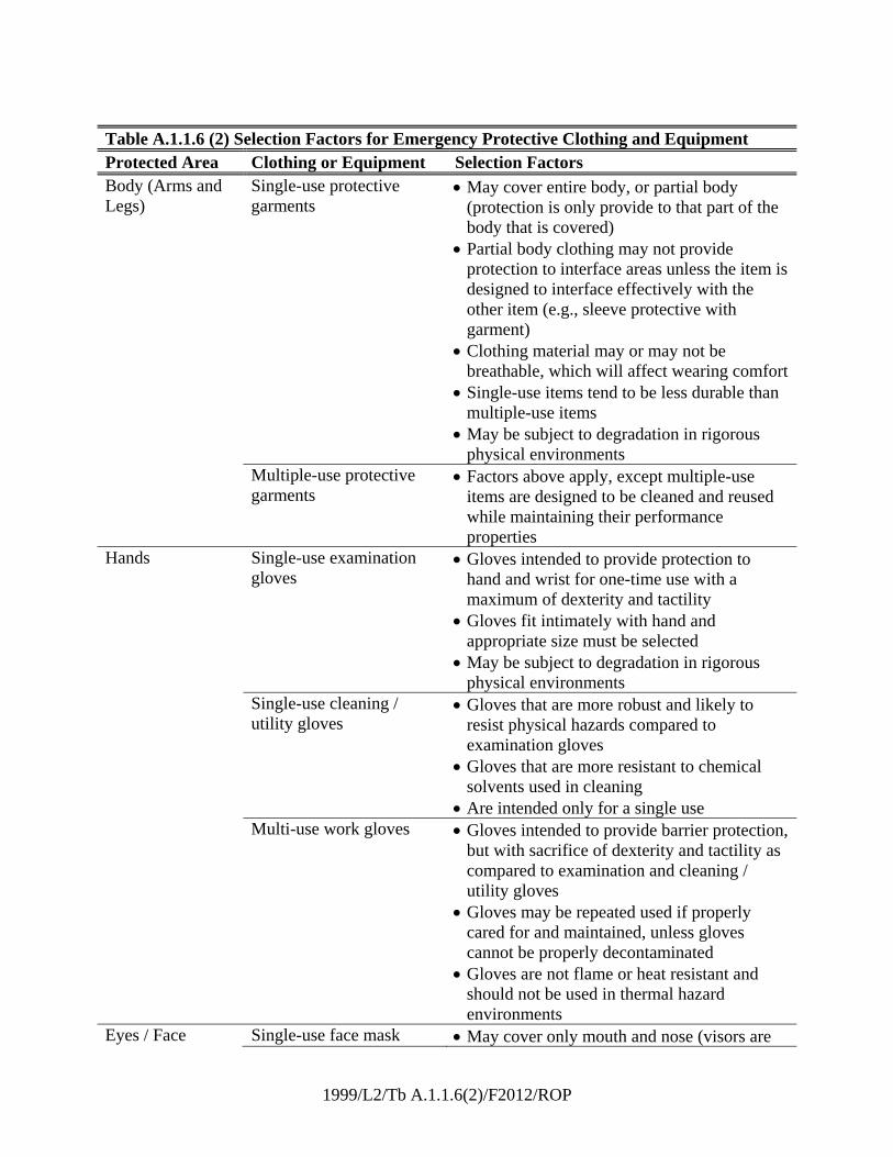
1999/L2/Tb A.1.1.6(2)/F2012/ROP
Table A.1.1.6 (2) Selection Factors for Emergency Protective Clothing and Equipment Protected Area Clothing or Equipment Selection Factors Body (Arms and Legs)
Single-use protective garments
May cover entire body, or partial body (protection is only provide to that part of the body that is covered)
Partial body clothing may not provide protection to interface areas unless the item is designed to interface effectively with the other item (e.g., sleeve protective with garment)
Clothing material may or may not be breathable, which will affect wearing comfort
Single-use items tend to be less durable than multiple-use items
May be subject to degradation in rigorous physical environments
Multiple-use protective garments
Factors above apply, except multiple-use items are designed to be cleaned and reused while maintaining their performance properties
Hands Single-use examination gloves
Gloves intended to provide protection to hand and wrist for one-time use with a maximum of dexterity and tactility
Gloves fit intimately with hand and appropriate size must be selected
May be subject to degradation in rigorous physical environments
Single-use cleaning / utility gloves
Gloves that are more robust and likely to resist physical hazards compared to examination gloves
Gloves that are more resistant to chemical solvents used in cleaning
Are intended only for a single use Multi-use work gloves Gloves intended to provide barrier protection,
but with sacrifice of dexterity and tactility as compared to examination and cleaning / utility gloves
Gloves may be repeated used if properly cared for and maintained, unless gloves cannot be properly decontaminated
Gloves are not flame or heat resistant and should not be used in thermal hazard environments
Eyes / Face Single-use face mask May cover only mouth and nose (visors are
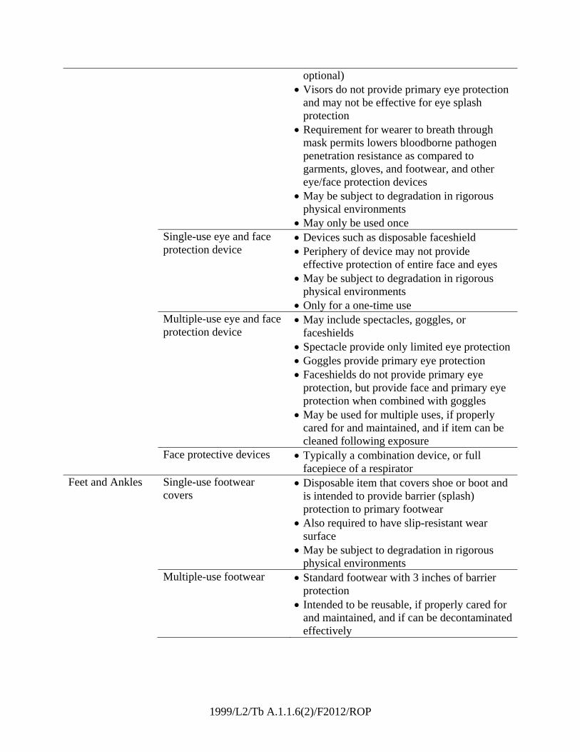
1999/L2/Tb A.1.1.6(2)/F2012/ROP
optional) Visors do not provide primary eye protection
and may not be effective for eye splash protection
Requirement for wearer to breath through mask permits lowers bloodborne pathogen penetration resistance as compared to garments, gloves, and footwear, and other eye/face protection devices
May be subject to degradation in rigorous physical environments
May only be used once Single-use eye and face
protection device Devices such as disposable faceshield Periphery of device may not provide
effective protection of entire face and eyes May be subject to degradation in rigorous
physical environments Only for a one-time use
Multiple-use eye and face protection device
May include spectacles, goggles, or faceshields
Spectacle provide only limited eye protection Goggles provide primary eye protection Faceshields do not provide primary eye
protection, but provide face and primary eye protection when combined with goggles
May be used for multiple uses, if properly cared for and maintained, and if item can be cleaned following exposure
Face protective devices Typically a combination device, or full facepiece of a respirator
Feet and Ankles Single-use footwear covers
Disposable item that covers shoe or boot and is intended to provide barrier (splash) protection to primary footwear
Also required to have slip-resistant wear surface
May be subject to degradation in rigorous physical environments
Multiple-use footwear Standard footwear with 3 inches of barrier protection
Intended to be reusable, if properly cared for and maintained, and if can be decontaminated effectively

1999/L2/Tb A.1.1.6(2)/F2012/ROP
Medical care facility footwear
Same as above, but does not have requirements for impact/compression resistance for toe and puncture resistance of sole, allowing footwear to be lighter and more flexible
Head Helmet Standard industrial helmet that also includes requirements for suspension and chin strap height
No specific criteria are included for side impact protection as may occur for wearers inside vehicles