Embed Size (px)
Citation preview

M-1500/2000 Power Amplifier
POWER
40dB PROTCLIP40dB 20dB20dBCLIPPROT
POWER AMPLIFIERM200017
22
13
10
01
22954
19
15
1112
98
7
5
4
3
6
17
22
13
10
01
22954
19
15
1112
98
7
5
4
3
6

ContentsContents1. Unpacking and Installation.....................................................................................................1
2. Features ................................................................................................................................2
3. Front Panel Controls...............................................................................................................3
4. Rear Panel Controls ...............................................................................................................4
5. Protection Circuitry.................................................................................................................6
6. Bridged and Parallel Modes ...................................................................................................7
7. Connections...........................................................................................................................8
8. Link Connectors .....................................................................................................................9
9. Speaker Impedance ...............................................................................................................9
10. Caution for Speaker Connection .........................................................................................10
11. Portable Rack Mounting .....................................................................................................11
12. Positioning the Housed Amplifier ........................................................................................12
13. Troubleshooting.................................................................................................................12
14. Block Diagram...................................................................................................................13
15. Specifications.....................................................................................................................14
OFFICE :226-9 DUGJUNG - LI, HOE CHUN - EUB, YANGJU - KUN, KYUNGKI - DO, KOREA TEL : 82-351-860-7041~5, FAX : 82-351-858-1907
Home Page : http://www.inter-m.co.krE-mail : [email protected]

Unpacking and InstallationUnpacking and Installation
Although it is neither complicated to install nor difficult to operate your power Amplifier, a few minutes ofyour time is required to read this manual for a properly wired installation and becoming familiar with itsmany features and how to use them. Please take a great care in unpacking your set and do not discard thecarton and other packing necessary to return your set for when moving your set and are required if it everbecomes necessary to return your set for service. Never place the unit near radiators, in front of heatingvents, to direct sun light, in excessive humid or dusty location to avoid early damage and for your years ofquality use. Connect your complementary components as illustrated in the following page.
M-1500/2000 1
POWER AMPLIFIER
RISK OF ELECTRIC SHOCKDO NOT OPEN
CAUTION
CAUTION: TO REDUCE THE RISK OF ELECTRIC SHOCK.
DO NOT REMOVE COVER (OR BACK).
NO USER-SERVICEABLE PARTS INSIDE.
REFER SERVICING TO QUALIFIED SERVICE PERSONNEL.
WARNING
To prevent fire or shock hazard, do notexpose the unit to rain or moisture.
This symbol is intended to alert the user to thepresence of uninsulated “dangerous voltage”within the product’s enclosure that may be of suf-ficient magnitude to constitute a risk of electricshock to persons.
This symbol is intended to alert the user to thepresence of important operation and mainte-nance (servicing) instructions in the literatureaccompanying the appliance.
Caution: To prevent electric shock do not use this (polarized) plugwith an extension cord, receptacle or other outlet unlessthe blades can be fully inserted to prevent blade expo-sure.
Attentions: Pour prévenir les chocs électriques ne pas utiliser cettefiche polarisée avec un prolongateur, une prise decourant on une autre sortie de courant, sauf si leslames peuvent étre insérées à fond sans en laisseraucune partie à découvert.

Features
M-1500/20002
POWER AMPLIFIER
Features- SUBSTANTIAL PROTECTION CIRCUITARY
To insure stability and reliability against over current and overheating extra protection circuitary is provid-ed. In addition, turn on delay and DC detection circuitary is provided to protect the loud-speaker.
- BRIDGED MONO FUNCTIONThese stereo amplifiers can be used for monoral powerful sound by selecting the mode switch.
- VARIOUS DISPLAYTo confirm the operating status, LED displays of protection, clip, and signals are provided on front panel.
- COMPACT SIZEFor valuable saving in rack space and slim exterior view, these amplifier is designed within compact size.
- SOFT-START SYSTEMTo prevent inrush current when turn on the amplifier, soft-start circuit is provided on primary power lines.
- SPEED CONTROLLED FANDual temperature-sensitive speed-controlled fans for reliable cooling without thermal and overheating prob-lems.
- COMBINATION INPUT CONNECTORCombination input connectors for each channel accommodate both balanced XLR or balanced 1/4” TRSplugs, as well as both SpeakonTM and banana jack output connectors for maximum flexibility.
- TRANSFORMERToroidal transformer power supply for high current and low profile.
Front Panel ControlsFront Panel ControlsFront Panel Controls
1. PROTECTION INDICATORThis red LED indicator lights up for approximately six seconds when the amplifier is powered ON, indi-cating that the soft-start protection system is working. No sound is output during soft-start up. If one ofthe protection systems is activated during normal use, this indicator lights up and no sound is output. Thespeaker system is actually disconnected from the amplifier outputs when this indicator lights up. The pro-tection systems are activated when overheating occurs or a DC voltage is present at the amplifier out-puts. If the problem is corrected, the protection systems deactivate automatically, this indicator goes out,and normal amplifier operation is resumed.
2. CLIP INDICATORSCLIP indicator on each channel illuminates when distortion reaches or exceeds approximately 0.1%,indicating that the amplifier is being driven by excessively high inputs.
3. OUTPUT LEVEL INDICATORSOutput level indicating LEDs indicate the output level of this amplifiers. These LEDs illuminate when theoutputs are –40dB and –20dB of rated power.
4. INPUT ATTENUATORSSeparate level controls are provided for channel one and channel two input, clockwise rotation of thecontrols increase level. These are 21-step detented input signal attenuators.
5. POWER SWITCH AND INDICATORThe power switch is used to turn on and off the AC main power.The power indicator lights up when the amplifier is powered ON.
6. HANDLESYou can handle this amplifier easily by using these handles.
M-1500/2000 3
POWER AMPLIFIER
POWER
40dB PROTCLIP40dB 20dB20dBCLIPPROT
POWER AMPLIFIERM200017
22
13
10
01
22954
19
15
1112
98
7
5
4
3
6
17
22
13
10
01
22954
19
15
1112
98
7
5
4
3
6
6 65
1 2 43 123

4 M-1500/2000
POWER AMPLIFIER
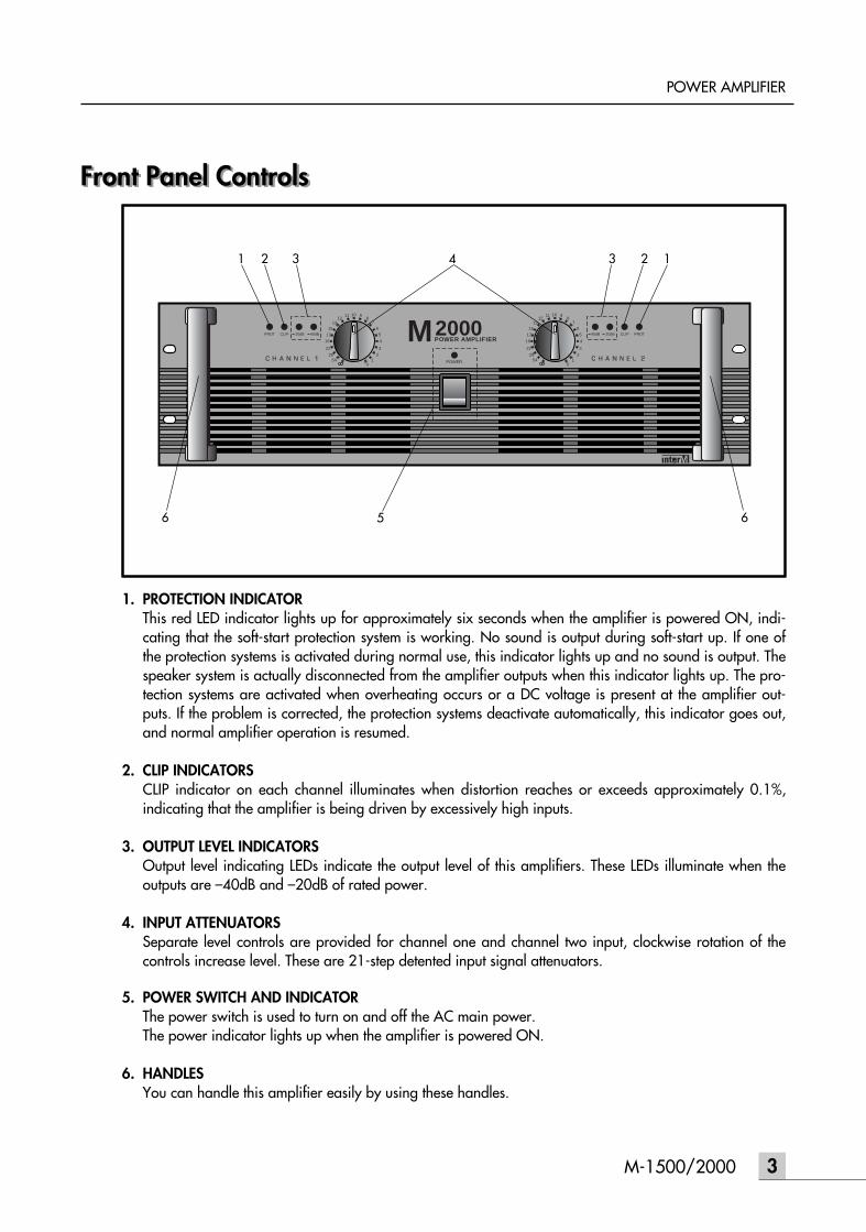
Rear Panel ControlsRear Panel Controls
1. FANSThe fans should be kept free of all obstructions and be accessible to cool fresh air when possible. It isimportant that the fans be used in a dust free environment.
2. CIRCUIT BREAKERWhen the circuit breaker is cut, push to reset again. In case of occuring trouble to the set by means ofoverload or error, circuit breaker will protect the set from trouble by breaking AC power source.
3. OUTPUT TERMINALSOutput terminals are dual five-way binding posts and speaker connectors. Do not parallel the two out-puts of each channel by connecting them (together, or parallel them) with any other amplifier output.* When speakers are connected through speaker, please make sure correct connection of each pin, andrefer speaker pin number.
- STEREO MODE - BRIDGED MODE
The minimum impedance for the connected speaker system is specified in “Speaker Impedance” on page 6.
PUSH TO RESET20A / 250V
(4Ω ~ 8Ω) (4Ω ~ 8Ω)
BRIDGED (8Ω~16Ω)
(4Ω ~ 8Ω) (4Ω ~ 8Ω)
CH 1CH 2
OUTPUT
BALANCED 0dBm
BALANCED 0dBm
CH 1CH 2
~AC INPUT230V 50Hz, 1300W
STEREOBRIDGED PARALLEL
INPUT
XLRBALANCED
•3=COLD•2=HOT•1=GND
•TIP=HOT•RING=COLD•SLEEVE=GND
TRSBALANCED
PUSH PUSH
65
1 2 43 1
1- 1+
2+ 2-
AMP OUTPUT CH1, CH2
NOT CONNECTED
(4Ω ~ 8Ω) (4Ω ~ 8Ω)
BRIDGED (8Ω~16Ω)
(4Ω ~ 8Ω) (4Ω ~ 8Ω)
CH 1CH 2
OUTPUT
1- 1+
2+ 2-MONO(BTL)CH1 OR CH2
NOT CONNECTED
(4Ω ~ 8Ω) (4Ω ~ 8Ω)
BRIDGED (8Ω~16Ω)
(4Ω ~ 8Ω) (4Ω ~ 8Ω)
CH 1CH 2
OUTPUT
5M-1500/2000
POWER AMPLIFIER
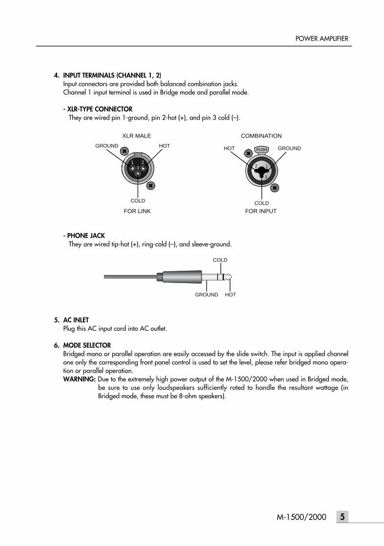
4. INPUT TERMINALS (CHANNEL 1, 2)Input connectors are provided both balanced combination jacks.Channel 1 input terminal is used in Bridge mode and parallel mode.
- XLR-TYPE CONNECTORThey are wired pin 1-ground, pin 2-hot (+), and pin 3 cold (–).
- PHONE JACKThey are wired tip-hot (+), ring-cold (–), and sleeve-ground.
5. AC INLETPlug this AC input cord into AC outlet.
6. MODE SELECTORBridged mono or parallel operation are easily accessed by the slide switch. The input is applied channelone only the corresponding front panel control is used to set the level, please refer bridged mono opera-tion or parallel operation.WARNING: Due to the extremely high power output of the M-1500/2000 when used in Bridged mode,
be sure to use only loudspeakers sufficiently rated to handle the resultant wattage (inBridged mode, these must be 8-ohm speakers).
PUSH
12
3
1 23
GROUND GROUNDHOT HOT
COLD COLD
XLR MALE COMBINATION
FOR LINK FOR INPUT
GROUND HOT
COLD

6 M-1500/2000
POWER AMPLIFIER
Protection CircuitryProtection CircuitryAs noted in the “Guided Tour” section of this manual, the M-1500/2000 front-panel Protection LED indi-cates the activity of the relay speaker connection circuitry. When the Protection LED is lit, this circuitry isactive, and all connected speakers are muted (provided with 0 volts DC), thus protecting them and prevent-ing any audible “thump” from occurring.
The following conditions will cause the Protection LED to go on:
- INITIAL POWER-UPFor approximately five seconds after initial power-up, the protection circuitry is activated and the speak-er output is muted. If everything is operating normally, you will hear an audible click at the conclusion ofthis brief period, as the protection circuitry is deactivated and the M-1500/2000 begins delivering sig-nal to connected speakers (at which point you’ll hear a click). It is normal for the Protection LED to fadegradually after the amplifier is powered off.WARNING: If the Protection LED fails to go out (and you fail to hear the accompanying audible click)
approximately five seconds after power-up, turn the M-1500/2000 off immediately andcheck all external devices and wiring for possible shorts or other defects.
- OVERHEATINGA temperature sensing device in the M-1500/2000 will cause the protection circuitry to be activated(and the Protection LED to go on) whenever the operating temperature of the unit rises above a safe lev-el. To guard against this problem, make sure the M-1500/2000 receives adequate ventilation on allsides and that both the front and rear panels are unobstructed.
- SEVERE OVERCURRENT CONDITIONSThis occurs whenever the signal being input to the M-1500/2000 rises to a level above 20% THD (TotalHarmonic Distortion).
- SHORTED SPEAKER CABLESThis will occur if, due to faulty wiring, the hot and ground signals being output by the M-1500/2000short one another.
- OUTPUT IMPEDANCE DROPS BELOW 2 OHMSThis can occur if the M-1500/2000 is connected to inappropriate speaker systems (see the “Setting Upand Using Your M-1500/2000” section on page 5 in this manual for more information).
- DC VOLTAGE DETECTED AT SPEAKER OUTPUTThe most likely cause of this is an internal failure.
In general, any time the Protection LED lights up (other than during the approximately five seconds followinginitial power-up), there is reason to be concerned. If this occurs, turn the M-1500/2000 off immediatelyand carefully check all wiring and external devices in order to locate and correct the condition that causedthe LED to light up in the first place.

7M-1500/2000
POWER AMPLIFIER
Bridged and Parallel ModesBridged and Parallel ModesThe M-1500/2000 provides a rear-panel switch that allows it to be used in either a Bridged or Parallelmode. When this switch is placed in the “STEREO” (center) position, the M-1500/2000 functions as a truestereo amplifier, where both of the two independent amplifier channels (Channel 1 and Channel 2) canreceive different input signals and produce independent output signals.However, when the switch is placed in the “BRIDGED” (left) position, the Channel 1 inputs signal is routed toboth power amplifiers bridged together, producing a single output signal with a true 1500 watt output intoa single 8 ohm channel (in the case of the M-1500) or a true 2000 watt output into a single 8 ohm channel(in the case of the M-2000).
WARNING: Bridged mode is to be used only when the M-1500/2000 is connected to an 8Ω speakerload. Use of Bridged mode with speaker loads of 4Ωs or less can result in severe damage tothe unit due to excessive heat and current limiting and will void your warranty!
The illustration belows shows how this works. In Bridged mode, the polarity (phase) of the Channel 2 outputsignal is reversed relative to that of the Channel 1 output signal. Both channels then process the same inputsignal, with the speaker load connected so that power is derived from both channels. The effective voltageswing seen by the load is thus doubled, so that the power output is doubled.
When using the M-1500/2000 in Bridged mode, be sure to connected your loudspeaker as shown in theillustration on page 9 (and as silkscreened on the rear panel), with the red (+) terminal of the Channel 2output connected to the negative input of the speaker and the red (+) terminal of the Channel 1 output con-nected to the positive input of the speaker. Do not use the black ground (–) output terminal of either channel(the speaker load must “float” away from the amplifier chassis).
When the rear panel switch is placed in the right “PARALLEL” position, the M-1500/2000 operates in aunique Parallel mode. In this mode, only the signal present at the Channel 1 input is used (and only theChannel 1 input control is functional). This signal is then routed to both the Channel 1 and Channel 2 poweramplifiers, thus producing a dual mono output, with 750 watts per channel into 4 ohms (in the case of theM-1500) or 1000 watts per channel into 4 ohms (in the case of the M-2000).
See pages 8 in this manual for interconnection diagrams when using M-1500/2000 in Bridged or Parallelmodes.
Bridged Mode
INPUT
CHANNEL1(+) OUTPUT
CHANNEL2(+) OUTPUT
8 M-1500/2000
POWER AMPLIFIER
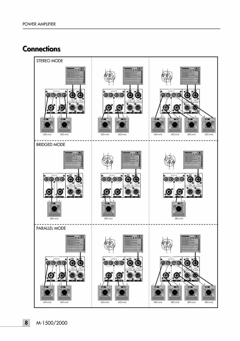
ConnectionsConnectionsSTEREO MODE
BRIDGED MODE
PARALLEL MODE

9M-1500/2000
POWER AMPLIFIER
Link ConnectorsThe illustration belows shows how multiple amplifiers can be interconnected using the M-1500/2000 linkconnectors.
Speaker Impedance
Link ConnectorsThe illustration belows shows how multiple amplifiers can be interconnected using the M-1500/2000 linkconnectors.
Speaker ImpedanceM-1500/2000 series amplifier has three operating modes: Stereo, Bridged and Parallel and allows you toconnect multiple speaker systems in parallel. Therefore, the minimum speaker impedance various depend-ing on the combination of these speakers. Be sure that the speaker impedance falls below the specifiedimpedance.The 8 page show the examples of connection is Stereo mode and Bridged mode, and speaker systems con-nected in parallel in Stereo mode, and the respective minimum impedance.
PUSH TO RESET20A / 250V
(4Ω ~ 8Ω) (4Ω ~ 8Ω)
BRIDGED (8Ω~16Ω)
(4Ω ~ 8Ω) (4Ω ~ 8Ω)
CH 1CH 2
OUTPUT
BALANCED 0dBm
BALANCED 0dBm
CH 1CH 2
~AC INPUT230V 50Hz, 1300W
STEREOBRIDGED PARALLEL
INPUT
XLRBALANCED
•3=COLD•2=HOT•1=GND
•TIP=HOT•RING=COLD•SLEEVE=GND
TRSBALANCED
PUSH PUSH
PUSH TO RESET20A / 250V
(4Ω ~ 8Ω) (4Ω ~ 8Ω)
BRIDGED (8Ω~16Ω)
(4Ω ~ 8Ω) (4Ω ~ 8Ω)
CH 1CH 2
OUTPUT
BALANCED 0dBm
BALANCED 0dBm
CH 1CH 2
~AC INPUT230V 50Hz, 1300W
STEREOBRIDGED PARALLEL
INPUT
XLRBALANCED
•3=COLD•2=HOT•1=GND
•TIP=HOT•RING=COLD•SLEEVE=GND
TRSBALANCED
PUSH PUSH
TO ADDITIONAL AMPLIFIERS

Caution for Speaker ConnectionCaution for Speaker Connection1. Turn off the POWER switch.
2. After removing approx. 10mm of insulation from the ends of the speaker cables, pass the bare ends ofthe speaker wires through the holes in the corresponding speaker terminals and tighten the terminals tosecurely clamp the wires.Refer to page 8 for speaker porality.
At this time make sure that the bare ends of the speaker cables do not extend from the terminals in sucha way that they touch the chassis.
• SPEAKER FUSEThe output capacity of your amplifier is very high: 1000W+1000W (4Ω) in stereo and 2000W (8Ω) inmonaural on the M-2000: 750W+750W (4Ω) in stereo and 1500W (8Ω) in monaural on the M-1500.Be sure to use a speaker system that has sufficient input capacity.If the input capacity of your speaker system is lower than the rated output of the power amplifier, youcan protect your speakers by connecting a fuse serially between the speaker and amplifier as shownbelow.
10 M-1500/2000
POWER AMPLIFIER
10mm
Wire should nottouch the chassis
POWER AMPLIFIER
SPEAKER SYSTEM
FUSE

11M-1500/2000
POWER AMPLIFIER
Use the following formula to determine the fuse capacity according to the speaker’s input capacity.
Po = I 2R I =
P0 [W]: Speaker’s continuous input capacity (noise or RMS)R [Ω] : Speaker’s nominal impedanceI [A] : Required fuse capacity
ex.) Speaker’s continuous input capacity: 100WSpeaker’s impedance: 8Ω
I = = 3.5
In this example, the required fuse capacity is calculated as 3.5 [A].
- SPEAKER CABLEIf you use a long speaker cable, use as thick a cable as possible to prevent deterioration of the dampingfactor or power loss inside the cable. Even the thickest cable can be used for the speaker terminal of thisunit.
Portable Rack Mounting
Use the following formula to determine the fuse capacity according to the speaker’s input capacity.
Po = I 2R I =
P0 [W]: Speaker’s continuous input capacity (noise or RMS)R [Ω] : Speaker’s nominal impedanceI [A] : Required fuse capacity
ex.) Speaker’s continuous input capacity: 100WSpeaker’s impedance: 8Ω
I = = 3.5
In this example, the required fuse capacity is calculated as 3.5 [A].
- SPEAKER CABLEIf you use a long speaker cable, use as thick a cable as possible to prevent deterioration of the dampingfactor or power loss inside the cable. Even the thickest cable can be used for the speaker terminal of thisunit.
Portable Rack MountingThe amplifier intakes cool air through the front panel and exhausts warm air out the rear panel. Whenmounting amplifiers in a portable rack, make sure the rear panel is completely open for ventilation.
PoR
1008
FAN
Air Intake
Air ExhaustFront
(Side View)
(Rear View)Completely Open
PUSH TO RESET20A / 250V
(4Ω ~ 8Ω) (4Ω ~ 8Ω)
BRIDGED (8Ω~16Ω)
(4Ω ~ 8Ω) (4Ω ~ 8Ω)
CH 1CH 2
OUTPUT
BALANCED 0dBm
BALANCED 0dBm
CH 1CH 2
~AC 230V 50Hz, 1300W
STEREOBRIDGED PARALLEL
INPUT
XLRBALANCED
¥3=COLD¥2=HOT¥1=GND
¥TIP=HOT¥RING=COLD¥SLEEVE=GND
TRSBALANCED
PUSH PUSH
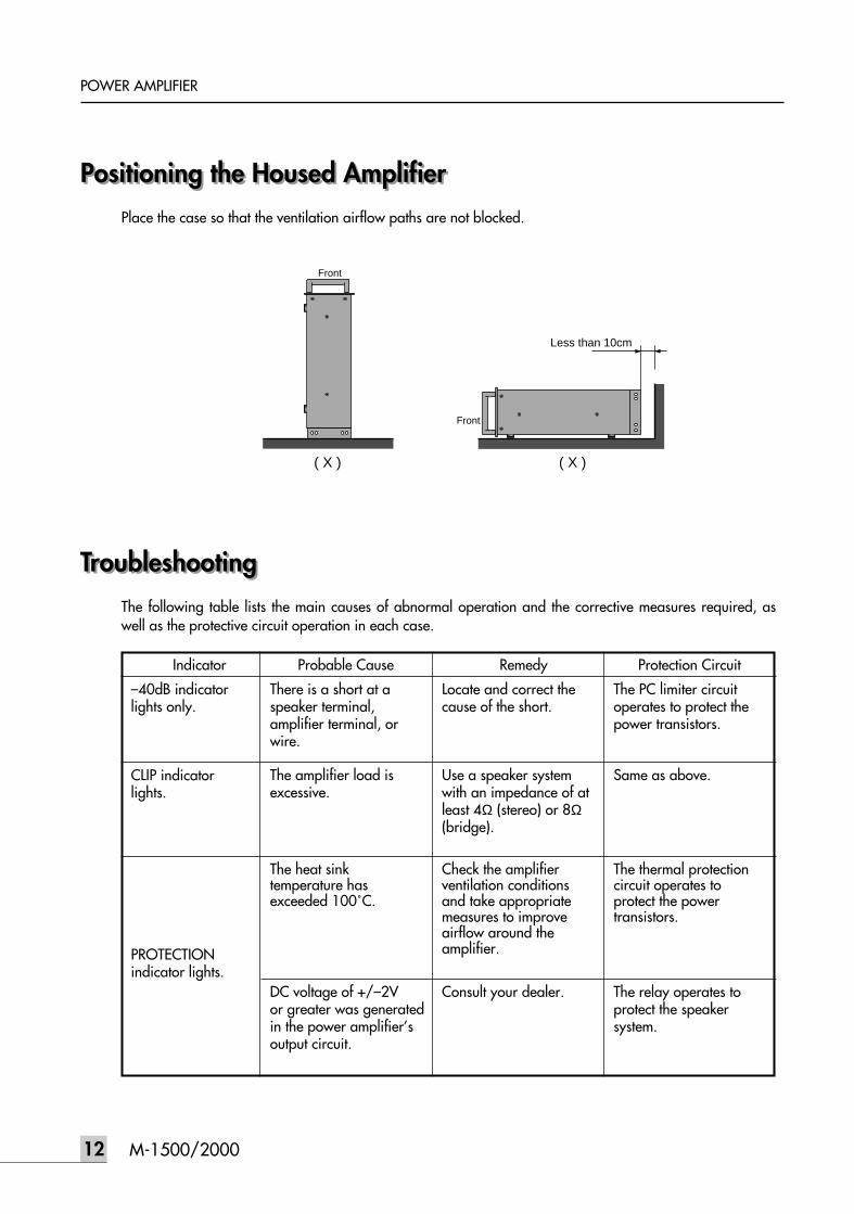
Positioning the Housed AmplifierPositioning the Housed AmplifierPlace the case so that the ventilation airflow paths are not blocked.
TroubleshootingTroubleshootingThe following table lists the main causes of abnormal operation and the corrective measures required, aswell as the protective circuit operation in each case.
Front
Front
Less than 10cm
( X ) ( X )
12 M-1500/2000
POWER AMPLIFIER
Indicator Probable Cause Remedy Protection Circuit
CLIP indicatorlights.
–40dB indicatorlights only.
There is a short at aspeaker terminal,amplifier terminal, orwire.
The amplifier load isexcessive.
DC voltage of +/–2Vor greater was generatedin the power amplifier’soutput circuit.
Consult your dealer. The relay operates toprotect the speakersystem.
The heat sinktemperature hasexceeded 100˚C.
Locate and correct thecause of the short.
Use a speaker systemwith an impedance of atleast 4Ω (stereo) or 8Ω(bridge).
Check the amplifierventilation conditionsand take appropriatemeasures to improveairflow around theamplifier.
The PC limiter circuitoperates to protect thepower transistors.
Same as above.
The thermal protectioncircuit operates toprotect the powertransistors.
PROTECTIONindicator lights.
13M-1500/2000
POWER AMPLIFIER
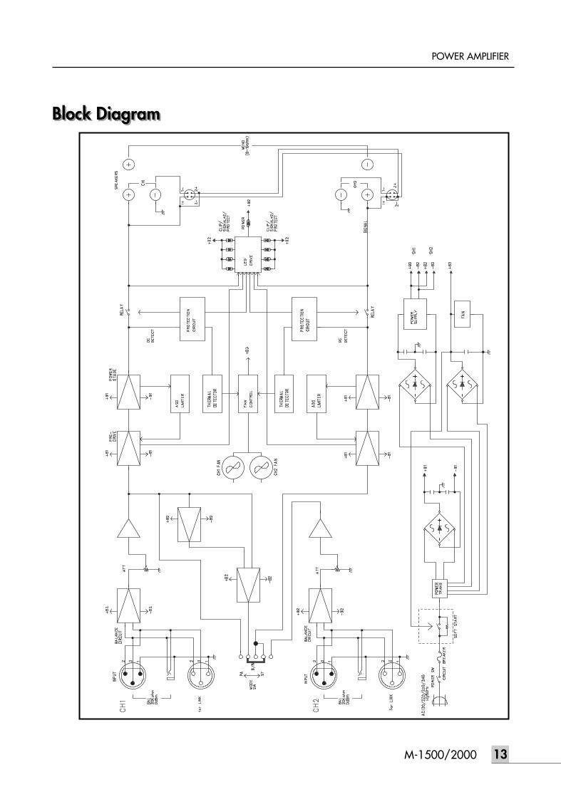
Block DiagramBlock Diagram

SpecificationsSpecifications
14 M-1500/2000
POWER AMPLIFIER
M-1500 M-2000
≥100dB
≥150
±40V/µs
0dBm
(Front) Power SW: Push up On/Push down Off Attenuator: 21-position dB calibrated
(Rear) Mode SW: Bridge=BTL/STEREO/PARALLELAC 110V–240V, 50/60Hz
1030W (1200VA) 1450W (1680VA)950W 1300W20kg 23kg
482(W) x 132(H) x 369(D) mmInput XLR-3-31 type + 1/4” Phone (balanced), XLROutput 5-Way binding posts 2, Speakon Terminal 2
Power Output Levelf=1kHz, THD+N≤0.05% (Typical)
STEREO RL=8ΩRL=4Ω
BRIDGED RL=8ΩOne Channel Driven
f=1kHz THD+N≤0.05% RL=8ΩFrequency Response RL=8Ω, P.=1WPower Bandwidth Half Power, THD+N≤0.1%
STEREO RL=8ΩTotal Harmonic Distortion (THD+N)
f=20Hz~20kHz, Half PowerSTEREO RL=8Ω
RL=4ΩBRIDGED RL=8Ω
Channel Separation Half Power RL=8Ω,f=1kHz, ATT. max. Input 600Ω shunt
Residual Noise (DIN Audio Filter)Signal-to-Noise Ratio DIN Audio,Input 600Ω ShuntDamping Factor RL=8Ω, f=1kHzSlew Rate 8Ω Full Swing STEREO
BRIDGEDSensitivity (ATT max.)
Rated Power into 4Ω 1kHzVoltage Gain (ATT max.) 4Ω 1kHzInput Impedance (ATT max.)Indicators
Protection
PC LimiterFan Circuit
Controls
Power SourcePower Consumption 120V
230V–240VWeightDimensionsConnectors
500W+500W 670W+670W750W+750W 1000W+1000W
1500W 2600W
500W 670W0dB+0.5, –1.5dB: f=DC~55kHz
10Hz~40kHz
≤ 0.05%≤ 0.07%≤ 0.07%
≥ 80dB
≤ –70dB: ATT min.
37dB 38.2dB≥ 20kΩ (Balance/Unbalance)
Power (Red)Protection (Mute) x 2 (Red)Clip x 2 (Orange)Signal x 4 (Green)Power SW ON/OFF mutingHeatsink Temp ≥ 100˚C (212˚F)RL < 2Ω-50˚C (122˚F)-60˚C (140˚F)-Low-Speed – Variable – Hi-Speed
0dB=0.775 Vrms, Half Power=1/2 Power Output Level (Rated Power)* Using reactive 2Ω speakers at high power levels may cause overheating, excessive power consumption, and shutdowns.
Please note that below 2Ω the PC limiter will work. Before using 2Ω speakers in a real application, test the system completely.
* Specifications and design subject to change without notice for improvements.

NOTE

NOTE

NOTE

MADE IN KOREA9007902810