Embed Size (px)
Citation preview
[Type the document title]
Polycom Document Title 1
Version 8.1 | June 2013 | DOC2718A
Polycom® RealPresence® Collaboration Server (RMX) 1500/2000/4000 Getting Started Guide
© 2013 Polycom, Inc. All rights reserved.
Polycom, Inc. 6001 America Center Drive San Jose CA 95002 USA
No part of this document may be reproduced or transmitted in any form or by any means, electronic or mechanical, for any purpose, without the express written permission of Polycom, Inc. Under the law, reproducing includes translating into another language or format.
As between the parties, Polycom, Inc., retains title to and ownership of all proprietary rights with respect to the software contained within its products. The software is protected by United States copyright laws and international treaty provision. Therefore, you must treat the software like any other copyrighted material (e.g., a book or sound recording).
Every effort has been made to ensure that the information in this manual is accurate. Polycom, Inc., is not responsible for printing or clerical errors. Information in this document is subject to change without notice.
Trademark Information
POLYCOM® and the names and marks associated with Polycom's products are trademarks and/or service marks of Polycom, Inc., and are registered and/or common law marks in the United States and various other countries.
All other trademarks are the property of their respective owners.
Patent Information
The accompanying product may be protected by one or more U.S. and foreign patents and/or pending patent applications held by Polycom, Inc.
End User License Agreement
Use of this software constitutes acceptance of the terms and conditions of the Polycom® RealPresence® Collaboration Server (RMX®) 1500/2000/4000 system end-user license agreements (EULA).
The EULA for your version is available on the Polycom Support page for the Polycom® RealPresence® Collaboration Server (RMX®) 1500/2000/4000 system.
For regulatory notices see the Polycom® RMX™ 1500/2000/4000 Hardware Guides.
Table of Contents
Table of Contents
System Overview . . . . . . . . . . . . . . . . . . . . . . . . . . . . . . . . . . . . . . . . . . . . . . . 1-1About the Polycom® RealPresence Collaboration Server (RMX) 1500/2000/4000 Getting Started Guide ............................................................................................................ 1-1
Prerequisites .................................................................................................................... 1-1Who Should Read This Guide? .................................................................................... 1-2How This Guide is Organized ...................................................................................... 1-2
About the Polycom® RealPresence Collaboration Server (RMX) 1500/2000/4000 System ...................................................................................................................................... 1-3RealPresence Collaboration Server Main Features ............................................................ 1-5
Conferencing Modes ...................................................................................................... 1-5AVC-based Video Session Types ................................................................................. 1-6
Dynamic Continuous Presence ............................................................................ 1-6Video Switching ...................................................................................................... 1-6Operator Conference .............................................................................................. 1-7
AVC-based Video Resolutions ..................................................................................... 1-7Resolution Configuration for AVC-based CP Conferences ............................. 1-7AVC-based Video Switching Resolutions ........................................................... 1-7
SVC-based Conferencing ............................................................................................... 1-8H.239 / People+Content ................................................................................................ 1-8Video Clarity™ (AVC-based Conferences) ................................................................ 1-8IVR-Enabled Conferencing ........................................................................................... 1-8PCM (CP AVC-based Conferences) ............................................................................. 1-9Entry Queue .................................................................................................................... 1-9Conferencing Capabilities and Options ...................................................................... 1-9
On Demand Conferencing .................................................................................... 1-9Permanent Conference ......................................................................................... 1-10Scheduled Conferencing / Reservations (AVC-based Conferencing) ......... 1-10Polycom Conferencing for Microsoft Outlook® (AVC-based Conferencing) ........................................................................................................ 1-10Connection Methods ............................................................................................ 1-10Cascading Conferences (AVC-based Conferencing) ....................................... 1-11Gateway (AVC-based Conferencing) ................................................................ 1-11Security ................................................................................................................... 1-11LAN Redundancy ................................................................................................. 1-12
Conference Management and Monitoring Features ............................................... 1-12CP AVC-based and SVC-based Conferencing ................................................. 1-12CP AVC-based Conferencing ............................................................................. 1-12
Card Configuration Modes ................................................................................................. 1-13Workstation Requirements ................................................................................................. 1-13
Microsoft Windows 7™ Security Settings ................................................................ 1-14Internet Explorer 8 Configuration .............................................................................. 1-15
First Time Installation and Configuration . . . . . . . . . . . . . . . . . . . . . . . . . . . . 2-1Preparations ............................................................................................................................ 2-1
Polycom, Inc i
RealPresence Collaboration Server (RMX) 1500/2000/4000
Gather Network Equipment and Address Information ............................................2-1IP Services ................................................................................................................2-1Management Network ...........................................................................................2-2Default IP Service (Conferencing Service) ..........................................................2-2IP Network Services Required Information ........................................................2-2ISDN/PSTN Services .............................................................................................2-4
Unpacking the RealPresence Collaboration Server (RMX) ......................................2-4Unpacking the RealPresence Collaboration Server (RMX) 1500 ......................2-4Unpacking the RealPresence Collaboration Server (RMX) 2000 ......................2-4Unpacking the RealPresence Collaboration Server (RMX) 4000 ......................2-5
Hardware Installation and Setup .........................................................................................2-6Installing the Telescopic Rail Runners on the Rack ...................................................2-7
Telescopic Rail Runners Accessory Kit ................................................................2-7Telescopic Rail Runner Assembly ........................................................................2-8
Installing the RealPresence Collaboration Server (RMX) 1500 ..............................2-12Optional. Installing the RTM ISDN 1500 Card on the RealPresence Collaboration Server (RMX) 1500 .......................................................................2-12Removing the blank cover from the rear of the RealPresence Collaboration Server (RMX) 1500 .......................................................................2-12Installing the RTM ISDN 1500 Card....................................................................2-12Mounting the RealPresence Collaboration Server (RMX) 1500 in a Rack ........................................................................................................................2-13Connecting Cables to the RealPresence Collaboration Server (RMX) 1500 .............................................................................................................2-14
Installing the RealPresence Collaboration Server (RMX) 2000 ..............................2-15Optional. Installing the RTM ISDN Card on the RealPresence Collaboration Server (RMX) 2000 .......................................................................2-15Removing the blank cover from the rear of the RealPresence Collaboration Server (RMX) 2000 .......................................................................2-15Installing the RTM ISDN 2000 Card ...................................................................2-15Mounting the RealPresence Collaboration Server (RMX) 2000 in a Rack ................................................................................................................ 2-16Connecting Cables to the RealPresence Collaboration Server (RMX) 2000 .............................................................................................................2-17
Installing the RealPresence Collaboration Server (RMX) 4000 ..............................2-19Optional. Installing the RTM ISDN Card on the RealPresence Collaboration Server (RMX) 4000 .......................................................................2-19Removing the RTM LAN Card or the blank cover from the rear of the RealPresence Collaboration Server (RMX) 4000 ...............................................2-19Installing the RTM ISDN 4000 Card....................................................................2-19Mounting the RealPresence Collaboration Server (RMX) 4000 in a Rack ........................................................................................................................ 2-20Connecting the RealPresence Collaboration Server (RMX) 4000 to the Power Sources .................................................................................................2-21Connecting Cables to the RealPresence Collaboration Server (RMX) 4000 .............................................................................................................2-23
Modifying the Factory Default Management Network Settings on the USB Memory Stick ........................................................................................................2-24
ii Polycom, Inc
Table of Contents
First Entry Power-up and Configuration .......................................................................... 2-27Procedure 1: First-time Power-up .............................................................................. 2-27Procedure 2: Product Registration ............................................................................. 2-28
Obtaining the Activation Key ............................................................................. 2-28Procedure 3: Connection to MCU .............................................................................. 2-29Procedure 4: Modifying the Default IP Service and ISDN/PSTN Network Service Settings ............................................................................................ 2-31
Fast Configuration Wizard .................................................................................. 2-31Selecting the Collaboration Server Web Client Languages .................................... 2-49
RealPresence Collaboration Server (RMX) 1500/2000/4000 Default Conferencing Settings .......................................................................................................... 2-49
Customizing the RealPresence Collaboration Server (RMX) 1500/2000/4000 Default Conferencing Settings .................................................................................... 2-52
Basic Operation . . . . . . . . . . . . . . . . . . . . . . . . . . . . . . . . . . . . . . . . . . . . . . . . . 3-1Starting the Collaboration Server Web Client .................................................................... 3-1Collaboration Server Web Client Screen Components ..................................................... 3-2
Viewing and System Functionality Permissions ............................................... 3-3Conferences List .............................................................................................................. 3-4List Pane ........................................................................................................................... 3-5RMXManagement Pane ................................................................................................. 3-5Status Bar ......................................................................................................................... 3-6
System Alerts .......................................................................................................... 3-6Participant Alerts .................................................................................................... 3-6Port Usage Gauges ................................................................................................. 3-6MCU State ................................................................................................................ 3-7
Address Book .................................................................................................................. 3-8Displaying and Hiding the Address Book .......................................................... 3-9
Conference Templates ................................................................................................... 3-9Displaying and Hiding Conference Templates .................................................. 3-9
Customizing the Main Screen ..................................................................................... 3-10Increasing and Decreasing the Text Size ........................................................... 3-11Customizing the RMX Management Pane ........................................................ 3-11
Starting a Conference ........................................................................................................... 3-12Starting an AVC CP Conference from the Conferences Pane ................................ 3-13
General Tab ........................................................................................................... 3-14Participants Tab ................................................................................................... 3-17Information Tab .................................................................................................... 3-20
Starting a Mixed CP and SVC or SVC Only Conference from the Conferences Pane ......................................................................................................... 3-22
Participants Tab ................................................................................................... 3-25Information Tab .................................................................................................... 3-25
Starting an AVC-based Reservation .......................................................................... 3-25Starting an Ongoing Conference From a Template ................................................. 3-27Starting a Meeting from Microsoft Outlook using the Polycom Conferencing Add-in to Microsoft Outlook (AVC CP Only Conferencing) ........ 3-28
Starting an Audio Meeting from a Microsoft Outlook Polycom Meeting Invitation ................................................................................................ 3-28
Connecting to a Conference ................................................................................................ 3-28
Polycom, Inc iii
RealPresence Collaboration Server (RMX) 1500/2000/4000
Direct Dial-in to the MCU ............................................................................................3-28H.323 Participants (AVC CP Only and Mixed CP and SVC Conferencing) ...............................................................................................3-29SIP Participants (AVC CP, Mixed CP and SVC and SVC Conferencing) ...............................................................................................3-29ISDN/PSTN Participants (AVC Only Conferencing) .....................................3-30
Entry Queue Access (AVC Participants) ...................................................................3-31H.323 Participants (AVC Participants) ..............................................................3-31SIP Participants (AVC Participants) ..................................................................3-32ISDN and PSTN Participants ..............................................................................3-32
Connecting to a Polycom Conference from an Outlook Meeting Invitation (AVC Only Conferencing) .........................................................................3-33Dial-out Participants (AVC CP Only and Mixed CP and SVC Conferencing) .......................................................................................................3-33
Automatic Dial Out ..............................................................................................3-33Manual Dial Out ...................................................................................................3-34
Gathering Phase (AVC Only Conferencing) .............................................................3-34Gathering Phase Guidelines ................................................................................3-35
Audio and Visual Indications (AVC CP Conferencing) .................................................3-36Site Names .....................................................................................................................3-36
Displaying and Hiding Site Names ....................................................................3-38Transparent Site Names .......................................................................................3-38Permanent Display of Site Names ......................................................................3-38Location of Site Names .........................................................................................3-39Obtaining the Display Name from the Address Book ....................................3-39
Closed Caption (AVC Only) ........................................................................................3-40Message Overlay for Text Messaging (AVC Only) ..................................................3-40Network Quality Indication ........................................................................................3-41
Network Quality Levels .......................................................................................3-41Guidelines ..............................................................................................................3-42
Audio Indications .........................................................................................................3-42Noisy Line Detection and Automatic Muting of Noisy Endpoints ...............3-42
Monitoring Ongoing Conferences ......................................................................................3-43General Monitoring ......................................................................................................3-43
Multi Selection .......................................................................................................3-44Using the Chairperson Password for Filtering .................................................3-44
Conference Level Monitoring .....................................................................................3-45Roll Call/Audible Tones During an Ongoing AVC Only Conference .........3-47Audio Only Message (AVC CP Only) ...............................................................3-48Secured Conference Monitoring (AVC CP Only) ............................................3-48Monitoring Ongoing Gateway Sessions (AVC Only) ......................................3-48
Participant Level Monitoring ......................................................................................3-49Participant Connection Monitoring (AVC and SVC-based Connections) ....3-49Video Preview (AVC-based Connection) ..........................................................3-52
Operations Performed During On Going Conferences ...................................................3-53Conference Level operations .......................................................................................3-53
Changing the Duration of a Conference ............................................................3-54
iv Polycom, Inc
Table of Contents
Adding Participants from the Address Book ................................................... 3-55Moving Participants Between Conferences (AVC-based Connection) ......... 3-55Saving an Ongoing Conference as a Template ................................................. 3-56Copy and Paste Conference ................................................................................ 3-57Copy Conference .................................................................................................. 3-57Paste Conference ................................................................................................... 3-57Paste Conference As ............................................................................................. 3-58Changing the Video Layout of a Conference (AVC-Based CP and Mixed CP and SVC Conferences) ....................................................................... 3-59Video Forcing (AVC-Based CP and Mixed CP and SVC Conferences) ........ 3-62Force Layout and Preserve Participant Call ..................................................... 3-63Enabling and Disabling Video Clarity™ (AVC-based Conferences) ............ 3-64Muting all Participants Except the Lecturer (AVC-Based CP Conferences) .................................................................................................... 3-64Sending Messages to All Conference Participants Using Message Overlay (AVC-based Conferences) .................................................................... 3-66Auto Scan (AVC-based CP Only Conferences) ................................................ 3-66Customized Polling (AVC-based CP Only Conferences) ............................... 3-67
Sending Text Messages to All Participants Using Message Overlay (AVC-based Conferences) ........................................................................................... 3-69Participant Level Operations ...................................................................................... 3-71
Copy Cut and Paste Participant ......................................................................... 3-73Copy Participant ................................................................................................... 3-73Cut Participant ...................................................................................................... 3-74Paste Participant ................................................................................................... 3-74Paste Participant As ............................................................................................. 3-75Sending Messages to Selected Participants Using Message Overlay (AVC-based Conferences) ................................................................................... 3-76
Conference Control Using DTMF Codes (AVC-based Conferences) ................... 3-77Requesting Help (AVC-based Conferences) .................................................... 3-79Request to Speak (AVC-based Conferences) .................................................... 3-79Invite Participant (AVC-based Conferences) ................................................... 3-80Invite Call Flow ..................................................................................................... 3-80Entering Additional DTMF Codes...................................................................... 3-80Error Handling....................................................................................................... 3-80Guidelines .............................................................................................................. 3-80Personal Conference Manager (PCM) (AVC-based Conferences) ................ 3-81
Guidelines ...................................................................................................................... 3-81System Flag .................................................................................................................... 3-82PCM Interface ............................................................................................................... 3-83
Initiating PCM ....................................................................................................... 3-83Remote Control Device Keys ...................................................................................... 3-85
Menu Navigation - Arrow and Zoom Keys ..................................................... 3-85PCM Main Menu - Level 1 .......................................................................................... 3-86
Click&View ........................................................................................................... 3-86Invite Participant .................................................................................................. 3-87Participants Mute/Status .................................................................................... 3-88Camera Control ..................................................................................................... 3-89
Polycom, Inc v
RealPresence Collaboration Server (RMX) 1500/2000/4000
Video Force ............................................................................................................3-90Recording ...............................................................................................................3-91
PCM Main Menu - Level 2 ...........................................................................................3-92Drop Participant ....................................................................................................3-92Terminate Conference ..........................................................................................3-93
Glossary . . . . . . . . . . . . . . . . . . . . . . . . . . . . . . . . . . . . . . . . . . . . . . . . . . . . . . . A-1Troubleshooting . . . . . . . . . . . . . . . . . . . . . . . . . . . . . . . . . . . . . . . . . . . . . . . . B-1
Collaboration Server Web Client Installation - Troubleshooting Instructions ............. B-1Procedure 1: Ending all Internet Explorer Sessions .................................................. B-2Procedure 2: Deleting the Temporary Internet Files, Collaboration Server Cookie and Collaboration Server Object ........................................................ B-2
Deleting the Temporary Internet Files ................................................................ B-3Deleting the RMX/Collaboration Server Cookie .............................................. B-5Deleting the RMX/Collaboration Server ActiveX Object ................................ B-6
Procedure 3: Managing Add-ons Collisions .............................................................. B-7Procedure 4: Browser Hosting Controls (Optional) .................................................. B-8
vi Polycom, Inc
1
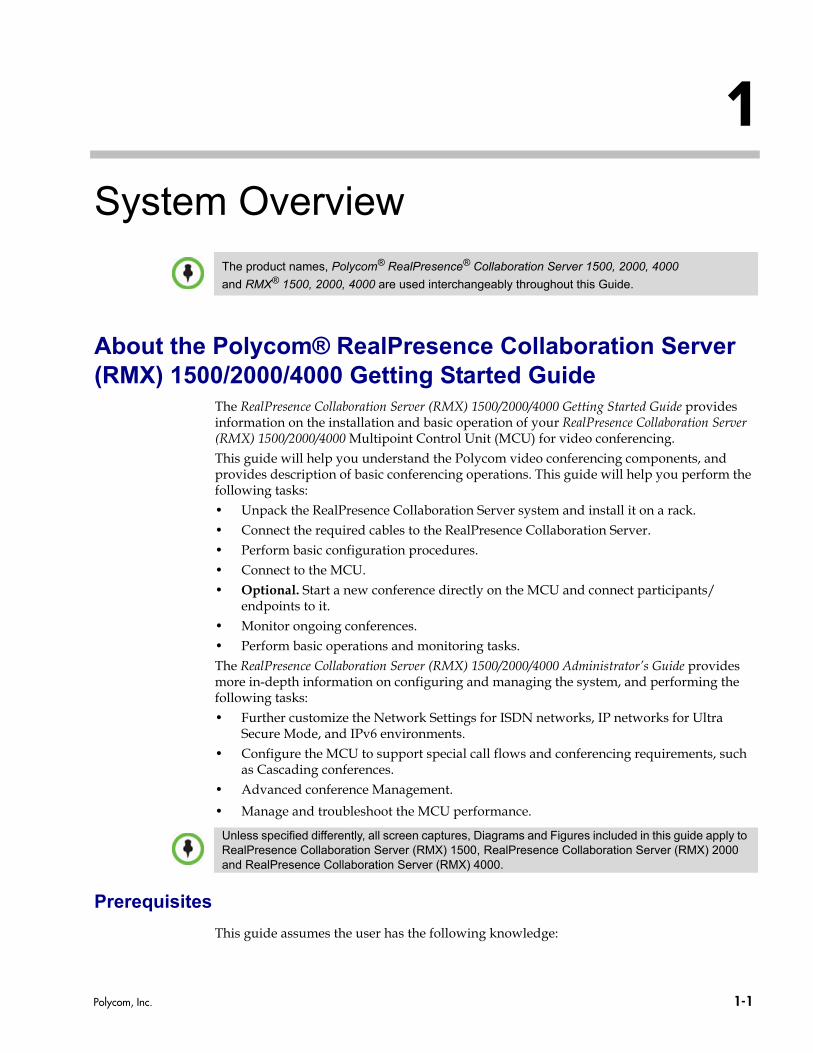
System OverviewAbout the Polycom® RealPresence Collaboration Server (RMX) 1500/2000/4000 Getting Started Guide
The RealPresence Collaboration Server (RMX) 1500/2000/4000 Getting Started Guide provides information on the installation and basic operation of your RealPresence Collaboration Server (RMX) 1500/2000/4000 Multipoint Control Unit (MCU) for video conferencing. This guide will help you understand the Polycom video conferencing components, and provides description of basic conferencing operations. This guide will help you perform the following tasks:• Unpack the RealPresence Collaboration Server system and install it on a rack.• Connect the required cables to the RealPresence Collaboration Server.• Perform basic configuration procedures.• Connect to the MCU.• Optional. Start a new conference directly on the MCU and connect participants/
endpoints to it.• Monitor ongoing conferences.• Perform basic operations and monitoring tasks.The RealPresence Collaboration Server (RMX) 1500/2000/4000 Administrator’s Guide provides more in-depth information on configuring and managing the system, and performing the following tasks:• Further customize the Network Settings for ISDN networks, IP networks for Ultra
Secure Mode, and IPv6 environments.• Configure the MCU to support special call flows and conferencing requirements, such
as Cascading conferences.• Advanced conference Management.
• Manage and troubleshoot the MCU performance.
Prerequisites
This guide assumes the user has the following knowledge:
The product names, Polycom® RealPresence® Collaboration Server 1500, 2000, 4000
and RMX® 1500, 2000, 4000 are used interchangeably throughout this Guide.
Unless specified differently, all screen captures, Diagrams and Figures included in this guide apply to RealPresence Collaboration Server (RMX) 1500, RealPresence Collaboration Server (RMX) 2000 and RealPresence Collaboration Server (RMX) 4000.
Polycom, Inc. 1-1
Polycom® RealPresence Collaboration Server (RMX) 1500/2000/4000 Getting Started Guide
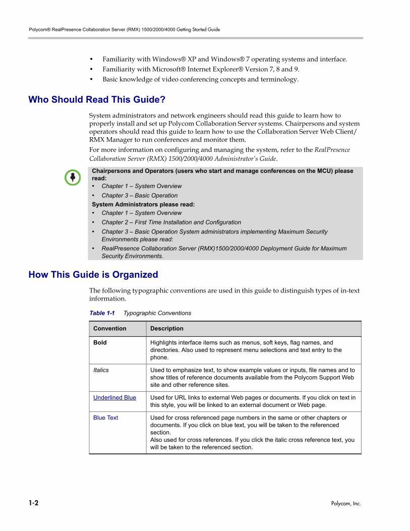
• Familiarity with Windows® XP and Windows® 7 operating systems and interface.• Familiarity with Microsoft® Internet Explorer® Version 7, 8 and 9.• Basic knowledge of video conferencing concepts and terminology.
Who Should Read This Guide?
System administrators and network engineers should read this guide to learn how to properly install and set up Polycom Collaboration Server systems. Chairpersons and system operators should read this guide to learn how to use the Collaboration Server Web Client/RMX Manager to run conferences and monitor them.For more information on configuring and managing the system, refer to the RealPresence Collaboration Server (RMX) 1500/2000/4000 Administrator’s Guide.
How This Guide is Organized
The following typographic conventions are used in this guide to distinguish types of in-text information.
Chairpersons and Operators (users who start and manage conferences on the MCU) please read:• Chapter 1 – System Overview
• Chapter 3 – Basic Operation
System Administrators please read:
• Chapter 1 – System Overview
• Chapter 2 – First Time Installation and Configuration
• Chapter 3 – Basic Operation System administrators implementing Maximum Security Environments please read:
• RealPresence Collaboration Server (RMX)1500/2000/4000 Deployment Guide for Maximum Security Environments.
Table 1-1 Typographic Conventions
Convention Description
Bold Highlights interface items such as menus, soft keys, flag names, and directories. Also used to represent menu selections and text entry to the phone.
Italics Used to emphasize text, to show example values or inputs, file names and to show titles of reference documents available from the Polycom Support Web site and other reference sites.
Underlined Blue Used for URL links to external Web pages or documents. If you click on text in this style, you will be linked to an external document or Web page.
Blue Text Used for cross referenced page numbers in the same or other chapters or documents. If you click on blue text, you will be taken to the referenced section.Also used for cross references. If you click the italic cross reference text, you will be taken to the referenced section.
1-2 Polycom, Inc.
Chapter 1-System Overview
Po
About the Polycom® RealPresence Collaboration Server (RMX) 1500/2000/4000 System
The Polycom® RealPresence Collaboration Server (RMX) 1500/2000/4000 is a high performance, scalable, IP-network (H.323 and SIP) and ISDN/PSTN MCU that provides feature-rich and easy-to-use multipoint voice and video conferencing.It meets International Telecommunication Union - Telecommunication Standardization Sector, (ITU-T, formerly CCITT) standards for multipoint multimedia bridging devices, and meets ETSI standards for telecommunication products. In addition, it has been designed in compliance with IETF (Internet Engineering Task Force).The MCU can be used as a standalone device to run voice and video conferences or it can be used as part of a solution provided by Polycom. This solution may include the following components:• Polycom® RSS™ 4000 - provides one-touch recording and secure playback on
telepresence and video conferencing systems, tablets and smartphones, or from your Web browser.
• Polycom® Distributed Media Application™ (DMA™) - provides call control and MCU virtualization with carrier-grade redundancy, resiliency and scalability.
• Polycom Real Presence Resource Manager - centrally manages, monitors and delivers Cloud based Video as a Service (VaaS) and enterprise video collaboration.
• Polycom® RealPresence® Access Director™ (RPAD) - removes communication barriers and enables internal and external teams to collaborate more easily and effectively over video.
<variable name> Indicates a variable for which you must enter information specific to your installation, endpoint, or network. For example, when you see <IP address>, enter the IP address of the described device.
> Indicates that you need to select an item from a menu. For example, Administration > System Information indicates that you need to select System Information from the Administration menu.
Table 1-1 Typographic Conventions (Continued)
Convention Description
lycom, Inc. 1-3
Polycom® RealPresence Collaboration Server (RMX) 1500/2000/4000 Getting Started Guide
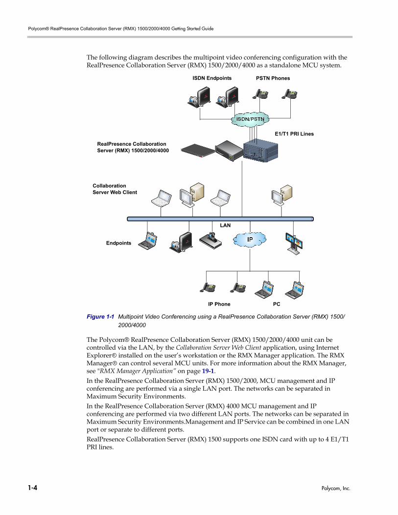
The following diagram describes the multipoint video conferencing configuration with the RealPresence Collaboration Server (RMX) 1500/2000/4000 as a standalone MCU system.
Figure 1-1 Multipoint Video Conferencing using a RealPresence Collaboration Server (RMX) 1500/
2000/4000
The Polycom® RealPresence Collaboration Server (RMX) 1500/2000/4000 unit can be controlled via the LAN, by the Collaboration Server Web Client application, using Internet Explorer installed on the user’s workstation or the RMX Manager application. The RMX Manager can control several MCU units. For more information about the RMX Manager, see "RMX Manager Application” on page 19-1.In the RealPresence Collaboration Server (RMX) 1500/2000, MCU management and IP conferencing are performed via a single LAN port. The networks can be separated in Maximum Security Environments.In the RealPresence Collaboration Server (RMX) 4000 MCU management and IP conferencing are performed via two different LAN ports. The networks can be separated in Maximum Security Environments.Management and IP Service can be combined in one LAN port or separate to different ports.RealPresence Collaboration Server (RMX) 1500 supports one ISDN card with up to 4 E1/T1 PRI lines.
PSTN Phones
Collaboration Server Web Client
PCIP Phone
Endpoints
E1/T1 PRI Lines
RealPresence Collaboration Server (RMX) 1500/2000/4000
ISDN Endpoints
LAN
R
R
1-4 Polycom, Inc.
Chapter 1-System Overview
RealPresence Collaboration Server (RMX) 2000 and RealPresence Collaboration Server (RMX) 4000 support a maximum of two RTM ISDN cards, each providing connection for up to either 7 E1 or 9 T1 PRI lines.On RealPresence Collaboration Server (RMX) 1500/2000/4000, E1 and T1 connections cannot be used simultaneously.
RealPresence Collaboration Server Main Features
Conferencing Modes
The MCU system offers the following Conferencing Modes:• Media Relay - SVC Conferencing• Mixed CP and SVC Conferencing• CP Transcoding - AVC-based ConferencingA transcoded CP (Continuous Presence) conference is also described as an AVC (Advanced Video Coding) conference. It supports the standard video protocols. In this mode, video is received from all the endpoints using different line rates, different protocols (SIP, H.323, PSTN and ISDN) and video parameters:• Video protocols: H.261, H.263, H.264 Base and High profile and RTV• Video Resolutions: from QCIF, CIF and up to 60• Frame rates up to 60fpsAll endpoints that do not support the H.264 SVC protocol such as H.263, and H.264, or RTV, are considered AVC endpoints.The MCU process the received video, transcodes it and send the resulting video streams to the endpoints. The video processing that is required differs according to the video session set for the conference, with all the processing performed by the MCU. For more details, see RealPresence Collaboration Server (RMX) 1500/2000/4000 Administrator’s Guide, "AVC Conferencing - Video Session Types” on page 2-4.Media Relay - SVC ConferencingMedia Relay SVC Conferencing is based on the Scalable Video Coding (SVC) video protocol and SAC Polycom's proprietary Scalable Audio Coding protocol. It offers high resolution video conferencing with low end-to-end latency, improved Error Resiliency and higher system capacities.The Polycom multipoint media server, serves as an integrated media relay engine that provides media streams for displaying conferences at low latency video experience in video conferences. For more details, see RealPresence Collaboration Server (RMX) 1500/2000/4000 Administrator’s Guide, "SVC-based Conferencing” on page 2-12.
Mixed CP and SVC ConferencingThis type of conference enables participants with SVC-enabled endpoints and AVC endpoints to participate in the same conference.Each endpoint connects according to its capabilities. The MCU processes the AVC video streams and converts them into SVC video Streams and relays them to the SVC participants that constructs the video layout on the endpoint. In the same way, the MCU processes the video streams received from the SVC participants, converts them into AVC video and then transcodes all the video streams to compose the video layout that is sent to the AVC endpoints.
Polycom, Inc. 1-5
Polycom® RealPresence Collaboration Server (RMX) 1500/2000/4000 Getting Started Guide
AVC-based Video Session Types
All endpoints have AVC capabilities and can connect to AVC conferences running on the MCU. AVC-based endpoints can connect using different signaling protocols and different video protocols. Based on the video processing required during the conference, the Collaboration Server offers two Video Session Types for AVC-based conferencing: • Continuous Presence• Video SwitchingThe video session type determines the video display options (full screen or split screen with all participants viewed simultaneously) and the method in which the video is processed by the MCU (with or without using the MCU’s video resources).
Dynamic Continuous Presence
The dynamic Continuous Presence (CP) capability of the Collaboration Server system enables viewing flexibility by offering multiple viewing options and window layouts for video conferencing. By default every conference, Entry Queue and Meeting Room has the ability to declare the maximum CP resolution as defined for the system. This includes conferences launched by the Collaboration Server Web Client and conferences started via the API.For more details, see RealPresence Collaboration Server (RMX) 1500/2000/4000 Administrator’s Guide, "Continuous Presence (CP) Conferencing” on page 2-4.
Video Layouts in CPA selection of layouts are available to accommodate different numbers of participants and conference settings. The VUI annex to the H.264 protocol for endpoints that transmit wide video format instead of 4CIF resolution is also supported.
Telepresence ModeTPX (Telepresence) and RPX (RealPresence) room systems are configured with high definition cameras and displays that are set up to ensure that all participants share a sense of being in the same room.The RealPresence Collaboration Server enables Telepresence Rooms to connect to conferences where point-to-point connections cannot be used. Additional video layouts have been created to give Telepresence operators more video layout options when configuring TPX room systems. These additional video layout options are available for selection when Telepresence is selected in the conference profile.
Multiple Switching ModesIf the number of participants is higher than the number of video windows in the selected layout, switching between video participants can be performed in one of these modes:• Voice activation (default mode)• The Collaboration Server user forces participants to selected video window • Lecture Mode - The lecturer is viewed in full screen by all conference participants, while
the audience is “time-switched” in the speaker’s view• Presentation Mode - When the speaker’s presentation extends beyond a predefined time,
he/she becomes the current lecturer and the conference switches to Lecture Mode
Video Switching
In Video Switching (VSW) mode all participants see the same video picture (full screen). Only one CIF video resource is used for each connection.
1-6 Polycom, Inc.
Chapter 1-System Overview
In VSW conferences:— All endpoints must connect to the conference at the same Line Rate. Line rates range
from 192Kbps to 6Mb. The Collaboration Server will always connect participants at the highest possible video quality that is supported by the conference Line Rate.
— All endpoints must connect to the conference at the same video protocol and resolution. Video Protocol and Resolution ranges from H.261 CIF to H.264 1080p60.
— Compliant endpoints must connect to conferences at the conference line rate and resolutions. Endpoints that do not meet the conference requirements connect as Secondary (Audio Only) if there are resources defined for Voice connection or they will disconnect from the conference if there are not such resources.
For more details, see RealPresence Collaboration Server (RMX) 1500/2000/4000 Administrator’s Guide, "Video Switching (VSW) Conferencing” on page 2-6.
Operator Conference
In Continuous Presence conferencing, a special conference that enables the MCU user, acting as an operator, to assist participants without disturbing ongoing conferences and without being heard by other conference participants. The operator can move a participant from an Entry Queue or ongoing conference to a private, one-on-one conversation in the Operator conference. For more details, see RealPresence Collaboration Server (RMX) 1500/2000/4000 Administrator’s Guide, "Operator Conferences” on page 10-1.
AVC-based Video Resolutions
Resolution Configuration for AVC-based CP Conferences
The Resolution Configuration dialog box enables the Collaboration Server administrators to modify the video resolution decision matrix, effectively creating their own decision matrix. The minimum threshold line rates at which endpoints are connected at the various video resolutions can be optimized by adjusting the resolution sliders.For more information see the RealPresence Collaboration Server (RMX) 1500/2000/4000 Administrator’s Guide, "Video Resolutions in AVC-based CP Conferencing” on page 3-1.
AVC-based Video Switching Resolutions
In Video Switching (VSW) conferences, participants must connect at the conference line rate, video protocol and resolution. Endpoints that cannot connect using these settings will be connected using Audio only and their status will appear as Secondary (no video).The video quality for the conference is determined by the conference video protocol and resolution and it should be set based on the endpoint with the lowest capabilities that will be connected to the conference. • Available resolutions in Video Switching mode are: H.261 CIF, H.263 CIF, H.264 CIF,
H.264 SD 30, H.264 720p 30, H.264 720p 60 and H.264 1080p60.For more details, see RealPresence Collaboration Server (RMX) 1500/2000/4000 Administrator’s Guide, "Video Switching (VSW) Conferencing” on page 2-6.
Polycom, Inc. 1-7
Polycom® RealPresence Collaboration Server (RMX) 1500/2000/4000 Getting Started Guide
SVC-based Conferencing
In the Scalable Video Codec (SVC)-based conference, each SVC-enabled endpoint transmits multiple bit streams, to the Polycom® RealPresence® Collaboration Server. Simulcasting enables each endpoint to transmit at different resolutions and frame rates such as 720p at 30fps, 15fps, and 7.5fps, 360p at 15fps and 7.5fps, and 180p at 7.5fps. Using the SVC video protocol, SVC conferences relays the received video streams to the SVC-enabled endpoints at different resolutions, frame rates and line rates according to the endpoint’s display capabilities and layout configurations without sending the entire video layout to the endpoints. For more details, see RealPresence Collaboration Server (RMX) 1500/2000/4000 Administrator’s Guide, "SVC-based Conferencing” on page 2-12.
H.239 / People+Content
The H.239 protocol allows compliant endpoints to share content. By default, all Conferences, Entry Queues, and Meeting Rooms launched on the Collaboration Server have H.239 capability. This protocol is also supported in MIH Cascading conferences.Conferences can include a mix of endpoints that support H.239 or People+Content. People+Content is Polycom’s proprietary equivalent of H.239.For more details, see RealPresence Collaboration Server (RMX) 1500/2000/4000 Administrator’s Guide, "Content Sharing” on page 3-2.
Video Clarity™ (AVC-based Conferences)
The Video Clarity feature applies video enhancing algorithms to incoming video streams of resolutions up to and including SD. Clearer images with sharper edges and higher contrast are sent back to all endpoints at the highest possible resolution supported by each endpoint.All layouts, including 1x1, are supported. Video Clarity can only be enabled for Continuous Presence conferences in MPM+ and MPMx Modes.
IVR-Enabled Conferencing
Interactive Voice Response (IVR) is a software module that automates the connection process and lets participants perform various operations during ongoing conferences. The participants use their endpoints’ keypads, remote controls and touch control devices to interact with the conference’s menu-driven scripts using DTMF codes.Operations that can be performed by participants or chairpersons during a conference include:• Initiate Polycom’s Click&View™ application to change the local screen layout (AVC-
based conferencing).• Mute or unmute the participant’s audio channel.• Adjust the participant’s broadcasting and listening audio volume (AVC-based
conferencing).• Play the Help menu.• Mute or unmute undefined dial-in participants upon their connection to the conference.
1-8 Polycom, Inc.

Chapter 1-System Overview
• Request a Roll Call and stop the Roll Call names review (AVC-based conferencing)• Secure and unsecure a conference.• Request individual and conference assistance (CP conferences). • Manually terminate the conference.For more details, see RealPresence Collaboration Server (RMX) 1500/2000/4000 Administrator’s Guide, "IVR Services” on page 17-1.
PCM (CP AVC-based Conferences)
The Personal Conference Manager (PCM) interface enables the conference chairperson to control various conference features using his/her endpoint’s remote control device.The following conference operations can be performed:• Initiate Polycom’s Click&View™ application to change the local screen layout.• Invite participants to connect to the conference.• View and control the audio and video of each connected endpoint.• Camera Control - control the camera of a remote endpoint using (FECC).• Control the camera of a connected endpoint.• Video Force a specific participant to a specific window of the video layout.• Initiate and control recording of the conference.• Disconnect a participant.• Terminate the conference.
Entry Queue
An Entry Queue is a special routing lobby for video and audio participants. After dialing the Entry Queue ID or dial-in number (ISDN/PSTN), voice prompts from an IVR service are used to connect the participants to the appropriate conference. This service can also be used (if required) to verify the participant’s right to start an Ad Hoc conference or to join an ongoing conference. For more details, see RealPresence Collaboration Server (RMX) 1500/2000/4000 Administrator’s Guide, "Entry Queues” on page 7-1.
Conferencing Capabilities and Options
On Demand Conferencing
The following options are available to set up conferences:• New Conference – set up once, use once.
The conference is deleted from the MCU after it ends.• Meeting Rooms – set up once, use many times.
Meeting Rooms are saved in memory (using no resources) and can be activated as many times as needed.
• Ad Hoc Entry Queue (CP AVC Only and Mixed CP and SVC Conferencing) – no setup, a new conference can be created when an AVC participant dials in and enters a conference ID that is not being used by an existing conference or Meeting Room.
Polycom, Inc. 1-9
Polycom® RealPresence Collaboration Server (RMX) 1500/2000/4000 Getting Started Guide
• Gateway calls (AVC Only Conferencing) – from IP endpoints to other participants, using the direct dialing method, with up to 10 destination numbers contained in a single dial string.
Permanent Conference
A Permanent Conference is an ongoing conference with no predetermined End Time, continuing until it is terminated by an administrator, operator or chairperson. For more details, see RealPresence Collaboration Server (RMX) 1500/2000/4000 Administrator’s Guide, "]” on page 3-81.
Scheduled Conferencing / Reservations (AVC-based Conferencing)
Reservations provide calendar-based scheduling of single or recurring conferences. These conferences can be launched immediately or become ongoing, at a specified time on a specified date. For more details, see RealPresence Collaboration Server (RMX) 1500/2000/4000 Administrator’s Guide, "Reservations” on page 9-1.
Polycom Conferencing for Microsoft Outlook® (AVC-based
Conferencing)
Polycom Conferencing for Microsoft Outlook is implemented by installing the Polycom Conferencing Add-in for Microsoft Outlook on Microsoft Outlook -mail clients. It enables meetings to be scheduled with video endpoints from within Outlook. The add-in also adds a Polycom Conference button in the Meeting tab of the Microsoft Outlook e-mail client ribbon.For more details, see RealPresence Collaboration Server (RMX) 1500/2000/4000 Administrator’s Guide, "Polycom Conferencing for Microsoft Outlook®” on page 12-1.
Connection Methods
All endpoints that do not support the H.264 SVC protocol such as H.263, H.264, or RTV, are considered AVC endpoints.
AVC-based ConnectionsIn AVC-based connection, IPv4, IPv6, ISDN and PSTN H.323 and SIP communication protocols aresupported for connection to the conference. Endpoints can connect using the following Video Protocols: H.263, H.264 Base and High Profile and RTV.• Dial-out: automatically, to pre-defined participants (line rate detection is automatic)• Dial-in:
— for participants defined in advance — for undefined participants connecting directly to a conference (IP and ISDN/
PSTN)— for undefined participants via a single dial Entry Queue (IP and ISDN/PSTN)
SVC-based ConnectionsIn SVC-based connections, IPv4 SIP communication protocol is supported for connection to the conference. Endpoints can connect using the SVC Video Protocol.• Dial-out: not supported for SVC participants in SVC Only or mixed CP and SVC
conferences
1-10 Polycom, Inc.
Chapter 1-System Overview
• Dial-in:— for participants defined in advance — for undefined participants connecting directly to a conference (SIP)
Cascading Conferences (AVC-based Conferencing)
Cascading enables administrators to connect one conference directly to one or several conferences usually running on different MCUs, depending on the topology, creating one large conference. Supported topologies are:• Basic Cascading of two MCUs.• Star Topology.• Multi Hierarchy Cascading (MIH).For more details, see RealPresence Collaboration Server (RMX) 1500/2000/4000 Administrator’s Guide, "Cascading Conferences” on page 5-1.
Gateway (AVC-based Conferencing)
Using a special Gateway Profile, the Collaboration Server can be used as a gateway that provides connectivity across different physical networks such as H.323, SIP, ISDN and PSTN. The Gateway also provides connectivity between the ISDN/PSTN endpoints and the DMA.For more details, see RealPresence Collaboration Server (RMX) 1500/2000/4000 Administrator’s Guide, "Gateway Calls” on page 19-1.
Security
• In CP conferences Media Encryption is available at conference and participant levels, based on AES 128 Media Encryption and DH 1024 Key Exchange standards.
• Secured Communication Mode (SSL/TLS).• Secured conferences via DTMF codes and limited monitoring of secured conferences.• Auditor to analyze configuration changes and unusual or malicious activities in the
Collaboration Server. • Network security can be enhanced by separation of the Signaling and Management
Networks.
• Collaboration Server Users can be disabled by the administrator, or automatically when inactive. Disabled Users can be enabled by the administrator.
• Support for SNMP versions 1, 2 and 3. • In Maximum Security Environments Ultra Secure Mode can be implemented.
In such an environment, the following attributes are implemented:— Password management:
• Strong Passwords and password re-use / history rules,• password aging rules, password change frequency and forcing password
change• Conference and Chairman Passwords• Locking out Users • Displaying the User Login record
— Controlling the User Sessions includes:• Limiting the maximum number of concurrent user sessions• Connection Timeout
Polycom, Inc. 1-11
Polycom® RealPresence Collaboration Server (RMX) 1500/2000/4000 Getting Started Guide
• User session timeout• Limiting the maximum number of users that can connect to the system• Multiple Network Services
LAN Redundancy
Enables the redundant LAN port connection to automatically replace the failed LAN port by using another physical connection and NIC (Network Interface Card) should a LAN port fail.For more details, see RealPresence Collaboration Server (RMX) 1500/2000/4000 Administrator’s Guide, "LAN Redundancy” on page 16-37.
Conference Management and Monitoring Features
The Collaboration Server Web Client and RMX Manager application provide capabilities for management and monitoring of participants and conferences, including the following:
CP AVC-based and SVC-based Conferencing
• Active display of all conferences and participants• Real-time monitoring of each participant’s connection status and properties.• Automatic termination of idle (no participants) conferences.• Automatic extension of conference Duration.• Control of listening and broadcasting audio volume for individual participants.• Easily accessed Call Detail Records (CDR) for administrator.• Active display of all system resources.• Hot Backup implements a high availability and rapid recovery solution.
CP AVC-based Conferencing
• Lecture Mode or Presentation Mode in Continuous Presence conferences.• Far End Camera Control (FECC/LSD) in video conferences.• Auto Gain Control (AGC) noise and audio volume regulation for individual participants.• Conference control via DTMF codes from participant’s endpoint or telephone.• Entry, exit and end-of-conference indications.• Media Encryption.• Option to limit the properties display of conference participants in secured conferences.• Multiple drag & drop of participants.• Closed Caption provides real-time text transcriptions or language translations of the
video conference.• Message Overlay allows messages to be sent to all or specific participants in an ongoing
conference.• PCM enables the conference chairperson to control various conference features using
his/her endpoint’s remote control device.• Video Preview allows Collaboration Server users to preview video sent from the
participants to the conference and from the conference to the participants.• Auto Redial when Endpoint Drops instructs the Collaboration Server to automatically
redial IP and SIP participants that have been abnormally disconnected from the conference.
1-12 Polycom, Inc.
Chapter 1-System Overview
• Operator Assistance & Participant Move for conferences in CP mode.
Card Configuration ModesThe media card installed in the system determines the Card Configuration Mode. The Card Configuration Mode represents different generations of the media card. Each new generation provides additional functionality, higher video resolutions and higher resource capacity. Only one Media Card type can be installed in any Collaboration Server, which sets the Card Configuration Mode for that Collaboration Server: • MPM+ Mode – Supported from Version 4.0, with MPM+ cards installed in the
RealPresence Collaboration Server (RMX) 2000 and RealPresence Collaboration Server (RMX) 4000.
• MPMx Mode – Supported from Version 7.0, with MPMx cards installed in the RealPresence Collaboration Server (RMX) 1500, RealPresence Collaboration Server (RMX) 2000 and RealPresence Collaboration Server (RMX) 4000. For features supported with MPMx cards only.
For more details, see "Card Configuration Modes” on page 1-13, "Card Configuration Modes” on page 1-4.
Workstation RequirementsThe Collaboration Server Web Client and RMX Manager applications can be installed in an environment that meets the following requirements:• Minimum Hardware – Intel® Pentium® III, 1 GHz or higher,1024 MB RAM,
500 MB free disk space.• Workstation Operating System – Microsoft® Windows® XP, Vista®, Windows® 7. • Network Card – 10/100/1000 Mbps.• Web Browser - Microsoft® Internet Explorer® Version 7, 8 and 9.• Collaboration Server Web Client and RMX Manager are optimized for display at a
resolution of 1280 x 800 pixels and a magnification of 100%.
From Version 8.0, MPM+ media cards are not supported.
.Net Framework 2.0 is required and installed automatically.If ActiveX installation is blocked please see the RealPresence Collaboration Server (RMX) 1500/2000/4000 Administrator’s Guide, "ActiveX Bypass” on page 20-75.
Collaboration Server Web Client does not support larger Windows text or font sizes. It is recommended to set the text size to 100% (default) or Normal in the Display settings in Windows Control Panel on all workstations. Otherwise, some dialog boxes might not appear properly aligned. To change the text size, select Control Panel>Display. For Windows XP, click the Appearance tab, select Normal for the Font size and click OK. For Windows 7, click the Smaller - 100% option and click OK.
When installing the Collaboration Server Web Client, Windows Explorer >Internet Options> Security Settings must be set to Medium or less.
Polycom, Inc. 1-13
Polycom® RealPresence Collaboration Server (RMX) 1500/2000/4000 Getting Started Guide
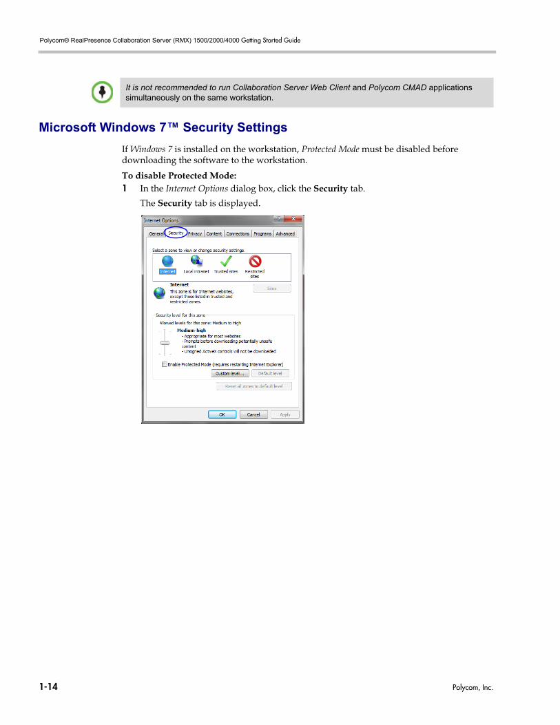
Microsoft Windows 7™ Security Settings
If Windows 7 is installed on the workstation, Protected Mode must be disabled before downloading the software to the workstation.
To disable Protected Mode:1 In the Internet Options dialog box, click the Security tab.
The Security tab is displayed.
It is not recommended to run Collaboration Server Web Client and Polycom CMAD applications simultaneously on the same workstation.
1-14 Polycom, Inc.
Chapter 1-System Overview
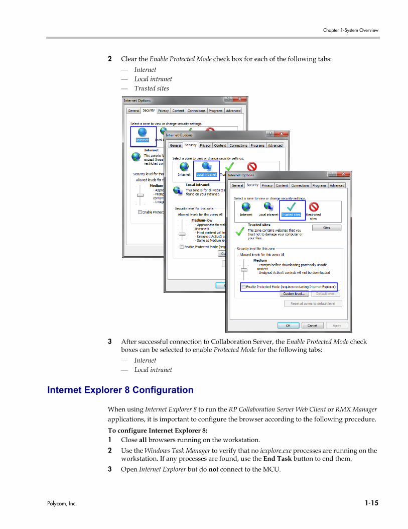
2 Clear the Enable Protected Mode check box for each of the following tabs:
— Internet— Local intranet— Trusted sites
3 After successful connection to Collaboration Server, the Enable Protected Mode check boxes can be selected to enable Protected Mode for the following tabs:
— Internet— Local intranet
Internet Explorer 8 Configuration
When using Internet Explorer 8 to run the RP Collaboration Server Web Client or RMX Manager applications, it is important to configure the browser according to the following procedure.
To configure Internet Explorer 8:1 Close all browsers running on the workstation.
2 Use the Windows Task Manager to verify that no iexplore.exe processes are running on the workstation. If any processes are found, use the End Task button to end them.
3 Open Internet Explorer but do not connect to the MCU.
Polycom, Inc. 1-15
Polycom® RealPresence Collaboration Server (RMX) 1500/2000/4000 Getting Started Guide
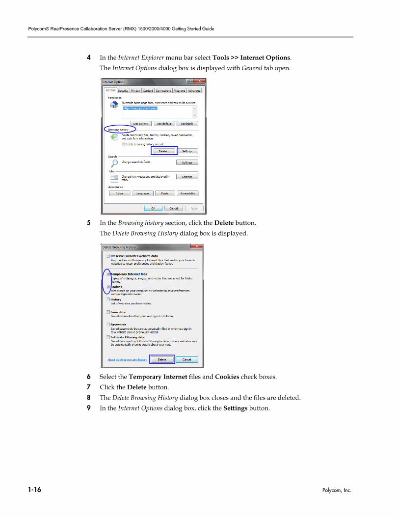
4 In the Internet Explorer menu bar select Tools >> Internet Options.
The Internet Options dialog box is displayed with General tab open.
5 In the Browsing history section, click the Delete button.
The Delete Browsing History dialog box is displayed.
6 Select the Temporary Internet files and Cookies check boxes.
7 Click the Delete button.
8 The Delete Browsing History dialog box closes and the files are deleted.
9 In the Internet Options dialog box, click the Settings button.
1-16 Polycom, Inc.
Chapter 1-System Overview
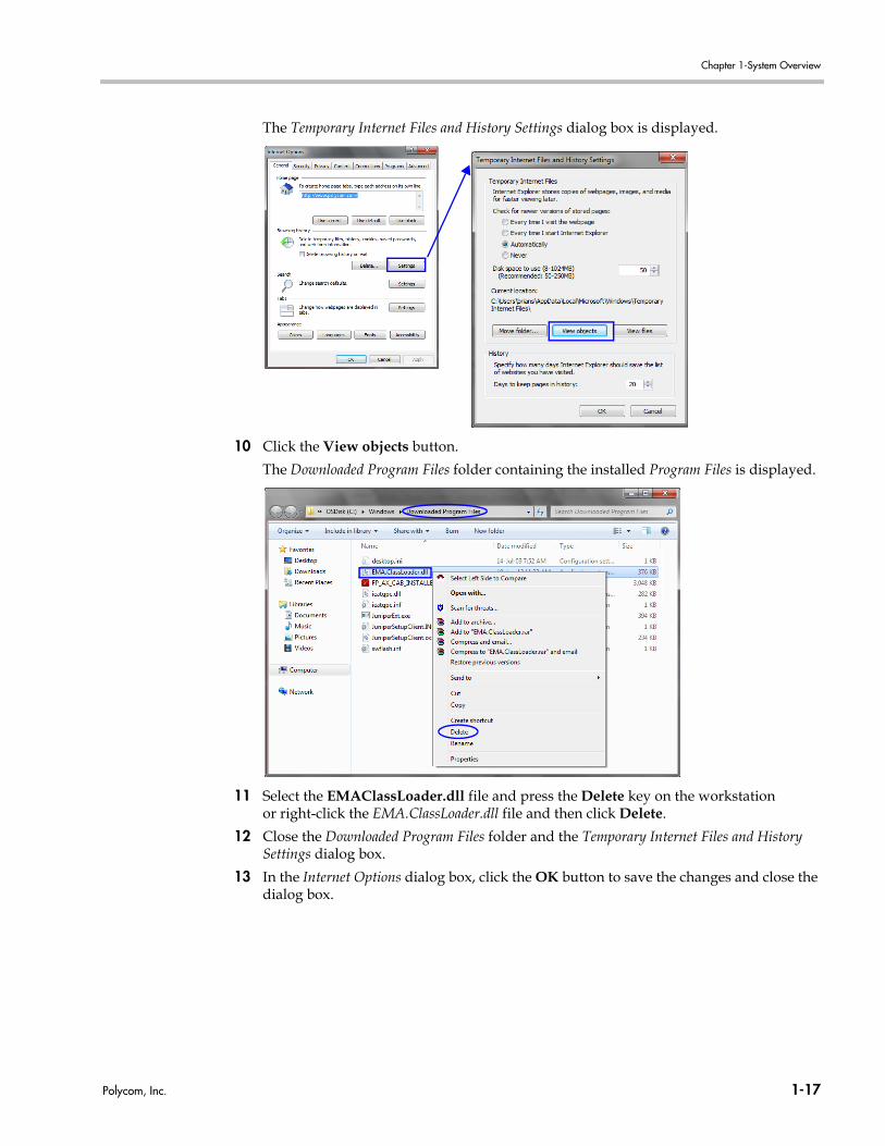
The Temporary Internet Files and History Settings dialog box is displayed.
10 Click the View objects button.
The Downloaded Program Files folder containing the installed Program Files is displayed.
11 Select the EMAClassLoader.dll file and press the Delete key on the workstation or right-click the EMA.ClassLoader.dll file and then click Delete.
12 Close the Downloaded Program Files folder and the Temporary Internet Files and History Settings dialog box.
13 In the Internet Options dialog box, click the OK button to save the changes and close the dialog box.
Polycom, Inc. 1-17

Polycom® RealPresence Collaboration Server (RMX) 1500/2000/4000 Getting Started Guide
1-18 Polycom, Inc.
2
First Time Installation and ConfigurationFirst Time Installation and Configuration of the RealPresence Collaboration Server (RMX) 1500/2000/4000 Virtual Edition consists of the following procedures:1 Preparations:
— Gather Network Equipment and Address Information - get the information needed for integrating the RealPresence Collaboration Server (RMX) 1500/2000/4000 into the local network.
— Unpack the Polycom® RealPresence Collaboration Server (RMX) 1500/2000/4000.— Modify the Management Network parameters on the USB memory stick.
2 Hardware Installation and Setup
— Mount the Collaboration Server in a rack.— Connect the necessary cables.
3 First Entry Power-up and Configuration
— Power up the RealPresence Collaboration Server (RMX) 1500/2000/4000.— Register the RealPresence Collaboration Server (RMX) 1500/2000/4000.— Connect to the RealPresence Collaboration Server (RMX) 1500/2000/4000.— Configure the Default IP Network Service.— Configure the ISDN/PSTN Network Service.
Preparations
Gather Network Equipment and Address Information
IP Services
The IP addresses and network parameters which enable communication between the Polycom® RealPresence Collaboration Server (RMX) 1500/2000/4000, its management application and the conferencing devices are organized in two IP services: • Management Network (Control Unit)• Default IP Service (Conferencing Service which includes the signaling and media)During the First Entry Configuration, the parameters of these two network services are modified to comply with your local network settings.
HardwareInstallationand Setup
First EntryPower-up and Configuration
Preparations
Preparations
HardwareInstallation
and Setup
First EntryPower-up and Configuration
Polycom, Inc. 2-1
Polycom® RealPresence Collaboration Server (RMX) 1500/2000/4000 Getting Started Guide
Management Network
The Management Network enables communication between the RealPresence Collaboration Server (RMX) 1500/2000/4000 and the Collaboration Server Web Client and is used to manage the MCU.The Collaboration Server is shipped with default IP addresses as listed in Table 2-1.
Management Network DefinitionThe configuration of the Management Network can be done by two methods: • USB Memory Stick (recommended method) – The system is shipped with a USB
Memory Stick containing the default IP addresses for the Control Unit and the shelf management.These IP addresses are first modified in the administrator’s PC and then uploaded to the RealPresence Collaboration Server (RMX) 1500/2000/4000.
• Direct connection – Creating a private network between the RealPresence Collaboration Server (RMX) 1500/2000/4000 and the computer and modifying the management network parameters using Fast Configuration Wizard in the Collaboration Server Web Client.For more information, see the RealPresence Collaboration Server (RMX) 1500/2000/4000 Administrator’s Guide, "Configuring Direct Connections to the Collaboration Server” on page F-1.
DHCP is not supported in the Management Network.
Default IP Service (Conferencing Service)
The Default IP Service (Conferencing Service) is used to configure and manage communications between the RealPresence Collaboration Server (RMX) 1500/2000/4000 and conferencing devices.
IP Network Services Required Information
When installing the RealPresence Collaboration Server (RMX) 1500/2000/4000, these default IP addresses must be modified to your local network settings. Therefore it is important that before powering up the RealPresence Collaboration Server (RMX) 1500/2000/4000 for the first time, that you obtain the information needed to complete the Local Network Settings section of the table from your network administrator.
For each MCU, an IP address must be allocated in the local network for the:• Control Unit• Signaling Host• Shelf Management (optional for RealPresence Collaboration Server (RMX) 1500)An additional IP address is also required for any type of MPM card installed in the Collaboration Server. Examples:• RealPresence Collaboration Server (RMX) 1500 - the network administrator should
allocate:
Conferencing (Media and signaling) and Management networks can be logically separated on the Collaboration Server to provide enhanced security. Up to threetwo eightmedia and signaling networks can be defined. For more information see “Multiple Networks” in the RealPresence Collaboration Server (RMX) 1500/2000/4000 Administrator’s Guide.
2-2 Polycom, Inc.
Chapter 2-First Time Installation and Configuration
— Three IP addresses in the local network for an Collaboration Server. — Four IP addresses in the local network for an Collaboration Server, if a separate
Shelf Management IP Address is required.• RealPresence Collaboration Server (RMX) 2000 - the network administrator should
allocate: Collaboration Server— four IP addresses in the local network for an Collaboration Server with one MPM+/
MPMx card. — five IP addresses for an Collaboration Server with two MPM+/MPMx cards.
• RealPresence Collaboration Server (RMX) 4000 - the network administrator should allocate: — four IP addresses in the local network for an Collaboration Server with one MPM+/
MPMx card.— up to seven IP addresses for an Collaboration Server with up to four MPM+/MPMx
cards.
From Version 8.0, MPM+ media cards are not supported.
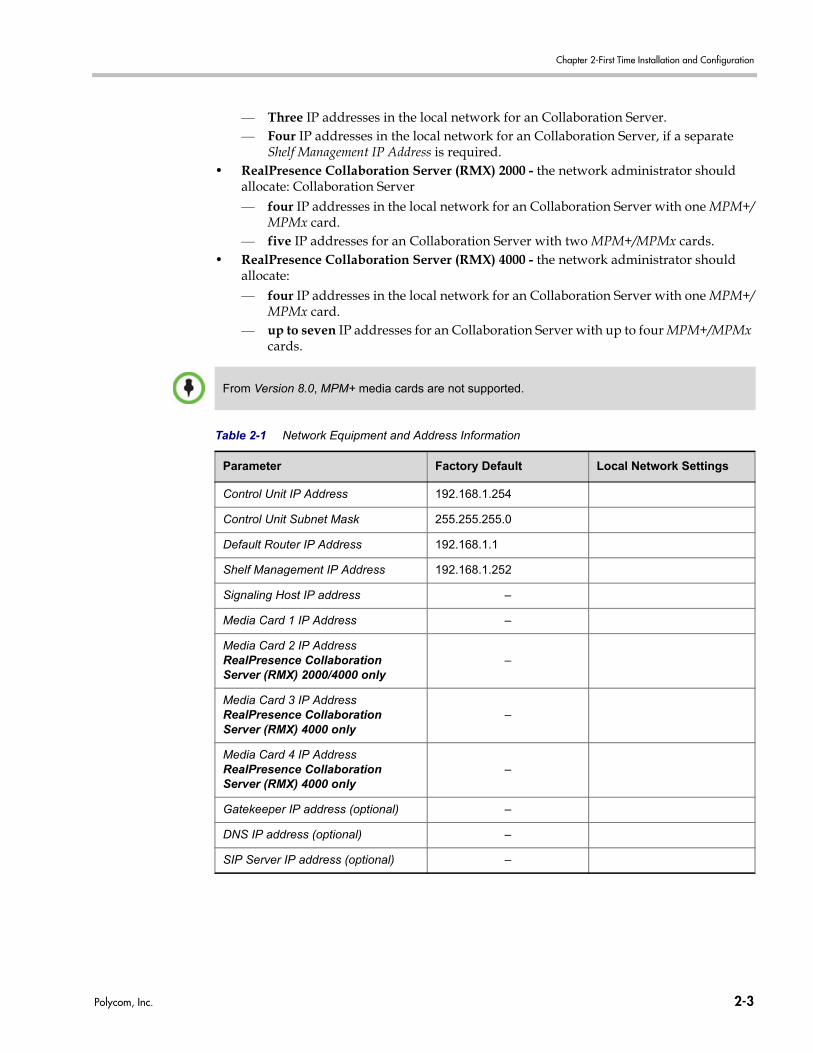
Table 2-1 Network Equipment and Address Information
Parameter Factory Default Local Network Settings
Control Unit IP Address 192.168.1.254
Control Unit Subnet Mask 255.255.255.0
Default Router IP Address 192.168.1.1
Shelf Management IP Address 192.168.1.252
Signaling Host IP address –
Media Card 1 IP Address –
Media Card 2 IP AddressRealPresence Collaboration Server (RMX) 2000/4000 only
–
Media Card 3 IP AddressRealPresence Collaboration Server (RMX) 4000 only
–
Media Card 4 IP AddressRealPresence Collaboration Server (RMX) 4000 only
–
Gatekeeper IP address (optional) –
DNS IP address (optional) –
SIP Server IP address (optional) –
Polycom, Inc. 2-3
Polycom® RealPresence Collaboration Server (RMX) 1500/2000/4000 Getting Started Guide
ISDN/PSTN Services
The ISDN/PSTN Network Service is used to define the properties of the ISDN/PSTN switch and the ISDN lines running from the ISDN/PSTN switch to the ISDN card installed in the Collaboration Server.Before configuring the ISDN/PSTN Network Service, obtain the following information from your ISDN/PSTN Service Provider:• Switch Type• Line Coding and Framing• Numbering Plan• Numbering Type• Dial-in number range
Unpacking the RealPresence Collaboration Server (RMX)
Unpacking the RealPresence Collaboration Server (RMX) 1500
To unpack and lift the RealPresence Collaboration Server (RMX) 1500:1 When you receive the RealPresence Collaboration Server (RMX) 1500 packing case,
inspect the equipment for damage and verify that the components match the packing slip.
2 Open the top cover of the packing case.
Boxes are placed on the top Stratocell® and contain the following:— Installation Accessories. This kit contains the power cables, 3 ethernet cables, USB
key and documentation.— Rack Installation Accessories. This kit contains the accessories for the 19” rack. For
more details, see "Telescopic Rail Runners Accessory Kit” on page 2-7.— Optional - ISDN Package. Contains the ISDN card and ISDN Software License for
ISDN/PSTN.
Make sure that boxes contain all the required parts.
Unpacking the RealPresence Collaboration Server (RMX) 2000
To unpack and lift the RealPresence Collaboration Server (RMX) 2000:1 When you receive the RealPresence Collaboration Server (RMX) 2000 packing case,
inspect the equipment for damage and verify that the components match the packing slip.
2 Open the top cover of the packing case.
Boxes are placed on the top Stratocell® and contain the following:— Installation Accessories. This kit contains the power cables, 1 ethernet cable, USB key
and documentation.
If the Collaboration Server is connected to the public ISDN Network, an external CSU or similar equipment is needed.
Write down the Collaboration Server’s serial number that is on a sticker on the back of the unit. It will be needed for product registration later in the process.
2-4 Polycom, Inc.
Chapter 2-First Time Installation and Configuration
— Rack Installation Accessories. This kit contains the accessories for the 19” rack. For more details, see "Telescopic Rail Runners Accessory Kit” on page 2-7.
— Optional - ISDN Package. Contains the ISDN card and ISDN Software License for ISDN/PSTN.
Make sure that boxes contain all the required parts.
Unpacking the RealPresence Collaboration Server (RMX) 4000
To unpack and lift the RealPresence Collaboration Server (RMX) 4000:1 When you receive the RealPresence Collaboration Server (RMX) 4000 packing case,
inspect the equipment for damage and verify that the components match the packing slip.
2 The RealPresence Collaboration Server (RMX) 4000 is shipped in a packing case with Stratocell® packaging, and the top cover must be unlocked and lifted.
Boxes are placed on the top Stratocell® and contain the following:— Installation Accessories. This kit contains the power cables, 4 ethernet cables, USB
key and documentation.— Rack Installation Accessories. This kit contains the accessories for the 19” rack. For
more details, see "Telescopic Rail Runners Accessory Kit” on page 2-7.
— Optional - ISDN Package. Contains the ISDN card and ISDN Software License.
Make sure that boxes contain all the required parts.
Write down the Collaboration Server’s serial number that is on a sticker on the back of the unit. It will be needed for product registration later in the process.
Write down the Collaboration Server’s serial number that is on a sticker on the back of the unit. It will be needed for product registration later in the process.
Polycom, Inc. 2-5
Polycom® RealPresence Collaboration Server (RMX) 1500/2000/4000 Getting Started Guide
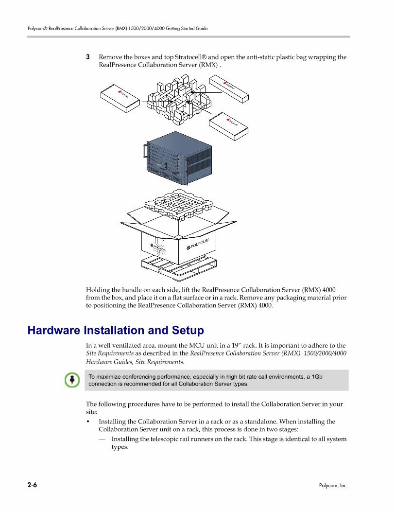
3 Remove the boxes and top Stratocell® and open the anti-static plastic bag wrapping the RealPresence Collaboration Server (RMX) .
Holding the handle on each side, lift the RealPresence Collaboration Server (RMX) 4000 from the box, and place it on a flat surface or in a rack. Remove any packaging material prior to positioning the RealPresence Collaboration Server (RMX) 4000.
Hardware Installation and SetupIn a well ventilated area, mount the MCU unit in a 19” rack. It is important to adhere to the Site Requirements as described in the RealPresence Collaboration Server (RMX) 1500/2000/4000 Hardware Guides, Site Requirements.
The following procedures have to be performed to install the Collaboration Server in your site:• Installing the Collaboration Server in a rack or as a standalone. When installing the
Collaboration Server unit on a rack, this process is done in two stages:— Installing the telescopic rail runners on the rack. This stage is identical to all system
types.
To maximize conferencing performance, especially in high bit rate call environments, a 1Gb connection is recommended for all Collaboration Server types.
2-6 Polycom, Inc.
Chapter 2-First Time Installation and Configuration
— Mounting the Collaboration Server on the rack using the previously installed rail runners
• Connecting the Collaboration Server to the power source• Connecting the network (LAN and ISDN) cables to the Collaboration Server.
Installing the Telescopic Rail Runners on the Rack
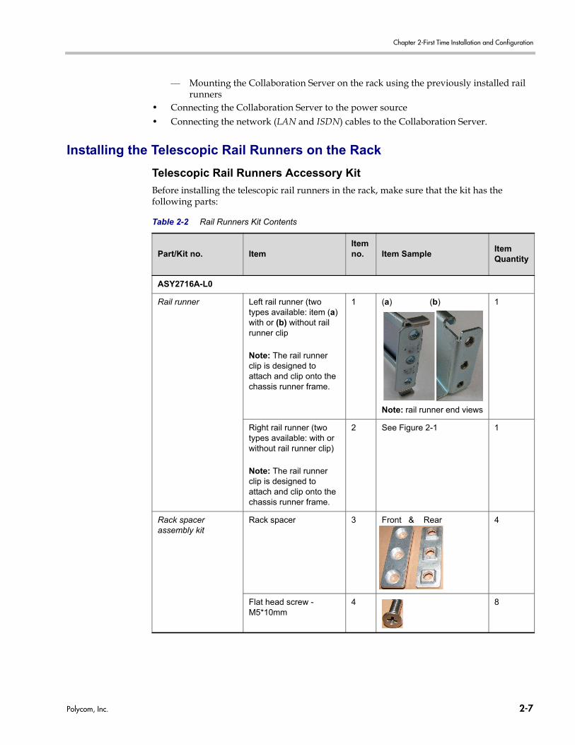
Telescopic Rail Runners Accessory Kit
Before installing the telescopic rail runners in the rack, make sure that the kit has the following parts:
Table 2-2 Rail Runners Kit Contents
Part/Kit no. ItemItem no. Item Sample
Item Quantity
ASY2716A-L0
Rail runner Left rail runner (two types available: item (a) with or (b) without rail runner clip
Note: The rail runner clip is designed to attach and clip onto the chassis runner frame.
1 (a) (b)
Note: rail runner end views
1
Right rail runner (two types available: with or without rail runner clip)
Note: The rail runner clip is designed to attach and clip onto the chassis runner frame.
2 See Figure 2-1 1
Rack spacer assembly kit
Rack spacer 3 Front & Rear 4
Flat head screw - M5*10mm
4 8
Polycom, Inc. 2-7
Polycom® RealPresence Collaboration Server (RMX) 1500/2000/4000 Getting Started Guide
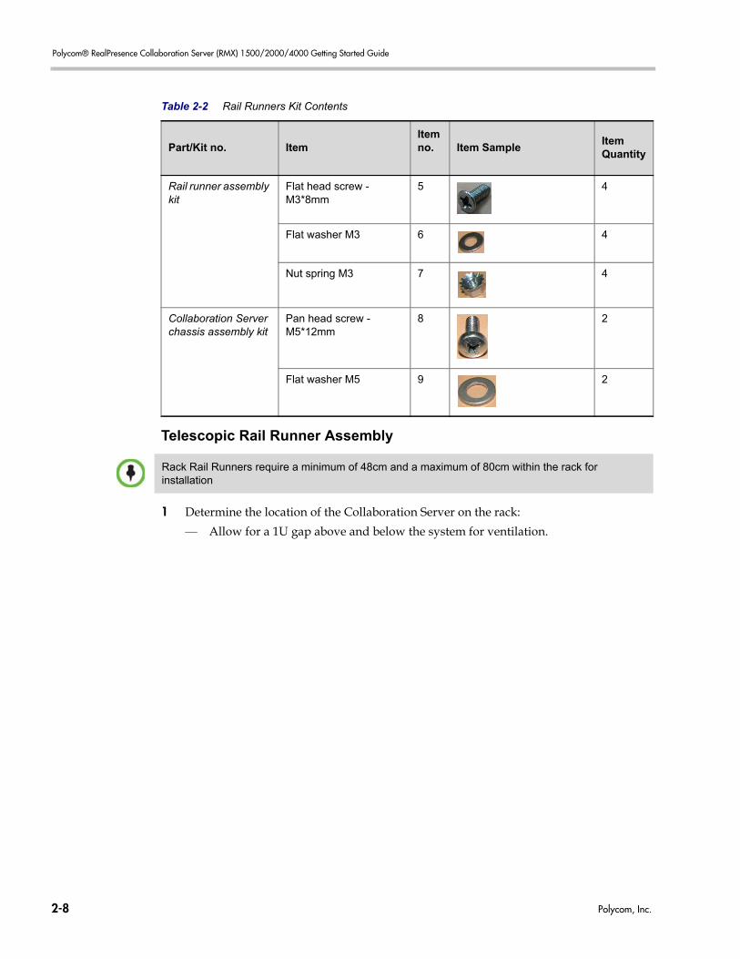
Telescopic Rail Runner Assembly
1 Determine the location of the Collaboration Server on the rack:
— Allow for a 1U gap above and below the system for ventilation.
Rail runner assembly kit
Flat head screw - M3*8mm
5 4
Flat washer M3 6 4
Nut spring M3 7 4
Collaboration Server chassis assembly kit
Pan head screw - M5*12mm
8 2
Flat washer M5 9 2
Table 2-2 Rail Runners Kit Contents
Part/Kit no. ItemItem no. Item Sample
Item Quantity
Rack Rail Runners require a minimum of 48cm and a maximum of 80cm within the rack for installation
2-8 Polycom, Inc.
Chapter 2-First Time Installation and Configuration
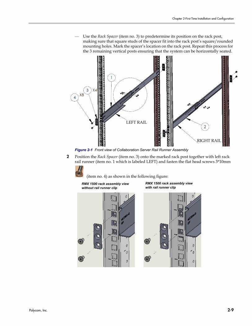
— Use the Rack Spacer (item no. 3) to predetermine its position on the rack post, making sure that square studs of the spacer fit into the rack post’s square/rounded mounting holes. Mark the spacer’s location on the rack post. Repeat this process for the 3 remaining vertical posts ensuring that the system can be horizontally seated.
Figure 2-1 Front view of Collaboration Server Rail Runner Assembly
2 Position the Rack Spacer (item no. 3) onto the marked rack post together with left rack rail runner (item no. 1 which is labeled LEFT) and fasten the flat head screws 3*10mm
(item no. 4) as shown in the following figure:
LEFT RAIL
RIGHT RAIL
RMX 1500 rack assembly view without rail runner clip
RMX 1500 rack assembly view with rail runner clip
Polycom, Inc. 2-9
Polycom® RealPresence Collaboration Server (RMX) 1500/2000/4000 Getting Started Guide
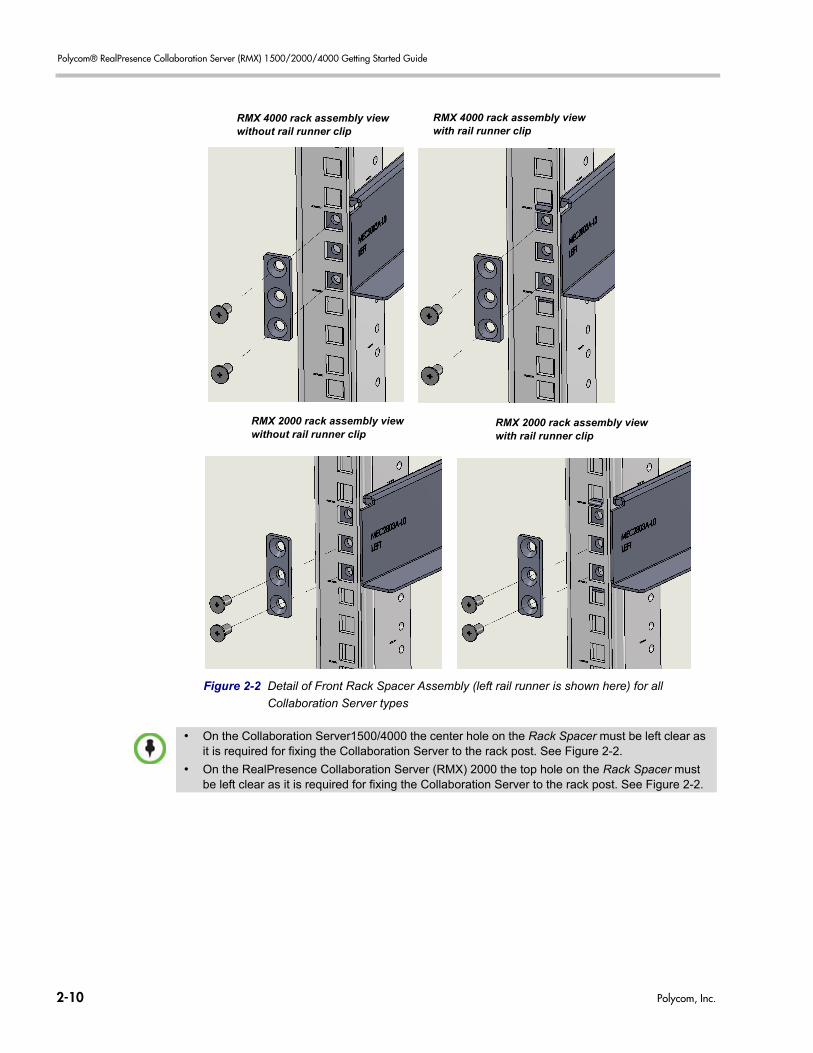
Figure 2-2 Detail of Front Rack Spacer Assembly (left rail runner is shown here) for all
Collaboration Server types
RMX 4000 rack assembly view without rail runner clip
RMX 4000 rack assembly view with rail runner clip
RMX 2000 rack assembly view without rail runner clip
RMX 2000 rack assembly view with rail runner clip
• On the Collaboration Server1500/4000 the center hole on the Rack Spacer must be left clear as it is required for fixing the Collaboration Server to the rack post. See Figure 2-2.
• On the RealPresence Collaboration Server (RMX) 2000 the top hole on the Rack Spacer must be left clear as it is required for fixing the Collaboration Server to the rack post. See Figure 2-2.
2-10 Polycom, Inc.
Chapter 2-First Time Installation and Configuration
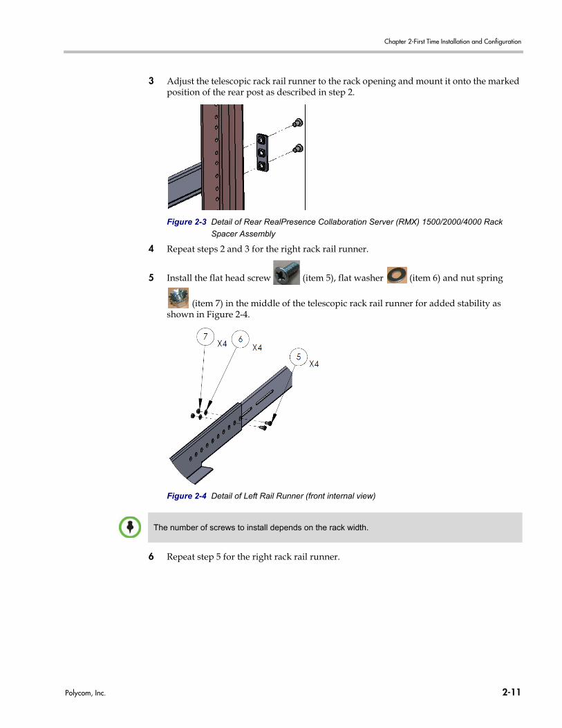
3 Adjust the telescopic rack rail runner to the rack opening and mount it onto the marked position of the rear post as described in step 2.
Figure 2-3 Detail of Rear RealPresence Collaboration Server (RMX) 1500/2000/4000 Rack
Spacer Assembly
4 Repeat steps 2 and 3 for the right rack rail runner.
5 Install the flat head screw (item 5), flat washer (item 6) and nut spring
(item 7) in the middle of the telescopic rack rail runner for added stability as shown in Figure 2-4.
Figure 2-4 Detail of Left Rail Runner (front internal view)
6 Repeat step 5 for the right rack rail runner.
The number of screws to install depends on the rack width.
Polycom, Inc. 2-11
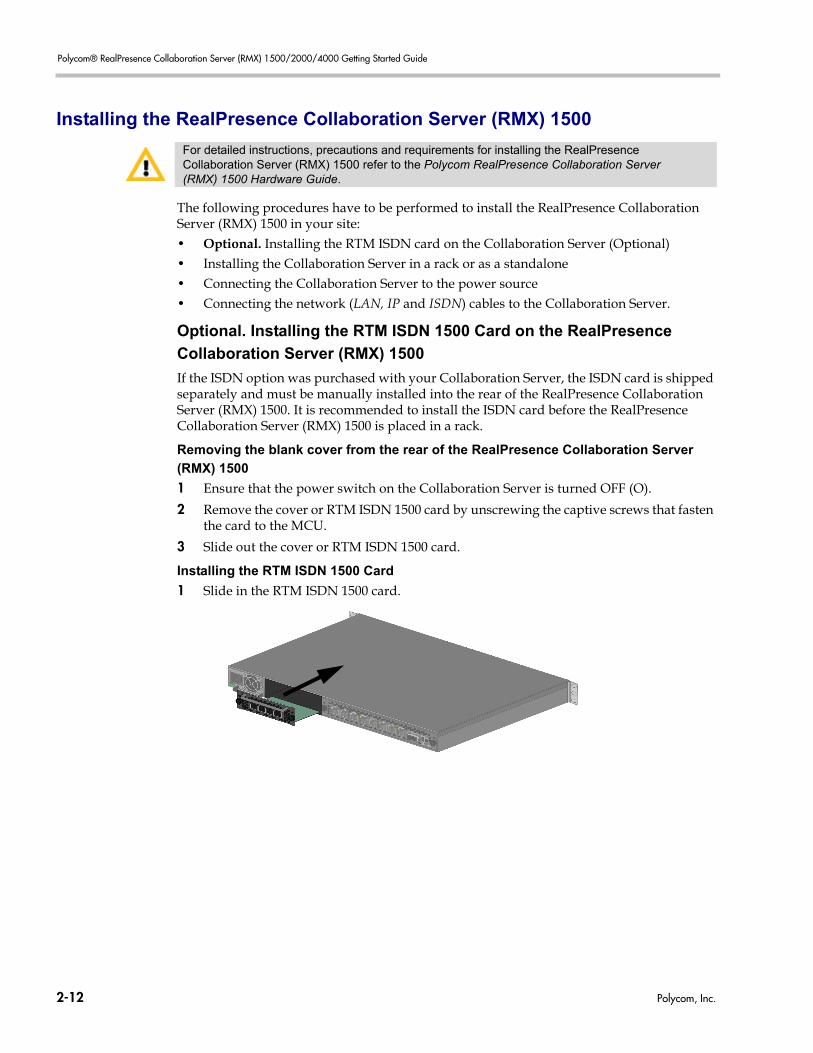
Polycom® RealPresence Collaboration Server (RMX) 1500/2000/4000 Getting Started Guide
Installing the RealPresence Collaboration Server (RMX) 1500
The following procedures have to be performed to install the RealPresence Collaboration Server (RMX) 1500 in your site:• Optional. Installing the RTM ISDN card on the Collaboration Server (Optional)• Installing the Collaboration Server in a rack or as a standalone• Connecting the Collaboration Server to the power source• Connecting the network (LAN, IP and ISDN) cables to the Collaboration Server.
Optional. Installing the RTM ISDN 1500 Card on the RealPresence
Collaboration Server (RMX) 1500
If the ISDN option was purchased with your Collaboration Server, the ISDN card is shipped separately and must be manually installed into the rear of the RealPresence Collaboration Server (RMX) 1500. It is recommended to install the ISDN card before the RealPresence Collaboration Server (RMX) 1500 is placed in a rack.
Removing the blank cover from the rear of the RealPresence Collaboration Server
(RMX) 1500
1 Ensure that the power switch on the Collaboration Server is turned OFF (O).
2 Remove the cover or RTM ISDN 1500 card by unscrewing the captive screws that fasten the card to the MCU.
3 Slide out the cover or RTM ISDN 1500 card.
Installing the RTM ISDN 1500 Card
1 Slide in the RTM ISDN 1500 card.
For detailed instructions, precautions and requirements for installing the RealPresence Collaboration Server (RMX) 1500 refer to the Polycom RealPresence Collaboration Server (RMX) 1500 Hardware Guide.
2-12 Polycom, Inc.
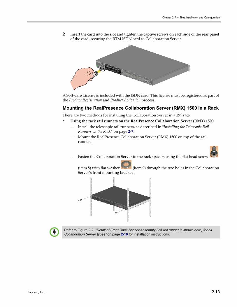
Chapter 2-First Time Installation and Configuration
2 Insert the card into the slot and tighten the captive screws on each side of the rear panel of the card, securing the RTM ISDN card to Collaboration Server.
A Software License is included with the ISDN card. This license must be registered as part of the Product Registration and Product Activation process.
Mounting the RealPresence Collaboration Server (RMX) 1500 in a Rack
There are two methods for installing the Collaboration Server in a 19” rack:• Using the rack rail runners on the RealPresence Collaboration Server (RMX) 1500
— Install the telescopic rail runners, as described in "Installing the Telescopic Rail Runners on the Rack” on page 2-7.
— Mount the RealPresence Collaboration Server (RMX) 1500 on top of the rail runners.
— Fasten the Collaboration Server to the rack spacers using the flat head screw
(item 8) with flat washer (item 9) through the two holes in the Collaboration Server’s front mounting brackets.
Refer to Figure 2-2, "Detail of Front Rack Spacer Assembly (left rail runner is shown here) for all Collaboration Server types” on page 2-10 for installation instructions.
Polycom, Inc. 2-13
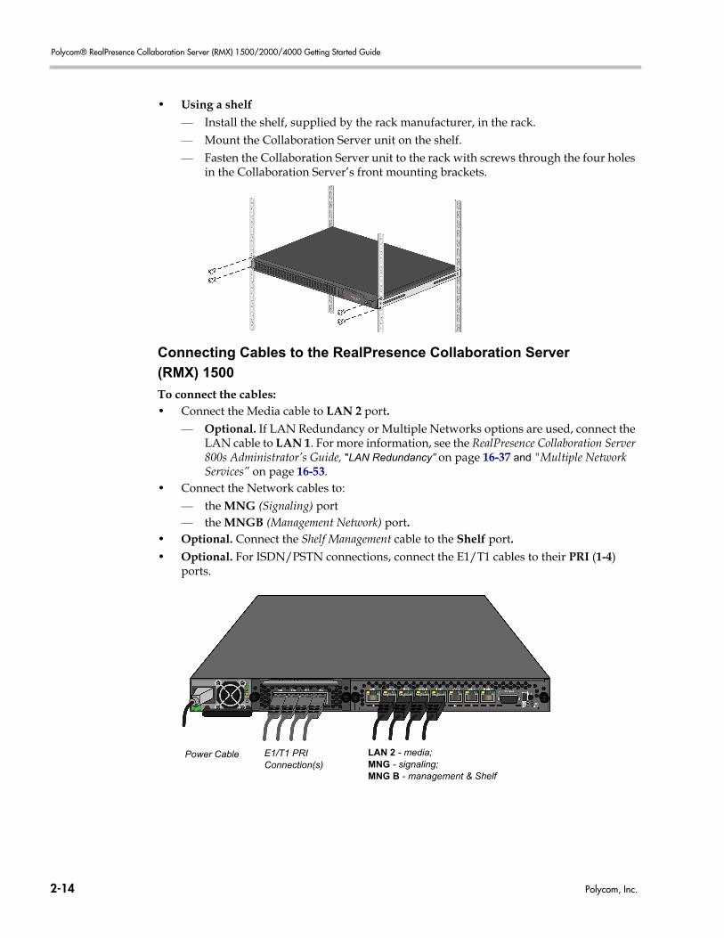
Polycom® RealPresence Collaboration Server (RMX) 1500/2000/4000 Getting Started Guide
• Using a shelf— Install the shelf, supplied by the rack manufacturer, in the rack.— Mount the Collaboration Server unit on the shelf. — Fasten the Collaboration Server unit to the rack with screws through the four holes
in the Collaboration Server’s front mounting brackets.
Connecting Cables to the RealPresence Collaboration Server
(RMX) 1500
To connect the cables:• Connect the Media cable to LAN 2 port.
— Optional. If LAN Redundancy or Multiple Networks options are used, connect the LAN cable to LAN 1. For more information, see the RealPresence Collaboration Server 800s Administrator’s Guide, "LAN Redundancy” on page 16-37 and "Multiple Network Services” on page 16-53.
• Connect the Network cables to: — the MNG (Signaling) port — the MNGB (Management Network) port.
• Optional. Connect the Shelf Management cable to the Shelf port.• Optional. For ISDN/PSTN connections, connect the E1/T1 cables to their PRI (1-4)
ports.
E1/T1 PRI Connection(s)
Power Cable LAN 2 - media; MNG - signaling; MNG B - management & Shelf
2-14 Polycom, Inc.
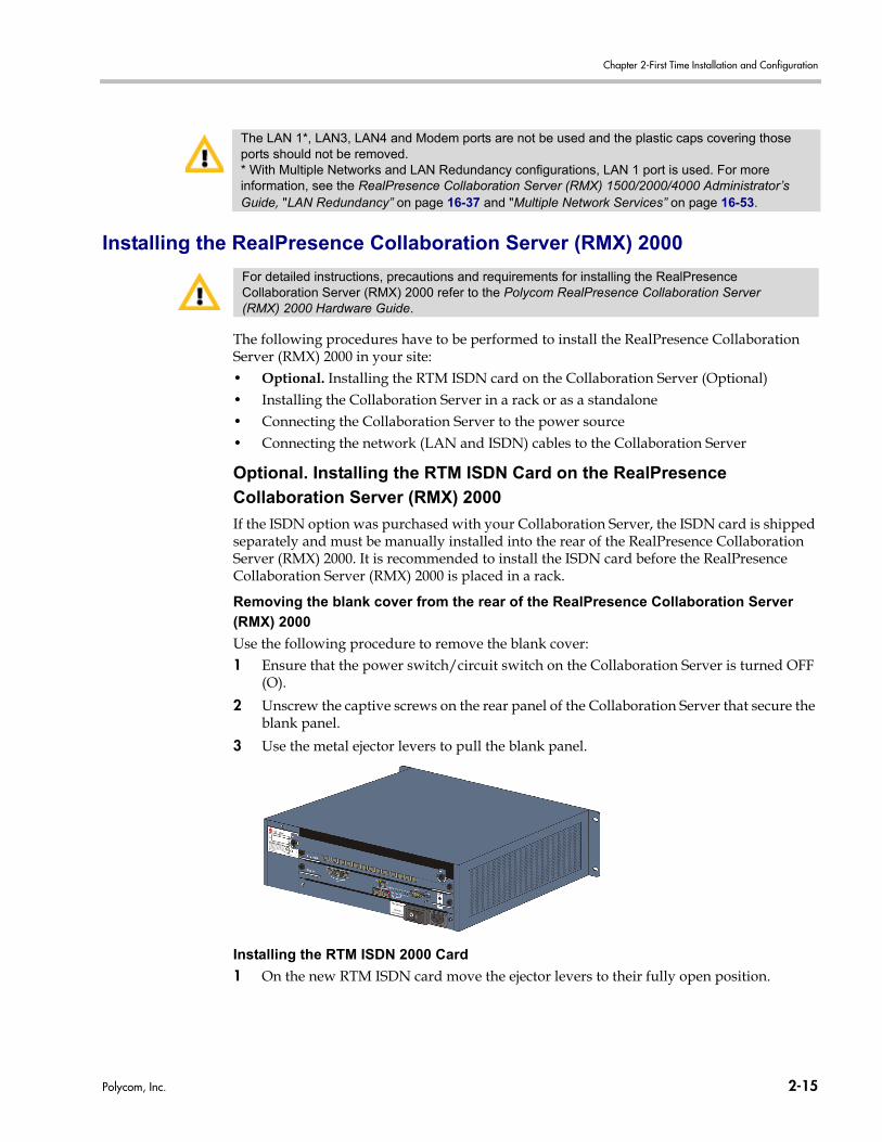
Chapter 2-First Time Installation and Configuration
Installing the RealPresence Collaboration Server (RMX) 2000
The following procedures have to be performed to install the RealPresence Collaboration Server (RMX) 2000 in your site:• Optional. Installing the RTM ISDN card on the Collaboration Server (Optional)• Installing the Collaboration Server in a rack or as a standalone• Connecting the Collaboration Server to the power source• Connecting the network (LAN and ISDN) cables to the Collaboration Server
Optional. Installing the RTM ISDN Card on the RealPresence
Collaboration Server (RMX) 2000
If the ISDN option was purchased with your Collaboration Server, the ISDN card is shipped separately and must be manually installed into the rear of the RealPresence Collaboration Server (RMX) 2000. It is recommended to install the ISDN card before the RealPresence Collaboration Server (RMX) 2000 is placed in a rack.
Removing the blank cover from the rear of the RealPresence Collaboration Server
(RMX) 2000
Use the following procedure to remove the blank cover:1 Ensure that the power switch/circuit switch on the Collaboration Server is turned OFF
(O).
2 Unscrew the captive screws on the rear panel of the Collaboration Server that secure the blank panel.
3 Use the metal ejector levers to pull the blank panel.
Installing the RTM ISDN 2000 Card
1 On the new RTM ISDN card move the ejector levers to their fully open position.
The LAN 1*, LAN3, LAN4 and Modem ports are not be used and the plastic caps covering those ports should not be removed.* With Multiple Networks and LAN Redundancy configurations, LAN 1 port is used. For more information, see the RealPresence Collaboration Server (RMX) 1500/2000/4000 Administrator’s Guide, "LAN Redundancy” on page 16-37 and "Multiple Network Services” on page 16-53.
For detailed instructions, precautions and requirements for installing the RealPresence Collaboration Server (RMX) 2000 refer to the Polycom RealPresence Collaboration Server (RMX) 2000 Hardware Guide.
Polycom, Inc. 2-15
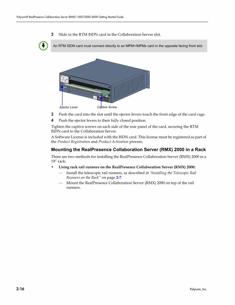
Polycom® RealPresence Collaboration Server (RMX) 1500/2000/4000 Getting Started Guide
2 Slide in the RTM ISDN card in the Collaboration Server slot.
3 Push the card into the slot until the ejector levers touch the front edge of the card cage.
4 Push the ejector levers to their fully closed position.
Tighten the captive screws on each side of the rear panel of the card, securing the RTM ISDN card to the Collaboration Server.A Software License is included with the ISDN card. This license must be registered as part of the Product Registration and Product Activation process.
Mounting the RealPresence Collaboration Server (RMX) 2000 in a Rack
There are two methods for installing the RealPresence Collaboration Server (RMX) 2000 in a 19” rack:• Using rack rail runners on the RealPresence Collaboration Server (RMX) 2000:
— Install the telescopic rail runners, as described in "Installing the Telescopic Rail Runners on the Rack” on page 2-7.
— Mount the RealPresence Collaboration Server (RMX) 2000 on top of the rail runners.
An RTM ISDN card must connect directly to an MPM+/MPMx card in the opposite facing front slot.
Ejector Lever Captive Screw
2-16 Polycom, Inc.
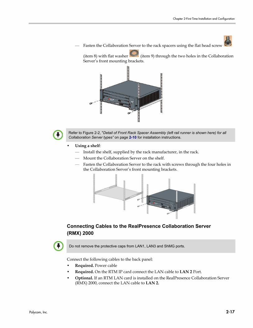
Chapter 2-First Time Installation and Configuration
— Fasten the Collaboration Server to the rack spacers using the flat head screw
(item 8) with flat washer (item 9) through the two holes in the Collaboration Server’s front mounting brackets.
• Using a shelf:— Install the shelf, supplied by the rack manufacturer, in the rack.— Mount the Collaboration Server on the shelf. — Fasten the Collaboration Server to the rack with screws through the four holes in
the Collaboration Server’s front mounting brackets.
Connecting Cables to the RealPresence Collaboration Server
(RMX) 2000
Connect the following cables to the back panel:• Required. Power cable• Required. On the RTM IP card connect the LAN cable to LAN 2 Port.
• Optional. If an RTM LAN card is installed on the RealPresence Collaboration Server (RMX) 2000, connect the LAN cable to LAN 2.
Refer to Figure 2-2, "Detail of Front Rack Spacer Assembly (left rail runner is shown here) for all Collaboration Server types” on page 2-10 for installation instructions.
Do not remove the protective caps from LAN1, LAN3 and ShMG ports.
Polycom, Inc. 2-17
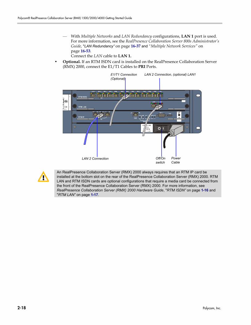
Polycom® RealPresence Collaboration Server (RMX) 1500/2000/4000 Getting Started Guide
— With Multiple Networks and LAN Redundancy configurations, LAN 1 port is used. For more information, see the RealPresence Collaboration Server 800s Administrator’s Guide, "LAN Redundancy” on page 16-37 and "Multiple Network Services” on page 16-53.Connect the LAN cable to LAN 1.
• Optional. If an RTM ISDN card is installed on the RealPresence Collaboration Server (RMX) 2000, connect the E1/T1 Cables to PRI Ports.
LAN 2 Connection Power Cable
Off/On switch
E1/T1 Connection (Optional)
LAN 2 Connection, (optional) LAN1
An RealPresence Collaboration Server (RMX) 2000 always requires that an RTM IP card be installed at the bottom slot on the rear of the RealPresence Collaboration Server (RMX) 2000. RTM LAN and RTM ISDN cards are optional configurations that require a media card be connected from the front of the RealPresence Collaboration Server (RMX) 2000. For more information, see RealPresence Collaboration Server (RMX) 2000 Hardware Guide, "RTM ISDN” on page 1-16 and "RTM LAN” on page 1-17.
2-18 Polycom, Inc.
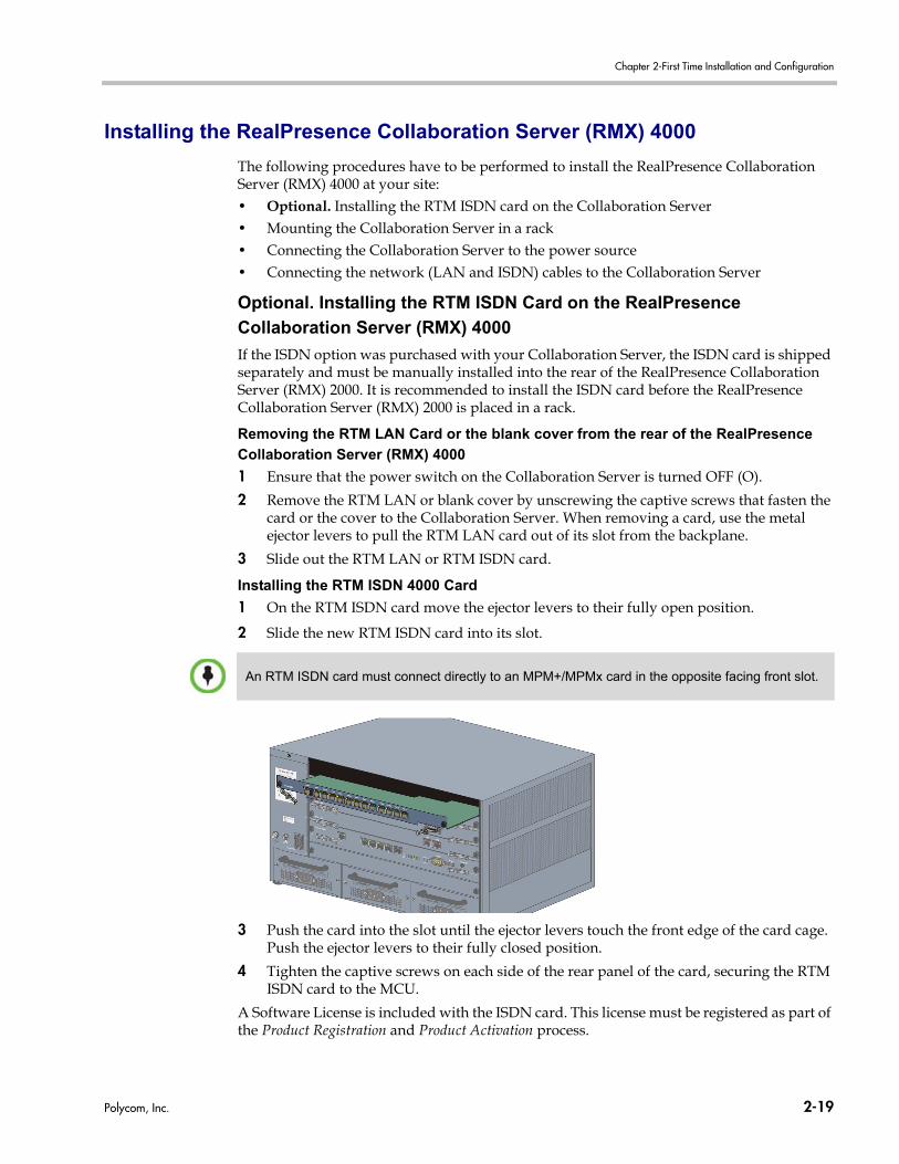
Chapter 2-First Time Installation and Configuration
Installing the RealPresence Collaboration Server (RMX) 4000
The following procedures have to be performed to install the RealPresence Collaboration Server (RMX) 4000 at your site:• Optional. Installing the RTM ISDN card on the Collaboration Server• Mounting the Collaboration Server in a rack• Connecting the Collaboration Server to the power source• Connecting the network (LAN and ISDN) cables to the Collaboration Server
Optional. Installing the RTM ISDN Card on the RealPresence
Collaboration Server (RMX) 4000
If the ISDN option was purchased with your Collaboration Server, the ISDN card is shipped separately and must be manually installed into the rear of the RealPresence Collaboration Server (RMX) 2000. It is recommended to install the ISDN card before the RealPresence Collaboration Server (RMX) 2000 is placed in a rack.
Removing the RTM LAN Card or the blank cover from the rear of the RealPresence
Collaboration Server (RMX) 4000
1 Ensure that the power switch on the Collaboration Server is turned OFF (O).
2 Remove the RTM LAN or blank cover by unscrewing the captive screws that fasten the card or the cover to the Collaboration Server. When removing a card, use the metal ejector levers to pull the RTM LAN card out of its slot from the backplane.
3 Slide out the RTM LAN or RTM ISDN card.
Installing the RTM ISDN 4000 Card
1 On the RTM ISDN card move the ejector levers to their fully open position.
2 Slide the new RTM ISDN card into its slot.
3 Push the card into the slot until the ejector levers touch the front edge of the card cage. Push the ejector levers to their fully closed position.
4 Tighten the captive screws on each side of the rear panel of the card, securing the RTM ISDN card to the MCU.
A Software License is included with the ISDN card. This license must be registered as part of the Product Registration and Product Activation process.
An RTM ISDN card must connect directly to an MPM+/MPMx card in the opposite facing front slot.
Polycom, Inc. 2-19
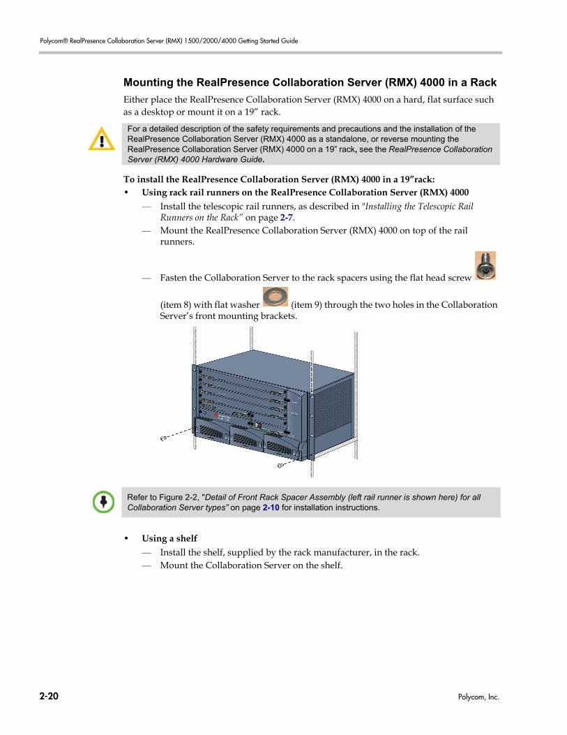
Polycom® RealPresence Collaboration Server (RMX) 1500/2000/4000 Getting Started Guide
Mounting the RealPresence Collaboration Server (RMX) 4000 in a Rack
Either place the RealPresence Collaboration Server (RMX) 4000 on a hard, flat surface such as a desktop or mount it on a 19” rack.
To install the RealPresence Collaboration Server (RMX) 4000 in a 19”rack:• Using rack rail runners on the RealPresence Collaboration Server (RMX) 4000
— Install the telescopic rail runners, as described in "Installing the Telescopic Rail Runners on the Rack” on page 2-7.
— Mount the RealPresence Collaboration Server (RMX) 4000 on top of the rail runners.
— Fasten the Collaboration Server to the rack spacers using the flat head screw
(item 8) with flat washer (item 9) through the two holes in the Collaboration Server’s front mounting brackets.
• Using a shelf — Install the shelf, supplied by the rack manufacturer, in the rack.— Mount the Collaboration Server on the shelf.
For a detailed description of the safety requirements and precautions and the installation of the RealPresence Collaboration Server (RMX) 4000 as a standalone, or reverse mounting the RealPresence Collaboration Server (RMX) 4000 on a 19” rack, see the RealPresence Collaboration Server (RMX) 4000 Hardware Guide.
Refer to Figure 2-2, "Detail of Front Rack Spacer Assembly (left rail runner is shown here) for all Collaboration Server types” on page 2-10 for installation instructions.
2-20 Polycom, Inc.
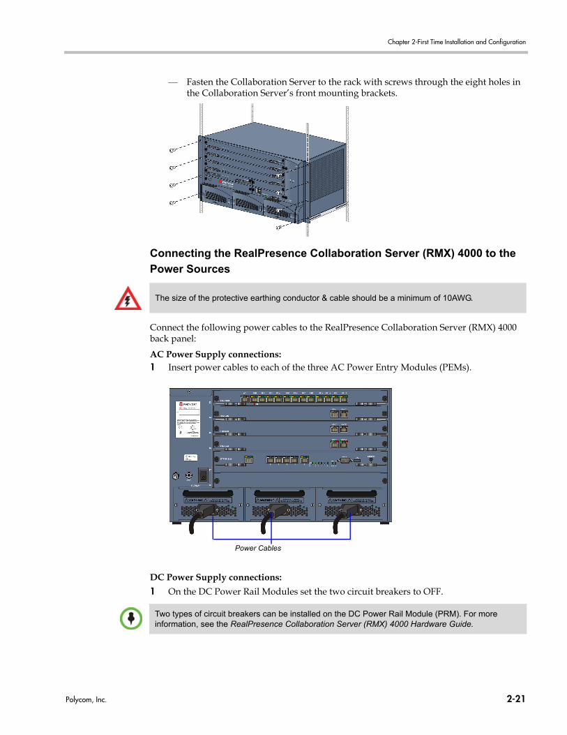
Chapter 2-First Time Installation and Configuration
— Fasten the Collaboration Server to the rack with screws through the eight holes in the Collaboration Server’s front mounting brackets.
Connecting the RealPresence Collaboration Server (RMX) 4000 to the
Power Sources
Connect the following power cables to the RealPresence Collaboration Server (RMX) 4000 back panel:
AC Power Supply connections:1 Insert power cables to each of the three AC Power Entry Modules (PEMs).
DC Power Supply connections:
1 On the DC Power Rail Modules set the two circuit breakers to OFF.
The size of the protective earthing conductor & cable should be a minimum of 10AWG.
Power Cables
Two types of circuit breakers can be installed on the DC Power Rail Module (PRM). For more information, see the RealPresence Collaboration Server (RMX) 4000 Hardware Guide.
Polycom, Inc. 2-21
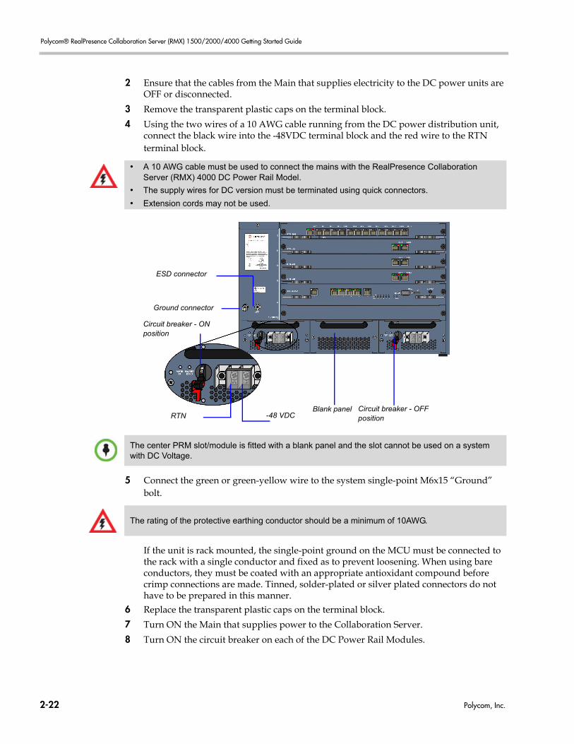
Polycom® RealPresence Collaboration Server (RMX) 1500/2000/4000 Getting Started Guide
2 Ensure that the cables from the Main that supplies electricity to the DC power units are OFF or disconnected.
3 Remove the transparent plastic caps on the terminal block.
4 Using the two wires of a 10 AWG cable running from the DC power distribution unit, connect the black wire into the -48VDC terminal block and the red wire to the RTN terminal block.
5 Connect the green or green-yellow wire to the system single-point M6x15 “Ground” bolt.
If the unit is rack mounted, the single-point ground on the MCU must be connected to the rack with a single conductor and fixed as to prevent loosening. When using bare conductors, they must be coated with an appropriate antioxidant compound before crimp connections are made. Tinned, solder-plated or silver plated connectors do not have to be prepared in this manner.
6 Replace the transparent plastic caps on the terminal block.
7 Turn ON the Main that supplies power to the Collaboration Server.
8 Turn ON the circuit breaker on each of the DC Power Rail Modules.
• A 10 AWG cable must be used to connect the mains with the RealPresence Collaboration Server (RMX) 4000 DC Power Rail Model.
• The supply wires for DC version must be terminated using quick connectors.
• Extension cords may not be used.
ESD connector
Circuit breaker - ONposition
-48 VDCRTN
Ground connector
Blank panel Circuit breaker - OFFposition
The center PRM slot/module is fitted with a blank panel and the slot cannot be used on a system with DC Voltage.
The rating of the protective earthing conductor should be a minimum of 10AWG.
2-22 Polycom, Inc.
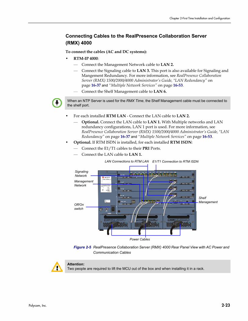
Chapter 2-First Time Installation and Configuration
Connecting Cables to the RealPresence Collaboration Server
(RMX) 4000
To connect the cables (AC and DC systems):
• RTM-IP 4000:— Connect the Management Network cable to LAN 2.— Connect the Signaling cable to LAN 3. This port is also available for Signaling and
Mangement Redundancy. For more information, see RealPresence Collaboration Server (RMX) 1500/2000/4000 Administrator’s Guide, "LAN Redundancy” on page 16-37 and "Multiple Network Services” on page 16-53.
— Connect the Shelf Management cable to LAN 6.
• For each installed RTM LAN - Connect the LAN cable to LAN 2.— Optional. Connect the LAN cable to LAN 1. With Multiple networks and LAN
redundancy configurations, LAN 1 port is used. For more information, see RealPresence Collaboration Server (RMX) 1500/2000/4000 Administrator’s Guide, "LAN Redundancy” on page 16-37 and "Multiple Network Services” on page 16-53.
• Optional. If RTM ISDN is installed, for each installed RTM ISDN:— Connect the E1/T1 cables to their PRI Ports.— Connect the LAN cable to LAN 1.
Figure 2-5 RealPresence Collaboration Server (RMX) 4000 Rear Panel View with AC Power and
Communication Cables
When an NTP Server is used for the RMX Time, the Shelf Management cable must be connected to the shelf port.
LAN Connections to RTM LAN
Power Cables
Off/On switch
E1/T1 Connection to RTM ISDN
Shelf Management
Management Network
Signaling Network
Attention:Two people are required to lift the MCU out of the box and when installing it in a rack.
Polycom, Inc. 2-23
Polycom® RealPresence Collaboration Server (RMX) 1500/2000/4000 Getting Started Guide
When LAN redundancy is enabled, LAN 1 is used for both management, media and signaling network connection.Connect the media and signaling cable to LAN 2 port. By default this port is used for signaling, but when LAN redundancy is enabled, LAN 2 is the backup of LAN 1 port.
Modifying the Factory Default Management Network Settings on the USB Memory Stick
The USB memory stick contains a text file, lan.cfg, which holds the factory default IP address parameters. These parameters must be modified to your local network settings using the LAN Configuration Utility, also available on the USB memory stick.
To modify the USB memory stick settings:1 Take the USB memory stick from the Installation Accessories kit and insert it into the PC
workstation. The Polycom RealPresence Collaboration Server (RMX) Documentation Library & Initial Setup Tools window opens.
In Windows XP: — The Polycom Documentation option is automatically selected. Click OK.In Windows 7: — Select Open Folder to view files using Windows Explorer.
2 Double-click the index.hta file.The Language Menu opens, offering a choice of several languages.
In Windows XP: — The Polycom Documentation option is automatically selected. Click OK.
Write down the serial number of the RP Collaboration Server (RMX), located on a sticker on the back of the unit. It will be needed for product registration later in the process.
2-24 Polycom, Inc.
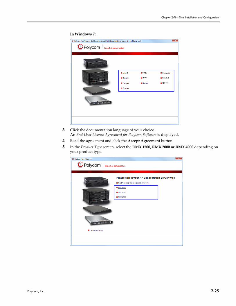
Chapter 2-First Time Installation and Configuration
In Windows 7:
3 Click the documentation language of your choice.An End-User Licence Agreement for Polycom Software is displayed.
4 Read the agreement and click the Accept Agreement button.
5 In the Product Type screen, select the RMX 1500, RMX 2000 or RMX 4000 depending on your product type.
Polycom, Inc. 2-25
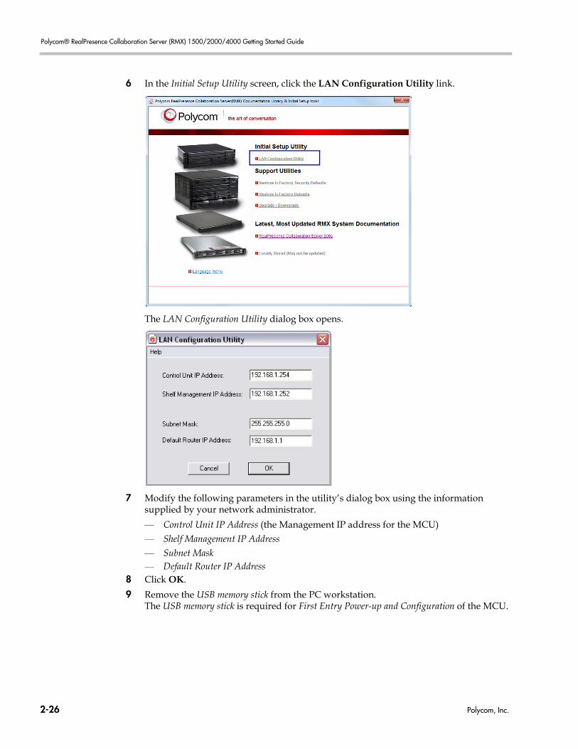
Polycom® RealPresence Collaboration Server (RMX) 1500/2000/4000 Getting Started Guide
6 In the Initial Setup Utility screen, click the LAN Configuration Utility link.
The LAN Configuration Utility dialog box opens.
7 Modify the following parameters in the utility’s dialog box using the information supplied by your network administrator.
— Control Unit IP Address (the Management IP address for the MCU)— Shelf Management IP Address— Subnet Mask— Default Router IP Address
8 Click OK.
9 Remove the USB memory stick from the PC workstation.The USB memory stick is required for First Entry Power-up and Configuration of the MCU.
2-26 Polycom, Inc.
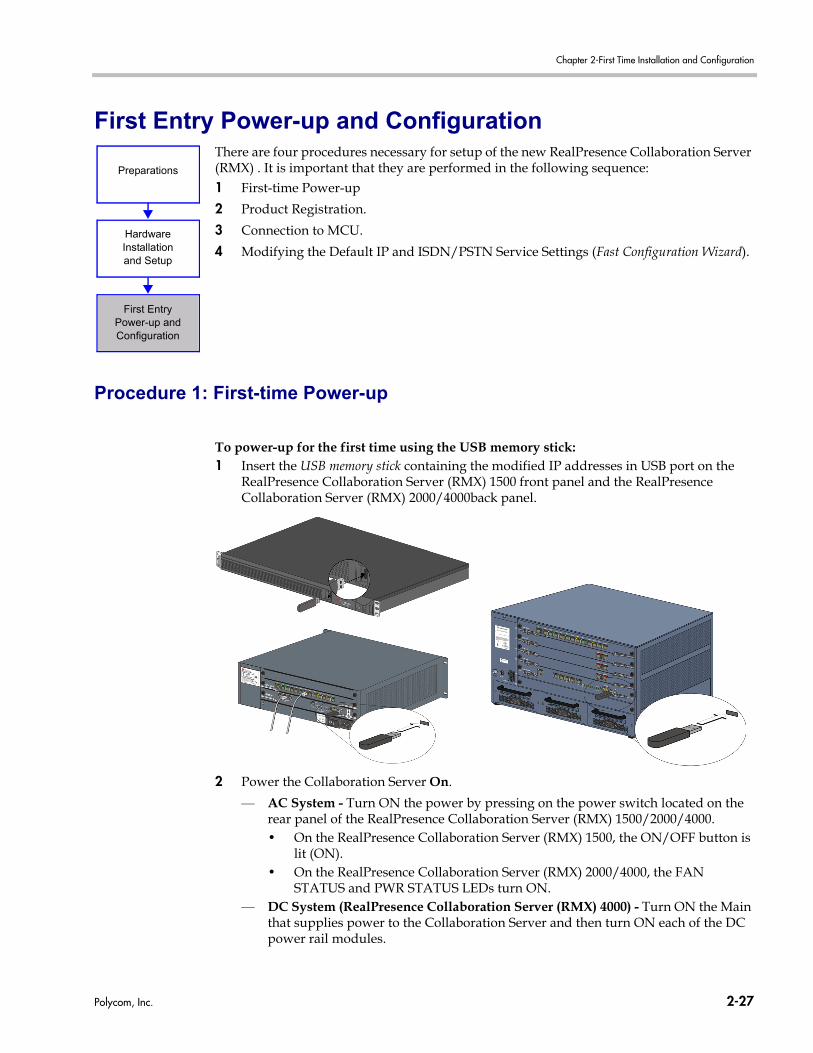
Chapter 2-First Time Installation and Configuration
First Entry Power-up and ConfigurationThere are four procedures necessary for setup of the new RealPresence Collaboration Server (RMX) . It is important that they are performed in the following sequence:1 First-time Power-up
2 Product Registration.
3 Connection to MCU.
4 Modifying the Default IP and ISDN/PSTN Service Settings (Fast Configuration Wizard).
Procedure 1: First-time Power-up
To power-up for the first time using the USB memory stick:1 Insert the USB memory stick containing the modified IP addresses in USB port on the
RealPresence Collaboration Server (RMX) 1500 front panel and the RealPresence Collaboration Server (RMX) 2000/4000back panel.
2 Power the Collaboration Server On.
— AC System - Turn ON the power by pressing on the power switch located on the rear panel of the RealPresence Collaboration Server (RMX) 1500/2000/4000.• On the RealPresence Collaboration Server (RMX) 1500, the ON/OFF button is
lit (ON).• On the RealPresence Collaboration Server (RMX) 2000/4000, the FAN
STATUS and PWR STATUS LEDs turn ON.— DC System (RealPresence Collaboration Server (RMX) 4000) - Turn ON the Main
that supplies power to the Collaboration Server and then turn ON each of the DC power rail modules.
Preparations
HardwareInstallationand Setup
First EntryPower-up and Configuration
Polycom, Inc. 2-27
Polycom® RealPresence Collaboration Server (RMX) 1500/2000/4000 Getting Started Guide
System power-up sequence may take approximately 10 minutes.During this time, the parameters in the lan.cfg file are uploaded from the USB memory stick to the MCU’s memory and applied during the power-up sequence.Wait for the upload process to complete. Initially, all the READY/IN USE/ERROR LEDs on the RealPresence Collaboration Server (RMX) 1500 or ERR/RDY/ACT LEDs on the RealPresence Collaboration Server (RMX) 2000/4000 flicker and flash. Upload is completed when all the LEDs turn off and only the red ERROR/ERR LED (on the CTNL unit of the RealPresence Collaboration Server (RMX) 2000/4000) remains ON. It remains ON until the Default IP Network Service is configured. For more details, see "Fast Configuration Wizard” on page 2-31.Do not remove the USB memory stick from the RealPresence Collaboration Server (RMX) 1500/2000/4000 until the connection with the MCU is established and the Login screen of the Collaboration Server Web Client is displayed. For more details, see "Procedure 3: Connection to MCU” on page 2-29.
Procedure 2: Product Registration
Before the RealPresence Collaboration Server (RMX) 1500/2000/4000 can be used, it is necessary to register the product and the various software licenses and obtain an Activation Key.During first-time power-up, the Product Activation dialog box is displayed in the Collaboration Server Web Client, requesting you to enter an Activation Key.
Obtaining the Activation Key
1 Access the Service & Support page of the Polycom website at: http://support.polycom.com
2 Log in with your Email Address and Password or register as a new user.
3 Select Product Registration.
4 Follow the on-screen instructions for Product Registration and Product Activation. (The MCU’s serial number on the product sticker on the back of the unit.)For more information, refer to the Collaboration Server Software Licence document you received with your shipment.
5 When the Product Activation Key is displayed, write it down or copy it for later pasting into the Activation Key field of the Product Activation dialog box.
From version 8.1 onwards, a license is required for SVC conferencing.
Register all Polycom Software Licences that you have purchased when obtaining the Activation Key. For example, ISDN, Encryption and Multiple Networks each have different Polycom Software Licenses.
2-28 Polycom, Inc.
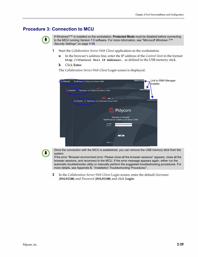
Chapter 2-First Time Installation and Configuration
Procedure 3: Connection to MCU
1 Start the Collaboration Server Web Client application on the workstation.
a In the browser’s address line, enter the IP address of the Control Unit in the format: http://<Control Unit IP Address>, as defined in the USB memory stick.
b Click Enter.
The Collaboration Server Web Client Login screen is displayed.
2 In the Collaboration Server Web Client Login screen, enter the default Username (POLYCOM) and Password (POLYCOM) and click Login.
If Windows7™ is installed on the workstation, Protected Mode must be disabled before connecting to the MCU running Version 7.0 software. For more information, see "Microsoft Windows 7™ Security Settings” on page 1-14.
Link to RMX ManagerInstaller
Once the connection with the MCU is established, you can remove the USB memory stick from the system.If the error “Browser environment error. Please close all the browser sessions” appears, close all the browser sessions, and reconnect to the MCU. If the error message appears again, either run the automatic troubleshooter utility or manually perform the suggested troubleshooting procedures. For more details, see Appendix B, “Installation Troubleshooting Procedures” .
Polycom, Inc. 2-29

Polycom® RealPresence Collaboration Server (RMX) 1500/2000/4000 Getting Started Guide
The Collaboration Server Web Client opens and the Product Activation dialog box appears with the serial number filled in:
3 Select the “I accept the license agreement” check box to enable Online Registration of your product.
4 In the Activation Key field, enter or paste the Product Activation Key obtained earlier.
If you did not register your product earlier in the process and you do not have an Activation Key, click the Polycom Resource Center button to access the Service & Support page of the Polycom Support website.
5 Click OK.A message indicating that the Product Activation Key was loaded successfully appears. If the Product Activation Key fails to load, please contact your vendor.
6 Click OK.
On the MPM+/MPMx card of the RealPresence Collaboration Server (RMX) 2000/4000, initially, the ERR/RDY/ACT LEDs all flicker and flash, until only the RDY LED turns ON on the media card, while the ERR LED on the CTNL unit is still ON.
If the Product Activation dialog box does not appear, go to Setup --> Product Activation to display the dialog box.
2-30 Polycom, Inc.
Chapter 2-First Time Installation and Configuration
As no Default IP Network Service is defined, the system automatically starts the Fast Configuration Wizard.
Procedure 4: Modifying the Default IP Service and ISDN/PSTN Network Service Settings
The Fast Configuration Wizard is automatically started when no Default IP Network Service is defined and it assists you in configuring the Default IP Network Service. This happens during First Time Power-up, before the service has been defined or if the Signaling Service has been deleted, followed by an Collaboration Server restart.The IP Management Service tab in the Fast Configuration Wizard is enabled only if the factory default Management IP addresses were not modified.
Fast Configuration Wizard
1 Enter the required IP information in the dialog box.
On the RealPresence Collaboration Server (RMX) 1500/2000/4000, IPv4 is the default protocol for setting the Network Service in the Fast Configuration Wizard.If IPv6 addressing is required, complete the Fast Configuration Wizard for IPv4 and then:
1 Modify the Management Network to use IPv6 addressing or IPv4 and IPv6 addressing.
2 Restart the Collaboration Server.
3 Modify the properties of the Default IP Network Service, which will now include IPv6 addressing or IPv4 & IPv6 addressing options to configure the Network Service.
For detailed description of the IP Network Services, see the RealPresence Collaboration Server (RMX) 1500/2000/4000 Administrator’s Guide, "Network Services” on page 16-1.
Polycom, Inc. 2-31
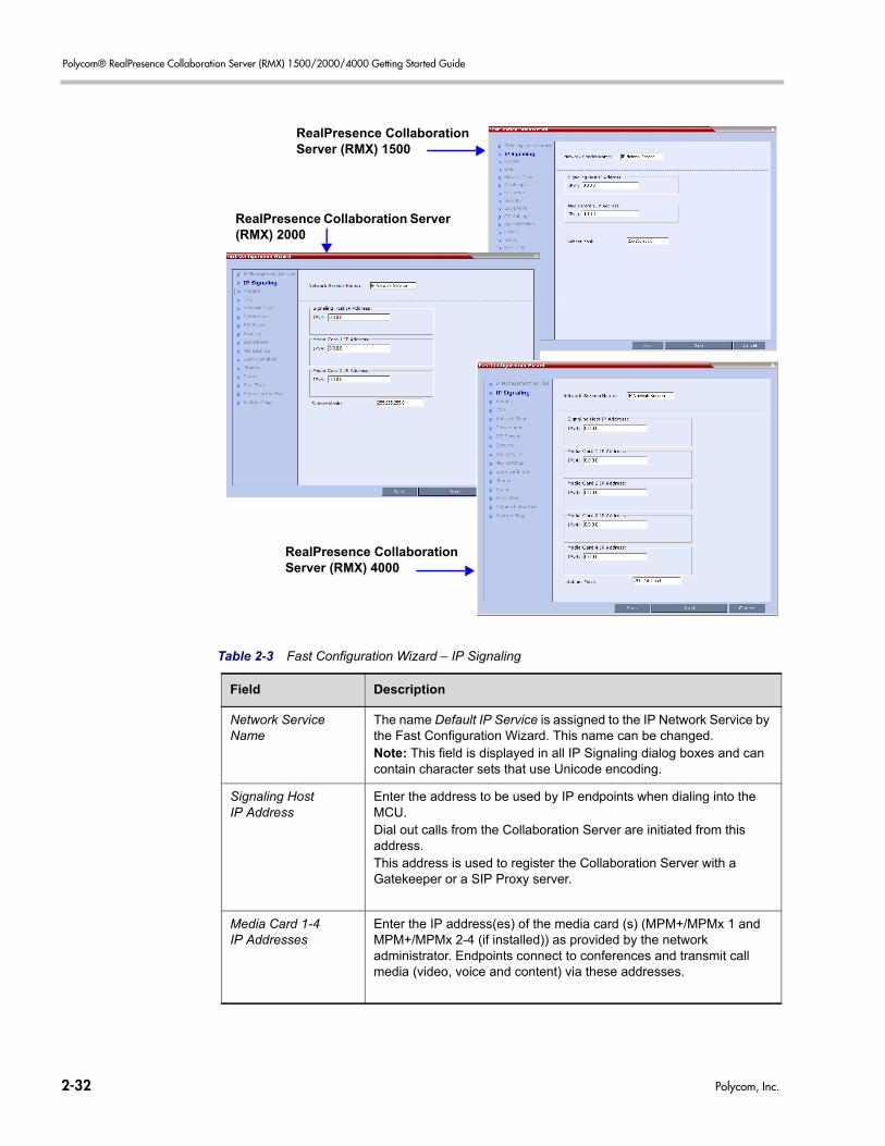
Polycom® RealPresence Collaboration Server (RMX) 1500/2000/4000 Getting Started Guide
RealPresence Collaboration Server (RMX) 1500
RealPresence Collaboration Server (RMX) 4000
RealPresence Collaboration Server (RMX) 2000
Table 2-3 Fast Configuration Wizard – IP Signaling
Field Description
Network Service Name
The name Default IP Service is assigned to the IP Network Service by the Fast Configuration Wizard. This name can be changed.Note: This field is displayed in all IP Signaling dialog boxes and can contain character sets that use Unicode encoding.
Signaling Host IP Address
Enter the address to be used by IP endpoints when dialing into the MCU.Dial out calls from the Collaboration Server are initiated from this address.This address is used to register the Collaboration Server with a Gatekeeper or a SIP Proxy server.
Media Card 1-4 IP Addresses
Enter the IP address(es) of the media card (s) (MPM+/MPMx 1 and MPM+/MPMx 2-4 (if installed)) as provided by the network administrator. Endpoints connect to conferences and transmit call media (video, voice and content) via these addresses.
2-32 Polycom, Inc.
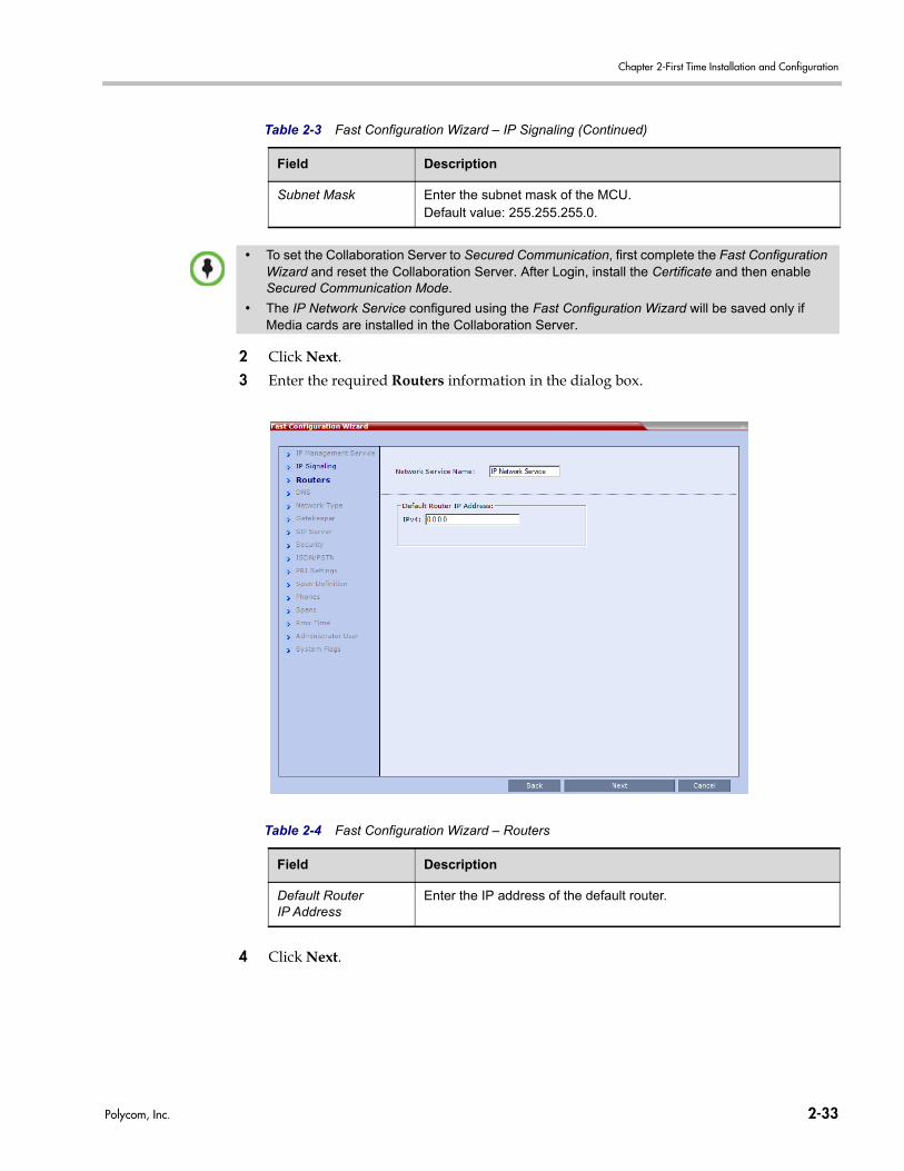
Chapter 2-First Time Installation and Configuration
2 Click Next.
3 Enter the required Routers information in the dialog box.
4 Click Next.
Subnet Mask Enter the subnet mask of the MCU. Default value: 255.255.255.0.
• To set the Collaboration Server to Secured Communication, first complete the Fast Configuration Wizard and reset the Collaboration Server. After Login, install the Certificate and then enable Secured Communication Mode.
• The IP Network Service configured using the Fast Configuration Wizard will be saved only if Media cards are installed in the Collaboration Server.
Table 2-3 Fast Configuration Wizard – IP Signaling (Continued)
Field Description
Table 2-4 Fast Configuration Wizard – Routers
Field Description
Default Router IP Address
Enter the IP address of the default router.
Polycom, Inc. 2-33
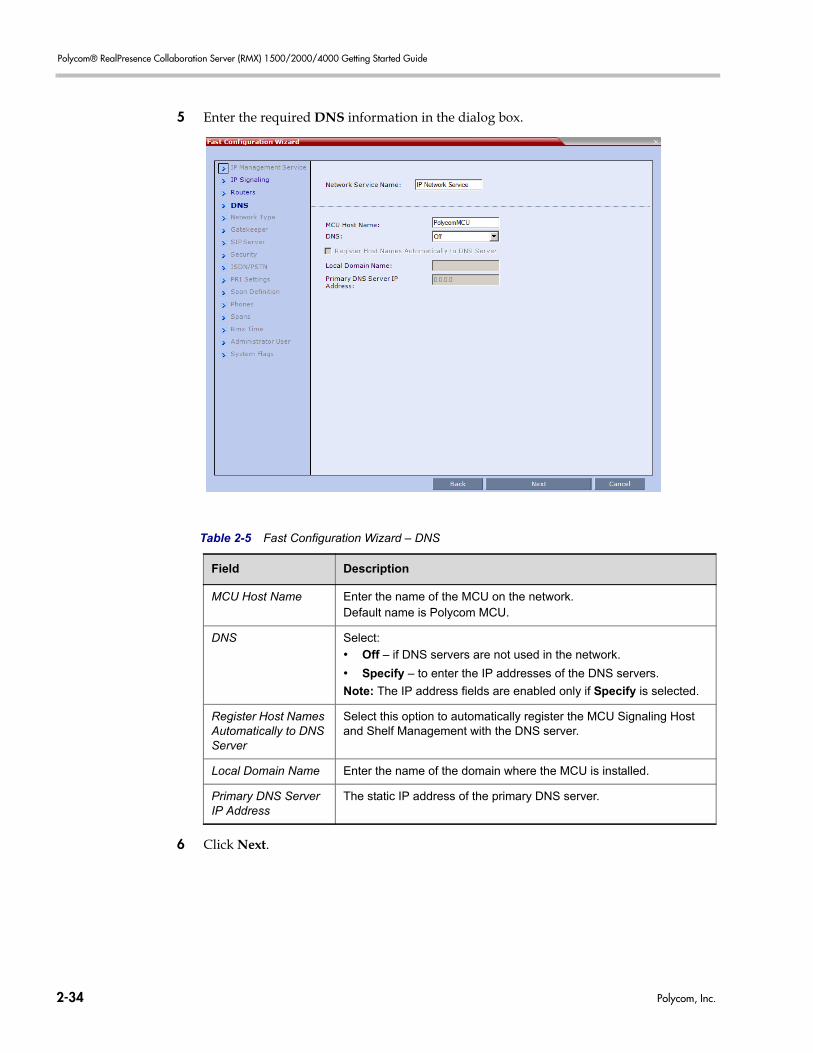
Polycom® RealPresence Collaboration Server (RMX) 1500/2000/4000 Getting Started Guide
5 Enter the required DNS information in the dialog box.
6 Click Next.
Table 2-5 Fast Configuration Wizard – DNS
Field Description
MCU Host Name Enter the name of the MCU on the network.Default name is Polycom MCU.
DNS Select:
• Off – if DNS servers are not used in the network.
• Specify – to enter the IP addresses of the DNS servers.
Note: The IP address fields are enabled only if Specify is selected.
Register Host Names Automatically to DNS Server
Select this option to automatically register the MCU Signaling Host and Shelf Management with the DNS server.
Local Domain Name Enter the name of the domain where the MCU is installed.
Primary DNS Server IP Address
The static IP address of the primary DNS server.
2-34 Polycom, Inc.
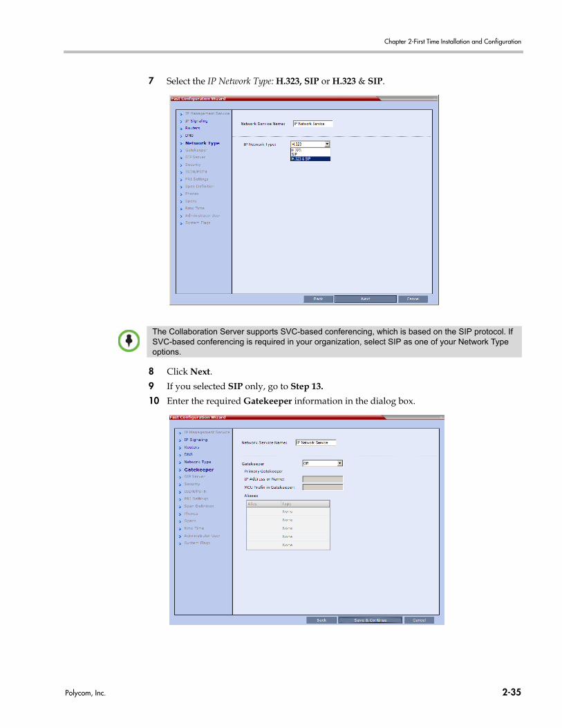
Chapter 2-First Time Installation and Configuration
7 Select the IP Network Type: H.323, SIP or H.323 & SIP.
8 Click Next.
9 If you selected SIP only, go to Step 13.
10 Enter the required Gatekeeper information in the dialog box.
The Collaboration Server supports SVC-based conferencing, which is based on the SIP protocol. If SVC-based conferencing is required in your organization, select SIP as one of your Network Type options.
Polycom, Inc. 2-35
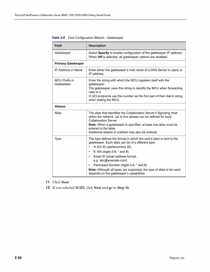
Polycom® RealPresence Collaboration Server (RMX) 1500/2000/4000 Getting Started Guide
11 Click Next.
12 If you selected H.323, click Next and go to Step 14.
Table 2-6 Fast Configuration Wizard – Gatekeeper
Field Description
Gatekeeper Select Specify to enable configuration of the gatekeeper IP address.When Off is selected, all gatekeeper options are disabled.
Primary Gatekeeper
IP Address or Name Enter either the gatekeeper’s host name (if a DNS Server is used) or IP address.
MCU Prefix in Gatekeeper
Enter the string with which the MCU registers itself with the gatekeeper.The gatekeeper uses this string to identify the MCU when forwarding calls to it. H.323 endpoints use this number as the first part of their dial-in string when dialing the MCU.
Aliases
Alias The alias that identifies the Collaboration Server’s Signaling Host within the network. Up to five aliases can be defined for each Collaboration Server.Note: When a gatekeeper is specified, at least one alias must be entered in the table.Additional aliases or prefixes may also be entered.
Type The type defines the format in which the card’s alias is sent to the gatekeeper. Each alias can be of a different type:
• H.323 ID (alphanumeric ID)
• E.164 (digits 0-9, * and #)
• Email ID (email address format, e.g. [email protected])
• Participant Number (digits 0-9, * and #)
Note: Although all types are supported, the type of alias to be used depends on the gatekeeper’s capabilities.
2-36 Polycom, Inc.
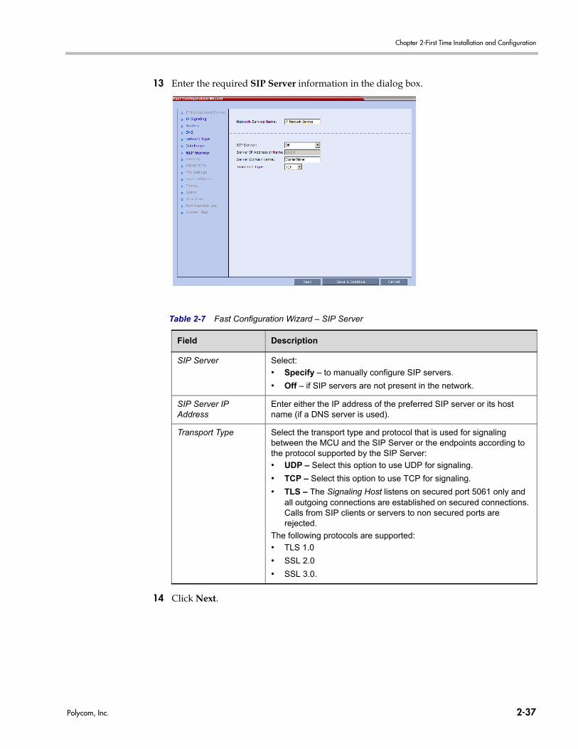
Chapter 2-First Time Installation and Configuration
13 Enter the required SIP Server information in the dialog box.
14 Click Next.
Table 2-7 Fast Configuration Wizard – SIP Server
Field Description
SIP Server Select:
• Specify – to manually configure SIP servers.
• Off – if SIP servers are not present in the network.
SIP Server IP Address
Enter either the IP address of the preferred SIP server or its host name (if a DNS server is used).
Transport Type Select the transport type and protocol that is used for signaling between the MCU and the SIP Server or the endpoints according to the protocol supported by the SIP Server:
• UDP – Select this option to use UDP for signaling.
• TCP – Select this option to use TCP for signaling.
• TLS – The Signaling Host listens on secured port 5061 only and all outgoing connections are established on secured connections. Calls from SIP clients or servers to non secured ports are rejected.
The following protocols are supported:
• TLS 1.0
• SSL 2.0
• SSL 3.0.
Polycom, Inc. 2-37
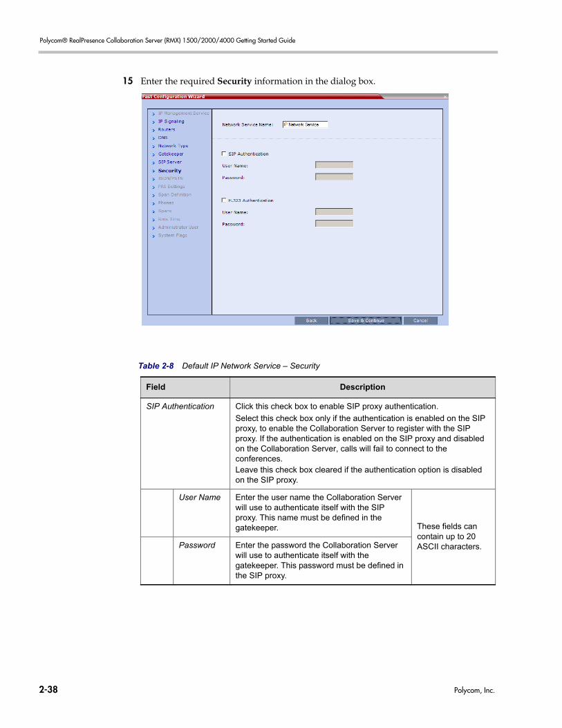
Polycom® RealPresence Collaboration Server (RMX) 1500/2000/4000 Getting Started Guide
15 Enter the required Security information in the dialog box.
Table 2-8 Default IP Network Service – Security
Field Description
SIP Authentication Click this check box to enable SIP proxy authentication.
Select this check box only if the authentication is enabled on the SIP proxy, to enable the Collaboration Server to register with the SIP proxy. If the authentication is enabled on the SIP proxy and disabled on the Collaboration Server, calls will fail to connect to the conferences.Leave this check box cleared if the authentication option is disabled on the SIP proxy.
User Name Enter the user name the Collaboration Server will use to authenticate itself with the SIP proxy. This name must be defined in the gatekeeper. These fields can
contain up to 20 ASCII characters.Password Enter the password the Collaboration Server
will use to authenticate itself with the gatekeeper. This password must be defined in the SIP proxy.
2-38 Polycom, Inc.
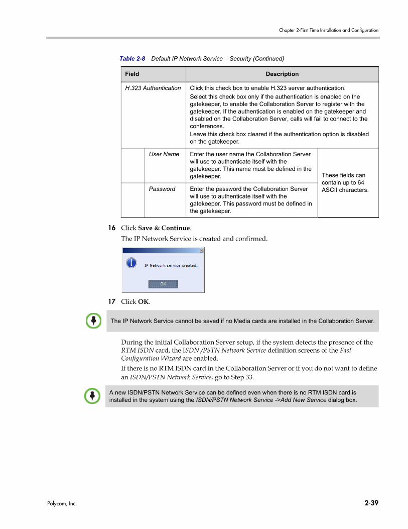
Chapter 2-First Time Installation and Configuration
16 Click Save & Continue.
The IP Network Service is created and confirmed.
17 Click OK.
During the initial Collaboration Server setup, if the system detects the presence of the RTM ISDN card, the ISDN /PSTN Network Service definition screens of the Fast Configuration Wizard are enabled.If there is no RTM ISDN card in the Collaboration Server or if you do not want to define an ISDN/PSTN Network Service, go to Step 33.
H.323 Authentication Click this check box to enable H.323 server authentication.
Select this check box only if the authentication is enabled on the gatekeeper, to enable the Collaboration Server to register with the gatekeeper. If the authentication is enabled on the gatekeeper and disabled on the Collaboration Server, calls will fail to connect to the conferences.Leave this check box cleared if the authentication option is disabled on the gatekeeper.
User Name Enter the user name the Collaboration Server will use to authenticate itself with the gatekeeper. This name must be defined in the gatekeeper. These fields can
contain up to 64 ASCII characters.Password Enter the password the Collaboration Server
will use to authenticate itself with the gatekeeper. This password must be defined in the gatekeeper.
Table 2-8 Default IP Network Service – Security (Continued)
Field Description
The IP Network Service cannot be saved if no Media cards are installed in the Collaboration Server.
A new ISDN/PSTN Network Service can be defined even when there is no RTM ISDN card is installed in the system using the ISDN/PSTN Network Service ->Add New Service dialog box.
Polycom, Inc. 2-39
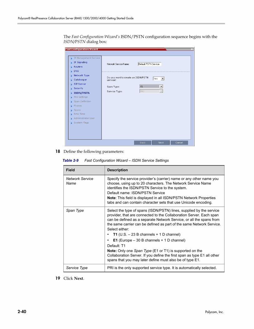
Polycom® RealPresence Collaboration Server (RMX) 1500/2000/4000 Getting Started Guide
The Fast Configuration Wizard’s ISDN/PSTN configuration sequence begins with the ISDN/PSTN dialog box:
18 Define the following parameters:
19 Click Next.
Table 2-9 Fast Configuration Wizard – ISDN Service Settings
Field Description
Network Service Name
Specify the service provider’s (carrier) name or any other name you choose, using up to 20 characters. The Network Service Name identifies the ISDN/PSTN Service to the system.Default name: ISDN/PSTN ServiceNote: This field is displayed in all ISDN/PSTN Network Properties tabs and can contain character sets that use Unicode encoding.
Span Type Select the type of spans (ISDN/PSTN) lines, supplied by the service provider, that are connected to the Collaboration Server. Each span can be defined as a separate Network Service, or all the spans from the same carrier can be defined as part of the same Network Service. Select either:
• T1 (U.S. – 23 B channels + 1 D channel)
• E1 (Europe – 30 B channels + 1 D channel)
Default: T1Note: Only one Span Type (E1 or T1) is supported on the Collaboration Server. If you define the first span as type E1 all other spans that you may later define must also be of type E1.
Service Type PRI is the only supported service type. It is automatically selected.
2-40 Polycom, Inc.
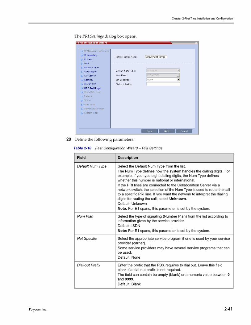
Chapter 2-First Time Installation and Configuration
The PRI Settings dialog box opens.
20 Define the following parameters:
Table 2-10 Fast Configuration Wizard – PRI Settings
Field Description
Default Num Type Select the Default Num Type from the list.The Num Type defines how the system handles the dialing digits. For example, if you type eight dialing digits, the Num Type defines whether this number is national or international. If the PRI lines are connected to the Collaboration Server via a network switch, the selection of the Num Type is used to route the call to a specific PRI line. If you want the network to interpret the dialing digits for routing the call, select Unknown.Default: UnknownNote: For E1 spans, this parameter is set by the system.
Num Plan Select the type of signaling (Number Plan) from the list according to information given by the service provider.Default: ISDNNote: For E1 spans, this parameter is set by the system.
Net Specific Select the appropriate service program if one is used by your service provider (carrier).Some service providers may have several service programs that can be used. Default: None
Dial-out Prefix Enter the prefix that the PBX requires to dial out. Leave this field blank if a dial-out prefix is not required.The field can contain be empty (blank) or a numeric value between 0 and 9999.Default: Blank
Polycom, Inc. 2-41
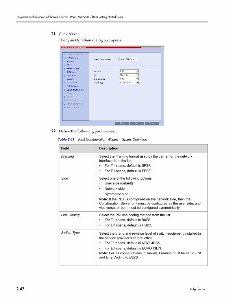
Polycom® RealPresence Collaboration Server (RMX) 1500/2000/4000 Getting Started Guide
21 Click Next.
The Span Definition dialog box opens.
22 Define the following parameters:
Table 2-11 Fast Configuration Wizard – Spans Definition
Field Description
Framing Select the Framing format used by the carrier for the network interface from the list.
• For T1 spans, default is SFSF.
• For E1 spans, default is FEBE.
Side Select one of the following options:
• User side (default)
• Network side
• Symmetric side
Note: If the PBX is configured on the network side, then the Collaboration Server unit must be configured as the user side, and vice versa, or both must be configured symmetrically.
Line Coding Select the PRI line coding method from the list.
• For T1 spans, default is B8ZS.
• For E1 spans, default is HDB3.
Switch Type Select the brand and revision level of switch equipment installed in the service provider’s central office.
• For T1 spans, default is AT&T 4ESS.
• For E1 spans, default is EURO ISDN.Note: For T1 configurations in Taiwan, Framing must be set to ESF and Line Coding to B8ZS.
2-42 Polycom, Inc.
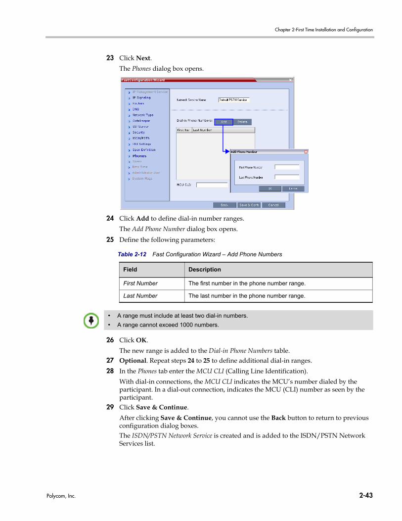
Chapter 2-First Time Installation and Configuration
23 Click Next.
The Phones dialog box opens.
24 Click Add to define dial-in number ranges.
The Add Phone Number dialog box opens.
25 Define the following parameters:
26 Click OK.
The new range is added to the Dial-in Phone Numbers table.27 Optional. Repeat steps 24 to 25 to define additional dial-in ranges.
28 In the Phones tab enter the MCU CLI (Calling Line Identification).
With dial-in connections, the MCU CLI indicates the MCU’s number dialed by the participant. In a dial-out connection, indicates the MCU (CLI) number as seen by the participant.
29 Click Save & Continue.
After clicking Save & Continue, you cannot use the Back button to return to previous configuration dialog boxes.The ISDN/PSTN Network Service is created and is added to the ISDN/PSTN Network Services list.
Table 2-12 Fast Configuration Wizard – Add Phone Numbers
Field Description
First Number The first number in the phone number range.
Last Number The last number in the phone number range.
• A range must include at least two dial-in numbers.
• A range cannot exceed 1000 numbers.
Polycom, Inc. 2-43
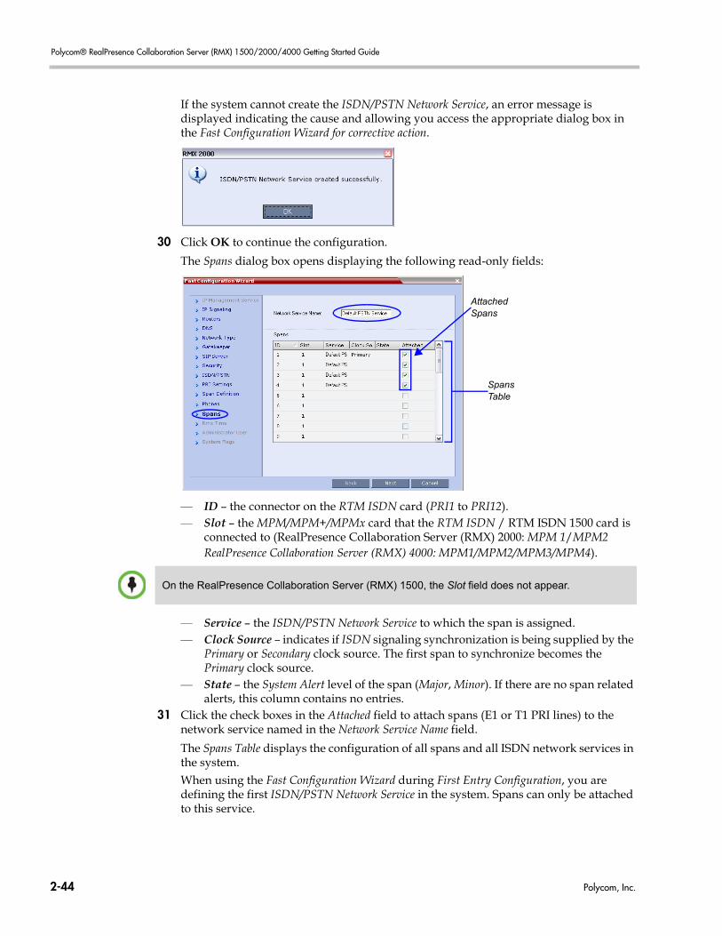
Polycom® RealPresence Collaboration Server (RMX) 1500/2000/4000 Getting Started Guide
If the system cannot create the ISDN/PSTN Network Service, an error message is displayed indicating the cause and allowing you access the appropriate dialog box in the Fast Configuration Wizard for corrective action.
30 Click OK to continue the configuration.
The Spans dialog box opens displaying the following read-only fields:
— ID – the connector on the RTM ISDN card (PRI1 to PRI12).— Slot – the MPM/MPM+/MPMx card that the RTM ISDN / RTM ISDN 1500 card is
connected to (RealPresence Collaboration Server (RMX) 2000: MPM 1/MPM2 RealPresence Collaboration Server (RMX) 4000: MPM1/MPM2/MPM3/MPM4).
— Service – the ISDN/PSTN Network Service to which the span is assigned.— Clock Source – indicates if ISDN signaling synchronization is being supplied by the
Primary or Secondary clock source. The first span to synchronize becomes the Primary clock source.
— State – the System Alert level of the span (Major, Minor). If there are no span related alerts, this column contains no entries.
31 Click the check boxes in the Attached field to attach spans (E1 or T1 PRI lines) to the network service named in the Network Service Name field.
The Spans Table displays the configuration of all spans and all ISDN network services in the system.When using the Fast Configuration Wizard during First Entry Configuration, you are defining the first ISDN/PSTN Network Service in the system. Spans can only be attached to this service.
SpansTable
AttachedSpans
On the RealPresence Collaboration Server (RMX) 1500, the Slot field does not appear.
2-44 Polycom, Inc.
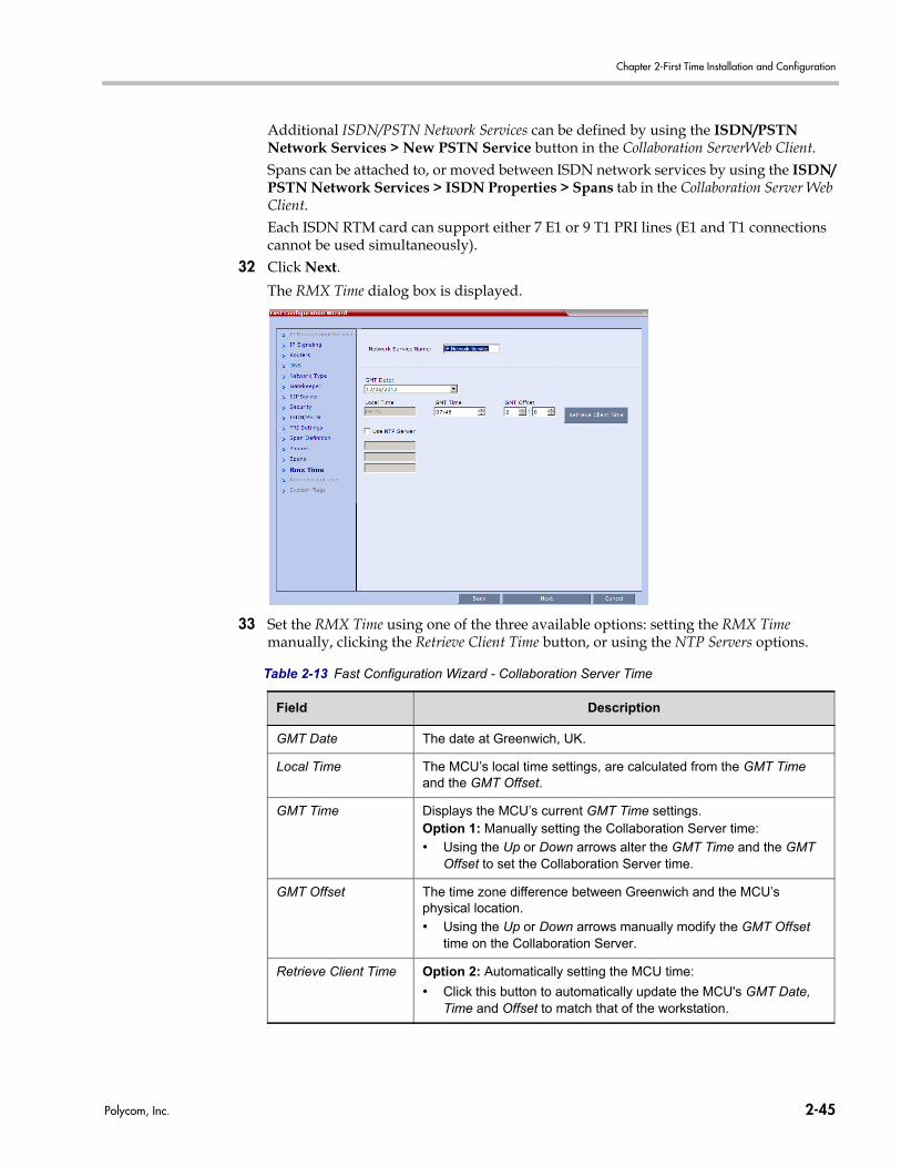
Chapter 2-First Time Installation and Configuration
Additional ISDN/PSTN Network Services can be defined by using the ISDN/PSTN Network Services > New PSTN Service button in the Collaboration ServerWeb Client.Spans can be attached to, or moved between ISDN network services by using the ISDN/PSTN Network Services > ISDN Properties > Spans tab in the Collaboration Server Web Client.Each ISDN RTM card can support either 7 E1 or 9 T1 PRI lines (E1 and T1 connections cannot be used simultaneously).
32 Click Next.
The RMX Time dialog box is displayed.
33 Set the RMX Time using one of the three available options: setting the RMX Time manually, clicking the Retrieve Client Time button, or using the NTP Servers options.
Table 2-13 Fast Configuration Wizard - Collaboration Server Time
Field Description
GMT Date The date at Greenwich, UK.
Local Time The MCU’s local time settings, are calculated from the GMT Time and the GMT Offset.
GMT Time Displays the MCU’s current GMT Time settings.Option 1: Manually setting the Collaboration Server time:
• Using the Up or Down arrows alter the GMT Time and the GMT Offset to set the Collaboration Server time.
GMT Offset The time zone difference between Greenwich and the MCU’s physical location.
• Using the Up or Down arrows manually modify the GMT Offset time on the Collaboration Server.
Retrieve Client Time Option 2: Automatically setting the MCU time:
• Click this button to automatically update the MCU's GMT Date, Time and Offset to match that of the workstation.
Polycom, Inc. 2-45
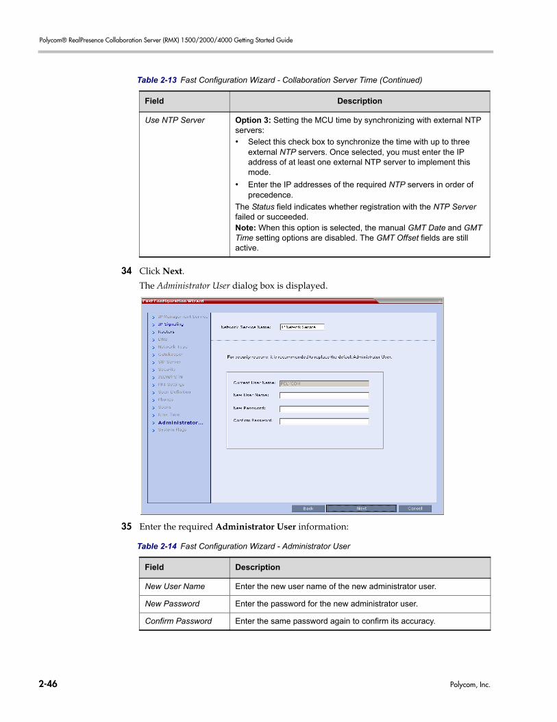
Polycom® RealPresence Collaboration Server (RMX) 1500/2000/4000 Getting Started Guide
34 Click Next.
The Administrator User dialog box is displayed.
35 Enter the required Administrator User information:
Use NTP Server Option 3: Setting the MCU time by synchronizing with external NTP servers:
• Select this check box to synchronize the time with up to three external NTP servers. Once selected, you must enter the IP address of at least one external NTP server to implement this mode.
• Enter the IP addresses of the required NTP servers in order of precedence.
The Status field indicates whether registration with the NTP Server failed or succeeded.Note: When this option is selected, the manual GMT Date and GMT Time setting options are disabled. The GMT Offset fields are still active.
Table 2-13 Fast Configuration Wizard - Collaboration Server Time (Continued)
Field Description
Table 2-14 Fast Configuration Wizard - Administrator User
Field Description
New User Name Enter the new user name of the new administrator user.
New Password Enter the password for the new administrator user.
Confirm Password Enter the same password again to confirm its accuracy.
2-46 Polycom, Inc.
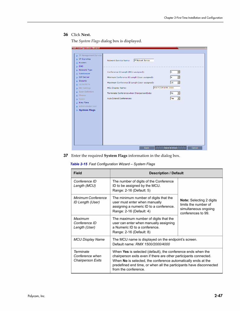
Chapter 2-First Time Installation and Configuration
36 Click Next.
The System Flags dialog box is displayed.
37 Enter the required System Flags information in the dialog box.
Table 2-15 Fast Configuration Wizard – System Flags
Field Description / Default
Conference ID Length (MCU)
The number of digits of the Conference ID to be assigned by the MCU.Range: 2-16 (Default: 5)
Note: Selecting 2 digits limits the number of simultaneous ongoing conferences to 99.
Minimum Conference ID Length (User)
The minimum number of digits that the user must enter when manually assigning a numeric ID to a conference. Range: 2-16 (Default: 4)
Maximum Conference ID Length (User)
The maximum number of digits that the user can enter when manually assigning a Numeric ID to a conference. Range: 2-16 (Default: 8)
MCU Display Name The MCU name is displayed on the endpoint’s screen.Default name: RMX 1500/2000/4000
Terminate Conference when Chairperson Exits
When Yes is selected (default), the conference ends when the chairperson exits even if there are other participants connected.When No is selected, the conference automatically ends at the predefined end time, or when all the participants have disconnected from the conference.
Polycom, Inc. 2-47
Polycom® RealPresence Collaboration Server (RMX) 1500/2000/4000 Getting Started Guide
These flags can be modified later, if required, by selecting the System Configuration option from the Setup menu. For more information, see the RealPresence Collaboration Server (RMX) 1500/2000/4000 Administrator’s Guide, "Modifying System Flags” on page 21-1.
38 Click Save & Close.
The system confirms successful configuration.39 In the Success Message box, click OK.
40 In the Reset Confirmation dialog box, click Yes.
41 In the Please wait for system reset message box, click OK.
42 Refresh the browser periodically until the Login screen is displayed.
43 When the Login screen is displayed, enter your Username and Password and click Login.In the Collaboration Server Web Client’s Main Screen an MCU State indicator
displays a progress indicator showing the time remaining until the system start-up is complete..The system is now fully configured and if there are no
other System Errors, the green READY/RDY LED (on the 2000/4000 the LEDs are on the CNTL module) turns ON and the ERROR/ERR LED is OFF.
Auto Extend Conferences
When Yes is selected (default), allows conferences running on the Collaboration Server to be automatically extended as long as there are participants connected and there are available resources. The maximum extension time allowed by the MCU is 30 minutes.
Table 2-15 Fast Configuration Wizard – System Flags (Continued)
Field Description / Default
System restart may take up to five minutes.
If the default User (POLYCOM) remains or the Collaboration Server time was not set, the active alarm is not deleted and the system status remains in Major. For system security reasons the system is not fully configured until the default user is deleted.
The Fast Configuration Wizard configures the Default IP Network Service with common parameters. Specific or additional settings (e.g. for ICE, or Secured Mode) should be performed once the initial configuration is complete. For detailed description of the IP Network Services, see the RealPresence Collaboration Server (RMX) 1500/2000/4000 Administrator’s Guide, Network Services.
2-48 Polycom, Inc.
Chapter 2-First Time Installation and Configuration
Selecting the Collaboration Server Web Client Languages
By default, the Collaboration Server Web Client interface is displayed only in English. However, the system administrator can choose the languages available for selection on the Login screen. These languages are represented by flags.
To choose the languages for selection in the Login screen:1 On the Collaboration Server menu, click Setup > Customized Display Settings >
Multilingual Setting.
2 Click the check boxes of the languages to appear in the Login screen of the Collaboration Server Web Client. For more information see the RealPresence Collaboration Server (RMX) 1500/2000/4000 Administrator’s Guide, "Multilingual Setting” on page 20-52.
If the selected language is not supported by the browser or the workstation’s Operating System, the Collaboration Server Web Client is displayed in English.
3 Click OK.
4 Log out and reconnect to the Collaboration Server. The Login screen will display the flags of the selected languages.
RealPresence Collaboration Server (RMX) 1500/2000/4000 Default Conferencing Settings
The Collaboration Server is shipped with default pre-configured conferencing entities set to CP (AVC) Conferencing Mode, which allow the MCU users and participants to start CP AVC ongoing conferences without further configuration.The default conferencing entities are:
Table 2-16 Default AVC-based Conferencing Entities
Entity Description
Meeting Rooms Conferences saved on the MCU without using resources. They are activated when the first participant dials in.There are four Meeting Rooms ready for use:Name IDMaple_Room 1001Oak_Room 1002Juniper_Room 1003Fig_Room 1004
Each Meeting Room uses the default Conference Profile called Factory_Video_Profile set to CP (AVC) Only Conferencing Mode, running at 384Kbps and has a default duration of one hour.
Polycom, Inc. 2-49
Polycom® RealPresence Collaboration Server (RMX) 1500/2000/4000 Getting Started Guide
Conference Profile Name: Factory_Video_ProfileA CP (AVC) Only Conference Profile is assigned to a Meeting Room to define its Conferencing Mode, conferencing parameters, such as line rate and video resolution.Factory_Video_Profile contains AVC video parameters with a bit rate of 384Kbps, Auto Layout and Polycom Skin. The Profile uses an IVR Service called Conference IVR Service.In addition to the default Conference Profile, the system is shipped with the following default Conference Profiles:
• Factory_SVC_Video_Profile - Contains the parameters of an SVC-based conference
Factory_Video_Profile - Contains the parameters of an AVC-CP only conference
Conference IVR Service Name: Conference IVR ServiceThe Conference IVR Service includes an optional video slide and all the voice messages played during the participant’s connection process and during the conference. The Conference IVR Service contains a set of voice prompts in English and an optional video slide.It automates the participant’s connection to a conference.
Entry Queue (AVC endpoints)
Name IDDefaultEQ 1000
Using an Entry Queue enables one dial-in number to be used for all AVC-based connections. In the Entry Queue, AVC participants are prompted for information to enable routing to their destination conferences.A default Entry Queue called DefaultEQ is provided.The default Entry Queue is also set to Ad Hoc conferencing which allows participants to start new conferences without prior definition by entering a Conference or Meeting Room ID that is not used by any ongoing conference currently running on the MCU. It uses an Entry Queue IVR Service called Entry Queue IVR Service.The default Welcome Slide displayed at the participants endpoint upon connection to the Entry Queue and lists the default Meeting Rooms. The participant can select one of these Meeting Rooms or enter another ID to start a new conference.If no Transit Entry Queue is defined, DefaultEQ is the default Transit Entry Queue. For more information see the RealPresence Collaboration Server (RMX) 1500/2000/4000 Administrator’s Guide, "Transit Entry Queue” on page 7-7.Note: An ISDN/PSTN dial-in number is not assigned to the Entry Queue as the number depends on the dial-in numbers range defined in the Network Service. It must be manually assigned to enable ISDN or PSTN participant connections to this Entry Queue. For more information, see the RealPresence Collaboration Server (RMX) 1500/2000/4000 Administrator’s Guide, "ISDN/PSTN Network Services” on page 16-44.
Table 2-16 Default AVC-based Conferencing Entities (Continued)
Entity Description
2-50 Polycom, Inc.
Chapter 2-First Time Installation and Configuration
Entry Queue IVR Service Name: Entry Queue IVR ServiceIncludes all the voice messages and video slides used to guide AVC participants though their connection process to the MCU and route them to their destination conference.Entry Queue IVR Service is the default Entry Queue IVR Service provided for the default Entry Queue.
Table 2-16 Default AVC-based Conferencing Entities (Continued)
Entity Description
Polycom, Inc. 2-51
Polycom® RealPresence Collaboration Server (RMX) 1500/2000/4000 Getting Started Guide
Customizing the RealPresence Collaboration Server (RMX) 1500/2000/4000 Default Conferencing Settings
You can customize the conferencing entities to your organization’s requirements:• To define SVC-based, Mixed CP and SVC or CP Only conferences, a new Conference
Profile must be created, setting the appropriate Conferencing Mode, the video parameters for the conference. This Profile can be used for defining new ongoing conferences and Meeting Rooms.For more information, see the RealPresence Collaboration Server (RMX) 1500/2000/4000 Administrator’s Guide, "Defining New Profiles” on page 2-25.
• To modify the properties of an existing CP AVC-based conference Profile, such as the conference line rate, specific video layout for the conference or the background that is used for the video display (skin), create a new Conference Profile. You can create a new CP AVC-based conference Profiles, to define additional conferencing parameters and video session types.This Profile can be used for defining new ongoing conferences, Meeting Rooms and Single-dial Entry Queues.For more information, see the RealPresence Collaboration Server (RMX) 1500/2000/4000 Administrator’s Guide, "Defining New Profiles” on page 2-25.
• To customize the Voice Prompts and Video Slides to different organizations, users, languages etc. – first record the required messages and create the video slides and then create the appropriate conference IVR Service or Entry Queue IVR Service.These services must be assigned to the appropriate conference profile or Entry Queue. For more information, see the RealPresence Collaboration Server (RMX) 1500/2000/4000 Administrator’s Guide, "IVR Services” on page 17-1.
• To allow ISDN participants to connect to a single dial Entry Queue a dial in number must be assigned to the pre-configured Entry Queue. To allow AVC participants to connect to a single dial Entry Queue at a line rate other than 384 Kbps (as in the default Entry Queue) or play voice messages in different languages – create a new Entry Queue.For more information, see the RealPresence Collaboration Server (RMX) 1500/2000/4000 Administrator’s Guide, "Defining a New Conference IVR Service” on page 17-6.
• You can personalize Meeting Rooms for people in your organization with predefined conference and chairperson passwords (for added security) and allow only authorized people to start on going conferences. For more information, see the RealPresence Collaboration Server (RMX) 1500/2000/4000 Administrator’s Guide, "Meeting Rooms” on page 6-1.
• To allow ISDN participants to connect directly to Meeting Rooms a dial in number must be assigned to the pre-configured Meeting Room.
• The conferencing entities are designed mainly for dial in participants without prior definition of participants. You can create your own Address Book containing a list of AVC participants to be dialed by the MCU. Once defined, these participants can be added to ongoing conferences saving the need to define them again.For more information, see the RealPresence Collaboration Server (RMX) 1500/2000/4000 Administrator’s Guide, "Address Book” on page 8-1.
• You can schedule conferences to start in the future. For more details, see the RealPresence Collaboration Server (RMX) 1500/2000/4000 Administrator’s Guide, "Reservations” on page 9-1.
2-52 Polycom, Inc.
3
Basic OperationThe MCU can be controlled using the Collaboration Server Web Client and the RMX Manager application. The most common operations performed via these applications are:• Starting, monitoring and managing conferences• Monitoring and managing participants and endpoints as individuals or groups.
— Participant – A person using an endpoint to connect to a conference. When using a Room System, several participants use a single endpoint.
— Endpoint – A hardware device, or set of devices, that can call, and be called by an MCU or another endpoint. For example, an endpoint can be a phone, a camera and microphone connected to a PC or an integrated Room System (conferencing system).
— Group – A group of participants or endpoints with a common name.
Starting the Collaboration Server Web ClientYou start the Collaboration Server Web Client by connecting to the MCU system. To connect to the MCU you need to get the following information from your system administrator:• User name• Password• MCU Control Unit IP Address
To start the Collaboration Server Web Client: 1 In your browser address line, enter http://<Control Unit IP Address> and press the
Enter key.
Polycom, Inc. 3-1
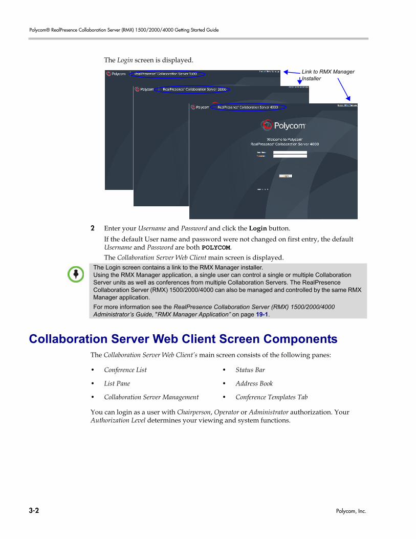
Polycom® RealPresence Collaboration Server (RMX) 1500/2000/4000 Getting Started Guide
The Login screen is displayed.
2 Enter your Username and Password and click the Login button.
If the default User name and password were not changed on first entry, the default Username and Password are both POLYCOM. The Collaboration Server Web Client main screen is displayed.
Collaboration Server Web Client Screen ComponentsThe Collaboration Server Web Client’s main screen consists of the following panes:
You can login as a user with Chairperson, Operator or Administrator authorization. Your Authorization Level determines your viewing and system functions.
Link to RMX Manager Installer
The Login screen contains a link to the RMX Manager installer. Using the RMX Manager application, a single user can control a single or multiple Collaboration Server units as well as conferences from multiple Collaboration Servers. The RealPresence Collaboration Server (RMX) 1500/2000/4000 can also be managed and controlled by the same RMX Manager application.
For more information see the RealPresence Collaboration Server (RMX) 1500/2000/4000 Administrator’s Guide, "RMX Manager Application” on page 19-1.
• Conference List • Status Bar
• List Pane • Address Book
• Collaboration Server Management • Conference Templates Tab
3-2 Polycom, Inc.
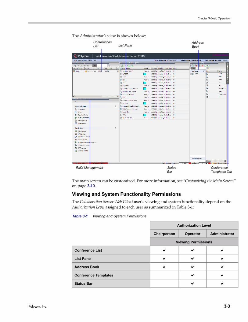
Chapter 3-Basic Operation
Po
The Administrator’s view is shown below:
The main screen can be customized. For more information, see "Customizing the Main Screen” on page 3-10.
Viewing and System Functionality Permissions
The Collaboration Server Web Client user’s viewing and system functionality depend on the Authorization Level assigned to each user as summarized in Table 3-1:
Table 3-1 Viewing and System Permissions
Authorization Level
Chairperson Operator Administrator
Viewing Permissions
Conference List
List Pane
Address Book
Conference Templates
Status Bar
ConferencesList List Pane
StatusBar
RMX Management
AddressBook
Conference Templates Tab
lycom, Inc. 3-3
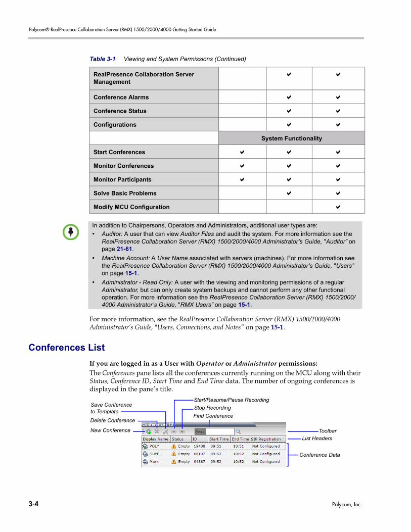
Polycom® RealPresence Collaboration Server (RMX) 1500/2000/4000 Getting Started Guide
For more information, see the RealPresence Collaboration Server (RMX) 1500/2000/4000 Administrator’s Guide, "Users, Connections, and Notes” on page 15-1.
Conferences List
If you are logged in as a User with Operator or Administrator permissions:The Conferences pane lists all the conferences currently running on the MCU along with their Status, Conference ID, Start Time and End Time data. The number of ongoing conferences is displayed in the pane’s title.
RealPresence Collaboration Server Management
Conference Alarms
Conference Status
Configurations
System Functionality
Start Conferences
Monitor Conferences
Monitor Participants
Solve Basic Problems
Modify MCU Configuration
Table 3-1 Viewing and System Permissions (Continued)
In addition to Chairpersons, Operators and Administrators, additional user types are:
• Auditor: A user that can view Auditor Files and audit the system. For more information see the RealPresence Collaboration Server (RMX) 1500/2000/4000 Administrator’s Guide, "Auditor” on page 21-61.
• Machine Account: A User Name associated with servers (machines). For more information see the RealPresence Collaboration Server (RMX) 1500/2000/4000 Administrator’s Guide, "Users” on page 15-1.
• Administrator - Read Only: A user with the viewing and monitoring permissions of a regular Administrator, but can only create system backups and cannot perform any other functional operation. For more information see the RealPresence Collaboration Server (RMX) 1500/2000/4000 Administrator’s Guide, "RMX Users” on page 15-1.
ToolbarList Headers
Conference Data
New Conference
Delete Conference
Stop Recording
Start/Resume/Pause RecordingSave Conferenceto Template
Find Conference
3-4 Polycom, Inc.
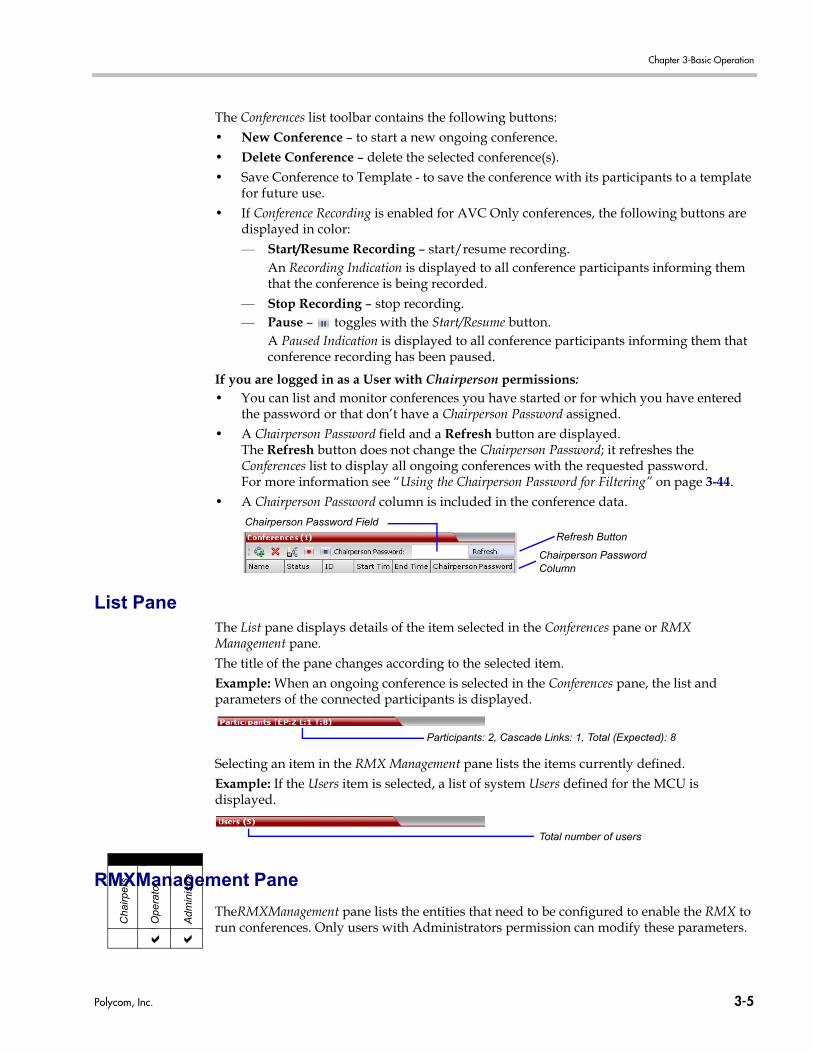
Chapter 3-Basic Operation
The Conferences list toolbar contains the following buttons:• New Conference – to start a new ongoing conference.• Delete Conference – delete the selected conference(s).• Save Conference to Template - to save the conference with its participants to a template
for future use.• If Conference Recording is enabled for AVC Only conferences, the following buttons are
displayed in color:— Start/Resume Recording – start/resume recording.
An Recording Indication is displayed to all conference participants informing them that the conference is being recorded.
— Stop Recording – stop recording.— Pause – toggles with the Start/Resume button.
A Paused Indication is displayed to all conference participants informing them that conference recording has been paused.
If you are logged in as a User with Chairperson permissions:• You can list and monitor conferences you have started or for which you have entered
the password or that don’t have a Chairperson Password assigned.• A Chairperson Password field and a Refresh button are displayed.
The Refresh button does not change the Chairperson Password; it refreshes the Conferences list to display all ongoing conferences with the requested password.For more information see “Using the Chairperson Password for Filtering” on page 3-44.
• A Chairperson Password column is included in the conference data.
List PaneThe List pane displays details of the item selected in the Conferences pane or RMX Management pane.The title of the pane changes according to the selected item.Example: When an ongoing conference is selected in the Conferences pane, the list and parameters of the connected participants is displayed.
Selecting an item in the RMX Management pane lists the items currently defined.Example: If the Users item is selected, a list of system Users defined for the MCU is displayed.
RMXManagement Pane
TheRMXManagement pane lists the entities that need to be configured to enable the RMX to run conferences. Only users with Administrators permission can modify these parameters.
Chairperson Password Field
Chairperson PasswordColumn
Refresh Button
Participants: 2, Cascade Links: 1, Total (Expected): 8
Total number of users
Viewing
Cha
irper
s
Adm
inis
tra
Op
erat
or
Polycom, Inc. 3-5
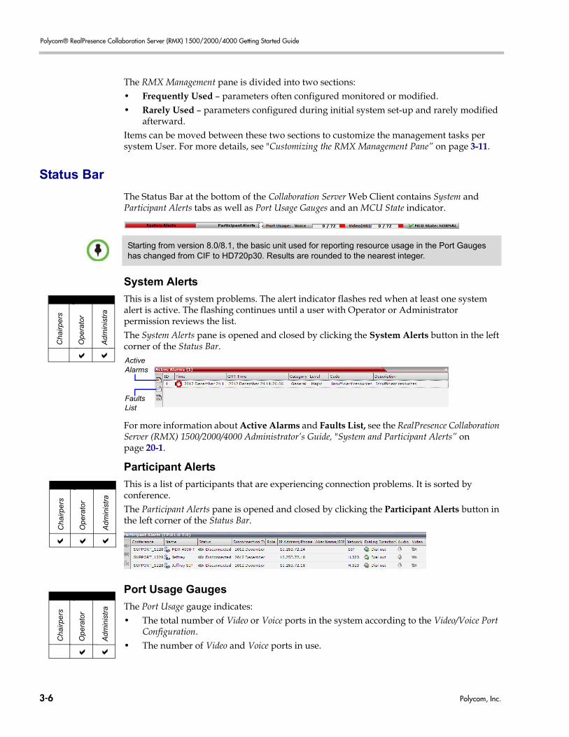
Polycom® RealPresence Collaboration Server (RMX) 1500/2000/4000 Getting Started Guide
The RMX Management pane is divided into two sections:• Frequently Used – parameters often configured monitored or modified. • Rarely Used – parameters configured during initial system set-up and rarely modified
afterward.Items can be moved between these two sections to customize the management tasks per system User. For more details, see "Customizing the RMX Management Pane” on page 3-11.
Status Bar
The Status Bar at the bottom of the Collaboration Server Web Client contains System and Participant Alerts tabs as well as Port Usage Gauges and an MCU State indicator.
System Alerts
This is a list of system problems. The alert indicator flashes red when at least one system alert is active. The flashing continues until a user with Operator or Administrator permission reviews the list.The System Alerts pane is opened and closed by clicking the System Alerts button in the left corner of the Status Bar.
For more information about Active Alarms and Faults List, see the RealPresence Collaboration Server (RMX) 1500/2000/4000 Administrator’s Guide, "System and Participant Alerts” on page 20-1.
Participant Alerts
This is a list of participants that are experiencing connection problems. It is sorted by conference.The Participant Alerts pane is opened and closed by clicking the Participant Alerts button in the left corner of the Status Bar.
Port Usage Gauges
The Port Usage gauge indicates:• The total number of Video or Voice ports in the system according to the Video/Voice Port
Configuration. • The number of Video and Voice ports in use.
Starting from version 8.0/8.1, the basic unit used for reporting resource usage in the Port Gauges has changed from CIF to HD720p30. Results are rounded to the nearest integer.
Viewing
Cha
irper
s
Ad
min
istr
a
Ope
rato
r
ActiveAlarms
FaultsList
Viewing
Cha
irper
s
Adm
inis
tra
Ope
rato
r
Viewing
Cha
irpe
rs
Adm
inis
tra
Ope
rato
r
3-6 Polycom, Inc.
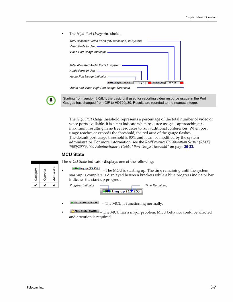
Chapter 3-Basic Operation
• The High Port Usage threshold.
The High Port Usage threshold represents a percentage of the total number of video or voice ports available. It is set to indicate when resource usage is approaching its maximum, resulting in no free resources to run additional conferences. When port usage reaches or exceeds the threshold, the red area of the gauge flashes. The default port usage threshold is 80% and it can be modified by the system administrator. For more information, see the RealPresence Collaboration Server (RMX) 1500/2000/4000 Administrator’s Guide, "Port Usage Threshold” on page 20-23.
MCU State
The MCU State indicator displays one of the following:
• – The MCU is starting up. The time remaining until the system start-up is complete is displayed between brackets while a blue progress indicator bar indicates the start-up progress.
• – The MCU is functioning normally.
• – The MCU has a major problem. MCU behavior could be affected and attention is required.
Audio Ports In Use
Total Allocated Audio Ports In System
Video Port Usage Indicator
Total Allocated Video Ports (HD resolution) In System
Video Ports In Use
Audio Port Usage Indicator
Audio and Video High Port Usage Threshold
Starting from version 8.0/8.1, the basic unit used for reporting video resource usage in the Port Gauges has changed from CIF to HD720p30. Results are rounded to the nearest integer.
Viewing
Cha
irpe
rs
Ad
min
istr
a
Ope
rato
r
Progress Indicator Time Remaining
Polycom, Inc. 3-7
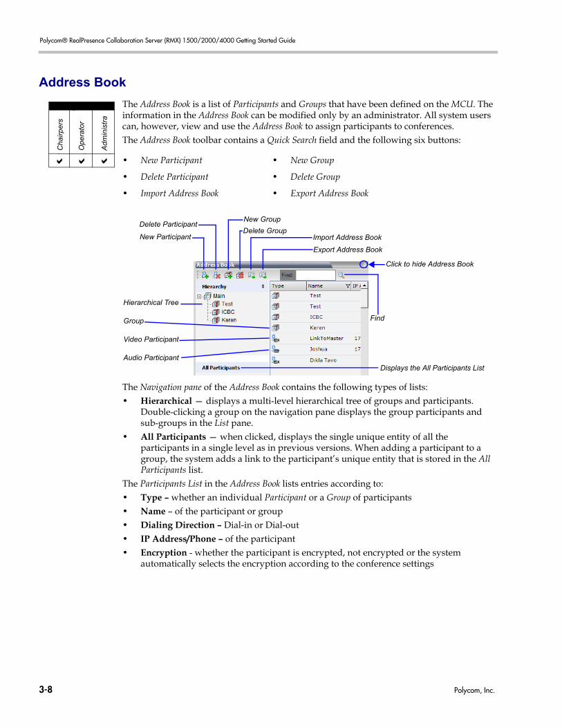
Polycom® RealPresence Collaboration Server (RMX) 1500/2000/4000 Getting Started Guide
Address Book
The Address Book is a list of Participants and Groups that have been defined on the MCU. The information in the Address Book can be modified only by an administrator. All system users can, however, view and use the Address Book to assign participants to conferences.The Address Book toolbar contains a Quick Search field and the following six buttons:
The Navigation pane of the Address Book contains the following types of lists:• Hierarchical — displays a multi-level hierarchical tree of groups and participants.
Double-clicking a group on the navigation pane displays the group participants and sub-groups in the List pane.
• All Participants — when clicked, displays the single unique entity of all the participants in a single level as in previous versions. When adding a participant to a group, the system adds a link to the participant’s unique entity that is stored in the All Participants list.
The Participants List in the Address Book lists entries according to:• Type – whether an individual Participant or a Group of participants• Name – of the participant or group• Dialing Direction – Dial-in or Dial-out• IP Address/Phone – of the participant• Encryption - whether the participant is encrypted, not encrypted or the system
automatically selects the encryption according to the conference settings
• New Participant • New Group
• Delete Participant • Delete Group
• Import Address Book • Export Address Book
Viewing
Cha
irper
s
Adm
inis
tra
Ope
rato
r
Hierarchical Tree
Group
Video Participant
Audio Participant
Delete GroupNew Participant Import Address Book
New Group
Export Address Book
Delete Participant
Click to hide Address Book
Find
Displays the All Participants List
3-8 Polycom, Inc.
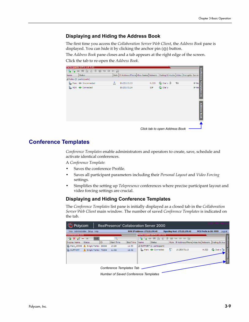
Chapter 3-Basic Operation
Displaying and Hiding the Address Book
The first time you access the Collaboration Server Web Client, the Address Book pane is displayed. You can hide it by clicking the anchor pin ( ) button.The Address Book pane closes and a tab appears at the right edge of the screen. Click the tab to re-open the Address Book.
Conference Templates
Conference Templates enable administrators and operators to create, save, schedule and activate identical conferences.A Conference Template:• Saves the conference Profile.• Saves all participant parameters including their Personal Layout and Video Forcing
settings.• Simplifies the setting up Telepresence conferences where precise participant layout and
video forcing settings are crucial.
Displaying and Hiding Conference Templates
The Conference Templates list pane is initially displayed as a closed tab in the Collaboration Server Web Client main window. The number of saved Conference Templates is indicated on the tab.
Click tab to open Address Book
Conference Templates Tab
Number of Saved Conference Templates
Polycom, Inc. 3-9
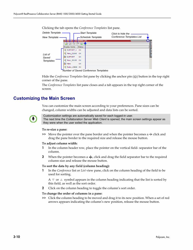
Polycom® RealPresence Collaboration Server (RMX) 1500/2000/4000 Getting Started Guide
Clicking the tab opens the Conference Templates list pane.
Hide the Conference Templates list pane by clicking the anchor pin ( ) button in the top right corner of the pane.The Conference Templates list pane closes and a tab appears in the top right corner of the screen.
Customizing the Main Screen
You can customize the main screen according to your preferences. Pane sizes can be changed, column widths can be adjusted and data lists can be sorted.
To re-size a pane:
>> Move the pointer over the pane border and when the pointer becomes a click and drag the pane border to the required size and release the mouse button.
To adjust column width:1 In the column header row, place the pointer on the vertical field- separator bar of the
column.
2 When the pointer becomes a , click and drag the field separator bar to the required column size and release the mouse button.
To sort the data by any field (column heading):1 In the Conference list or List view pane, click on the column heading of the field to be
used for sorting.
A or symbol appears in the column heading indicating that the list is sorted by this field, as well as the sort order.
2 Click on the column heading to toggle the column’s sort order.
To change the order of columns in a pane:>> Click the column heading to be moved and drag it to its new position. When a set of red
arrows appears indicating the column’s new position, release the mouse button.
New Template
Delete Template Start Template
Schedule Template
List of SavedTemplates
Click to hide theConference Templates List
Number of Saved Conference Templates
Customization settings are automatically saved for each logged-in user.The next time the Collaboration Server Web Client is opened, the main screen settings appear as they were when the user exited the application.
3-10 Polycom, Inc.
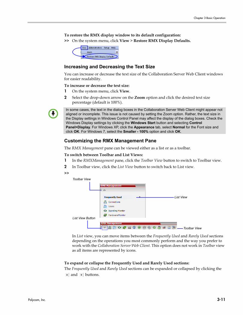
Chapter 3-Basic Operation
To restore the RMX display window to its default configuration:>> On the system menu, click View > Restore RMX Display Defaults.
Increasing and Decreasing the Text Size
You can increase or decrease the text size of the Collaboration Server Web Client windows for easier readability.
To increase or decrease the text size:1 On the system menu, click View.
2 Select the drop-down arrow on the Zoom option and click the desired text size percentage (default is 100%).
Customizing the RMX Management Pane
The RMX Management pane can be viewed either as a list or as a toolbar.
To switch between Toolbar and List Views:1 In the RMXManagement pane, click the Toolbar View button to switch to Toolbar view.
2 In Toolbar view, click the List View button to switch back to List view.
>>
In List view, you can move items between the Frequently Used and Rarely Used sections depending on the operations you most commonly perform and the way you prefer to work with the Collaboration Server Web Client. This option does not work in Toolbar view as all items are represented by icons.
To expand or collapse the Frequently Used and Rarely Used sections:The Frequently Used and Rarely Used sections can be expanded or collapsed by clicking the
and buttons.
In some cases, the text in the dialog boxes in the Collaboration Server Web Client might appear not aligned or incomplete. This issue is not caused by setting the Zoom option. Rather, the text size in the Display settings in Windows Control Panel may affect the display of the dialog boxes. Check the Windows Display settings by clicking the Windows Start button and selecting Control Panel>Display. For Windows XP, click the Appearance tab, select Normal for the Font size and click OK. For Windows 7, select the Smaller - 100% option and click OK.
Toolbar View
List View
Toolbar View
List View Button
Polycom, Inc. 3-11
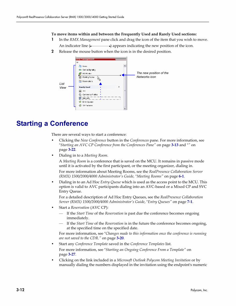
Polycom® RealPresence Collaboration Server (RMX) 1500/2000/4000 Getting Started Guide
To move items within and between the Frequently Used and Rarely Used sections:1 In the RMX Management pane click and drag the icon of the item that you wish to move.
An indicator line ( ) appears indicating the new position of the icon.2 Release the mouse button when the icon is in the desired position.
Starting a Conference
There are several ways to start a conference:• Clicking the New Conference button in the Conferences pane. For more information, see
"Starting an AVC CP Conference from the Conferences Pane” on page 3-13 and "” on page 3-22.
• Dialing in to a Meeting Room.A Meeting Room is a conference that is saved on the MCU. It remains in passive mode until it is activated by the first participant, or the meeting organizer, dialing in. For more information about Meeting Rooms, see the RealPresence Collaboration Server (RMX) 1500/2000/4000 Administrator’s Guide, "Meeting Rooms” on page 6-1.
• Dialing in to an Ad Hoc Entry Queue which is used as the access point to the MCU. This option is valid to AVC participants dialing into an AVC-based or a Mixed CP and SVC Entry Queue.For a detailed description of Ad Hoc Entry Queues, see the RealPresence Collaboration Server (RMX) 1500/2000/4000 Administrator’s Guide, "Entry Queues” on page 7-1.
• Start a Reservation (AVC CP):— If the Start Time of the Reservation is past due the conference becomes ongoing
immediately.— If the Start Time of the Reservation is in the future the conference becomes ongoing,
at the specified time on the specified date.For more information, see "Changes made to this information once the conference is running are not saved to the CDR.” on page 3-20.
• Start any Conference Template saved in the Conference Templates list.For more information, see "Starting an Ongoing Conference From a Template” on page 3-27.
• Clicking on the link included in a Microsoft Outlook Polycom Meeting Invitation or by manually dialing the numbers displayed in the invitation using the endpoint's numeric
The new position of the Networks icon
ListView
3-12 Polycom, Inc.
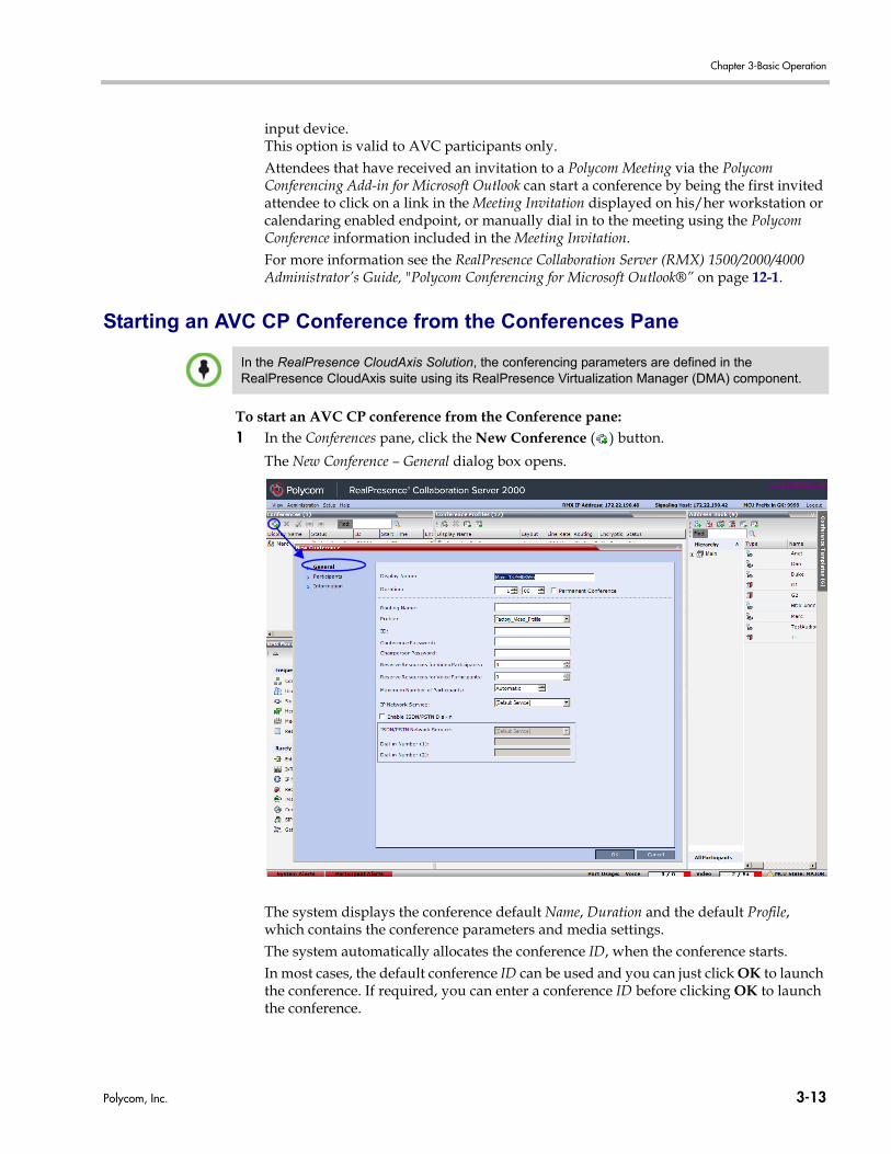
Chapter 3-Basic Operation
input device. This option is valid to AVC participants only.Attendees that have received an invitation to a Polycom Meeting via the Polycom Conferencing Add-in for Microsoft Outlook can start a conference by being the first invited attendee to click on a link in the Meeting Invitation displayed on his/her workstation or calendaring enabled endpoint, or manually dial in to the meeting using the Polycom Conference information included in the Meeting Invitation.For more information see the RealPresence Collaboration Server (RMX) 1500/2000/4000 Administrator’s Guide, "Polycom Conferencing for Microsoft Outlook®” on page 12-1.
Starting an AVC CP Conference from the Conferences Pane
To start an AVC CP conference from the Conference pane:1 In the Conferences pane, click the New Conference ( ) button.
The New Conference – General dialog box opens.
The system displays the conference default Name, Duration and the default Profile, which contains the conference parameters and media settings.The system automatically allocates the conference ID, when the conference starts.In most cases, the default conference ID can be used and you can just click OK to launch the conference. If required, you can enter a conference ID before clicking OK to launch the conference.
In the RealPresence CloudAxis Solution, the conferencing parameters are defined in the RealPresence CloudAxis suite using its RealPresence Virtualization Manager (DMA) component.
Polycom, Inc. 3-13
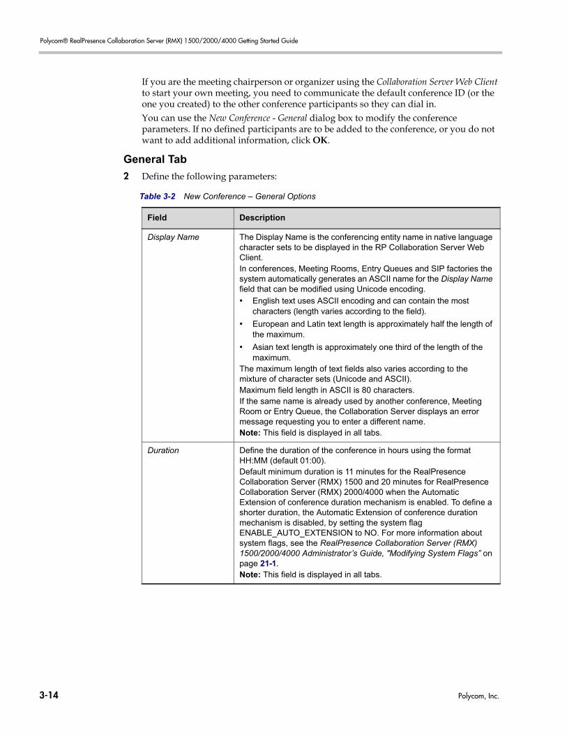
Polycom® RealPresence Collaboration Server (RMX) 1500/2000/4000 Getting Started Guide
If you are the meeting chairperson or organizer using the Collaboration Server Web Client to start your own meeting, you need to communicate the default conference ID (or the one you created) to the other conference participants so they can dial in.You can use the New Conference - General dialog box to modify the conference parameters. If no defined participants are to be added to the conference, or you do not want to add additional information, click OK.
General Tab
2 Define the following parameters:
Table 3-2 New Conference – General Options
Field Description
Display Name The Display Name is the conferencing entity name in native language character sets to be displayed in the RP Collaboration Server Web Client.In conferences, Meeting Rooms, Entry Queues and SIP factories the system automatically generates an ASCII name for the Display Name field that can be modified using Unicode encoding.
• English text uses ASCII encoding and can contain the most characters (length varies according to the field).
• European and Latin text length is approximately half the length of the maximum.
• Asian text length is approximately one third of the length of the maximum.
The maximum length of text fields also varies according to the mixture of character sets (Unicode and ASCII).Maximum field length in ASCII is 80 characters. If the same name is already used by another conference, Meeting Room or Entry Queue, the Collaboration Server displays an error message requesting you to enter a different name.Note: This field is displayed in all tabs.
Duration Define the duration of the conference in hours using the format HH:MM (default 01:00).Default minimum duration is 11 minutes for the RealPresence Collaboration Server (RMX) 1500 and 20 minutes for RealPresence Collaboration Server (RMX) 2000/4000 when the Automatic Extension of conference duration mechanism is enabled. To define a shorter duration, the Automatic Extension of conference duration mechanism is disabled, by setting the system flag ENABLE_AUTO_EXTENSION to NO. For more information about system flags, see the RealPresence Collaboration Server (RMX) 1500/2000/4000 Administrator’s Guide, "Modifying System Flags” on page 21-1.Note: This field is displayed in all tabs.
3-14 Polycom, Inc.
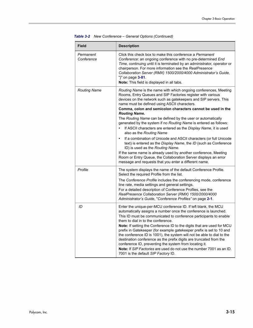
Chapter 3-Basic Operation
Permanent Conference
Click this check box to make this conference a Permanent Conference: an ongoing conference with no pre-determined End Time, continuing until it is terminated by an administrator, operator or chairperson. For more information see the RealPresence Collaboration Server (RMX) 1500/2000/4000 Administrator’s Guide, "]” on page 3-81.Note: This field is displayed in all tabs.
Routing Name Routing Name is the name with which ongoing conferences, Meeting Rooms, Entry Queues and SIP Factories register with various devices on the network such as gatekeepers and SIP servers. This name must be defined using ASCII characters.Comma, colon and semicolon characters cannot be used in the Routing Name.The Routing Name can be defined by the user or automatically generated by the system if no Routing Name is entered as follows:
• If ASCII characters are entered as the Display Name, it is used also as the Routing Name
• If a combination of Unicode and ASCII characters (or full Unicode text) is entered as the Display Name, the ID (such as Conference ID) is used as the Routing Name.
If the same name is already used by another conference, Meeting Room or Entry Queue, the Collaboration Server displays an error message and requests that you enter a different name.
Profile The system displays the name of the default Conference Profile. Select the required Profile from the list.
The Conference Profile includes the conferencing mode, conference line rate, media settings and general settings.For a detailed description of Conference Profiles, see the RealPresence Collaboration Server (RMX) 1500/2000/4000 Administrator’s Guide, "Conference Profiles” on page 2-1.
ID Enter the unique-per-MCU conference ID. If left blank, the MCU automatically assigns a number once the conference is launched. This ID must be communicated to conference participants to enable them to dial in to the conference.Note: If setting the Conference ID to the digits that are used for MCU prefix in Gatekeeper (for example gatekeeper prefix is set to 10 and the conference ID is 1001), the system will not be able to dial to the destination conference as the prefix digits are truncated from the conference ID, preventing the system from locating it.Note: If SIP Factories are used do not use the number 7001 as an ID. 7001 is the default SIP Factory ID.
Table 3-2 New Conference – General Options (Continued)
Field Description
Polycom, Inc. 3-15
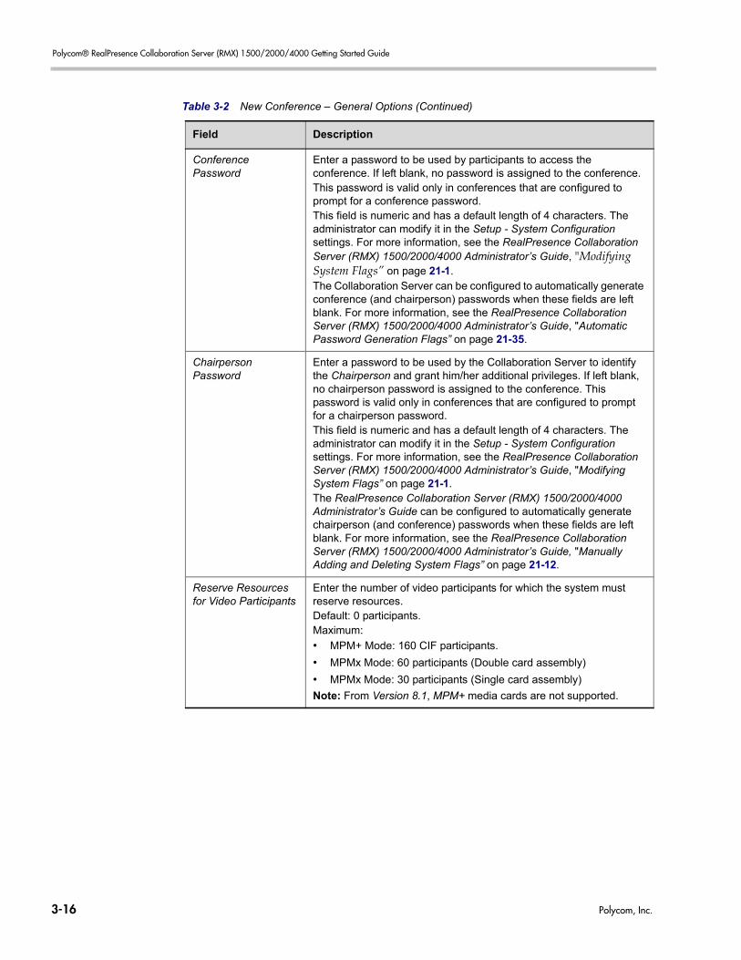
Polycom® RealPresence Collaboration Server (RMX) 1500/2000/4000 Getting Started Guide
Conference Password
Enter a password to be used by participants to access the conference. If left blank, no password is assigned to the conference. This password is valid only in conferences that are configured to prompt for a conference password. This field is numeric and has a default length of 4 characters. The administrator can modify it in the Setup - System Configuration settings. For more information, see the RealPresence Collaboration Server (RMX) 1500/2000/4000 Administrator’s Guide, "Modifying System Flags” on page 21-1.The Collaboration Server can be configured to automatically generate conference (and chairperson) passwords when these fields are left blank. For more information, see the RealPresence Collaboration Server (RMX) 1500/2000/4000 Administrator’s Guide, "Automatic Password Generation Flags” on page 21-35.
Chairperson Password
Enter a password to be used by the Collaboration Server to identify the Chairperson and grant him/her additional privileges. If left blank, no chairperson password is assigned to the conference. This password is valid only in conferences that are configured to prompt for a chairperson password.This field is numeric and has a default length of 4 characters. The administrator can modify it in the Setup - System Configuration settings. For more information, see the RealPresence Collaboration Server (RMX) 1500/2000/4000 Administrator’s Guide, "Modifying System Flags” on page 21-1.The RealPresence Collaboration Server (RMX) 1500/2000/4000 Administrator’s Guide can be configured to automatically generate chairperson (and conference) passwords when these fields are left blank. For more information, see the RealPresence Collaboration Server (RMX) 1500/2000/4000 Administrator’s Guide, "Manually Adding and Deleting System Flags” on page 21-12.
Reserve Resources for Video Participants
Enter the number of video participants for which the system must reserve resources.Default: 0 participants.Maximum:
• MPM+ Mode: 160 CIF participants.
• MPMx Mode: 60 participants (Double card assembly)
• MPMx Mode: 30 participants (Single card assembly)
Note: From Version 8.1, MPM+ media cards are not supported.
Table 3-2 New Conference – General Options (Continued)
Field Description
3-16 Polycom, Inc.
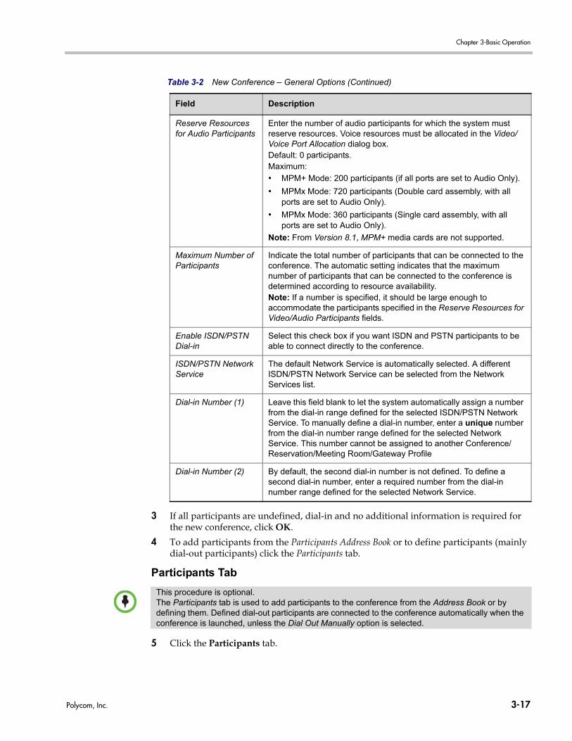
Chapter 3-Basic Operation
3 If all participants are undefined, dial-in and no additional information is required for the new conference, click OK.
4 To add participants from the Participants Address Book or to define participants (mainly dial-out participants) click the Participants tab.
Participants Tab
5 Click the Participants tab.
Reserve Resources for Audio Participants
Enter the number of audio participants for which the system must reserve resources. Voice resources must be allocated in the Video/Voice Port Allocation dialog box.Default: 0 participants.Maximum:
• MPM+ Mode: 200 participants (if all ports are set to Audio Only).
• MPMx Mode: 720 participants (Double card assembly, with all ports are set to Audio Only).
• MPMx Mode: 360 participants (Single card assembly, with all ports are set to Audio Only).
Note: From Version 8.1, MPM+ media cards are not supported.
Maximum Number of Participants
Indicate the total number of participants that can be connected to the conference. The automatic setting indicates that the maximum number of participants that can be connected to the conference is determined according to resource availability.Note: If a number is specified, it should be large enough to accommodate the participants specified in the Reserve Resources for Video/Audio Participants fields.
Enable ISDN/PSTN Dial-in
Select this check box if you want ISDN and PSTN participants to be able to connect directly to the conference.
ISDN/PSTN Network Service
The default Network Service is automatically selected. A different ISDN/PSTN Network Service can be selected from the Network Services list.
Dial-in Number (1) Leave this field blank to let the system automatically assign a number from the dial-in range defined for the selected ISDN/PSTN Network Service. To manually define a dial-in number, enter a unique number from the dial-in number range defined for the selected Network Service. This number cannot be assigned to another Conference/Reservation/Meeting Room/Gateway Profile
Dial-in Number (2) By default, the second dial-in number is not defined. To define a second dial-in number, enter a required number from the dial-in number range defined for the selected Network Service.
Table 3-2 New Conference – General Options (Continued)
Field Description
This procedure is optional.The Participants tab is used to add participants to the conference from the Address Book or by defining them. Defined dial-out participants are connected to the conference automatically when the conference is launched, unless the Dial Out Manually option is selected.
Polycom, Inc. 3-17
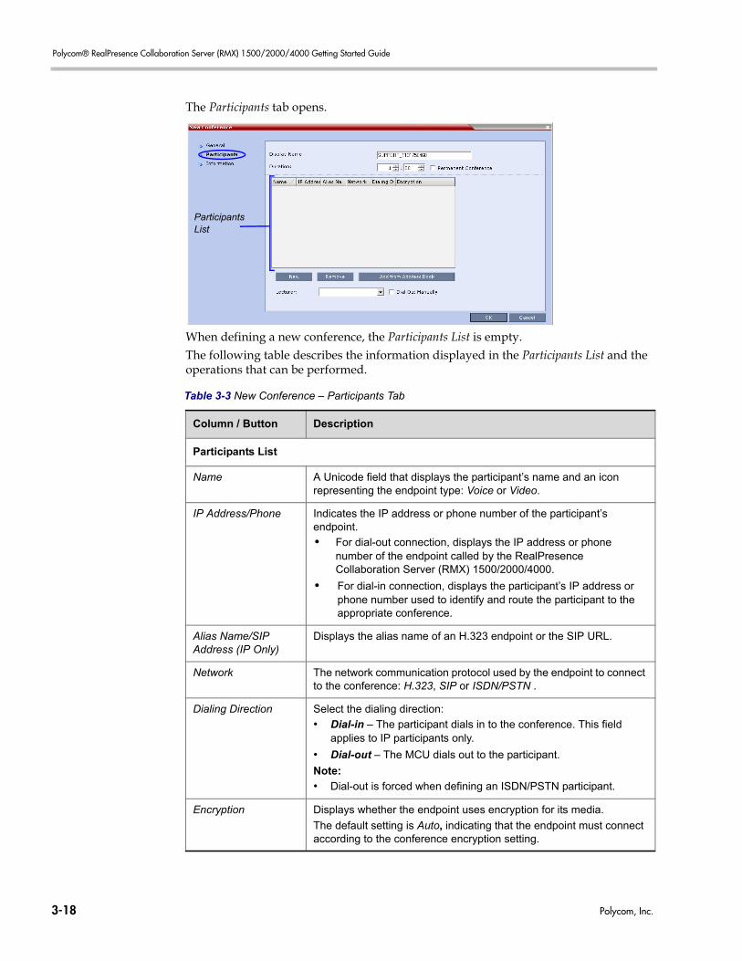
Polycom® RealPresence Collaboration Server (RMX) 1500/2000/4000 Getting Started Guide
The Participants tab opens.
When defining a new conference, the Participants List is empty.The following table describes the information displayed in the Participants List and the operations that can be performed.
Table 3-3 New Conference – Participants Tab
Column / Button Description
Participants List
Name A Unicode field that displays the participant’s name and an icon representing the endpoint type: Voice or Video.
IP Address/Phone Indicates the IP address or phone number of the participant’s endpoint.
• For dial-out connection, displays the IP address or phone number of the endpoint called by the RealPresence Collaboration Server (RMX) 1500/2000/4000.
• For dial-in connection, displays the participant’s IP address or phone number used to identify and route the participant to the appropriate conference.
Alias Name/SIP Address (IP Only)
Displays the alias name of an H.323 endpoint or the SIP URL.
Network The network communication protocol used by the endpoint to connect to the conference: H.323, SIP or ISDN/PSTN .
Dialing Direction Select the dialing direction:
• Dial-in – The participant dials in to the conference. This field applies to IP participants only.
• Dial-out – The MCU dials out to the participant.
Note:
• Dial-out is forced when defining an ISDN/PSTN participant.
Encryption Displays whether the endpoint uses encryption for its media.
The default setting is Auto, indicating that the endpoint must connect according to the conference encryption setting.
ParticipantsList
3-18 Polycom, Inc.
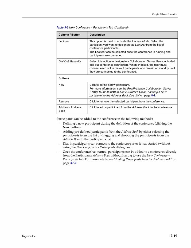
Chapter 3-Basic Operation
Participants can be added to the conference in the following methods:— Defining a new participant during the definition of the conference (clicking the
New button).— Adding pre-defined participants from the Address Book by either selecting the
participants from the list or dragging and dropping the participants from the Address Book to the Participants list.
— Dial-in participants can connect to the conference after it was started (without using the New Conference - Participants dialog box).
— Once the conference has started, participants can be added to a conference directly from the Participants Address Book without having to use the New Conference – Participants tab. For more details, see "Adding Participants from the Address Book” on page 3-55.
Lecturer This option is used to activate the Lecture Mode. Select the participant you want to designate as Lecturer from the list of conference participants.The Lecturer can be selected once the conference is running and participants are connected.
Dial Out Manually Select this option to designate a Collaboration Server User-controlled dial-out conference connection. When checked, the user must connect each of the dial-out participants who remain on standby until they are connected to the conference.
Buttons
New Click to define a new participant.For more information, see the RealPresence Collaboration Server (RMX) 1500/2000/4000 Administrator’s Guide, "Adding a New participant to the Address Book Directly” on page 8-7.
Remove Click to remove the selected participant from the conference.
Add from Address Book
Click to add a participant from the Address Book to the conference.
Table 3-3 New Conference – Participants Tab (Continued)
Column / Button Description
Polycom, Inc. 3-19
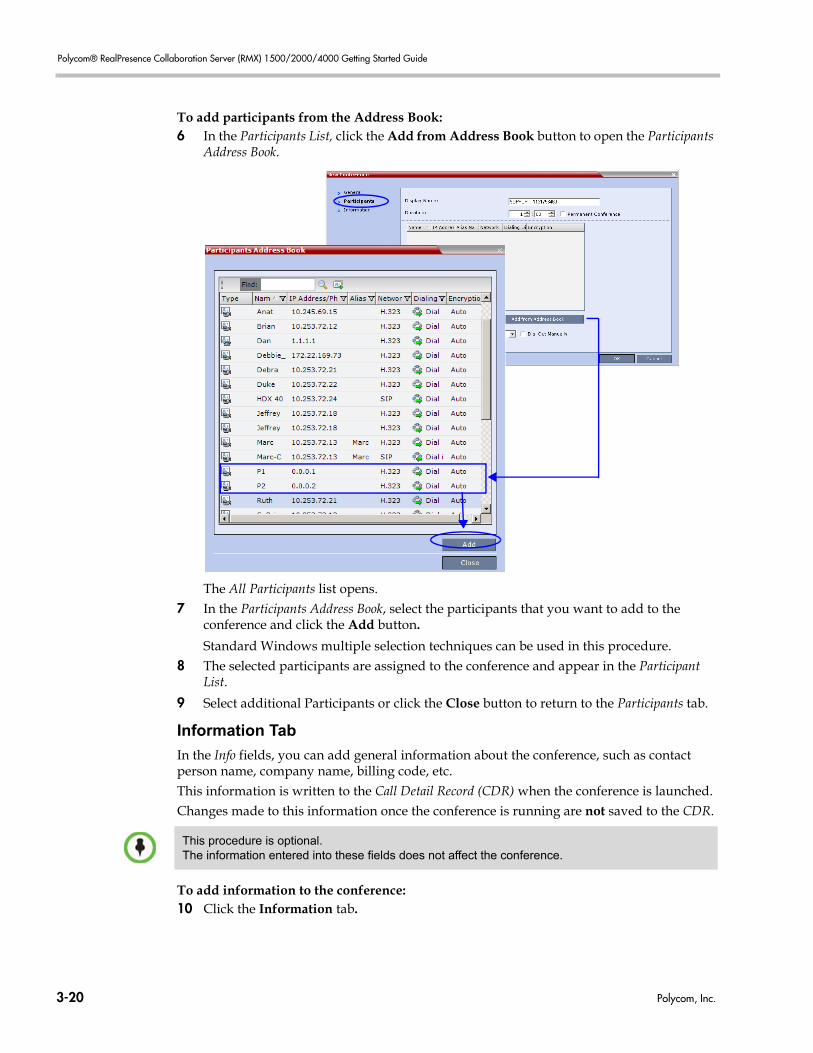
Polycom® RealPresence Collaboration Server (RMX) 1500/2000/4000 Getting Started Guide
To add participants from the Address Book:6 In the Participants List, click the Add from Address Book button to open the Participants
Address Book.
The All Participants list opens.7 In the Participants Address Book, select the participants that you want to add to the
conference and click the Add button.
Standard Windows multiple selection techniques can be used in this procedure.8 The selected participants are assigned to the conference and appear in the Participant
List.
9 Select additional Participants or click the Close button to return to the Participants tab.
Information Tab
In the Info fields, you can add general information about the conference, such as contact person name, company name, billing code, etc.This information is written to the Call Detail Record (CDR) when the conference is launched.Changes made to this information once the conference is running are not saved to the CDR.
To add information to the conference:10 Click the Information tab.
This procedure is optional.The information entered into these fields does not affect the conference.
3-20 Polycom, Inc.
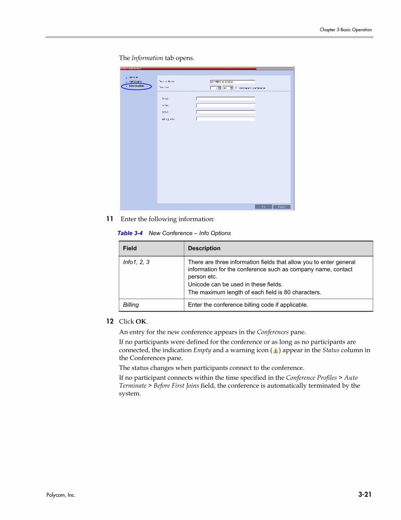
Chapter 3-Basic Operation
The Information tab opens.
11 Enter the following information:
12 Click OK.
An entry for the new conference appears in the Conferences pane.If no participants were defined for the conference or as long as no participants are connected, the indication Empty and a warning icon ( ) appear in the Status column in the Conferences pane.The status changes when participants connect to the conference.If no participant connects within the time specified in the Conference Profiles > Auto Terminate > Before First Joins field, the conference is automatically terminated by the system.
Table 3-4 New Conference – Info Options
Field Description
Info1, 2, 3 There are three information fields that allow you to enter general information for the conference such as company name, contact person etc. Unicode can be used in these fields. The maximum length of each field is 80 characters.
Billing Enter the conference billing code if applicable.
Polycom, Inc. 3-21
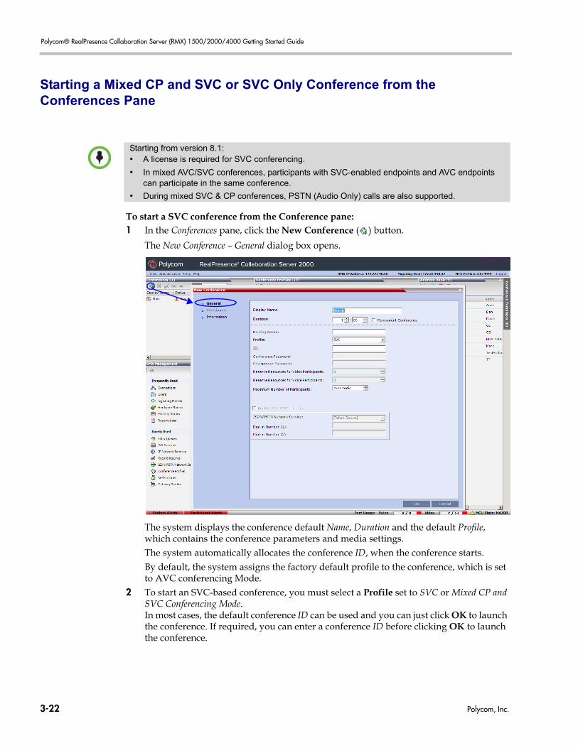
Polycom® RealPresence Collaboration Server (RMX) 1500/2000/4000 Getting Started Guide
Starting a Mixed CP and SVC or SVC Only Conference from the Conferences Pane
To start a SVC conference from the Conference pane:1 In the Conferences pane, click the New Conference ( ) button.
The New Conference – General dialog box opens.
The system displays the conference default Name, Duration and the default Profile, which contains the conference parameters and media settings.The system automatically allocates the conference ID, when the conference starts.By default, the system assigns the factory default profile to the conference, which is set to AVC conferencing Mode.
2 To start an SVC-based conference, you must select a Profile set to SVC or Mixed CP and SVC Conferencing Mode. In most cases, the default conference ID can be used and you can just click OK to launch the conference. If required, you can enter a conference ID before clicking OK to launch the conference.
Starting from version 8.1:• A license is required for SVC conferencing.
• In mixed AVC/SVC conferences, participants with SVC-enabled endpoints and AVC endpoints can participate in the same conference.
• During mixed SVC & CP conferences, PSTN (Audio Only) calls are also supported.
3-22 Polycom, Inc.
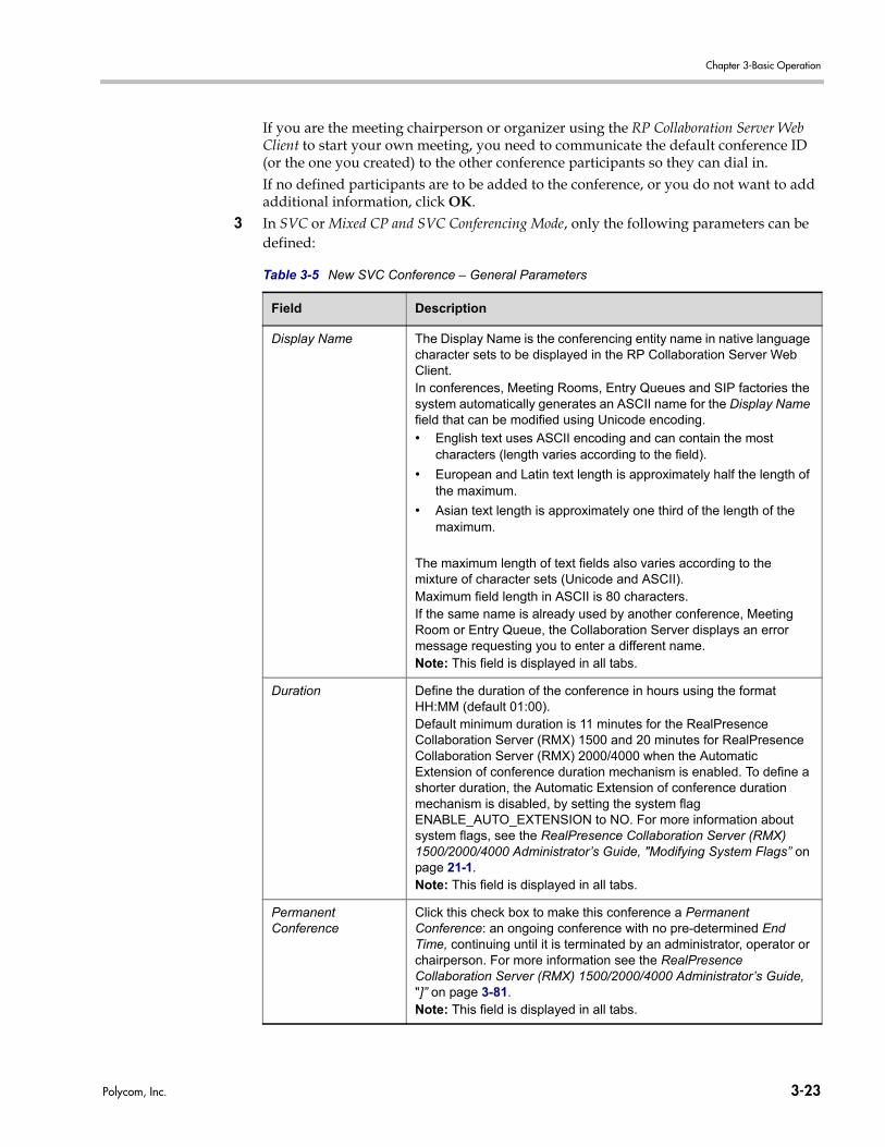
Chapter 3-Basic Operation
If you are the meeting chairperson or organizer using the RP Collaboration Server Web Client to start your own meeting, you need to communicate the default conference ID (or the one you created) to the other conference participants so they can dial in.If no defined participants are to be added to the conference, or you do not want to add additional information, click OK.
3 In SVC or Mixed CP and SVC Conferencing Mode, only the following parameters can be defined:
Table 3-5 New SVC Conference – General Parameters
Field Description
Display Name The Display Name is the conferencing entity name in native language character sets to be displayed in the RP Collaboration Server Web Client.In conferences, Meeting Rooms, Entry Queues and SIP factories the system automatically generates an ASCII name for the Display Name field that can be modified using Unicode encoding.
• English text uses ASCII encoding and can contain the most characters (length varies according to the field).
• European and Latin text length is approximately half the length of the maximum.
• Asian text length is approximately one third of the length of the maximum.
The maximum length of text fields also varies according to the mixture of character sets (Unicode and ASCII).Maximum field length in ASCII is 80 characters. If the same name is already used by another conference, Meeting Room or Entry Queue, the Collaboration Server displays an error message requesting you to enter a different name.Note: This field is displayed in all tabs.
Duration Define the duration of the conference in hours using the format HH:MM (default 01:00).Default minimum duration is 11 minutes for the RealPresence Collaboration Server (RMX) 1500 and 20 minutes for RealPresence Collaboration Server (RMX) 2000/4000 when the Automatic Extension of conference duration mechanism is enabled. To define a shorter duration, the Automatic Extension of conference duration mechanism is disabled, by setting the system flag ENABLE_AUTO_EXTENSION to NO. For more information about system flags, see the RealPresence Collaboration Server (RMX) 1500/2000/4000 Administrator’s Guide, "Modifying System Flags” on page 21-1.Note: This field is displayed in all tabs.
Permanent Conference
Click this check box to make this conference a Permanent Conference: an ongoing conference with no pre-determined End Time, continuing until it is terminated by an administrator, operator or chairperson. For more information see the RealPresence Collaboration Server (RMX) 1500/2000/4000 Administrator’s Guide, "]” on page 3-81.Note: This field is displayed in all tabs.
Polycom, Inc. 3-23
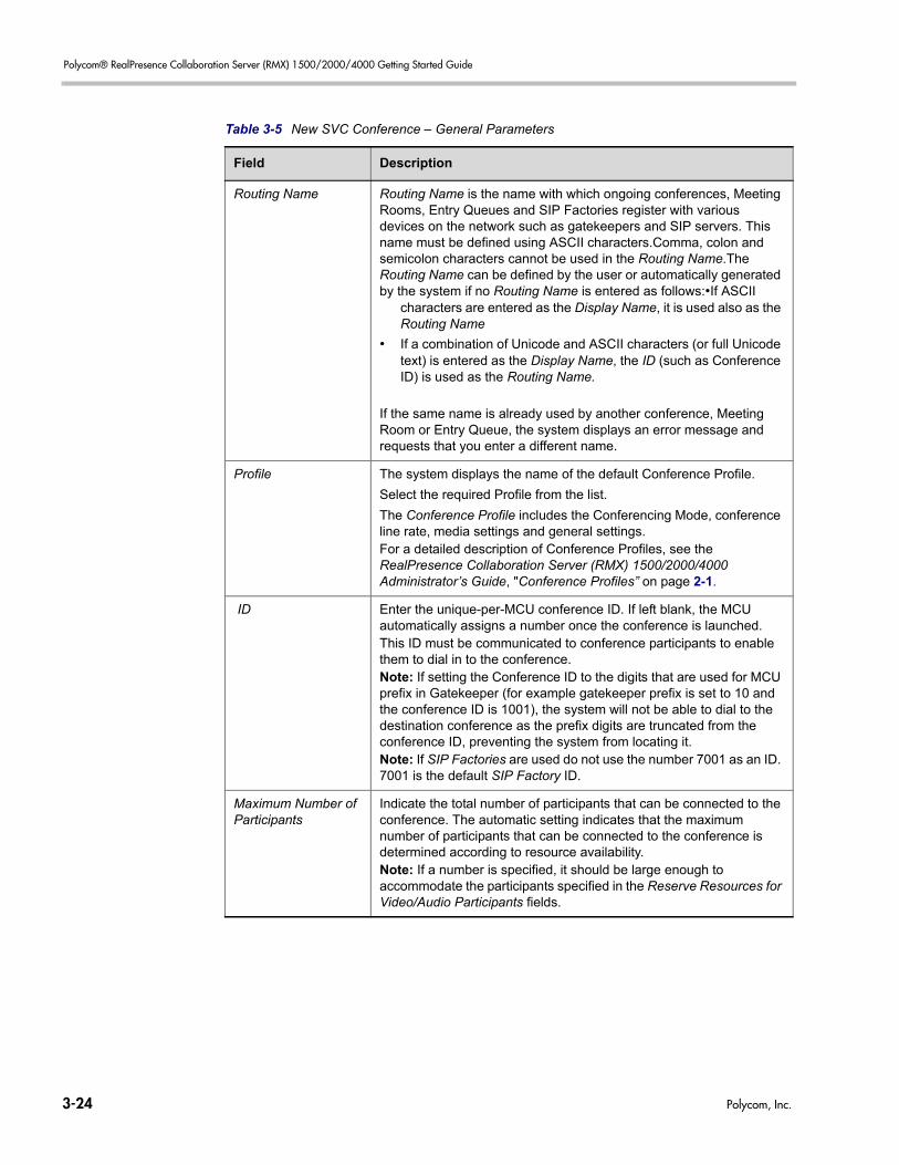
Polycom® RealPresence Collaboration Server (RMX) 1500/2000/4000 Getting Started Guide
Routing Name Routing Name is the name with which ongoing conferences, Meeting Rooms, Entry Queues and SIP Factories register with various devices on the network such as gatekeepers and SIP servers. This name must be defined using ASCII characters.Comma, colon and semicolon characters cannot be used in the Routing Name.The Routing Name can be defined by the user or automatically generated by the system if no Routing Name is entered as follows:•If ASCII
characters are entered as the Display Name, it is used also as the Routing Name
• If a combination of Unicode and ASCII characters (or full Unicode text) is entered as the Display Name, the ID (such as Conference ID) is used as the Routing Name.
If the same name is already used by another conference, Meeting Room or Entry Queue, the system displays an error message and requests that you enter a different name.
Profile The system displays the name of the default Conference Profile.
Select the required Profile from the list.
The Conference Profile includes the Conferencing Mode, conference line rate, media settings and general settings.For a detailed description of Conference Profiles, see the RealPresence Collaboration Server (RMX) 1500/2000/4000 Administrator’s Guide, "Conference Profiles” on page 2-1.
ID Enter the unique-per-MCU conference ID. If left blank, the MCU automatically assigns a number once the conference is launched. This ID must be communicated to conference participants to enable them to dial in to the conference.Note: If setting the Conference ID to the digits that are used for MCU prefix in Gatekeeper (for example gatekeeper prefix is set to 10 and the conference ID is 1001), the system will not be able to dial to the destination conference as the prefix digits are truncated from the conference ID, preventing the system from locating it.Note: If SIP Factories are used do not use the number 7001 as an ID. 7001 is the default SIP Factory ID.
Maximum Number of Participants
Indicate the total number of participants that can be connected to the conference. The automatic setting indicates that the maximum number of participants that can be connected to the conference is determined according to resource availability.Note: If a number is specified, it should be large enough to accommodate the participants specified in the Reserve Resources for Video/Audio Participants fields.
Table 3-5 New SVC Conference – General Parameters
Field Description
3-24 Polycom, Inc.
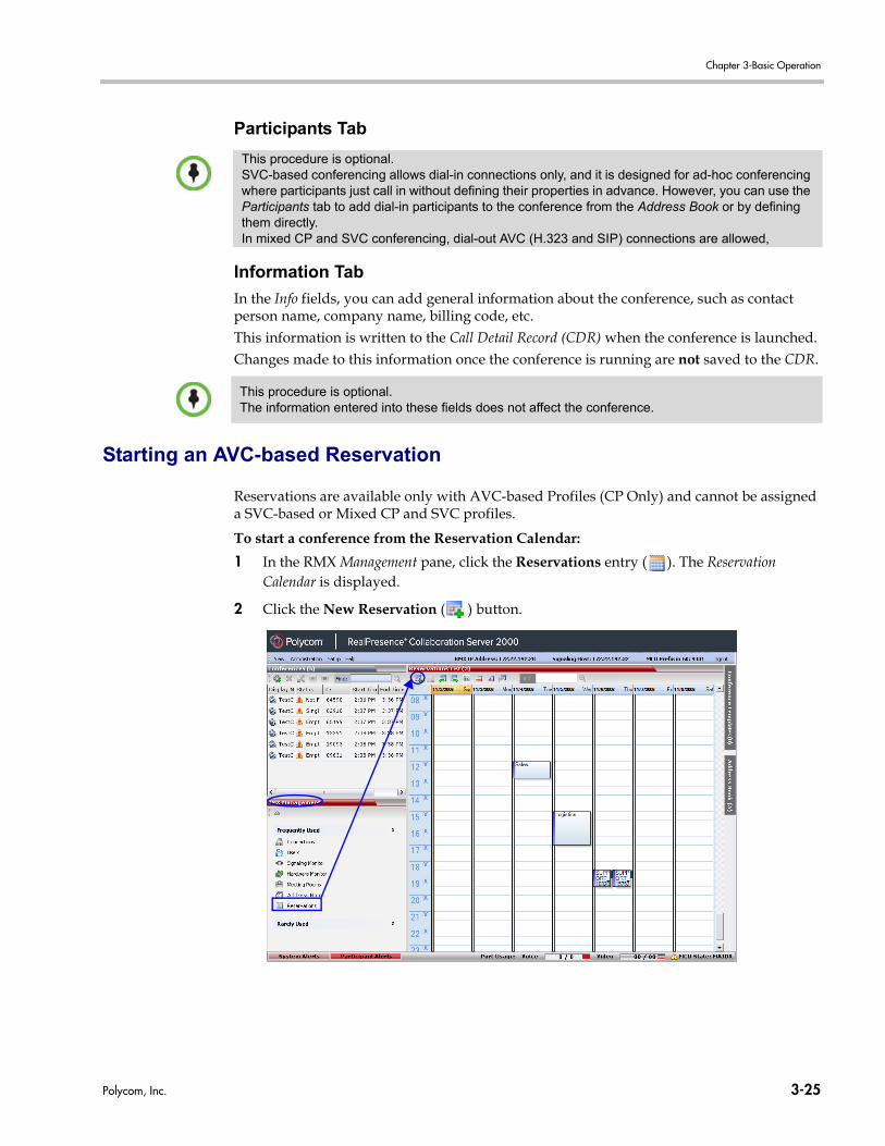
Chapter 3-Basic Operation
Participants Tab
Information Tab
In the Info fields, you can add general information about the conference, such as contact person name, company name, billing code, etc.This information is written to the Call Detail Record (CDR) when the conference is launched.Changes made to this information once the conference is running are not saved to the CDR.
Starting an AVC-based Reservation
Reservations are available only with AVC-based Profiles (CP Only) and cannot be assigned a SVC-based or Mixed CP and SVC profiles.
To start a conference from the Reservation Calendar:
1 In the RMX Management pane, click the Reservations entry ( ). The Reservation Calendar is displayed.
2 Click the New Reservation ( ) button.
This procedure is optional.SVC-based conferencing allows dial-in connections only, and it is designed for ad-hoc conferencing where participants just call in without defining their properties in advance. However, you can use the Participants tab to add dial-in participants to the conference from the Address Book or by defining them directly. In mixed CP and SVC conferencing, dial-out AVC (H.323 and SIP) connections are allowed,
This procedure is optional.The information entered into these fields does not affect the conference.
Polycom, Inc. 3-25
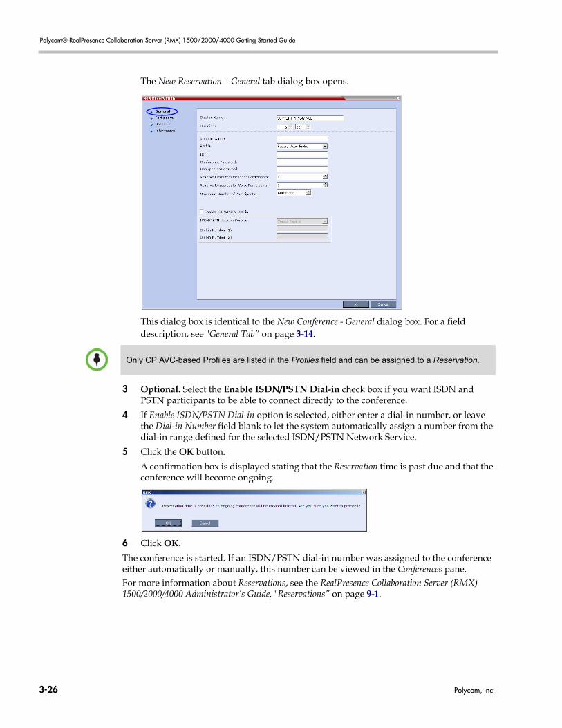
Polycom® RealPresence Collaboration Server (RMX) 1500/2000/4000 Getting Started Guide
The New Reservation – General tab dialog box opens.
This dialog box is identical to the New Conference - General dialog box. For a field description, see "General Tab” on page 3-14.
3 Optional. Select the Enable ISDN/PSTN Dial-in check box if you want ISDN and PSTN participants to be able to connect directly to the conference.
4 If Enable ISDN/PSTN Dial-in option is selected, either enter a dial-in number, or leave the Dial-in Number field blank to let the system automatically assign a number from the dial-in range defined for the selected ISDN/PSTN Network Service.
5 Click the OK button.
A confirmation box is displayed stating that the Reservation time is past due and that the conference will become ongoing.
6 Click OK.
The conference is started. If an ISDN/PSTN dial-in number was assigned to the conference either automatically or manually, this number can be viewed in the Conferences pane.For more information about Reservations, see the RealPresence Collaboration Server (RMX) 1500/2000/4000 Administrator’s Guide, "Reservations” on page 9-1.
Only CP AVC-based Profiles are listed in the Profiles field and can be assigned to a Reservation.
3-26 Polycom, Inc.
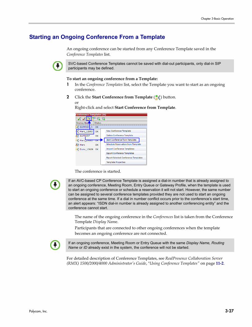
Chapter 3-Basic Operation
Starting an Ongoing Conference From a Template
An ongoing conference can be started from any Conference Template saved in the Conference Templates list.
To start an ongoing conference from a Template:1 In the Conference Templates list, select the Template you want to start as an ongoing
conference.
2 Click the Start Conference from Template ( ) button.orRight-click and select Start Conference from Template.
The conference is started.
The name of the ongoing conference in the Conferences list is taken from the Conference Template Display Name.Participants that are connected to other ongoing conferences when the template becomes an ongoing conference are not connected.
For detailed description of Conference Templates, see RealPresence Collaboration Server (RMX) 1500/2000/4000 Administrator’s Guide, "Using Conference Templates” on page 11-2.
SVC-based Conference Templates cannot be saved with dial-out participants, only dial-in SIP participants may be defined.
If an AVC-based CP Conference Template is assigned a dial-in number that is already assigned to an ongoing conference, Meeting Room, Entry Queue or Gateway Profile, when the template is used to start an ongoing conference or schedule a reservation it will not start. However, the same number can be assigned to several conference templates provided they are not used to start an ongoing conference at the same time. If a dial in number conflict occurs prior to the conference’s start time, an alert appears: “ISDN dial-in number is already assigned to another conferencing entity” and the conference cannot start.
If an ongoing conference, Meeting Room or Entry Queue with the same Display Name, Routing Name or ID already exist in the system, the conference will not be started.
Polycom, Inc. 3-27
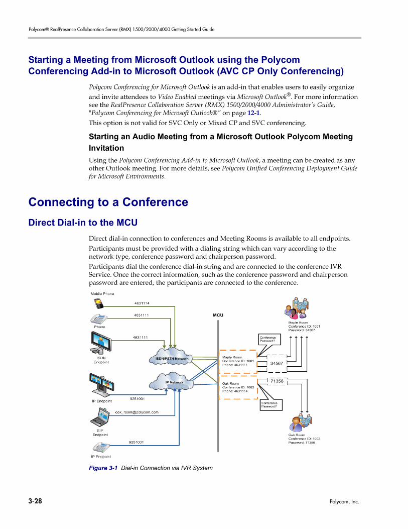
Polycom® RealPresence Collaboration Server (RMX) 1500/2000/4000 Getting Started Guide
Starting a Meeting from Microsoft Outlook using the Polycom Conferencing Add-in to Microsoft Outlook (AVC CP Only Conferencing)
Polycom Conferencing for Microsoft Outlook is an add-in that enables users to easily organize and invite attendees to Video Enabled meetings via Microsoft Outlook®. For more information see the RealPresence Collaboration Server (RMX) 1500/2000/4000 Administrator’s Guide, "Polycom Conferencing for Microsoft Outlook®” on page 12-1.This option is not valid for SVC Only or Mixed CP and SVC conferencing.
Starting an Audio Meeting from a Microsoft Outlook Polycom Meeting
Invitation
Using the Polycom Conferencing Add-in to Microsoft Outlook, a meeting can be created as any other Outlook meeting. For more details, see Polycom Unified Conferencing Deployment Guide for Microsoft Environments.
Connecting to a Conference
Direct Dial-in to the MCU
Direct dial-in connection to conferences and Meeting Rooms is available to all endpoints.Participants must be provided with a dialing string which can vary according to the network type, conference password and chairperson password.Participants dial the conference dial-in string and are connected to the conference IVR Service. Once the correct information, such as the conference password and chairperson password are entered, the participants are connected to the conference.
Figure 3-1 Dial-in Connection via IVR System
3-28 Polycom, Inc.
Chapter 3-Basic Operation
In SVC Only Conferencing Mode, only SIP dial-in using the SVC protocol is available as follows:• AVC-capable endpoints (participants) can only connect to an AVC Meeting Room.
When dialing into SVC Only Meeting Room the calls fail.• SVC-capable endpoints support both AVC and SVC video protocols. When dialing into
SVC Only conferences, they connect as SVC endpoints. When dialing into AVC Only conferences, they connect as AVC endpoints.
In CP AVC or Mixed CP and SVC Conferencing Mode, the MCU can be configured to enable the chairperson to use the chairperson password as the conference password without the need to enter the conference password.
In a Mixed CP and SVC conference, AVC-based dial-in and dial-out participants (H.323 and SIP) and SVC-based dial-in participants only can connect the conference.
H.323 Participants (AVC CP Only and Mixed CP and SVC Conferencing)
For H.323 participants, the dialing string is composed of the MCU prefix in the Gatekeeper and the conference ID.
Example:Prefix in gatekeeper 925Conference ID 1001Conference Name Maple_Room>> The participant dials 9251001 or 925Maple_roomIf there is no gatekeeper defined for the network, H.323 participants dial the MCU’s signaling host IP address and the conference ID, separated by ##.
Example:MCU (Signaling Host) IP address 172.22.30.40
Conference ID 1001
>> The participant dials 172.22.30.40##1001
SIP Participants (AVC CP, Mixed CP and SVC and SVC Conferencing)
For SIP participants the dialing string is composed of:
• The conference routing name and domain name in the following format:conference_routing_name@domain_name
• The conference routing name and the IP address of the MCU signaling in the following format:conference_routing_name@IP Address of the MCU Signaling
Example:Conference routing name 1001
MCU domain name polycom.comMCU (Signaling Host) IP address 172.22.20.42>> The participant dials [email protected]
or:>> The participant dials [email protected]
Polycom, Inc. 3-29
Polycom® RealPresence Collaboration Server (RMX) 1500/2000/4000 Getting Started Guide
ISDN/PSTN Participants (AVC Only Conferencing)
Dial-in ISDN and PSTN participants dial one of the dial-in numbers assigned to the conference/Meeting Room/Reservation/Conference Template, including the country and area code (if needed). They are routed to their conference according to the dial-in number.Example:Assigned dial-in number 4631111
The participant dials 4631111
When adding a defined dial-out participant to the conference, and that participant dials in as an undefined participant before she or he is called by the system, the Collaboration Server is unable to identify that it is the same participant and will have two separate participant entries in the conference for the same participant. In such a case, since the dial-in participant is already connected, the dial-out participant will be displayed as disconnected (line is busy).
For MCUs registered to a gatekeeper, the RMX can be configured to dial and receive calls to and from H.323 endpoints using the IP address in the event that the Gatekeeper is not functioning. Direct IP dialing is enabled or disabled by the GK_MANDATORY_FOR_CALLS_OUT and GK_MANDATORY_FOR_CALLS_IN System Flags. For more information, see the RealPresence Collaboration Server (RMX) 1500/2000/4000 Administrator’s Guide, "Direct IP Dialing” on page 8-16.
3-30 Polycom, Inc.
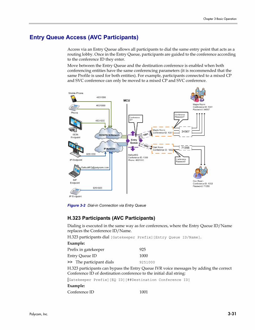
Chapter 3-Basic Operation
Entry Queue Access (AVC Participants)
Access via an Entry Queue allows all participants to dial the same entry point that acts as a routing lobby. Once in the Entry Queue, participants are guided to the conference according to the conference ID they enter.Move between the Entry Queue and the destination conference is enabled when both conferencing entities have the same conferencing parameters (it is recommended that the same Profile is used for both entities). For example, participants connected to a mixed CP and SVC conference can only be moved to a mixed CP and SVC conference.
Figure 3-2 Dial-in Connection via Entry Queue
H.323 Participants (AVC Participants)
Dialing is executed in the same way as for conferences, where the Entry Queue ID/Name replaces the Conference ID/Name.H.323 participants dial [Gatekeeper Prefix][Entry Queue ID/Name].Example:Prefix in gatekeeper 925Entry Queue ID 1000>> The participant dials 9251000H.323 participants can bypass the Entry Queue IVR voice messages by adding the correct Conference ID of destination conference to the initial dial string:[Gatekeeper Prefix][EQ ID][##Destination Conference ID]Example:Conference ID 1001
Polycom, Inc. 3-31
Polycom® RealPresence Collaboration Server (RMX) 1500/2000/4000 Getting Started Guide
>> H.323 participants dial 9251000##1001
H.323 participants can also bypass the conference IVR voice messages by adding the Conference Password to the initial dial string: [Gatekeeper Prefix][EQ ID][##Destination Conference ID][##Password]
Example:Conference ID 1001Conference Password 34567>> H.323 participants dial 9251000##1001##34567
SIP Participants (AVC Participants)
Using an Entry Queue minimizes the number of conferences that require registration with the SIP server and enables using one URI address for all dial-in connections, using the format:<Entry Queue routing name>@<domain name> or
<Entry Queue routing name>@<MCU signaling IP Address>
Example:Entry Queue Routing Name DefaultEQDomain Name polycom.comMCU Signaling IP address 172.22.20.42>> SIP participants dial [email protected], or
ISDN and PSTN Participants
Up to two dial-in numbers can be allocated to an Entry Queue for use by ISDN and PSTN participants.Calls to numbers within the ISDN and PSTN Dial-in Range that are not allocated to an Entry Queue are routed to the Transit Entry Queue.Dial-in ISDN and PSTN participants dial one of the dial-in numbers assigned to the Entry Queue, including the country and area code (if needed). They are routed to their conference according to the conference ID.
Example:Entry Queue ID 1000Assigned Dial-in number 4631000>> ISDN/PSTN participants dial 4631000
3-32 Polycom, Inc.
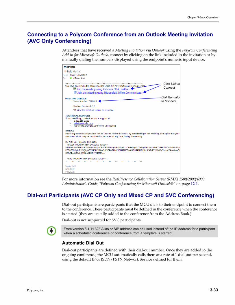
Chapter 3-Basic Operation
Connecting to a Polycom Conference from an Outlook Meeting Invitation (AVC Only Conferencing)
Attendees that have received a Meeting Invitation via Outlook using the Polycom Conferencing Add-in for Microsoft Outlook, connect by clicking on the link included in the invitation or by manually dialing the numbers displayed using the endpoint's numeric input device.
For more information see the RealPresence Collaboration Server (RMX) 1500/2000/4000 Administrator’s Guide, "Polycom Conferencing for Microsoft Outlook®” on page 12-1.
Dial-out Participants (AVC CP Only and Mixed CP and SVC Conferencing)
Dial-out participants are participants that the MCU dials to their endpoint to connect them to the conference. These participants must be defined in the conference when the conference is started (they are usually added to the conference from the Address Book.)
Dial-out is not supported for SVC participants.
Automatic Dial Out
Dial-out participants are defined with their dial-out number. Once they are added to the ongoing conference, the MCU automatically calls them at a rate of 1 dial-out per second, using the default IP or ISDN/PSTN Network Service defined for them.
Click Link toConnect
Dial Manually to Connect
From version 8.1, H.323 Alias or SIP address can be used instead of the IP address for a participant when a scheduled conference or conference from a template is started.
Polycom, Inc. 3-33
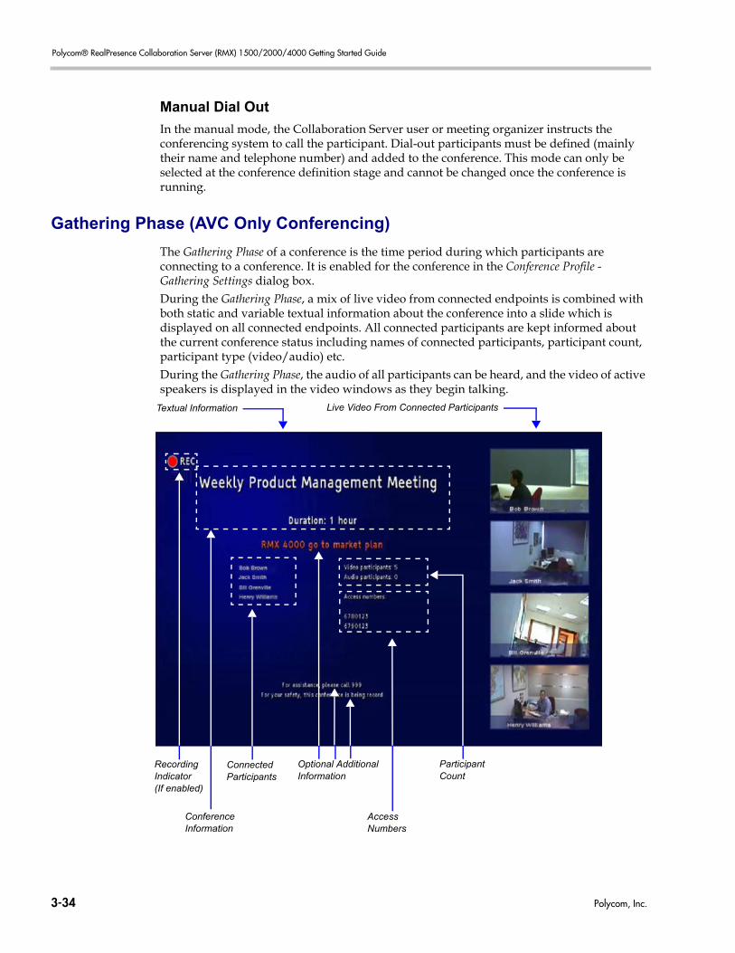
Polycom® RealPresence Collaboration Server (RMX) 1500/2000/4000 Getting Started Guide
Manual Dial Out
In the manual mode, the Collaboration Server user or meeting organizer instructs the conferencing system to call the participant. Dial-out participants must be defined (mainly their name and telephone number) and added to the conference. This mode can only be selected at the conference definition stage and cannot be changed once the conference is running.
Gathering Phase (AVC Only Conferencing)
The Gathering Phase of a conference is the time period during which participants are connecting to a conference. It is enabled for the conference in the Conference Profile - Gathering Settings dialog box.During the Gathering Phase, a mix of live video from connected endpoints is combined with both static and variable textual information about the conference into a slide which is displayed on all connected endpoints. All connected participants are kept informed about the current conference status including names of connected participants, participant count, participant type (video/audio) etc.During the Gathering Phase, the audio of all participants can be heard, and the video of active speakers is displayed in the video windows as they begin talking.
Live Video From Connected ParticipantsTextual Information
Recording Indicator(If enabled)
ConferenceInformation
ConnectedParticipants
AccessNumbers
ParticipantCount
Optional Additional Information
3-34 Polycom, Inc.
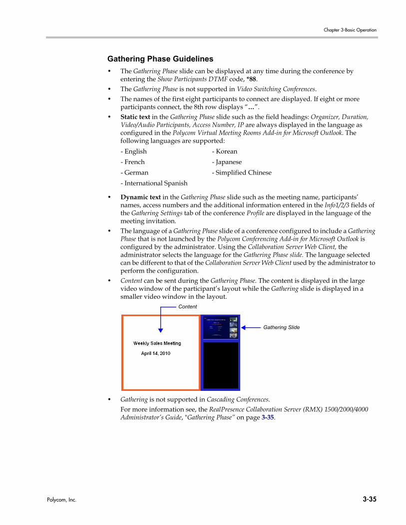
Chapter 3-Basic Operation
Gathering Phase Guidelines
• The Gathering Phase slide can be displayed at any time during the conference by entering the Show Participants DTMF code, *88.
• The Gathering Phase is not supported in Video Switching Conferences.• The names of the first eight participants to connect are displayed. If eight or more
participants connect, the 8th row displays “…”.• Static text in the Gathering Phase slide such as the field headings: Organizer, Duration,
Video/Audio Participants, Access Number, IP are always displayed in the language as configured in the Polycom Virtual Meeting Rooms Add-in for Microsoft Outlook. The following languages are supported:
• Dynamic text in the Gathering Phase slide such as the meeting name, participants’ names, access numbers and the additional information entered in the Info1/2/3 fields of the Gathering Settings tab of the conference Profile are displayed in the language of the meeting invitation.
• The language of a Gathering Phase slide of a conference configured to include a Gathering Phase that is not launched by the Polycom Conferencing Add-in for Microsoft Outlook is configured by the administrator. Using the Collaboration Server Web Client, the administrator selects the language for the Gathering Phase slide. The language selected can be different to that of the Collaboration Server Web Client used by the administrator to perform the configuration.
• Content can be sent during the Gathering Phase. The content is displayed in the large video window of the participant’s layout while the Gathering slide is displayed in a smaller video window in the layout.
• Gathering is not supported in Cascading Conferences.For more information see, the RealPresence Collaboration Server (RMX) 1500/2000/4000 Administrator’s Guide, "Gathering Phase” on page 3-35.
- English - Korean
- French - Japanese
- German - Simplified Chinese
- International Spanish
Gathering Slide
Content
Polycom, Inc. 3-35
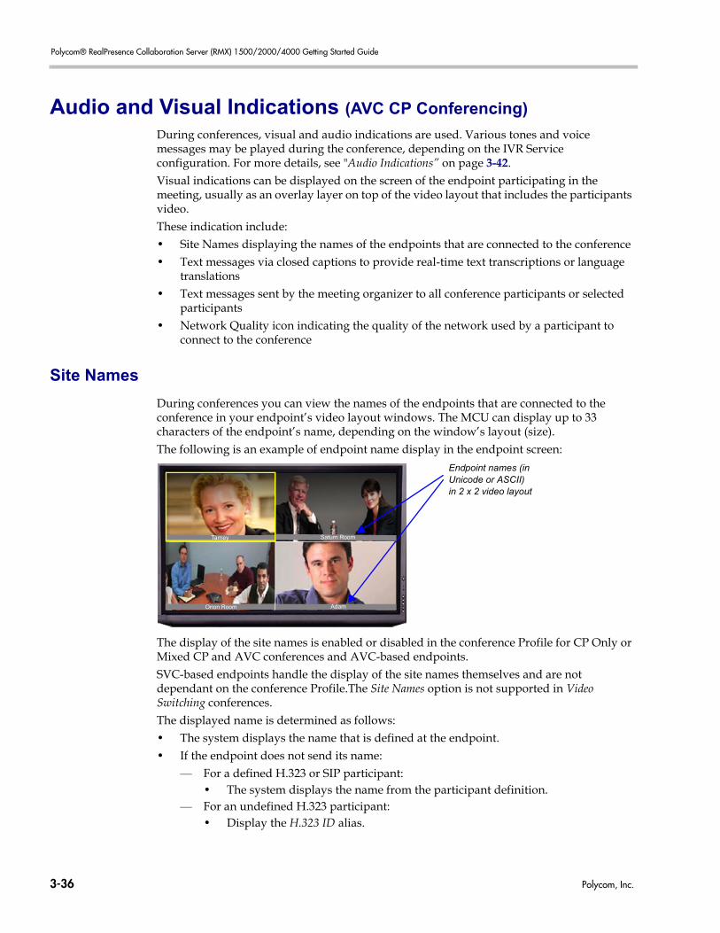
Polycom® RealPresence Collaboration Server (RMX) 1500/2000/4000 Getting Started Guide
Audio and Visual Indications (AVC CP Conferencing)
During conferences, visual and audio indications are used. Various tones and voice messages may be played during the conference, depending on the IVR Service configuration. For more details, see "Audio Indications” on page 3-42.Visual indications can be displayed on the screen of the endpoint participating in the meeting, usually as an overlay layer on top of the video layout that includes the participants video.These indication include: • Site Names displaying the names of the endpoints that are connected to the conference• Text messages via closed captions to provide real-time text transcriptions or language
translations• Text messages sent by the meeting organizer to all conference participants or selected
participants• Network Quality icon indicating the quality of the network used by a participant to
connect to the conference
Site Names
During conferences you can view the names of the endpoints that are connected to the conference in your endpoint’s video layout windows. The MCU can display up to 33 characters of the endpoint’s name, depending on the window’s layout (size). The following is an example of endpoint name display in the endpoint screen:
The display of the site names is enabled or disabled in the conference Profile for CP Only or Mixed CP and AVC conferences and AVC-based endpoints. SVC-based endpoints handle the display of the site names themselves and are not dependant on the conference Profile.The Site Names option is not supported in Video Switching conferences. The displayed name is determined as follows:• The system displays the name that is defined at the endpoint.• If the endpoint does not send its name:
— For a defined H.323 or SIP participant:• The system displays the name from the participant definition.
— For an undefined H.323 participant:• Display the H.323 ID alias.
Endpoint names (in Unicode or ASCII)in 2 x 2 video layout
Orion Room
Saturn RoomTarney
Adam
3-36 Polycom, Inc.
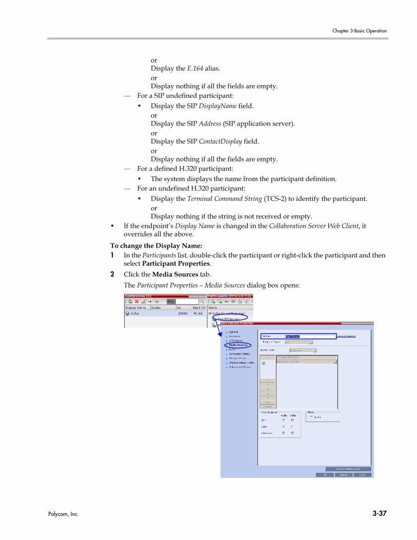
Chapter 3-Basic Operation
orDisplay the E.164 alias. orDisplay nothing if all the fields are empty.
— For a SIP undefined participant:• Display the SIP DisplayName field.
orDisplay the SIP Address (SIP application server).orDisplay the SIP ContactDisplay field.or Display nothing if all the fields are empty.
— For a defined H.320 participant:• The system displays the name from the participant definition.
— For an undefined H.320 participant:• Display the Terminal Command String (TCS-2) to identify the participant.
orDisplay nothing if the string is not received or empty.
• If the endpoint’s Display Name is changed in the Collaboration Server Web Client, it overrides all the above.
To change the Display Name:1 In the Participants list, double-click the participant or right-click the participant and then
select Participant Properties.
2 Click the Media Sources tab.
The Participant Properties – Media Sources dialog box opens:
Polycom, Inc. 3-37
Polycom® RealPresence Collaboration Server (RMX) 1500/2000/4000 Getting Started Guide
3 Enter the new Display Name in the Name field.
4 Click OK.
Displaying and Hiding Site Names
Prior to Version 7.6, Site Names display was enabled or disabled by the HIDE_SITE_NAMES System Flag. In Version 7.6, Site Names display was enabled or disabled using a check box in the Conference Properties - Video Settings dialog box. From version 7.6.1:• In MPM+ Mode - Site Names display is still enabled or disabled using a check box in the
Conference Properties - Video Settings dialog box.• In MPMx Mode - All Site Names display characteristics are controlled using the
Site Names tab in the New Profile and Conference Properties dialog boxes. For more information see RealPresence Collaboration Server (RMX) 1500/2000/4000 Administrator’s Guide, "Defining New Profiles” on page 2-25.
Transparent Site Names
Endpoint name backgrounds are 50% transparent, and while maintaining contrast, do not completely obscure the overlaid video.In previous versions Site Name Transparency was enabled or disabled by adding a new System Flag, SITE_NAME_TRANSPARENCY to the System Configuration and setting its value to NO. For more information, see the RealPresence Collaboration Server (RMX) 1500/2000/4000 Administrator’s Guide Administrator’s Guide, "Manually Adding and Deleting System Flags” on page 21-12.From version 7.6.1:• In MPM+ Mode - Site Name Transparency is still enabled or disabled using the
SITE_NAME_TRANSPARENCY System Flag.
• In MPMx Mode - Site Name Transparency is controlled using the Site Names tab in the New Profile and Conference Properties dialog boxes.
For more information see RealPresence Collaboration Server (RMX) 1500/2000/4000 Administrator’s Guide, "Defining New Profiles” on page 2-25.
Permanent Display of Site Names
Site Names can be permanently displayed on the screens of the endpoints.In previous versions permanent display of Site Names was enabled or disabled by adding a new System Flag, SITE_NAMES_ALWAYS_ON to the System Configuration and setting its value to YES. For more information, see the Polycom® RMX™ 1800, "Manually Adding and Deleting System Flags” on page 21-12.From version 7.6.1:
MPM+ is not supported from version 8.1.
3-38 Polycom, Inc.
Chapter 3-Basic Operation
• In MPM+ Mode - Permanent display of Site Names was still enabled or disabled using the SITE_NAMES_ALWAYS_ON System Flag.
• In MPMx Mode - Permanent display of Site Names is controlled using the Site Names tab in the New Profile and Conference Properties dialog boxes.
For more information see RealPresence Collaboration Server (RMX) 1500/2000/4000 Administrator’s Guide, "Defining New Profiles” on page 2-25.
Location of Site Names
The default location (top left) of the Site Names in the video layout can be changed. In previous versions the location of Site Names display was determined by adding a new System Flag, SITE_NAMES_LOCATION to the System Configuration and setting its value to top, middle, bottom, left or right-justify the Site Names display. For more information, see the RealPresence Collaboration Server (RMX) 1500/2000/4000 Administrator’s Guide, "Manually Adding and Deleting System Flags” on page 21-12.From version 7.6.1:• In MPM+ Mode - The location of Site Names display is still determined by the value of
the SITE_NAMES_LOCATION System Flag.
• In MPMx Mode - All Site Names display characteristics are controlled using the Site Names tab in the New Profile and Conference Properties dialog boxes.
For more information see RealPresence Collaboration Server (RMX) 1500/2000/4000 Administrator’s Guide, "Defining New Profiles” on page 2-25.
Obtaining the Display Name from the Address Book
The MCU can be configured to replace the name of the dial-in IP participant as defined in the endpoint (site name) with the name defined in the address book. In this process, the system retrieves the data (name, alias, number or IP address) of the dial in participant and compares it first with the conference defined dial-in participants and if the endpoint is not found, it then searches for the endpoint with entries in the address book. After a match is found, the system displays the participant name as defined in the address book instead of the site name, in both the video layout and the Collaboration Server Web Client/RMX Manager.The system compares the following endpoint data with the address book entries:• For H.323 participants, the system compares the IP address, Alias, or H.323 number.• For SIP participants, the system compares the IP address or the SIP URI.For more details, see the RealPresence Collaboration Server (RMX) 1500/2000/4000 Administrator’s Guide, "Obtaining the Display Name from the Address Book” on page 8-23.
MPM+ is not supported from version 8.1.
MPM+ is not supported from version 8.1.
Polycom, Inc. 3-39
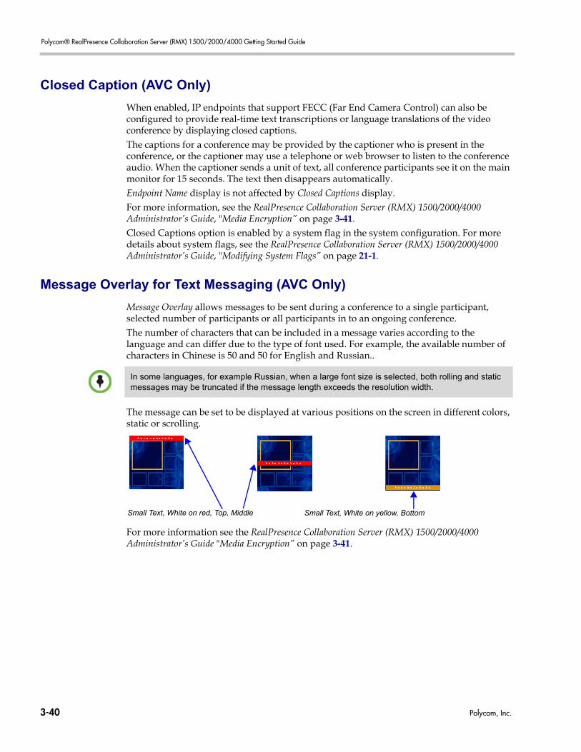
Polycom® RealPresence Collaboration Server (RMX) 1500/2000/4000 Getting Started Guide
Closed Caption (AVC Only)
When enabled, IP endpoints that support FECC (Far End Camera Control) can also be configured to provide real-time text transcriptions or language translations of the video conference by displaying closed captions. The captions for a conference may be provided by the captioner who is present in the conference, or the captioner may use a telephone or web browser to listen to the conference audio. When the captioner sends a unit of text, all conference participants see it on the main monitor for 15 seconds. The text then disappears automatically.Endpoint Name display is not affected by Closed Captions display.For more information, see the RealPresence Collaboration Server (RMX) 1500/2000/4000 Administrator’s Guide, "Media Encryption” on page 3-41.Closed Captions option is enabled by a system flag in the system configuration. For more details about system flags, see the RealPresence Collaboration Server (RMX) 1500/2000/4000 Administrator’s Guide, "Modifying System Flags” on page 21-1.
Message Overlay for Text Messaging (AVC Only)
Message Overlay allows messages to be sent during a conference to a single participant, selected number of participants or all participants in to an ongoing conference.The number of characters that can be included in a message varies according to the language and can differ due to the type of font used. For example, the available number of characters in Chinese is 50 and 50 for English and Russian..
The message can be set to be displayed at various positions on the screen in different colors, static or scrolling.
For more information see the RealPresence Collaboration Server (RMX) 1500/2000/4000 Administrator’s Guide "Media Encryption” on page 3-41.
In some languages, for example Russian, when a large font size is selected, both rolling and static messages may be truncated if the message length exceeds the resolution width.
Small Text, White on red, Top, Middle Small Text, White on yellow, Bottom
3-40 Polycom, Inc.
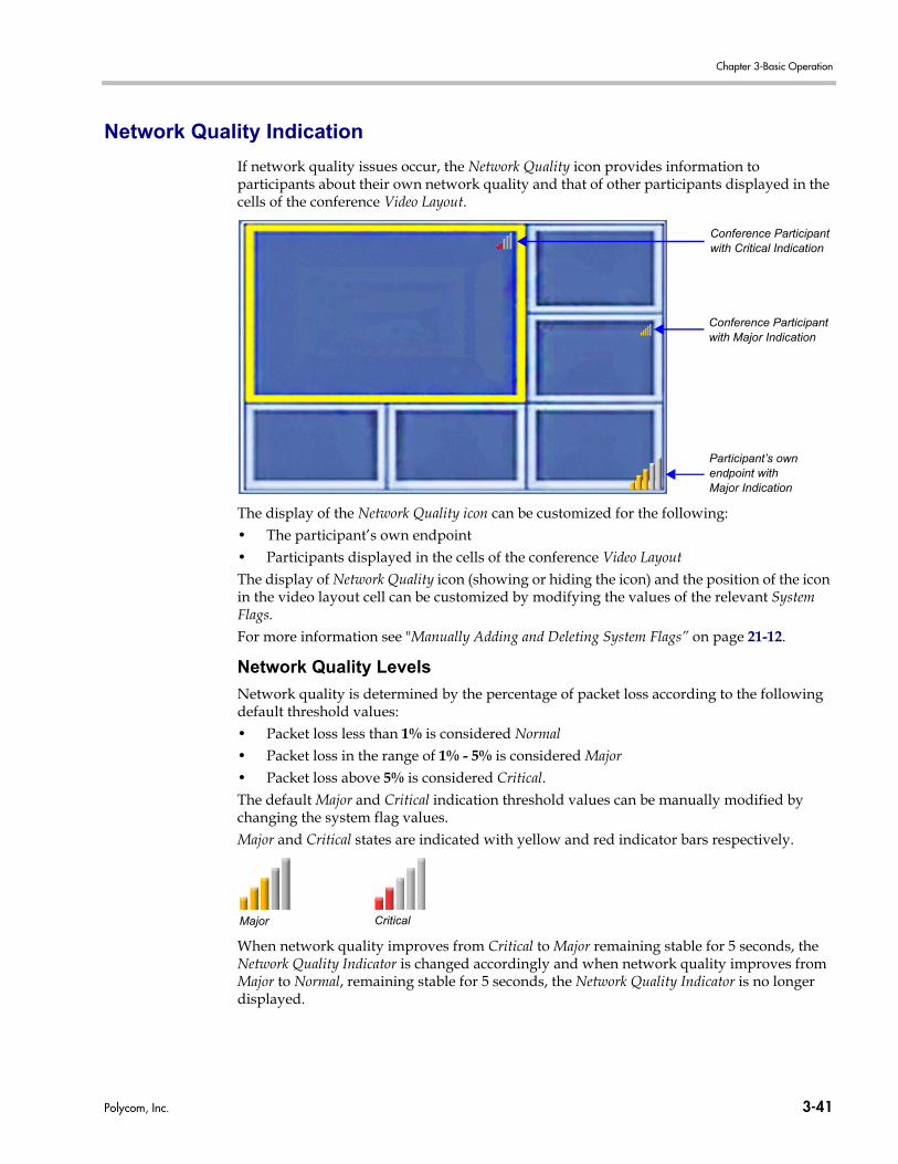
Chapter 3-Basic Operation
Network Quality Indication
If network quality issues occur, the Network Quality icon provides information to participants about their own network quality and that of other participants displayed in the cells of the conference Video Layout.
The display of the Network Quality icon can be customized for the following:• The participant’s own endpoint• Participants displayed in the cells of the conference Video Layout The display of Network Quality icon (showing or hiding the icon) and the position of the icon in the video layout cell can be customized by modifying the values of the relevant System Flags.For more information see "Manually Adding and Deleting System Flags” on page 21-12.
Network Quality Levels
Network quality is determined by the percentage of packet loss according to the following default threshold values:• Packet loss less than 1% is considered Normal • Packet loss in the range of 1% - 5% is considered Major• Packet loss above 5% is considered Critical.The default Major and Critical indication threshold values can be manually modified by changing the system flag values.Major and Critical states are indicated with yellow and red indicator bars respectively.
When network quality improves from Critical to Major remaining stable for 5 seconds, the Network Quality Indicator is changed accordingly and when network quality improves from Major to Normal, remaining stable for 5 seconds, the Network Quality Indicator is no longer displayed.
Conference Participant with Major Indication
Conference Participant with Critical Indication
Participant’s own endpoint with Major Indication
Major Critical
Polycom, Inc. 3-41
Polycom® RealPresence Collaboration Server (RMX) 1500/2000/4000 Getting Started Guide
Guidelines
Network Quality Indicators are displayed for:• The Video Channel only in AVC Conferencing Mode.
Content, Audio and FECC Channel quality issues are not indicated.• The participant’s own endpoint:
— Network Quality Indicators are displayed by default and can be disabled— For media transmitted to and received from the RMX (Video in / Video out).
• Participants displayed in the cells of the conference Video Layout:— Network Quality Indicators are not displayed by default and can be enabled— The media transmitted from the endpoint to the RMX (Video in).
Network Quality Indicators:• Are supported with MPMx cards only• Are not supported in:
— SVC Conferencing Mode— AVC - Video switched conferences
Audio Indications
During the definition of the IVR Service which is assigned to the conference, you can enable any of the audio tones (Entry tone and Exit tone) or voice messages (when a participant joins the conference or leaves the conference) to be heard during an ongoing conference. If Roll Call is enabled for the conference, a roll call can be requested. In addition, various other massages may be heard during the conference, if enabled. For example, when the conference is being recorded, or when the conference is locked.
Noisy Line Detection and Automatic Muting of Noisy Endpoints
The Collaboration Server can detect AVC-enabled endpoints with a noisy audio channel and automatically mute them, reducing the noise heard by other conference participants. When the auto muted endpoint becomes the “speaker” the endpoint is automatically un-muted by the system. If the speaker halts his/her conversation and the line still emits noises, the endpoint will be automatically muted again.When the endpoints are automatically muted by the MCU, no indication is displayed in the Collaboration Server Web Client or RMX Manager as the system does not consider it as a “real” mute.For more information see "Automatic Suppression of Noisy Endpoints” on page 3-87.
3-42 Polycom, Inc.
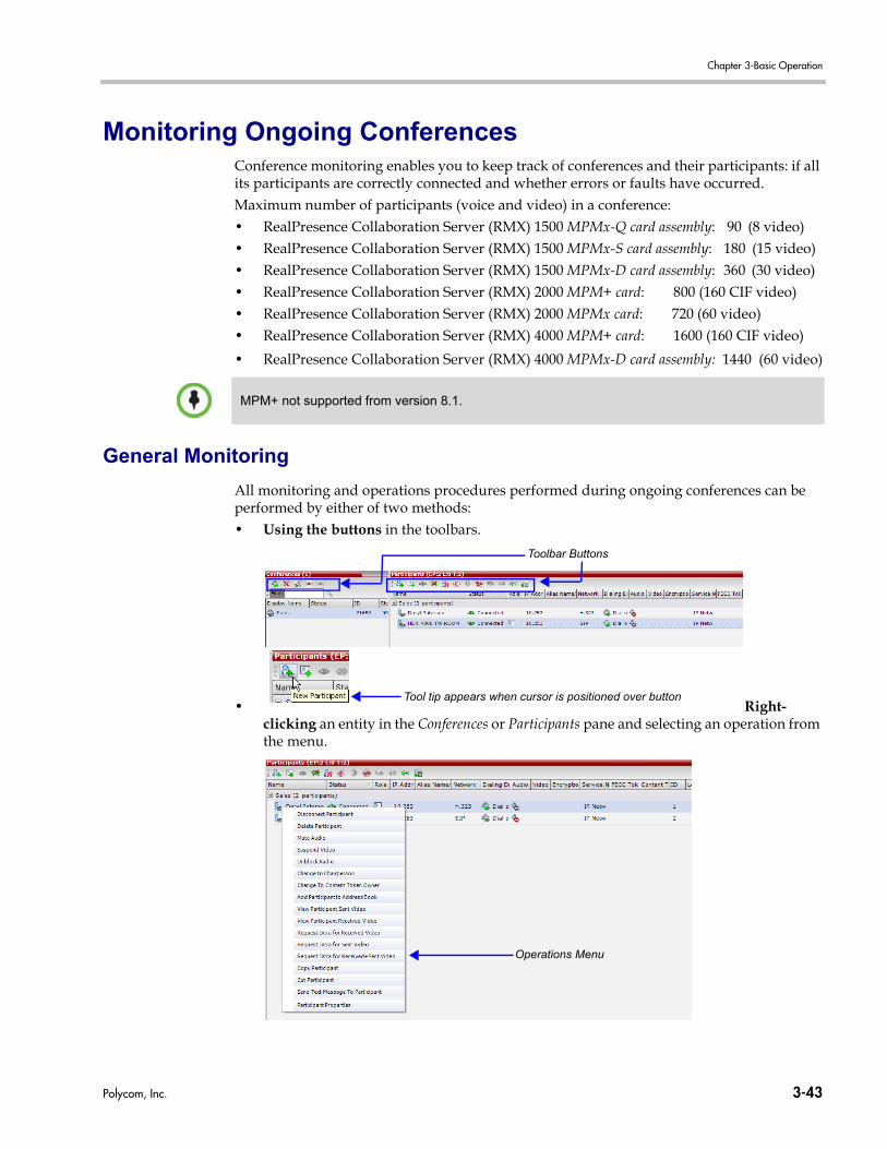
Chapter 3-Basic Operation
Monitoring Ongoing ConferencesConference monitoring enables you to keep track of conferences and their participants: if all its participants are correctly connected and whether errors or faults have occurred.Maximum number of participants (voice and video) in a conference: • RealPresence Collaboration Server (RMX) 1500 MPMx-Q card assembly: 90 (8 video)• RealPresence Collaboration Server (RMX) 1500 MPMx-S card assembly: 180 (15 video)• RealPresence Collaboration Server (RMX) 1500 MPMx-D card assembly: 360 (30 video)• RealPresence Collaboration Server (RMX) 2000 MPM+ card: 800 (160 CIF video)• RealPresence Collaboration Server (RMX) 2000 MPMx card: 720 (60 video)• RealPresence Collaboration Server (RMX) 4000 MPM+ card: 1600 (160 CIF video)
• RealPresence Collaboration Server (RMX) 4000 MPMx-D card assembly: 1440 (60 video)
General Monitoring
All monitoring and operations procedures performed during ongoing conferences can be performed by either of two methods:• Using the buttons in the toolbars.
• Right-clicking an entity in the Conferences or Participants pane and selecting an operation from the menu.
MPM+ not supported from version 8.1.
Toolbar Buttons
Tool tip appears when cursor is positioned over button
Operations Menu
Polycom, Inc. 3-43
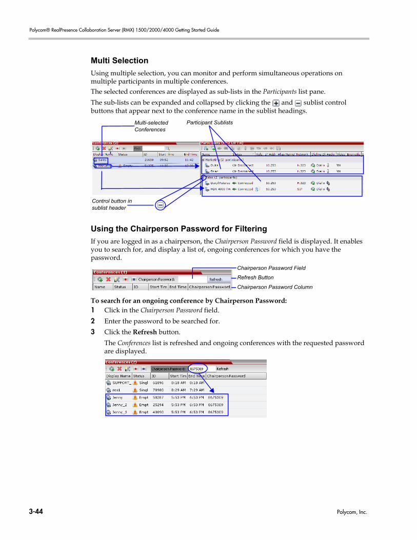
Polycom® RealPresence Collaboration Server (RMX) 1500/2000/4000 Getting Started Guide
Multi Selection
Using multiple selection, you can monitor and perform simultaneous operations on multiple participants in multiple conferences. The selected conferences are displayed as sub-lists in the Participants list pane.
The sub-lists can be expanded and collapsed by clicking the and sublist control buttons that appear next to the conference name in the sublist headings.
Using the Chairperson Password for Filtering
If you are logged in as a chairperson, the Chairperson Password field is displayed. It enables you to search for, and display a list of, ongoing conferences for which you have the password.
To search for an ongoing conference by Chairperson Password: 1 Click in the Chairperson Password field.
2 Enter the password to be searched for.
3 Click the Refresh button.
The Conferences list is refreshed and ongoing conferences with the requested password are displayed.
Control button insublist header
Multi-selectedConferences
Participant Sublists
Chairperson Password Field
Chairperson Password Column
Refresh Button
3-44 Polycom, Inc.
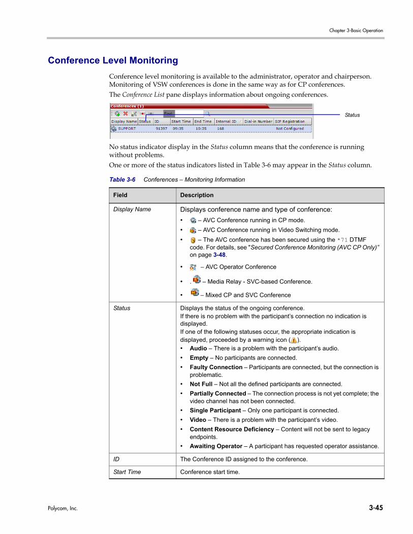
Chapter 3-Basic Operation
Conference Level Monitoring
Conference level monitoring is available to the administrator, operator and chairperson. Monitoring of VSW conferences is done in the same way as for CP conferences. The Conference List pane displays information about ongoing conferences.
No status indicator display in the Status column means that the conference is running without problems.One or more of the status indicators listed in Table 3-6 may appear in the Status column.
Table 3-6 Conferences – Monitoring Information
Field Description
Display Name Displays conference name and type of conference:
• – AVC Conference running in CP mode.
• – AVC Conference running in Video Switching mode.
• – The AVC conference has been secured using the *71 DTMF code. For details, see "Secured Conference Monitoring (AVC CP Only)” on page 3-48.
• – AVC Operator Conference
• . – Media Relay - SVC-based Conference.
• – Mixed CP and SVC Conference
Status Displays the status of the ongoing conference.If there is no problem with the participant’s connection no indication is displayed.If one of the following statuses occur, the appropriate indication is displayed, proceeded by a warning icon ( ).
• Audio – There is a problem with the participant’s audio.
• Empty – No participants are connected.
• Faulty Connection – Participants are connected, but the connection is problematic.
• Not Full – Not all the defined participants are connected.
• Partially Connected – The connection process is not yet complete; the video channel has not been connected.
• Single Participant – Only one participant is connected.
• Video – There is a problem with the participant’s video.
• Content Resource Deficiency – Content will not be sent to legacy endpoints.
• Awaiting Operator – A participant has requested operator assistance.
ID The Conference ID assigned to the conference.
Start Time Conference start time.
Status
Polycom, Inc. 3-45
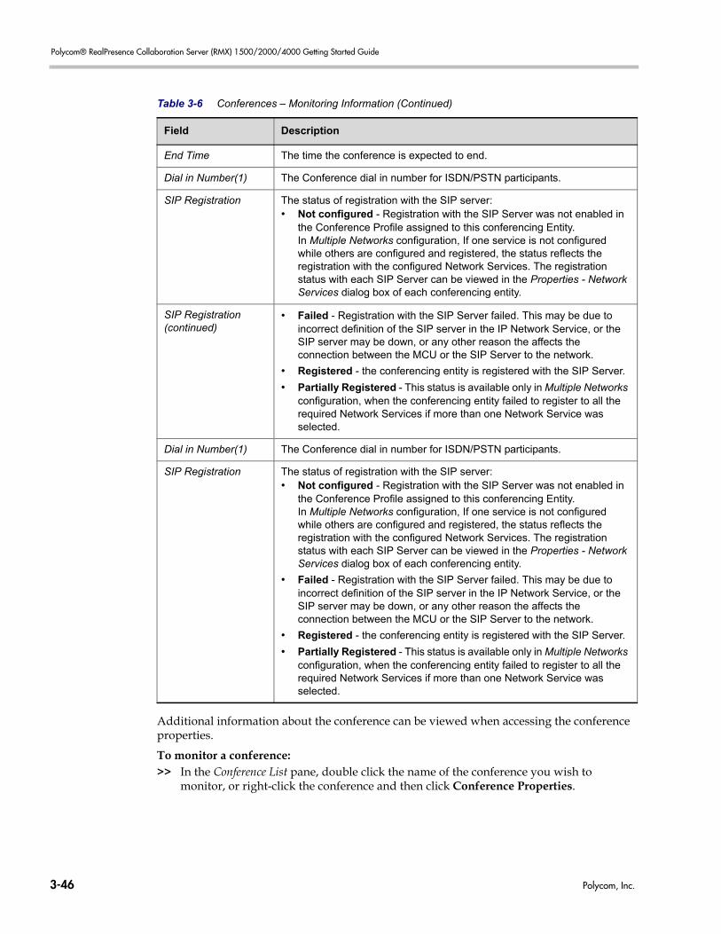
Polycom® RealPresence Collaboration Server (RMX) 1500/2000/4000 Getting Started Guide
Additional information about the conference can be viewed when accessing the conference properties.
To monitor a conference:>> In the Conference List pane, double click the name of the conference you wish to
monitor, or right-click the conference and then click Conference Properties.
End Time The time the conference is expected to end.
Dial in Number(1) The Conference dial in number for ISDN/PSTN participants.
SIP Registration The status of registration with the SIP server:• Not configured - Registration with the SIP Server was not enabled in
the Conference Profile assigned to this conferencing Entity. In Multiple Networks configuration, If one service is not configured while others are configured and registered, the status reflects the registration with the configured Network Services. The registration status with each SIP Server can be viewed in the Properties - Network Services dialog box of each conferencing entity.
SIP Registration (continued)
• Failed - Registration with the SIP Server failed. This may be due to incorrect definition of the SIP server in the IP Network Service, or the SIP server may be down, or any other reason the affects the connection between the MCU or the SIP Server to the network.
• Registered - the conferencing entity is registered with the SIP Server.
• Partially Registered - This status is available only in Multiple Networks configuration, when the conferencing entity failed to register to all the required Network Services if more than one Network Service was selected.
Dial in Number(1) The Conference dial in number for ISDN/PSTN participants.
SIP Registration The status of registration with the SIP server:• Not configured - Registration with the SIP Server was not enabled in
the Conference Profile assigned to this conferencing Entity. In Multiple Networks configuration, If one service is not configured while others are configured and registered, the status reflects the registration with the configured Network Services. The registration status with each SIP Server can be viewed in the Properties - Network Services dialog box of each conferencing entity.
• Failed - Registration with the SIP Server failed. This may be due to incorrect definition of the SIP server in the IP Network Service, or the SIP server may be down, or any other reason the affects the connection between the MCU or the SIP Server to the network.
• Registered - the conferencing entity is registered with the SIP Server.
• Partially Registered - This status is available only in Multiple Networks configuration, when the conferencing entity failed to register to all the required Network Services if more than one Network Service was selected.
Table 3-6 Conferences – Monitoring Information (Continued)
Field Description
3-46 Polycom, Inc.
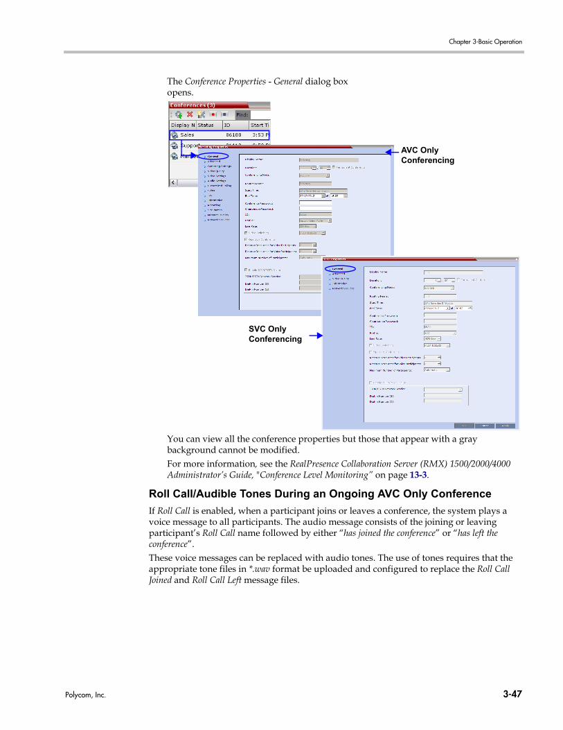
Chapter 3-Basic Operation
The Conference Properties - General dialog box opens.
You can view all the conference properties but those that appear with a gray background cannot be modified.For more information, see the RealPresence Collaboration Server (RMX) 1500/2000/4000 Administrator’s Guide, "Conference Level Monitoring” on page 13-3.
Roll Call/Audible Tones During an Ongoing AVC Only Conference
If Roll Call is enabled, when a participant joins or leaves a conference, the system plays a voice message to all participants. The audio message consists of the joining or leaving participant’s Roll Call name followed by either “has joined the conference” or “has left the conference”.These voice messages can be replaced with audio tones. The use of tones requires that the appropriate tone files in *.wav format be uploaded and configured to replace the Roll Call Joined and Roll Call Left message files.
AVC Only Conferencing
SVC Only Conferencing
Polycom, Inc. 3-47
Polycom® RealPresence Collaboration Server (RMX) 1500/2000/4000 Getting Started Guide
These options are enabled or disabled by selection in the Conference IVR Service Properties - Roll Call/Notifications dialog box.
For more information see the RealPresence Collaboration Server (RMX) 1500/2000/4000 Administrator’s Guide, "Defining a New Conference IVR Service” on page 17-6.
Audio Only Message (AVC CP Only)
H.323 and SIP video participants that are connected as Secondary (Audio Only) because of a lack of video resources receive an audio message: “All video resources are currently in use. Connecting using audio only” indicating why their video has not connected. For more information see the RealPresence Collaboration Server (RMX) 1500/2000/4000 Administrator’s Guide.
Secured Conference Monitoring (AVC CP Only)
When Secured Conference Mode is enabled on the Collaboration Server, it locks the conference and prevents participants and Collaboration Server Users from joining the conference. A Secured conference cannot be monitored or controlled in any way. While a conference is in the Secure Mode, the Collaboration Server User with Administrator authorization cannot view the participants list or any other conference properties, but can manually terminate it.The conference chairperson can enable or disable the Secure mode from the DTMF input device (touch-tone telephone or the endpoint’s remote control), using the appropriate DTMF code (the default code is *71). During the secure conference, the chairperson and participants can perform various operations, such as muting, via their DTMF input device using the appropriate DTMF codes. However, because Secure conferences cannot be monitored, these operations or status changes are not displayed in the Conferences or Participants panes.
A special icon is used to indicate that the conference is in Secure mode.
Monitoring Ongoing Gateway Sessions (AVC Only)
Ongoing Gateway Sessions that are created when calling the Gateway Profile, are listed in the ongoing Conferences list pane and are monitored in the same way as the conferences. For more details, see the RealPresence Collaboration Server (RMX) 1500/2000/4000 Administrator’s Guide, "Conference Level Monitoring” on page 13-3.
3-48 Polycom, Inc.
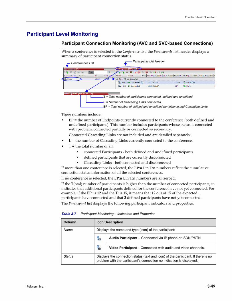
Chapter 3-Basic Operation
Participant Level Monitoring
Participant Connection Monitoring (AVC and SVC-based Connections)
When a conference is selected in the Conference list, the Participants list header displays a summary of participant connection status.
These numbers include:• EP = the number of Endpoints currently connected to the conference (both defined and
undefined participants). This number includes participants whose status is connected with problem, connected partially or connected as secondary.Connected Cascading Links are not included and are detailed separately.
• L = the number of Cascading Links currently connected to the conference.• T = the total number of all:
• connected Participants - both defined and undefined participants• defined participants that are currently disconnected • Cascading Links - both connected and disconnected
If more than one conference is selected, the EP:n L:n T:n numbers reflect the cumulative connection status information of all the selected conferences.If no conference is selected, the EP:n L:n T:n numbers are all zeroed.If the T(otal) number of participants is higher than the number of connected participants, it indicates that additional participants defined for the conference have not yet connected. For example, if the EP: is 12 and the T: is 15, it means that 12 out of 15 of the expected participants have connected and that 3 defined participants have not yet connected.The Participant list displays the following participant indicators and properties:
Table 3-7 Participant Monitoring – Indicators and Properties
Column Icon/Description
Name Displays the name and type (icon) of the participant:
Audio Participant – Connected via IP phone or ISDN/PSTN.
Video Participant – Connected with audio and video channels.
Status Displays the connection status (text and icon) of the participant. If there is no problem with the participant’s connection no indication is displayed.
Conferences ListParticipants List Header
T = Total number of participants connected, defined and undefined
L = Number of Cascading Links connected
EP = Total number of defined and undefined participants and Cascading Links
Polycom, Inc. 3-49
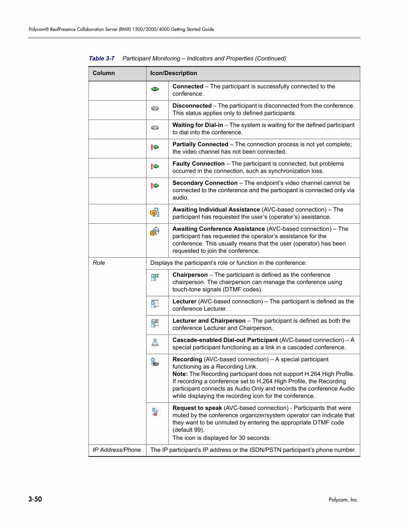
Polycom® RealPresence Collaboration Server (RMX) 1500/2000/4000 Getting Started Guide
Connected – The participant is successfully connected to the conference.
Disconnected – The participant is disconnected from the conference. This status applies only to defined participants.
Waiting for Dial-in – The system is waiting for the defined participant to dial into the conference.
Partially Connected – The connection process is not yet complete; the video channel has not been connected.
Faulty Connection – The participant is connected, but problems occurred in the connection, such as synchronization loss.
Secondary Connection – The endpoint’s video channel cannot be connected to the conference and the participant is connected only via audio.
Awaiting Individual Assistance (AVC-based connection) – The participant has requested the user’s (operator’s) assistance.
Awaiting Conference Assistance (AVC-based connection) – The participant has requested the operator’s assistance for the conference. This usually means that the user (operator) has been requested to join the conference.
Role Displays the participant’s role or function in the conference:
Chairperson – The participant is defined as the conference chairperson. The chairperson can manage the conference using touch-tone signals (DTMF codes).
Lecturer (AVC-based connection) – The participant is defined as the conference Lecturer.
Lecturer and Chairperson – The participant is defined as both the conference Lecturer and Chairperson.
Cascade-enabled Dial-out Participant (AVC-based connection) – A special participant functioning as a link in a cascaded conference.
Recording (AVC-based connection) – A special participant functioning as a Recording Link. Note: The Recording participant does not support H.264 High Profile. If recording a conference set to H,264 High Profile, the Recording participant connects as Audio Only and records the conference Audio while displaying the recording icon for the conference.
Request to speak (AVC-based connection) - Participants that were muted by the conference organizer/system operator can indicate that they want to be unmuted by entering the appropriate DTMF code (default 99).The icon is displayed for 30 seconds.
IP Address/Phone The IP participant’s IP address or the ISDN/PSTN participant’s phone number.
Table 3-7 Participant Monitoring – Indicators and Properties (Continued)
Column Icon/Description
3-50 Polycom, Inc.
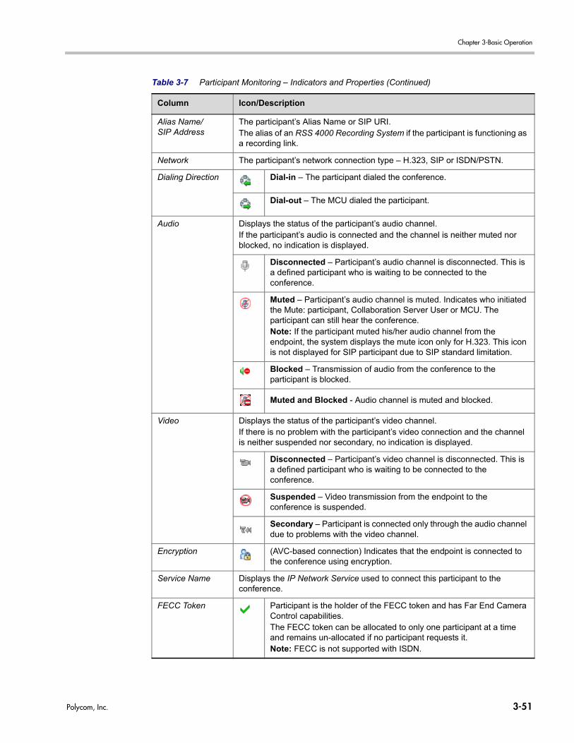
Chapter 3-Basic Operation
Alias Name/SIP Address
The participant’s Alias Name or SIP URI.The alias of an RSS 4000 Recording System if the participant is functioning as a recording link.
Network The participant’s network connection type – H.323, SIP or ISDN/PSTN.
Dialing Direction Dial-in – The participant dialed the conference.
Dial-out – The MCU dialed the participant.
Audio Displays the status of the participant’s audio channel.If the participant’s audio is connected and the channel is neither muted nor blocked, no indication is displayed.
Disconnected – Participant’s audio channel is disconnected. This is a defined participant who is waiting to be connected to the conference.
Muted – Participant’s audio channel is muted. Indicates who initiated the Mute: participant, Collaboration Server User or MCU. The participant can still hear the conference.Note: If the participant muted his/her audio channel from the endpoint, the system displays the mute icon only for H.323. This icon is not displayed for SIP participant due to SIP standard limitation.
Blocked – Transmission of audio from the conference to the participant is blocked.
Muted and Blocked - Audio channel is muted and blocked.
Video Displays the status of the participant’s video channel.If there is no problem with the participant’s video connection and the channel is neither suspended nor secondary, no indication is displayed.
Disconnected – Participant’s video channel is disconnected. This is a defined participant who is waiting to be connected to the conference.
Suspended – Video transmission from the endpoint to the conference is suspended.
Secondary – Participant is connected only through the audio channel due to problems with the video channel.
Encryption (AVC-based connection) Indicates that the endpoint is connected to the conference using encryption.
Service Name Displays the IP Network Service used to connect this participant to the conference.
FECC Token Participant is the holder of the FECC token and has Far End Camera Control capabilities.The FECC token can be allocated to only one participant at a time and remains un-allocated if no participant requests it. Note: FECC is not supported with ISDN.
Table 3-7 Participant Monitoring – Indicators and Properties (Continued)
Column Icon/Description
Polycom, Inc. 3-51
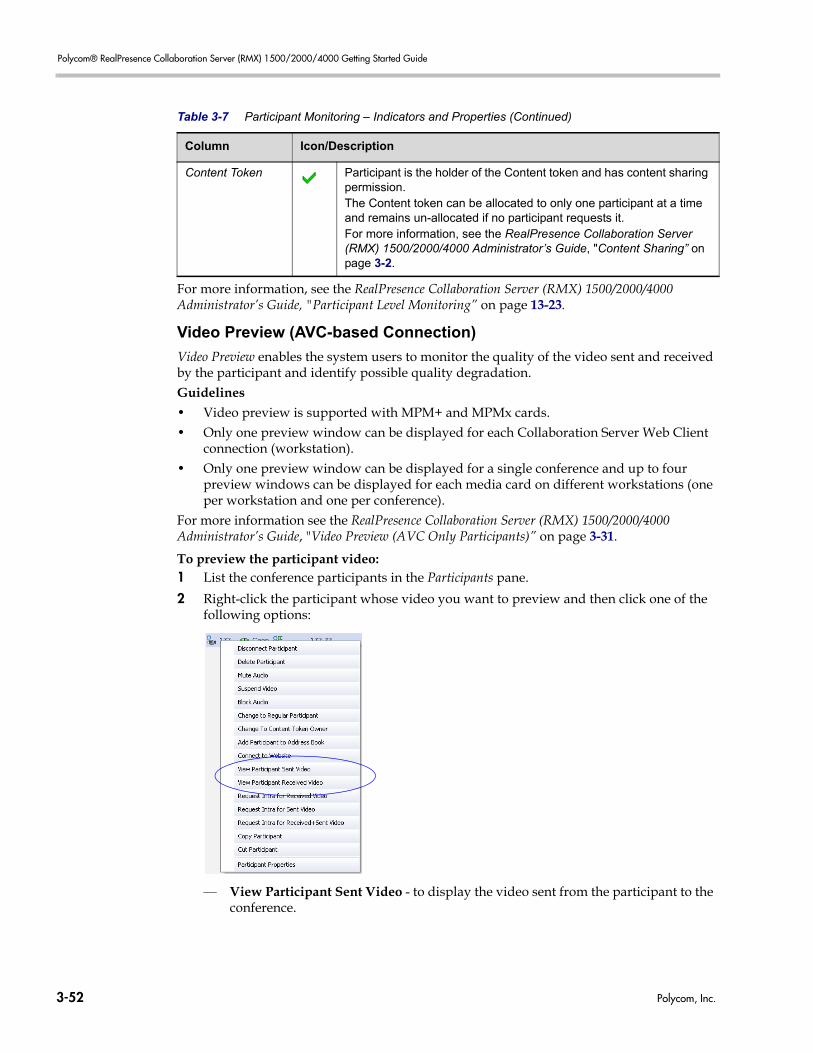
Polycom® RealPresence Collaboration Server (RMX) 1500/2000/4000 Getting Started Guide
For more information, see the RealPresence Collaboration Server (RMX) 1500/2000/4000 Administrator’s Guide, "Participant Level Monitoring” on page 13-23.
Video Preview (AVC-based Connection)
Video Preview enables the system users to monitor the quality of the video sent and received by the participant and identify possible quality degradation.Guidelines• Video preview is supported with MPM+ and MPMx cards.• Only one preview window can be displayed for each Collaboration Server Web Client
connection (workstation).• Only one preview window can be displayed for a single conference and up to four
preview windows can be displayed for each media card on different workstations (one per workstation and one per conference).
For more information see the RealPresence Collaboration Server (RMX) 1500/2000/4000 Administrator’s Guide, "Video Preview (AVC Only Participants)” on page 3-31.
To preview the participant video:1 List the conference participants in the Participants pane.
2 Right-click the participant whose video you want to preview and then click one of the following options:
— View Participant Sent Video - to display the video sent from the participant to the conference.
Content Token Participant is the holder of the Content token and has content sharing permission.The Content token can be allocated to only one participant at a time and remains un-allocated if no participant requests it. For more information, see the RealPresence Collaboration Server (RMX) 1500/2000/4000 Administrator’s Guide, "Content Sharing” on page 3-2.
Table 3-7 Participant Monitoring – Indicators and Properties (Continued)
Column Icon/Description
3-52 Polycom, Inc.
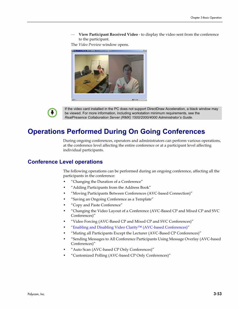
Chapter 3-Basic Operation
— View Participant Received Video - to display the video sent from the conference to the participant.
The Video Preview window opens.
Operations Performed During On Going ConferencesDuring ongoing conferences, operators and administrators can perform various operations, at the conference level affecting the entire conference or at a participant level affecting individual participants.
Conference Level operations
The following operations can be performed during an ongoing conference, affecting all the participants in the conference:• “Changing the Duration of a Conference”• “Adding Participants from the Address Book”• “Moving Participants Between Conferences (AVC-based Connection)”• “Saving an Ongoing Conference as a Template”• “Copy and Paste Conference”• “Changing the Video Layout of a Conference (AVC-Based CP and Mixed CP and SVC
Conferences)”• “Video Forcing (AVC-Based CP and Mixed CP and SVC Conferences)”• “Enabling and Disabling Video Clarity™ (AVC-based Conferences)”• “Muting all Participants Except the Lecturer (AVC-Based CP Conferences)”• “Sending Messages to All Conference Participants Using Message Overlay (AVC-based
Conferences)”• “Auto Scan (AVC-based CP Only Conferences)”• “Customized Polling (AVC-based CP Only Conferences)”
If the video card installed in the PC does not support DirectDraw Acceleration, a black window may be viewed. For more information, including workstation minimum requirements, see the RealPresence Collaboration Server (RMX) 1500/2000/4000 Administrator’s Guide.
Polycom, Inc. 3-53
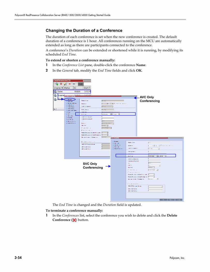
Polycom® RealPresence Collaboration Server (RMX) 1500/2000/4000 Getting Started Guide
Changing the Duration of a Conference
The duration of each conference is set when the new conference is created. The default duration of a conference is 1 hour. All conferences running on the MCU are automatically extended as long as there are participants connected to the conference.A conference’s Duration can be extended or shortened while it is running, by modifying its scheduled End Time.
To extend or shorten a conference manually:1 In the Conference List pane, double-click the conference Name.
2 In the General tab, modify the End Time fields and click OK.
The End Time is changed and the Duration field is updated.
To terminate a conference manually:1 In the Conferences list, select the conference you wish to delete and click the Delete
Conference ( ) button.
AVC Only Conferencing
SVC Only Conferencing
3-54 Polycom, Inc.
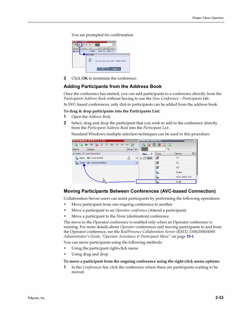
Chapter 3-Basic Operation
You are prompted for confirmation.
2 Click OK to terminate the conference.
Adding Participants from the Address Book
Once the conference has started, you can add participants to a conference directly from the Participants Address Book without having to use the New Conference – Participants tab.In SVC-based conferences, only dial-in participants can be added from the address book.
To drag & drop participants into the Participants List:1 Open the Address Book.
2 Select, drag and drop the participant that you wish to add to the conference directly from the Participant Address Book into the Participant List.
Standard Windows multiple selection techniques can be used in this procedure.
Moving Participants Between Conferences (AVC-based Connection)
Collaboration Server users can assist participants by performing the following operations:• Move participant from one ongoing conference to another• Move a participant to an Operator conference (Attend a participant).• Move a participant to the Home (destination) conference.The move to the Operator conference is enabled only when an Operator conference is running. For more details about Operator conferences and moving participants to and from the Operator conference, see the RealPresence Collaboration Server (RMX) 1500/2000/4000 Administrator’s Guide, "Operator Assistance & Participant Move” on page 10-1.You can move participants using the following methods:• Using the participant right-click menu• Using drag and drop
To move a participant from the ongoing conference using the right-click menu options:1 In the Conferences list, click the conference where there are participants waiting to be
moved.
Polycom, Inc. 3-55
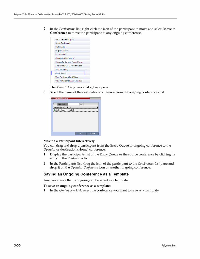
Polycom® RealPresence Collaboration Server (RMX) 1500/2000/4000 Getting Started Guide
2 In the Participants list, right-click the icon of the participant to move and select Move to Conference to move the participant to any ongoing conference.
The Move to Conference dialog box opens.3 Select the name of the destination conference from the ongoing conferences list.
Moving a Participant InteractivelyYou can drag and drop a participant from the Entry Queue or ongoing conference to the Operator or destination (Home) conference:1 Display the participants list of the Entry Queue or the source conference by clicking its
entry in the Conferences list.
2 In the Participants list, drag the icon of the participant to the Conferences List pane and drop it on the Operator Conference icon or another ongoing conference.
Saving an Ongoing Conference as a Template
Any conference that is ongoing can be saved as a template.
To save an ongoing conference as a template:1 In the Conferences List, select the conference you want to save as a Template.
3-56 Polycom, Inc.
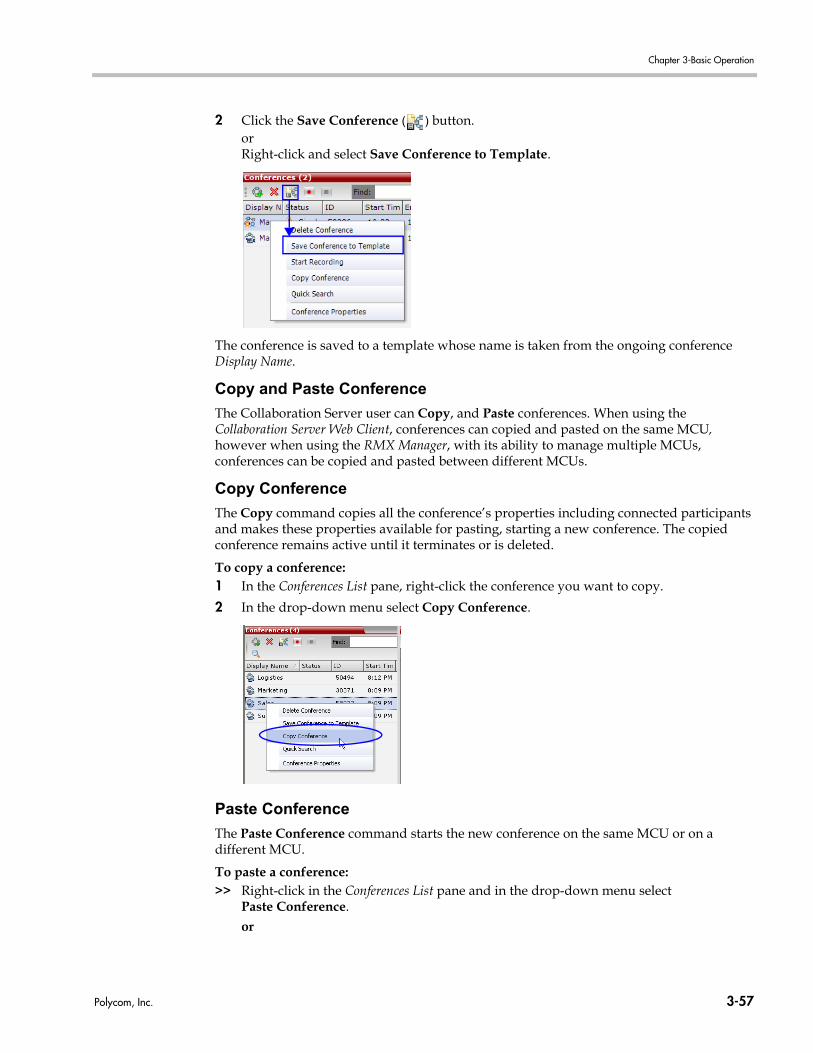
Chapter 3-Basic Operation
2 Click the Save Conference ( ) button.orRight-click and select Save Conference to Template.
The conference is saved to a template whose name is taken from the ongoing conference Display Name.
Copy and Paste Conference
The Collaboration Server user can Copy, and Paste conferences. When using the Collaboration Server Web Client, conferences can copied and pasted on the same MCU, however when using the RMX Manager, with its ability to manage multiple MCUs, conferences can be copied and pasted between different MCUs.
Copy Conference
The Copy command copies all the conference’s properties including connected participants and makes these properties available for pasting, starting a new conference. The copied conference remains active until it terminates or is deleted.
To copy a conference:1 In the Conferences List pane, right-click the conference you want to copy.
2 In the drop-down menu select Copy Conference.
Paste Conference
The Paste Conference command starts the new conference on the same MCU or on a different MCU.
To paste a conference:>> Right-click in the Conferences List pane and in the drop-down menu select
Paste Conference.or
Polycom, Inc. 3-57
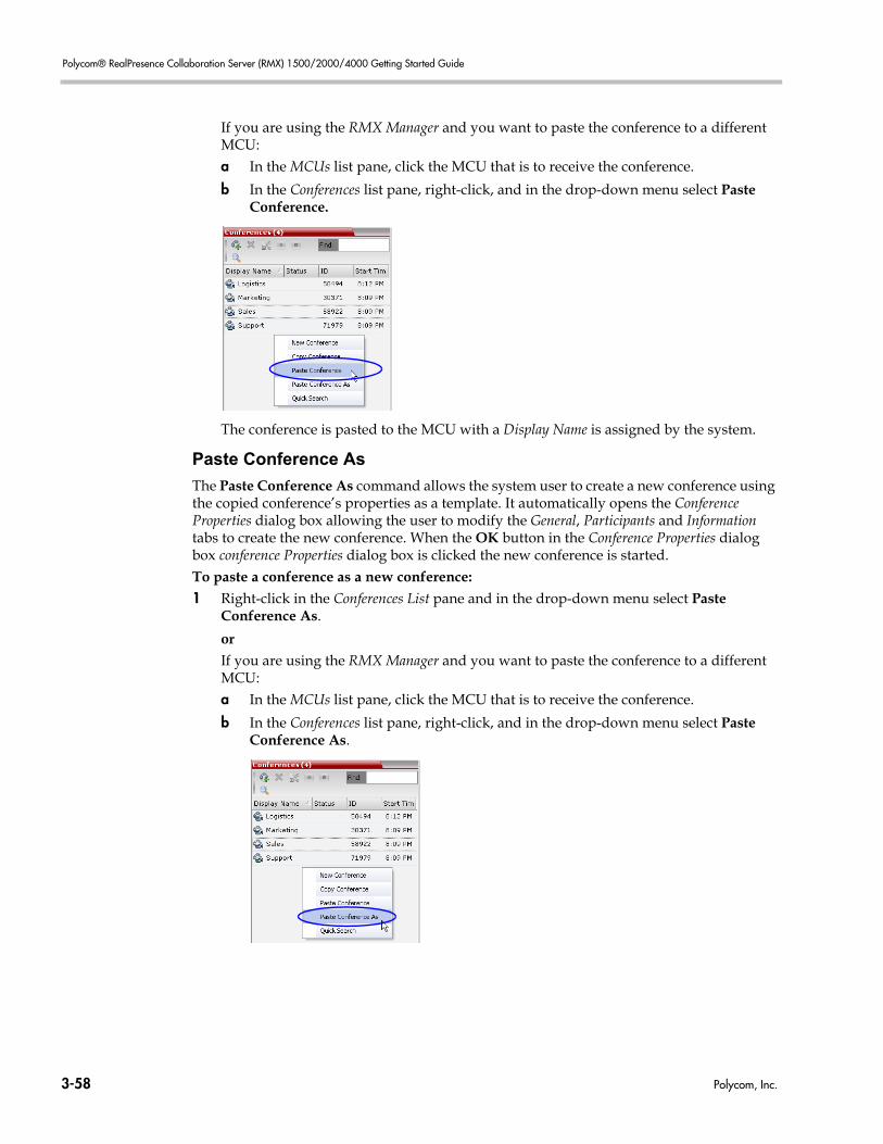
Polycom® RealPresence Collaboration Server (RMX) 1500/2000/4000 Getting Started Guide
If you are using the RMX Manager and you want to paste the conference to a different MCU:a In the MCUs list pane, click the MCU that is to receive the conference.
b In the Conferences list pane, right-click, and in the drop-down menu select Paste Conference.
The conference is pasted to the MCU with a Display Name is assigned by the system.
Paste Conference As
The Paste Conference As command allows the system user to create a new conference using the copied conference’s properties as a template. It automatically opens the Conference Properties dialog box allowing the user to modify the General, Participants and Information tabs to create the new conference. When the OK button in the Conference Properties dialog box conference Properties dialog box is clicked the new conference is started.To paste a conference as a new conference:1 Right-click in the Conferences List pane and in the drop-down menu select Paste
Conference As.
orIf you are using the RMX Manager and you want to paste the conference to a different MCU:a In the MCUs list pane, click the MCU that is to receive the conference.
b In the Conferences list pane, right-click, and in the drop-down menu select Paste Conference As.
3-58 Polycom, Inc.
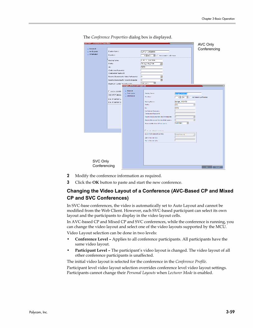
Chapter 3-Basic Operation
The Conference Properties dialog box is displayed.
2 Modify the conference information as required.
3 Click the OK button to paste and start the new conference.
Changing the Video Layout of a Conference (AVC-Based CP and Mixed
CP and SVC Conferences)
In SVC-base conferences, the video is automatically set to Auto Layout and cannot be modified from the Web Client. However, each SVC-based participant can select its own layout and the participants to display in the video layout cells.In AVC-based CP and Mixed CP and SVC conferences, while the conference is running, you can change the video layout and select one of the video layouts supported by the MCU.Video Layout selection can be done in two levels: • Conference Level – Applies to all conference participants. All participants have the
same video layout.• Participant Level – The participant’s video layout is changed. The video layout of all
other conference participants is unaffected.The initial video layout is selected for the conference in the Conference Profile.Participant level video layout selection overrides conference level video layout settings. Participants cannot change their Personal Layouts when Lecturer Mode is enabled.
AVC Only Conferencing
SVC Only Conferencing
Polycom, Inc. 3-59
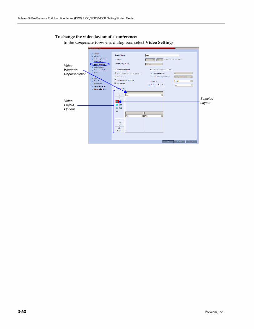
Polycom® RealPresence Collaboration Server (RMX) 1500/2000/4000 Getting Started Guide
To change the video layout of a conference:In the Conference Properties dialog box, select Video Settings.
Video Windows Representation
SelectedLayout
VideoLayoutOptions
3-60 Polycom, Inc.
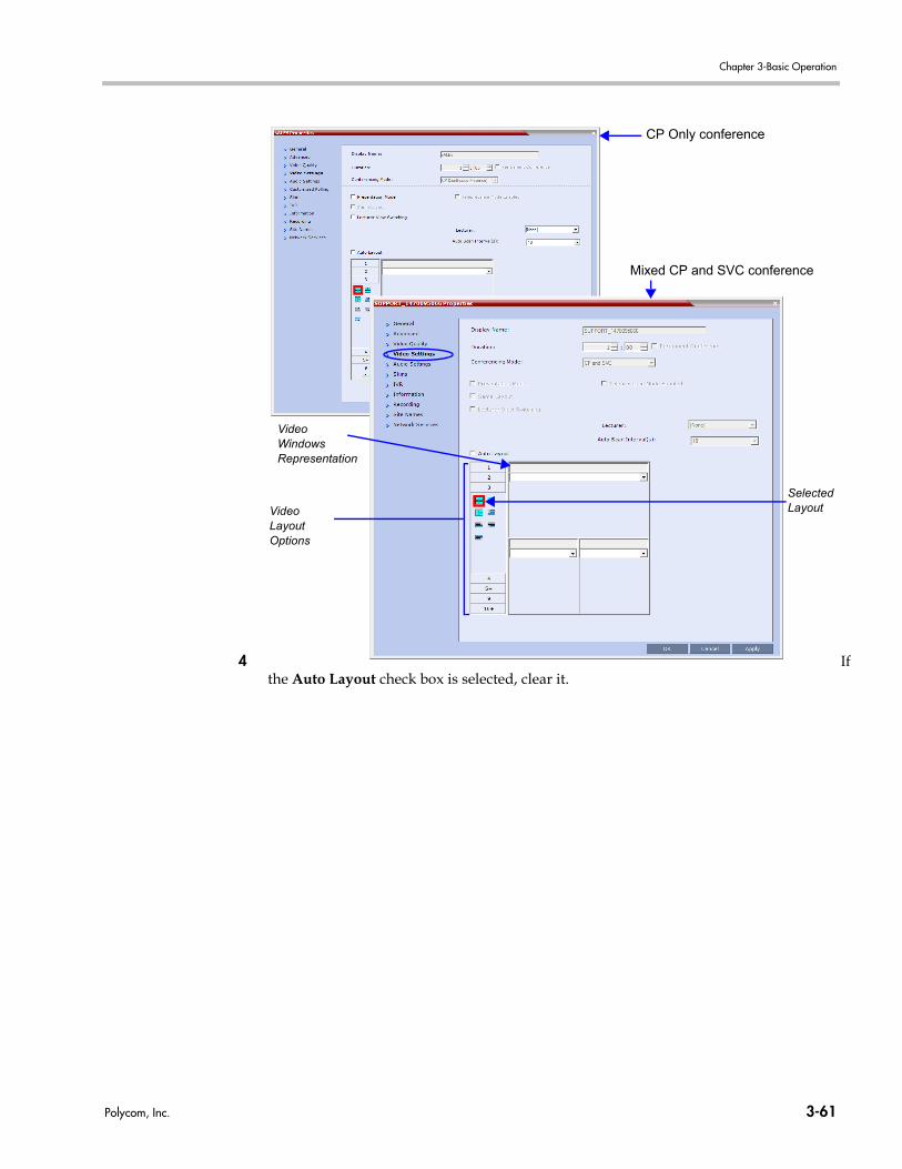
Chapter 3-Basic Operation
4 Ifthe Auto Layout check box is selected, clear it.Video Windows Representation
SelectedLayoutVideo
LayoutOptions
CP Only conference
Mixed CP and SVC conference
Polycom, Inc. 3-61
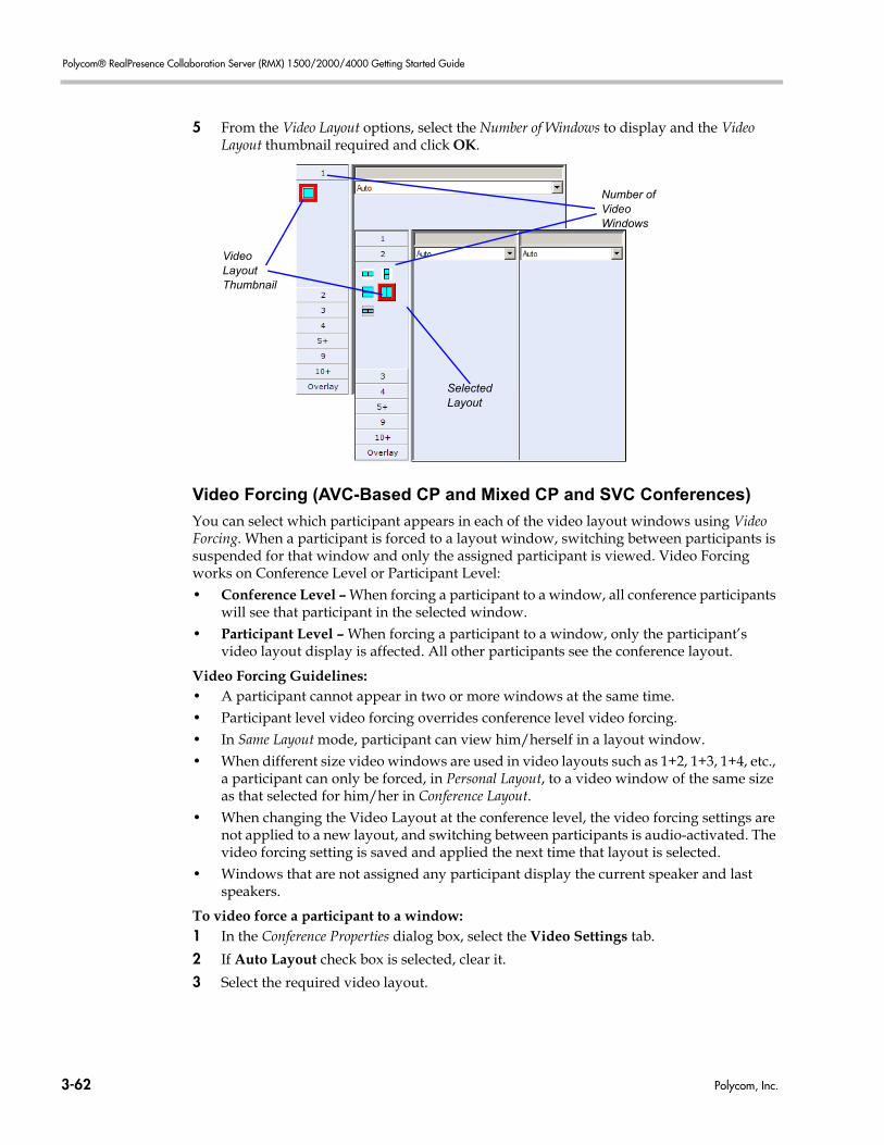
Polycom® RealPresence Collaboration Server (RMX) 1500/2000/4000 Getting Started Guide
5 From the Video Layout options, select the Number of Windows to display and the Video Layout thumbnail required and click OK.
Video Forcing (AVC-Based CP and Mixed CP and SVC Conferences)
You can select which participant appears in each of the video layout windows using Video Forcing. When a participant is forced to a layout window, switching between participants is suspended for that window and only the assigned participant is viewed. Video Forcing works on Conference Level or Participant Level: • Conference Level – When forcing a participant to a window, all conference participants
will see that participant in the selected window.• Participant Level – When forcing a participant to a window, only the participant’s
video layout display is affected. All other participants see the conference layout.
Video Forcing Guidelines: • A participant cannot appear in two or more windows at the same time.• Participant level video forcing overrides conference level video forcing.• In Same Layout mode, participant can view him/herself in a layout window.• When different size video windows are used in video layouts such as 1+2, 1+3, 1+4, etc.,
a participant can only be forced, in Personal Layout, to a video window of the same size as that selected for him/her in Conference Layout.
• When changing the Video Layout at the conference level, the video forcing settings are not applied to a new layout, and switching between participants is audio-activated. The video forcing setting is saved and applied the next time that layout is selected.
• Windows that are not assigned any participant display the current speaker and last speakers.
To video force a participant to a window: 1 In the Conference Properties dialog box, select the Video Settings tab.
2 If Auto Layout check box is selected, clear it.
3 Select the required video layout.
VideoLayoutThumbnail
Number ofVideoWindows
SelectedLayout
3-62 Polycom, Inc.
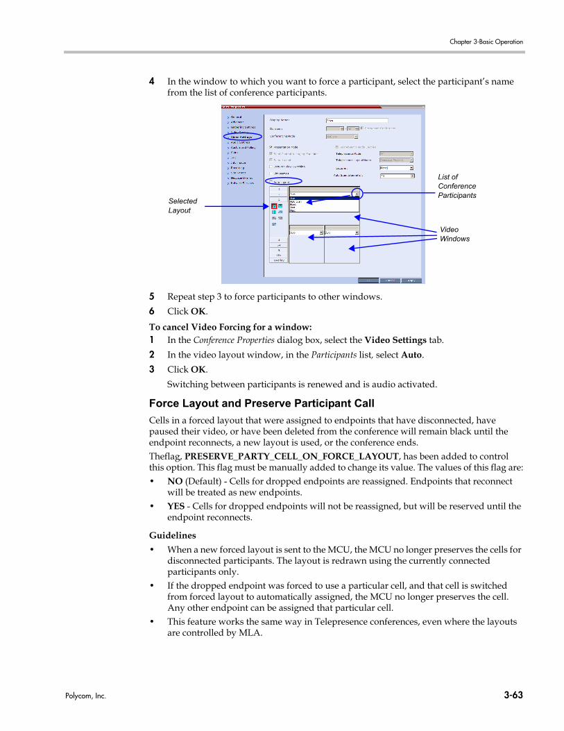
Chapter 3-Basic Operation
4 In the window to which you want to force a participant, select the participant’s name from the list of conference participants.
5 Repeat step 3 to force participants to other windows.
6 Click OK.
To cancel Video Forcing for a window:1 In the Conference Properties dialog box, select the Video Settings tab.
2 In the video layout window, in the Participants list, select Auto.
3 Click OK.
Switching between participants is renewed and is audio activated.
Force Layout and Preserve Participant Call
Cells in a forced layout that were assigned to endpoints that have disconnected, have paused their video, or have been deleted from the conference will remain black until the endpoint reconnects, a new layout is used, or the conference ends.Theflag, PRESERVE_PARTY_CELL_ON_FORCE_LAYOUT, has been added to control this option. This flag must be manually added to change its value. The values of this flag are:• NO (Default) - Cells for dropped endpoints are reassigned. Endpoints that reconnect
will be treated as new endpoints.• YES - Cells for dropped endpoints will not be reassigned, but will be reserved until the
endpoint reconnects.
Guidelines
• When a new forced layout is sent to the MCU, the MCU no longer preserves the cells for disconnected participants. The layout is redrawn using the currently connected participants only.
• If the dropped endpoint was forced to use a particular cell, and that cell is switched from forced layout to automatically assigned, the MCU no longer preserves the cell. Any other endpoint can be assigned that particular cell.
• This feature works the same way in Telepresence conferences, even where the layouts are controlled by MLA.
SelectedLayout
List of ConferenceParticipants
VideoWindows
Polycom, Inc. 3-63
Polycom® RealPresence Collaboration Server (RMX) 1500/2000/4000 Getting Started Guide
For more information see the RealPresence Collaboration Server (RMX) 1500/2000/4000 Administrator’s Guide, "Manually Adding and Deleting System Flags” on page 21-12.
Enabling and Disabling Video Clarity™ (AVC-based Conferences)
When enabled (default), Video Clarity applies video enhancing algorithms to incoming video streams of resolutions up to and including SD. Clearer images with sharper edges and higher contrast are sent back to all endpoints at the highest possible resolution supported by each endpoint. Video Clarity™ can disabled during an ongoing conference.
To disable or enable Video Clarity:1 In the Conference List pane, double-click the name of the conference or right-click the
conference name and then click Conference Properties.
2 Click the Video Quality tab.
3 Clear the Video Clarity check box to disable it or select it to enable it as required.
Click OK.
Muting all Participants Except the Lecturer (AVC-Based CP
Conferences)
The Mute Participants Except Lecturer option can be enabled or disabled during the ongoing conference (in addition to its setting in the conference Profile). When enabled, the audio of all participants in the conference except for the lecturer can be automatically muted upon connection to the conference. This prevents other conference participants from accidentally interrupting the lecture, or from a noisy participant affecting the audio quality of the entire conference. Muted participants cannot unmute themselves unless they are unmuted from the Collaboration Server Web Client/RMX Manager.
Guidelines• Both Administrators and Operators (users) are allowed to set the Mute Participants
Except Lecturer option. It can be enabled at any time after the start of the conference to allow the conference participants to converse before the lecturer joins the conference or before they are muted.
• When the Mute Participants Except Lecturer option is enabled:
— The mute indicator on the participant endpoints are not visible because the mute participants was initiated by the MCU. Therefore, it is recommended to inform the participants that their audio is muted by using the Closed Caption or Message Overlay functions.
— If the endpoint of the designated lecturer is muted when the lecturer connects to the conference, the lecturer remains muted until the endpoint has been unmuted.
— When you disconnect a lecturer from the conference or the lecturer leaves the conference, all participants remain muted but are able to view participants in regular video layout until you disable the Mute Participants Except Lecturer option. When you replace a lecturer, the MCU automatically mutes the previous lecturer and unmutes the new lecturer.
• When The Mute Participants Except Lecturer option is disabled during the ongoing conference, all the participants in the conference are unmuted.
• A participant can override the Mute Participants Except Lecturer option by activating the Mute All Except Me option using the appropriate DTMF code, provided the participant has authorization for this operation in the IVR Services properties. The lecturer audio is
3-64 Polycom, Inc.
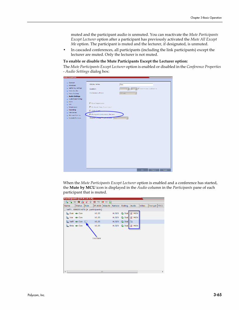
Chapter 3-Basic Operation
muted and the participant audio is unmuted. You can reactivate the Mute Participants Except Lecturer option after a participant has previously activated the Mute All Except Me option. The participant is muted and the lecturer, if designated, is unmuted.
• In cascaded conferences, all participants (including the link participants) except the lecturer are muted. Only the lecturer is not muted.
To enable or disable the Mute Participants Except the Lecturer option:The Mute Participants Except Lecturer option is enabled or disabled in the Conference Properties - Audio Settings dialog box:
When the Mute Participants Except Lecturer option is enabled and a conference has started, the Mute by MCU icon is displayed in the Audio column in the Participants pane of each participant that is muted.
Polycom, Inc. 3-65
Polycom® RealPresence Collaboration Server (RMX) 1500/2000/4000 Getting Started Guide
Sending Messages to All Conference Participants Using Message
Overlay (AVC-based Conferences)
Messages can be sent during a conference to a single participant, selected number of participants or all participants in an ongoing conference. For more information see the RealPresence Collaboration Server (RMX) 1500/2000/4000 Administrator’s Guide "Media Encryption” on page 3-41.
To send messages to all conference participants using Message Overlay:1 In the Conferences List pane, double click the name of the conference to have Message
Overlay enabled or right-click the conference name and then click Conference Properties.
2 Click the Message Overlay tab.
3 Select the Enable check box.
4 In the Content field, enter the text to be displayed to all the conference participants. The number of characters that can be included in a message varies according to the language and can differ due to the type of font used. For example, the available number of characters in Chinese is 32 and 48 for English and Russian.
5 Modify the remaining fields in the dialog box to display the message as required.
6 Click OK.
To cancel the Message Overlay display:1 Repeat Step 1 and Step 2 in the enabling procedure above.
2 Clear the Enable check box.
3 Click OK.
Auto Scan (AVC-based CP Only Conferences)
Auto Scan enables a user to define a single cell in the conference layout to cycle the display of participants that are not in the conference layout.Customized Polling allows the cyclic display to be set to a predefined order for a predefined time period. The cyclic display only occurs when the number of participants is larger than the number of cells in the layout.
To enable Auto Scan:1 In the Collaboration Server Web Client Main Screen - Conference list pane, double-click the
conference or right-click the conference and then click Conference Properties.
2 In the Conference Properties - General dialog box, click Video Settings.The Video Settings tab is displayed.
When sending text messages using Message Overlay and stopping the text messaging in the middle, you must change (and then cancel the change) one of the message overlay properties in the Conference Properties - Message Overlay dialog box before you can re-send the same message.
3-66 Polycom, Inc.
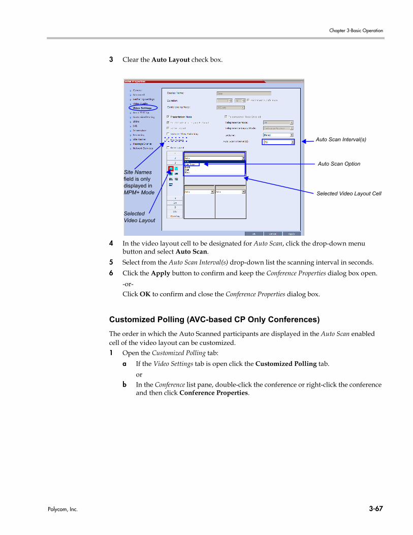
Chapter 3-Basic Operation
3 Clear the Auto Layout check box.
4 In the video layout cell to be designated for Auto Scan, click the drop-down menu button and select Auto Scan.
5 Select from the Auto Scan Interval(s) drop-down list the scanning interval in seconds.
6 Click the Apply button to confirm and keep the Conference Properties dialog box open.
-or-Click OK to confirm and close the Conference Properties dialog box.
Customized Polling (AVC-based CP Only Conferences)
The order in which the Auto Scanned participants are displayed in the Auto Scan enabled cell of the video layout can be customized.1 Open the Customized Polling tab:
a If the Video Settings tab is open click the Customized Polling tab.
orb In the Conference list pane, double-click the conference or right-click the conference
and then click Conference Properties.
Selected Video Layout Cell
Auto Scan Option
SelectedVideo Layout
Auto Scan Interval(s)
Site Names field is only displayed in MPM+ Mode
Polycom, Inc. 3-67

Polycom® RealPresence Collaboration Server (RMX) 1500/2000/4000 Getting Started Guide
c In the Conference Properties - General dialog box, click Customized Polling.The Customized Polling tab is displayed.
All conference participants are listed in the left pane (All Participants) while the participants that are to be displayed in the Auto Scan enabled cell of the video layout are listed in the right pane (Scanning Order).The dialog box buttons are summarized in Table 3-8.
All Conference Participants Scanning Order
Move participant up in Scanning Order
Move participant down in Scanning Order
Add /Delete Add All /
Delete All
Table 3-8 Customized Polling - Buttons
Button Description
Add Select a participant and click this button to Add a the participant to the list of participants to be Auto Scanned.The participants name is removed from the All Participants pane.
Delete Select a participant and click this button to Delete the participant from the list of participants to be Auto Scanned.The participants name is moved back to the All Participants pane.
Add All Add all participants to the list of participants to be Auto Scanned.All participants’ names are removed from the All Participants pane.
Delete All Delete all participant from the list of participants to be Auto Scanned.All participants’ names are moved back to the All Participants pane.
Up Select a participant and click this button to move the participant Up in the Scanning Order.
3-68 Polycom, Inc.
Chapter 3-Basic Operation
2 Optional. Add a participant to the list of participants to be Auto Scanned:
a Click on the participant’s name in the All Participants list.
b Click the Add button to move the participant to the Scanning Order pane.
3 Optional. Delete a participant from the list of participants to be Auto Scanned:
a Click on a participant’s name in the Scanning Order list.
b Click the Delete button to move the participant back to the All Participants pane.
4 Optional. Add all participants to the list of participants to be Auto Scanned:
— Click the Add All button. 5 Optional. Delete all participant from the list of participants to be Auto Scanned:
— Click the Delete All button.6 Optional. Move the participant up in the Scanning Order:
— Click the Up button.7 Optional. Move the participant down in the Scanning Order:
— Click the Down button.8 Click the Apply button to confirm and keep the Conference Properties dialog box open.
or Click the OK the button to confirm and return to the Collaboration Server Web Client Main Screen.
Sending Text Messages to All Participants Using Message Overlay (AVC-based Conferences)
Text messages can be sent to all participant in the conference using the Message Overlayoptions in the Conference Properties – Message Overlay dialog box.To send text messages to all participants in a conference using Message Overlay:1 In the Conferences List pane, double-click the conference entry or right-click the
conference entry and then click Conference Properties. The Conference Properties – General dialog box is displayed.
Down Select a participant and click this button to move the participant Down in the Scanning Order.
Table 3-8 Customized Polling - Buttons
Button Description
Polycom, Inc. 3-69
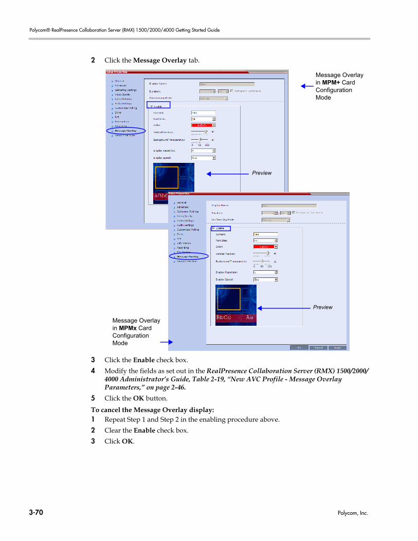
Polycom® RealPresence Collaboration Server (RMX) 1500/2000/4000 Getting Started Guide
2 Click the Message Overlay tab.
3 Click the Enable check box.
4 Modify the fields as set out in the RealPresence Collaboration Server (RMX) 1500/2000/4000 Administrator’s Guide, Table 2-19, “New AVC Profile - Message Overlay Parameters,” on page 2-46.
5 Click the OK button.
To cancel the Message Overlay display:1 Repeat Step 1 and Step 2 in the enabling procedure above.
2 Clear the Enable check box.
3 Click OK.
Preview
Preview
Message Overlay in MPM+ Card Configuration Mode
Message Overlay in MPMx Card Configuration Mode
3-70 Polycom, Inc.
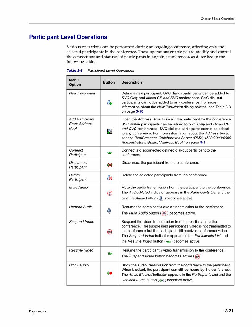
Chapter 3-Basic Operation
Participant Level Operations
Various operations can be performed during an ongoing conference, affecting only the selected participants in the conference. These operations enable you to modify and control the connections and statuses of participants in ongoing conferences, as described in the following table:
Table 3-9 Participant Level Operations
MenuOption
Button Description
New Participant Define a new participant. SVC dial-in participants can be added to SVC Only and Mixed CP and SVC conferences. SVC dial-out participants cannot be added to any conference. For more information about the New Participant dialog box tab, see Table 3-3 on page 3-18.
Add Participant From Address Book
Open the Address Book to select the participant for the conference.SVC dial-in participants can be added to SVC Only and Mixed CP and SVC conferences. SVC dial-out participants cannot be added to any conference. For more information about the Address Book, see the RealPresence Collaboration Server (RMX) 1500/2000/4000 Administrator’s Guide, "Address Book” on page 8-1.
Connect Participant
Connect a disconnected defined dial-out participant to the conference.
Disconnect Participant
Disconnect the participant from the conference.
Delete Participant
Delete the selected participants from the conference.
Mute Audio Mute the audio transmission from the participant to the conference.The Audio Muted indicator appears in the Participants List and the
Unmute Audio button ( ) becomes active.
Unmute Audio Resume the participant’s audio transmission to the conference.
The Mute Audio button ( ) becomes active.
Suspend Video Suspend the video transmission from the participant to the conference. The suppressed participant’s video is not transmitted to the conference but the participant still receives conference video.The Suspend Video indicator appears in the Participants List and
the Resume Video button ( ) becomes active.
Resume Video Resume the participant’s video transmission to the conference.
The Suspend Video button becomes active ( ).
Block Audio Block the audio transmission from the conference to the participant. When blocked, the participant can still be heard by the conference.The Audio Blocked indicator appears in the Participants List and the
Unblock Audio button ( ) becomes active.
Polycom, Inc. 3-71
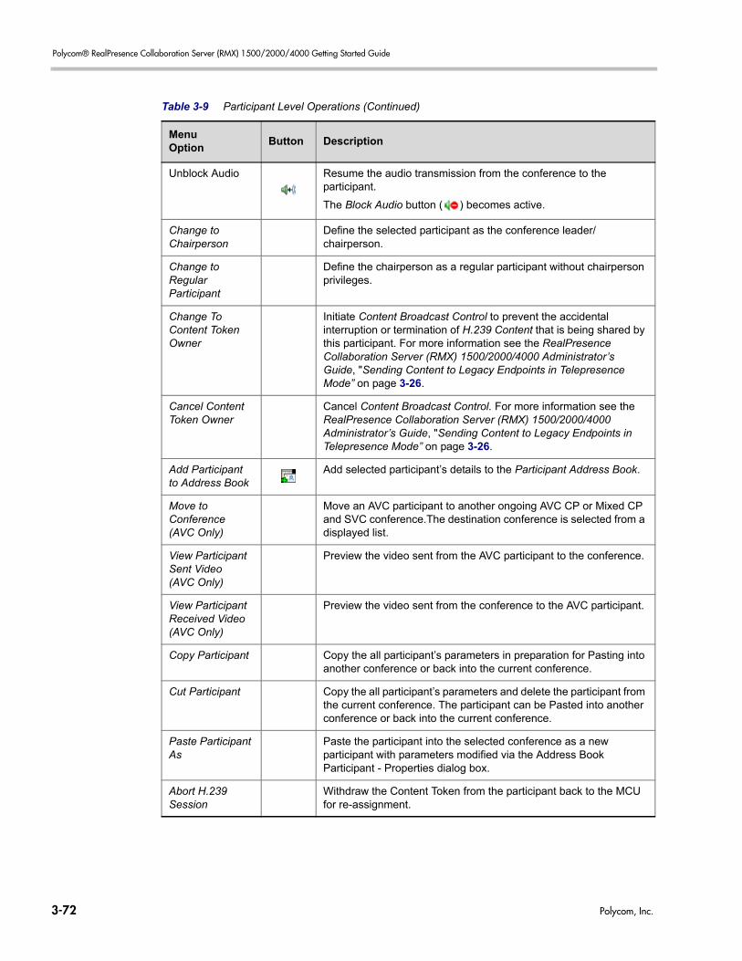
Polycom® RealPresence Collaboration Server (RMX) 1500/2000/4000 Getting Started Guide
Unblock Audio Resume the audio transmission from the conference to the participant.
The Block Audio button ( ) becomes active.
Change to Chairperson
Define the selected participant as the conference leader/chairperson.
Change to Regular Participant
Define the chairperson as a regular participant without chairperson privileges.
Change To Content Token Owner
Initiate Content Broadcast Control to prevent the accidental interruption or termination of H.239 Content that is being shared by this participant. For more information see the RealPresence Collaboration Server (RMX) 1500/2000/4000 Administrator’s Guide, "Sending Content to Legacy Endpoints in Telepresence Mode” on page 3-26.
Cancel Content Token Owner
Cancel Content Broadcast Control. For more information see the RealPresence Collaboration Server (RMX) 1500/2000/4000 Administrator’s Guide, "Sending Content to Legacy Endpoints in Telepresence Mode” on page 3-26.
Add Participant to Address Book
Add selected participant’s details to the Participant Address Book.
Move to Conference (AVC Only)
Move an AVC participant to another ongoing AVC CP or Mixed CP and SVC conference.The destination conference is selected from a displayed list.
View Participant Sent Video (AVC Only)
Preview the video sent from the AVC participant to the conference.
View Participant Received Video(AVC Only)
Preview the video sent from the conference to the AVC participant.
Copy Participant Copy the all participant’s parameters in preparation for Pasting into another conference or back into the current conference.
Cut Participant Copy the all participant’s parameters and delete the participant from the current conference. The participant can be Pasted into another conference or back into the current conference.
Paste Participant As
Paste the participant into the selected conference as a new participant with parameters modified via the Address Book Participant - Properties dialog box.
Abort H.239 Session
Withdraw the Content Token from the participant back to the MCU for re-assignment.
Table 3-9 Participant Level Operations (Continued)
MenuOption
Button Description
3-72 Polycom, Inc.
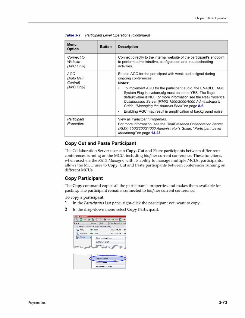
Chapter 3-Basic Operation
Copy Cut and Paste Participant
The Collaboration Server user can Copy, Cut and Paste participants between differ rent conferences running on the MCU, including his/her current conference. These functions, when used via the RMX Manager, with its ability to manage multiple MCUs, participants, allows the MCU user to Copy, Cut and Paste participants between conferences running on different MCUs.
Copy Participant
The Copy command copies all the participant’s properties and makes them available for pasting. The participant remains connected to his/her current conference.
To copy a participant:1 In the Participants List pane, right-click the participant you want to copy.
2 In the drop-down menu select Copy Participant.
Connect to Website (AVC Only)
Connect directly to the internal website of the participant’s endpoint to perform administrative, configuration and troubleshooting activities.
AGC(Auto Gain Control)(AVC Only)
Enable AGC for the participant with weak audio signal during ongoing conferences.Notes:
• To implement AGC for the participant audio, the ENABLE_AGC System Flag in system.cfg must be set to YES. The flag’s default value is NO. For more information see the RealPresence Collaboration Server (RMX) 1500/2000/4000 Administrator’s Guide, "Managing the Address Book” on page 8-6.
• Enabling AGC may result in amplification of background noise.
Participant Properties
View all Participant Properties. For more information, see the RealPresence Collaboration Server (RMX) 1500/2000/4000 Administrator’s Guide, "Participant Level Monitoring” on page 13-23.
Table 3-9 Participant Level Operations (Continued)
MenuOption
Button Description
Polycom, Inc. 3-73
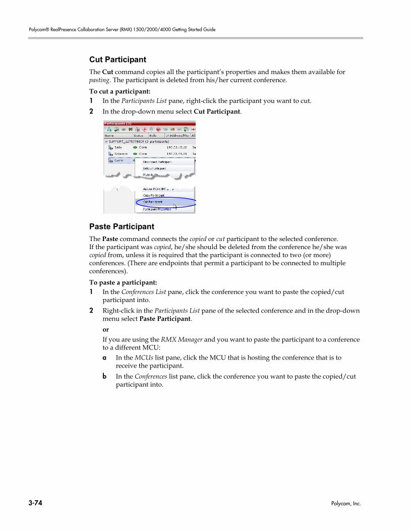
Polycom® RealPresence Collaboration Server (RMX) 1500/2000/4000 Getting Started Guide
Cut Participant
The Cut command copies all the participant’s properties and makes them available for pasting. The participant is deleted from his/her current conference.
To cut a participant:1 In the Participants List pane, right-click the participant you want to cut.
2 In the drop-down menu select Cut Participant.
Paste Participant
The Paste command connects the copied or cut participant to the selected conference.If the participant was copied, he/she should be deleted from the conference he/she was copied from, unless it is required that the participant is connected to two (or more) conferences. (There are endpoints that permit a participant to be connected to multiple conferences).
To paste a participant:1 In the Conferences List pane, click the conference you want to paste the copied/cut
participant into.
2 Right-click in the Participants List pane of the selected conference and in the drop-down menu select Paste Participant.
orIf you are using the RMX Manager and you want to paste the participant to a conference to a different MCU:a In the MCUs list pane, click the MCU that is hosting the conference that is to
receive the participant.
b In the Conferences list pane, click the conference you want to paste the copied/cut participant into.
3-74 Polycom, Inc.
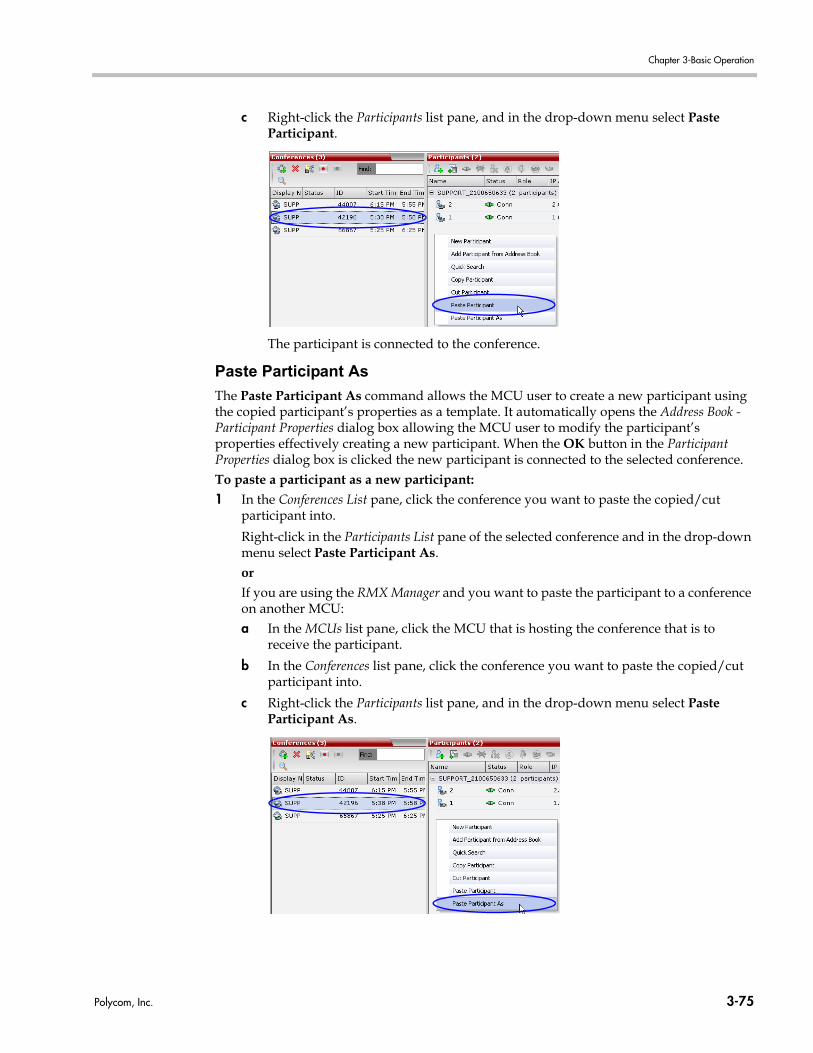
Chapter 3-Basic Operation
c Right-click the Participants list pane, and in the drop-down menu select Paste Participant.
The participant is connected to the conference.
Paste Participant As
The Paste Participant As command allows the MCU user to create a new participant using the copied participant’s properties as a template. It automatically opens the Address Book - Participant Properties dialog box allowing the MCU user to modify the participant’s properties effectively creating a new participant. When the OK button in the Participant Properties dialog box is clicked the new participant is connected to the selected conference.To paste a participant as a new participant:1 In the Conferences List pane, click the conference you want to paste the copied/cut
participant into.
Right-click in the Participants List pane of the selected conference and in the drop-down menu select Paste Participant As.orIf you are using the RMX Manager and you want to paste the participant to a conference on another MCU:a In the MCUs list pane, click the MCU that is hosting the conference that is to
receive the participant.
b In the Conferences list pane, click the conference you want to paste the copied/cut participant into.
c Right-click the Participants list pane, and in the drop-down menu select Paste Participant As.
Polycom, Inc. 3-75
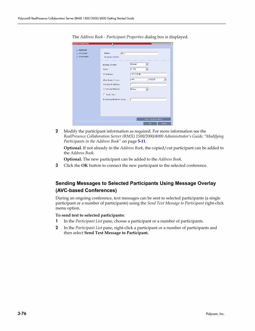
Polycom® RealPresence Collaboration Server (RMX) 1500/2000/4000 Getting Started Guide
The Address Book - Participant Properties dialog box is displayed.
2 Modify the participant information as required. For more information see theRealPresence Collaboration Server (RMX) 1500/2000/4000 Administrator’s Guide, "Modifying Participants in the Address Book” on page 5-11.
Optional. If not already in the Address Book, the copied/cut participant can be added to the Address Book.Optional. The new participant can be added to the Address Book.
3 Click the OK button to connect the new participant to the selected conference.
Sending Messages to Selected Participants Using Message Overlay
(AVC-based Conferences)
During an ongoing conference, text messages can be sent to selected participants (a single participant or a number of participants) using the Send Text Message to Participant right-click menu option.
To send text to selected participants:1 In the Participant List pane, choose a participant or a number of participants.
2 In the Participant List pane, right-click a participant or a number of participants and then select Send Text Message to Participant.
3-76 Polycom, Inc.
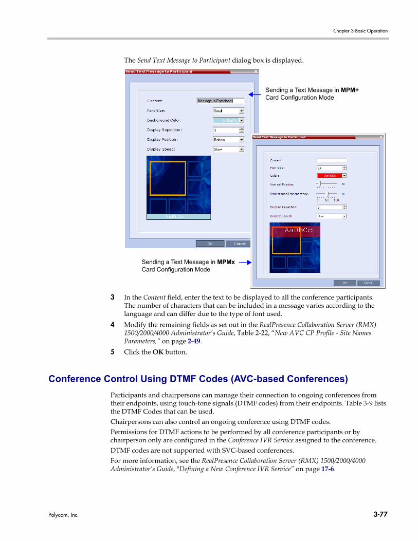
Chapter 3-Basic Operation
The Send Text Message to Participant dialog box is displayed.
3 In the Content field, enter the text to be displayed to all the conference participants. The number of characters that can be included in a message varies according to the language and can differ due to the type of font used.
4 Modify the remaining fields as set out in the RealPresence Collaboration Server (RMX) 1500/2000/4000 Administrator’s Guide, Table 2-22, “New AVC CP Profile - Site Names Parameters,” on page 2-49.
5 Click the OK button.
Conference Control Using DTMF Codes (AVC-based Conferences)
Participants and chairpersons can manage their connection to ongoing conferences from their endpoints, using touch-tone signals (DTMF codes) from their endpoints. Table 3-9 lists the DTMF Codes that can be used. Chairpersons can also control an ongoing conference using DTMF codes.Permissions for DTMF actions to be performed by all conference participants or by chairperson only are configured in the Conference IVR Service assigned to the conference. DTMF codes are not supported with SVC-based conferences.For more information, see the RealPresence Collaboration Server (RMX) 1500/2000/4000 Administrator’s Guide, "Defining a New Conference IVR Service” on page 17-6.
Sending a Text Message in MPM+ Card Configuration Mode
Sending a Text Message in MPMx Card Configuration Mode
Polycom, Inc. 3-77
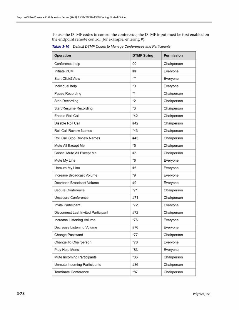
Polycom® RealPresence Collaboration Server (RMX) 1500/2000/4000 Getting Started Guide
To use the DTMF codes to control the conference, the DTMF input must be first enabled on the endpoint remote control (for example, entering #).
Table 3-10 Default DTMF Codes to Manage Conferences and Participants
Operation DTMF String Permission
Conference help 00 Chairperson
Initiate PCM ## Everyone
Start Click&View ** Everyone
Individual help *0 Everyone
Pause Recording *1 Chairperson
Stop Recording *2 Chairperson
Start/Resume Recording *3 Chairperson
Enable Roll Call *42 Chairperson
Disable Roll Call #42 Chairperson
Roll Call Review Names *43 Chairperson
Roll Call Stop Review Names #43 Chairperson
Mute All Except Me *5 Chairperson
Cancel Mute All Except Me #5 Chairperson
Mute My Line *6 Everyone
Unmute My Line #6 Everyone
Increase Broadcast Volume *9 Everyone
Decrease Broadcast Volume #9 Everyone
Secure Conference *71 Chairperson
Unsecure Conference #71 Chairperson
Invite Participant *72 Everyone
Disconnect Last Invited Participant #72 Chairperson
Increase Listening Volume *76 Everyone
Decrease Listening Volume #76 Everyone
Change Password *77 Chairperson
Change To Chairperson *78 Everyone
Play Help Menu *83 Everyone
Mute Incoming Participants *86 Chairperson
Unmute Incoming Participants #86 Chairperson
Terminate Conference *87 Chairperson
3-78 Polycom, Inc.
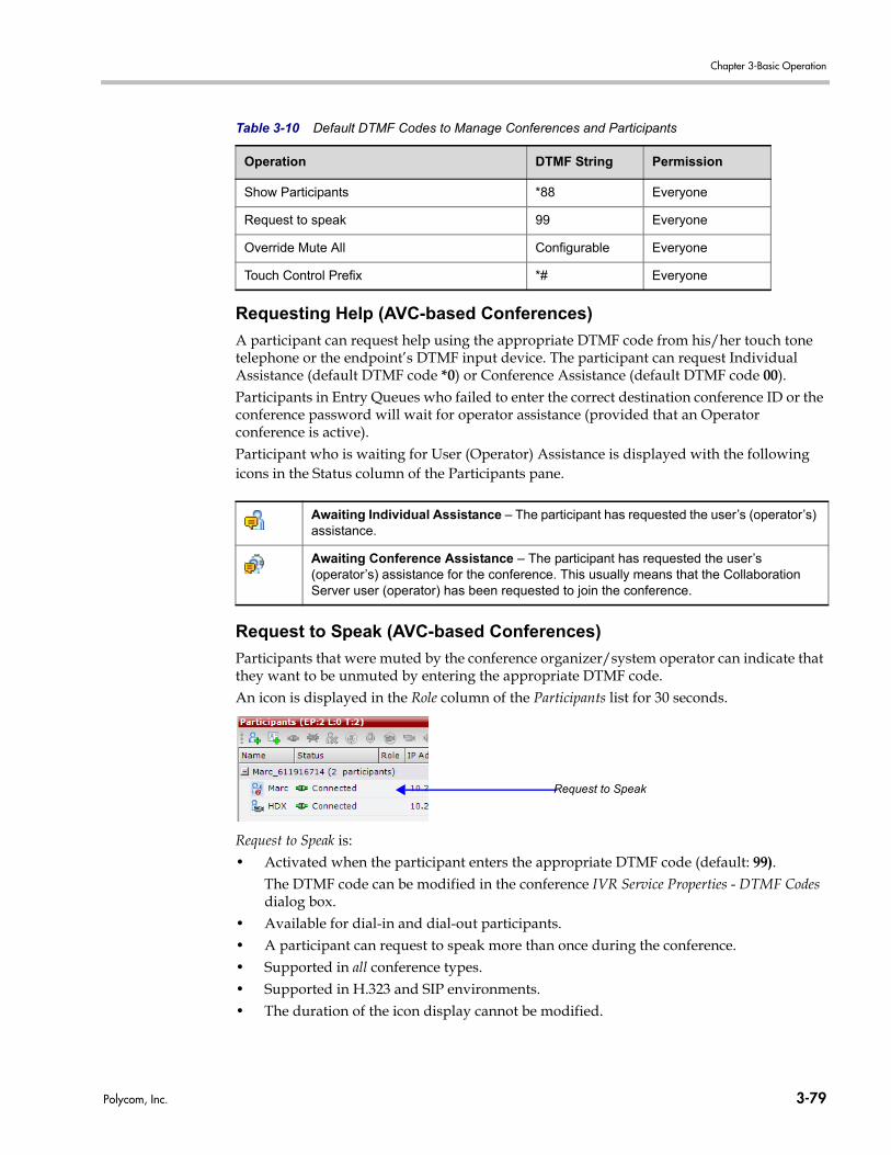
Chapter 3-Basic Operation
Requesting Help (AVC-based Conferences)
A participant can request help using the appropriate DTMF code from his/her touch tone telephone or the endpoint’s DTMF input device. The participant can request Individual Assistance (default DTMF code *0) or Conference Assistance (default DTMF code 00).Participants in Entry Queues who failed to enter the correct destination conference ID or the conference password will wait for operator assistance (provided that an Operator conference is active).Participant who is waiting for User (Operator) Assistance is displayed with the following icons in the Status column of the Participants pane.
Request to Speak (AVC-based Conferences)
Participants that were muted by the conference organizer/system operator can indicate that they want to be unmuted by entering the appropriate DTMF code.An icon is displayed in the Role column of the Participants list for 30 seconds.
Request to Speak is:• Activated when the participant enters the appropriate DTMF code (default: 99).
The DTMF code can be modified in the conference IVR Service Properties - DTMF Codes dialog box.
• Available for dial-in and dial-out participants.• A participant can request to speak more than once during the conference.• Supported in all conference types.• Supported in H.323 and SIP environments.• The duration of the icon display cannot be modified.
Show Participants *88 Everyone
Request to speak 99 Everyone
Override Mute All Configurable Everyone
Touch Control Prefix *# Everyone
Awaiting Individual Assistance – The participant has requested the user’s (operator’s) assistance.
Awaiting Conference Assistance – The participant has requested the user’s (operator’s) assistance for the conference. This usually means that the Collaboration Server user (operator) has been requested to join the conference.
Table 3-10 Default DTMF Codes to Manage Conferences and Participants
Operation DTMF String Permission
Request to Speak
Polycom, Inc. 3-79
Polycom® RealPresence Collaboration Server (RMX) 1500/2000/4000 Getting Started Guide
Invite Participant (AVC-based Conferences)
A participant in a video or audio conference can invite another participant to the conference using the touch-tone DTMF numeric keypad on the participant’s endpoint. You can invite a participant using various communication devices, such as a mobile phone, an IP phone, PSTN phones, laptops, or connect to another conference running on another PBX or MCU.
Invite Call Flow
The following flow describes how a participant is invited to the conference using the DTMF codes:1 During the conference, the participant enters the DTMF code (default is *72) on the
numeric keypad to invite another participant.
2 The participant is prompted to enter the invited participant’s destination number (a number or IP address) including the prefix (if required) and the DTMF delimiter digit (‘*’ or ‘#’) at the end. The asterisk (‘*’) is used to denote the dot in the IP address.
For example: To enter an IP address such as 10.245.22.19, on the DTMF keypad press 10*245*22*19 and then the DTMF delimiter.
3 The system automatically dials to the destination according to the protocol order as defined in the IVR Services Properties - Video Services tab.
When the call cannot be completed by the current protocol, the system attempts to connect to the destination using the next protocol according to the protocol order.The RMX connects the participant when the call is answered.
Entering Additional DTMF Codes
In some environments, the call is answered by an IVR system (for example when connecting to another conference or PBX), requesting a password or a destination number to complete the connection process. In such a case, additional DTMF digits must be entered before the DTMF forward duration time has expired and are forwarded to the invited destination. When the additional DTMF codes are entered, they are heard by all the conference participants.If the DTMF code is not entered on time or if the wrong DTMF code is entered, the participant is prompted for a new input. After the defined number of retries have elapsed, the call is ended.
Error Handling
• If the destination endpoint is busy or the participant did not answer, the system ends the call.
• When an incorrect number is entered, the call fails and an error message is displayed.• If the destination number is not entered in a specific amount of time (defined in
Timeout for user input in the IVR Services - Global tab), the participant is prompted to enter a destination number again. Depending on the Number of user input retries as defined in the IVR Services - Global tab, the system will attempt to receive the required input. When all the retries have failed, the call to the invited participant is cancelled.
Guidelines
• In CP conferences, the participant initiating the invitation to another participant is able to view the dialing information and connection status. During the dialing process, the
Digits that are entered after the DTMF delimiter and before the participant is connected are ignored.
3-80 Polycom, Inc.
Chapter 3-Basic Operation
dialing string is displayed as the participant name which is replaced by the site name when connected to the conference.
• By default, all participants (Everyone) are granted permission to invite a participant to join a conference. To change the permission to the Chairperson, modify the Permission column in the IVR Service - DTMF Codes tab.
For details on enabling the Invite Participants feature, see "Inviting Participants using DTMF” on page 17-35.
Personal Conference Manager (PCM) (AVC-based Conferences)
The Personal Conference Manager (PCM) interface enables the conference chairperson to control various conference features using his/her endpoint’s remote control device.The following conference operations can be performed:• Initiate Polycom’s Click&View™ application to change the local screen layout.• Invite participants to connect to the conference.• View and control the audio and video of each connected endpoint.• Camera Control - control the camera of a remote endpoint using Far End Camera Control
(FECC).• Control the camera of a connected endpoint.• Video Force a specific participant to a specific window of the video layout.• Initiate and control recording of the conference.• Disconnect a participant.• Terminate the conference.
Guidelines
• PCM is supported with MPM+ and MPMx cards.• PCM is supported in H.323 and SIP network environments.• PCM is only available in AVC-based conferences. • PCM is only available in CP and Event Mode conferences.• Although the RMX can host up to a maximum of 800 conferences (depending on the
RMX model) PCM can only be activated from 4 conferences per MPM+ or MPMx media card.— An RMX 2000 with 2 MPM+ or 2 MPMxmedia cards installed can host a total of 8
PCM sessions while an RMX 4000 with 4 MPM+ or 4 MPMx media cards installed can host a total of 16 PCM sessions.
— If 4 PCM sessions are active on an MPM+ /MPMx media card and a chairperson of another conference, hosted on the same MPM+/MPMx media card, attempts to start an additional PCM session, a message is displayed indicating that the requested PCM session cannot be activated because the maximum number of concurrent PCM sessions are already activated. FECC is then activated.
— When PCM is active, FECC can only be performed by the chairperson using PCM’s Camera Control menu.
Licensing Mode
CP EM
Polycom, Inc. 3-81
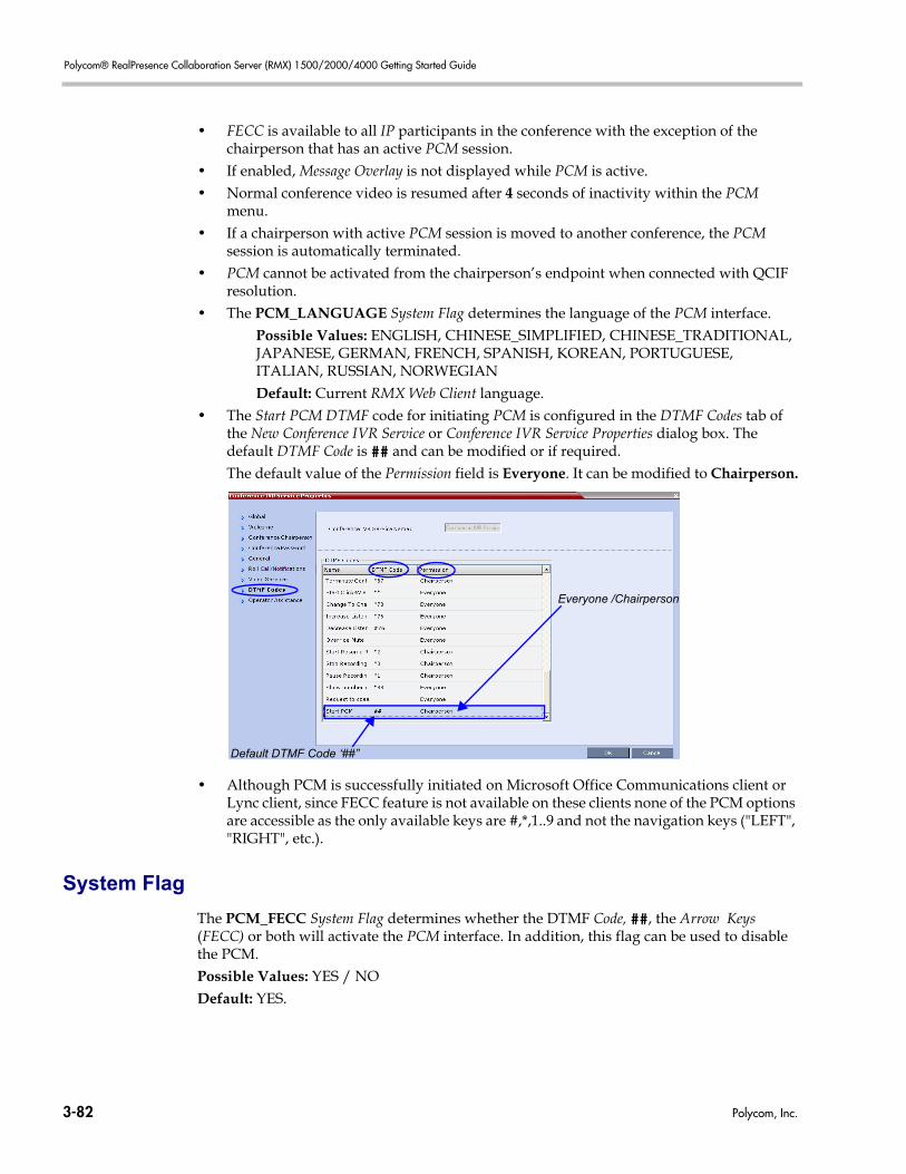
Polycom® RealPresence Collaboration Server (RMX) 1500/2000/4000 Getting Started Guide
• FECC is available to all IP participants in the conference with the exception of the chairperson that has an active PCM session.
• If enabled, Message Overlay is not displayed while PCM is active.• Normal conference video is resumed after 4 seconds of inactivity within the PCM
menu.• If a chairperson with active PCM session is moved to another conference, the PCM
session is automatically terminated.• PCM cannot be activated from the chairperson’s endpoint when connected with QCIF
resolution.• The PCM_LANGUAGE System Flag determines the language of the PCM interface.
Possible Values: ENGLISH, CHINESE_SIMPLIFIED, CHINESE_TRADITIONAL, JAPANESE, GERMAN, FRENCH, SPANISH, KOREAN, PORTUGUESE, ITALIAN, RUSSIAN, NORWEGIANDefault: Current RMX Web Client language.
• The Start PCM DTMF code for initiating PCM is configured in the DTMF Codes tab of the New Conference IVR Service or Conference IVR Service Properties dialog box. The default DTMF Code is ## and can be modified or if required.The default value of the Permission field is Everyone. It can be modified to Chairperson.
• Although PCM is successfully initiated on Microsoft Office Communications client or Lync client, since FECC feature is not available on these clients none of the PCM options are accessible as the only available keys are #,*,1..9 and not the navigation keys ("LEFT", "RIGHT", etc.).
System Flag
The PCM_FECC System Flag determines whether the DTMF Code, ##, the Arrow Keys (FECC) or both will activate the PCM interface. In addition, this flag can be used to disable the PCM.Possible Values: YES / NO Default: YES.
Everyone /Chairperson
Default DTMF Code ‘##”
3-82 Polycom, Inc.
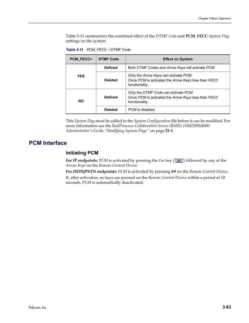
Chapter 3-Basic Operation
Table 3-11 summarizes the combined effect of the DTMF Code and PCM_FECC System Flag settings on the system.
This System Flag must be added to the System Configuration file before it can be modified. For more information see the RealPresence Collaboration Server (RMX) 1500/2000/4000 Administrator’s Guide, "Modifying System Flags” on page 21-1.
PCM Interface
Initiating PCM
For IP endpoints: PCM is activated by pressing the Far key ( ) followed by any of the Arrow Keys on the Remote Control Device.For ISDN/PSTN endpoints: PCM is activated by pressing ## on the Remote Control Device.If, after activation, no keys are pressed on the Remote Control Device within a period of 10 seconds, PCM is automatically deactivated.
Table 3-11 PCM_FECC / DTMF Code
PCM_FECC= DTMF Code Effect on System
YES
Defined Both DTMF Codes and Arrow Keys will activate PCM.
DeletedOnly the Arrow Keys can activate PCM.Once PCM is activated the Arrow Keys lose their FECC functionality.
NODefined
Only the DTMF Code can activate PCM.Once PCM is activated the Arrow Keys lose their FECC functionality.
Deleted PCM is disabled.
Polycom, Inc. 3-83
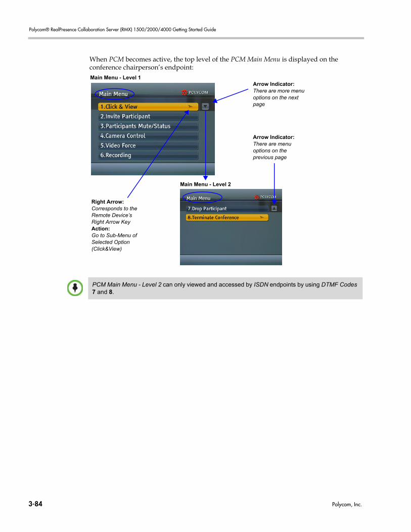
Polycom® RealPresence Collaboration Server (RMX) 1500/2000/4000 Getting Started Guide
When PCM becomes active, the top level of the PCM Main Menu is displayed on the conference chairperson’s endpoint:
Arrow Indicator: There are more menu options on the next page
Right Arrow: Corresponds to the Remote Device’s Right Arrow KeyAction: Go to Sub-Menu ofSelected Option(Click&View)
Main Menu - Level 1
Arrow Indicator: There are menu options on the previous page
Main Menu - Level 2
PCM Main Menu - Level 2 can only viewed and accessed by ISDN endpoints by using DTMF Codes 7 and 8.
3-84 Polycom, Inc.
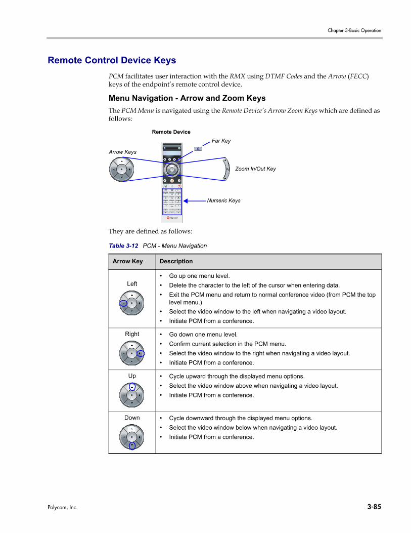
Chapter 3-Basic Operation
Remote Control Device Keys
PCM facilitates user interaction with the RMX using DTMF Codes and the Arrow (FECC) keys of the endpoint’s remote control device.
Menu Navigation - Arrow and Zoom Keys
The PCM Menu is navigated using the Remote Device’s Arrow Zoom Keys which are defined as follows:
They are defined as follows:
Table 3-12 PCM - Menu Navigation
Arrow Key Description
Left• Go up one menu level.
• Delete the character to the left of the cursor when entering data.
• Exit the PCM menu and return to normal conference video (from PCM the top level menu.)
• Select the video window to the left when navigating a video layout.
• Initiate PCM from a conference.
Right • Go down one menu level.
• Confirm current selection in the PCM menu.
• Select the video window to the right when navigating a video layout.
• Initiate PCM from a conference.
Up • Cycle upward through the displayed menu options.
• Select the video window above when navigating a video layout.
• Initiate PCM from a conference.
Down • Cycle downward through the displayed menu options.
• Select the video window below when navigating a video layout.
• Initiate PCM from a conference.
Arrow Keys
Zoom In/Out Key
Remote Device
Numeric Keys
Far Key
Polycom, Inc. 3-85
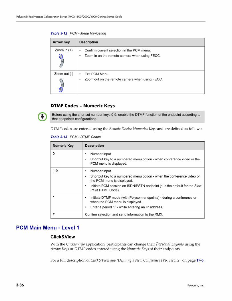
Polycom® RealPresence Collaboration Server (RMX) 1500/2000/4000 Getting Started Guide
DTMF Codes - Numeric Keys
DTMF codes are entered using the Remote Device Numerics Keys and are defined as follows:
PCM Main Menu - Level 1
Click&View
With the Click&View application, participants can change their Personal Layouts using the Arrow Keys or DTMF codes entered using the Numeric Keys of their endpoints.
For a full description of Click&View see "Defining a New Conference IVR Service” on page 17-6.
Zoom in (+) • Confirm current selection in the PCM menu.
• Zoom in on the remote camera when using FECC.
Zoom out (-) • Exit PCM Menu.
• Zoom out on the remote camera when using FECC.
Table 3-12 PCM - Menu Navigation
Arrow Key Description
Before using the shortcut number keys 0-9, enable the DTMF function of the endpoint according to that endpoint’s configurations.
Table 3-13 PCM - DTMF Codes
Numeric Key Description
0 • Number input.
• Shortcut key to a numbered menu option - when conference video or the PCM menu is displayed.
1-9 • Number input.
• Shortcut key to a numbered menu option - when the conference video or the PCM menu is displayed.
• Initiate PCM session on ISDN/PSTN endpoint (1 is the default for the Start PCM DTMF Code).
* • Initiate DTMF mode (with Polycom endpoints) - during a conference or when the PCM menu is displayed.
• Enter a period “.” - while entering an IP address.
# Confirm selection and send information to the RMX.
3-86 Polycom, Inc.
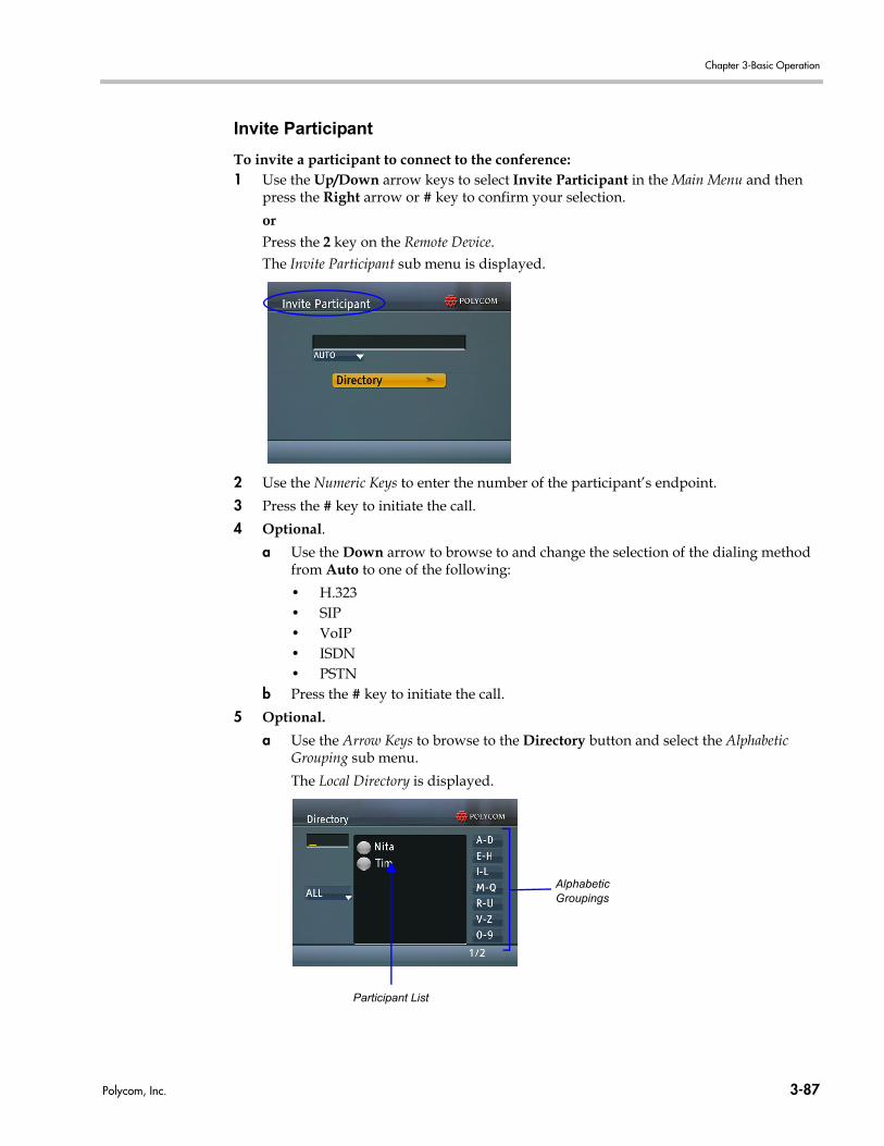
Chapter 3-Basic Operation
Invite Participant
To invite a participant to connect to the conference:1 Use the Up/Down arrow keys to select Invite Participant in the Main Menu and then
press the Right arrow or # key to confirm your selection.
orPress the 2 key on the Remote Device.The Invite Participant sub menu is displayed.
2 Use the Numeric Keys to enter the number of the participant’s endpoint.
3 Press the # key to initiate the call.
4 Optional.
a Use the Down arrow to browse to and change the selection of the dialing method from Auto to one of the following:
• H.323• SIP• VoIP• ISDN• PSTN
b Press the # key to initiate the call.
5 Optional.
a Use the Arrow Keys to browse to the Directory button and select the Alphabetic Grouping sub menu.
The Local Directory is displayed.
Participant List
AlphabeticGroupings
Polycom, Inc. 3-87
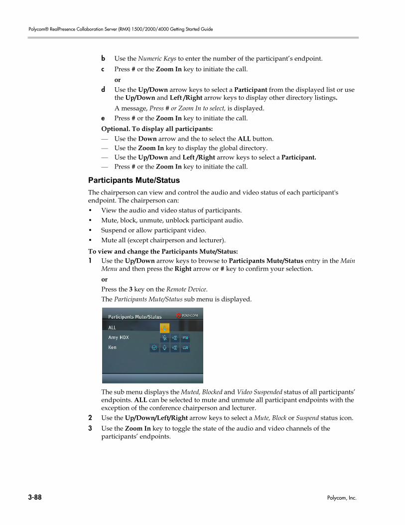
Polycom® RealPresence Collaboration Server (RMX) 1500/2000/4000 Getting Started Guide
b Use the Numeric Keys to enter the number of the participant’s endpoint.
c Press # or the Zoom In key to initiate the call.
ord Use the Up/Down arrow keys to select a Participant from the displayed list or use
the Up/Down and Left /Right arrow keys to display other directory listings.
A message, Press # or Zoom In to select, is displayed. e Press # or the Zoom In key to initiate the call.
Optional. To display all participants:— Use the Down arrow and the to select the ALL button.— Use the Zoom In key to display the global directory.— Use the Up/Down and Left /Right arrow keys to select a Participant.— Press # or the Zoom In key to initiate the call.
Participants Mute/Status
The chairperson can view and control the audio and video status of each participant's endpoint. The chairperson can:• View the audio and video status of participants. • Mute, block, unmute, unblock participant audio.• Suspend or allow participant video.• Mute all (except chairperson and lecturer).
To view and change the Participants Mute/Status:1 Use the Up/Down arrow keys to browse to Participants Mute/Status entry in the Main
Menu and then press the Right arrow or # key to confirm your selection.
orPress the 3 key on the Remote Device.The Participants Mute/Status sub menu is displayed.
The sub menu displays the Muted, Blocked and Video Suspended status of all participants’ endpoints. ALL can be selected to mute and unmute all participant endpoints with the exception of the conference chairperson and lecturer.
2 Use the Up/Down/Left/Right arrow keys to select a Mute, Block or Suspend status icon.
3 Use the Zoom In key to toggle the state of the audio and video channels of the participants’ endpoints.
3-88 Polycom, Inc.
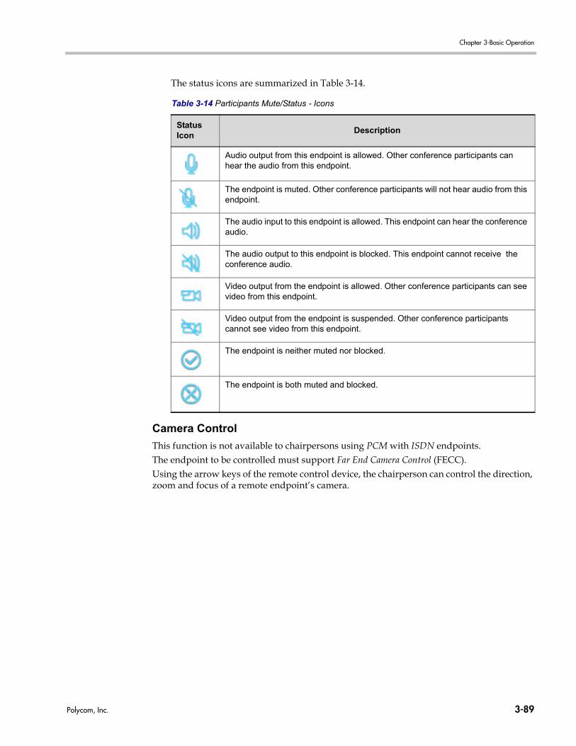
Chapter 3-Basic Operation
The status icons are summarized in Table 3-14.
Camera Control
This function is not available to chairpersons using PCM with ISDN endpoints.The endpoint to be controlled must support Far End Camera Control (FECC).Using the arrow keys of the remote control device, the chairperson can control the direction, zoom and focus of a remote endpoint’s camera.
Table 3-14 Participants Mute/Status - Icons
Status Icon
Description
Audio output from this endpoint is allowed. Other conference participants can hear the audio from this endpoint.
The endpoint is muted. Other conference participants will not hear audio from this endpoint.
The audio input to this endpoint is allowed. This endpoint can hear the conference audio.
The audio output to this endpoint is blocked. This endpoint cannot receive the conference audio.
Video output from the endpoint is allowed. Other conference participants can see video from this endpoint.
Video output from the endpoint is suspended. Other conference participants cannot see video from this endpoint.
The endpoint is neither muted nor blocked.
The endpoint is both muted and blocked.
Polycom, Inc. 3-89
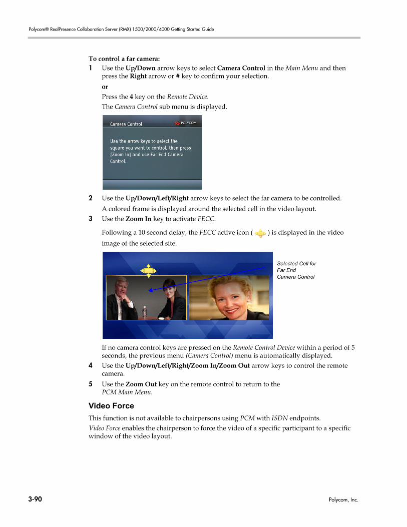
Polycom® RealPresence Collaboration Server (RMX) 1500/2000/4000 Getting Started Guide
To control a far camera:1 Use the Up/Down arrow keys to select Camera Control in the Main Menu and then
press the Right arrow or # key to confirm your selection.
orPress the 4 key on the Remote Device.The Camera Control sub menu is displayed.
2 Use the Up/Down/Left/Right arrow keys to select the far camera to be controlled.
A colored frame is displayed around the selected cell in the video layout.3 Use the Zoom In key to activate FECC.
Following a 10 second delay, the FECC active icon ( ) is displayed in the video
image of the selected site.
If no camera control keys are pressed on the Remote Control Device within a period of 5 seconds, the previous menu (Camera Control) menu is automatically displayed.
4 Use the Up/Down/Left/Right/Zoom In/Zoom Out arrow keys to control the remote camera.
5 Use the Zoom Out key on the remote control to return to the PCM Main Menu.
Video Force
This function is not available to chairpersons using PCM with ISDN endpoints.Video Force enables the chairperson to force the video of a specific participant to a specific window of the video layout.
Selected Cell forFar EndCamera Control
3-90 Polycom, Inc.
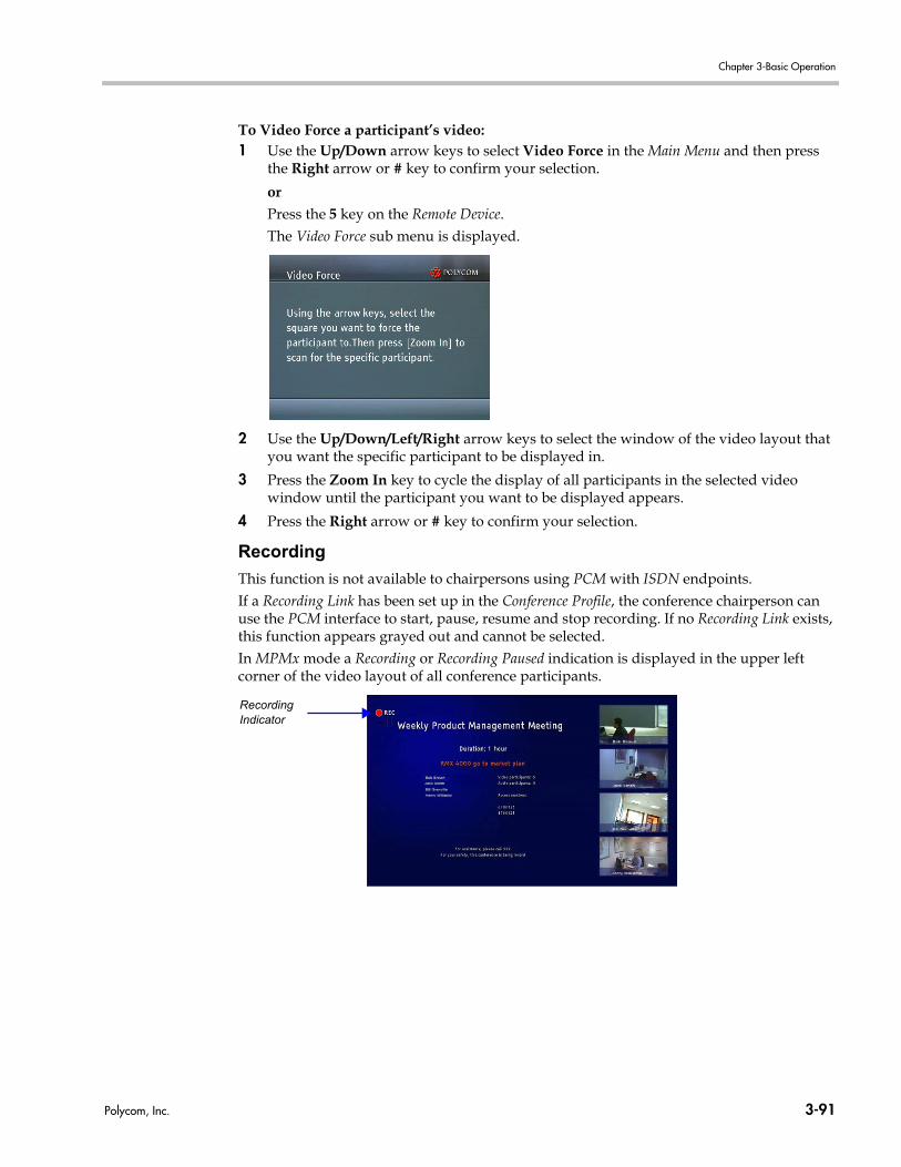
Chapter 3-Basic Operation
To Video Force a participant’s video:1 Use the Up/Down arrow keys to select Video Force in the Main Menu and then press
the Right arrow or # key to confirm your selection.
orPress the 5 key on the Remote Device.The Video Force sub menu is displayed.
2 Use the Up/Down/Left/Right arrow keys to select the window of the video layout that you want the specific participant to be displayed in.
3 Press the Zoom In key to cycle the display of all participants in the selected video window until the participant you want to be displayed appears.
4 Press the Right arrow or # key to confirm your selection.
Recording
This function is not available to chairpersons using PCM with ISDN endpoints.If a Recording Link has been set up in the Conference Profile, the conference chairperson can use the PCM interface to start, pause, resume and stop recording. If no Recording Link exists, this function appears grayed out and cannot be selected. In MPMx mode a Recording or Recording Paused indication is displayed in the upper left corner of the video layout of all conference participants.
RecordingIndicator
Polycom, Inc. 3-91
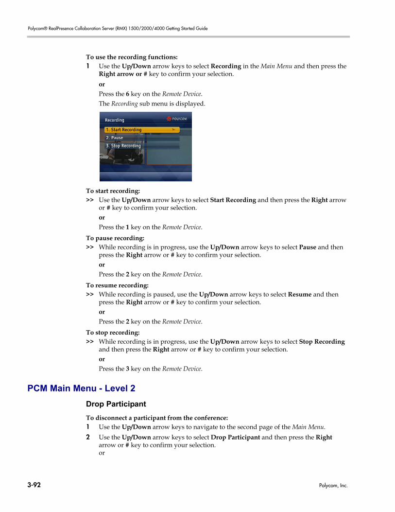
Polycom® RealPresence Collaboration Server (RMX) 1500/2000/4000 Getting Started Guide
To use the recording functions:1 Use the Up/Down arrow keys to select Recording in the Main Menu and then press the
Right arrow or # key to confirm your selection.
orPress the 6 key on the Remote Device.The Recording sub menu is displayed.
To start recording:>> Use the Up/Down arrow keys to select Start Recording and then press the Right arrow
or # key to confirm your selection.orPress the 1 key on the Remote Device.
To pause recording:>> While recording is in progress, use the Up/Down arrow keys to select Pause and then
press the Right arrow or # key to confirm your selection.orPress the 2 key on the Remote Device.
To resume recording:>> While recording is paused, use the Up/Down arrow keys to select Resume and then
press the Right arrow or # key to confirm your selection.orPress the 2 key on the Remote Device.
To stop recording:>> While recording is in progress, use the Up/Down arrow keys to select Stop Recording
and then press the Right arrow or # key to confirm your selection.orPress the 3 key on the Remote Device.
PCM Main Menu - Level 2
Drop Participant
To disconnect a participant from the conference:1 Use the Up/Down arrow keys to navigate to the second page of the Main Menu.
2 Use the Up/Down arrow keys to select Drop Participant and then press the Right arrow or # key to confirm your selection.or
3-92 Polycom, Inc.
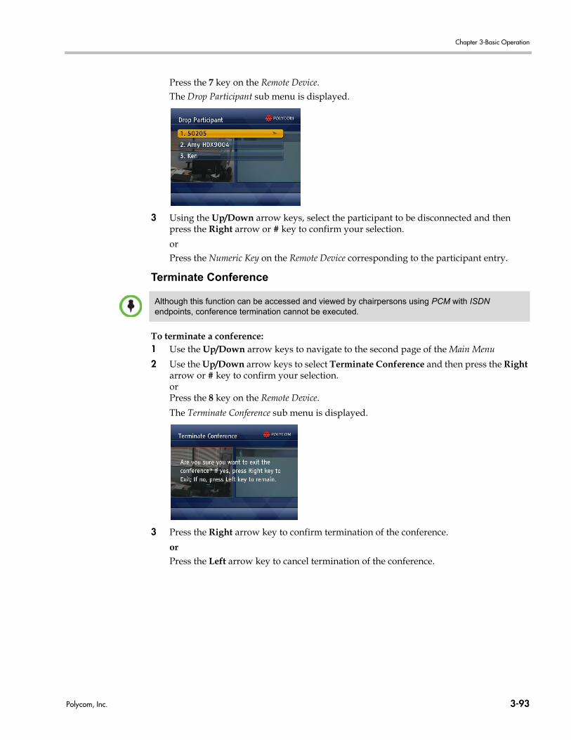
Chapter 3-Basic Operation
Press the 7 key on the Remote Device.The Drop Participant sub menu is displayed.
3 Using the Up/Down arrow keys, select the participant to be disconnected and then press the Right arrow or # key to confirm your selection.
orPress the Numeric Key on the Remote Device corresponding to the participant entry.
Terminate Conference
To terminate a conference:1 Use the Up/Down arrow keys to navigate to the second page of the Main Menu
2 Use the Up/Down arrow keys to select Terminate Conference and then press the Right arrow or # key to confirm your selection.orPress the 8 key on the Remote Device.
The Terminate Conference sub menu is displayed.
3 Press the Right arrow key to confirm termination of the conference.
orPress the Left arrow key to cancel termination of the conference.
Although this function can be accessed and viewed by chairpersons using PCM with ISDN endpoints, conference termination cannot be executed.
Polycom, Inc. 3-93

Polycom® RealPresence Collaboration Server (RMX) 1500/2000/4000 Getting Started Guide
3-94 Polycom, Inc.
Appendix A
GlossaryThis appendix lists the terms and abbreviations that are related to the RealPresence Collaboration Server (RMX) 1500/2000/4000, and are commonly used in the Collaboration Server documentation.
Abbreviation/Term
Explanation
AGC Auto Gain Control. A mechanism that regulates noise and audio volume by keeping the received signal of all participants balanced.
Bandwidth Defines the information carrying capacity of a channel. In analog systems, it is the difference between the highest frequency that a channel can carry and the lowest, measured in hertz. In digital systems, bandwidth is measured in bits per second. The larger a connection's bandwidth, the more data can be transmitted in a given amount of time, allowing for greater video resolution and more sites in a conference. For more information, see Line Rate.
Bonding Bandwidth ON Demand INterpolarity Group. A transmission protocol that aggregates two 64 Kbps B channels to function as one 128 Kbps channel. When using several BRI channels, Bonding means that only one D-channel serves all BRI channels, while the remaining D-channels are used for data transfer.See also: BRI.
Bps, Kbps Bits and kilobits per second; a unit of bandwidth, which is the amount of data that can flow during one second over a communications line (using a transmission medium).1 Kbps = 1000 Bps
BRI Basic Rate Interface. A type of ISDN connection for transiting data, consisting of 3 channels: two B-channels (each of 64 Kbps) and one D-channel (16 Kbps).
Carrier A telephone or other company that provides telecommunication transmission services.
CIF, 4CIF, QCIF Common Intermediate Format, an optional part of the ITU-T's H.261 and H.263 standards. CIF specifies 288 non-interlaced luminance lines, that contain 176 pixels. CIF can be sent at frame rates of 7.5, 10, 15, or 30 per second. When operating with CIF, the amount of data to transmit cannot exceed 256 K bits (where K equals 1024).The CIF video format has the capacity to transmit video images of 352x288 pixels at 36.45 Mbps and 30 frames per second. A 4CIF format has four times the capacity of CIF; QCIF has quarter the capacity of CIF.
Codec Coder-decoder. A device that converts voice and video into digital code, and vice versa. Refers to the endpoint video camera and video board that are used for video conferencing.
Polycom, Inc. A-1
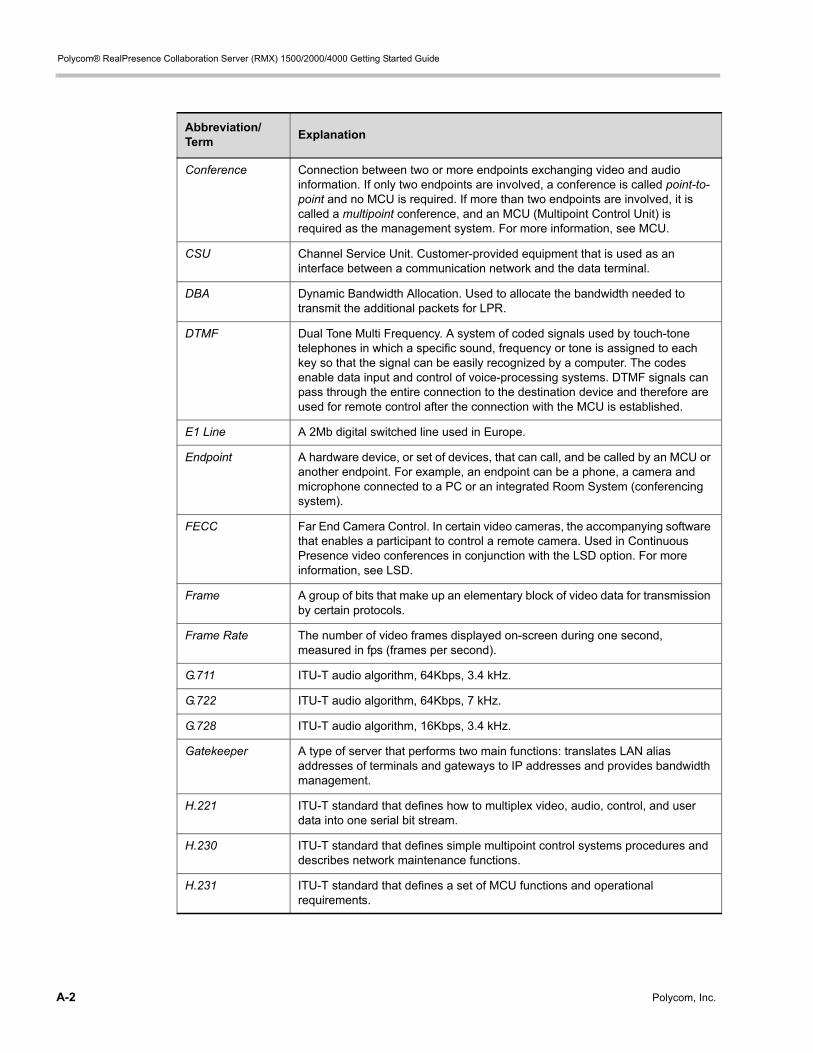
Polycom® RealPresence Collaboration Server (RMX) 1500/2000/4000 Getting Started Guide
Conference Connection between two or more endpoints exchanging video and audio information. If only two endpoints are involved, a conference is called point-to-point and no MCU is required. If more than two endpoints are involved, it is called a multipoint conference, and an MCU (Multipoint Control Unit) is required as the management system. For more information, see MCU.
CSU Channel Service Unit. Customer-provided equipment that is used as an interface between a communication network and the data terminal.
DBA Dynamic Bandwidth Allocation. Used to allocate the bandwidth needed to transmit the additional packets for LPR.
DTMF Dual Tone Multi Frequency. A system of coded signals used by touch-tone telephones in which a specific sound, frequency or tone is assigned to each key so that the signal can be easily recognized by a computer. The codes enable data input and control of voice-processing systems. DTMF signals can pass through the entire connection to the destination device and therefore are used for remote control after the connection with the MCU is established.
E1 Line A 2Mb digital switched line used in Europe.
Endpoint A hardware device, or set of devices, that can call, and be called by an MCU or another endpoint. For example, an endpoint can be a phone, a camera and microphone connected to a PC or an integrated Room System (conferencing system).
FECC Far End Camera Control. In certain video cameras, the accompanying software that enables a participant to control a remote camera. Used in Continuous Presence video conferences in conjunction with the LSD option. For more information, see LSD.
Frame A group of bits that make up an elementary block of video data for transmission by certain protocols.
Frame Rate The number of video frames displayed on-screen during one second, measured in fps (frames per second).
G.711 ITU-T audio algorithm, 64Kbps, 3.4 kHz.
G.722 ITU-T audio algorithm, 64Kbps, 7 kHz.
G.728 ITU-T audio algorithm, 16Kbps, 3.4 kHz.
Gatekeeper A type of server that performs two main functions: translates LAN alias addresses of terminals and gateways to IP addresses and provides bandwidth management.
H.221 ITU-T standard that defines how to multiplex video, audio, control, and user data into one serial bit stream.
H.230 ITU-T standard that defines simple multipoint control systems procedures and describes network maintenance functions.
H.231 ITU-T standard that defines a set of MCU functions and operational requirements.
Abbreviation/Term
Explanation
A-2 Polycom, Inc.
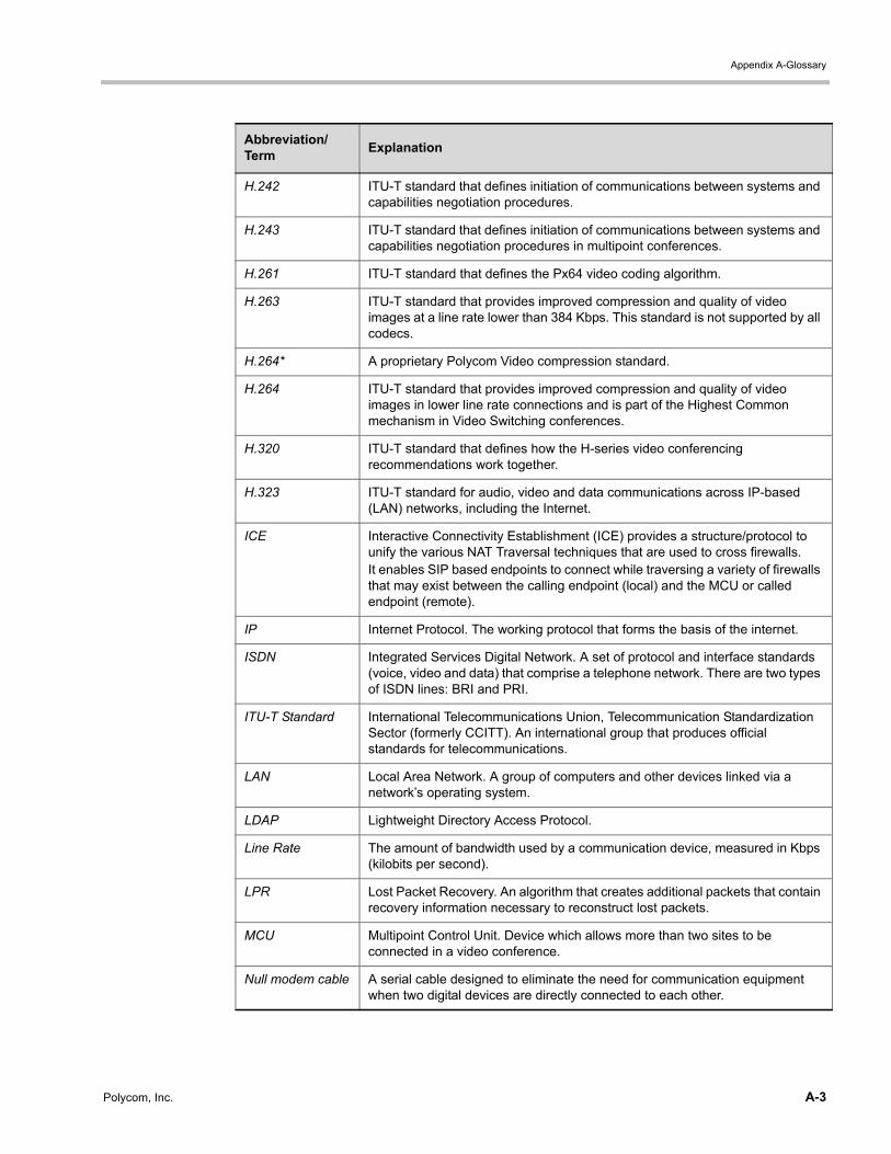
Appendix A-Glossary
H.242 ITU-T standard that defines initiation of communications between systems and capabilities negotiation procedures.
H.243 ITU-T standard that defines initiation of communications between systems and capabilities negotiation procedures in multipoint conferences.
H.261 ITU-T standard that defines the Px64 video coding algorithm.
H.263 ITU-T standard that provides improved compression and quality of video images at a line rate lower than 384 Kbps. This standard is not supported by all codecs.
H.264* A proprietary Polycom Video compression standard.
H.264 ITU-T standard that provides improved compression and quality of video images in lower line rate connections and is part of the Highest Common mechanism in Video Switching conferences.
H.320 ITU-T standard that defines how the H-series video conferencing recommendations work together.
H.323 ITU-T standard for audio, video and data communications across IP-based (LAN) networks, including the Internet.
ICE Interactive Connectivity Establishment (ICE) provides a structure/protocol to unify the various NAT Traversal techniques that are used to cross firewalls.It enables SIP based endpoints to connect while traversing a variety of firewalls that may exist between the calling endpoint (local) and the MCU or called endpoint (remote).
IP Internet Protocol. The working protocol that forms the basis of the internet.
ISDN Integrated Services Digital Network. A set of protocol and interface standards (voice, video and data) that comprise a telephone network. There are two types of ISDN lines: BRI and PRI.
ITU-T Standard International Telecommunications Union, Telecommunication Standardization Sector (formerly CCITT). An international group that produces official standards for telecommunications.
LAN Local Area Network. A group of computers and other devices linked via a network’s operating system.
LDAP Lightweight Directory Access Protocol.
Line Rate The amount of bandwidth used by a communication device, measured in Kbps (kilobits per second).
LPR Lost Packet Recovery. An algorithm that creates additional packets that contain recovery information necessary to reconstruct lost packets.
MCU Multipoint Control Unit. Device which allows more than two sites to be connected in a video conference.
Null modem cable A serial cable designed to eliminate the need for communication equipment when two digital devices are directly connected to each other.
Abbreviation/Term
Explanation
Polycom, Inc. A-3
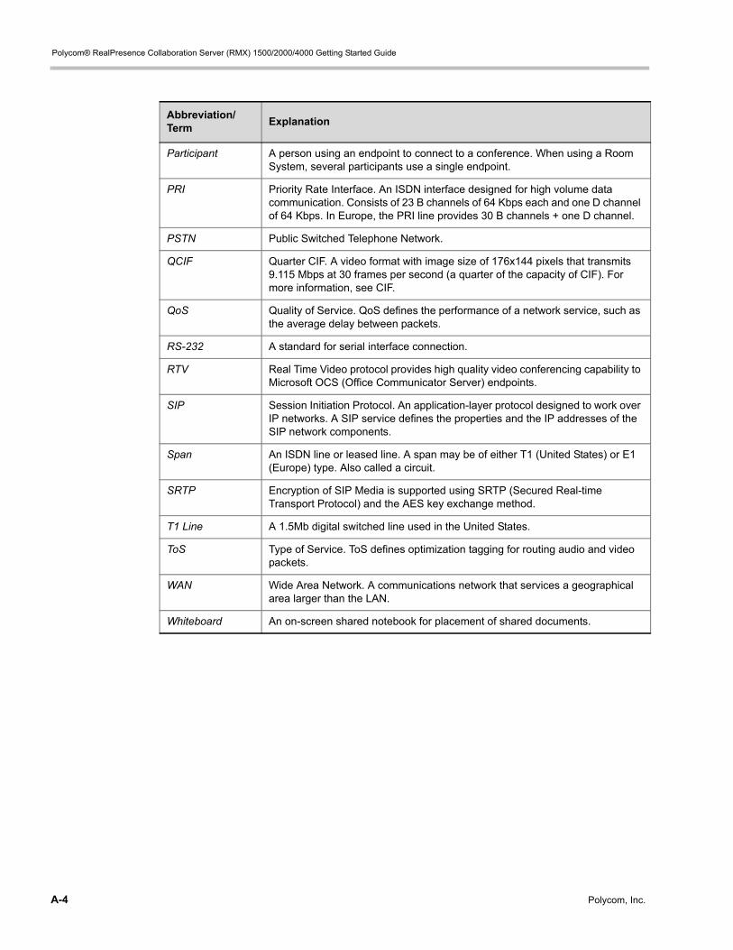
Polycom® RealPresence Collaboration Server (RMX) 1500/2000/4000 Getting Started Guide
Participant A person using an endpoint to connect to a conference. When using a Room System, several participants use a single endpoint.
PRI Priority Rate Interface. An ISDN interface designed for high volume data communication. Consists of 23 B channels of 64 Kbps each and one D channel of 64 Kbps. In Europe, the PRI line provides 30 B channels + one D channel.
PSTN Public Switched Telephone Network.
QCIF Quarter CIF. A video format with image size of 176x144 pixels that transmits 9.115 Mbps at 30 frames per second (a quarter of the capacity of CIF). For more information, see CIF.
QoS Quality of Service. QoS defines the performance of a network service, such as the average delay between packets.
RS-232 A standard for serial interface connection.
RTV Real Time Video protocol provides high quality video conferencing capability to Microsoft OCS (Office Communicator Server) endpoints.
SIP Session Initiation Protocol. An application-layer protocol designed to work over IP networks. A SIP service defines the properties and the IP addresses of the SIP network components.
Span An ISDN line or leased line. A span may be of either T1 (United States) or E1 (Europe) type. Also called a circuit.
SRTP Encryption of SIP Media is supported using SRTP (Secured Real-time Transport Protocol) and the AES key exchange method.
T1 Line A 1.5Mb digital switched line used in the United States.
ToS Type of Service. ToS defines optimization tagging for routing audio and video packets.
WAN Wide Area Network. A communications network that services a geographical area larger than the LAN.
Whiteboard An on-screen shared notebook for placement of shared documents.
Abbreviation/Term
Explanation
A-4 Polycom, Inc.
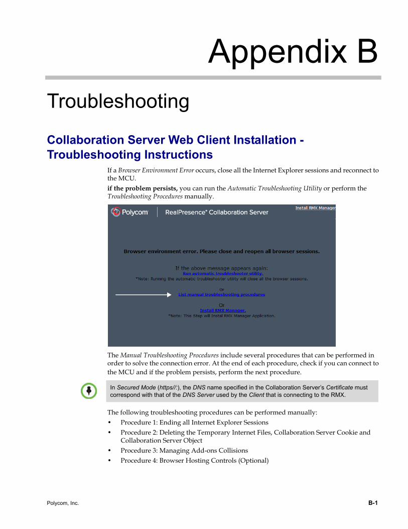
Appendix B
TroubleshootingCollaboration Server Web Client Installation - Troubleshooting Instructions
If a Browser Environment Error occurs, close all the Internet Explorer sessions and reconnect to the MCU.if the problem persists, you can run the Automatic Troubleshooting Utility or perform the Troubleshooting Procedures manually.
The Manual Troubleshooting Procedures include several procedures that can be performed in order to solve the connection error. At the end of each procedure, check if you can connect to the MCU and if the problem persists, perform the next procedure.
The following troubleshooting procedures can be performed manually: • Procedure 1: Ending all Internet Explorer Sessions• Procedure 2: Deleting the Temporary Internet Files, Collaboration Server Cookie and
Collaboration Server Object• Procedure 3: Managing Add-ons Collisions• Procedure 4: Browser Hosting Controls (Optional)
In Secured Mode (https//:), the DNS name specified in the Collaboration Server’s Certificate must correspond with that of the DNS Server used by the Client that is connecting to the RMX.
Polycom, Inc. B-1
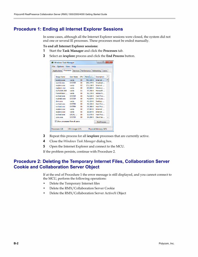
Polycom® RealPresence Collaboration Server (RMX) 1500/2000/4000 Getting Started Guide
Procedure 1: Ending all Internet Explorer Sessions
In some cases, although all the Internet Explorer sessions were closed, the system did not end one or several IE processes. These processes must be ended manually.
To end all Internet Explorer sessions:1 Start the Task Manager and click the Processes tab.
2 Select an iexplore process and click the End Process button.
3 Repeat this process for all iexplore processes that are currently active.
4 Close the Windows Task Manager dialog box.
5 Open the Internet Explorer and connect to the MCU.
If the problem persists, continue with Procedure 2.
Procedure 2: Deleting the Temporary Internet Files, Collaboration Server Cookie and Collaboration Server Object
If at the end of Procedure 1 the error message is still displayed, and you cannot connect to the MCU, perform the following operations:• Delete the Temporary Internet files• Delete the RMX/Collaboration Server Cookie• Delete the RMX/Collaboration Server ActiveX Object
B-2 Polycom, Inc.
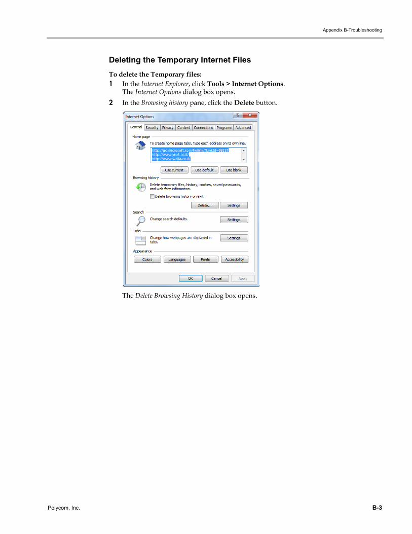
Appendix B-Troubleshooting
Deleting the Temporary Internet Files
To delete the Temporary files:1 In the Internet Explorer, click Tools > Internet Options.
The Internet Options dialog box opens.
2 In the Browsing history pane, click the Delete button.
The Delete Browsing History dialog box opens.
Polycom, Inc. B-3
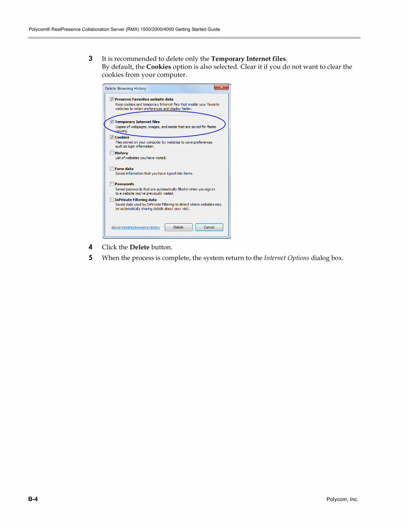
Polycom® RealPresence Collaboration Server (RMX) 1500/2000/4000 Getting Started Guide
3 It is recommended to delete only the Temporary Internet files. By default, the Cookies option is also selected. Clear it if you do not want to clear the cookies from your computer.
4 Click the Delete button.
5 When the process is complete, the system return to the Internet Options dialog box.
B-4 Polycom, Inc.
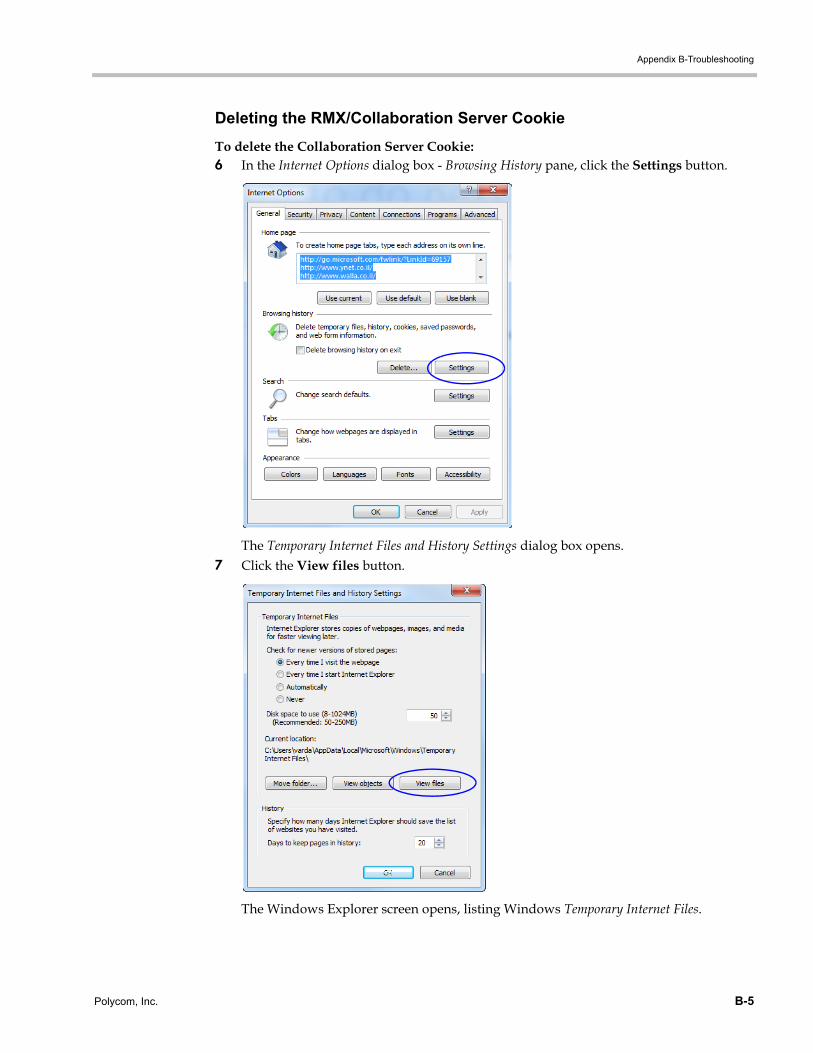
Appendix B-Troubleshooting
Deleting the RMX/Collaboration Server Cookie
To delete the Collaboration Server Cookie:6 In the Internet Options dialog box - Browsing History pane, click the Settings button.
The Temporary Internet Files and History Settings dialog box opens.7 Click the View files button.
The Windows Explorer screen opens, listing Windows Temporary Internet Files.
Polycom, Inc. B-5
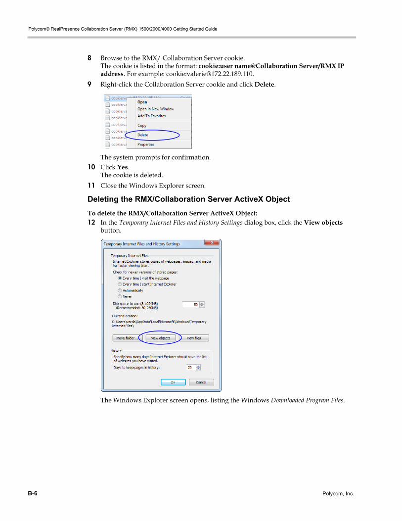
Polycom® RealPresence Collaboration Server (RMX) 1500/2000/4000 Getting Started Guide
8 Browse to the RMX/ Collaboration Server cookie. The cookie is listed in the format: cookie:user name@Collaboration Server/RMX IP address. For example: cookie:[email protected].
9 Right-click the Collaboration Server cookie and click Delete.
The system prompts for confirmation.10 Click Yes.
The cookie is deleted.
11 Close the Windows Explorer screen.
Deleting the RMX/Collaboration Server ActiveX Object
To delete the RMX/Collaboration Server ActiveX Object:12 In the Temporary Internet Files and History Settings dialog box, click the View objects
button.
The Windows Explorer screen opens, listing the Windows Downloaded Program Files.
B-6 Polycom, Inc.
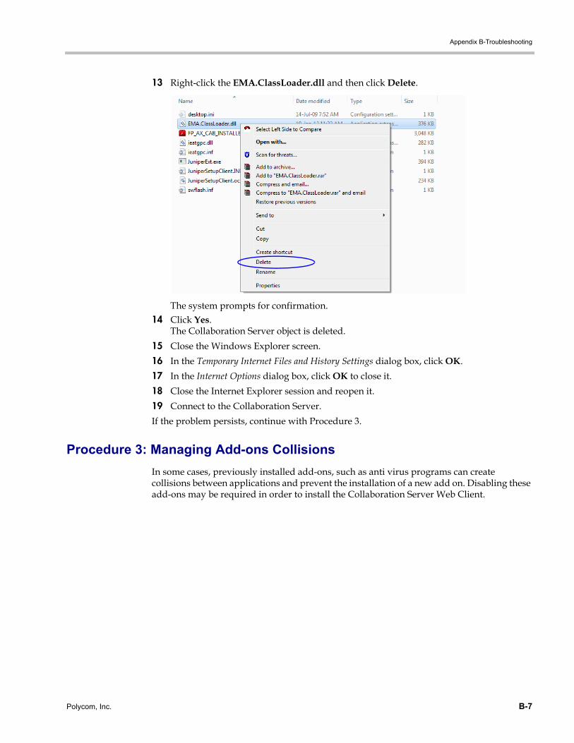
Appendix B-Troubleshooting
13 Right-click the EMA.ClassLoader.dll and then click Delete.
The system prompts for confirmation.14 Click Yes.
The Collaboration Server object is deleted.
15 Close the Windows Explorer screen.
16 In the Temporary Internet Files and History Settings dialog box, click OK.
17 In the Internet Options dialog box, click OK to close it.
18 Close the Internet Explorer session and reopen it.
19 Connect to the Collaboration Server.
If the problem persists, continue with Procedure 3.
Procedure 3: Managing Add-ons Collisions
In some cases, previously installed add-ons, such as anti virus programs can create collisions between applications and prevent the installation of a new add on. Disabling these add-ons may be required in order to install the Collaboration Server Web Client.
Polycom, Inc. B-7
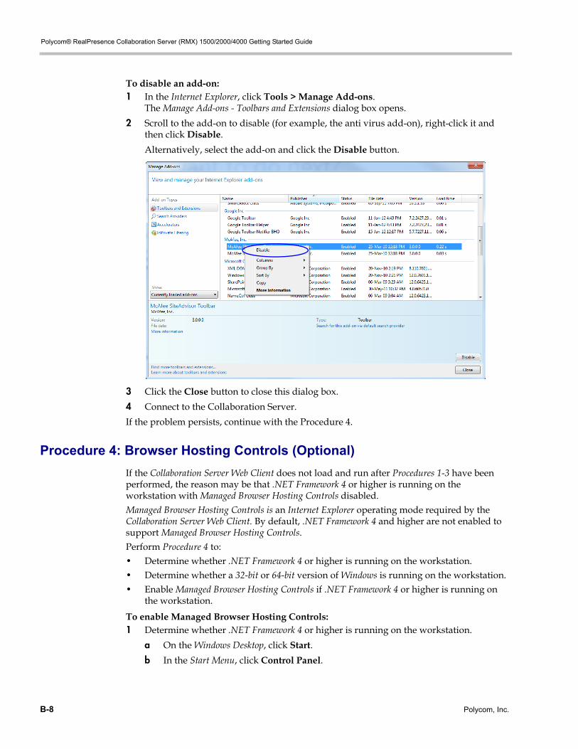
Polycom® RealPresence Collaboration Server (RMX) 1500/2000/4000 Getting Started Guide
To disable an add-on:1 In the Internet Explorer, click Tools > Manage Add-ons.
The Manage Add-ons - Toolbars and Extensions dialog box opens.
2 Scroll to the add-on to disable (for example, the anti virus add-on), right-click it and then click Disable.
Alternatively, select the add-on and click the Disable button.
3 Click the Close button to close this dialog box.
4 Connect to the Collaboration Server.
If the problem persists, continue with the Procedure 4.
Procedure 4: Browser Hosting Controls (Optional)
If the Collaboration Server Web Client does not load and run after Procedures 1-3 have been performed, the reason may be that .NET Framework 4 or higher is running on the workstation with Managed Browser Hosting Controls disabled.Managed Browser Hosting Controls is an Internet Explorer operating mode required by the Collaboration Server Web Client. By default, .NET Framework 4 and higher are not enabled to support Managed Browser Hosting Controls.Perform Procedure 4 to:• Determine whether .NET Framework 4 or higher is running on the workstation.• Determine whether a 32-bit or 64-bit version of Windows is running on the workstation.• Enable Managed Browser Hosting Controls if .NET Framework 4 or higher is running on
the workstation.
To enable Managed Browser Hosting Controls:1 Determine whether .NET Framework 4 or higher is running on the workstation.
a On the Windows Desktop, click Start.
b In the Start Menu, click Control Panel.
B-8 Polycom, Inc.
Appendix B-Troubleshooting
c In the Control Panel, click Programs and Features.
d Inspect the Programs and Features list for the version of Microsoft .NET Framework Client Profile that is installed.
2 Determine whether a 32-bit or 64-bit version of Windows is running on the workstation:
a On the Windows Desktop, click Start.
b In the Start Menu, click Computer.
c In the Computer Menu, System properties and inspect the value of the System type field in the System section
3 Enable Managed Browser Hosting Controls if .NET Framework 4 or higher is running on the workstation.
a Open the Registry.
b Navigate to the Subkey:
• 32-bit System: HKEY_LOCAL_MACHINE\SOFTWARE\MICROSOFT\.NETFramework
• 64-bit System: HKEY_LOCAL_MACHINE\SOFTWARE\Wow6432Node\Microsoft\.NETFramework
c Add the Dword Value: EnableIEHosting
d Set value of EnableIEHosting to 1.
e Close the Registry.
f Close and re-open Internet Explorer.
Polycom, Inc. B-9

Polycom® RealPresence Collaboration Server (RMX) 1500/2000/4000 Getting Started Guide
B-10 Polycom, Inc.