Embed Size (px)
Citation preview

www.wackergroup.com
Internal Vibrator
M 1000M 2000M 3000
OPERATOR’S MANUAL
0154561en 001
0403
0 1 5 4 5 6 1 E N


Foreword
wc_tx000001gb.fm
Engine exhaust, some of its constituents, and certain vehiclecomponents contain or emit chemicals known to the State of Californiato cause cancer and birth defects or other reproductive harm.
1. Foreword
This manual provides information and procedures to safely operateand maintain this Wacker model. For your own safety and protectionfrom injury, carefully read, understand and observe the safetyinstructions described in this manual.
Keep this manual or a copy of it with the machine. If you lose thismanual or need an additional copy, please contact WackerCorporation. This machine is built with user safety in mind; however,it can present hazards if improperly operated and serviced. Followoperating instructions carefully! If you have questions about operatingor servicing this equipment, please contact Wacker Corporation.
The information contained in this manual was based on machines inproduction at the time of publication. Wacker Corporation reserves theright to change any portion of this information without notice.
All rights, especially copying and distribution rights are reserved.
Copyright 2002 by Wacker Corporation.
No part of this publication may be reproduced in any form or by anymeans, electronic or mechanical, including photocopying, withoutexpress written permission from Wacker Corporation.
Any type of reproduction or distribution not authorized by WackerCorporation represents an infringement of valid copyrights and will beprosecuted. We expressly reserve the right to make technicalmodifications, even without due notice, which aim at improving ourmachines or their safety standards.
WARNING

HMS
ii
MADE IN
USA
87
577
hplbs kWkg
Month / YeardB(A)
Item Number Rev. Serial Number
MENOMONEE FALLS, WI USA 53051Model
Serial NumberMaschinen-Nummer
Número de SerieNuméro de Série
My machine’s numbers are / Die Nummern meines Gerätes sind /Los números de mi máquina son / Les numéros de ma machine sont :
RevisionVersion
Nivel de revisiónNiveau de revision
Item Number Artikel-Nummer
Número de referencia Numéro de référence
Model numberTyp
ModeloModèle
M1000M1000M1000M1000M1000
00050410005041000504100050410005041 101101101101101 50101015010101501010150101015010101
Nameplate / Typenschild / Placa de Identificación / Plaque signalétique
A nameplate listing the Model Number, Item Number, Revision, and Serial Number is attached to each unit. Pleaserecord the information found on this plate so it will be available should the nameplate become lost or damaged. Whenordering parts or requesting service information, you will always be asked to specify the model, item number,revision number, and serial number of the unit.
Ein Typenschild mit Typ, Artikelnummer, Version und Maschinen-Nummer ist an jedem Gerät angebracht. Die Datenvon diesem Schild bitte notieren, damit sie auch bei Verlust oder Beschädigung des Schildes noch vorhanden sind.Der Typ, die Artikel-Nummer, die Versions-Nummer und die Maschinen-Nummer sind bei der Ersatzteilbestellungoder Nachfragen bezüglich Service-Informationen stets erforderlich.
Una placa de identificación con el modelo, número de referencia, nivel de revisión y número de serie ha sido añadidaen cada máquina. Favor de anotar los datos en la placa en caso de que la placa de identificación sea destruida operdida. En todos los pedidos para repuestos necesita siempre el modelo, el número de referencia, el nivel derevisión y el número de serie de la máquina en cuestión.
Une plaque signalétique mentionnant le modèle, le numéro de référence, le niveau de revision et le numéro de sérieest fixée sur chaque machine. Veuillez noter les informations relevées sur cette plaque de façon à ce qu’elles soienttoujours disponibles si la plaque signalétique venait à être perdue ou endommagée. Lorsque vous commandez despièces détachées ou vous sollicitez des informations auprès-vente, on vous demandera toujours de préciserle modèle, le numéro de référence, le niveau de revision et le numéro de série de la machine.
1007SD48
1
1A-1
HMSOperating Information 1A
Contents
1.1 Safety Information ................................................................................ 1A-21.2 Safety ................................................................................................... 1A-31.3 Technical Data ..................................................................................... 1A-41.4 Safety & Informational Labels .............................................................. 1A-51.5 Label Locations .................................................................................... 1A-51.6 Application ........................................................................................... 1A-61.7 Recommended HMS Combinations ..................................................... 1A-61.8 Extension Cords ................................................................................... 1A-71.9 Connecting Motor to Power Supply ...................................................... 1A-71.10 Assembling Head, Motor and Shaft ...................................................... 1A-81.11 Operation ............................................................................................. 1A-81.12 Periodic Maintenance ........................................................................... 1A-91.13 Motor Brushes ...................................................................................... 1A-91.14 Motor Housing ...................................................................................... 1A-91.15 Lubricating Shaft ................................................................................ 1A-101.16 Lubricating Head ................................................................................ 1A-101.17 Checking Head for Wear .................................................................... 1A-111.18 Troubleshooting ................................................................................. 1A-111.19 Wiring Schematics ............................................................................. 1A-12

1A OPERATION HMS
1A-2
1.1 Safety Information
This manual contains DANGER, WARNING, CAUTION, and NOTE callouts which must be followed to reduce thepossibility of personal injury, damage to the equipment, or improper service.
CAUTION: Used without the safety alert symbol,CAUTION indicates a potentially hazardous situationwhich, if not avoided, may result in property damage.
Note: Contains additional information important to a procedure.
This is the safety alert symbol. It is used to alert you topotential personal injury hazards. Obey all safety messagesthat follow this symbol to avoid possible injury or death.
DANGER indicates an imminently hazardoussituation which, if not avoided, will result in
death or serious injury.
CAUTION indicates a potentially hazardoussituation which, if not avoided, may result in
minor or moderate injury.
WARNING indicates a potentially hazardoussituation which, if not avoided, could result in
death or serious injury.
DANGER
WARNING
CAUTION

HMS OPERATION 1A
1A-3
Familiarity and proper training are required for the safe operation of this equipment! Equipment operated or servicedimproperly or by untrained personnel can be dangerous! Read all operating instructions and the safety notes below.Familiarize yourself with the proper use of this equipment before operating it.
WARNING
Keep work area clean and free of clutter.
Keep work area well lit.
Do not allow children or people other than the opera-tor to handle power cables, extension cords or theequipment.
Do not allow non-essential personnel or visitors in thework area.
Never operate motor in areas exposed to flammableor explosive liquids or gases! The motor brushesspark during operating and could ignite fumes.
Don't overreach! Keep proper footing and balance atall times. Make sure any supporting structures arestrong enough and stable enough to support yourweight and the weight of any equipment on it.
Keep hands, feet, hair and loose clothing away frommoving parts. They can be caught in moving parts.
Wear protective clothing when operating equipment.Goggles or safety glasses will protect against eyedamage caused by flying debris.
Never carry motor by cord or pull on it to disconnectit from receptacle. Keep cord away from heat, oil andsharp edges.
Keep handle, and other areas where motor and shaftare gripped, dry, clean and free from oil and grease.
Avoid unintentional starting! Don't carry motor aroundjobsite while it is connected to power source. Don'tcarry motor with finger on switch.
Stay alert! Watch what you are doing. Use commonsense. Do not operate tool when you are tired.
Do not operate equipment if switch does not operateproperly.
Replace worn or damaged parts with replacementparts designed and recommended for use byWACKER Corporation.
Don't overload motor. An overloaded motor will over-heat. Use only recommended head/motor/shaft com-binations. See Table 1.
Never allow untrained personnel to operate or servicethe equipment.
Never attach shaft to motor while it is running.
Always check the power supply before running motor.Using the wrong voltage supply will damage motor.
Always make sure motor switch is OFF before plug-ging motor to power supply.
Any servicing, other than that covered in this instruc-tion manual, should be performed by an authorizedWACKER Service Representative.
1.2 Safety
When using electric tools, basic safety precautions should always be followed to reduce the risk of fire, electric shock,and personal injury! The guidelines following will help the user maintain operator safety.
When motor is used outdoors, use only extensioncords intended for and marked for outdoor use.
Always keep power cord away from heat, oil andsharp edges which can damage it.
Make certain motor is in good working order andproperly grounded before starting.
Never operate motor with damaged or worn electricalcords! When using an extension cord be sure to useone heavy enough to carry the current load. See Table2 for correct cable size to use.
Prevent body contact with grounded surfaces, such aspipes, metal railings, radiators and metal ductwork.
DANGER
1A OPERATION HMS
1A-4
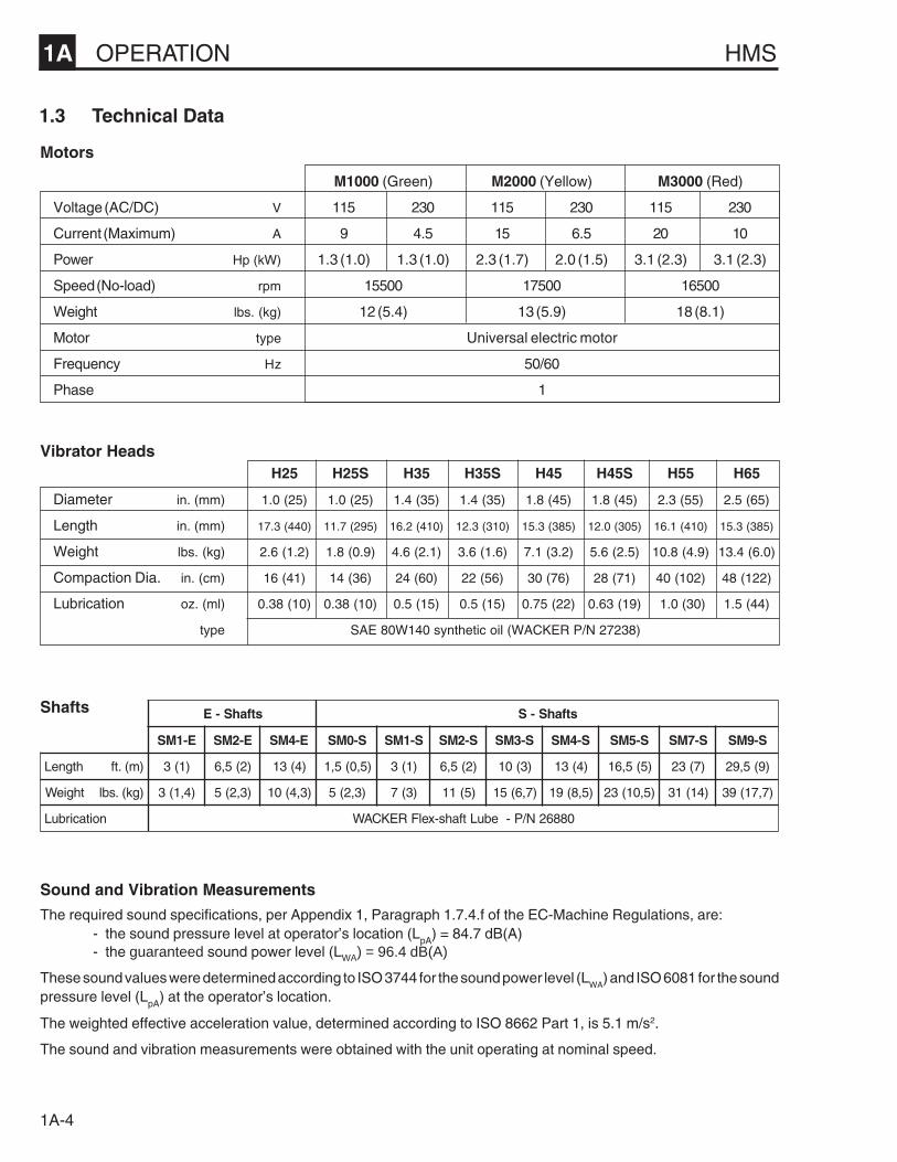
M1000 (Green) M2000 (Yellow) M3000 (Red)
Voltage (AC/DC) V 115 230 115 230 115 230
Current (Maximum) A 9 4.5 15 6.5 20 10
Power Hp (kW) 1.3 (1.0) 1.3 (1.0) 2.3 (1.7) 2.0 (1.5) 3.1 (2.3) 3.1 (2.3)
Speed (No-load) rpm 15500 17500 16500
Weight lbs. (kg) 12 (5.4) 13 (5.9) 18 (8.1)
Motor type Universal electric motor
Frequency Hz 50/60
Phase 1
1.3 Technical Data
H25 H25S H35 H35S H45 H45S H55 H65
Diameter in. (mm) 1.0 (25) 1.0 (25) 1.4 (35) 1.4 (35) 1.8 (45) 1.8 (45) 2.3 (55) 2.5 (65)
Length in. (mm) 17.3 (440) 11.7 (295) 16.2 (410) 12.3 (310) 15.3 (385) 12.0 (305) 16.1 (410) 15.3 (385)
Weight lbs. (kg) 2.6 (1.2) 1.8 (0.9) 4.6 (2.1) 3.6 (1.6) 7.1 (3.2) 5.6 (2.5) 10.8 (4.9) 13.4 (6.0)
Compaction Dia. in. (cm) 16 (41) 14 (36) 24 (60) 22 (56) 30 (76) 28 (71) 40 (102) 48 (122)
Lubrication oz. (ml) 0.38 (10) 0.38 (10) 0.5 (15) 0.5 (15) 0.75 (22) 0.63 (19) 1.0 (30) 1.5 (44)
type SAE 80W140 synthetic oil (WACKER P/N 27238)
Sound and Vibration Measurements
The required sound specifications, per Appendix 1, Paragraph 1.7.4.f of the EC-Machine Regulations, are:- the sound pressure level at operator’s location (LpA) = 84.7 dB(A)- the guaranteed sound power level (LWA) = 96.4 dB(A)
These sound values were determined according to ISO 3744 for the sound power level (LWA
) and ISO 6081 for the soundpressure level (LpA) at the operator’s location.
The weighted effective acceleration value, determined according to ISO 8662 Part 1, is 5.1 m/s2.
The sound and vibration measurements were obtained with the unit operating at nominal speed.
Vibrator Heads
Motors
Shafts stfahS-E stfahS-S
E-1MS E-2MS E-4MS S-0MS S-1MS S-2MS S-3MS S-4MS S-5MS S-7MS S-9MS
htgneL )m(.tf )1(3 )2(5,6 )4(31 )5,0(5,1 )1(3 )2(5,6 )3(01 )4(31 )5(5,61 )7(32 )9(5,92
thgieW )gk(.sbl )4,1(3 )3,2(5 )3,4(01 )3,2(5 )3(7 )5(11 )7,6(51 )5,8(91 )5,01(32 )41(13 )7,71(93
noitacirbuL 08862N/P-ebuLtfahs-xelFREKCAW

HMS OPERATION 1A
1A-5
FOR SAFE OPERATION READOPERATOR’S MANUAL.
POUR UNE OPERATION SÛRELISEZ LA NOTICE D’EMPLOI.
SICHERHEITSANLEITUNGEN INBETRIEBSVORSCHRIFT LESEN.
PARA OPERACION SEGURA LEA MANUAL DE OPERACION.
CAUTION
VORSICHT
PRECAUTION
PRECAUCION
1039SD1978071-16
1.5 Label Locations
1.4 Safety & Informational Labels
This WACKER machine uses international pictorial labels where needed. These labels are described below:
Label Meaning
Read operator’s manual for machine information.
Wear eye, ear, and head protection whenoperating machine.
1A OPERATION HMS
1A-6
1.6 Application
The HMS series of internal vibrators can be used over awide range of applications for the consolidation of con-crete.
WACKER internal vibrators are typically used for on-sitevibration of concrete for foundations, walls, columns,slab work, etc. Additional in-plant applications includevibration of concrete during the production of pipes,slabs, beams, double T columns, walls, etc.
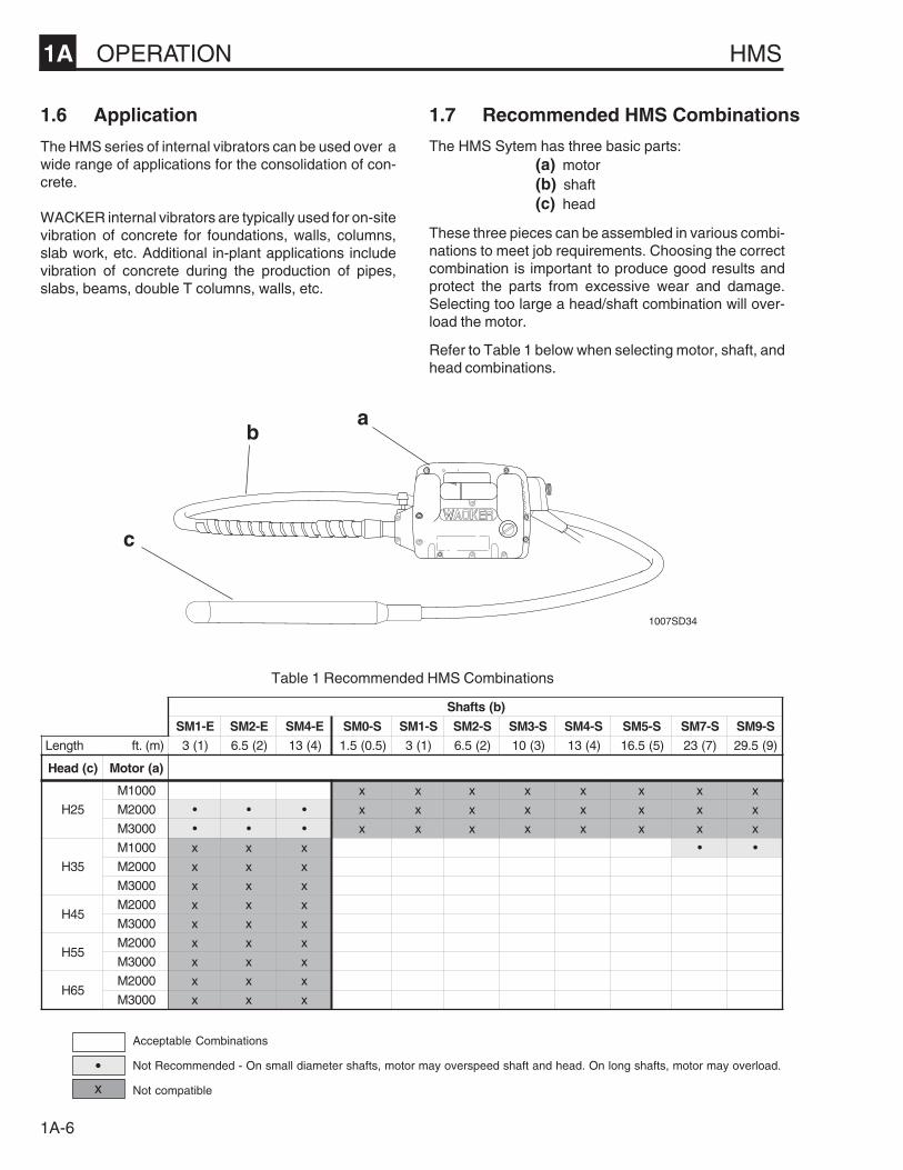
Acceptable Combinations
Not Recommended - On small diameter shafts, motor may overspeed shaft and head. On long shafts, motor may overload.
Not compatible
ab
c
1007SD34
1.7 Recommended HMS Combinations
)b(stfahS
E-1MS E-2MS E-4MS S-0MS S-1MS S-2MS S-3MS S-4MS S-5MS S-7MS S-9MShtgneL )m(.tf )1(3 )2(5.6 )4(31 )5.0(5.1 )1(3 )2(5.6 )3(01 )4(31 )5(5.61 )7(32 )9(5.92
)c(daeH )a(rotoM
52H
0001M x x x x x x x x
0002M • • • x x x x x x x x
0003M • • • x x x x x x x x
53H
0001M x x x • •
0002M x x x
0003M x x x
54H0002M x x x
0003M x x x
55H0002M x x x
0003M x x x
56H0002M x x x
0003M x x x
The HMS Sytem has three basic parts:(a) motor(b) shaft(c) head
These three pieces can be assembled in various combi-nations to meet job requirements. Choosing the correctcombination is important to produce good results andprotect the parts from excessive wear and damage.Selecting too large a head/shaft combination will over-load the motor.
Refer to Table 1 below when selecting motor, shaft, andhead combinations.
Table 1 Recommended HMS Combinations
•
x

HMS OPERATION 1A
1A-7
1.8 Extension Cords
Extension cords are often required on jobsites to connectthe motor. When choosing an extension cord make sureit has adequate wire size for safety. An undersized cordwill cause a drop in line voltage resulting in a loss of powerand overheating. Refer to Table 2 when selecting exten-sion cords. It shows the correct wire size to use depend-ing on cord length. If in doubt, use the next heavier cordsize.
On motors being used outdoors, use extension cordsrated for outdoor use.
WARNING
MAXIMUM CORD LENGTH - ft. (m)
25' 50' 100' 150' 175' 200'(7.5m) (15 m) (30 m) (45 m) (55 m) (60 m)
M1000 16 (1.5) 16 (1.5) 14 (2.5) 14 (2.5) 12 (4) 12 (4)
M2000 16 (1.5) 16 (1.5) 14 (2.5) 12 (4) 10 (6) 10 (6)
M3000 16 (1.5) 14 (2.5) 12 (4) 10 (6) 8 (10) 8 (10)
M1000 16 (1.5) 16 (1.5) 16 (1.5) 16 (1.5) 14 (2.5) 14 (2.5)
M2000 16 (1.5) 16 (1.5) 16 (1.5) 14 (2.5) 14 (2.5) 14 (2.5)
M3000 16 (1.5) 16 (1.5) 14 (2.5) 14 (2.5) 12 (4) 12 (4)
115V
Table 2Minimum wire size for extension cords -
AWG (mm2)
230V
To reduce the risk of electric shock, motors equippedwith 3-wire grounded plugs must be properly ground-ed. On these motors use only 3-wire grounded plugs,receptacles, and extension cords.
1.9 Connecting Motor to Power Supply
WARNINGImproper use of extension cords can cause over-heating or create serious fire or shock hazards.Never use worn or damaged cords!
Note: Not all countries require the use of a three-wiregrounded plug for this piece of equipment. In thesecountries, motors are equipped with a two-wire plugwhich can be plugged into a standard electrical outlet.
d e1007SD13
1. Check that switch on motor is off before connectingmotor to power source.
2. Make sure power supply matches voltage require-ments listed on motor label. Running a motor at a lowvoltage will cause it to run slow. This will reduceperfomance and may cause motor to overheat.
3. On motors equipped with a three wire grounded pluguse three-wire grounded receptacles (d) when con-necting the motor. If a 3-wire grounded receptacle isnot available, then a grounded adapter must be in-stalled as shown in illustration (e) to ensure a properground connection.
1A OPERATION HMS
1A-8
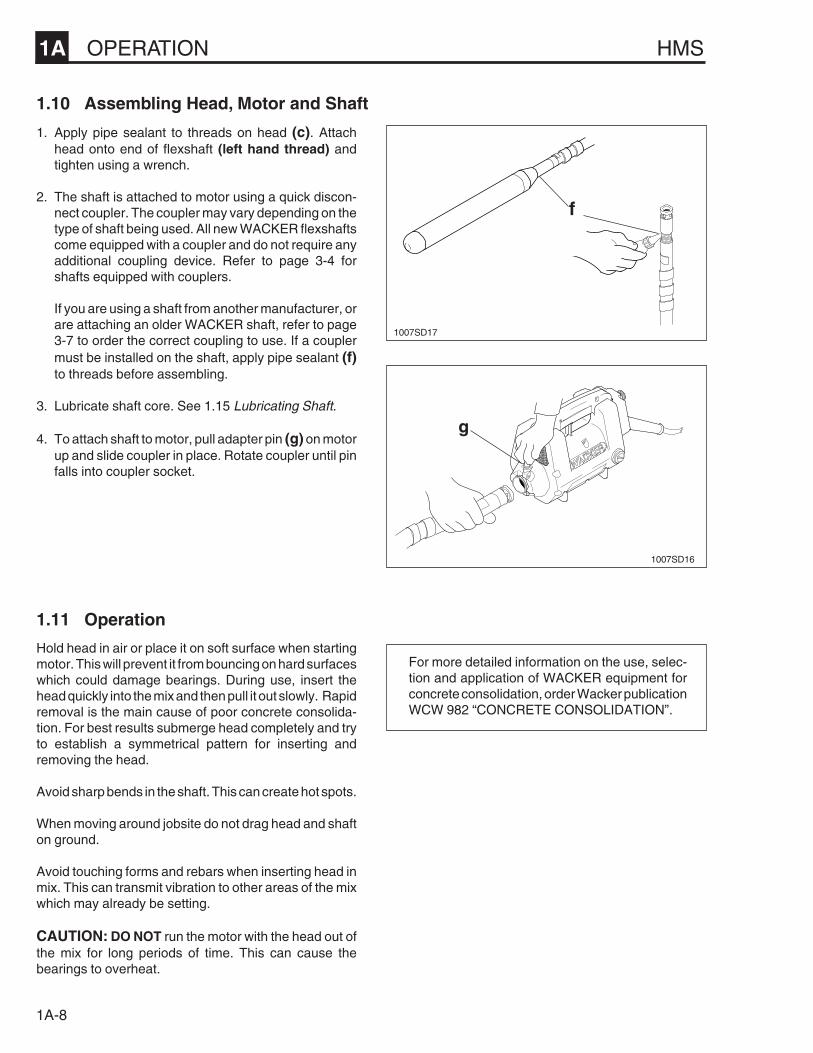
1.10 Assembling Head, Motor and Shaft
f
g
1007SD17
1007SD16
1.11 Operation
Hold head in air or place it on soft surface when startingmotor. This will prevent it from bouncing on hard surfaceswhich could damage bearings. During use, insert thehead quickly into the mix and then pull it out slowly. Rapidremoval is the main cause of poor concrete consolida-tion. For best results submerge head completely and tryto establish a symmetrical pattern for inserting andremoving the head.
Avoid sharp bends in the shaft. This can create hot spots.
When moving around jobsite do not drag head and shafton ground.
Avoid touching forms and rebars when inserting head inmix. This can transmit vibration to other areas of the mixwhich may already be setting.
CAUTION: DO NOT run the motor with the head out ofthe mix for long periods of time. This can cause thebearings to overheat.
For more detailed information on the use, selec-tion and application of WACKER equipment forconcrete consolidation, order Wacker publicationWCW 982 “CONCRETE CONSOLIDATION”.
1. Apply pipe sealant to threads on head (c). Attachhead onto end of flexshaft (left hand thread) andtighten using a wrench.
2. The shaft is attached to motor using a quick discon-nect coupler. The coupler may vary depending on thetype of shaft being used. All new WACKER flexshaftscome equipped with a coupler and do not require anyadditional coupling device. Refer to page 3-4 forshafts equipped with couplers.
If you are using a shaft from another manufacturer, orare attaching an older WACKER shaft, refer to page3-7 to order the correct coupling to use. If a couplermust be installed on the shaft, apply pipe sealant (f)to threads before assembling.
3. Lubricate shaft core. See 1.15 Lubricating Shaft.
4. To attach shaft to motor, pull adapter pin (g) on motorup and slide coupler in place. Rotate coupler until pinfalls into coupler socket.
HMS OPERATION 1A
1A-9
1.12 Periodic Maintenance
Before Operating Inspect air filter and vent holes. Clean or replace dirty or clogged filters.
Inspect electrical cords for wear or damage. Do not use damaged cords.
Every 50 hours Inspect brushes in motor.
Every 100 hours Clean and lubricate core in shaft.
Every 300 hours Change oil in head.
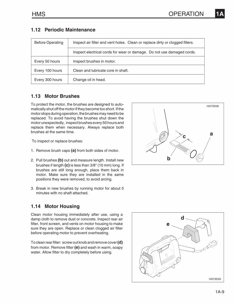
1.14 Motor Housing
Clean motor housing immediately after use, using adamp cloth to remove dust or concrete. Inspect rear airfilter, front screen, and vents on motor housing to makesure they are open. Replace or clean clogged air filterbefore operating motor to prevent overheating.
To clean rear filter: screw out knob and remove cover (d)from motor. Remove filter (e) and wash in warm, soapywater. Allow filter to dry completely before using.
1.13 Motor Brushes
To protect the motor, the brushes are designed to auto-matically shut off the motor if they become too short. If themotor stops during operation, the brushes may need to bereplaced. To avoid having the brushes shut down themotor unexpectedly, inspect brushes every 50 hours andreplace them when necessary. Always replace bothbrushes at the same time.
To inspect or replace brushes:
1. Remove brush caps (a) from both sides of motor.
2. Pull brushes (b) out and measure length. Install newbrushes if length (c) is less than 3/8" (10 mm) long. Ifbrushes are still long enough, place them back inmotor. Make sure they are installed in the samepositions they were removed, to avoid arcing.
3. Break in new brushes by running motor for about 5minutes with no shaft attached.
c a
b
1007SD06
de
1007SD05
1A OPERATION HMS
1A-10
f
g
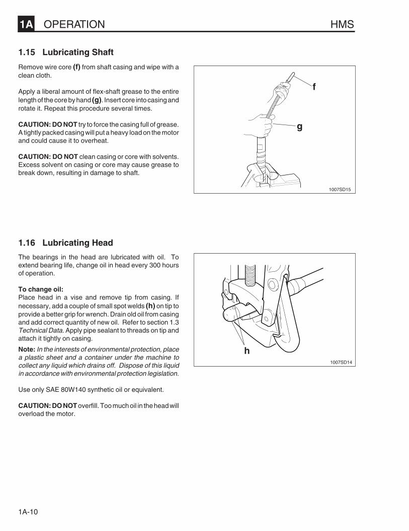
1.15 Lubricating Shaft
Remove wire core (f) from shaft casing and wipe with aclean cloth.
Apply a liberal amount of flex-shaft grease to the entirelength of the core by hand (g). Insert core into casing androtate it. Repeat this procedure several times.
CAUTION: DO NOT try to force the casing full of grease.A tightly packed casing will put a heavy load on the motorand could cause it to overheat.
CAUTION: DO NOT clean casing or core with solvents.Excess solvent on casing or core may cause grease tobreak down, resulting in damage to shaft.
h
1007SD15
1007SD14
1.16 Lubricating Head
The bearings in the head are lubricated with oil. Toextend bearing life, change oil in head every 300 hoursof operation.
To change oil:Place head in a vise and remove tip from casing. Ifnecessary, add a couple of small spot welds (h) on tip toprovide a better grip for wrench. Drain old oil from casingand add correct quantity of new oil. Refer to section 1.3Technical Data. Apply pipe sealant to threads on tip andattach it tightly on casing.
Note: In the interests of environmental protection, placea plastic sheet and a container under the machine tocollect any liquid which drains off. Dispose of this liquidin accordance with environmental protection legislation.
Use only SAE 80W140 synthetic oil or equivalent.
CAUTION: DO NOT overfill. Too much oil in the head willoverload the motor.

HMS OPERATION 1A
1A-11
1.17 Checking Head for Wear
Periodically measure the outside diameter of the headcasing (a) in the area of most noticeable wear.
Replace head if measured diameter is less than theminimum wear diameter.
NEW MINIMUMDIAMETER WEAR DIAMETER
in. (mm) in. (mm)
H25 1.00 (25) 0.88 (22)H35 1.38 (35) 1.25 (32)H45 1.75 (44) 1.63 (41)H55 2.25 (57) 2.13 (54)H65 2.50 (64) 2.38 (60)
PROBLEM REASON
Motor does not start. 1. Open circuit breaker or blown fuse on power supply.2. Brushes are worn too short. Replace.3. Switch on motor bad or wire connections loose.
Motor runs at normal speed 1. Air filter, screen, or vents clogged, blocking air flow.but overheats. 2. Too much grease in shaft.
3. Too much oil in head.
Motor runs at slow speed 1. Line voltage too low.and overheats. 2. Extension cord too small.
3. Head/shaft combination too large.4. Shaft not lubricated, core running dry.5. Head bearings binding. Inspect and replace.6. Rotor in motor rubbing.7. Motor bearings failed. Inspect and replace.
Motor noisy 1. Worn brushes. Brushes installed incorrectly.2. Worn motor bearings.3. Rotor in motor rubbing.
1.18 Troubleshooting
a
1008SD06

1A OPERATION HMS
1A-12
W
B
L
L
B
Y
2
4 5
W
6 1
3
B
7
W
BB
Y
2
4 5
W
6 1
3
B
W
B
7
1.19 Wiring Schematics
M1000 M2000 M3000
* NO GROUND WIRE
115V 5843 6305 584571597653
230V 5041 6551* 5800
230V 5494 54325495
M1000 M2000
230V 6590
M3000
1 SWITCH2 STATOR3 ROTOR4 LH BRUSH5 RH BRUSH6 RFI CAPACITOR7 INDUCTION COIL
B - BLACK or BROWNG - GREEN or GREEN W/
YELLOW STRIPEY - YELLOWW - WHITE or BLUE
1 SWITCH2 STATOR3 ROTOR4 LH BRUSH5 RH BRUSH6 RFI CAPACITOR7 INDUCTION COIL
B - BLACK or BROWNG - GREEN or GREEN W/
YELLOW STRIPEL - BLUEY - YELLOWW - WHITE or BLUE
1039SD16
1039SD17
NOT USED ON 6551
1023SD06
W
BB
2
4 5
W
1
3
G
W
1 SWITCH2 STATOR3 ROTOR4 LH BRUSH5 RH BRUSH
B - BLACK or BROWNG - GREEN or GREEN W/
YELLOW STRIPEW - WHITE or BLUE
EC - CONFORMITY CERTIFICATEEG-KONFORMITÄTS ERKLÄRUNG
CE-CERTIFICADO DE CONFORMIDADCERTIFICAT DE CONFORMITÉ DE LA CEE
WACKER CORPORATION - MENOMONEE FALLS, WISCONSIN USA
hereby certify that the construction equipment specified hereunderbescheinigt, daß das Baugerätcertifica que la máquina de construcciónatteste que le matériel
1. Category - Art - Categoría - Catégorie
2. Make - Fabrikmarke - Marca - Marque
3. Type - Typ - Tipo - Type
4. Type serial number of equipment / Gerätenummer innerhalb Typenserie-NummerNúmero de serie de la máquina / Numéro dans la série du type de matériel
has been produced in accordance with the following standardsin Übereinstimmung mit folgenden Richtlinien hergestellt worden istha sido fabricado en conformidad con las siguientes normasest produit conforme aux dispositions des directives européennes ci-après
EMC 89/336/EECEN 60555EN 55014MSD 89/392/EEC91/368/EEC93/44/EECHD 400IEC 745
File certificate carefullyBescheinigung bitte sorgfältig aufbewahrenConservar certificado cuidadosamenteConserver certificat soigneusement
QM1-3000
WACKER CORPORATIONN92 W15000 Anthony Avenue Menomonee Falls, Wisconsin53052-9007 USA (262) 255-0500 Fax (262) 255-0550
○ ○ ○ ○ ○ ○ ○ ○ ○ ○ ○ ○ ○ ○ ○ ○ ○ ○ ○ ○ ○ ○ ○ ○ ○ ○ ○ ○ ○ ○ ○ ○ ○ ○ ○
Internal VibratorInnenvibrator
Vibrador InternoVibrateur Interne
WACKER
M1000/230VM2000/115VM2000/230VM3000/230V
0005494, 0007653, 0005495,0006590
WACKER CORPORATION William Lahner Robert Motl


![1000 < : ~ 3000 < : B ; I · F g h ] h n m g d p b h g Z e v ON LINE ; I c _ j b c MRT MAC (“MACAN COMFORT”) 1000 : / 2000 < : / 3000 < : ... g Z j m r _ g b _ f b g k l j m d](https://img.pdfslide.us/doc/110x75/5eb4d6e9d5b698637d0107f5/1000-3000-b-i-f-g-h-h-n-m-g-d-p-b-h-g-z-e-v-on-line-i-c-.jpg)