Embed Size (px)
Citation preview

Avaya 9130 1000–3000 VAUninterruptible Power Systems
Site Preparation,Installation and Operator’s Manual
www.powerware.com/avaya


Avaya 9130 1000–3000 VAUninterruptible Power Systems
Site Preparation,Installation and Operator’s Manual
www.powerware.com/avaya
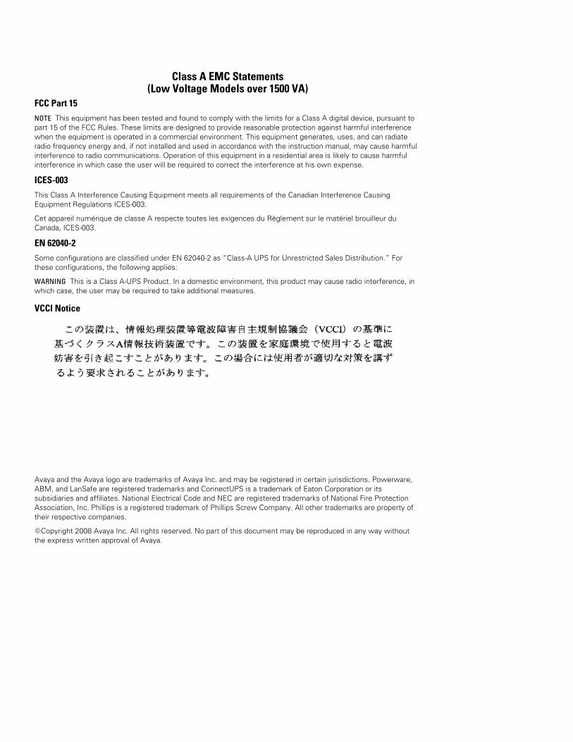
Class A EMC Statements(Low Voltage Models over 1500 VA)
FCC Part 15NOTE This equipment has been tested and found to comply with the limits for a Class A digital device, pursuant topart 15 of the FCC Rules. These limits are designed to provide reasonable protection against harmful interferencewhen the equipment is operated in a commercial environment. This equipment generates, uses, and can radiateradio frequency energy and, if not installed and used in accordance with the instruction manual, may cause harmfulinterference to radio communications. Operation of this equipment in a residential area is likely to cause harmfulinterference in which case the user will be required to correct the interference at his own expense.
ICES-003This Class A Interference Causing Equipment meets all requirements of the Canadian Interference CausingEquipment Regulations ICES-003.
Cet appareil numérique de classe A respecte toutes les exigences du Règlement sur le matériel brouilleur duCanada, ICES-003.
EN 62040-2Some configurations are classified under EN 62040-2 as “Class-A UPS for Unrestricted Sales Distribution.” Forthese configurations, the following applies:
WARNING This is a Class A-UPS Product. In a domestic environment, this product may cause radio interference, inwhich case, the user may be required to take additional measures.
VCCI Notice
Avaya and the Avaya logo are trademarks of Avaya Inc. and may be registered in certain jurisdictions. Powerware,ABM, and LanSafe are registered trademarks and ConnectUPS is a trademark of Eaton Corporation or itssubsidiaries and affiliates. National Electrical Code and NEC are registered trademarks of National Fire ProtectionAssociation, Inc. Phillips is a registered trademark of Phillips Screw Company. All other trademarks are property oftheir respective companies.
ECopyright 2008 Avaya Inc. All rights reserved. No part of this document may be reproduced in any way withoutthe express written approval of Avaya.
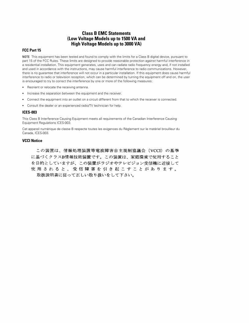
Class B EMC Statements(Low Voltage Models up to 1500 VA and
High Voltage Models up to 3000 VA)FCC Part 15NOTE This equipment has been tested and found to comply with the limits for a Class B digital device, pursuant topart 15 of the FCC Rules. These limits are designed to provide reasonable protection against harmful interference ina residential installation. This equipment generates, uses and can radiate radio frequency energy and, if not installedand used in accordance with the instructions, may cause harmful interference to radio communications. However,there is no guarantee that interference will not occur in a particular installation. If this equipment does cause harmfulinterference to radio or television reception, which can be determined by turning the equipment off and on, the useris encouraged to try to correct the interference by one or more of the following measures:
S Reorient or relocate the receiving antenna.
S Increase the separation between the equipment and the receiver.
S Connect the equipment into an outlet on a circuit different from that to which the receiver is connected.
S Consult the dealer or an experienced radio/TV technician for help.
ICES-003This Class B Interference Causing Equipment meets all requirements of the Canadian Interference CausingEquipment Regulations ICES-003.
Cet appareil numérique de classe B respecte toutes les exigences du Règlement sur le matériel brouilleur duCanada, ICES-003.
VCCI Notice
Requesting a Declaration of ConformityUnits that are labeled with a CE mark comply with the following harmonized standards and EU directives:
S Harmonized Standards: IEC 61000-3-12
S EU Directives: 73/23/EEC, Council Directive on equipment designed for use within certain voltage limits93/68/EEC, Amending Directive 73/23/EEC89/336/EEC, Council Directive relating to electromagnetic compatibility92/31/EEC, Amending Directive 89/336/EEC relating to EMC
The EC Declaration of Conformity is available upon request for products with a CE mark. For copies of the ECDeclaration of Conformity, contact:
Eaton Power Quality OyKoskelontie 13FIN-02920 EspooFinlandPhone: +358-9-452 661Fax: +358-9-452 665 68
Special SymbolsThe following are examples of symbols used on the UPS or accessories to alert you to importantinformation:
RISK OF ELECTRIC SHOCK - Observe the warning associated with the risk of electric shocksymbol.
CAUTION: REFER TO OPERATOR’S MANUAL - Refer to your operator’s manual for additionalinformation, such as important operating and maintenance instructions.
This symbol indicates that you should not discard the UPS or the UPS batteries in the trash. Thisproduct contains sealed, lead-acid batteries and must be disposed of properly. For more information,contact your local recycling/reuse or hazardous waste center.
This symbol indicates that you should not discard waste electrical or electronic equipment (WEEE) inthe trash. For proper disposal, contact your local recycling/reuse or hazardous waste center.
Avaya 9130 1000–3000 VA UPS Site Preparation, Installation and Operator’s Manual S 164201765 Rev 1 i
Table of Contents
1 Introduction 1. . . . . . . . . . . . . . . . . . . . . . . . . . . . . . . . . . . . . . . . . . . . . . . . . . . . . . . . .
2 Safety Warnings 3. . . . . . . . . . . . . . . . . . . . . . . . . . . . . . . . . . . . . . . . . . . . . . . . . . . . .
3 Installation 17. . . . . . . . . . . . . . . . . . . . . . . . . . . . . . . . . . . . . . . . . . . . . . . . . . . . . . . . . .Inspecting the Equipment 17. . . . . . . . . . . . . . . . . . . . . . . . . . . . . . . . . . . . . . . . . . . . . . . . . . . . . . . . . . . . . . . .Unpacking the Cabinet 18. . . . . . . . . . . . . . . . . . . . . . . . . . . . . . . . . . . . . . . . . . . . . . . . . . . . . . . . . . . . . . . . . .Checking the Accessory Kit 18. . . . . . . . . . . . . . . . . . . . . . . . . . . . . . . . . . . . . . . . . . . . . . . . . . . . . . . . . . . . . .Installation 19. . . . . . . . . . . . . . . . . . . . . . . . . . . . . . . . . . . . . . . . . . . . . . . . . . . . . . . . . . . . . . . . . . . . . . . . . .
Checking the Rail Kit Accessories 19. . . . . . . . . . . . . . . . . . . . . . . . . . . . . . . . . . . . . . . . . . . . . . . . . . . . . . .Tools Required 19. . . . . . . . . . . . . . . . . . . . . . . . . . . . . . . . . . . . . . . . . . . . . . . . . . . . . . . . . . . . . . . . . . . . .Rackmount Setup 20. . . . . . . . . . . . . . . . . . . . . . . . . . . . . . . . . . . . . . . . . . . . . . . . . . . . . . . . . . . . . . . . . . .
Wiring Installation 23. . . . . . . . . . . . . . . . . . . . . . . . . . . . . . . . . . . . . . . . . . . . . . . . . . . . . . . . . . . . . . . . . . . . .Installing the UPS 23. . . . . . . . . . . . . . . . . . . . . . . . . . . . . . . . . . . . . . . . . . . . . . . . . . . . . . . . . . . . . . . . . .Connecting the EBM(s) 26. . . . . . . . . . . . . . . . . . . . . . . . . . . . . . . . . . . . . . . . . . . . . . . . . . . . . . . . . . . . . . .
UPS Initial Startup 29. . . . . . . . . . . . . . . . . . . . . . . . . . . . . . . . . . . . . . . . . . . . . . . . . . . . . . . . . . . . . . . . . . . . .
4 Operation 33. . . . . . . . . . . . . . . . . . . . . . . . . . . . . . . . . . . . . . . . . . . . . . . . . . . . . . . . . . .Control Panel Functions 33. . . . . . . . . . . . . . . . . . . . . . . . . . . . . . . . . . . . . . . . . . . . . . . . . . . . . . . . . . . . . . . . .
Changing the Language 34. . . . . . . . . . . . . . . . . . . . . . . . . . . . . . . . . . . . . . . . . . . . . . . . . . . . . . . . . . . . . .Display Functions 34. . . . . . . . . . . . . . . . . . . . . . . . . . . . . . . . . . . . . . . . . . . . . . . . . . . . . . . . . . . . . . . . . . .User Settings 36. . . . . . . . . . . . . . . . . . . . . . . . . . . . . . . . . . . . . . . . . . . . . . . . . . . . . . . . . . . . . . . . . . . . . .
Operating Modes 39. . . . . . . . . . . . . . . . . . . . . . . . . . . . . . . . . . . . . . . . . . . . . . . . . . . . . . . . . . . . . . . . . . . . .Normal Mode 39. . . . . . . . . . . . . . . . . . . . . . . . . . . . . . . . . . . . . . . . . . . . . . . . . . . . . . . . . . . . . . . . . . . . .Battery Mode 39. . . . . . . . . . . . . . . . . . . . . . . . . . . . . . . . . . . . . . . . . . . . . . . . . . . . . . . . . . . . . . . . . . . . .Bypass Mode 40. . . . . . . . . . . . . . . . . . . . . . . . . . . . . . . . . . . . . . . . . . . . . . . . . . . . . . . . . . . . . . . . . . . . . .Standby Mode 40. . . . . . . . . . . . . . . . . . . . . . . . . . . . . . . . . . . . . . . . . . . . . . . . . . . . . . . . . . . . . . . . . . . . .
UPS Startup and Shutdown 41. . . . . . . . . . . . . . . . . . . . . . . . . . . . . . . . . . . . . . . . . . . . . . . . . . . . . . . . . . . . . .Starting the UPS 41. . . . . . . . . . . . . . . . . . . . . . . . . . . . . . . . . . . . . . . . . . . . . . . . . . . . . . . . . . . . . . . . . . .Starting the UPS on Battery 42. . . . . . . . . . . . . . . . . . . . . . . . . . . . . . . . . . . . . . . . . . . . . . . . . . . . . . . . . . .UPS Shutdown 42. . . . . . . . . . . . . . . . . . . . . . . . . . . . . . . . . . . . . . . . . . . . . . . . . . . . . . . . . . . . . . . . . . . . .
Transferring the UPS Between Modes 43. . . . . . . . . . . . . . . . . . . . . . . . . . . . . . . . . . . . . . . . . . . . . . . . . . . . . . .Retrieving the Event Log 43. . . . . . . . . . . . . . . . . . . . . . . . . . . . . . . . . . . . . . . . . . . . . . . . . . . . . . . . . . . . . . . .Setting Power Strategy 43. . . . . . . . . . . . . . . . . . . . . . . . . . . . . . . . . . . . . . . . . . . . . . . . . . . . . . . . . . . . . . . . .Configuring Bypass Settings 44. . . . . . . . . . . . . . . . . . . . . . . . . . . . . . . . . . . . . . . . . . . . . . . . . . . . . . . . . . . . . .Configuring Load Segments 45. . . . . . . . . . . . . . . . . . . . . . . . . . . . . . . . . . . . . . . . . . . . . . . . . . . . . . . . . . . . . .
TABLE OF CONTENTS
Avaya 9130 1000–3000 VA UPS Site Preparation, Installation and Operator’s Manual S 164201765 Rev 1ii
Configuring Battery Settings 46. . . . . . . . . . . . . . . . . . . . . . . . . . . . . . . . . . . . . . . . . . . . . . . . . . . . . . . . . . . . . .Configuring the UPS for EBMs 46. . . . . . . . . . . . . . . . . . . . . . . . . . . . . . . . . . . . . . . . . . . . . . . . . . . . . . . . . .Running Battery Tests 47. . . . . . . . . . . . . . . . . . . . . . . . . . . . . . . . . . . . . . . . . . . . . . . . . . . . . . . . . . . . . . .Configuring Automatic Restart 48. . . . . . . . . . . . . . . . . . . . . . . . . . . . . . . . . . . . . . . . . . . . . . . . . . . . . . . . .
5 Communication 49. . . . . . . . . . . . . . . . . . . . . . . . . . . . . . . . . . . . . . . . . . . . . . . . . . . . . .Installing Communication Options and Control Terminals 50. . . . . . . . . . . . . . . . . . . . . . . . . . . . . . . . . . . . . . . . .Communication Options 50. . . . . . . . . . . . . . . . . . . . . . . . . . . . . . . . . . . . . . . . . . . . . . . . . . . . . . . . . . . . . . . . .
RS-232 and USB Communication Ports 50. . . . . . . . . . . . . . . . . . . . . . . . . . . . . . . . . . . . . . . . . . . . . . . . . . . .ConnectUPS-BD Web/SNMP Card 52. . . . . . . . . . . . . . . . . . . . . . . . . . . . . . . . . . . . . . . . . . . . . . . . . . . . . . .Remote Emergency Power-off 53. . . . . . . . . . . . . . . . . . . . . . . . . . . . . . . . . . . . . . . . . . . . . . . . . . . . . . . . . .Relay Output Contacts 54. . . . . . . . . . . . . . . . . . . . . . . . . . . . . . . . . . . . . . . . . . . . . . . . . . . . . . . . . . . . . . .Programmable Signal Inputs 55. . . . . . . . . . . . . . . . . . . . . . . . . . . . . . . . . . . . . . . . . . . . . . . . . . . . . . . . . . .
Modem Operation 57. . . . . . . . . . . . . . . . . . . . . . . . . . . . . . . . . . . . . . . . . . . . . . . . . . . . . . . . . . . . . . . . . . . . .Powerware LanSafe Power Management Software 57. . . . . . . . . . . . . . . . . . . . . . . . . . . . . . . . . . . . . . . . . . . . .
6 UPS Maintenance 59. . . . . . . . . . . . . . . . . . . . . . . . . . . . . . . . . . . . . . . . . . . . . . . . . . . .UPS and Battery Care 59. . . . . . . . . . . . . . . . . . . . . . . . . . . . . . . . . . . . . . . . . . . . . . . . . . . . . . . . . . . . . . . . . .Storing the UPS and Batteries 59. . . . . . . . . . . . . . . . . . . . . . . . . . . . . . . . . . . . . . . . . . . . . . . . . . . . . . . . . . . .When to Replace Batteries 60. . . . . . . . . . . . . . . . . . . . . . . . . . . . . . . . . . . . . . . . . . . . . . . . . . . . . . . . . . . . . . .Replacing Batteries 60. . . . . . . . . . . . . . . . . . . . . . . . . . . . . . . . . . . . . . . . . . . . . . . . . . . . . . . . . . . . . . . . . . . .
Replacing UPS Internal Batteries 61. . . . . . . . . . . . . . . . . . . . . . . . . . . . . . . . . . . . . . . . . . . . . . . . . . . . . . . .Replacing EBMs 64. . . . . . . . . . . . . . . . . . . . . . . . . . . . . . . . . . . . . . . . . . . . . . . . . . . . . . . . . . . . . . . . . . . .
Testing New Batteries 66. . . . . . . . . . . . . . . . . . . . . . . . . . . . . . . . . . . . . . . . . . . . . . . . . . . . . . . . . . . . . . . . . .Recycling the Used Battery or UPS 67. . . . . . . . . . . . . . . . . . . . . . . . . . . . . . . . . . . . . . . . . . . . . . . . . . . . . . . . .Updating the UPS Firmware 67. . . . . . . . . . . . . . . . . . . . . . . . . . . . . . . . . . . . . . . . . . . . . . . . . . . . . . . . . . . . . .
7 Specifications 69. . . . . . . . . . . . . . . . . . . . . . . . . . . . . . . . . . . . . . . . . . . . . . . . . . . . . . .Model Specifications 69. . . . . . . . . . . . . . . . . . . . . . . . . . . . . . . . . . . . . . . . . . . . . . . . . . . . . . . . . . . . . . . . . . .Rear Panels 76. . . . . . . . . . . . . . . . . . . . . . . . . . . . . . . . . . . . . . . . . . . . . . . . . . . . . . . . . . . . . . . . . . . . . . . . .
8 Troubleshooting 79. . . . . . . . . . . . . . . . . . . . . . . . . . . . . . . . . . . . . . . . . . . . . . . . . . . . . .Typical Alarms and Conditions 79. . . . . . . . . . . . . . . . . . . . . . . . . . . . . . . . . . . . . . . . . . . . . . . . . . . . . . . . . . . .Silencing the Alarm 83. . . . . . . . . . . . . . . . . . . . . . . . . . . . . . . . . . . . . . . . . . . . . . . . . . . . . . . . . . . . . . . . . . . .Obtaining Service 83. . . . . . . . . . . . . . . . . . . . . . . . . . . . . . . . . . . . . . . . . . . . . . . . . . . . . . . . . . . . . . . . . . . . .Parts List 83. . . . . . . . . . . . . . . . . . . . . . . . . . . . . . . . . . . . . . . . . . . . . . . . . . . . . . . . . . . . . . . . . . . . . . . . . . .
Avaya 9130 1000–3000 VA UPS Site Preparation, Installation and Operator’s Manual S 164201765 Rev 1 1
Chapter 1 Introduction
The Avaya® 9130 uninterruptible power system (UPS) protects yoursensitive electronic equipment from the most common power problems,including power failures, power sags, power surges, brownouts, linenoise, high voltage spikes, frequency variations, switching transients,and harmonic distortion.
Power outages can occur when you least expect it and powerquality can be erratic. These power problems have the potential tocorrupt critical data, destroy unsaved work sessions, and damagehardware — causing hours of lost productivity and expensive repairs.
With the Avaya 9130, you can safely eliminate the effects of powerdisturbances and guard the integrity of your equipment. Providingoutstanding performance and reliability, the Avaya 9130’s uniquebenefits include:
S True online double-conversion technology with high power density,utility frequency independence, and generator compatibility.
S Rackmount models in a space-optimizing 2U size that fits anystandard 48 cm (19”) rack.
S ABM® technology that uses advanced battery management toincrease battery service life, optimize recharge time, and provide awarning before the end of useful battery life.
S Selectable High Efficiency mode of operation.
S Emergency shutdown control through the Remote EmergencyPower-off (REPO) port.
S Network power management with the ConnectUPS -BD Web/SNMPCard. This internal card has SNMP and HTTP capabilities as well asmonitoring through a Web browser interface; connects to atwisted-pair Ethernet (10/100BaseT) network.
S Additional communication options: one RS-232 communication port,one USB communication port, and relay output contacts.
S Optional modem capability for remote monitoring and service.
S Extended runtime with Extended Battery Modules (EBMs).
S Firmware that is easily upgradable without a service call.
S Backed by worldwide agency approvals.
t
INTRODUCTION
Avaya 9130 1000–3000 VA UPS Site Preparation, Installation and Operator’s Manual S 164201765 Rev 12
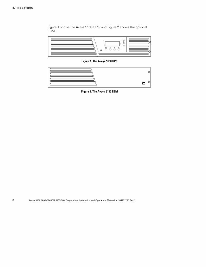
Figure 1 shows the Avaya 9130 UPS, and Figure 2 shows the optionalEBM.
Figure 1. The Avaya 9130 UPS
Figure 2. The Avaya 9130 EBM
Avaya 9130 1000–3000 VA UPS Site Preparation, Installation and Operator’s Manual S 164201765 Rev 1 3
Chapter 2 Safety Warnings
IMPORTANT SAFETY INSTRUCTIONSSAVE THESE INSTRUCTIONS
This manual contains important instructions that you should follow during installation andmaintenance of the UPS and batteries. Please read all instructions before operating theequipment and save this manual for future reference.
DANGERThis UPS contains LETHAL VOLTAGES. All repairs and service should be performed byAUTHORIZED SERVICE PERSONNEL ONLY. There are NO USER SERVICEABLE PARTSinside the UPS.
WARNINGS This UPS contains its own energy source (batteries). The UPS output may carry live
voltage even when the UPS is not connected to an AC supply.
S To reduce the risk of fire or electric shock, install this UPS in a temperature and humiditycontrolled, indoor environment, free of conductive contaminants. Ambient temperaturemust not exceed 40°C (104°F). Do not operate near water or excessive humidity(90% maximum).
S To reduce the risk of fire, connect only to a circuit provided with branch circuitovercurrent protection in accordance with the National Electrical Code® (NEC®),ANSI/NFPA 70.
S Output overcurrent protection and disconnect switch must be provided by others.
S To comply with international standards and wiring regulations, the sum of the leakagecurrent of the UPS and the total equipment connected to the output of this UPS must nothave an earth leakage current greater than 3.5 milliamperes.
S If installing optional rackmount EBM(s), install the EBM(s) directly below the UPS so thatall wiring between the cabinets is installed behind the front covers and is inaccessible tousers. The maximum number of EBM(s) per UPS is four.
S If the UPS requires any type of transportation, verify that the UPS is unplugged andturned off and then disconnect the UPS internal battery connector (see Figure 20 onpage 62).
SAFETY WARNINGS
Avaya 9130 1000–3000 VA UPS Site Preparation, Installation and Operator’s Manual S 164201765 Rev 14
CAUTIONS Batteries can present a risk of electrical shock or burn from high short-circuit current.
Observe proper precautions. Servicing should be performed by qualified servicepersonnel knowledgeable of batteries and required precautions. Keep unauthorizedpersonnel away from batteries.
S Proper disposal of batteries is required. Refer to your local codes for disposalrequirements.
S Never dispose of batteries in a fire. Batteries may explode when exposed to flame.
Sikkerhedsanvisninger
VIGTIGE SIKKERHEDSANVISNINGERGEM DISSE ANVISNINGER
Denne manual indeholder vigtige instruktioner, som skal følges under installation ogvedligeholdelse af UPS’en og batterierne. Læs venligst alle instruktioner inden betjening afudstyret og gem denne manual mhp. fremtidige opslag.
FAREDenne UPS indeholder LIVSFARLIG HØJSPÆNDING. Alle reparationer og vedligeholdelse børkun udføres af en AUTORISERET SERVICETEKNIKER. Ingen af UPS’ens indvendige dele kanrepareres af brugeren.
ADVARSEL!S Denne UPS indeholder sin egen energikilde (batterier). Udgangsstikket på UPS’en kan
endog være strømførende, når UPS’en ikke er koblet til en vekselstrømsforsyning.
S Installér denne UPS i et temperatur- og fugtighedskontrolleret indendørsmiljø, frit forledende forureningsstoffer for at formindske risikoen for brand og elektrisk stød.Rumtemperaturen må ikke overstige 40°C. UPS’en bør ikke betjenes nær vand eller højfugtighed (maksimalt 90%).
S For at reducere risikoen for brand må tilkobling kun ske til et kredsløb forsynet med100 ampere maks. linieforgrenings overbelastningsbeskyttelse i overensstemmelse medNEC, ANSI/NFPA 70.
S Udgangsoverbelastningsbeskyttelsen og afbryderkontakten skal leveres af andre.
S I overensstemmelse med internationale normer og bestemmelser for el-installation mådet udstyr, der er forbundet til udgangen af denne UPS, tilsammen ikke overskride enjordafdelingsspænding på mere end 3,5 milliampere.
SAFETY WARNINGS
Avaya 9130 1000–3000 VA UPS Site Preparation, Installation and Operator’s Manual S 164201765 Rev 1 5
ADVARSELS Batterierne kan give risiko for elektrisk stød eller brandsår forårsaget af høj
kortslutningsstrøm. Overhold gældende forsigtighedsregler. Servicering skal udføres afkvalificeret servicepersonale med kendskab til batterier og gældende forsigtighedsregler.Hold uautoriseret personale væk fra batterierne.
S Korrekt bortskaffelse af batterier er påkrævet. Overhold gældende lokale regler forbortskaffelsesprocedurer.
S Skaf dig aldrig af med batterierne ved at brænde dem. Batterierne kan eksplodere vedåben ild.
Belangrijke Veiligheidsinstructies
BELANGRIJKE VEILIGHEIDSINSTRUCTIESBEWAAR DEZE INSTRUCTIES
Deze handleiding bevat belangrijke instructies die u dient te volgen tijdens de installatie enhet onderhoud van de UPS en de accu’s. Lees alle instructies voordat u de apparatuur inbedrijf neemt en bewaar deze handleiding als naslagwerk.
GEVAARDeze UPS bevat LEVENSGEVAARLIJKE ELEKTRISCHE SPANNING. Alle reparaties enonderhoud dienen UITSLUITEND DOOR ERKEND SERVICEPERSONEEL te worden uitgevoerd.Er bevinden zich GEEN ONDERDELEN in de UPS die DOOR DE GEBRUIKER kunnen wordenGEREPAREERD.
WAARSCHUWINGS Deze UPS bevat een eigen energiebron (accu’s). De UPS-uitgang kan onder spanning
staan, zelfs wanneer de UPS niet is aangesloten op de netspanning.
S Teneinde de kans op brand of elektrische schok te verminderen dient deze UPS in eengebouw met temperatuur- en vochtigheidregeling te worden geïnstalleerd, waar geengeleidende verontreinigingen aanwezig zijn. De omgevingstemperatuur mag 40°C nietoverschrijden. Niet gebruiken in de buurt van water of bij zeer hoge vochtigheid(max. 90%).
S Sluit om brandgevaar te voorkomen de apparatuur uitsluitend aan op een circuit voorzienvan een overstroombeveiliging voor vertakte circuits van maximaal 100 A inovereenstemming met de NEC (Nationale Elektriciteitsvoorschriften), ANSI/NFPA 70.
SAFETY WARNINGS
Avaya 9130 1000–3000 VA UPS Site Preparation, Installation and Operator’s Manual S 164201765 Rev 16
S De uitgangsoverstroombeveiliging en de stroomonderbreker moeten door derden wordengeleverd.
S Om aan de internationale normen en bedradingsvoorschriften te voldoen mag de geheleapparatuur die op de uitgang van deze UPS is aangesloten, geen aardlekstroom vanmeer dan 3,5 milliampère hebben.
OPGELETS Batterijen leveren gevaar op voor elektrische schokken en kunnen brandwonden
veroorzaken door een grote kortsluitstroom. Neem de juiste voorzorgsmaatregelen inacht. Het onderhoud moet worden uitgevoerd door bevoegde onderhoudsmonteurs dieverstand hebben van accu’s en op de hoogte zijn van de vereiste voorzorgsmaatregelen.Houd onbevoegden uit de buurt van de accu’s.
S De batterijen moeten op de juiste wijze worden opgeruimd. Raadpleeg hiervoor uwplaatselijke voorschriften.
S Nooit batterijen in het vuur gooien. De batterijen kunnen ontploffen.
Tarkeita Turvaohjeita
TÄRKEITÄ TURVAOHJEITA - SUOMISÄILYTÄ NÄMÄ OHJEET
Tämä käyttöohje sisältää tärkeitä ohjeita, joita on noudatettava UPS-virtalähteen ja akkujenasennuksen ja huollon yhteydessä. Lue kaikki ohjeet ennen laitteiston käyttöä ja säilytä ohjemyöhempää tarvetta varten.
VAARATämä UPS sisältää HENGENVAARALLISIA JÄNNITTEITÄ. Kaikki korjaukset ja huollot onjätettävä VAIN VALTUUTETUN HUOLTOHENKILÖN TOIMEKSI. UPS ei sisällä MITÄÄNKÄYTTÄJÄN HUOLLETTAVIA OSIA.
VAROITUSS Tässä UPS-virtalähteessä on oma energianlähde (akut). UPS-virtalähteen lähdössä voi
olla jännite, vaikka UPS-virtalähdettä ei ole kytketty verkkovirtaan.
S Vähentääksesi tulipalon ja sähköiskun vaaraa asenna tämä UPS sisätiloihin,joissa lämpötila ja kosteus on säädettävissä ja joissa ei ole virtaa johtaviaepäpuhtauksia. Ympäristön lämpötila ei saa ylittää 40 °C. Älä käytä lähellä vettä ja vältäkosteita tiloja (95 % maksimi).
SAFETY WARNINGS
Avaya 9130 1000–3000 VA UPS Site Preparation, Installation and Operator’s Manual S 164201765 Rev 1 7
S Pienennä tulipalon vaaraa kytkemällä vain piiriin, jossa on 100 ampeerinmaksimihaarapiirin ylivirtasuoja kansallisen sähkölainsäädännön (ANSI/NFPA 70)mukaan.
S Muiden on toimitettava lähdön ylivirtasuoja ja irtikytkentäkytkin.
S Kansainväliset normit ja johdotusmääräykset vaativat, että kaikkien tämän UPS-laitteenulostulokytkentöjen yhteinen maavuotovirta ei ylitä 3,5 milliampeeria (mA).
VAROS Akut voivat aiheuttaa sähköiskun tai palovammojen vaaran johtuen suuresta
oikosulkuvirrasta. Noudata kaikkia asianmukaisia varotoimia. Laitteen saa huoltaa vainammattitaitoinen huoltohenkilökunta, joka tuntee akut ja niihin liittyvät varotoimet. Äläpäästä valtuuttamatonta henkilöstöä lähelle akkuja.
S Akusto täytyy hävittää säädösten mukaisella tavalla. Noudata paikallisia määräyksiä.
S Älä koskaan heitä akkuja tuleen. Ne voivat räjähtää.
Consignes de sécurité
CONSIGNES DE SÉCURITÉ IMPORTANTESCONSERVER CES INSTRUCTIONS
Ce manuel comporte des instructions importantes que vous êtes invité à suivre lors de touteprocédure d’installation et de maintenance des batteries et de l’onduleur. Veuillez consulterentièrement ces instructions avant de faire fonctionner l’équipement et conserver ce manuelafin de pouvoir vous y reporter ultérieurement.
DANGER!Cet onduleur contient des TENSIONS MORTELLES. Toute opération d’entretien et deréparation doit être EXCLUSIVEMENT CONFIÉE A UN PERSONNEL QUALIFIÉ AGRÉÉ.AUCUNE PIÈCE RÉPARABLE PAR L’UTILISATEUR ne se trouve dans l’onduleur.
AVERTISSEMENT!S Cette onduleur possède sa propre source d’alimentation (batteries). Il est possible que la
sortie de l’onduleur soit sous tension même lorsque l’onduleur n’est pas connectée à unealimentation CA.
S Pour réduire les risques d’incendie et de décharge électrique, installer l’onduleuruniquement à l’intérieur, dans un lieu dépourvu de matériaux conducteurs, où latempérature et l’humidité ambiantes sont contrôlées. La température ambiante ne doitpas dépasser 40 °C. Ne pas utiliser à proximité d’eau ou dans une atmosphèreexcessivement humide (95 % maximum).
SAFETY WARNINGS
Avaya 9130 1000–3000 VA UPS Site Preparation, Installation and Operator’s Manual S 164201765 Rev 18
S Afin de réduire les risques d’incendie, ne raccordez qu’à un circuit muni d’une protectionde surintensité du circuit de dérivation maximum de 100 ampères conformément au NEC(Code Électrique National) des États-Unis, ANSI/NFPA 70.
S La protection de surintensité de sortie ainsi que le sectionneur doivent être fournis pardes tiers.
S Afin d’être conforme aux normes et règlements internationaux de câblage, le courant defuite à la terre de la totalité du matériel branché sur la sortie de l’onduleur ne doit pasdépasser 3,5 mA.
ATTENTION!S Les batteries peuvent présenter un risque de choc électrique ou de brûlure provenant
d’un courant de court-circuit haute intensité. Observez les précautions appropriées.L’entretien doit être réalisé par du personnel qualifié connaissant bien les batteries etles précautions nécessaires. N’autorisez aucun personnel non qualifié à manipuler lesbatteries.
S Une mise au rebut réglementaire des batteries est obligatoire. Consulter les règlementsen vigueur dans votre localité.
S Ne jamais jeter les batteries au feu. L’exposition aux flammes risque de les faireexploser.
Sicherheitswarnungen
WICHTIGE SICHERHEITSANWEISUNGENAUFBEWAREN
Dieses Handbuch enthält wichtige Anweisungen, die Sie während der Installation undWartung des USV (Unterbrechungsfreies Stromversorgungssystem) und der Batterienbefolgen müssen. Bitte lesen Sie alle Anweisungen des Handbuches bevor sie mit demGerät arbeiten. Bewaren Sie das Handbuch zum Nachlesen auf.
WARNUNGDie USV führt lebensgefährliche Spannungen. Alle Reparatur- und Wartungsarbeiten solltennur von Kundendienstfachleuten durchgeführt werden. Die USV enthält keine vom Benutzerzu wartenden Komponenten.
SAFETY WARNINGS
Avaya 9130 1000–3000 VA UPS Site Preparation, Installation and Operator’s Manual S 164201765 Rev 1 9
ACHTUNGS Dieses USV (Unterbrechungsfreies Stromversorgungssystem) enthält eine eigene
Energiequelle (Batterien). Der USV-Ausgang kann Spannung führen, auch wenn das USVnicht an eine Wechselstromquelle angeschlossen ist.
S Um die Brand- oder Elektroschockgefahr zu verringern, diese USV nur in Gebäuden mitkontrollierter Temperatur und Luftfeuchtigkeit installieren, in denen keine leitendenSchmutzstoffen vorhanden sind. Die Umgebungstemperatur darf 40°C nicht übersteigen.Die USV nicht in der Nähe von Wasser oder in extrem hoher Luftfeuchtigkeit (max. 95 %)betreiben.
S Um die Brandgefahr zu verringern, nur an eine Leitung anschließen, die mit einemÜberlaststromschutz von maximal 100 Ampere in Übereinstimmung mit dem NEC,ANSI/NFPA 70 ausgestattet ist.
S Der Ausgangs-Überlaststromschutz und der Trennschalter müssen von anderenHerstellern geliefert werden.
S Um internationale Normen und Verdrahtungsvorschriften zu erfüllen, dürfen die an denAusgang dieser USV angeschlossenen Geräte zusammen einen Erdableitstrom voninsgesamt 3,5 Milliampere nicht überschreiten.
VORSICHT!S Batterien können das Risiko eines elektrischen Schlags bergen oder durch hohen
Kurzschlussstrom in Brand geraten. Die richtigen Vorsichtsmaßnahmen beachten. DieWartung muss von qualifiziertem Wartungspersonal durchgeführt werden, das imUmgang mit Batterien geübt ist und über gute Kenntnisse der erforderlichenVorsichtsmaßnahmen verfügt. Nicht autorisiertes Personal von Batterien fern halten.
S Die Batterien müssen ordnungsgemäß entsorgt werden. Hierbei sind die örtlichenBestimmungen zu beachten.
S Batterien niemals verbrennen, da sie explodieren können.
Avvisi di sicurezza
IMPORTANTI ISTRUZIONI DI SICUREZZACONSERVARE QUESTE ISTRUZIONI
Il presente manuale contiene importanti istruzioni da seguire durante l’installazione e lamanutenzione dell’UPS e delle batterie. Leggere integralmente le istruzioni prima diutilizzare l’apparecchiatura e conservare il presente manuale per futuro riferimento.
SAFETY WARNINGS
Avaya 9130 1000–3000 VA UPS Site Preparation, Installation and Operator’s Manual S 164201765 Rev 110
PERICOLOLa TENSIONE contenuta in questo gruppo statico di continuità è LETALE. Tutte le operazionidi riparazione e di manutenzione devono essere effettuate ESCLUSIVAMENTE DAPERSONALE TECNICO AUTORIZZATO. All’interno del gruppo statico di continuità NON visono PARTI RIPARABILI DALL’UTENTE.
AVVERTENZAS L’UPS contiene la propria fonte di energia (batterie). Le prese d’uscita dell’UPS possono
essere sotto tensione anche quando l’UPS non è collegato all’alimentazione elettrica CA.
S Per ridurre il rischio di incendio o di scossa elettrica, installare il gruppo statico dicontinuità in un ambiente interno a temperatura ed umidità controllata, privo di agenticontaminanti conduttivi. La temperatura ambiente non deve superare i 40°C. Nonutilizzare l’unità in prossimità di acqua o in presenza di umidità eccessiva (90% max).
S Per ridurre il rischio di incendio, effettuare il collegamento soltanto a un circuito dotatodi una protezione da sovraccarico per il circuito derivato di max. 100 ampere comestabilito dalle norme statunitensi sugli impianti elettrici (NEC, ANSI/NFPA 70).
S La protezione da sovraccarico per le uscite e l’interruttore di scollegamento devonoessere forniti da altri produttori.
S Per conformità con gli standard internazionali e con le norme in merito al cablaggio, tuttal’apparecchiatura collegata con l’uscita del gruppo statico di continuità non deve avereuna corrente di dispersione di terra superiore a 3,5 milliampere.
ATTENZIONES Le batterie possono comportare un rischio di scossa elettrica o di ustione in seguito a
un’elevata corrente di corto circuito. Osservare le dovute precauzioni. L’assistenza deveessere eseguita da personale qualificato esperto di batterie e delle necessarieprecauzioni. Tenere il personale non autorizzato lontano dalle batterie.
S Le batterie devono essere smaltite in modo corretto. Per i requisiti di smaltimento fareriferimento alle disposizioni locali.
S Non gettare mai le batterie nel fuoco poichè potrebbero esplodere se esposte allefiamme.
SAFETY WARNINGS
Avaya 9130 1000–3000 VA UPS Site Preparation, Installation and Operator’s Manual S 164201765 Rev 1 11
Viktig Sikkerhetsinformasion
VIKTIGE SIKKERHETSINSTRUKSJONERGJEM DISSE INSTRUKSJONENE
Denne håndboken inneholder viktige instruksjoner som du bør overholde ved montering ogvedlikehold av UPS-enheten og batteriene. Les alle instruksjoner før utstyret tas i bruk, oggjem håndboken til fremtidig referanse.
FARLIGDenne UPS’en inneholder LIVSFARLIGE SPENNINGER. All reparasjon og service må kunutføres av AUTORISERT SERVICEPERSONALE. BRUKERE KAN IKKE UTFØRE SERVICE PÅNOEN AV DELENE i UPS’en.
FARLIGS UPS-enheten inneholder sin egen energikilde (batterier). UPS-utgangen kan være
strømførende selv når UPS-enheten ikke er koblet til et strømuttak.
S For å redusere fare for brann eller elektriske støt, bør denne UPS’en installeres i etinnendørs miljø med kontrollert temperatur og luftfuktighet som er fritt for ledende,forurensende stoffer. Romtemperaturen må ikke overskride 40°C. Den må ikke brukes inærheten av vann eller ved meget høy luftfuktighet (90% maks.).
S For å redusere brannfaren skal det bare kobles til et kretsløp med 100 A maksimumlinjeforgrenings overbelastningsbeskyttelse i henhold til NEC, ANSI/NFPA 70.
S Overbelastningsbeskyttelse for strømutgang og bryterkontakt skal leveres av andre.
S Alt utstyr som er forbundet med utgangen av denne UPS’en må ikke ha en sterkere totallekkasjestrøm enn 3,5 milliampere for å være i overensstemmelse med internasjonalestandarder og forkablingsbestemmelser.
FORSIKTIGS Batterier kan utgjøre en fare for elektrisk støt eller brannsår pga. høy kortsluttingsstrøm.
Treff passende forholdsregler. Service bør utføres av kvalifisert servicepersonale medkjennskap til batterier og nødvendige forholdsregler. Hold uautorisert personale borte frabatteriene.
S Batterier må fjernes på korrekt måte. Se lokale forskrifter vedrørende krav om fjerning avbatterier.
S Kast aldri batterier i flammer, da de kan eksplodere, hvis de utsettes for åpen ild.
SAFETY WARNINGS
Avaya 9130 1000–3000 VA UPS Site Preparation, Installation and Operator’s Manual S 164201765 Rev 112
Regulamentos de Segurança
INSTRUÇÕES DE SEGURANÇA IMPORTANTESGUARDE ESTAS INSTRUÇÕES
Este manual contém instruções importantes que devem ser seguidas durante a instalação emanutenção do no-break e das baterias. Leia todas as instruções antes de operar oequipamento e guarde este manual para consultá-lo futuramente.
CUIDADOA UPS contém VOLTAGEM MORTAL. Todos os reparos e assistência técnica devem serexecutados SOMENTE POR PESSOAL DA ASSISTÊNCIA TÉCNICA AUTORIZADO. Não hánenhuma PEÇA QUE POSSA SER REPARADA PELO USUÁRIO dentro da UPS.
ADVERTÊNCIAS Este no-break possui sua própria fonte de energia (baterias). A saída do no-break pode
estar energizada mesmo que este não esteja conectado a uma fonte de energia elétrica.
S Para reduzir o risco de incêndios ou choques elétricos, instale a UPS em ambienteinterno com temperatura e umidade controladas e livres de contaminadores condutíveis.A temperatura ambiente não deve exceder 40°C. Não opere próximo a água ou emumidade excessiva (máx: 90%).
S Para reduzir o risco de incêndio, conecte somente ao circuito fornecido com a proteçãomáxima de 100 ampères contra a sobretensão do circuito derivado, de acordo com anorma ANSI/NFPA 70 do NEC.
S A proteção contra a sobretensão de saída e o disjuntor deve ser fornecida por terceiros.
S Para estar de acordo com os padrões internacionais e os regulamentos de fiação, oequipamento total conectado à saída desta UPS não deve ter uma corrente de fuga àterra maior que 3,5 miliampères.
PERIGOS As baterias podem oferecer risco de choque elétrico ou queimadura, ocasionados por
alta tensão com possibilidade de curto-circuito. Tome as precauções adequadas. Amanutenção deve ser realizada por pessoal qualificado, com conhecimento sobrebaterias e ciente das precauções exigidas. Mantenha o pessoal não autorizado afastadodas baterias.
S Siga as instruções apropriadas ao desfazer-se das baterias. Consulte os códigos do localpara maiores informações sobre os regulamentos de descarte de produtos.
S Nunca jogue as baterias no fogo, porque há risco de explosão.
SAFETY WARNINGS
Avaya 9130 1000–3000 VA UPS Site Preparation, Installation and Operator’s Manual S 164201765 Rev 1 13
Предупреждения по мерам безопасности
ВАЖНЫЕ УКАЗАНИЯ ПО МЕРАМ БЕЗОПАСНОСТИСОХРАНИТЕ ЭТИ УКАЗАНИЯ
В данном руководстве содержатся важные инструкции по установке иобслуживанию источника бесперебойного питания (ИБП) и батарей. Передработой с оборудованием прочтите все инструкции. Сохраните данноеруководство для дальнейшего использования.
ОПАСНОВ данном ИБП имеются СМЕРТЕЛЬНО ОПАСНЫЕ НАПРЯЖЕНИЯ. Всеработы по ремонту и обслуживанию должны выполняться ТОЛЬКОУПОЛНОМОЧЕННЫМОБСЛУЖИВАЮЩИМПЕРСОНАЛОМ. ВнутриИБП нет узлов, ОБСЛУЖИВАЕМЫХ ПОЛЬЗОВАТЕЛЕМ.
ПРЕДУПРЕЖДЕНИЕS В данном ИБП установлены собственные источники энергии (батареи). В
ИБП может иметься напряжение даже в том случае, если он не подключенк сети переменного тока.
S Для снижения опасности пожара или поражения электрическим токомустанавливайте ИБП в закрытом помещении с контролируемымитемпературой и влажностью, в котором отсутствуют проводящиезагрязняющие вещества. Температура окружающего воздуха не должнапревышать 40°С. Не эксплуатируйте устройство около воды или в местах сповышенной влажностью (макс. 90%).
S Для того чтобы снизить риск возникновения пожара, при подключениииспользуйте электрическую цепь, снабженную защитой от перегрузкипараллельной цепи с максимальной силой тока 100 А (в соответствии сНациональными электротехническими правилами и нормами ANSI /NFPA 70).
S Устройство защиты от перегрузки выходного напряжения иразмыкающий переключатель приобретаются отдельно.
S Для обеспечения соблюдения требований международных стандартов итребований к разводке электрических цепей, суммарная величина токаутечки на землю всего оборудования, подключенного к выходу ИБП, недолжна превышать 3,5 миллиампера.
SAFETY WARNINGS
Avaya 9130 1000–3000 VA UPS Site Preparation, Installation and Operator’s Manual S 164201765 Rev 114
ОСТОРОЖНОS Высокое напряжение, вызванное коротким замыканием в батарее, может
привести к поражению электрическим током или ожогу. Соблюдайтемеры предосторожности. Техническое обслуживание должноосуществляться квалифицированным персоналом по работе систочниками питания, знакомым с мерами предосторожности. Недопускайте к работе с батареями посторонних.
S Необходимо соблюдать правила утилизации аккумуляторов. Обратитесь кместным нормативным актам за информацией о требованиях кутилизации.
S Никогда не бросайте аккумуляторы в огонь. Аккумуляторы могутвзорваться под воздействием огня.
Advertencias de Seguridad
INSTRUCCIONES DE SEGURIDAD IMPORTANTESGUARDE ESTAS INSTRUCCIONES
Este manual contiene instrucciones importantes que debe seguir durante la instalación y elmantenimiento del SIE y de las baterías. Por favor, lea todas las instrucciones antes deponer en funcionamiento el equipo y guarde este manual para referencia en el futuro.
PELIGROEste SIE contiene VOLTAJES MORTALES. Todas las reparaciones y el servicio técnico debenser efectuados SOLAMENTE POR PERSONAL DE SERVICIO TÉCNICO AUTORIZADO. No hayNINGUNA PARTE QUE EL USUARIO PUEDA REPARAR dentro del SIE.
ADVERTENCIAS Este SIE contiene su propia fuente de energía (baterías). La salida del SIE puede
transportar voltaje activo aun cuando el SIE no esté conectado con una fuente de CA.
S Para reducir el riesgo de incendio o de choque eléctrico, instale este SIE en un lugarcubierto, con temperatura y humedad controladas, libre de contaminantes conductores.La temperatura ambiente no debe exceder los 40°C. No trabaje cerca del agua o conhumedad excesiva (90% máximo).
S Para reducir el riesgo de incendio, realice la conexión únicamente hacia un circuito quecuente con un máximo de 100 amperios de protección contra sobrecorriente de circuitoderivado, de acuerdo con el Código Eléctrico Nacional, ANSI/NFPA 70.
SAFETY WARNINGS
Avaya 9130 1000–3000 VA UPS Site Preparation, Installation and Operator’s Manual S 164201765 Rev 1 15
S La protección contra sobrecorriente de salida y el conmutador de desconexión debesuministrarse por parte de terceros.
S Para cumplir con los estándares internacionales y las normas de instalación, la totalidadde los equipos conectados a la salida de este SIE no debe tener una intensidad depérdida a tierra superior a los 3,5 miliamperios.
PRECAUCIÓNS Las baterías pueden constituir un riesgo de descarga eléctrica o quemaduras por
corriente alta de corto circuito. Adopte las precauciones debidas. Personal calificado deservicio que conozca de baterías y esté al tanto de las precauciones requeridas debedarle servicio al equipo. Mantenga al personal no autorizado alejado de las baterías.
S Es necesario desechar las baterías de un modo adecuado. Consulte las normas localespara conocer los requisitos pertinentes.
S Nunca deseche las baterías en el fuego. Las baterías pueden explotar si se las expone ala llama.
Säkerhetsföreskrifter
VIKTIGA SÄKERHETSFÖRESKRIFTERSPARA DESSA FÖRESKRIFTER
Den här anvisningen innehåller viktiga instruktioner som du ska följa under installation ochunderhåll av UPS-enheten och batterierna. Läs alla instruktioner innan du använderutrustningen och spara den här anvisningen för framtida referens.
FARADenna UPS-enhet innehåller LIVSFARLIG SPÄNNING. ENDAST AUKTORISERADSERVICEPERSONAL får utföra reparationer eller service. Det finns inga delar somANVÄNDAREN KAN UTFÖRA SERVICE PÅ inuti UPS-enheten.
VARNINGS Den här UPS-enheten innehåller sin egen energikälla (batterier). UPS-enhetens uttag kan
vara spänningsförande även då UPS-enheten inte är ansluten till spänningsnätet.
S Minska risken för brand eller elektriska stötar genom att installera denna UPS-enhetinomhus, där temperatur och luftfuktighet är kontrollerade och där inga ledandeföroreningar förekommer. Omgivande temperatur får ej överstiga 40°C. Använd inteutrustningen nära vatten eller vid hög luftfuktighet (max 95 %).
SAFETY WARNINGS
Avaya 9130 1000–3000 VA UPS Site Preparation, Installation and Operator’s Manual S 164201765 Rev 116
S För att reducera faran för brand får anslutning endast utföras till en krets som skyddasmed överbelastningsskydd på maximalt 100 ampere i enlighet med NEC, ANSI/NFPA 70.
S Utgående överbelastningssydd och kretsbrytare måste levereras av annan leverantör.
S För att överensstämma med internationell standard och installationsföreskrifter får inteden totala utrustning som anslutits till uttagen på denna UPS-enhet ha läcksström somöverstiger 3,5 milliampere.
VIKTIGTS Batterierna kan innebära en risk för elektrisk stöt eller brännskada från kortsluten
starkström. Iakttag lämpliga försiktighetsåtgärder. Service ska utföras av utbildadservicepersonal med kunskap om batterierna och nödvändiga försiktighetsåtgärder. Hållej behörig personal borta från batterierna.
S Batterierna måste avyttras enligt anvisningarna i lokal lagstiftning.
S Använda batterier får aldrig brännas upp. De kan explodera.
Avaya 9130 1000–3000 VA UPS Site Preparation, Installation and Operator’s Manual S 164201765 Rev 1 17
Chapter 3 Installation
This section explains:
S Equipment inspection
S Unpacking the cabinet
S Checking the accessory kit
S Cabinet installation
S Wiring installation
S Initial startup
Inspecting the Equipment
If any equipment has been damaged during shipment, keep the shippingcartons and packing materials for the carrier or place of purchase and filea claim for shipping damage. If you discover damage after acceptance,file a claim for concealed damage.
NOTE Check the battery recharge date on the shipping carton label. If the date has passedand the batteries were never recharged, do not use the UPS. Contact your Avaya servicerepresentative.
INSTALLATION
Avaya 9130 1000–3000 VA UPS Site Preparation, Installation and Operator’s Manual S 164201765 Rev 118
Unpacking the Cabinet
CAUTIONS Unpacking the cabinet in a low-temperature environment may cause condensation to
occur in and on the cabinet. Do not install the cabinet until the inside and outside of thecabinet are absolutely dry (hazard of electric shock).
S The cabinet is heavy (see page 70). Use caution to unpack and move the cabinet.
Use care when moving and opening the carton. Leave the componentspackaged until ready to install.
To unpack the cabinet and accessories:
1. Open the outer carton and remove the accessories packaged withthe cabinet.
2. Carefully lift the cabinet out of the outer carton.
3. Discard or recycle the packaging in a responsible manner, or store itfor future use.
Place the cabinet in a protected area that has adequate airflow and isfree of humidity, flammable gas, and corrosion.
Checking the Accessory Kit
Verify that the following additional items are included with the UPS:
S UPS user’s guide
S Quick start instructions
S Software Suite CD
S USB cable
S Power cord (for models without an attached power cord)
If you ordered an optional Extended Battery Module (EBM), verify thatthe following additional item is included with the EBM:
S EBM user’s guide
NOTE Discard the EBM user’s guide if you are installing the EBM with a new UPS at thesame time. Use the UPS user’s guide to install both the UPS and the EBM.
INSTALLATION
Avaya 9130 1000–3000 VA UPS Site Preparation, Installation and Operator’s Manual S 164201765 Rev 1 19
Installation
The Avaya 9130 rackmount cabinet comes with all of the hardwarerequired for installation in a standard EIA or JIS seismic rackmountconfiguration with square and round mounting holes. The rail assembliesadjust to mount in 48-cm (19-inch) racks with front to rear rail distancesfrom 61 to 76 cm (24 to 30 inches) deep.
Checking the Rail Kit Accessories
Verify that the following rail kit items are included for each cabinet:
S Left rail assembly:
- Left rail
- Rear rail
- (3) M4×8 pan-head screws
S Right rail assembly:
- Right rail
- Rear rail
- (3) M4×8 pan-head screws
S Rail hardware kit:
- (10) M6×16 pan-head screws
- (10) M6 cage nuts
- (2) rear stop brackets
- (2) M3×8 pan-head screws
S Mounting bracket kit:
- (2) mounting brackets
- (8) M4×8 flat-head screws
Tools Required
To assemble the components, the following tools may be needed:
S Medium flat-bladed screwdriver
S Phillips® #2 screwdriver
S 7 and 8 mm wrench or socket
INSTALLATION
Avaya 9130 1000–3000 VA UPS Site Preparation, Installation and Operator’s Manual S 164201765 Rev 120
Rackmount Setup
CAUTIONS The cabinet is heavy (see page 70). Removing the cabinet from its carton requires a
minimum of two people.
S If installing optional EBM(s), install the EBM(s) directly below the UPS so that all wiringbetween the cabinets is installed behind the front covers and is inaccessible to users.
NOTE Mounting rails are required for each individual cabinet.
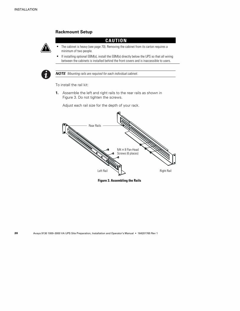
To install the rail kit:
1. Assemble the left and right rails to the rear rails as shown inFigure 3. Do not tighten the screws.
Adjust each rail size for the depth of your rack.
Rear Rails
Right RailLeft Rail
M4×8 Pan-HeadScrews (6 places)
Figure 3. Assembling the Rails
INSTALLATION
Avaya 9130 1000–3000 VA UPS Site Preparation, Installation and Operator’s Manual S 164201765 Rev 1 21
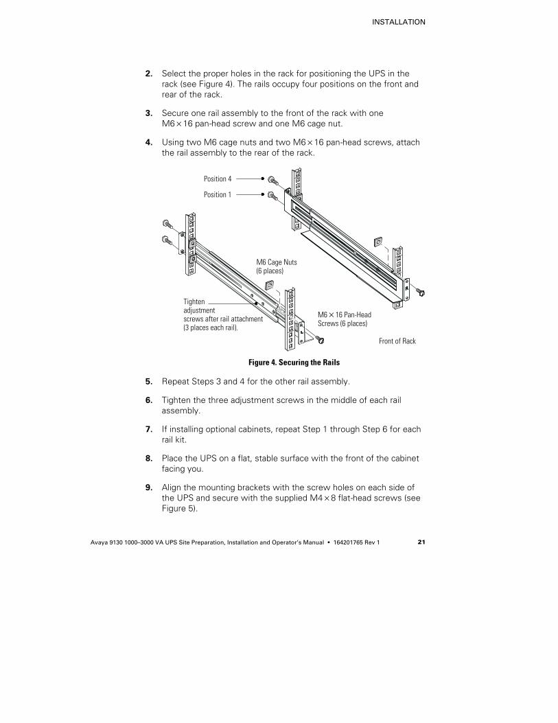
2. Select the proper holes in the rack for positioning the UPS in therack (see Figure 4). The rails occupy four positions on the front andrear of the rack.
3. Secure one rail assembly to the front of the rack with oneM6×16 pan-head screw and one M6 cage nut.
4. Using two M6 cage nuts and two M6×16 pan-head screws, attachthe rail assembly to the rear of the rack.
M6×16 Pan-HeadScrews (6 places)
Front of Rack
M6 Cage Nuts(6 places)
Tightenadjustmentscrews after rail attachment(3 places each rail).
Position 4
Position 1
Figure 4. Securing the Rails
5. Repeat Steps 3 and 4 for the other rail assembly.
6. Tighten the three adjustment screws in the middle of each railassembly.
7. If installing optional cabinets, repeat Step 1 through Step 6 for eachrail kit.
8. Place the UPS on a flat, stable surface with the front of the cabinetfacing you.
9. Align the mounting brackets with the screw holes on each side ofthe UPS and secure with the supplied M4×8 flat-head screws (seeFigure 5).
INSTALLATION
Avaya 9130 1000–3000 VA UPS Site Preparation, Installation and Operator’s Manual S 164201765 Rev 122
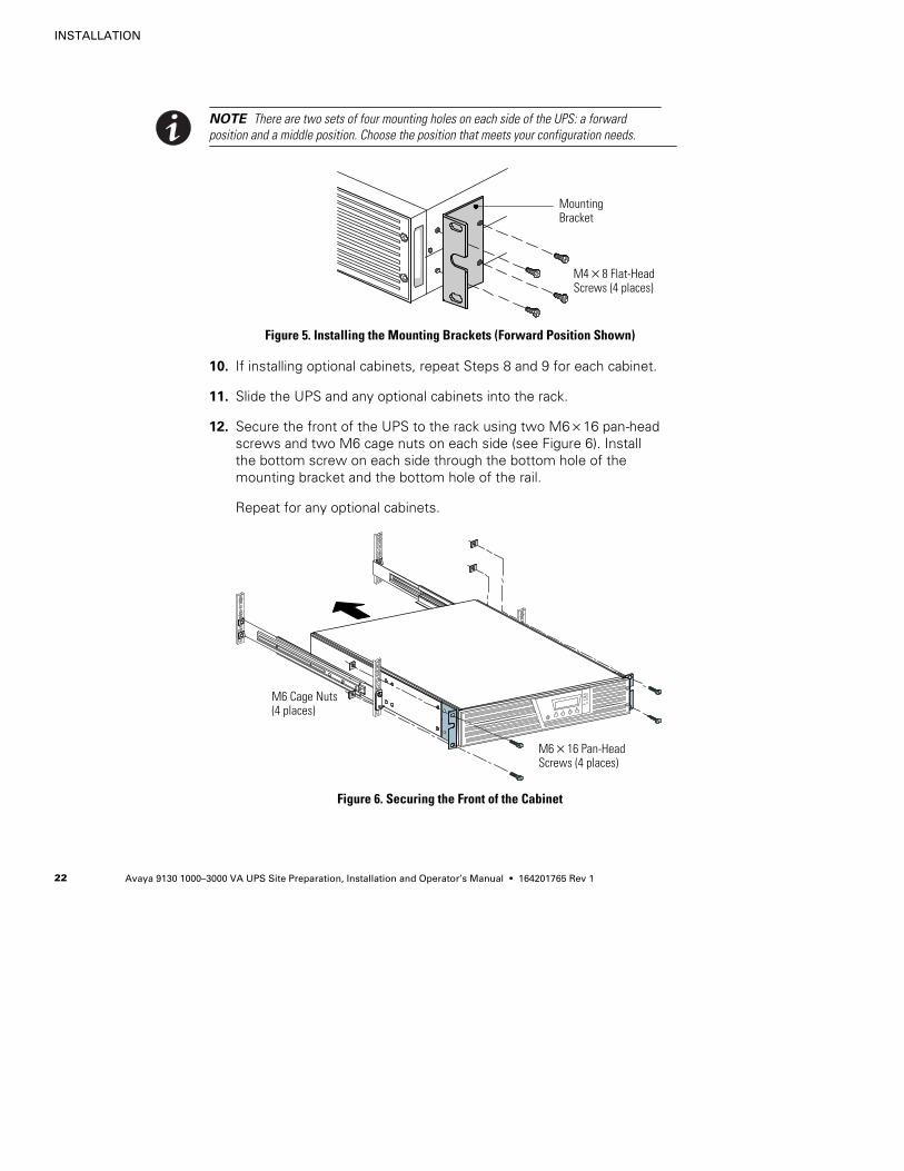
NOTE There are two sets of four mounting holes on each side of the UPS: a forwardposition and a middle position. Choose the position that meets your configuration needs.
MountingBracket
M4×8 Flat-HeadScrews (4 places)
Figure 5. Installing the Mounting Brackets (Forward Position Shown)
10. If installing optional cabinets, repeat Steps 8 and 9 for each cabinet.
11. Slide the UPS and any optional cabinets into the rack.
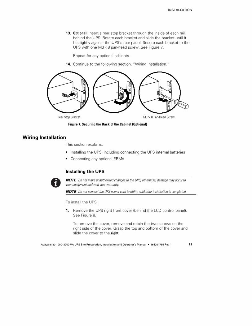
12. Secure the front of the UPS to the rack using two M6×16 pan-headscrews and two M6 cage nuts on each side (see Figure 6). Installthe bottom screw on each side through the bottom hole of themounting bracket and the bottom hole of the rail.
Repeat for any optional cabinets.
M6×16 Pan-HeadScrews (4 places)
M6 Cage Nuts(4 places)
Figure 6. Securing the Front of the Cabinet
INSTALLATION
Avaya 9130 1000–3000 VA UPS Site Preparation, Installation and Operator’s Manual S 164201765 Rev 1 23
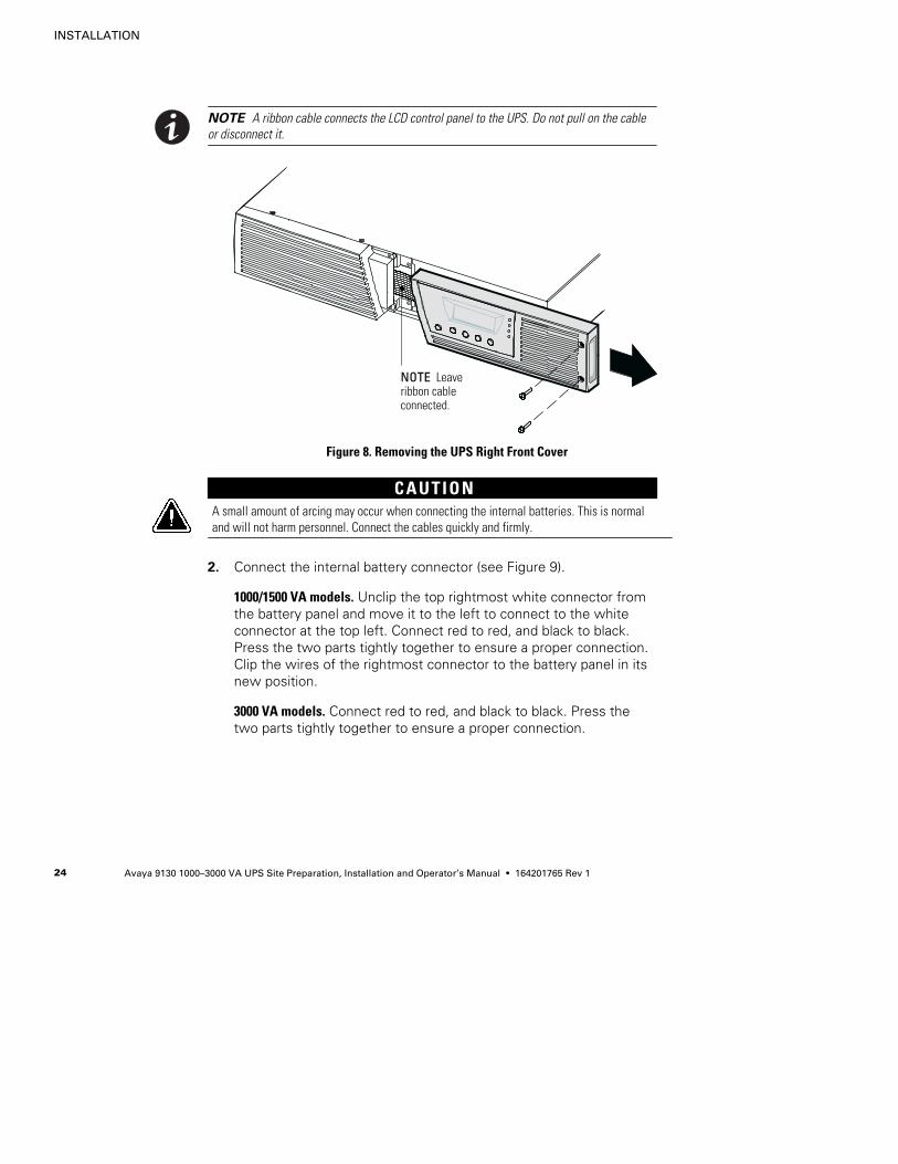
13. Optional. Insert a rear stop bracket through the inside of each railbehind the UPS. Rotate each bracket and slide the bracket until itfits tightly against the UPS’s rear panel. Secure each bracket to theUPS with one M3×8 pan-head screw. See Figure 7.
Repeat for any optional cabinets.
14. Continue to the following section, “Wiring Installation.”
Rear Stop Bracket M3×8 Pan-Head Screw
Figure 7. Securing the Back of the Cabinet (Optional)
Wiring Installation
This section explains:
S Installing the UPS, including connecting the UPS internal batteries
S Connecting any optional EBMs
Installing the UPS
NOTE Do not make unauthorized changes to the UPS; otherwise, damage may occur toyour equipment and void your warranty.
NOTE Do not connect the UPS power cord to utility until after installation is completed.
To install the UPS:
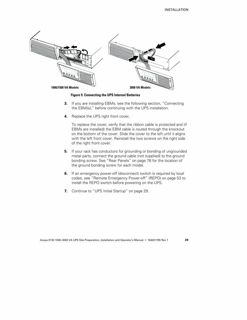
1. Remove the UPS right front cover (behind the LCD control panel).See Figure 8.
To remove the cover, remove and retain the two screws on theright side of the cover. Grasp the top and bottom of the cover andslide the cover to the right.
INSTALLATION
Avaya 9130 1000–3000 VA UPS Site Preparation, Installation and Operator’s Manual S 164201765 Rev 124
NOTE A ribbon cable connects the LCD control panel to the UPS. Do not pull on the cableor disconnect it.
NOTE Leaveribbon cableconnected.
Figure 8. Removing the UPS Right Front Cover
CAUTIONA small amount of arcing may occur when connecting the internal batteries. This is normaland will not harm personnel. Connect the cables quickly and firmly.
2. Connect the internal battery connector (see Figure 9).
1000/1500 VA models. Unclip the top rightmost white connector fromthe battery panel and move it to the left to connect to the whiteconnector at the top left. Connect red to red, and black to black.Press the two parts tightly together to ensure a proper connection.Clip the wires of the rightmost connector to the battery panel in itsnew position.
3000 VA models. Connect red to red, and black to black. Press thetwo parts tightly together to ensure a proper connection.
INSTALLATION
Avaya 9130 1000–3000 VA UPS Site Preparation, Installation and Operator’s Manual S 164201765 Rev 1 25
1000/1500 VA Models 3000 VA Models
Figure 9. Connecting the UPS Internal Batteries
3. If you are installing EBMs, see the following section, “Connectingthe EBM(s),” before continuing with the UPS installation.
4. Replace the UPS right front cover.
To replace the cover, verify that the ribbon cable is protected and (ifEBMs are installed) the EBM cable is routed through the knockouton the bottom of the cover. Slide the cover to the left until it alignswith the left front cover. Reinstall the two screws on the right sideof the right front cover.
5. If your rack has conductors for grounding or bonding of ungroundedmetal parts, connect the ground cable (not supplied) to the groundbonding screw. See “Rear Panels” on page 76 for the location ofthe ground bonding screw for each model.
6. If an emergency power-off (disconnect) switch is required by localcodes, see “Remote Emergency Power-off” (REPO) on page 53 toinstall the REPO switch before powering on the UPS.
7. Continue to “UPS Initial Startup” on page 29.
INSTALLATION
Avaya 9130 1000–3000 VA UPS Site Preparation, Installation and Operator’s Manual S 164201765 Rev 126
Connecting the EBM(s)
To install the optional EBM(s) for a UPS:
1. On the bottom of the UPS right front cover, remove the EBM cableknockout (see Figure 10).
NOTE Use care to protect the LCD control panel and the connected ribbon cable fromdamage.
esc
Knockout for EBM Cable
Figure 10. Removing the EBM Cable Knockout
2. Remove the front cover of each EBM (see Figure 11).
To remove the cover, remove and retain the two screws on theright side of the cover. Grasp the sides of the cover and slide thecover to the left and then away from the cabinet.
INSTALLATION
Avaya 9130 1000–3000 VA UPS Site Preparation, Installation and Operator’s Manual S 164201765 Rev 1 27
Bottom EBM Cable Knockout(underneath cover)
Top EBM Cable Knockout
EBM Cover Hook
Figure 11. Removing the EBM Front Cover
3. For the bottom (or only) EBM, remove the EBM cable knockout onthe top of the EBM front cover. See Figure 11 for the location of thetop EBM cable knockout.
4. If you are installing more than one EBM, for each additional EBMremove the EBM cable knockout on the top and bottom of the EBMfront cover. See Figure 11 for the location of the EBM cableknockouts.
INSTALLATION
Avaya 9130 1000–3000 VA UPS Site Preparation, Installation and Operator’s Manual S 164201765 Rev 128
CAUTIONA small amount of arcing may occur when connecting an EBM to the UPS. This is normal andwill not harm personnel. Insert the EBM cable into the UPS battery connector quickly andfirmly.
5. Plug the EBM cable(s) into the battery connector(s) as shown inFigure 12. Up to four EBMs may be connected to the UPS.
1000/1500 VA models. Unclip the EBM connector on the UPS batterypanel and connect it to the EBM connector on the EBM. Press thetwo parts tightly together to ensure a proper connection.
3000 VA models. Connect red to red, black to black, and green togreen. Press the two parts tightly together to ensure a properconnection.
All models. To connect a second EBM, unclip the EBM connector onthe first EBM and pull gently to extend the wiring to the EBMconnector on the second EBM. Repeat for any additional EBMs.
6. Verify that the EBM connections are tight and that adequate bendradius and strain relief exist for each cable.
1000/1500 VA Models 3000 VA Models
Figure 12. Typical EBM Installation
INSTALLATION
Avaya 9130 1000–3000 VA UPS Site Preparation, Installation and Operator’s Manual S 164201765 Rev 1 29
7. Replace the EBM front cover.
To replace the cover, verify that the EBM cables are routed throughthe EBM cover knockouts, then slide the cover from the left to theright until it connects with the cover hook near the left side of theEBM cabinet. Reinstall the two screws on the right side of the frontcover. For reference, see Figure 11 on page 27.
Repeat for each additional EBM.
8. Verify that all wiring connecting the UPS and EBM(s) is installedbehind the front covers and is inaccessible to users.
9. Return to Step 4 on page 25 to continue the UPS installation.
UPS Initial Startup
To start up the UPS:
NOTE Verify that the total equipment ratings do not exceed the UPS capacity to prevent anoverload alarm.
1. Verify that the internal batteries are connected. See “Installing theUPS” on page 23.
2. If optional EBMs are installed, verify that the EBMs are connectedto the UPS. See “Connecting the EBM(s)” on page 26.
3. Plug the equipment to be protected into the UPS, but do not turnon the protected equipment.
4. Make any necessary provisions for cord retention and strain relief.
5. Models without an attached power cord. Plug the detachable UPSpower cord into the input connector on the UPS rear panel.
6. Plug the UPS power cord into a power outlet.
The UPS front panel display illuminates and shows a status of “UPSinitializing...”
7. Verify that the UPS transfers to Standby mode (”UPS on standby”).
8. Press the button on the UPS front panel for at least one second.
The UPS front panel display changes status to “UPS starting...”
INSTALLATION
Avaya 9130 1000–3000 VA UPS Site Preparation, Installation and Operator’s Manual S 164201765 Rev 130
9. Check the UPS front panel display for active alarms or notices.Resolve any active alarms before continuing. See“Troubleshooting” on page 79.
If the indicator is on, do not proceed until all alarms are clear.Check the UPS status from the front panel to view the activealarms. Correct the alarms and restart if necessary.
10. Verify that the indicator illuminates solid, indicating that theUPS is operating normally and any loads are powered.
The UPS should be in Normal mode.
11. Press the ESC button until the start screen appears.
12. If optional EBMs are installed, see “Configuring the UPS for EBMs”on page 46 to set the number of installed EBMs.
13. To change any other factory-set defaults, see “Operation” onpage 33.
NOTE Avaya recommends setting the date and time.
NOTE At initial startup, the UPS sets system frequency according to input line frequency(input frequency auto-sensing is enabled by default). After initial startup, auto-sensing isdisabled until manually re-enabled by output frequency setting.
NOTE At initial startup, input voltage auto-sensing is disabled by default. When manuallyenabled by output voltage setting, at the next AC startup the UPS sets output voltageaccording to input line voltage. After the subsequent startup, auto-sensing is disabled untilmanually re-enabled by output voltage setting.
14. If you installed an optional REPO, test the REPO function:
Activate the external REPO switch. Verify the status change on theUPS display.
Deactivate the external REPO switch and restart the UPS.
INSTALLATION
Avaya 9130 1000–3000 VA UPS Site Preparation, Installation and Operator’s Manual S 164201765 Rev 1 31
NOTE The internal batteries charge to 90% capacity in less than 3 hours. However, Avayarecommends that the batteries charge for 48 hours after installation or long-term storage. Ifoptional EBMs are installed, see the recharge times listed in Table 19 on page 75.
15. Keep your UPS firmware updated. See “Updating the UPSFirmware” on page 67.
16. If you are installing power management software, refer to theConnectUPS Web/SNMP Card Quick Start Instructions andConnectUPS Web/SNMP Card User’s Guide on the Software SuiteCD for configuration instructions.

INSTALLATION
Avaya 9130 1000–3000 VA UPS Site Preparation, Installation and Operator’s Manual S 164201765 Rev 132
Avaya 9130 1000–3000 VA UPS Site Preparation, Installation and Operator’s Manual S 164201765 Rev 1 33
Chapter 4 Operation
This chapter contains information on how to use the Avaya 9130,including front panel operation, operating modes, UPS startup andshutdown, transferring the UPS between modes, retrieving the EventLog, setting the power strategy, and configuring bypass settings, loadsegments, and battery settings.
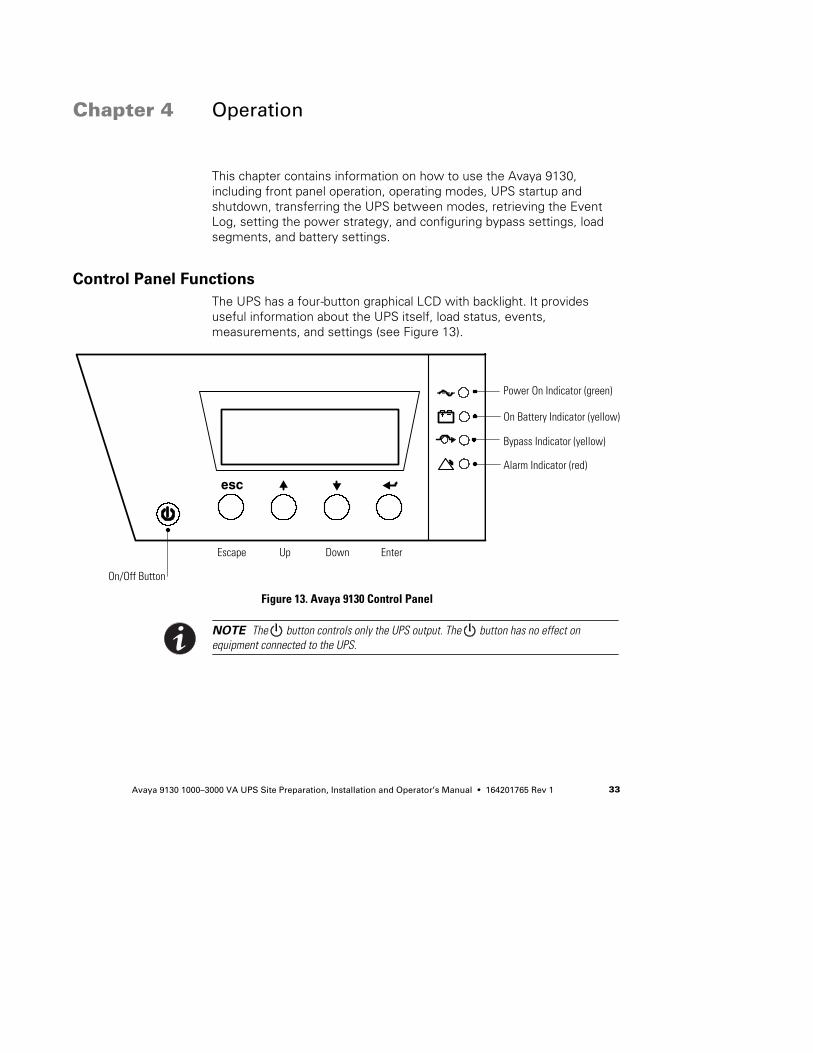
Control Panel Functions
The UPS has a four-button graphical LCD with backlight. It providesuseful information about the UPS itself, load status, events,measurements, and settings (see Figure 13).
Power On Indicator (green)
On Battery Indicator (yellow)
Bypass Indicator (yellow)
Alarm Indicator (red)
On/Off Button
Escape Up Down Enter
esc
Figure 13. Avaya 9130 Control Panel
NOTE The button controls only the UPS output. The button has no effect onequipment connected to the UPS.
OPERATION
Avaya 9130 1000–3000 VA UPS Site Preparation, Installation and Operator’s Manual S 164201765 Rev 134
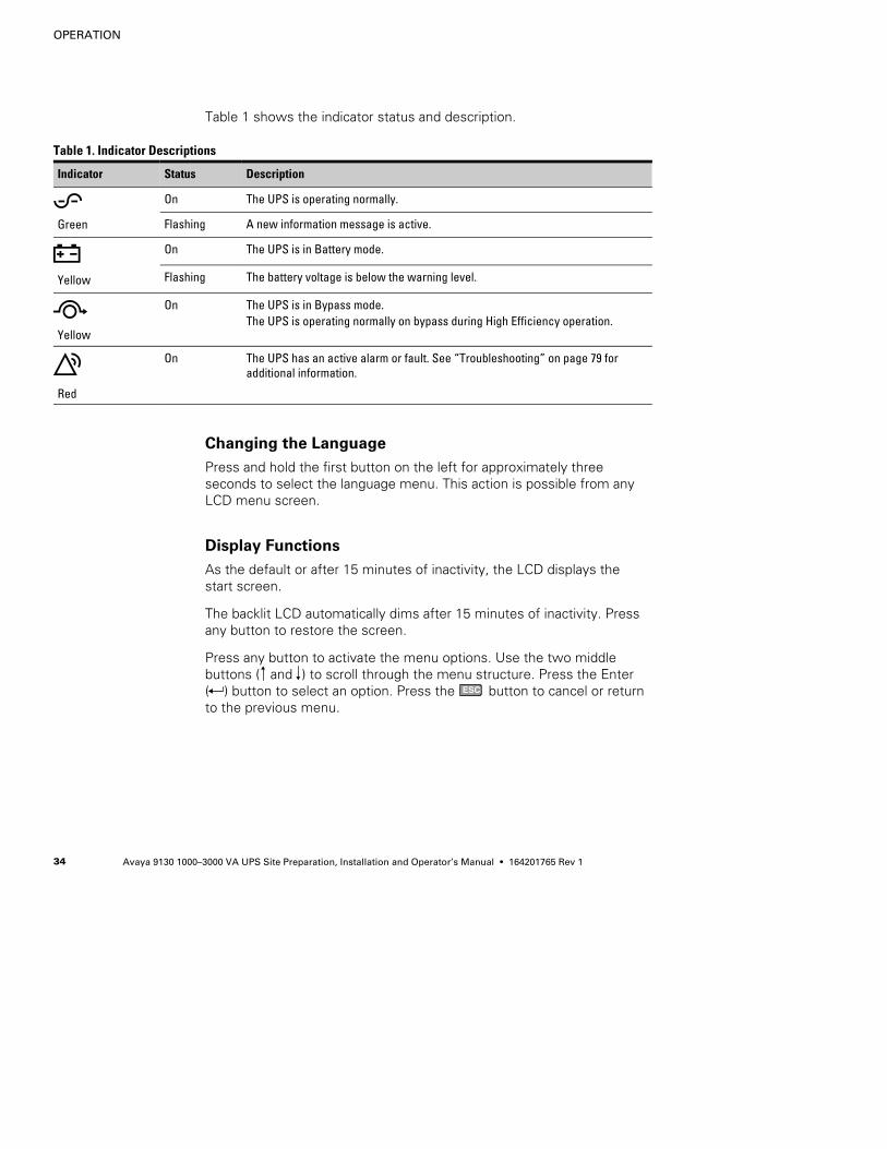
Table 1 shows the indicator status and description.
Table 1. Indicator Descriptions
Indicator Status Description
Green
On The UPS is operating normally.
Flashing A new information message is active.
Yellow
On The UPS is in Battery mode.
Flashing The battery voltage is below the warning level.
Yellow
On The UPS is in Bypass mode.The UPS is operating normally on bypass during High Efficiency operation.
Red
On The UPS has an active alarm or fault. See “Troubleshooting” on page 79 foradditional information.
Changing the Language
Press and hold the first button on the left for approximately threeseconds to select the language menu. This action is possible from anyLCD menu screen.
Display Functions
As the default or after 15 minutes of inactivity, the LCD displays thestart screen.
The backlit LCD automatically dims after 15 minutes of inactivity. Pressany button to restore the screen.
Press any button to activate the menu options. Use the two middlebuttons ( and ) to scroll through the menu structure. Press the Enter( ) button to select an option. Press the ESC button to cancel or returnto the previous menu.
OPERATION
Avaya 9130 1000–3000 VA UPS Site Preparation, Installation and Operator’s Manual S 164201765 Rev 1 35
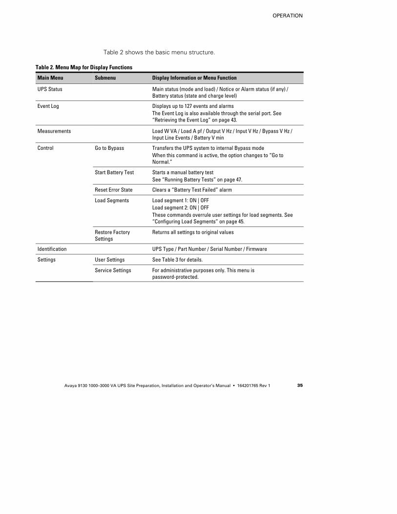
Table 2 shows the basic menu structure.
Table 2. Menu Map for Display Functions
Main Menu Submenu Display Information or Menu Function
UPS Status Main status (mode and load) / Notice or Alarm status (if any) /Battery status (state and charge level)
Event Log Displays up to 127 events and alarmsThe Event Log is also available through the serial port. See“Retrieving the Event Log” on page 43.
Measurements Load W VA / Load A pf / Output V Hz / Input V Hz / Bypass V Hz /Input Line Events / Battery V min
Control Go to Bypass Transfers the UPS system to internal Bypass modeWhen this command is active, the option changes to “Go toNormal.”
Start Battery Test Starts a manual battery testSee “Running Battery Tests” on page 47.
Reset Error State Clears a “Battery Test Failed” alarm
Load Segments Load segment 1: ON | OFFLoad segment 2: ON | OFFThese commands overrule user settings for load segments. See“Configuring Load Segments” on page 45.
Restore FactorySettings
Returns all settings to original values
Identification UPS Type / Part Number / Serial Number / Firmware
Settings User Settings See Table 3 for details.
Service Settings For administrative purposes only. This menu ispassword-protected.
OPERATION
Avaya 9130 1000–3000 VA UPS Site Preparation, Installation and Operator’s Manual S 164201765 Rev 136
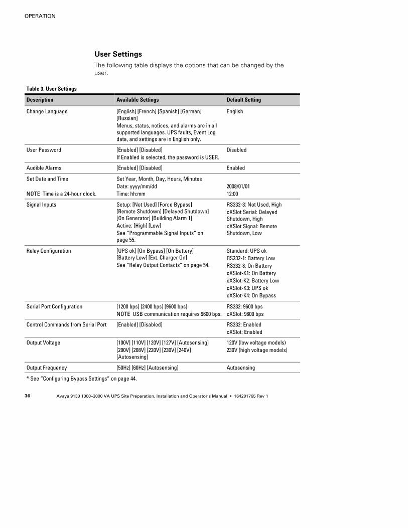
User Settings
The following table displays the options that can be changed by theuser.
Table 3. User Settings
Description Available Settings Default Setting
Change Language [English] [French] [Spanish] [German][Russian]Menus, status, notices, and alarms are in allsupported languages. UPS faults, Event Logdata, and settings are in English only.
English
User Password [Enabled] [Disabled]If Enabled is selected, the password is USER.
Disabled
Audible Alarms [Enabled] [Disabled] Enabled
Set Date and Time
NOTE Time is a 24-hour clock.
Set Year, Month, Day, Hours, MinutesDate: yyyy/mm/ddTime: hh:mm
2008/01/0112:00
Signal Inputs Setup: [Not Used] [Force Bypass][Remote Shutdown] [Delayed Shutdown][On Generator] [Building Alarm 1]Active: [High] [Low]See “Programmable Signal Inputs” onpage 55.
RS232-3: Not Used, HighcXSlot Serial: DelayedShutdown, HighcXSlot Signal: RemoteShutdown, Low
Relay Configuration [UPS ok] [On Bypass] [On Battery][Battery Low] [Ext. Charger On]See “Relay Output Contacts” on page 54.
Standard: UPS okRS232-1: Battery LowRS232-8: On BatterycXSlot-K1: On BatterycXSlot-K2: Battery LowcXSlot-K3: UPS okcXSlot-K4: On Bypass
Serial Port Configuration [1200 bps] [2400 bps] [9600 bps]NOTE USB communication requires 9600 bps.
RS232: 9600 bpscXSlot: 9600 bps
Control Commands from Serial Port [Enabled] [Disabled] RS232: EnabledcXSlot: Enabled
Output Voltage [100V] [110V] [120V] [127V] [Autosensing][200V] [208V] [220V] [230V] [240V][Autosensing]
120V (low voltage models)230V (high voltage models)
Output Frequency [50Hz] [60Hz] [Autosensing] Autosensing
* See “Configuring Bypass Settings” on page 44.
OPERATION
Avaya 9130 1000–3000 VA UPS Site Preparation, Installation and Operator’s Manual S 164201765 Rev 1 37
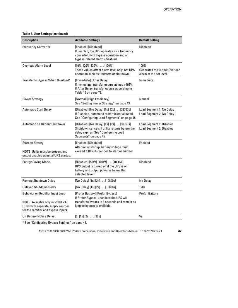
Table 3. User Settings (continued)
Default SettingAvailable SettingsDescription
Frequency Converter [Enabled] [Disabled]If Enabled, the UPS operates as a frequencyconverter, with bypass operation and allbypass-related alarms disabled.
Disabled
Overload Alarm Level [10%] [20%] [30%] . . . [100%]These values affect alarm level only, not UPSoperation such as transfers or shutdown.
100%Generates the Output Overloadalarm at the set level.
Transfer to Bypass When Overload* [Immediate] [After Delay]If Immediate, transfer occurs at load >102%.If After Delay, transfer occurs according toTable 15 on page 72.
Immediate
Power Strategy [Normal] [High Efficiency]See “Setting Power Strategy” on page 43.
Normal
Automatic Start Delay [Disabled] [No Delay] [1s] [2s] . . . [32767s]If Disabled, automatic restart is not allowed.See “Configuring Load Segments” on page 45.
Load Segment 1: No DelayLoad Segment 2: No Delay
Automatic on Battery Shutdown [Disabled] [No Delay] [1s] [2s] . . . [32767s]Shutdown cancels if utility returns before thedelay expires. See “Configuring LoadSegments” on page 45.
Load Segment 1: DisabledLoad Segment 2: Disabled
Start on Battery
NOTE Utility must be present andoutput enabled at initial UPS startup.
[Enabled] [Disabled]After initial startup, battery voltage mustexceed 2.10 volts per cell to start on battery.
Enabled
Energy Saving Mode [Disabled] [50W] [100W] . . . [1000W]UPS output is turned off if the UPS is onbattery and output power is below theselected level.
Disabled
Remote Shutdown Delay [No Delay] [1s] [2s] . . . [10800s] No Delay
Delayed Shutdown Delay [No Delay] [1s] [2s] . . . [10800s] 120s
Behavior on Rectifier Input Loss
NOTE Available only in >3000 VAUPSs with separate supply sourcesfor the rectifier and bypass inputs.
[Prefer Battery] [Prefer Bypass]If Prefer Bypass, upon loss the UPS willtransfer to bypass in 3 seconds and remain aslong as bypass is available.
Prefer Battery
On Battery Notice Delay [0] [1s] [2s] . . . [99s] 5s
* See “Configuring Bypass Settings” on page 44.
OPERATION
Avaya 9130 1000–3000 VA UPS Site Preparation, Installation and Operator’s Manual S 164201765 Rev 138
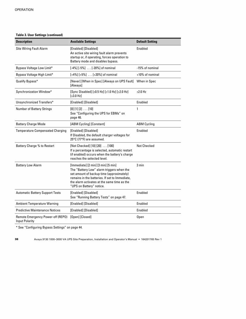
Table 3. User Settings (continued)
Default SettingAvailable SettingsDescription
Site Wiring Fault Alarm [Enabled] [Disabled]An active site wiring fault alarm preventsstartup or, if operating, forces operation toBattery mode and disables bypass.
Enabled
Bypass Voltage Low Limit* [-4%] [-5%] . . . [-20%] of nominal -15% of nominal
Bypass Voltage High Limit* [+4%] [+5%] . . . [+20%] of nominal +10% of nominal
Qualify Bypass* [Never] [When in Spec] [Always on UPS Fault][Always]
When in Spec
Synchronization Window* [Sync Disabled] [±0.5 Hz] [±1.0 Hz] [±2.0 Hz][±3.0 Hz]
±2.0 Hz
Unsynchronized Transfers* [Enabled] [Disabled] Enabled
Number of Battery Strings [0] [1] [2] . . . [10]See “Configuring the UPS for EBMs” onpage 46.
1
Battery Charge Mode [ABM Cycling] [Constant] ABM Cycling
Temperature Compensated Charging [Enabled] [Disabled]If Disabled, the default charger voltages for25°C (77°F) are assumed.
Enabled
Battery Charge % to Restart [Not Checked] [10] [20] . . . [100]If a percentage is selected, automatic restart(if enabled) occurs when the battery’s chargereaches the selected level.
Not Checked
Battery Low Alarm [Immediate] [2 min] [3 min] [5 min]The “Battery Low” alarm triggers when theset amount of backup time (approximately)remains in the batteries. If set to Immediate,the alarm activates at the same time as the“UPS on Battery” notice.
3 min
Automatic Battery Support Tests [Enabled] [Disabled]See “Running Battery Tests” on page 47.
Enabled
Ambient Temperature Warning [Enabled] [Disabled] Enabled
Predictive Maintenance Notices [Enabled] [Disabled] Enabled
Remote Emergency Power-off (REPO)Input Polarity
[Open] [Closed] Open
* See “Configuring Bypass Settings” on page 44.
OPERATION
Avaya 9130 1000–3000 VA UPS Site Preparation, Installation and Operator’s Manual S 164201765 Rev 1 39
Operating Modes
The Avaya 9130 front panel indicates the UPS status through the UPSindicators (see Figure 13 on page 33).
Normal Mode
During Normal mode, the indicator illuminates solid and the UPS ispowered from the utility. The UPS monitors and charges the batteries asneeded and provides filtered power protection to your equipment.
The UPS may at times silently implement a High Alert mode, usuallywhen incoming utility conditions are unfavorable. In High Alert mode,the UPS disables the battery support test to ensure maximum capacityfrom the batteries if needed. The UPS will remain in High Alert for24 hours or until changed by a Power Strategy command beforereturning to its previous mode.
Optional High Efficiency and Energy Saving settings minimize heatcontribution to the rack environment. See “User Settings” on page 36.
Battery Mode
When the UPS is operating during a power outage, the alarm beepsonce every five seconds and the indicator illuminates solid.
When the utility power returns, the UPS transfers to Normal modeoperation while the battery recharges.
If battery capacity becomes low while in Battery mode, the indicatorflashes slowly and the audible alarm beeps once every second. If the“Battery Low” alarm is set, the indicator also illuminates solid. Thiswarning is approximate, and the actual time to shutdown may varysignificantly.
NOTE Depending on the UPS load and the number of Extended Battery Modules (EBMs)connected, the “Battery Low” warning may occur before the batteries reach 25% capacity.See Table 18 on page 75 for estimated runtimes.
When utility power is restored after the UPS shuts down, the UPSautomatically restarts.
OPERATION
Avaya 9130 1000–3000 VA UPS Site Preparation, Installation and Operator’s Manual S 164201765 Rev 140
Bypass Mode
In the event of a UPS overload or internal failure, the UPS transfers yourequipment to utility power. Battery mode is not available and yourequipment is not protected; however, the utility power continues to bepassively filtered by the UPS. The indicator illuminates.
The UPS remains in Bypass mode for at least 5 seconds (if the bypasssource remains acceptable). If three transfers to Bypass occur within10 minutes for any reason other than user command, the UPS locks inBypass for 1 hour or until any control button is pressed.
The UPS transfers to Bypass mode when:
S The user activates Bypass mode through the front panel.
S The UPS detects an internal failure.
S The UPS has an overtemperature condition.
S The UPS has an overload condition listed in Table 15 on page 72.
NOTE The UPS shuts down after a specified delay for overload conditions listed inTable 15 on page 72. The UPS remains on to alarm the fault.
Standby Mode
When the UPS is turned off and remains plugged into a power outlet,the UPS is in Standby mode. The indicator is off, indicating thatpower is not available to your equipment. The battery recharges whennecessary, and the communication bay is powered.
If utility fails and output turns off due to drained batteries or UPS internalfailure, the UPS alarms in Standby mode and powers the communicationbay for 1 hour 30 minutes or until battery voltage drops below 1.75 voltsper cell (whichever occurs first).
If utility fails while the UPS is in Standby mode, the logic power supplyturns off in approximately 10 seconds.
If the UPS is waiting on commands and utility fails, unit and logic powerturn off in approximately 30 seconds.
OPERATION
Avaya 9130 1000–3000 VA UPS Site Preparation, Installation and Operator’s Manual S 164201765 Rev 1 41
UPS Startup and Shutdown
To start up or shut down the UPS, see:
S “Starting the UPS” on page 41
S “Starting the UPS on Battery” on page 42
S “UPS Shutdown” on page 42
Starting the UPS
To start the UPS:
1. Verify that the UPS power cord is plugged in.
2. Switch on utility power where the UPS is connected.
The UPS front panel display illuminates and shows a status of “UPSinitializing . . .”
3. Verify that the UPS transfers to Standby mode (”UPS on standby”).
4. Press the button on the UPS front panel for at least one second.
The UPS front panel display changes status to “UPS starting . . .”
5. Check the UPS front panel display for active alarms or notices.Resolve any active alarms before continuing. See“Troubleshooting” on page 79.
If the indicator is on, do not proceed until all alarms are clear.Check the UPS status from the front panel to view the activealarms. Correct the alarms and restart if necessary.
6. Verify that the indicator illuminates solid, indicating that theUPS is operating normally and any loads are powered.
The UPS should be in Normal mode.
7. Press the ESC button until the start screen appears.
OPERATION
Avaya 9130 1000–3000 VA UPS Site Preparation, Installation and Operator’s Manual S 164201765 Rev 142
Starting the UPS on Battery
NOTE Before using this feature, the UPS must have been powered by utility power withoutput enabled at least once.
NOTE Battery start can be disabled. See the “Start on Battery” setting in “User Settings”on page 36.
To start the UPS on battery:
1. Press the button on the UPS front panel until the UPS front paneldisplay illuminates and shows a status of “UPS starting . . .”
The UPS cycles through Standby mode to Battery mode. Theindicator illuminates solid. The UPS supplies power to your
equipment.
2. Check the UPS front panel display for active alarms or noticesbesides the “UPS on Battery” notice and notices that indicatemissing utility power. Resolve any active alarms before continuing.See “Troubleshooting” on page 79.
Check the UPS status from the front panel to view the activealarms. Correct the alarms and restart if necessary.
3. Press the ESC button until the start screen appears.
UPS Shutdown
To shut down the UPS:
1. Press the button on the front panel for three seconds.
The UPS starts to beep and shows a status of “UPS offpending . . .” The UPS then transfers to Standby mode, and the
indicator turns off.
NOTE Releasing the button before three seconds returns the UPS to its originaloperating mode.
2. Switch off utility power where the UPS is connected.
OPERATION
Avaya 9130 1000–3000 VA UPS Site Preparation, Installation and Operator’s Manual S 164201765 Rev 1 43
Transferring the UPS Between Modes
From Normal to Bypass Mode. Press any button to activate the menuoptions, then select CONTROL and GO TO BYPASS.
From Bypass to Normal Mode. Press any button to activate the menuoptions, then select CONTROL and GO TO NORMAL.
Retrieving the Event Log
To retrieve the Event Log through the display:
1. Press any button to activate the menu options, then selectEVENT LOG.
2. Scroll through the listed events.
To retrieve the Event Log through the serial port:
1. From the communication device connected to the serial port, sendone of the following command sequences: ESC-L (ASCII characters27 and 76) or ESC-I (ASCII characters 27 and 108).
The UPS returns a header containing the UPS identification (UPStype, part number, and serial number), firmware version, and thecurrent date and time, followed by the event history.
2. Use the connected communication device to view or print theinformation. The report is delivered in ASCII format.
Setting Power Strategy
On the High Efficiency setting, the UPS operates normally on Bypass,transfers to inverter in less than 10 ms when utility fails, and transfersback to Bypass in 1 minute after utility returns. The indicatorilluminates when the UPS transfers to Bypass.
NOTE High Efficiency operation is available after one minute of stable power.
To set the power strategy:
1. Press any button to activate the menu options, then selectSETTINGS, USER SETTINGS, and POWER STRATEGY.
2. Select HIGH EFFICIENCY or NORMAL, and ENTER to confirm.
OPERATION
Avaya 9130 1000–3000 VA UPS Site Preparation, Installation and Operator’s Manual S 164201765 Rev 144
Configuring Bypass Settings
The following settings are available for configuring Bypass operation.
Transfer to Bypass When Overload. The default forces a transfer to Bypasswhen any overload condition occurs. You can configure the setting for adelayed transfer, with the amount of delay determined by the amount ofoverload, as shown in Table 15 on page 72.
Bypass Voltage Low Limit. The default disables a transfer to Bypass if themeasured bypass voltage level is below the nominal output voltageminus 15%. You can configure the setting for another percentage ofnominal. This setting can be overruled by the “Qualify Bypass” setting.
Bypass Voltage High Limit. The default disables a transfer to Bypass if themeasured bypass voltage level is above the nominal output voltageplus 10%. You can configure the setting for another percentage ofnominal. This setting can be overruled by the “Qualify Bypass” setting.
Qualify Bypass. The default allows a transfer to Bypass only when Bypassis within the following specifications:
S Bypass voltage is between the “Bypass Voltage Low Limit” and“Bypass Voltage High Limit” settings.
S Bypass frequency is within nominal frequency ±5 Hz.
S The inverter is synchronized with Bypass when the “UnsynchronizedTransfers” setting is disabled.
You can prohibit Bypass (”Never”) or always allow Bypass with nospecification checking (”Always”). For “Always on UPS Fault,” transferto Bypass is always made on UPS fault; otherwise, operation proceedsas with the default setting.
Synchronization Window. The UPS tries to synchronize with Bypass whenthe Bypass frequency is less than the value set for the “SynchronizationWindow” setting. When the Bypass frequency is more than the setvalue, the UPS goes to nominal frequency. On Bypass thesynchronization window is ±5 Hz. If synchronization is disabled (”SyncDisabled”), the UPS will synchronize only when operating on Bypass.
Unsynchronized Transfers. The default allows an unsynchronized transferto Bypass. You can configure the setting to not allow such transfers.This setting can be overruled by the “Qualify Bypass” setting.
OPERATION
Avaya 9130 1000–3000 VA UPS Site Preparation, Installation and Operator’s Manual S 164201765 Rev 1 45
Configuring Load Segments
Load segments are sets of receptacles that can be controlled by powermanagement software or through the display, providing an orderlyshutdown and startup of your equipment. For example, during a poweroutage, you can keep key pieces of equipment running while you turnoff other equipment. This feature allows you to save battery power.
Each UPS has two configurable load segments:
S Load Segment 1: Upper outlets and higher rated outlets if available.
S Load Segment 2: Lower outlets
See “Rear Panels” on page 76 for load segments for each UPS model.
To control the load segments with power management software, seeyour power management software manual for details (refer to theSoftware Suite CD or www.powerware.com/avaya for the latestinformation).
To control the load segments through the display:
1. Press any button to activate the menu options, then selectCONTROL and LOAD SEGMENTS.
2. Set the desired load segment ON or OFF, and ENTER to confirm.
3. Set the other load segment if applicable.
To set the restart and shutdown delay times for each load segment:
1. Press any button to activate the menu options, then selectSETTINGS, USER SETTINGS and AUTOMATIC START DELAY.
2. Set the restart delay for one load segment, and ENTER to confirm.
3. Set the other load segment if applicable.
4. Select AUTOMATIC ON BATTERY SHUTDOWN.
5. Set the shutdown delay for one load segment, and ENTER toconfirm.
6. Set the other load segment if applicable.
NOTE Load segment On/Off commands issued through the Control menu overrule the usersettings for load segments.
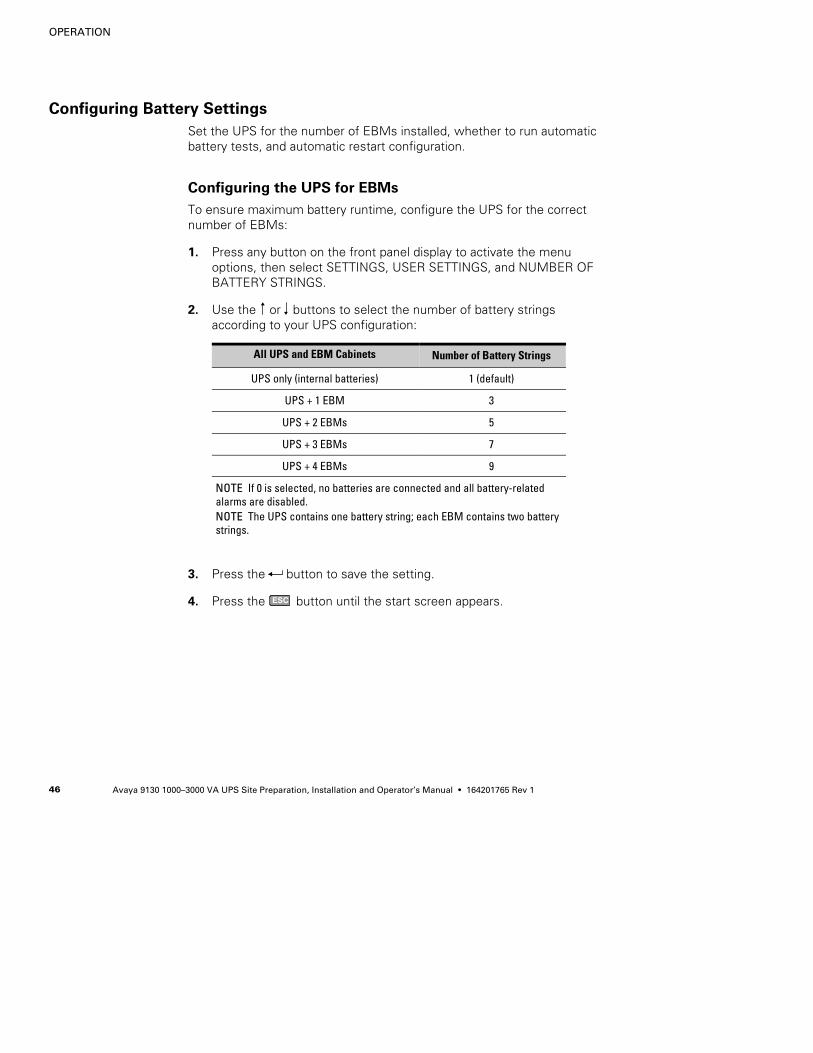
OPERATION
Avaya 9130 1000–3000 VA UPS Site Preparation, Installation and Operator’s Manual S 164201765 Rev 146
Configuring Battery Settings
Set the UPS for the number of EBMs installed, whether to run automaticbattery tests, and automatic restart configuration.
Configuring the UPS for EBMs
To ensure maximum battery runtime, configure the UPS for the correctnumber of EBMs:
1. Press any button on the front panel display to activate the menuoptions, then select SETTINGS, USER SETTINGS, and NUMBER OFBATTERY STRINGS.
2. Use the or buttons to select the number of battery stringsaccording to your UPS configuration:
All UPS and EBM Cabinets Number of Battery Strings
UPS only (internal batteries) 1 (default)
UPS + 1 EBM 3
UPS + 2 EBMs 5
UPS + 3 EBMs 7
UPS + 4 EBMs 9
NOTE If 0 is selected, no batteries are connected and all battery-relatedalarms are disabled.NOTE The UPS contains one battery string; each EBM contains two batterystrings.
3. Press the button to save the setting.
4. Press the ESC button until the start screen appears.
OPERATION
Avaya 9130 1000–3000 VA UPS Site Preparation, Installation and Operator’s Manual S 164201765 Rev 1 47
Running Battery Tests
Automatic battery tests run approximately every 30 days, unlessdisabled. During the test, the UPS transfers to Battery mode anddischarges the batteries for 25 seconds under the existing load.
NOTE The “UPS on Battery” notice and the “Battery Low” alarm do not activate during abattery test.
For an automatic battery test to run:
S The “Automatic Battery Support Tests” setting must be enabled.
S The UPS must be in Normal mode, with no active alarms.
S The batteries must be fully charged.
S The bypass voltage must be acceptable.
S No manual battery test was initiated previously in the same chargingcycle.
For a manual battery test to run:
S The UPS must be in Normal mode, with no active alarms.
S The bypass voltage must be acceptable.
To run a manual battery test:
1. Press any button to activate the menu options.
2. Select CONTROL then START BATTERY TEST.
During the battery test, the UPS transfers to Battery mode anddischarges the batteries for 25 seconds. The front panel displays“Battery test running” and the percentage of the test completed.
During the battery test, the UPS monitors the battery voltage constantly.If the expected total discharge time is greater than 15 minutes, thebattery voltage should remain above 1.83 volts per cell (VPC) during thetest. If the expected total discharge time is less than or equal to15 minutes, the threshold is 1.81 VPC.
To pass the battery test, the battery voltage must remain above thethreshold value during discharge.
If the battery voltage drops below the threshold, the UPS returns toNormal mode and the front panel displays “Battery Test Failed.”
OPERATION
Avaya 9130 1000–3000 VA UPS Site Preparation, Installation and Operator’s Manual S 164201765 Rev 148
You can clear the alarm by selecting CONTROL and RESET ERRORSTATE from the front panel display. The alarm clears automaticallyanytime the UPS is restarted, when a battery disconnection is detected,or if another battery test is initiated and passed.
Configuring Automatic Restart
The UPS automatically restarts if utility returns after the output was shutoff due to exhausted batteries, a shutdown input signal, or automaticshutdown command.
You can set the load segment for the amount of time to delay the restartonce utility returns, using the “Automatic Start Delay” setting. You canalso configure UPS restart to depend on the battery charge level, usingthe “Battery Charge % to Restart” setting.
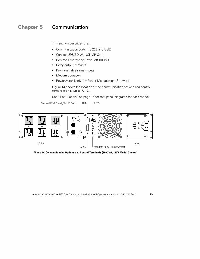
Avaya 9130 1000–3000 VA UPS Site Preparation, Installation and Operator’s Manual S 164201765 Rev 1 49
Chapter 5 Communication
This section describes the:
S Communication ports (RS-232 and USB)
S ConnectUPS-BD Web/SNMP Card
S Remote Emergency Power-off (REPO)
S Relay output contacts
S Programmable signal inputs
S Modem operation
S Powerware® LanSafe® Power Management Software
Figure 14 shows the location of the communication options and controlterminals on a typical UPS.
See “Rear Panels” on page 76 for rear panel diagrams for each model.
ConnectUPS-BD Web/SNMP Card USB REPO
RS-232 Standard Relay Output ContactOutput Input
Figure 14. Communication Options and Control Terminals (1000 VA, 120V Model Shown)
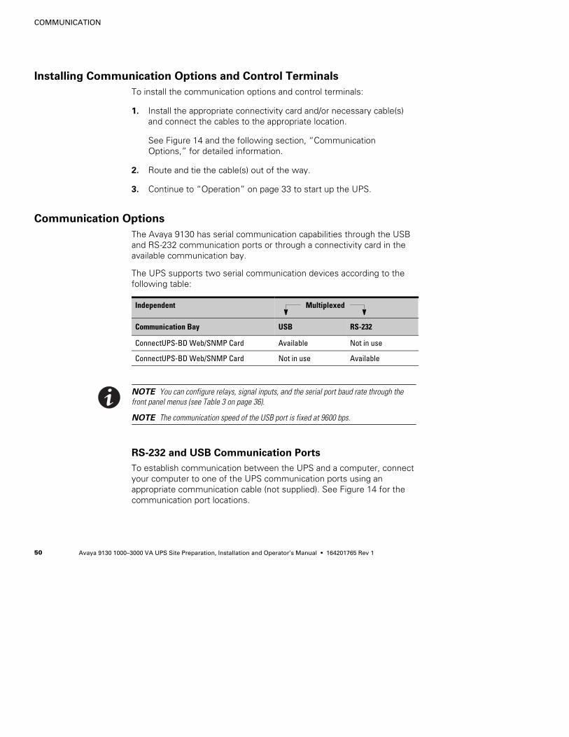
COMMUNICATION
Avaya 9130 1000–3000 VA UPS Site Preparation, Installation and Operator’s Manual S 164201765 Rev 150
Installing Communication Options and Control Terminals
To install the communication options and control terminals:
1. Install the appropriate connectivity card and/or necessary cable(s)and connect the cables to the appropriate location.
See Figure 14 and the following section, “CommunicationOptions,” for detailed information.
2. Route and tie the cable(s) out of the way.
3. Continue to “Operation” on page 33 to start up the UPS.
Communication Options
The Avaya 9130 has serial communication capabilities through the USBand RS-232 communication ports or through a connectivity card in theavailable communication bay.
The UPS supports two serial communication devices according to thefollowing table:
Independent Multiplexed
Communication Bay USB RS-232
ConnectUPS-BD Web/SNMP Card Available Not in use
ConnectUPS-BD Web/SNMP Card Not in use Available
NOTE You can configure relays, signal inputs, and the serial port baud rate through thefront panel menus (see Table 3 on page 36).
NOTE The communication speed of the USB port is fixed at 9600 bps.
RS-232 and USB Communication Ports
To establish communication between the UPS and a computer, connectyour computer to one of the UPS communication ports using anappropriate communication cable (not supplied). See Figure 14 for thecommunication port locations.
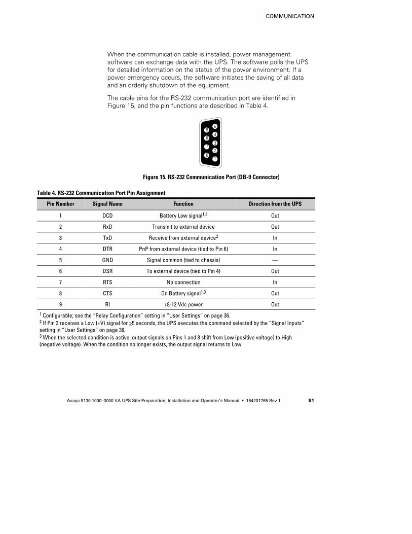
COMMUNICATION
Avaya 9130 1000–3000 VA UPS Site Preparation, Installation and Operator’s Manual S 164201765 Rev 1 51
When the communication cable is installed, power managementsoftware can exchange data with the UPS. The software polls the UPSfor detailed information on the status of the power environment. If apower emergency occurs, the software initiates the saving of all dataand an orderly shutdown of the equipment.
The cable pins for the RS-232 communication port are identified inFigure 15, and the pin functions are described in Table 4.
38
7
9
16
2
4
5
Figure 15. RS-232 Communication Port (DB-9 Connector)
Table 4. RS-232 Communication Port Pin Assignment
Pin Number Signal Name Function Direction from the UPS
1 DCD Battery Low signal1,3 Out
2 RxD Transmit to external device Out
3 TxD Receive from external device2 In
4 DTR PnP from external device (tied to Pin 6) In
5 GND Signal common (tied to chassis) —
6 DSR To external device (tied to Pin 4) Out
7 RTS No connection In
8 CTS On Battery signal1,3 Out
9 RI +8-12 Vdc power Out
1 Configurable; see the “Relay Configuration” setting in “User Settings” on page 36.2 If Pin 3 receives a Low (+V) signal for >5 seconds, the UPS executes the command selected by the “Signal Inputs”setting in “User Settings” on page 36.3 When the selected condition is active, output signals on Pins 1 and 8 shift from Low (positive voltage) to High(negative voltage). When the condition no longer exists, the output signal returns to Low.
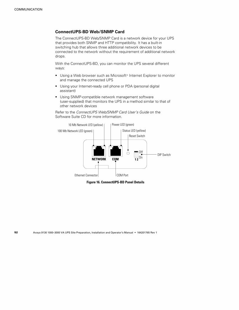
COMMUNICATION
Avaya 9130 1000–3000 VA UPS Site Preparation, Installation and Operator’s Manual S 164201765 Rev 152
ConnectUPS-BD Web/SNMP Card
The ConnectUPS-BD Web/SNMP Card is a network device for your UPSthat provides both SNMP and HTTP compatibility. It has a built-inswitching hub that allows three additional network devices to beconnected to the network without the requirement of additional networkdrops.
With the ConnectUPS-BD, you can monitor the UPS several differentways:
S Using a Web browser such as MicrosoftR Internet Explorer to monitorand manage the connected UPS
S Using your Internet-ready cell phone or PDA (personal digitalassistant)
S Using SNMP-compatible network management software(user-supplied) that monitors the UPS in a method similar to that ofother network devices
Refer to the ConnectUPS Web/SNMP Card User’s Guide on theSoftware Suite CD for more information.
Off
On1 2
10 Mb Network LED (yellow)
100 Mb Network LED (green)
Ethernet Connector
DIP Switch
Reset Switch
COM Port
COMNETWORK
Status LED (yellow)
Power LED (green)
Figure 16. ConnectUPS-BD Panel Details
COMMUNICATION
Avaya 9130 1000–3000 VA UPS Site Preparation, Installation and Operator’s Manual S 164201765 Rev 1 53
Remote Emergency Power-off
REPO is used to shut down the UPS from a distance. This feature canbe used for shutting down the load and the UPS by thermal relay, forinstance in the event of room overtemperature. When REPO isactivated, the UPS shuts down the output and all its power convertersimmediately. The UPS remains on to alarm the fault.
WARNINGThe REPO circuit is an IEC 60950 safety extra low voltage (SELV) circuit. This circuit must beseparated from any hazardous voltage circuits by reinforced insulation.
CAUTIONS The REPO must not be connected to any utility connected circuits. Reinforced insulation
to the utility is required. The REPO switch must have a minimum rating of 24 Vdc and20 mA and be a dedicated latching-type switch not tied into any other circuit. The REPOsignal must remain active for at least 250 ms for proper operation.
S To ensure the UPS stops supplying power to the load during any mode of operation, theinput power must be disconnected from the UPS when the emergency power-off functionis activated.
NOTE For Europe, the emergency switch requirements are detailed in Harmonizeddocument HD-384-48 S1, “Electrical Installation of the Buildings, Part 4: Protection for Safety,Chapter 46: Isolation and Switching.”
REPO Connections
Wire Function Terminal Wire Size Rating Suggested Wire Size
REPO L14–0.32 mm2 (12–22 AWG) 0.82 mm2 (18 AWG)
L2
NOTE Leave the REPO connector installed in the REPO port on the UPS even if the REPOfunction is not needed.
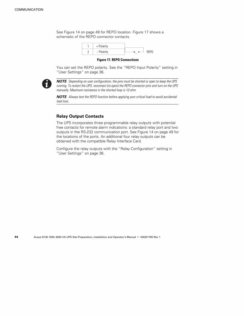
COMMUNICATION
Avaya 9130 1000–3000 VA UPS Site Preparation, Installation and Operator’s Manual S 164201765 Rev 154
See Figure 14 on page 49 for REPO location. Figure 17 shows aschematic of the REPO connector contacts.
– Polarity2
+ Polarity1
REPO
Figure 17. REPO Connections
You can set the REPO polarity. See the “REPO Input Polarity” setting in“User Settings” on page 36.
NOTE Depending on user configuration, the pins must be shorted or open to keep the UPSrunning. To restart the UPS, reconnect (re-open) the REPO connector pins and turn on the UPSmanually. Maximum resistance in the shorted loop is 10 ohm.
NOTE Always test the REPO function before applying your critical load to avoid accidentalload loss.
Relay Output Contacts
The UPS incorporates three programmable relay outputs with potentialfree contacts for remote alarm indications: a standard relay port and twooutputs in the RS-232 communication port. See Figure 14 on page 49 forthe locations of the ports. An additional four relay outputs can beobtained with the compatible Relay Interface Card.
Configure the relay outputs with the “Relay Configuration” setting in“User Settings” on page 36.
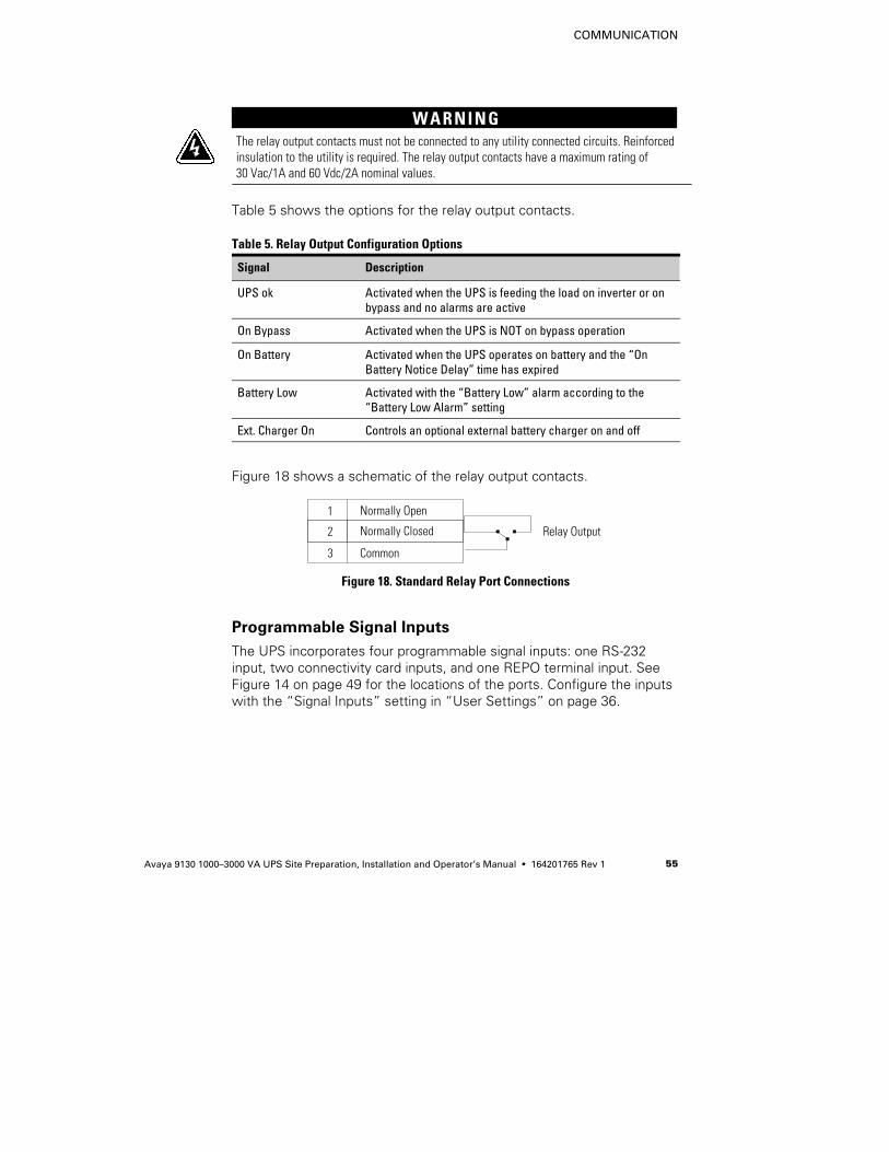
COMMUNICATION
Avaya 9130 1000–3000 VA UPS Site Preparation, Installation and Operator’s Manual S 164201765 Rev 1 55
WARNINGThe relay output contacts must not be connected to any utility connected circuits. Reinforcedinsulation to the utility is required. The relay output contacts have a maximum rating of30 Vac/1A and 60 Vdc/2A nominal values.
Table 5 shows the options for the relay output contacts.
Table 5. Relay Output Configuration Options
Signal Description
UPS ok Activated when the UPS is feeding the load on inverter or onbypass and no alarms are active
On Bypass Activated when the UPS is NOT on bypass operation
On Battery Activated when the UPS operates on battery and the “OnBattery Notice Delay” time has expired
Battery Low Activated with the “Battery Low” alarm according to the“Battery Low Alarm” setting
Ext. Charger On Controls an optional external battery charger on and off
Figure 18 shows a schematic of the relay output contacts.
Common
Normally Closed
3
2
Normally Open1
Relay Output
Figure 18. Standard Relay Port Connections
Programmable Signal Inputs
The UPS incorporates four programmable signal inputs: one RS-232input, two connectivity card inputs, and one REPO terminal input. SeeFigure 14 on page 49 for the locations of the ports. Configure the inputswith the “Signal Inputs” setting in “User Settings” on page 36.
COMMUNICATION
Avaya 9130 1000–3000 VA UPS Site Preparation, Installation and Operator’s Manual S 164201765 Rev 156
Table 6 shows the programmable settings for the signal inputs. Table 7shows the operation logic for the signal inputs.
Table 6. Programmable Signal Inputs
Signal Description
Not Used The input operates only as a serial input (RxD) or has no function.
Force Bypass If active, the UPS is forced to static bypass operation regardless ofthe bypass status.
Remote Shutdown If active, the UPS output turns off after a user-defined remoteshutdown delay. The batteries continue charging. Inactive inputdoes not abort the shutdown countdown and does not cause theUPS to start up automatically.
DelayedShutdown(and restart)
If active, the UPS output turns off after a user-defined delayedshutdown delay. The batteries continue charging. Inactive inputdoes not abort the shutdown countdown but will cause the UPS tostart up automatically if the input voltage exists.
On Generator If active, synchronization is disabled and the UPS transfers tobypass.
Building Alarm 1 If active, the UPS generates the “Building Alarm 1” alarm.
Table 7. Polarity Options
Input Description
High Active state on high voltage (+Udc) level
Low Active state on low voltage (GND or -Udc) level
COMMUNICATION
Avaya 9130 1000–3000 VA UPS Site Preparation, Installation and Operator’s Manual S 164201765 Rev 1 57
Modem Operation
To configure the UPS and modem handling features for remotemonitoring and service, contact your Avaya service representative.
Powerware LanSafe Power Management Software
Each Avaya 9130 UPS ships with Powerware LanSafe PowerManagement Software. To begin installing Powerware LanSafesoftware, see the instructions accompanying the Software Suite CD.
NOTE When installing Powerware LanSafe software, select serial port installation. For theUPS manufacturer and model, select Powerware and Powerware 9130. If thePowerware brand options are not available in your version of the software, selectGeneric UPSs for the manufacturer and Generic XCP for the model.
Powerware LanSafe software provides up-to-date graphics of UPSpower and system data and power flow. It also gives you a completerecord of critical power events, and it notifies you of important UPS orpower information. If there is a power outage and the Avaya 9130 UPSbattery power becomes low, Powerware LanSafe software canautomatically shut down your computer system to protect your databefore the UPS shutdown occurs.

COMMUNICATION
Avaya 9130 1000–3000 VA UPS Site Preparation, Installation and Operator’s Manual S 164201765 Rev 158
Avaya 9130 1000–3000 VA UPS Site Preparation, Installation and Operator’s Manual S 164201765 Rev 1 59
Chapter 6 UPS Maintenance
This section explains how to:
S Care for the UPS and batteries
S Replace the UPS internal batteries and Extended Battery Modules(EBMs)
S Test new batteries
S Recycle used batteries or UPS
S Update the UPS firmware
UPS and Battery Care
For the best preventive maintenance, keep the area around the UPSclean and dust-free. If the atmosphere is very dusty, clean the outside ofthe system with a vacuum cleaner.
For full battery life, keep the UPS at an ambient temperature of25°C (77°F).
NOTE If the UPS requires any type of transportation, verify that the UPS is unplugged andturned off and then disconnect the UPS internal battery connector (see Figure 20 on page 62).
NOTE The batteries in the UPS are rated for a 3–5 year service life. The length of servicelife varies, depending on the frequency of usage and ambient temperature. Batteries usedbeyond expected service life will often have severely reduced runtimes. Replace batteries atleast every 5 years to keep units running at peak efficiency.
Storing the UPS and Batteries
If you store the UPS for a long period, recharge the battery every6 months by connecting the UPS to utility power. The internal batteriescharge to 90% capacity in less than 3 hours. However, Avayarecommends that the batteries charge for 48 hours after long-termstorage. If optional EBMs are installed, see the recharge times listed inTable 19 on page 75.
Check the battery recharge date on the shipping carton label. If the datehas passed and the batteries were never recharged, do not use the UPS.Contact your Avaya service representative.
UPS MAINTENANCE
Avaya 9130 1000–3000 VA UPS Site Preparation, Installation and Operator’s Manual S 164201765 Rev 160
When to Replace Batteries
When the indicator illuminates, the audible alarm beeps, and the“Battery Needs Service” alarm displays, the batteries may needreplacing. Contact your Avaya service representative to order newbatteries. The manufactured date code for the batteries is located on thebattery kit inside the UPS.
Replacing Batteries
NOTE DO NOT DISCONNECT the batteries while the UPS is in Battery mode.
Batteries can be replaced easily without turning the UPS off ordisconnecting the load.
If you prefer to remove input power to change the batteries, see “UPSShutdown” on page 42.
Consider all warnings, cautions, and notes before replacing batteries.
WARNINGS Servicing should be performed by qualified service personnel knowledgeable of batteries
and required precautions. Keep unauthorized personnel away from batteries.
S Batteries can present a risk of electrical shock or burn from high short circuit current.Observe the following precautions: 1) Remove watches, rings, or other metal objects;2) Use tools with insulated handles; 3) Do not lay tools or metal parts on top of batteries,4) Wear rubber gloves and boots.
S When replacing batteries, replace with the same type and number of batteries or batterypacks. Contact your Avaya service representative to order new batteries.
S Proper disposal of batteries is required. Refer to your local codes for disposalrequirements.
S Never dispose of batteries in a fire. Batteries may explode when exposed to flame.
S Do not open or mutilate the battery or batteries. Released electrolyte is harmful to theskin and eyes and may be extremely toxic.
UPS MAINTENANCE
Avaya 9130 1000–3000 VA UPS Site Preparation, Installation and Operator’s Manual S 164201765 Rev 1 61
S Determine if the battery is inadvertently grounded. If inadvertently grounded, removesource from ground. Contact with any part of a grounded battery can result in electricalshock. The likelihood of such shock can be reduced if such grounds are removed duringinstallation and maintenance (applicable to equipment and remote battery supplies nothaving a grounded supply circuit).
S ELECTRIC ENERGY HAZARD. Do not attempt to alter any battery wiring or connectors.Attempting to alter wiring can cause injury.
S Disconnect charging source prior to connecting or disconnecting battery terminals.
Replacing UPS Internal Batteries
CAUTIONThe UPS internal batteries are heavy (see page 70). Use caution when handling the heavybatteries.
The internal batteries are located behind the UPS right front cover(behind the LCD control panel). The internal batteries are packagedtogether as one unit for easier handling.
To replace the batteries in the UPS:
1. Remove the UPS right front cover (see Figure 19).
To remove the cover, remove and retain the two screws on theright side of the cover. Grasp the top and bottom of the cover andslide the cover to the right.
NOTE A ribbon cable connects the LCD control panel to the UPS. Do not pull on the cableor disconnect it.
UPS MAINTENANCE
Avaya 9130 1000–3000 VA UPS Site Preparation, Installation and Operator’s Manual S 164201765 Rev 162
NOTE Leaveribbon cableconnected.
Figure 19. Removing the UPS Right Front Cover
2. Disconnect the internal battery connector (see Figure 20).
3. 1000/1500 VA models only. If the EBM cable is not connected to anEBM, unclip the EBM cable and move it to the left out of the way.See Figure 20.
1000/1500 VA Models 3000 VA Models
Internal BatteryConnector Internal Battery
Connector
EBM Cable
Battery Cover Plate Battery Cover Plate
Figure 20. Disconnecting the UPS Internal Batteries (Shown without EBMs)
4. Grasp an edge of the battery cover plate and pull it forward gently.Remove and retain the battery cover plate. See Figure 20 for thelocation of the battery cover plate.
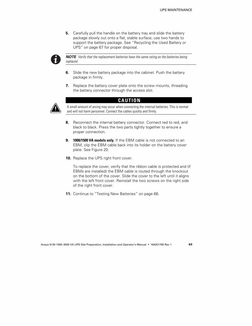
UPS MAINTENANCE
Avaya 9130 1000–3000 VA UPS Site Preparation, Installation and Operator’s Manual S 164201765 Rev 1 63
5. Carefully pull the handle on the battery tray and slide the batterypackage slowly out onto a flat, stable surface; use two hands tosupport the battery package. See “Recycling the Used Battery orUPS” on page 67 for proper disposal.
NOTE Verify that the replacement batteries have the same rating as the batteries beingreplaced.
6. Slide the new battery package into the cabinet. Push the batterypackage in firmly.
7. Replace the battery cover plate onto the screw mounts, threadingthe battery connector through the access slot.
CAUTIONA small amount of arcing may occur when connecting the internal batteries. This is normaland will not harm personnel. Connect the cables quickly and firmly.
8. Reconnect the internal battery connector. Connect red to red, andblack to black. Press the two parts tightly together to ensure aproper connection.
9. 1000/1500 VA models only. If the EBM cable is not connected to anEBM, clip the EBM cable back into its holder on the battery coverplate. See Figure 20.
10. Replace the UPS right front cover.
To replace the cover, verify that the ribbon cable is protected and (ifEBMs are installed) the EBM cable is routed through the knockouton the bottom of the cover. Slide the cover to the left until it alignswith the left front cover. Reinstall the two screws on the right sideof the right front cover.
11. Continue to “Testing New Batteries” on page 66.
UPS MAINTENANCE
Avaya 9130 1000–3000 VA UPS Site Preparation, Installation and Operator’s Manual S 164201765 Rev 164
Replacing EBMs
CAUTIONThe EBM is heavy (see page 70). Lifting the cabinet into the rack requires a minimum of twopeople.
To replace the EBMs:
1. Remove the front cover of each EBM. See Figure 21.
To remove the cover, remove and retain the two screws on theright side of the cover. Grasp the sides of the cover and slide thecover to the left and then away from the cabinet.
Bottom EBM Cable Knockout(underneath cover)
Top EBM Cable Knockout
EBM Cover Hook
Figure 21. Removing the EBM Front Cover
UPS MAINTENANCE
Avaya 9130 1000–3000 VA UPS Site Preparation, Installation and Operator’s Manual S 164201765 Rev 1 65
2. Unplug the EBM cable from the UPS.
If additional EBMs are installed, unplug the EBM cable from thebattery connector on each EBM.
3. If not already installed, install the supplied mounting brackets on thenew EBM(s).
4. Replace the EBM(s). See “Recycling the Used Battery or UPS” onpage 67 for proper disposal.
5. Remove the front cover of each new EBM. See Figure 21.
To remove the cover, remove and retain the two screws on theright side of the cover. Grasp the sides of the cover and slide thecover to the left and then away from the cabinet.
6. For the bottom (or only) EBM, remove the EBM cable knockout onthe top of the cover. See Figure 21 for the location of the top EBMcable knockout.
7. If you are installing more than one new EBM, for each additionalEBM remove the EBM cable knockout on the top and bottom of theEBM front cover. See Figure 21 for the location of the EBM cableknockouts.
8. Plug the new EBM(s) into the UPS. For reference, see Figure 12 onpage 28.
1000/1500 VA models. Connect the EBM connector from the UPS tothe EBM connector on the EBM. Press the two parts tightlytogether to ensure a proper connection.
3000 VA models. Connect the EBM connector from the UPS to theEBM connector on the EBM. Connect red to red, black to black, andgreen to green. Press the two parts tightly together to ensure aproper connection.
All models. To connect a second EBM, unclip the EBM connector onthe first EBM and pull gently to extend the wiring to the EBMconnector on the second EBM. Repeat for any additional EBMs.
9. Verify that the EBM connections are tight and that adequate bendradius and strain relief exist for each cable.
UPS MAINTENANCE
Avaya 9130 1000–3000 VA UPS Site Preparation, Installation and Operator’s Manual S 164201765 Rev 166
10. Replace the EBM front cover.
To replace the cover, verify that the EBM cables are routed throughthe EBM cover knockouts, then slide the cover from the left to theright until it connects with the cover hook near the left side of theEBM cabinet. Reinstall the two screws on the right side of the frontcover. For reference, see Figure 21 on page 64.
Repeat for each additional EBM.
11. Verify that all wiring connecting the UPS and EBM(s) is installedbehind the front covers and is inaccessible to users.
Testing New Batteries
To test new batteries:
1. Plug the UPS into a power outlet for 48 hours to charge thebatteries.
2. Press any button to activate the menu options.
3. Select CONTROL then START BATTERY TEST.
The UPS starts a battery test if the UPS is in Normal mode with noactive alarms and the bypass voltage is acceptable.
During the battery test, the UPS transfers to Battery mode anddischarges the batteries for 25 seconds. The front panel displays“Battery test running” and the percentage of the test completed.
UPS MAINTENANCE
Avaya 9130 1000–3000 VA UPS Site Preparation, Installation and Operator’s Manual S 164201765 Rev 1 67
Recycling the Used Battery or UPS
Contact your local recycling or hazardous waste center for informationon proper disposal of the used battery or UPS.
WARNINGS Do not dispose of the battery or batteries in a fire. Batteries may explode. Proper
disposal of batteries is required. Refer to your local codes for disposal requirements.
S Do not open or mutilate the battery or batteries. Released electrolyte is harmful to theskin and eyes. It may be toxic.
CAUTIONDo not discard the UPS or the UPS batteries in the trash. This product contains sealed,lead-acid batteries and must be disposed of properly. For more information, contact yourlocal recycling/reuse or hazardous waste center.
CAUTIONDo not discard waste electrical or electronic equipment (WEEE) in the trash. For properdisposal, contact your local recycling/reuse or hazardous waste center.
Updating the UPS Firmware
To keep the UPS firmware updated with the latest improvementsand benefits, visit www.powerware.com/avaya often for updates. Youcan download the latest firmware version and the instructions forinstalling it.

UPS MAINTENANCE
Avaya 9130 1000–3000 VA UPS Site Preparation, Installation and Operator’s Manual S 164201765 Rev 168
Avaya 9130 1000–3000 VA UPS Site Preparation, Installation and Operator’s Manual S 164201765 Rev 1 69
Chapter 7 Specifications
Model Specifications
This section provides the following specifications:
S Communication options
S Model lists
S Weights and dimensions
S Electrical input and output
S Environmental and safety
S Battery
Table 8. Communication Options
Communication Bay (1) available independent communication bay for connectivity cards
Compatible Connectivity Cards ConnectUPS-BD Web/SNMP Card
Communication Ports RS-232 (DB-9): 1200–9600 bpsUSB: 9600 bps
Signal Inputs (4) programmable signal inputs (signal and signal return) for indicating buildingalarms or other use
Relay Output Contacts (1) three-pole connector with (1) contact closure
Table 9. Extended Battery Module Model List
EBM Model Battery Voltage For Power Ratings
1000 VA 36 Vdc 1000 VA
1500 VA 48 Vdc 1500 VA
3000 VA 72 Vdc 3000 VA
SPECIFICATIONS
Avaya 9130 1000–3000 VA UPS Site Preparation, Installation and Operator’s Manual S 164201765 Rev 170
Table 10. UPS Model List
Model Power Level Rear Panel Diagram
1000 VA, 120V (790341054021 1000) 1000 VA / 900W Figure 22 on page 76
1500 VA, 120V (790341054045 1500) 1500 VA / 1350W Figure 24 on page 76
3000 VA, 120V (790341054069 3000) 3000 VA / 2700W Figure 26 on page 77
1000 VA, 208/230/240V (790341054038 1000i) 1000 VA / 900W Figure 23 on page 76
1500 VA, 208/230/240V (790341054052 1500i) 1500 VA / 1350W Figure 25 on page 77
3000 VA, 208/230/240V (790341054076 3000i) 3000 VA / 2700W Figure 27 on page 77
Table 11. Weights and Dimensions
UPS Model Dimensions (H×W×D) Weight
1000 VA 86.5×438×430 mm(3.4”×17.2”×16.9”)
16.0 kg (35.3 lb)
1500 VA 86.5×438×430 mm(3.4”×17.2”×16.9”)
19.5 kg (43.0 lb)
3000 VA 86.5×438×600 mm(3.4”×17.2”×23.6”)
29.5 kg (65.0 lb)
EBM Model Dimensions (H×W×D) Weight
1000 VA 86.5×438×430 mm(3.4”×17.2”×16.9”)
22.1 kg (48.7 lb)
1500 VA 86.5×438×430 mm(3.4”×17.2”×16.9”)
28.1 kg (62.0 lb)
3000 VA 86.5×438×600 mm(3.4”×17.2”×23.6”)
41.0 kg (90.6 lb)
Table 12. Electrical Input
Nominal Frequency 50/60 Hz auto-sensing
Frequency Range 40–70 Hz before transfer to battery
Bypass Voltage Range +10/-15% of nominal (default)
Noise Filtering MOVs for normal and common mode noise
SPECIFICATIONS
Avaya 9130 1000–3000 VA UPS Site Preparation, Installation and Operator’s Manual S 164201765 Rev 1 71
Table 13. Electrical Input
Model Default Input(Voltage/Current)
Selectable InputVoltages
Voltage Rangeat 100% Load
1000 VA, 120V 120V / 8.3A 100*, 110**, 120, 127 80–138 Vac
1500 VA, 120V 120V / 12.5A 100*, 110**, 120, 127 80–138 Vac
3000 VA, 120V 120V / 25A 100*, 110**, 120, 127 90–138 Vac
1000 VA, 208/230/240V 230V / 4.3A 200*, 208**, 220, 230, 240 160–276 Vac
1500 VA, 208/230/240V 230V / 6.5A 200*, 208**, 220, 230, 240 160–276 Vac
3000 VA, 208/230/240V 230V / 13.0A 200*, 208**, 220, 230, 240 180–276 Vac
* 100V and 200V are derated by 20%.** 110V and 208V are derated by 10%.
Table 14. Electrical Input Connections
Model Input Connection Input Cable
1000 VA, 120V 5-15P Attached line cord
1500 VA, 120V 5-15P Attached line cord
3000 VA, 120V L5-30P Attached line cord
1000 VA, 208/230/240V IEC C14-10A Schuko 10A to IEC 320-10A
1500 VA, 208/230/240V IEC C14-10A Schuko 10A to IEC 320-10A
3000 VA, 208/230/240V IEC C20-16A Schuko 16A to IEC 320-16A
SPECIFICATIONS
Avaya 9130 1000–3000 VA UPS Site Preparation, Installation and Operator’s Manual S 164201765 Rev 172
Table 15. Electrical Output
Normal Mode Battery Mode
Voltage Regulation ±2% Nominal output voltage ±3%
Efficiency >95% (High Efficiency mode), >88% >79.5% (700 VA), >82% (1000–1500 VA),>84% (3000 VA)
Frequency Regulation Sync with line ±3 Hz of nominal linefrequency (outside this range: ±0.1 Hz of
auto-selected nominal frequency)
±0.1 Hz of auto-selected nominalfrequency
120V Models 208/230/240V Models
Nominal Outputs 100/110/120/127V (voltage configurableor auto-sensing)
1000/1500/3000 VA0.9/1.35/2.7 kW
200/208/220/230/240V(voltage configurable or auto-sensing)
1000/1500/3000 VA0.9/1.35/2.7 kW
Frequency 50 or 60 Hz, autosensing or configurable as a frequency converter
Output Overload (Normal Mode) 100–102%: Activates Overload alarm. (Level 1)102–129%: Load transfers to Bypass mode after 12 seconds. (Level 2)130–149%: Load transfers to Bypass mode after 2 seconds. (Level 3)
>150%: Load transfers to Bypass mode after 100 ms. (Level 4)NOTE Default configuration transfers immediately to Bypass at >102%.
Output Overload (Bypass Mode) 100–109%: Activates Overload alarm. (Level 1)110–129%: UPS shuts down after 5 minutes. (Level 2)
130–149%: UPS shuts down after 15 seconds. (Level 3)>150%: UPS shuts down after 300 ms. (Level 4)
Output Overload (Battery Mode) 100–102%: Activates Overload alarm. (Level 1)102–129%: UPS shuts down after 12 seconds. (Level 2)130–149%: UPS shuts down after 2 seconds. (Level 3)
>150%: UPS shuts down after 100 ms. (Level 4)
Voltage Waveform Sine wave
Harmonic Distortion <3% THD on linear load; <5% THD on non-linear load
Transfer Time Online mode: 0 ms (no break)High Efficiency mode: 10 ms maximum (due to loss of utility)
Power Factor 0.9
Load Crest Factor 3 to 1
SPECIFICATIONS
Avaya 9130 1000–3000 VA UPS Site Preparation, Installation and Operator’s Manual S 164201765 Rev 1 73
Table 16. Electrical Output Connections
Model Output Connections Output Cables
1000 VA, 120V (6) 5-15R None
1500 VA, 120V (6) 5-15R None
3000 VA, 120V (1) L5-30R, (6) 5-20R,(2) 20A AC breakers
None
1000 VA, 208/230/240V (6) IEC 320-10A (2) IEC-IEC 10A, (1) IEC 320-10A to Schuko 3-strip
1500 VA, 208/230/240V (6) IEC 320-10A (2) IEC-IEC 10A, (1) IEC 320-10A to Schuko 3-strip
3000 VA, 208/230/240V (8) IEC 320-10A, (1) IEC 320-16A (2) IEC-IEC 10A, (1) IEC 320-16A to Schuko 3-strip
SPECIFICATIONS
Avaya 9130 1000–3000 VA UPS Site Preparation, Installation and Operator’s Manual S 164201765 Rev 174
Table 17. Environmental and Safety
120V Models 208/230/240V Models
Surge Suppression ANSI C62.41 Category B3(6 KV Ring and Combination)
EN 61000-2-2EN 61000-4-2, Level 3EN 61000-4-3, Level 2
EN 61000-4-4, Level 2 (also on signal ports)EN 6100-4-5, Level 3 Criteria A
EN 61000-4-6, Level 2EN 61000-4-8, Level 2
EN 6100-4-11
EMC Certifications <1500 VA: FCC Class B, VCCI Class B,EN 55022 Class B
3000 VA: FCC Class A, VCCI Class A,EN 55022 Class A
CE per IEC/EN 62040-2,Emissions: Category C1,Immunity: Category C2
EMC (Emissions) IEC 62040-2:ed2:2005 / EN 62040-2:2006
Safety Conformance UL 1778, IEC 62040-1-1, IEC 60950-1
Agency Markings CE, UL, CUL, NOM
Operating Temperature 0°C to 40°C (32°F to 104°F) in Online mode, with linear derating for altitudeNOTE Thermal protection switches load to Bypass in case of overheating.
Storage Temperature -20°C to 40°C (-4°F to 104°F) with batteries-25°C to 55°C (-13°F to 131°F) without batteries
Transit Temperature -25°C to 55°C (-13°F to 131°F)
Relative Humidity 5–90% noncondensing
Operating Altitude Up to 3,000 meters (9,843 ft) above sea level
Transit Altitude Up to 10,000 meters (32,808 ft) above sea level
Audible Noise <50 dBA at 1 meter typical
Leakage Current <1.5 mA
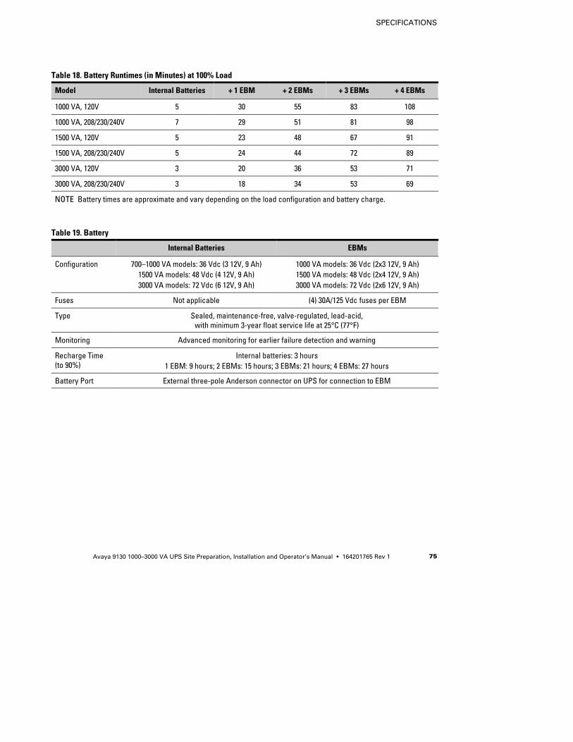
SPECIFICATIONS
Avaya 9130 1000–3000 VA UPS Site Preparation, Installation and Operator’s Manual S 164201765 Rev 1 75
Table 18. Battery Runtimes (in Minutes) at 100% Load
Model Internal Batteries + 1 EBM + 2 EBMs + 3 EBMs + 4 EBMs
1000 VA, 120V 5 30 55 83 108
1000 VA, 208/230/240V 7 29 51 81 98
1500 VA, 120V 5 23 48 67 91
1500 VA, 208/230/240V 5 24 44 72 89
3000 VA, 120V 3 20 36 53 71
3000 VA, 208/230/240V 3 18 34 53 69
NOTE Battery times are approximate and vary depending on the load configuration and battery charge.
Table 19. Battery
Internal Batteries EBMs
Configuration 700–1000 VA models: 36 Vdc (3 12V, 9 Ah)1500 VA models: 48 Vdc (4 12V, 9 Ah)3000 VA models: 72 Vdc (6 12V, 9 Ah)
1000 VA models: 36 Vdc (2x3 12V, 9 Ah)1500 VA models: 48 Vdc (2x4 12V, 9 Ah)3000 VA models: 72 Vdc (2x6 12V, 9 Ah)
Fuses Not applicable (4) 30A/125 Vdc fuses per EBM
Type Sealed, maintenance-free, valve-regulated, lead-acid,with minimum 3-year float service life at 25°C (77°F)
Monitoring Advanced monitoring for earlier failure detection and warning
Recharge Time(to 90%)
Internal batteries: 3 hours1 EBM: 9 hours; 2 EBMs: 15 hours; 3 EBMs: 21 hours; 4 EBMs: 27 hours
Battery Port External three-pole Anderson connector on UPS for connection to EBM
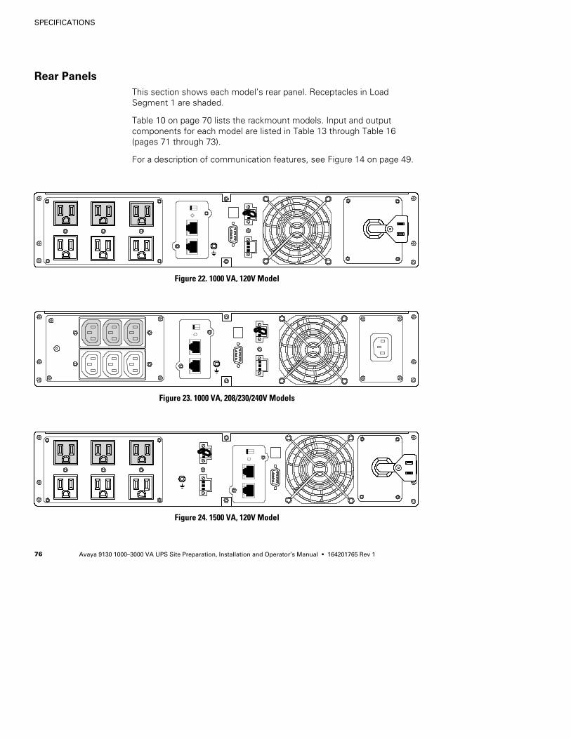
SPECIFICATIONS
Avaya 9130 1000–3000 VA UPS Site Preparation, Installation and Operator’s Manual S 164201765 Rev 176
Rear Panels
This section shows each model’s rear panel. Receptacles in LoadSegment 1 are shaded.
Table 10 on page 70 lists the rackmount models. Input and outputcomponents for each model are listed in Table 13 through Table 16(pages 71 through 73).
For a description of communication features, see Figure 14 on page 49.
Figure 22. 1000 VA, 120V Model
Figure 23. 1000 VA, 208/230/240V Models
Figure 24. 1500 VA, 120V Model
SPECIFICATIONS
Avaya 9130 1000–3000 VA UPS Site Preparation, Installation and Operator’s Manual S 164201765 Rev 1 77
Figure 25. 1500 VA, 208/230/240V Models
Figure 26. 3000 VA, 120V Model
Figure 27. 3000 VA, 208/230/240V Models

SPECIFICATIONS
Avaya 9130 1000–3000 VA UPS Site Preparation, Installation and Operator’s Manual S 164201765 Rev 178
Avaya 9130 1000–3000 VA UPS Site Preparation, Installation and Operator’s Manual S 164201765 Rev 1 79
Chapter 8 Troubleshooting
The Avaya 9130 is designed for durable, automatic operation and alsoalerts you whenever potential operating problems may occur. Usuallythe alarms shown by the control panel do not mean that the outputpower is affected. Instead, they are preventive alarms intended to alertthe user.
In general:
S Events are silent conditions that are recorded in the Event Log asstatus information, such as “Clock Set Done.”
S Notices are announced by a beep every 5 seconds, recorded in theEvent Log, and displayed on the LCD. Examples are “UPS onBattery” and “UPS on Bypass.”
S Alarms are announced by a beep every second, recorded in the EventLog, displayed on the LCD, and the Alarm indicator illuminates.Examples are “Output Overload” and “Heatsink Overtemperature.”
Use the following troubleshooting chart to determine the UPS alarmcondition.
Typical Alarms and Conditions
To check the UPS Status menu for a list of active alarms:
1. Press any button on the front panel display to activate the menuoptions.
2. Press the button until UPS STATUS displays.
3. Press the Enter button to display the list of active alarms.
TROUBLESHOOTING
Avaya 9130 1000–3000 VA UPS Site Preparation, Installation and Operator’s Manual S 164201765 Rev 180
To check the Event Log for a history of conditions:
1. Press any button on the front panel display to activate the menuoptions.
2. Press the button until EVENT LOG displays.
3. Press the Enter button to display the list of conditions.
You can also retrieve the entire Event Log in ASCII format. See“Retrieving the Event Log” on page 43.
The following table describes typical alarms and conditions.
Alarm or Condition Possible Cause Action
On Battery
LED is on.1 beep every 5 seconds.
A utility failure has occurred andthe UPS is in Battery mode.
The UPS is powering the equipment with batterypower. Prepare your equipment for shutdown.
Battery Low
LED is flashing slowly.1 beep every second.
The UPS is in Battery mode andthe battery is running low.
This warning is approximate, and the actual time toshutdown may vary significantly. Depending on theUPS load and number of Extended Battery Modules(EBMs), the “Battery Low” warning may occurbefore the batteries reach 25% capacity. SeeTable 18 on page 75 for estimated runtimes.
On Bypass
LED is on.1 beep every 5 seconds.
The UPS is in Bypass mode. The equipment transferred to bypass utility power.Battery mode is not available and your equipment isnot protected; however, the utility power continuesto be passively filtered by the UPS. Check for one ofthe following alarms: overtemperature, overload, orUPS failure.
On Bypass
LED is on.No beeping.
The UPS is on bypass whileoperating on the High Efficiencysetting.
The equipment transferred to bypass utility poweras a normal function of High Efficiency operation.Battery mode is available and your equipment isprotected.
Batteries Disconnected
LED is on.1 beep every second.
The UPS does not recognize theinternal batteries.
If the condition persists, contact your Avayaservice representative.
The batteries are disconnected. Verify that all batteries are properly connected. Ifthe condition persists, contact your Avaya servicerepresentative.
TROUBLESHOOTING
Avaya 9130 1000–3000 VA UPS Site Preparation, Installation and Operator’s Manual S 164201765 Rev 1 81
ActionPossible CauseAlarm or Condition
Overload
LED is on.1 beep every second.
Power requirements exceed theUPS capacity (greater than100% of nominal; see page 72 forspecific output overloadranges).
Remove some of the equipment from the UPS. TheUPS continues to operate, but may switch toBypass mode or shut down if the load increases.The alarm resets when the condition becomesinactive.
Overtemperature
LED is on.1 beep every second.
The UPS internal temperature istoo high or a fan has failed.At the warning level, the UPSgenerates the alarm but remainsin the current operating state.If the temperature rises another10°C, the UPS transfers toBypass mode or shuts down ifbypass is unusable.
If the UPS transferred to Bypass mode, the UPS willreturn to normal operation when the temperaturedrops 5°C below the warning level.If the condition persists, shut down the UPS. Clearvents and remove any heat sources. Allow the UPSto cool. Ensure the airflow around the UPS is notrestricted. Restart the UPS.If the condition continues to persist, contact yourAvaya service representative.
Battery Overvoltage
LED is on.1 beep every second.
The UPS battery voltage is toohigh.
The UPS turns off the charger until the next powerrecycle. Contact your Avaya servicerepresentative.
Site Wiring Fault
LED is on.1 beep every second.
“L” Models Only. Ground wireconnection does not exist, or theline and neutral wires arereversed in the wall outlet.
Have a qualified electrician correct the wiring.
“i” Models Only. The polarity ofthe UPS input power cordconnector is incorrect.
Rotate the Schuko input connector.
“i” Models Only. The groundwire connection does not exist.
Have a qualified electrician correct the wiring. Ifthe UPS is installed to input supply without ground,disable the “Site Wiring Fault Alarm” setting (see“User Settings” on page 36).
The UPS does not provide theexpected backup time.
The batteries need charging orservice.
Apply utility power for 48 hours to charge thebatteries. If the condition persists, contact yourAvaya service representative.
Power is not available at theUPS output receptacles.
The UPS is in Standby mode. Supply power to the connected equipment: Pressthe On/Off button for at least 1 second, until thefront panel displays “UPS starting...”.
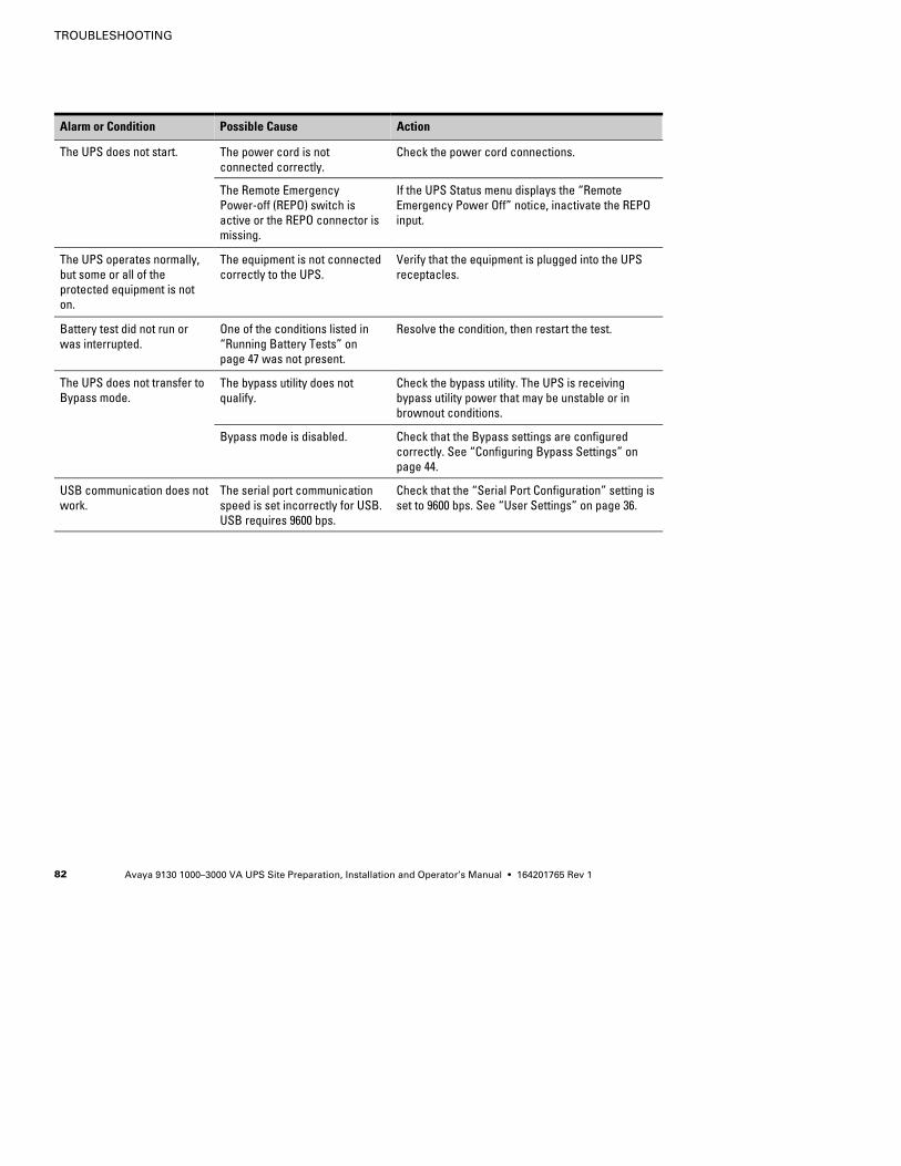
TROUBLESHOOTING
Avaya 9130 1000–3000 VA UPS Site Preparation, Installation and Operator’s Manual S 164201765 Rev 182
ActionPossible CauseAlarm or Condition
The UPS does not start. The power cord is notconnected correctly.
Check the power cord connections.
The Remote EmergencyPower-off (REPO) switch isactive or the REPO connector ismissing.
If the UPS Status menu displays the “RemoteEmergency Power Off” notice, inactivate the REPOinput.
The UPS operates normally,but some or all of theprotected equipment is noton.
The equipment is not connectedcorrectly to the UPS.
Verify that the equipment is plugged into the UPSreceptacles.
Battery test did not run orwas interrupted.
One of the conditions listed in“Running Battery Tests” onpage 47 was not present.
Resolve the condition, then restart the test.
The UPS does not transfer toBypass mode.
The bypass utility does notqualify.
Check the bypass utility. The UPS is receivingbypass utility power that may be unstable or inbrownout conditions.
Bypass mode is disabled. Check that the Bypass settings are configuredcorrectly. See “Configuring Bypass Settings” onpage 44.
USB communication does notwork.
The serial port communicationspeed is set incorrectly for USB.USB requires 9600 bps.
Check that the “Serial Port Configuration” setting isset to 9600 bps. See “User Settings” on page 36.
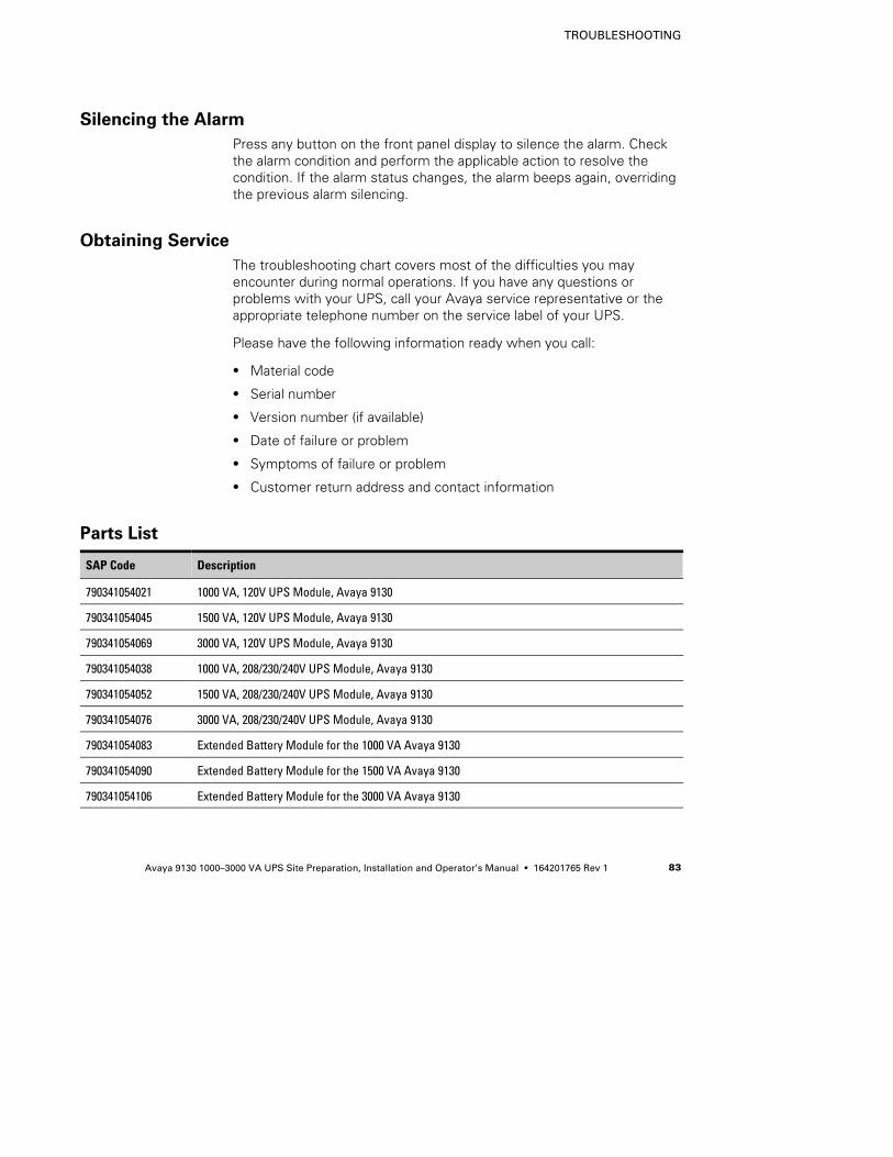
TROUBLESHOOTING
Avaya 9130 1000–3000 VA UPS Site Preparation, Installation and Operator’s Manual S 164201765 Rev 1 83
Silencing the Alarm
Press any button on the front panel display to silence the alarm. Checkthe alarm condition and perform the applicable action to resolve thecondition. If the alarm status changes, the alarm beeps again, overridingthe previous alarm silencing.
Obtaining Service
The troubleshooting chart covers most of the difficulties you mayencounter during normal operations. If you have any questions orproblems with your UPS, call your Avaya service representative or theappropriate telephone number on the service label of your UPS.
Please have the following information ready when you call:
S Material code
S Serial number
S Version number (if available)
S Date of failure or problem
S Symptoms of failure or problem
S Customer return address and contact information
Parts List
SAP Code Description
790341054021 1000 VA, 120V UPS Module, Avaya 9130
790341054045 1500 VA, 120V UPS Module, Avaya 9130
790341054069 3000 VA, 120V UPS Module, Avaya 9130
790341054038 1000 VA, 208/230/240V UPS Module, Avaya 9130
790341054052 1500 VA, 208/230/240V UPS Module, Avaya 9130
790341054076 3000 VA, 208/230/240V UPS Module, Avaya 9130
790341054083 Extended Battery Module for the 1000 VA Avaya 9130
790341054090 Extended Battery Module for the 1500 VA Avaya 9130
790341054106 Extended Battery Module for the 3000 VA Avaya 9130

TROUBLESHOOTING
Avaya 9130 1000–3000 VA UPS Site Preparation, Installation and Operator’s Manual S 164201765 Rev 184


*1642017651*164201765 1