Embed Size (px)
Citation preview

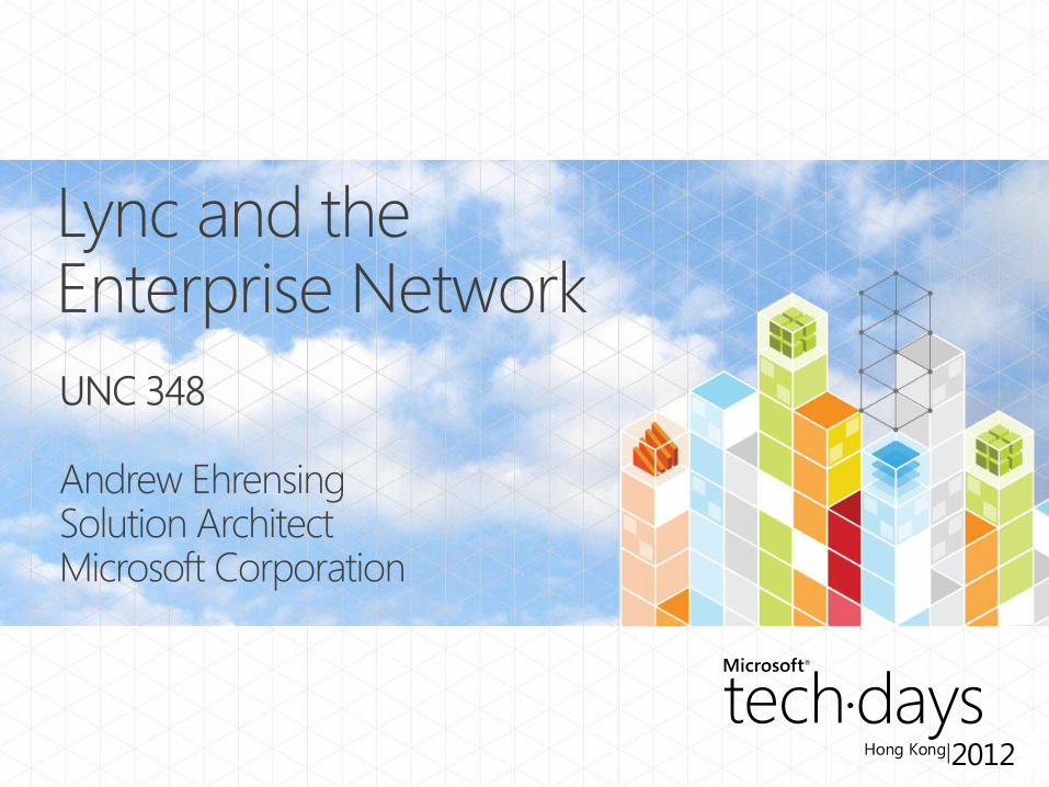

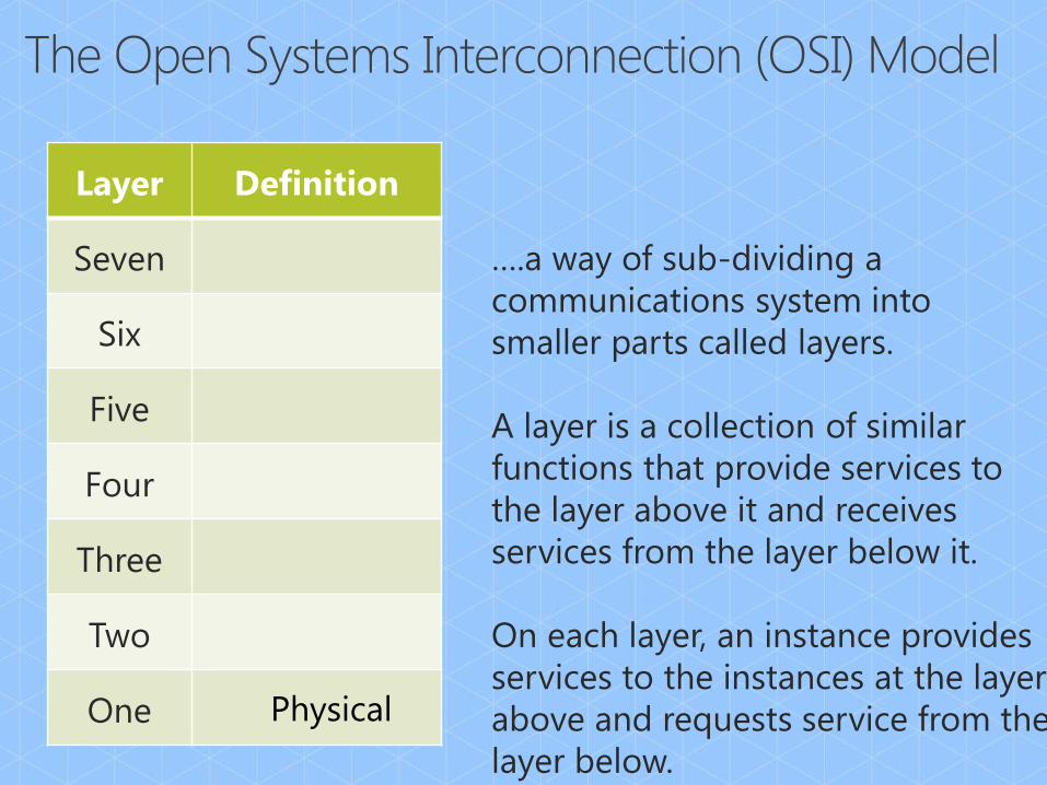
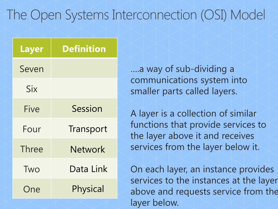
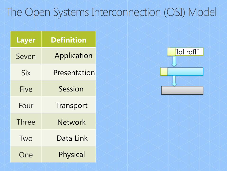
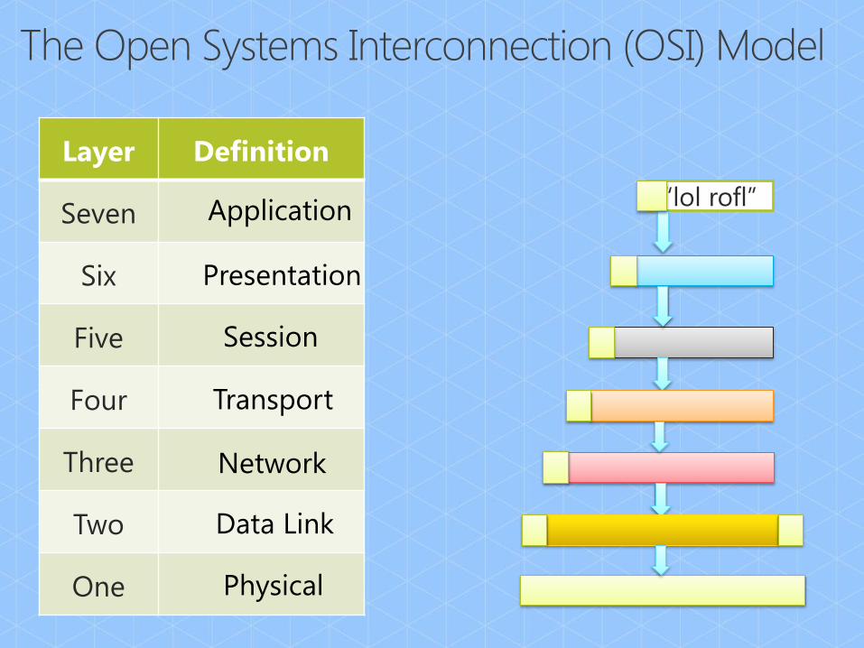
Layer Definition
Seven
Six
Five
Four
Three
Two
One
….a way of sub-dividing a
communications system into
smaller parts called layers.
A layer is a collection of similar
functions that provide services to
the layer above it and receives
services from the layer below it.
On each layer, an instance provides
services to the instances at the layer
above and requests service from the
layer below.
- Wikipedia
Layer Definition
Seven
Six
Five
Four
Three
Two
One Physical
….a way of sub-dividing a
communications system into
smaller parts called layers.
A layer is a collection of similar
functions that provide services to
the layer above it and receives
services from the layer below it.
On each layer, an instance provides
services to the instances at the layer
above and requests service from the
layer below.
- Wikipedia
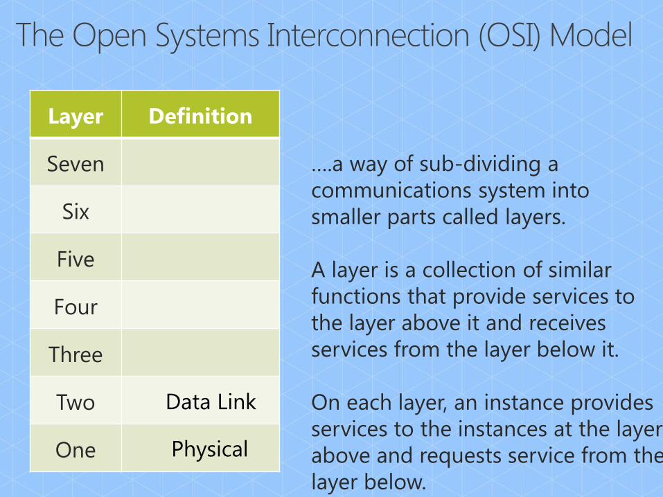
Layer Definition
Seven
Six
Five
Four
Three
Two
One Physical
Data Link
….a way of sub-dividing a
communications system into
smaller parts called layers.
A layer is a collection of similar
functions that provide services to
the layer above it and receives
services from the layer below it.
On each layer, an instance provides
services to the instances at the layer
above and requests service from the
layer below.
- Wikipedia
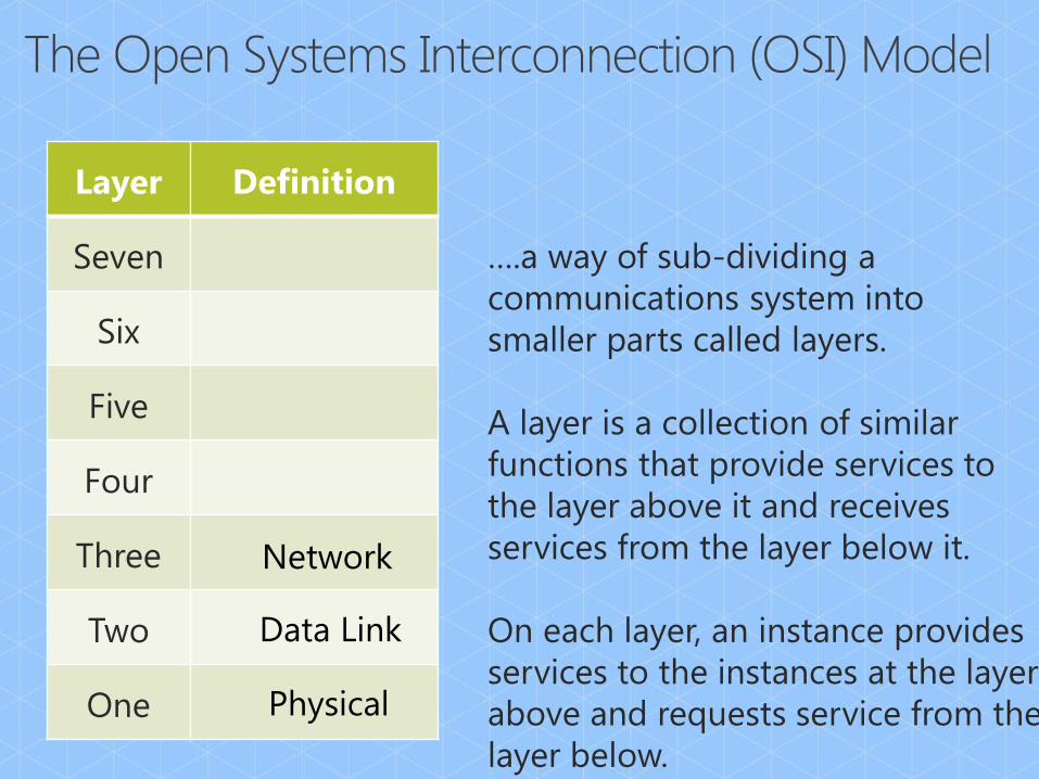
Layer Definition
Seven
Six
Five
Four
Three
Two
One Physical
Data Link
Network
….a way of sub-dividing a
communications system into
smaller parts called layers.
A layer is a collection of similar
functions that provide services to
the layer above it and receives
services from the layer below it.
On each layer, an instance provides
services to the instances at the layer
above and requests service from the
layer below.
- Wikipedia
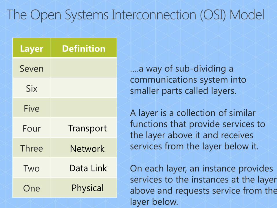
Layer Definition
Seven
Six
Five
Four
Three
Two
One Physical
Data Link
Network
Transport
….a way of sub-dividing a
communications system into
smaller parts called layers.
A layer is a collection of similar
functions that provide services to
the layer above it and receives
services from the layer below it.
On each layer, an instance provides
services to the instances at the layer
above and requests service from the
layer below.
- Wikipedia
Layer Definition
Seven
Six
Five
Four
Three
Two
One Physical
Data Link
Network
Transport
Session
….a way of sub-dividing a
communications system into
smaller parts called layers.
A layer is a collection of similar
functions that provide services to
the layer above it and receives
services from the layer below it.
On each layer, an instance provides
services to the instances at the layer
above and requests service from the
layer below.
- Wikipedia

Layer Definition
Seven
Six
Five
Four
Three
Two
One Physical
Data Link
Network
Transport
Session
Presentation
….a way of sub-dividing a
communications system into
smaller parts called layers.
A layer is a collection of similar
functions that provide services to
the layer above it and receives
services from the layer below it.
On each layer, an instance provides
services to the instances at the layer
above and requests service from the
layer below.
- Wikipedia
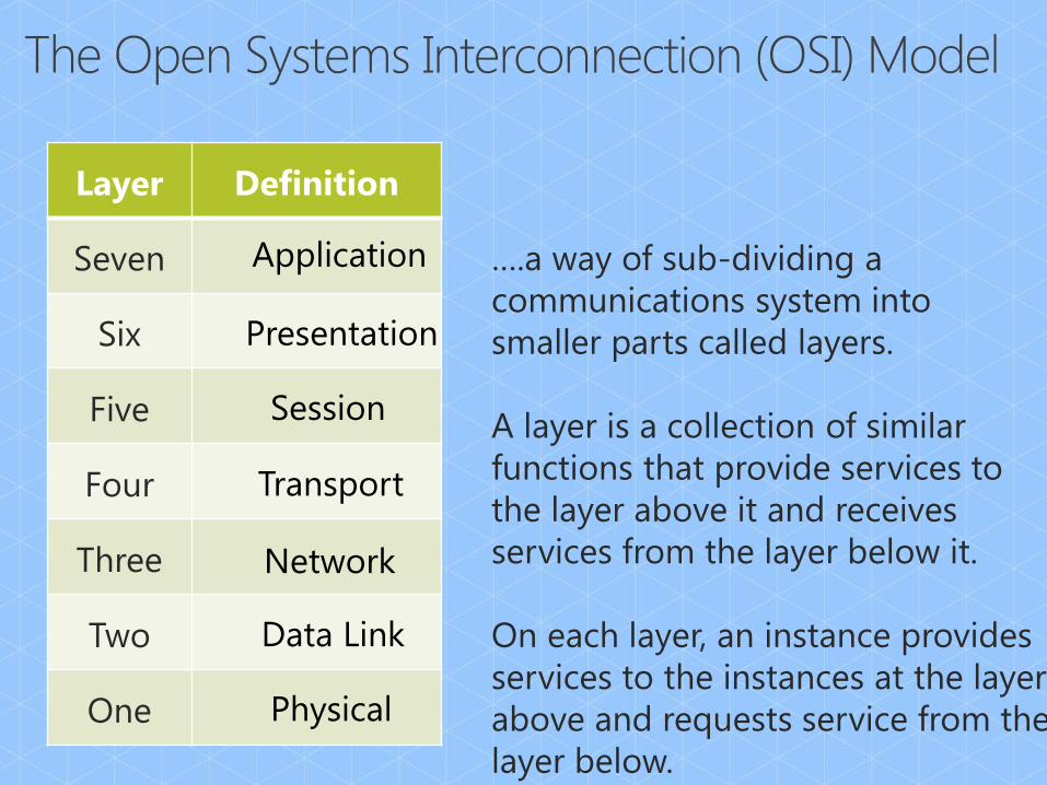
Layer Definition
Seven
Six
Five
Four
Three
Two
One Physical
Data Link
Network
Transport
Session
Presentation
Application ….a way of sub-dividing a
communications system into
smaller parts called layers.
A layer is a collection of similar
functions that provide services to
the layer above it and receives
services from the layer below it.
On each layer, an instance provides
services to the instances at the layer
above and requests service from the
layer below.
- Wikipedia
Layer Definition
Seven
Six
Five
Four
Three
Two
One Physical
Data Link
Network
Transport
Session
Presentation
Application
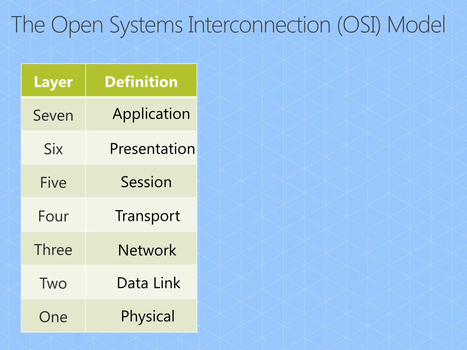
Layer Definition
Seven
Six
Five
Four
Three
Two
One Physical
Data Link
Network
Transport
Session
Presentation
Application “lol rofl”

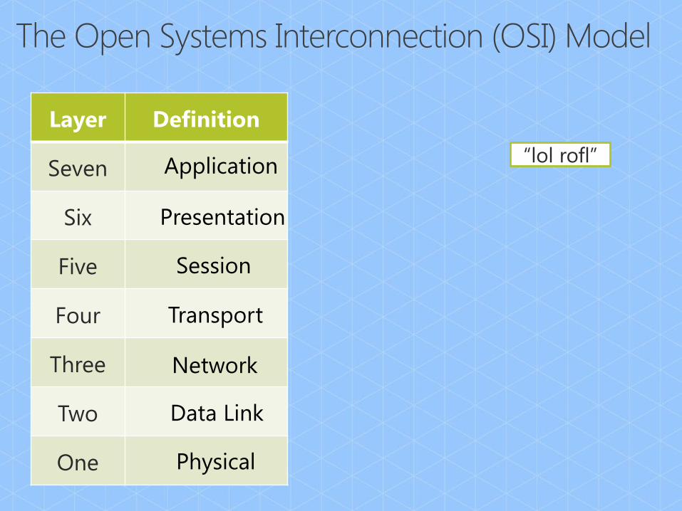
Layer Definition
Seven
Six
Five
Four
Three
Two
One Physical
Data Link
Network
Transport
Session
Presentation
Application “lol rofl”
Layer Definition
Seven
Six
Five
Four
Three
Two
One Physical
Data Link
Network
Transport
Session
Presentation
Application “lol rofl”
Layer Definition
Seven
Six
Five
Four
Three
Two
One Physical
Data Link
Network
Transport
Session
Presentation
Application “lol rofl”
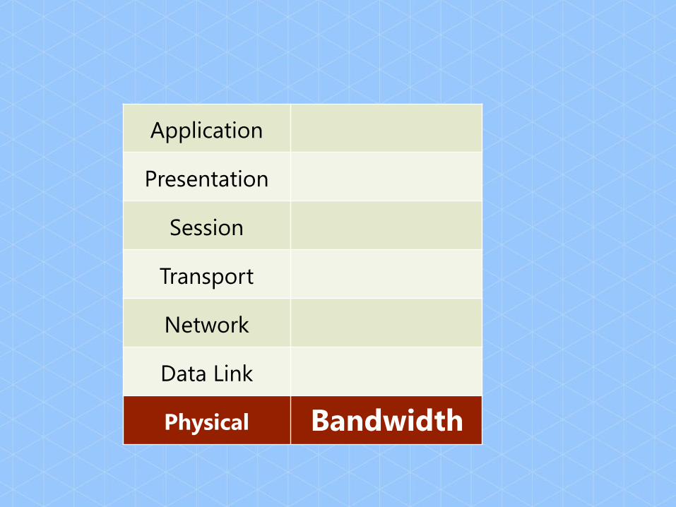
Application
Presentation
Session
Transport
Network
Data Link
Physical Bandwidth
Packetization and Sampling
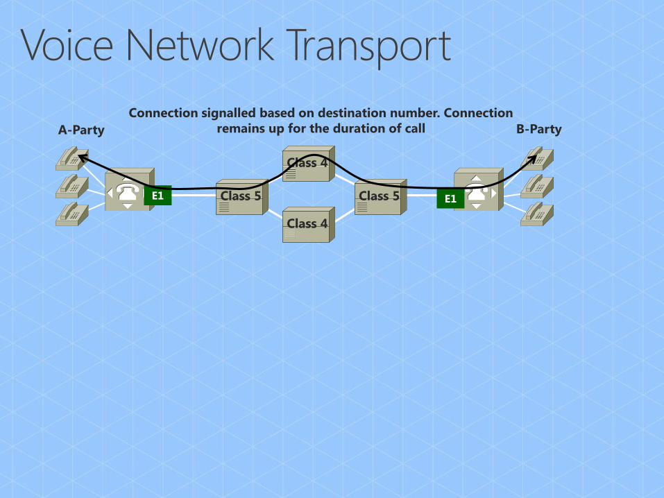
Connection signalled based on destination number. Connection
remains up for the duration of call
Class 4
Class 4
Class 5 Class 5 E1 E1
A-Party B-Party

Connection signalled based on destination number. Connection
remains up for the duration of call
Class 4
Class 4
Class 5 Class 5 E1 E1
Each packet contains destination address.
packets are routed by hop, flow or destination.
10.1.2.1 Voice 10.1.2.1 Voice
A-Party
10.1.1.1
B-Party
10.1.2.1
A-Party B-Party

Stream of
G.711 bytes
IP Packet (no payload)
58 Payload Header
58 160 bytes
G.711
Calculating the “Truck” overhead
1 second / 20ms sample = 50 payloads
50 “payloads per second” * 58 bytes (truck) * 8 bits/byte = 23.2kb/s

Stream of
G.711 bytes
IP Packet
58 Payload Header
58
480 bytes G.711
Calculating the “Truck” overhead
1 second / 60ms sample = 16 2/3 packets
16 2/3 “Trucks per second” * 58 * 8 bits/byte = 7.73kb/s

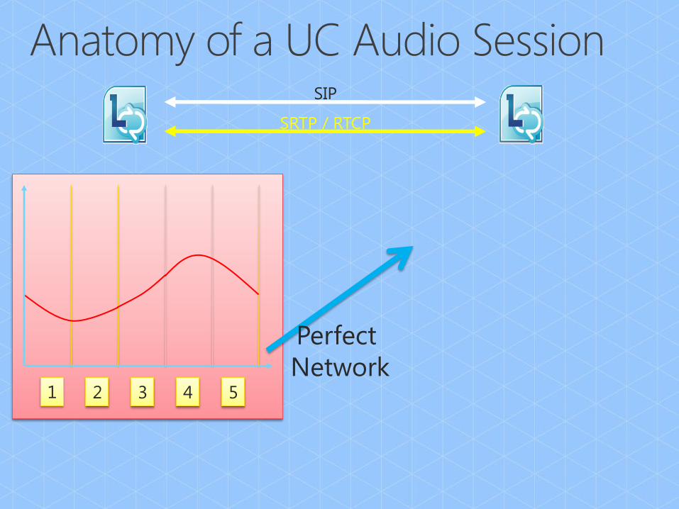
SRTP / RTCP
SIP
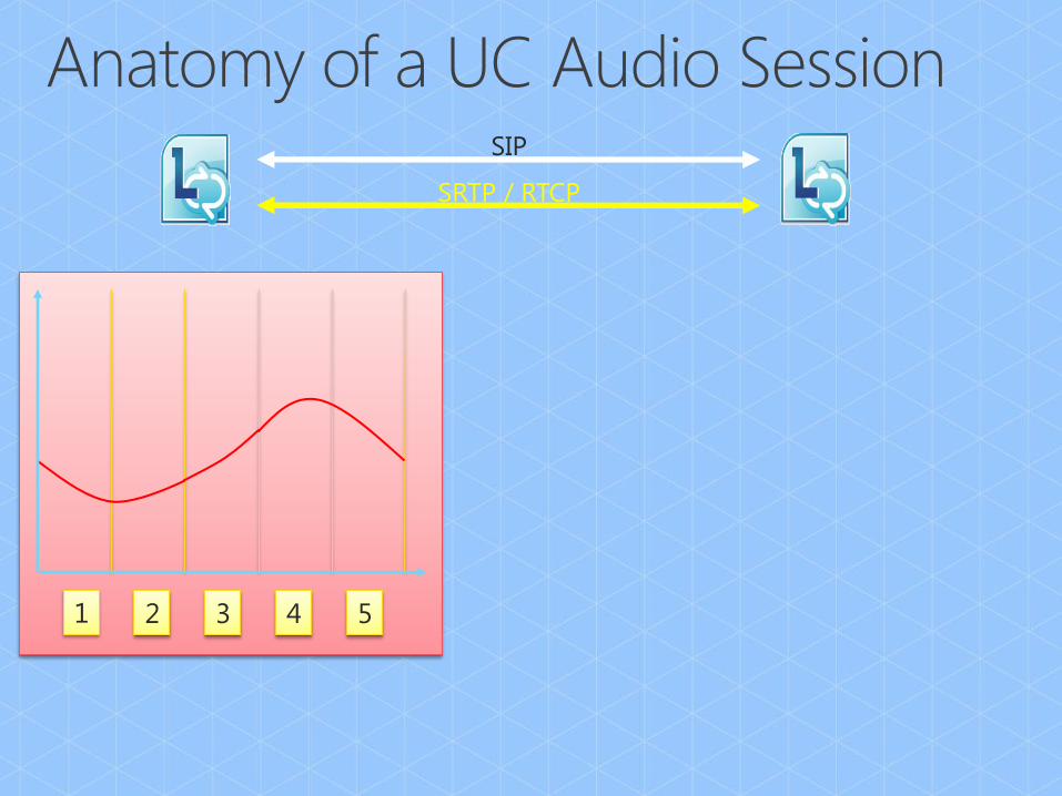
1 2 3 4 5
SRTP / RTCP
SIP
1 2 3 4 5
SRTP / RTCP
SIP
Perfect
Network
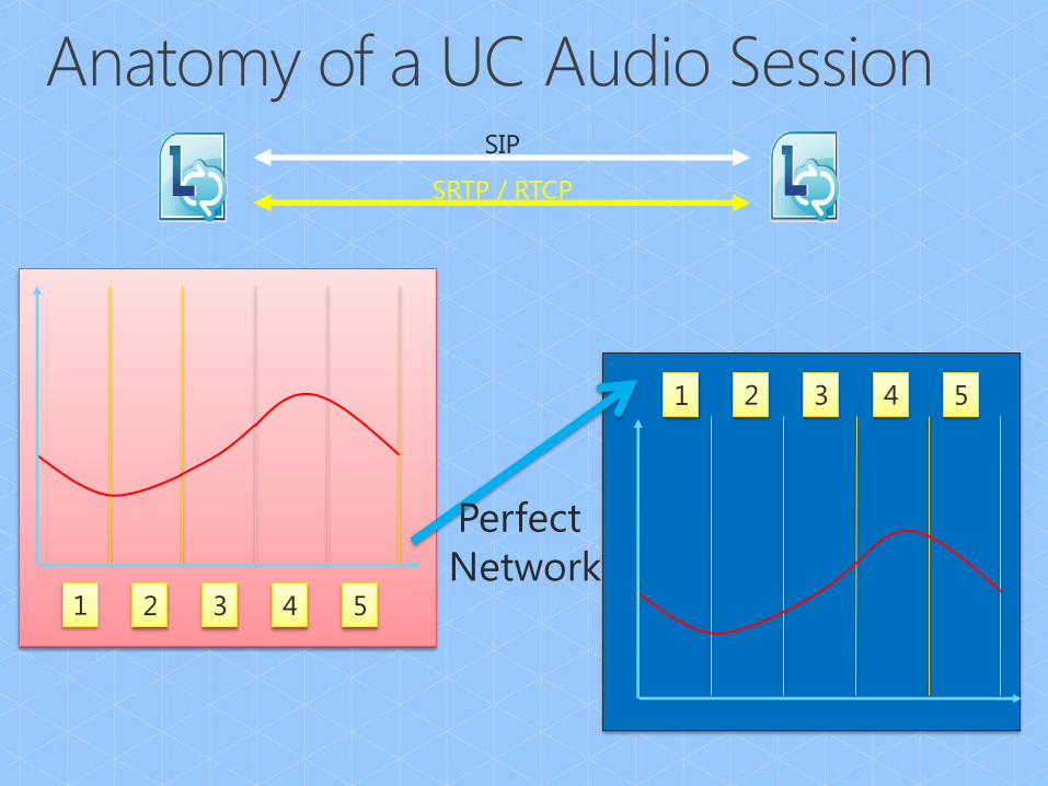
1 2 3 4 5
1 4 2 5 3
SRTP / RTCP
SIP
Perfect
Network

1 2 3 4 5
SRTP / RTCP
SIP

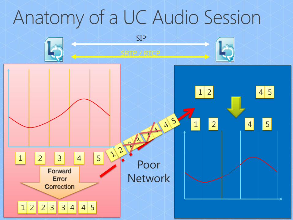
1 2 3 4 5 Poor
Network
SRTP / RTCP
SIP

1 2 3 4 2 3
Forward
Error
Correction
4 5
1 2 3 4 5 Poor
Network
SRTP / RTCP
SIP

1 2 3 4 2 3
Forward
Error
Correction
4 5
1 2 3 4 5 Poor
Network
SRTP / RTCP
SIP
1 2 3 4 2 3
Forward
Error
Correction
4 5
1 4 2 5
1 2 4 5
1 2 3 4 5 Poor
Network
SRTP / RTCP
SIP


Codec Scenario Payload Payload and
IP header
Payload, IP header,
and
UDP, RTP and SRTP
All that plus Forward
Error Correction (FEC)
RTA-WB Peer-to-peer 29.0 45.0 57.0 86.0
RTA-NB Peer-to-peer,
PSTN 11.8 27.8 39.8 51.6
G.711 PSTN 64.0 80.0 92.0 156.0
G.722 Conferencing 64.0 80.0 95.6 159.6
SIREN Conferencing 16.0 32.0 47.6 63.6
• These are raw audio codec bandwidth numbers – not for planning!
• All numbers in Kbps. Based on 20ms packetization time. Siren & G.722
include SRTP overheard from conferencing scenarios.

RT Video Codec
Resolution
Minimum payload
(kbps)
Maximum payload
(kbps)
Main Video CIF 50 250
Main Video VGA 350 600
Main Video HD 800 1500
Panoramic Video 50 350
• Raw video codec bandwidth numbers – not for planning!
• FEC built into the payload bitrate
• Maximum payload is the best possible frame rate & quality.
• Minimum is approximately 1 video frame per second.
• All numbers in Kbps. Based on 20ms ptime.
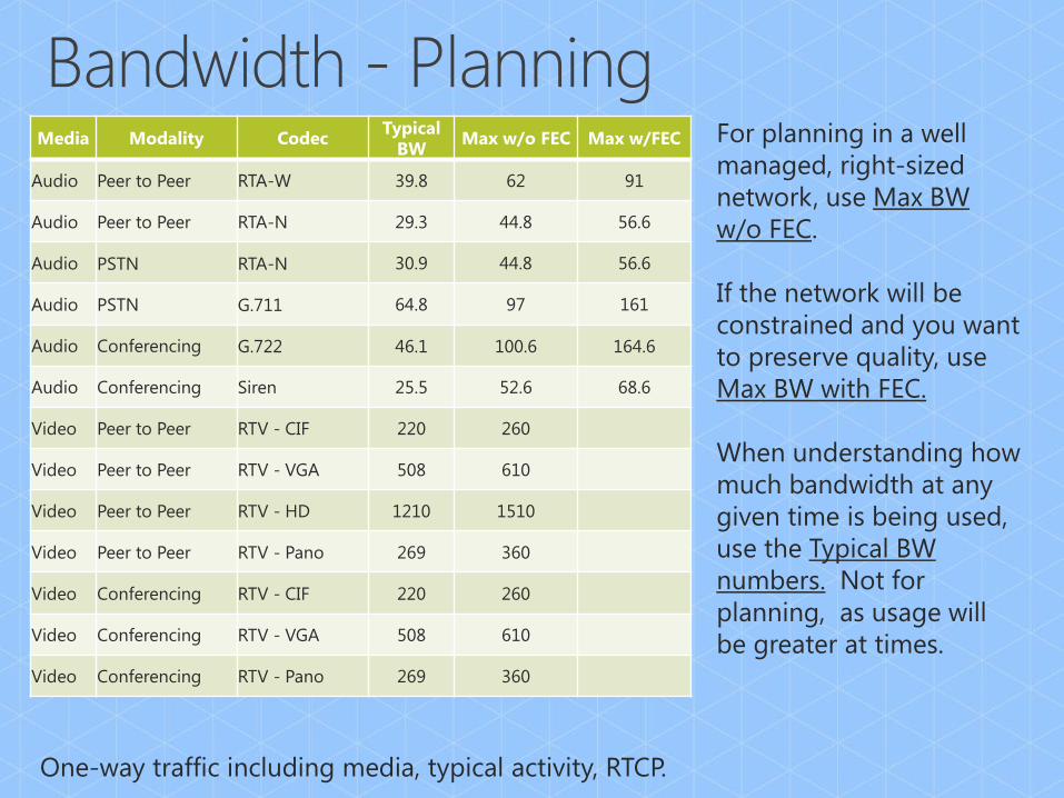
Media Modality Codec Typical
BW Max w/o FEC Max w/FEC
Audio Peer to Peer RTA-W 39.8 62 91
Audio Peer to Peer RTA-N 29.3 44.8 56.6
Audio PSTN RTA-N 30.9 44.8 56.6
Audio PSTN G.711 64.8 97 161
Audio Conferencing G.722 46.1 100.6 164.6
Audio Conferencing Siren 25.5 52.6 68.6
Video Peer to Peer RTV - CIF 220 260
Video Peer to Peer RTV - VGA 508 610
Video Peer to Peer RTV - HD 1210 1510
Video Peer to Peer RTV - Pano 269 360
Video Conferencing RTV - CIF 220 260
Video Conferencing RTV - VGA 508 610
Video Conferencing RTV - Pano 269 360
One-way traffic including media, typical activity, RTCP.
For planning in a well
managed, right-sized
network, use Max BW
w/o FEC.
If the network will be
constrained and you want
to preserve quality, use
Max BW with FEC.
When understanding how
much bandwidth at any
given time is being used,
use the Typical BW
numbers. Not for
planning, as usage will
be greater at times.
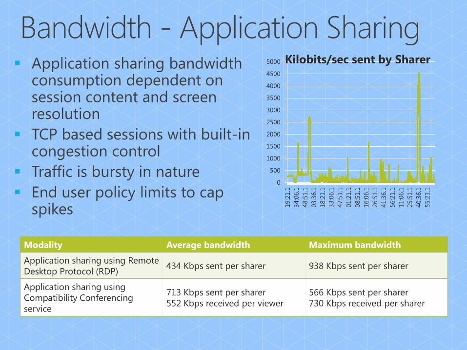
Modality Average bandwidth Maximum bandwidth
Application sharing using Remote
Desktop Protocol (RDP) 434 Kbps sent per sharer 938 Kbps sent per sharer
Application sharing using
Compatibility Conferencing
service
713 Kbps sent per sharer
552 Kbps received per viewer
566 Kbps sent per sharer
730 Kbps received per sharer
0
500
1000
1500
2000
2500
3000
3500
4000
4500
5000
19:2
1.1
34:0
6.1
48:5
1.1
03:3
6.1
18:2
1.1
33:0
6.1
47:5
1.1
01:2
1.1
08:5
1.1
16:0
6.1
26:5
1.1
41:3
6.1
56:2
1.1
11:0
6.1
25:5
1.1
40:3
6.1
55:2
1.1
Kilobits/sec sent by Sharer
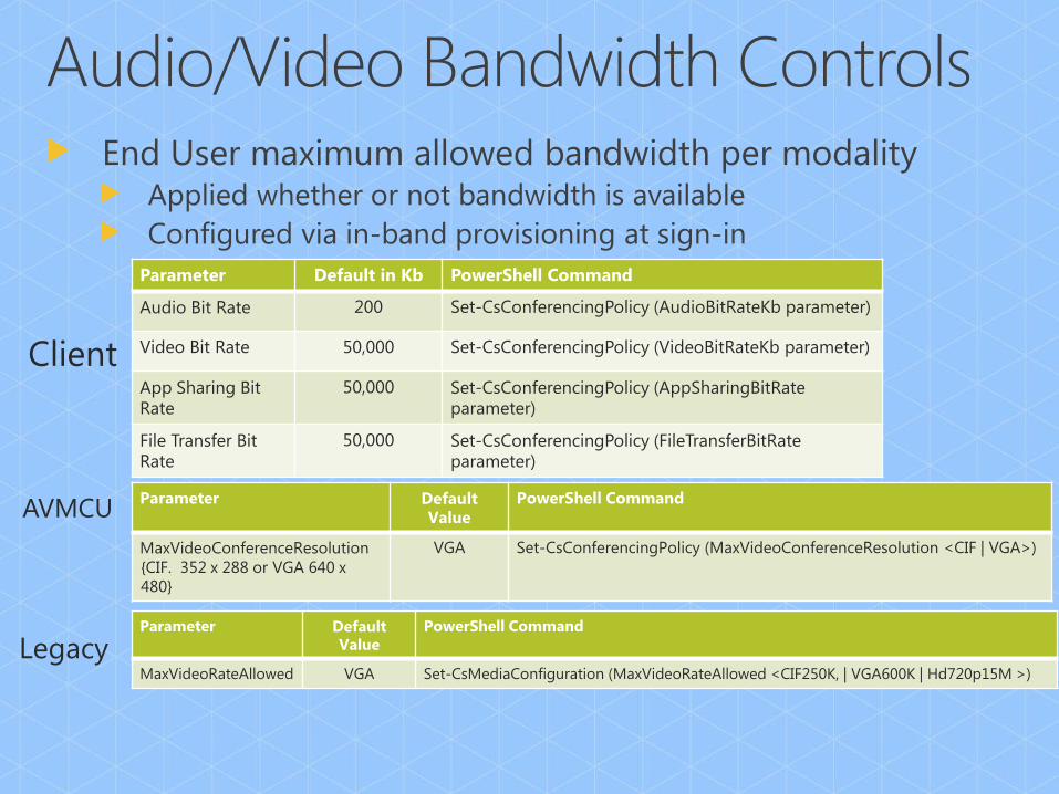
Parameter Default in Kb PowerShell Command
Audio Bit Rate 200 Set-CsConferencingPolicy (AudioBitRateKb parameter)
Video Bit Rate 50,000 Set-CsConferencingPolicy (VideoBitRateKb parameter)
App Sharing Bit Rate
50,000 Set-CsConferencingPolicy (AppSharingBitRate parameter)
File Transfer Bit Rate
50,000 Set-CsConferencingPolicy (FileTransferBitRate parameter)
Parameter Default
Value PowerShell Command
MaxVideoConferenceResolution
{CIF. 352 x 288 or VGA 640 x
480}
VGA Set-CsConferencingPolicy (MaxVideoConferenceResolution <CIF | VGA>)
Parameter Default Value
PowerShell Command
MaxVideoRateAllowed VGA Set-CsMediaConfiguration (MaxVideoRateAllowed <CIF250K, | VGA600K | Hd720p15M >)
Client
AVMCU
Legacy

Application
Presentation
Session
Transport
Network
Data Link
Physical Bandwidth
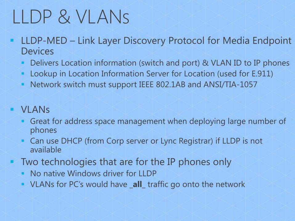
LLDP & VLANs

Application
Presentation
Session
Transport
Network
Data Link LLDP & VLANs
Physical Bandwidth
DSCP
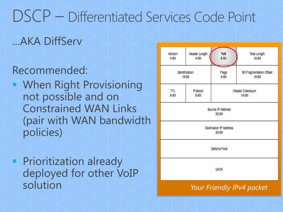
Your Friendly IPv4 packet

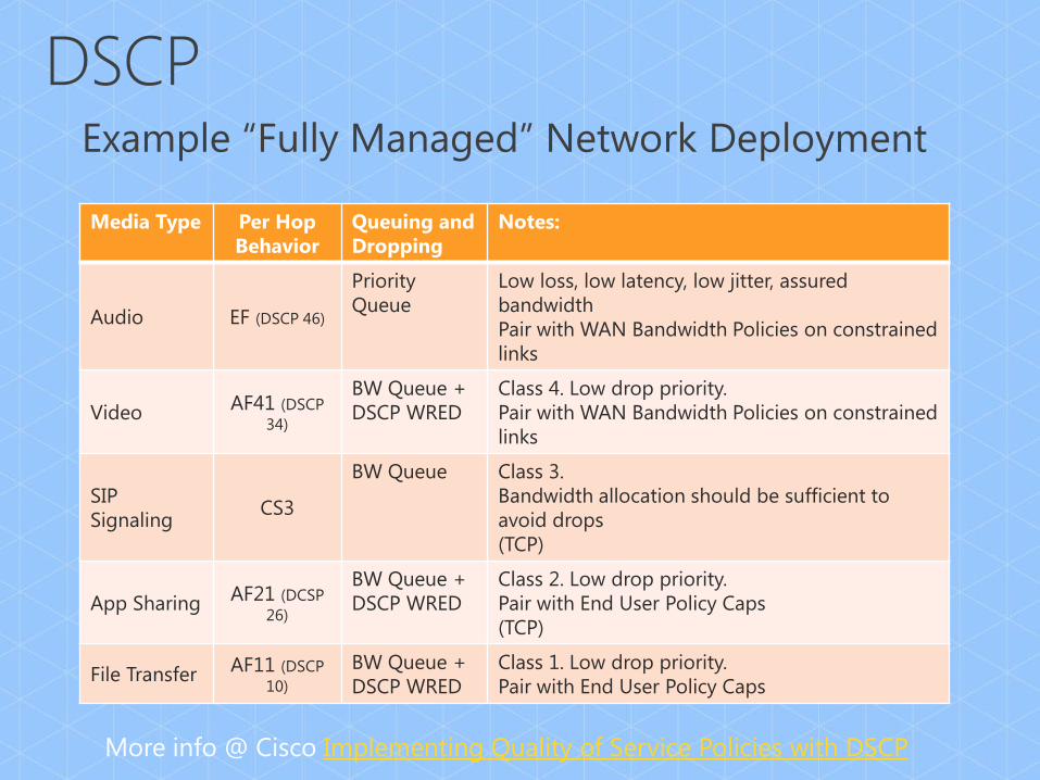
Media Type Per Hop
Behavior
Queuing and
Dropping
Notes:
Audio EF (DSCP 46)
Priority
Queue
Low loss, low latency, low jitter, assured
bandwidth
Pair with WAN Bandwidth Policies on constrained
links
Video AF41 (DSCP
34)
BW Queue +
DSCP WRED
Class 4. Low drop priority.
Pair with WAN Bandwidth Policies on constrained
links
SIP
Signaling CS3
BW Queue Class 3.
Bandwidth allocation should be sufficient to
avoid drops
(TCP)
App Sharing AF21 (DCSP
26)
BW Queue +
DSCP WRED
Class 2. Low drop priority.
Pair with End User Policy Caps
(TCP)
File Transfer AF11 (DSCP
10)
BW Queue +
DSCP WRED
Class 1. Low drop priority.
Pair with End User Policy Caps
More info @ Cisco Implementing Quality of Service Policies with DSCP
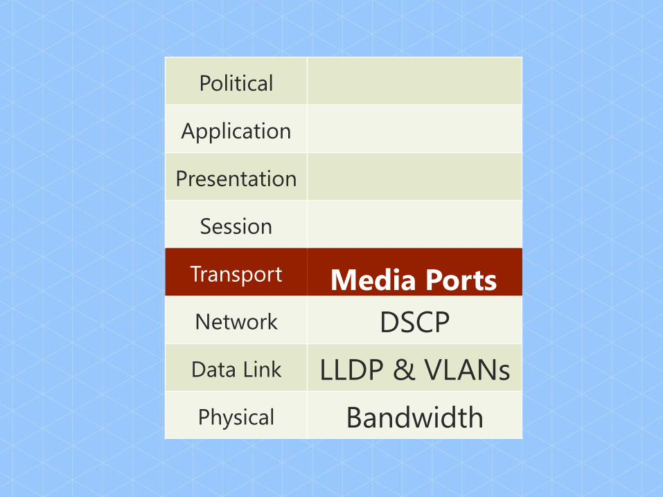
Political
Application
Presentation
Session
Transport
Network DSCP
Data Link LLDP & VLANs
Physical Bandwidth
Media Ports

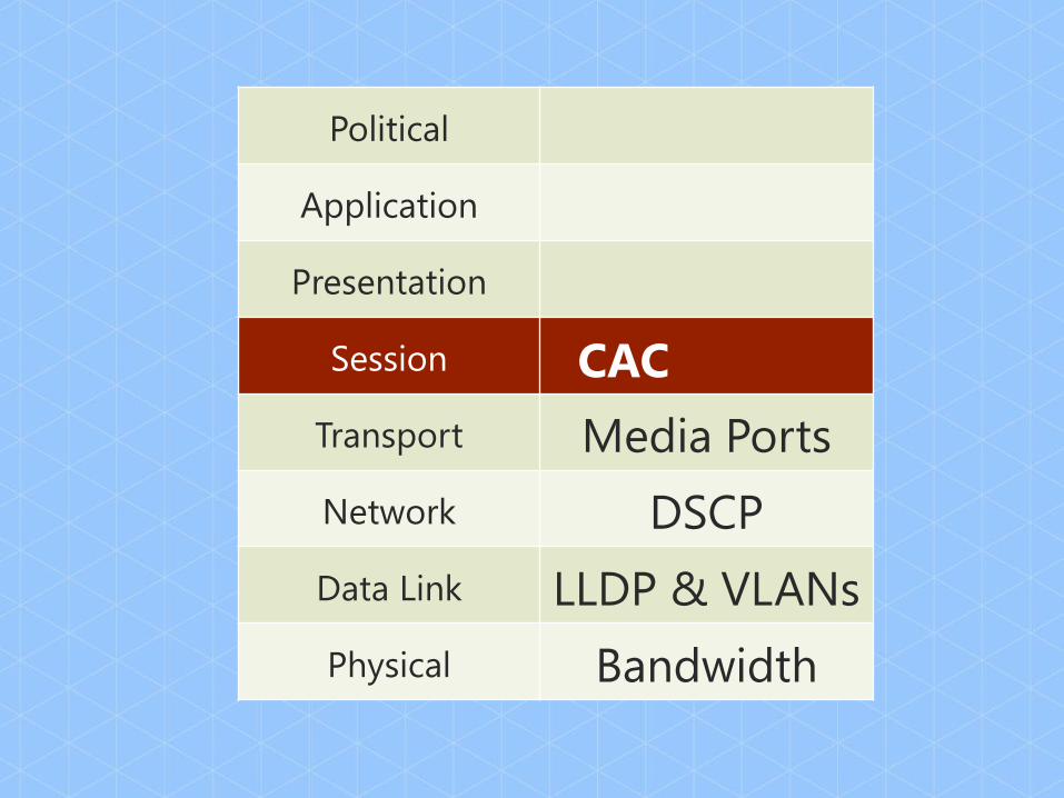
Political
Application
Presentation
Session
Transport Media Ports
Network DSCP
Data Link LLDP & VLANs
Physical Bandwidth
CAC
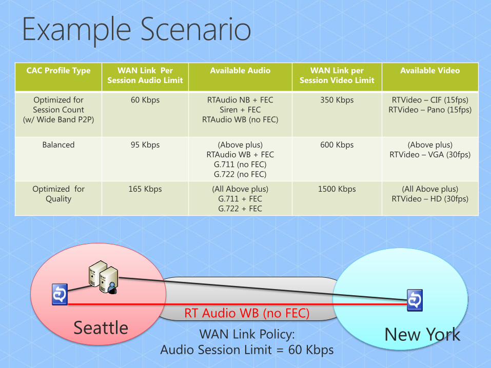
Seattle WAN Link Policy:
Audio Session Limit = 60 Kbps
RT Audio WB (no FEC)
CAC Profile Type WAN Link Per
Session Audio Limit
Available Audio WAN Link per
Session Video Limit
Available Video
Optimized for
Session Count
(w/ Wide Band P2P)
60 Kbps RTAudio NB + FEC
Siren + FEC
RTAudio WB (no FEC)
350 Kbps RTVideo – CIF (15fps)
RTVideo – Pano (15fps)
Balanced 95 Kbps (Above plus)
RTAudio WB + FEC
G.711 (no FEC)
G.722 (no FEC)
600 Kbps (Above plus)
RTVideo – VGA (30fps)
Optimized for
Quality
165 Kbps (All Above plus)
G.711 + FEC
G.722 + FEC
1500 Kbps (All Above plus)
RTVideo – HD (30fps)
New York

New York Seattle Internet
WAN Link Policy:
Audio Session Limit = 60 Kbps
RT Audio WB (No FEC)
CAC Profile Type WAN Link Per
Session Audio Limit
Available Audio WAN Link per
Session Video Limit
Available Video
Optimized for
Session Count
(w/ Wide Band P2P)
60 Kbps RTAudio NB + FEC
Siren + FEC
RTAudio WB (no FEC)
350 Kbps RTVideo – CIF (15fps)
RTVideo – Pano (15fps)
Balanced 95 Kbps (Above plus)
RTAudio WB + FEC
G.711 (no FEC)
G.722 (no FEC)
600 Kbps (Above plus)
RTVideo – VGA (30fps)
Optimized for
Quality
165 Kbps (All Above plus)
G.711 + FEC
G.722 + FEC
1500 Kbps (All Above plus)
RTVideo – HD (30fps)
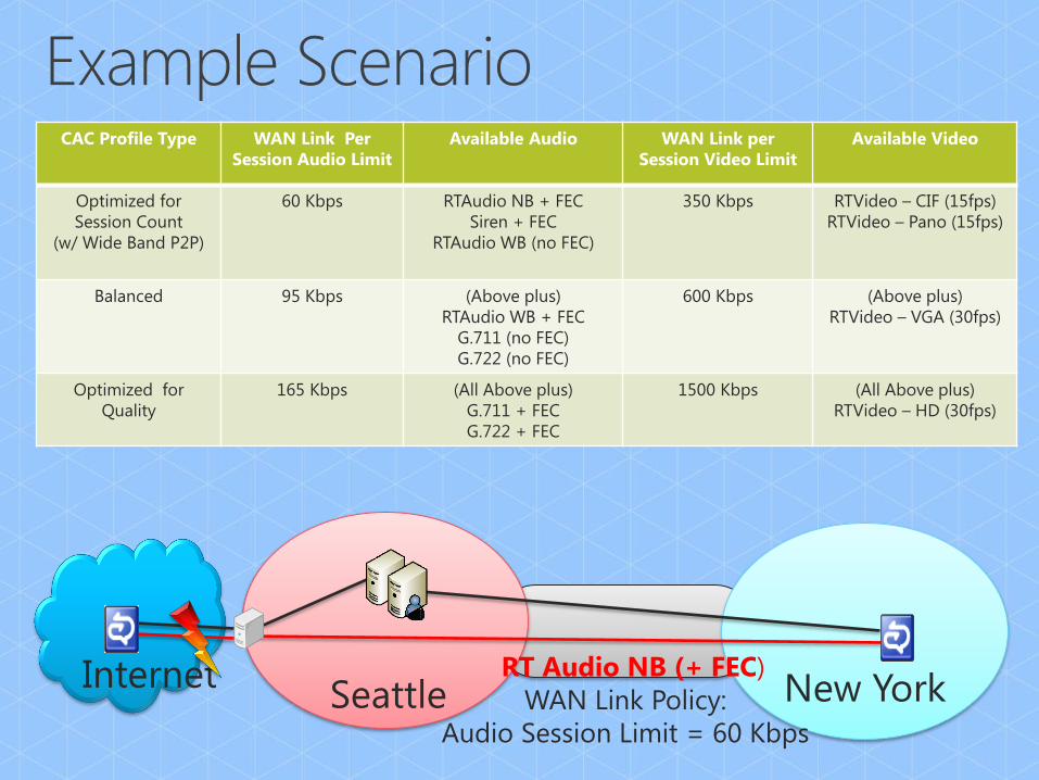
New York Seattle Internet
WAN Link Policy:
Audio Session Limit = 60 Kbps
RT Audio NB (+ FEC)
CAC Profile Type WAN Link Per
Session Audio Limit
Available Audio WAN Link per
Session Video Limit
Available Video
Optimized for
Session Count
(w/ Wide Band P2P)
60 Kbps RTAudio NB + FEC
Siren + FEC
RTAudio WB (no FEC)
350 Kbps RTVideo – CIF (15fps)
RTVideo – Pano (15fps)
Balanced 95 Kbps (Above plus)
RTAudio WB + FEC
G.711 (no FEC)
G.722 (no FEC)
600 Kbps (Above plus)
RTVideo – VGA (30fps)
Optimized for
Quality
165 Kbps (All Above plus)
G.711 + FEC
G.722 + FEC
1500 Kbps (All Above plus)
RTVideo – HD (30fps)
Application
Presentation
Session CAC
Transport Media Ports
Network DSCP
Data Link LLDP & VLANs
Physical Bandwidth
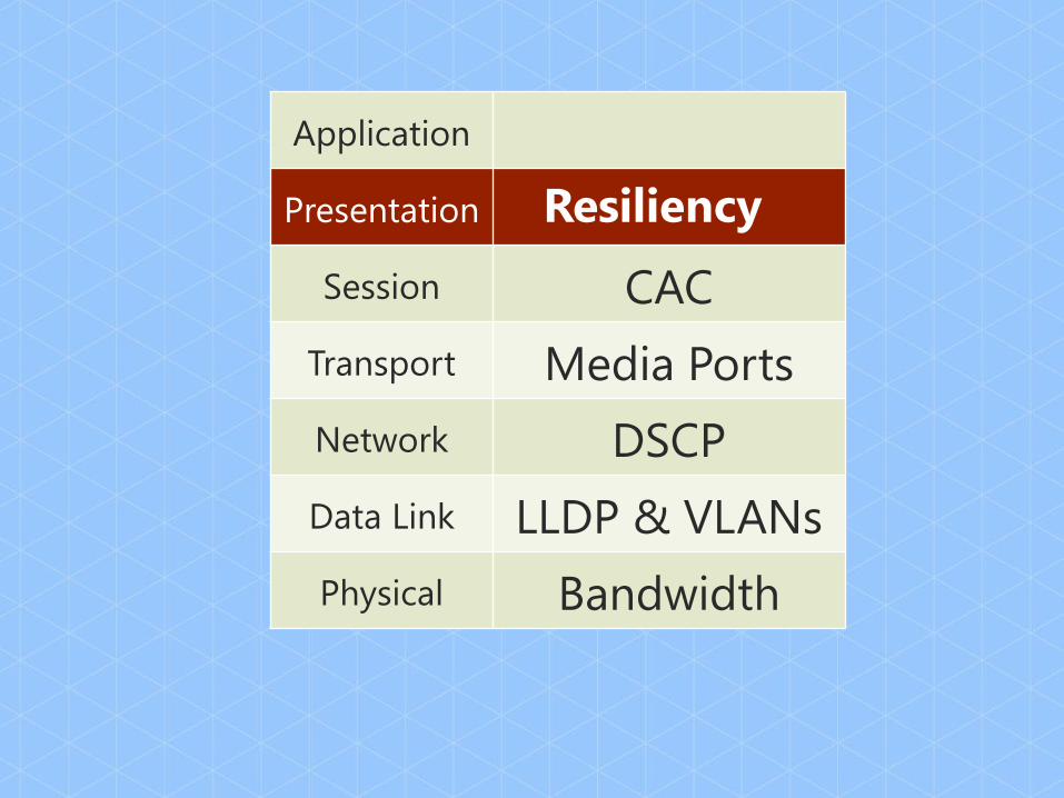
Resiliency
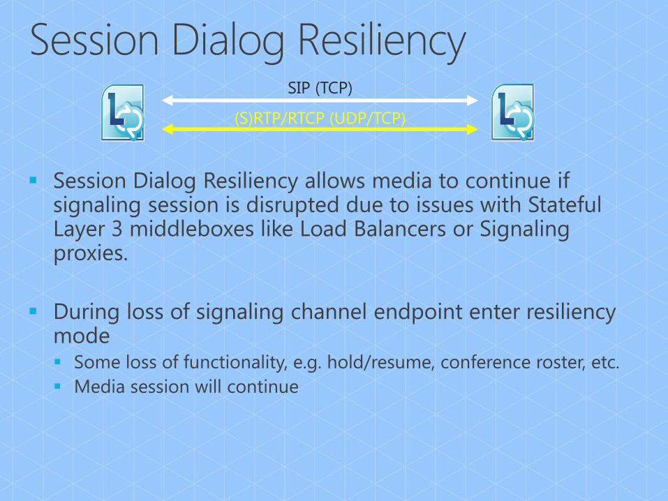
(S)RTP/RTCP (UDP/TCP)
SIP (TCP)

(S)RTP/RTCP (UDP/TCP)
SIP (TCP)

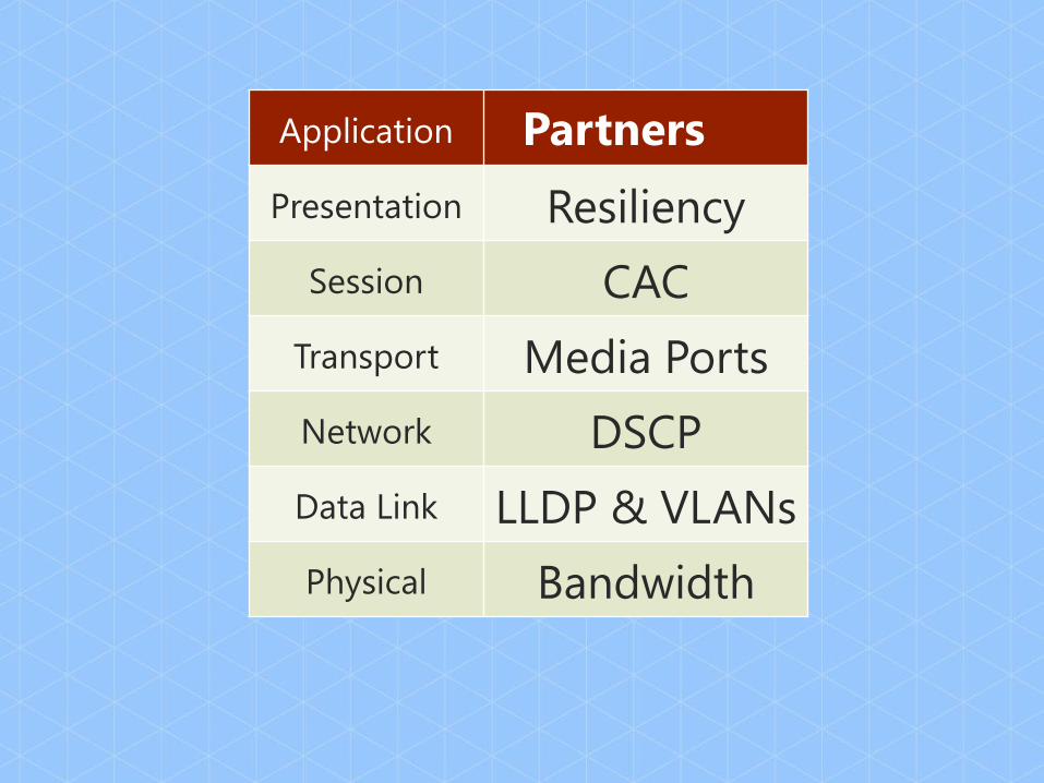
Application
Presentation Resiliency
Session CAC
Transport Media Ports
Network DSCP
Data Link LLDP & VLANs
Physical Bandwidth
Partners

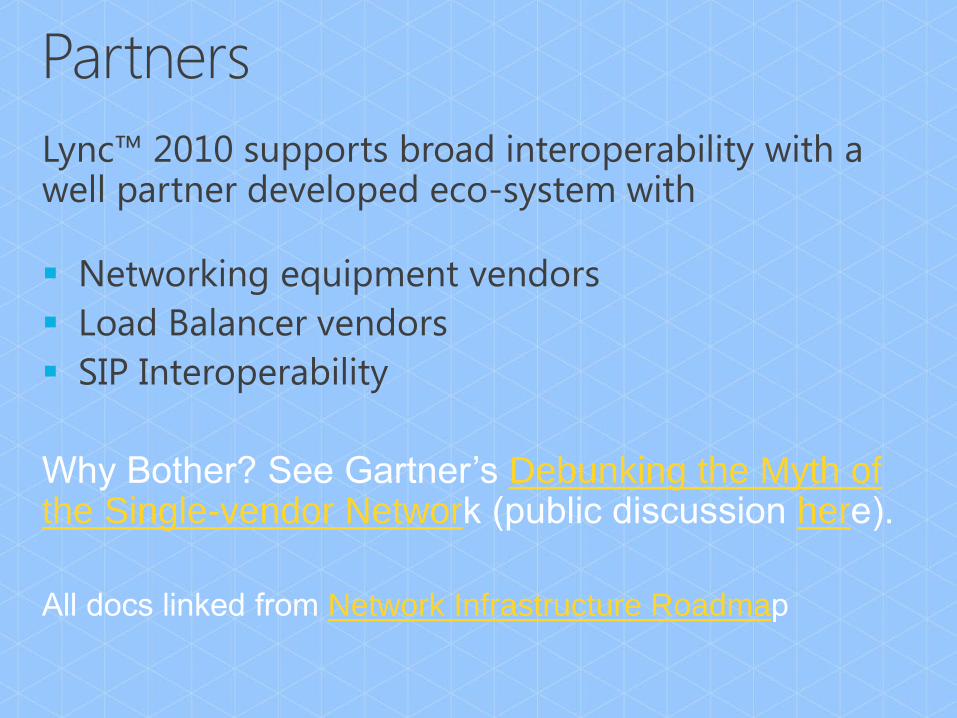
Debunking the Myth of the Single-vendor Networ her
Network Infrastructure Roadma

Partner OCS 2007 R2 Lync
HP Published Published
Juniper Published Published
Brocade Published Published
Cisco N/A Testing to start July
Aruba N/A Publishing June
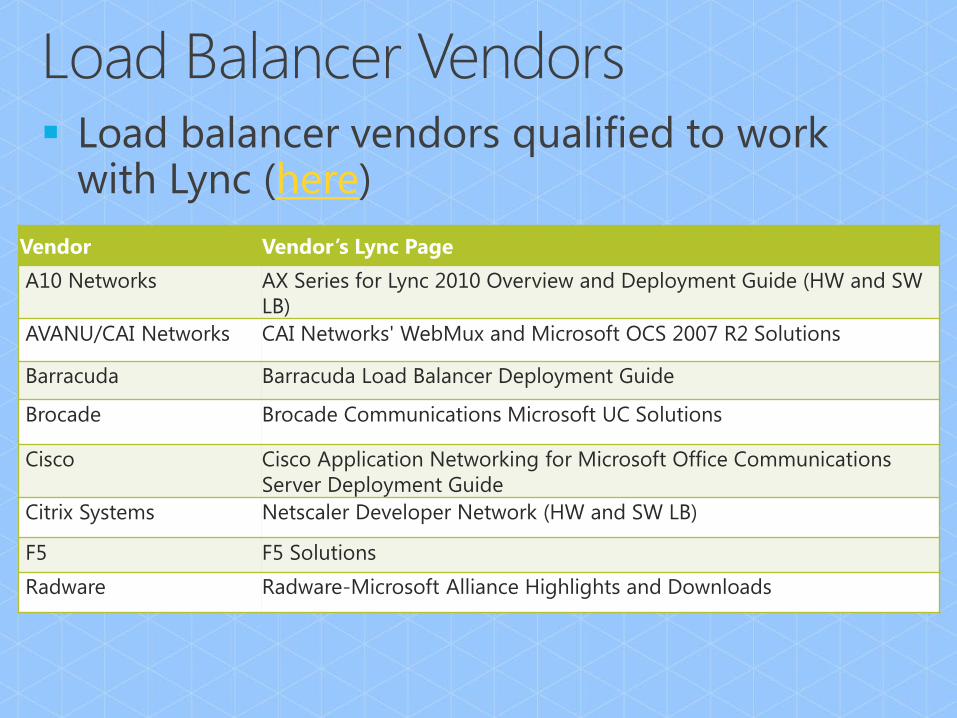
here
Vendor Vendor’s Lync Page
A10 Networks AX Series for Lync 2010 Overview and Deployment Guide (HW and SW
LB)
AVANU/CAI Networks CAI Networks' WebMux and Microsoft OCS 2007 R2 Solutions
Barracuda Barracuda Load Balancer Deployment Guide
Brocade Brocade Communications Microsoft UC Solutions
Cisco Cisco Application Networking for Microsoft Office Communications
Server Deployment Guide
Citrix Systems Netscaler Developer Network (HW and SW LB)
F5 F5 Solutions
Radware Radware-Microsoft Alliance Highlights and Downloads

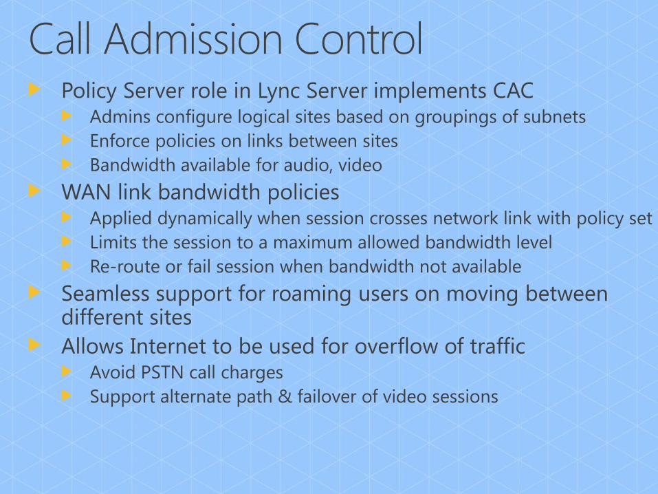
Partners Lync demonstrates broad open interoperability and adapts to
heterogenous networks
Resiliency Recovers from bad networking/glitches much better than
traditional hard-phone
CAC CAC + Adaptive Media Stack + Re-routing over the internet
Media Ports Optimize traffic at the workstation or the router. Separate traffic for
modalities
DSCP Mark the packets as they hit the wire from Lync clients
LLDP &
VLANs Working across heterogeneous network architectures
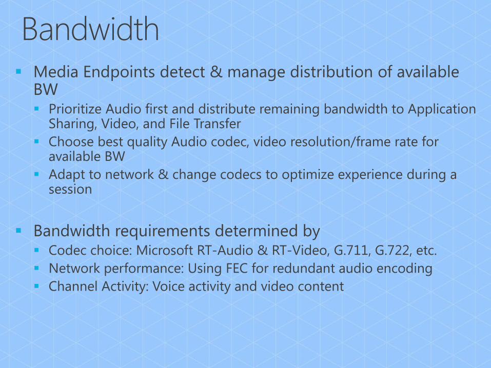
Bandwidth Better quality of experience on any network with smart endpoints,
management & monitoring across the network.