Embed Size (px)
Citation preview

LV-ECON
E Controller
Instructions
M374 E 07.1.NF.2 (2/3)


1
Thank you for purchasing the Nikon product.This instruction manual is written for the users of the Nikon LV-ECON E controller.To ensure correct usage, read this manual carefully before operating the product.
• It is prohibited to reproduce or transmit this manual in part or whole without Nikon’sexpressed permission.
• The contents of this manual are subject to change without notice.• Although every effort has been made to ensure the accuracy of this manual, if you
note any points that are unclear or incorrect, contact your nearest Nikonrepresentative.
• Some of the products described in this manual may not be included in the set youhave purchased.
• Also be sure to read the manuals for any other products that you are using with thissystem.
• If the products are used in a manner that is not described in this manual, the safety ofthe product may be adversely affected.
WARNING
CAUTION
WARNING and CAUTION Symbols Used in This Manual
Although this product is designed to provide the utmost safety during use, incorrectusage or failure to follow the safety instructions provided may cause personal injury orproperty damage. To ensure correct usage, read the instruction manual carefully andthoroughly before using the product. Do not discard the manual; keep it handy for easyreference.Safety instructions within this manual are accompanied by the following symbols tohighlight their importance. For your safety, always follow the instructionsaccompanying these symbols.
Symbol Meaning
Disregarding instructions accompanying this symbol maylead to serious injury or death.
Disregarding instructions accompanying this symbol maylead to injury or property damage.

2
Meaning of the Symbol Used on the Product
Symbol Meaning
Caution for heatThe symbol is indicated on the following places: near thelamp house clamp screw of the LV-UEPI, LV-UEPI2, andLV-UEPI2A illuminator, on the back of the lamp houses, andnear the lamp replace cover plate and above the air vent onthe back of the C-HGFIE precentered fiber illuminator. Theycall your attention on the following. For positions of thesymbol, refer to the instructions manual of the illuminator.• The lamp house become extremely hot while the lamp is on
and immediately after it is turned off.• Do not touch the lamp house during and immediately after
lighting to prevent the risk of burns.• Make sure that the lamp house is sufficiently cool before
the lamp replacement.• Do not allow cloths, papers, or highly flammable volatile
materials, such as gasoline, benzine, thinner or alcohol, tocome near the lamp house, illuminator, or their surroundingareas while the lamp is lit or within 30 minutes after thelamp is turned off.
• Do not allow walls, curtains, or papers to contact theproduct.
• Keep hands away from the air vent of the C-HGFIEprecentered fiber illuminator when the lamp is lit. Do noblock the airflow from the air vent.
CautionThe symbol is indicated on the following places: near thelamp replace cover plate on the top and above the air vent onthe back of the C-HGFIE precentered fiber illuminator. Theycall your attention on the following. For positions of thesymbol, refer to the instructions manual of the illuminator.• Before replacing the lamp, turn off the illuminator and
unplug the power cord.• Read the instructions manual carefully for replacing the
lamp.
Do not touch when carrying the product.The symbols on the both sides of the LV-FMA motorizedfocusing module call your attention on the following. You cansee the positions of this symbol on Page 16.• Do not touch the elevating section and arm when carrying
this product.

3
WARNING
1. Intended product useThis product is used to control the various motorized devices of Nikon LV series products,the specified power supply for the illuminator, and the external light source. Do not use thisproduct for other purpose.
2. Do not disassembleDisassembling this product may result in electric shock or malfunctions. Never attempt todisassemble any part other than the parts described in this manual. If you experienceproblems with this product, contact your nearest Nikon representative.
3. Read the instructions carefullyTo ensure safety, carefully read this manual and the manuals for other equipment used withthis product. In particular, observe all warnings and cautions given at the beginning of eachmanual.
Operation for the light sourceWhen an external light source, such as a mercury lamp or a xenon lamp, is used, you musttake great care of the lamp Read the instruction manual for the light source and follow theinstructions and cautions for it.
4. Ratings of the power supplyThe power supply circuit in this product is designed for AC power of 100 to 240 VAC and50/60 Hz. Before connecting the power cord, check that the power supply to be usedconforms to the voltage and frequency described above. Use of a non-conforming powerline may result in equipment malfunction, failure, or fire.
5. Power cordMake sure to use the specified power cord. Using a wrong power cord may result inmalfunctions or fire. The product is classified as subject to Class I protection againstelectrical shock. Make sure it is connected to an appropriate ground terminal (protectiveearth terminal). To prevent electrical shock, always turn off the power switch (press it to the“O” position) for the product before attaching or detaching the power cord. Forspecifications of the power cord, refer to “VII. Specifications.”
6. Object devices of this productThis product can be used with devices described below. But this cannot be used with otherdevices.
• Motorized nosepiece: LV-NU5A motorized universal quintuple nosepiece ESD,LV-NU5AC motorized universal quintuple centerable nosepiece
• Motorized DIC nosepiece: LV-MDIC motorized DIC module• Motorized epi illuminator: LV-UEPI2A motorized universal epi illuminator 2A• Motorized focusing module: LV-FMA FM module A (motorized drive),
LV-IMA IM module A (motorized drive)• Auto focus system: LV-AF auto focus• Power supply for the lamp: TE2-PS100W power supply• LED epi illuminator: LV-EPILED epi illuminator LED• External light source: C-HGFIE Intensilight (precentered fiber illuminator)
EXFO X-Cite 120 PC• PC: Windows PC with an USB interface

4
WARNING
7. Handling of the motorized devices and the light source• Each motorized device will move when this product is operated. To prevent injury, do not
touch the moving device during operation. Before operating this product, check allmoving devices for your safety.
• If you touch the elevating section or its attached devices during operation of the motorizedfocusing module, it may cause injury to hands or fingers. Do not touch the motorizeddevices when you operate the product.
• When a power supply for the illuminator or an external light source is connected with thisproduct, you can control the lamp and shutter with operating this product. Beforeoperating this product, check the illuminator and its surroundings for your safety.
8. Heat from the light sourceThe lamp, the lamp house, and the illuminator become extremely hot. To avoid burns, donot touch the devices while the lamp is lit or for thirty minutes after it is turned off.Furthermore, to avoid the risk of fire, do not place fabric, paper, or highly flammablevolatile materials (such as gasoline, petroleum benzine, paint thinner, or alcohol) near thedevices while the lamp is lit or for about thirty minutes after it is turned off.
9. Cooling fan and air ventsDo not block the opening for the cooling fan on the back and air vents on the side. If thecooling fan or air vents are blocked, the temperature of the product will rise. And it resultsin a malfunction, damage, or fire.
CAUTION
1. Handle with care• Handle this product with care to avoid shock on impact.• Do not forcefully bend, pull or twist the power cord and the cables.• Do not drop metal pieces such as clips and staples through any clearance into the product
inside. It could cause a failure of the product or a fire.
2. Do not wet the productIf the product gets wet, a short circuit may cause malfunction or abnormal heating of theproduct. If you accidentally spill water on the product, immediately turn off the powerswitch (flip it to the “ ” side) and unplug the power cord from the wall outlet. Then, wipeoff the water with a piece of dry cloth. If water enters a component, immediately suspenduse of this product, disconnect the power cord from the outlet, and contact your nearestNikon representative.
3. Weak electromagnetic wavesThe product emits weak electromagnetic waves. There is a possibility that some precisionelectronic devices are affected by the electromagnetic waves. To prevent bad influences,locate such electronic equipment away from this product. If a TV or radio reception isaffected, move the TV or radio set farther from the product.

5
CAUTION
4. Installation locationIf this product is used or stored in an inappropriate environment, malfunctions or poorperformance may arise for it. Consider the following factors when selecting an installationlocation:• Avoid a brightly lit location, such as exposed to direct sunlight or directly under a room
light. If there is excessive ambient light, the image quality deteriorates.• Always install the devices with a surrounding clear area of 10 cm or more.• Choose a location that is free from considerable dust or dirt.• Choose a flat surface with little vibration.• Choose a sturdy desk or table for the base of the microscope system.• Do not install the microscope in a hot and humid location.• Select a layout that allows easy removal of the power cord from the product’s AC inlet in
the event of an emergency.• For details about the operating environment and storage environment, see “VII.
Specifications.”
5. Cautions on assembling this product• Always turn off the power switch before assembling the product, connecting or
disconnecting cords, or lamp replacement.• Be careful not to pinch your fingers or hands during assembly.• Scratches or fingerprints on the lenses will adversely affect the image. Be careful not to
scratch or touch the lens surfaces.
6. Cable routingMake sure the cables are routed properly. Do not bring the cables into contact with the lamphouse and the illuminator. If a cable comes into contact with the lamp house or theilluminator, the cable sheath may melt and it results in an electrical shock or fire.
7. Cautions when replacing lamps• For details about replacement method for lamps, refer to the instruction manual for the epi
illuminator (LV-UEPI, LV-UEPI2, or LV-UEPI2A) or the precentered fiber illuminator(C-HGFIE). Carefully read the instruction manuals for the illuminator, and then follow theinstructions to replace lamps.
• To prevent burn injuries, wait at least 30 minutes after the lamp is turned off to give itsufficient time to cool down when replacing lamps.
• To prevent electrical shock and damage to the product, always turn off the power switch(flip it to the “ ” side) and unplug the power cord from the outlet before attaching ordetaching the lamp house.
• Never touch the glass surface of the lamp with bare hands. Doing so will causefingerprints, grease, etc. to burn onto the lamp surface, reducing the illumination. If youdo get any fingerprints or dirt on the lamp, wipe them clean.
• Make sure the lamp house cover is securely fitted to the lamp house after replacing lamps.Never turn on the lamp with the lamp house cover removed.
• When you dispose of the replaced lamp, do not break it up. Instead, dispose of the usedlamp as special industrial waste or dispose of it according to the local regulations and rules.
8. Software setup works after assemblyWhen the microscope is assembled or the configuration of the microscope is changed,perform the software setup works for various settings of the microscope via a PC by usingthe software, “LVSetup,” in “LV Series Support Tools” provided with this product.In the setup works, information for the devices and parts (objectives, filter cubes,illuminator, and so on) is registered and interlock controls for such devices are specified.Make sure to perform the setup works to use the microscope system correctly.For details about operations and setup works of “LVSetup,” see “LV Series Support Toolssoftware manual.”

6
CONTENTS
Warning/Caution Symbols Used in This Manual .............................................. 1Meaning of the Symbol Used on the Product .................................................. 2
WARNING ........................................................................................................ 3CAUTION.......................................................................................................... 4
Overview of the Product ............................................................................. 7
Names and Functions of Component Parts .............................................. 81 Operation Panel ................................................................................................................. 82 Connctor Panel .................................................................................................................. 9
Device Connections .................................................................................. 101 To Connect with the Motorized Nosepiece ..................................................................... 132 To Attach and Connect with the Motorized DIC Module (Nosepiece) ........................... 143 To Connect with the Motorized Focusing Module .......................................................... 164 To Connect with the Motorized Epi Illuminator ............................................................. 175 To Connect with the Episcopic Illumination ................................................................... 186 To Connect with the Light Source for the Diascopic Illumination ................................. 217 To Connect with the Auto Focus System ........................................................................ 228 To connect with a PC....................................................................................................... 249 To Connect with the DS-L2............................................................................................. 25
10 Power Cord Connection .................................................................................................. 2611 Tilt Adjustment Legs ....................................................................................................... 26
Operation.................................................................................................... 27
1 Power On/Off .................................................................................................................. 282 Setting Up the Microscope System ................................................................................. 293 Set-up Memory Operation ............................................................................................... 304 Selecting the Microscopy Method ................................................................................... 325 Operation for the Aperture Diaphragm for the Episcopic Illumination .......................... 346 Changing Objectives ....................................................................................................... 357 Operation for the Motorized Focusing Module ............................................................... 368 Operation for the DIC Prism ........................................................................................... 379 Operation for the Illumination ......................................................................................... 38
Troubleshooting......................................................................................... 41
Care and Maintenance .............................................................................. 431 Cleaning Lenses and Filters ............................................................................................ 442 Cleaning the Painted Parts, Plastic Parts, and Printed Parts ............................................ 443 Storage ............................................................................................................................. 444 Regular Inspections ......................................................................................................... 44
Specifications ............................................................................................ 45

7
Overview of the Product
The Nikon LV-ECON E controller is a device to control the microscopy system totally with variousmotorized devices for the LV series products, the external power supply for the illuminator, and theexternal light source.
This product can be used with devices described below.
• Motorized nosepiece (LV-NU5A or LV-NU5AC) *1
• Motorized DIC nosepiece (LV-MDIC) *1
• Motorized focusing module (LV-FMA or LV-IMA)• Motorized epi illuminator (LV-UEPI2A)• Epi illuminator LED (LV-EPILED) *2
• Halogen lamp power supply for the episcopic illumination (TE2-PS100W) *2
• External light source for the episcopic illumination (C-HGFIE or EXFO X-Cite 120 PC) *2
• Halogen lamp power supply for the diascopic illumination (TE2-PS100W)• Auto focus system (LV-AF)
*1 The motorized nosepiece and the motorizedDIC nosepiece cannot be used together.
*2 These devices cannot be used at a time.
INTENSILIGHTC-HGFIE
LAMP
POWER
RUN TIME hrs.
LV-DICANOSEPIECE
Do not touch the he igh t ad jus tment par t
when car r y ing th is produc t .
F.STOP
JAPAN
BF DF FL1 FL2
FL1 FL2
MODEL LV-ECONMADE IN JAPAN
1 2 2 0 0 1
This Class A digital apparatus complies with Canadian ICES-003.
Cet appareil numérique de la classe A est confirme à la norme NMB-003 du Canada.This device complies with Part 15 of the FCC Rules.Operation is subject to the
following two conditions:
(1)this device may not cause harmful interference, and
(2)this device must accept any interference received, including interference
that may cause undesired operation.
4N75
INSPECTION
EQUIPMENT
100–240V~ 1.0A 50/60Hz
NO.
CAUTIONLED RADIATION WHEN OPEN.
AVOIF EXPOSURE TO BEAM.
CLASS 3b LED
V o r s i c h t
u n s i c h t b a r e L E D S t r a h l u n g ,
w e n n A b d e c k u n g g e o f f n e t .
N i c h t d e m S t r a h l a u s s e t z e n .
L E D K l a s s e 3 b
MODEL LV-AFMADE IN JAPAN
3 2 2 1 0 1
This Class A digital apparatus complies with Canadian ICES-003.
Cet appareil numérique de la classe A est confirme à la norme NMB-003 du Canada.This device complies with Part 15 of the FCC Rules.Operation is subject to the
following two conditions:
(1) this device may not cause harmful interference, and
(2) this device must accept any interference received, including interference
that may cause undesired operation.
100–240V~ 1.0A 50/60Hz
NO.
POWER
MIN.
MAX.
POWER
MIN.
MAX.
LV-EPILEDJAPAN
JAPAN
EXT-INEXT
CONTROLDC-IN
OFFON
POWERLED
MINMAX
POWER
LV-FMA
LV-LH50PC
TE2-PS100W
LV-LH50PC
TE2-PS100W
LV-UEPI2A
LV-ECON
C-HGFIE or EXFO X-Cite 120 PC
LV-EPILED
LV-IMA
Digital camera for the microscope and the camera control unit
Motorized epi illuminator
Auto focus system
LV-AF
LV-MDIC
DS-L2 or such
DS-Fi1 or such
Motorized focus module
LV-NU5A orLV-NU5AC
Motorized nosepiece
Motorized DIC nosepiece
or
(One of these illuminators can be connected.)
Episcopic illumination
Diascopic illumination
For setup operation
PC

8
Names and Functions of Component Parts
1
10 10
5
8
2
3
4
6
7
9
1 Operation Panel
1 POWER indicator (green)It turns on green when the product is energized.
2 SET UP controlsThey are used to change the microscopy conditions to the user defined conditions specifiedwith ”LVSetup.”
3 Episcopic illumination controlsThey are used to turn on or turn off the episcopic illumination and to adjust the brightness.
4 Diascopic illumination controlsThey are used to turn on or turn off the diascopic illumination and to adjust the brightness.
5 FOCUS controlsThey are used to adjust the vertical position of the motorized focus module.
6 DIC controlsThey are used to change the position of the DIC prism (Nomarski prism) of the motorized DICnosepiece.
7 CUBE controlsThey are used to change microscopy methods by rotating the filter cube turret in the motorizedepi illuminator.
8 A.S. controlsThey are used to adjust the aperture diaphragm in the motorized epi illuminator.
9 OBJ. controlsThey are used to change objectives by rotating the motorized nosepiece.
10 Tilt adjustment legsThey are used to adjust the tilt angle of the product.

9
DIA EPIC-HGFIE
USB
LV-AF TE2-PS100W TE2-PS100W
UEPI2A
100-240V~ 1.0A 50/60Hz
LV-FMA LV-DICA
NOSEPIECE
11 12 13 14
2220 21
15
16
17
18
19
2 Connector Panel
11 C-HGFIE connectorAn external light source (Nikon C-HGFIE or EXFO X-Cite 120 PC) is connected here.
12 LV-AF connectorThe auto focus controller (Nikon LV-AF) is connected here.
13 DIA TE2-PS100W connectorThe halogen lamp power supply for the diascopic illumination (Nikon TE2-PS100W) isconnected here.
14 EPI TE2-PS100W connectorThe halogen lamp power supply for the episcopic illumination (Nikon TE2-PS100W) or LEDepi illuminator (Nikon LV-EPILED) is connected here.
15 USB connectorA PC is connected here for set-up works. (It is complies with USB 1.1.)
16 LV-UPI2A connectorThe motorized epi illuminator (Nikon LV-UEPI2A) is connected here.
17 LV-FMA connectorThe motorized focusing module (Nikon LV-FMA or LV-IMA) is connected here.
18 LV-DICA connectorThe DIC prism control cable of the motorized DIC nosepiece (LV-MDIC) is connected here.
19 NOSEPIECE connectorThe nosepiece control cable of the motorized nosepiece (Nikon LV-NU5A or LV-NU5AC) orof the motorized DIC nosepiece (LV-MDIC) is connected here.
20 Power switchThis is the power switch of this product.
21 AC inletThe AC power supply is connected here. Make sure to use the specified power cord.
22 Cooling fanThis is the cooling fan of this product.
II. Names and Functions of Component Parts
10
Device Connections
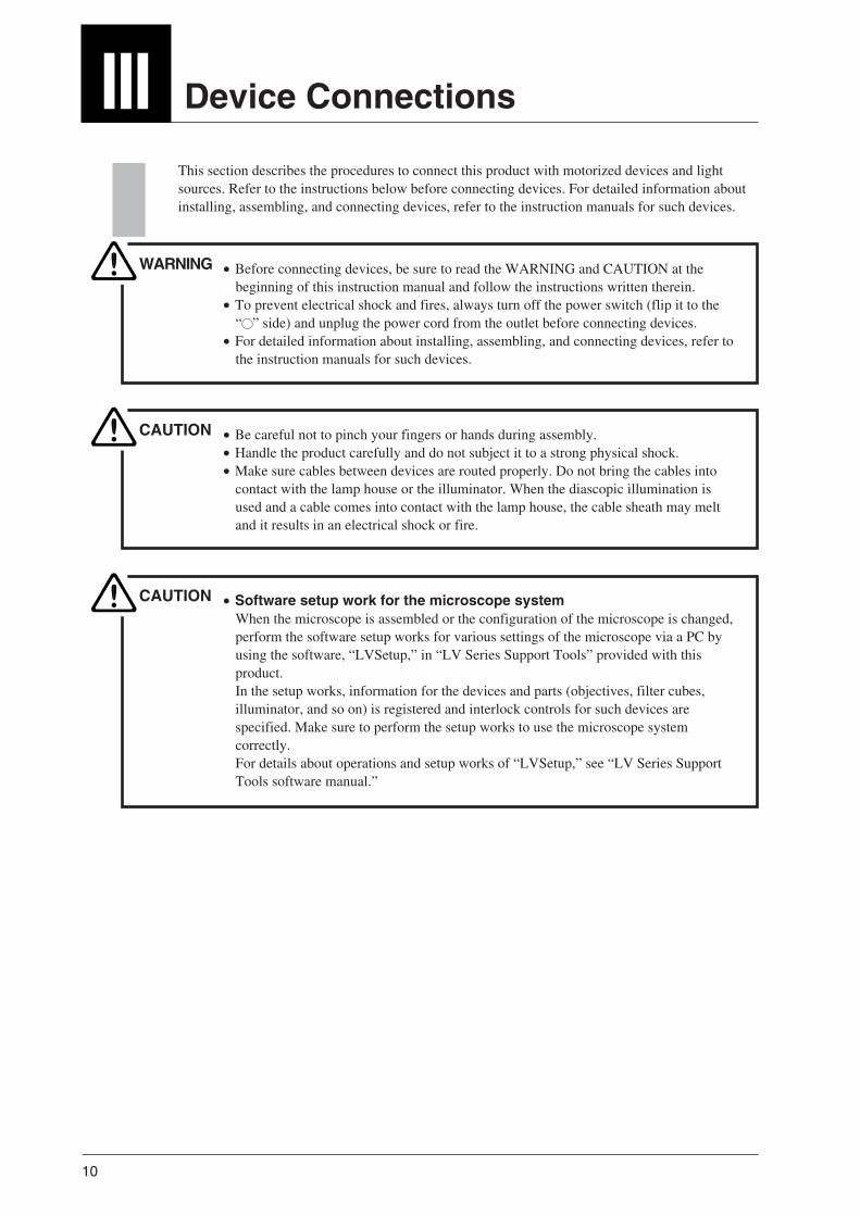
This section describes the procedures to connect this product with motorized devices and lightsources. Refer to the instructions below before connecting devices. For detailed information aboutinstalling, assembling, and connecting devices, refer to the instruction manuals for such devices.
WARNING • Before connecting devices, be sure to read the WARNING and CAUTION at thebeginning of this instruction manual and follow the instructions written therein.
• To prevent electrical shock and fires, always turn off the power switch (flip it to the“ ” side) and unplug the power cord from the outlet before connecting devices.
• For detailed information about installing, assembling, and connecting devices, refer tothe instruction manuals for such devices.
CAUTION • Be careful not to pinch your fingers or hands during assembly.• Handle the product carefully and do not subject it to a strong physical shock.• Make sure cables between devices are routed properly. Do not bring the cables into
contact with the lamp house or the illuminator. When the diascopic illumination isused and a cable comes into contact with the lamp house, the cable sheath may meltand it results in an electrical shock or fire.
CAUTION • Software setup work for the microscope systemWhen the microscope is assembled or the configuration of the microscope is changed,perform the software setup works for various settings of the microscope via a PC byusing the software, “LVSetup,” in “LV Series Support Tools” provided with thisproduct.In the setup works, information for the devices and parts (objectives, filter cubes,illuminator, and so on) is registered and interlock controls for such devices arespecified. Make sure to perform the setup works to use the microscope systemcorrectly.For details about operations and setup works of “LVSetup,” see “LV Series SupportTools software manual.”

11
III. Device Connections
ND8 NCB
F.S.
10020
0100IN
OUT
LV-TT2
JAPAN
INTENSILIGHTC-HGFIE
LAMP
POWER
RUN TIME hrs.
Do not touch the he igh t ad jus tment par t
when car r y ing th is produc t .
F.STOP
JAPAN
BF DF FL1 FL2
FL1 FL2
MODEL LV-ECONMADE IN JAPAN
1 2 2 0 0 1
This Class A digital apparatus complies with Canadian ICES-003.
Cet appareil numérique de la classe A est confirme à la norme NMB-003 du Canada.This device complies with Part 15 of the FCC Rules.Operation is subject to the
following two conditions:
(1)this device may not cause harmful interference, and
(2)this device must accept any interference received, including interference
that may cause undesired operation.
4N75
INSPECTION
EQUIPMENT
100–240V~ 1.0A 50/60Hz
NO.
POWER
MIN.
MAX.
POWER
MIN.
MAX.
Motorizedfocusing moduleLV-FMA *2
Eyepiece tubeLV-TT2
Either device
Motorized nosepiece *2
LV-NU5A
Lamp house for the episcopic illuminationLV-LH50PC *1
Power supplyTE2-PS100W *1
Lamp house for the diascopic illuminationLV-LH50PC
Power supplyTE2-PS100W *1
Microscope baseLV-DIA or LV-EPI
For LV-DIA
Motorized epi illuminatorLV-UEPI2A
PC *1 *3
E controllerLV-ECON *1
External light sourceC-HGFIE *1
Fiber adapterLV-HGFA
*1 : This device needs a power supply for its own.
*2 : To use the motorized DIC nosepiece, remove the arm of the LV-FMA and attach the LV-MDIC in place.*3 : A camera control unit such as DS-L2 can be used in place of the PC for control of each unit. (To set up the
system configuration, a PC must be used.)
Example 1 (configuration with the LV-FMA)

12
MODEL LV-ECONMADE IN JAPAN
1 2 2 0 0 1
This Class A digital apparatus complies with Canadian ICES-003.
Cet appareil numérique de la classe A est confirme à la norme NMB-003 du Canada.This device complies with Part 15 of the FCC Rules.Operation is subject to the
following two conditions:
(1)this device may not cause harmful interference, and
(2)this device must accept any interference received, including interference
that may cause undesired operation.
4N75
INSPECTION
EQUIPMENT
100–240V~ 1.0A 50/60Hz
NO.
POWER
MIN.
MAX.
POWER
MIN.
MAX.
JAPAN
F.STOP A.STOP
BF
DF
Epi illuminatorLV-UEPI
Microscope basefor the diascopic
illumination
Motorizedfocusing moduleLV-IMA
Motorized nosepieceLV-NU5AC
Eyepiece tubeLV-TI3
PC *1 *2
Lamp house for the episcopic illuminationLV-LH50PC
Lamp house for the diascopic illuminationLV-LH50PC
Power supplyTE2-PS100W *1
Power supplyTE2-PS100W *1
E controllerLV-ECON *1
Example 2 (configuration with the LV-IMA)
*1 : This device needs a power supply for its own.*2 : A camera control unit such as DS-L2 can be used in place of the PC for control of each unit. (To set up the
system configuration, a PC must be used.)

13
III. Device Connections
1 To Connect with the Motorized Nosepiece
To connect the product with the motorized nosepiece (LV-NU5A or LV-NU5AC), perform thefollowing procedure:
1 Check that the motorized nosepiece is mounted on the microscope base (the motorizedfocusing module, or such) correctly.
2 Check that the power switch on this product is turned off (the “ ” side is pushed).3 Connect the nosepiece cable line to the NOSEPIECE connector on the back of this product
using the special nosepiece connection cable, that is 2.8 m in length.To avoid interference between the cable and the motorized devices, draw the cable carefully.
C-HGFIE
USB
LV-AF TE2-PS100W TE2-PS100W
UEPI2A
100-240V~ 1.0A 50/60Hz
LV-FMA LV-DICA
NOSEPIECE
DIA EPI
LV-ECON
LV-NU5A or LV-NU5AC
Nosepiece connection cable
* An optional nosepiece connection cable of 10 m in length is also available.
For details about assembly method of the motorized nosepiece, refer to the instructionmanual for the LV-FM/LV-FMA or LV-IM/LV-IMA.

14
2 To Attach ad Connect with the Motorized DIC Module (Nosepiece)
To attach and connect with the motorized DIC module (nosepiece)
The motorized DIC nosepiece (LV-MDIC) can be attached on the LV-FMA motorized focusingmodule (or a device manufactured by other company). This section shows the installation procedureto the LV-FMA motorized focusing module. To install the product onto other device, refer to thefollowing explanation as a guide and take enough care for the installation.
1 Check that the LV-FMA is attached on the LV-DIA or the LV-EPI correctly.2 When the LV-FMA and the LV-ECON is connected, press the "0" side of the power switch
to turn off he LV-ECON.3 If any device such as a nosepiece or an illuminator is attached to the LV-FMA, detach all
devices.4 Unscrew four fixing screws with a hexagonal wrench (size: 3 mm) to detach the arm of the
LV-FMA. Be careful not to fall the arm.* The detached screws can be used fir fixing the LV-MDIC. (Same screws come with the
LV-MDIC.)
5 Mount the LV-MDIC on the LVFMA in place of the arm and fix it with four screws. Thefour screws must be tightened with a 3 mm hexagonal wrench in the order presented in thepicture below.* Be sure to keep the order below to insure accuracy.
Arm
LV-FMA
Fixing screws (4 pieces)
Do not touch the he igh t ad jus tment par twhen car ry ing th is produc t .
LV-DICA NOSEPIECE
Do not touch the he igh t ad jus tment par twhen car ry ing th is produc t .
3 4Either orderwill do.
1 2
Side viewTop view
LV-FMA
Fixing screws (4 pieces)
LV-MDIC

15
III. Device Connections
Dimension of the mounting parts
Main dimensions of the mounting parts of the LV-MDIC are described in the picture below.
6 Connect the NOSEPIECE connectors on the LV-MDIC and the LV-ECON with the specialcable (round connectors attached and 2.8 m length).Be careful that the cable does not interfere with the motorized parts.
7 Connect the LV-DICA connectors on the LV-MDIC and the LV-ECON with the specialcable (rectangular connectors attached and 2.8 m length).Be careful that the cable does not interfere with the motorized parts.
LV-DICA NOSEPIECE
C-HGFIE
USB
LV-AF TE2-PS100W TE2-PS100W
UEPI2A
100-240V~ 1.0A 50/60Hz
LV-FMA LV-DICA
NOSEPIECE
DIA EPI
LV-MDIC
LV-ECON
Nosepiece control cable
DIC prism control cable
* An optional 10 m cable is also available for the nosepiece connection.
LV-DICA NOSEPIECE
Reference hole
Counterbore Ø13, depth 3Same dimensions for top andbottom surfaces of six holes
Distance between theeyepiece tube mountingsurface and the productmounting surface
Eyepiece tubemounting
surface 28
114
80 ±0
.1
40 ±0
.03
6±0
.012
0
85.811
3.8
3423
.5
385.5
48
152.
5
2046
45°
260
308
2-8
118 ±0.1
132 ±0.03
1-Ø6H7
3-Ø7
±0.012 0
90 ±0.1

16
3 To Connect with the Motorized Focusing Module
To connect the product with the motorized focusing module (LV-FMA or LV-IMA), perform thefollowing procedure:
1 When LV-IMA is used, check that the motorized focusing module is mounted on a pedestalor such sturdy base. When LV-FMA is used, check that the motorized focusing module ismounted on the LV-DIA or LV-EPI.
2 Check that the power switch on this product is turned off (the “ ” side is pushed).3 Connect the connector on the side of the motorized focus module and the LV-FMA connector
on the back of this product using the special connection cable, that is 2.8 m in length.To avoid interference between the cable and the motorized devices, draw the cable carefully.
* To use the auto focus system LV-AF, the motorized focusing module is connected to the LV-AF. For details, refer to p.22 “To Connect with the Auto Focus System” and the instructionmanual of the LV-AF.
C-HGFIE
USB
LV-AF TE2-PS100W TE2-PS100W
UEPI2A
100-240V~ 1.0A 50/60Hz
LV-FMA LV-DICA
NOSEPIECE
DIA EPI
Do not touch the he igh t ad jus tment par twhen car r y ing th is produc t .
LV-FMA
LV-ECON
Connection cable
C-HGFIE
USB
LV-AF TE2-PS100W TE2-PS100W
UEPI2A
100-240V~ 1.0A 50/60Hz
LV-FMA LV-DICA
NOSEPIECE
DIA EPI
JAPAN
LV-IMA
LV-ECON
Connection cable
For details about assembly method of the motorized focusing module, refer to the instructionmanual for the LV-FM/LV-FMA or LV-IM/LV-IMA.
* An optional connection cable of 10 m in length is also available.
• For LV-FMA
• For LV-IMA

17
III. Device Connections
4 To Connect with the Motorized Epi Illuminator
To connect the product with the motorized epi illuminator (LV-UEPI2A), perform the followingprocedure:
1 Check that the motorized epi illuminator is mounted on the microscope base (the motorizedfocusing module, or such) correctly.
2 Check that the power switch on this product is turned off (the “ ” side is pushed).3 Connect the connector on the side of the UEPI2A to the UEPI2A connector on the back of
this product using the special UEPI2A connection cable, that is 2.8 m in length.To avoid interference between the cable and the motorized devices, draw the cable carefully
C-HGFIE
USB
LV-AF TE2-PS100W TE2-PS100W
UEPI2A
100-240V~ 1.0A 50/60Hz
LV-FMA LV-DICA
NOSEPIECE
DIA EPI
FL2FL1DFBF
FL1 FL2
LV-ECON
LV-UEPI2A
UEPI2A connection cable
* An optional UEPI2A connection cable of 10 m in length is also available.
For details about assembly method of the epi illuminator, refer to the instruction manual forthe LV-UEPI2A. For details about connection method to the focusing module, refer to theinstruction manual for the LV-FM/LV-FMA or LV-IM/LV-IMA.

18
5 To Connect with the Episcopic Illumination
Halogen lamp power supply for the episcopic illumination
When a halogen lamp is used as a light source for the episcopic illumination, the lamp house (LV-LH50PC) and the power supply (TE2-PS100W) must be connected. And then, the power supplyand this product must be connected with a control cable.
1 Check that the lamp house is attached to the epi illuminator correctly.2 Check that the power switch on the power supply is turned off (the “ ” side is pushed).3 Connect the special lamp cable to the lamp cable of the lamp house and to the OUTPUT
connector on the power supply.4 Connect the special control cable which is 2.8 m in length, to the EXTERNAL connector on
the power supply and to the EPI TE2-PS100W connector on this product.Make sure that the control cable is connected to the connector labeled EPI.
5 Move the EXTERNAL switch on the back of the power supply to the ON side.
* An optional control cable of 10 m in length is also available.
For details about installation method of the lamp house and replacement method for lamps,refer to the instruction manual for the epi illuminator (LV-UEPI, LV-UEPI2, or LV-UEPI2A).
MADE IN JAPAN MODEL TE2-PS100W
ON
OFF
E X T E R N A L
C-HGFIE
USB
LV-AF TE2-PS100W TE2-PS100W
UEPI2A
100-240V~ 1.0A 50/60Hz
LV-FMA LV-DICA
NOSEPIECE
DIA EPI
TE2-PS100W
LV-LH50PC
LV-ECON
Lamp cable
Control cable

19
III. Device Connections
To connect with an external light source
To observe a specimen under the epi-fl illumination, an optional mercury lamp light source (NikonC-HGFIE or EXFO X-Cite 120 PC) must be used with this product. In this case, perform thefollowing procedure to connect this product with the light source.
1 Check that the optical fiber adapter is attached on the light source mount part on the epiilluminator LV-UEPI2A and that the light source and the epi illuminator are connected with alight guide fiber correctly.
2 Check that the power switches on the light source and on this product are turned off (the “ ”side is pushed).
3 Connect the special RS232C cable to the RS232C port on the light source and to theC-HGFIE connector on the back of the LV-ECON.Screws are provided for these connectors. Make sure to fix these connectors with screws.
• For details about installation method of the optical fiber adapter and connection methodof the light guide fiber, refer to the instruction manuals for the epi illuminator withfluorescent illumination (LV-UEPI2 or LV-UEPI2A) and for the external light source.
• For details about installation, assembly, and operation for an external light source, referto the instruction manual for the external light source.
C-HGFIE
USB
LV-AF TE2-PS100W TE2-PS100W
UEPI2A LV-FMA LV-DICA
NOSEPIECE
DIA EPI
This dev ice compl ies w i th Par t 15 o f the FCC Ru les . Opera t ion is sub jec t to the fo l low ing two cond i t ions : (1 ) Th is dev ice may no t cause harmfu l in te r fe rence, and (2 ) th is dev ice must accept any in te r fe rence rece ived, inc lud ing in te r fe rence tha t may cause undes i red opera t ion .
Th is C lass A d ig i ta l appara tus compl ies w i th Canad ian ICES-003.Cet appare i l numér ique de la c lasse A es t con f i rme à la norme NMB-003 du Canada.
JAPAN
C-HGFIE
870001
4N75INSPECTIONEQUIPMENT
geprüfteSicherheit
TÜVRheinland
Product Safety
AC-IN 100-240~50/60Hz 2.0A
RS-232C
REMOTE
SHUTTER
100-240V~ 1.0A 50/60Hz
C-HGFIE
LV-ECON
RS232C cable

20
C-HGFIE
USB
LV-AF TE2-PS100W TE2-PS100W
UEPI2A
100-240V~ 1.2A 50/60Hz
LV-FMA LV-DICA
NOSEPIECE
DIA EPI
EXT-IN EXTCONTROL
DC-IN
OFF ON
POWER LED
LED controller
LV-EPILED LED cable
LV-ECON
Control cable
To connect with the epi illuminator with LED light source
You can perform the bright-field microscopy under episcopic illumination with ease by using theLED epi illuminator, LV-EPILED. The LV-EPILED has an LED unit as the light source for theepiscopic illumination. And the LV-EPILED can be controlled with the E controller. To connect theE controller with the LVEPILED, perform the following procedure:
1 Check that the LV-EPILED is mounted on the microscope base (the motorized focusingmodule, or such) correctly.
2 Check that the power switches on the LED controller of the LV-EPILED and on this productare turned off (the “ ” side is pushed).
3 Connect the special LED cable to the connector on the light source and to the LED connectoron the LED controller.
4 Connect the special control cable for the LED light source to the EXT-IN connector on theLED controller and to the EPI TE2-PS100W connector on the LV-ECON.If the control cable is connected to the DIA connector, the LV-EPILED cannot be controlled.Make sure that the control cable is connected to the EPI connector.
5 Move the EXT CONTROL switch on the LED controller to the ON position.
For details about assembly method of the LV-EPILED, refer to the instruction manual forthe LV-EPILED.

21
III. Device Connections
6 To Connect with the Light Source for the Diascopic Illumination
When a halogen lamp is used as a light source for the diascopic illumination, the lamp house (LV-LH50PC) and the power supply (TE2-PS100W) must be connected. And then, the power supplyand this product must be connected with a control cable.
1 Check that the lamp house is correctly attached to a microscope base that can be equippedwith a diascopic illuminator.
2 Check that the power switch on the power supply is turned off (the “ ” side is pushed).3 Connect the special lamp cable to the lamp cable of the lamp house and to the OUTPUT
connector on the power supply.4 Connect the special control cable, which is 2.8 m in length, to the EXTERNAL connector on
the power supply and to the DIA TE2-PS100W connector on this product.Make sure that the control cable is connected to the connector labeled DIA.
5 Move the EXTERNAL switch on the back of the power supply to the ON side.
MADE IN JAPAN MODEL TE2-PS100W
ON
OFF
E X T E R N A L
C-HGFIE
USB
LV-AF TE2-PS100W TE2-PS100W
UEPI2A
100-240V~ 1.2A 50/60Hz
LV-FMA LV-DICA
NOSEPIECE
DIA EPI
TE2-PS100W
LV-LH50PC
LV-ECON
Lamp cable
Control cable
* An optional control cable of 10 m in length is also available.
For details about installation method of the lamp house and replacement method of lamps,refer to the instruction manual for the epi illuminator (LV-UEPI, LV-UEPI2, or LV-UEPI2A).

22
7 To Connect with the Auto Focus System
To connect the product with the auto focus system, LV-AF, perform the following:
1 Refer to the following to check that the devices are correctly installed:• The motorized focusing module, LV-FMA or LV-IMA, is fixed on a pedestal or a base
such as LV-DIA or LV-EPI.• The motorized nosepiece or the motorized DIC nosepiece is attached correctly. (When the
motorized nosepiece is attached on the LV-FMA, the cables must be connected beforeattaching devices such as the illuminator. For details, refer to the instruction manual forthe LV-FMA.)
• The intermediate tube of the LV-AF is attached correctly.2 Check that all power switches are turned off (the “ ” sides are pressed.)3 Connect the connector on the side of the LV-AF intermediate tube and the SENSOR
connector on the back of he LV-AF controller with the special connection cable.4 Connect the connector on the side of the motorized focusing module and the LV-FMA
connector on the back of the LV-AF controller with the special connection cable.5 Connect the cable of the motorized nosepiece with the NOSEPIECE connector on the back of
the LV-ECON with the special nosepiece connection cable.6 Connect the SERIAL connector on the back of the LV-AF controller and the LV-AF
connector on the back of the LV-ECON with the special RS-232S cable.
For details about the installation of the LV-AF intermediate tube, refer to the instructionmanual for the LV-AF. For other devices, refer to the instruction manuals for them respectively.
Do not touch the he igh t ad jus tment par twhen car ry ing th is produc t .
USB
SERIALSENSOR I/O LV-FMA
NOSEPIECE100-240V~ 1.2A 50/60Hz
C-HGFIE
USB
LV-AF TE2-PS100W TE2-PS100W
UEPI2A
100-240V~ 1.0A 50/60Hz
LV-FMA LV-DICA
NOSEPIECE
DIA EPI
Motorized nosepieceLV-NU5A / LV-NU5ACorMotorized DIC nosepieceLV-MDIC
LV-AFcontroller
Connection cableConnection cable
LV-ECON
Nosepiece connection cable
RS232C cable
LV-AFintermediate tube
Motorized focusing moduleLV-FMA or LV-IMA

23
INTENSILIGHTC-HGFIE
LAMP
POWERRUN TIME hrs.
POWER
MIN. MAX.
POWER
MIN. MAX.
Do not touch the he igh t ad jus tment par twhen car r y ing th is produc t . Lamp cable
Lampcable
Special cableSpecial cable
RS232C cable
USB cable
Focusing moduleLV-FMA
Microscope baseLV-DIA or LV-EPI
To use the LV-DIA
LV-ECON *1
Motorized nosepieceLV-NU5A
Lamp house for the epi illuminationLV-LH50PC
Lamp house for the diascopic illuminationLV-LH50PC
Fiber adapterLV-HGFA
Light guidefiber
External light source
Power supplyTE2-PS100W *1
Epi illuminatorLV-UEPI2A
Eyepiece tubeLV-TT2
Eyepieces
Or
Lamp cable
Lampcable
C-HGFIE *1
Power supplyTE2-PS100W *1
LV-AFintermediate tube
PC *1
LV-AF controller *1
III. Device Connections
System configuration example
A configuration example of the motorized microscope system with the auto focus system is shownbelow. Refer to the figure for the installation and the connection of the devices.
*1 : This device needs a power supply for its own.

24
8 To connect with a PC
This product has a universal serial bus (USB) interface. Via the USB interface, various settings andoperations can be performed from a PC by using the setup software, “LVSetup.”
After assembling and connecting the product to other devices, connect a commercially availableUSB cable to the PC and to this product. And then, specify various settings for each device.
The USB cable can be connected to the PC or to this product even if the PC or this product isenergized.
C-HGFIE
USB
LV-AF TE2-PS100W TE2-PS100W
UEPI2A
100-240V~ 1.0A 50/60Hz
LV-FMA LV-DICA
NOSEPIECE
DIA EPI
LV-ECONPC
USB cable
* The USB interface circuit on this product complies with the USB 1.1 specification.
For details about operations and setup works of “LVSetup,” see “LV Series Support Toolssoftware manual.”

25
III. Device Connections
9 To Connect with the DS-L2
When a Nikon Digital Sight series digital camera is attached to the microscope, the DS-L2 DScamera control unit can be used for the camera operation and the image display.
Connect the DS-L2 with the LV-ECON by using the USB interface on the back of the LV-ECON.All motorized devices can be controlled on the DS-L2 display.
C-HGFIE
USB
LV-AF TE2-PS100W TE2-PS100W
UEPI2A
100-240V~ 1.0A 50/60Hz
LV-FMA LV-DICA
NOSEPIECE
DIA EPI
LV-ECONDS-L2
USB cable
For operation methods of the DS-L2, refer to the instruction manual for it.

26
III. Device Connections
11 Tilt Adjustment Legs
This product has tilt adjustment legs in the front side legs. You can change the tilt angle of theproduct with them.Check the installation condition of the product, and then use the tilt adjustment legs if you wish.
MODEL LV-ECON
MADE IN JAPAN
1 2 2 0 0 1
This Class A digital apparatus complies with Canadian ICES-003.
Cet appareil numérique de la classe A est confirme à la norme NMB-003 du Canada.
This device complies with Part 15 of the FCC Rules.Operation is subject to the
following two conditions:(1)this device may not cause harmful interference, and
(2)this device must accept any interference received, including interference
that may cause undesired operation.
4N75INSPECTIONEQUIPMENT
100–240V~ 1.0A 50/60HzNO.
10 Power Cord Connection
WARNING Make sure to use the specified power cord. Using a wrong power cord may result inmalfunctions or fire. The product is classified as subject to Class I protection againstelectrical shock. Make sure it is connected to an appropriate ground terminal (protectiveearth terminal).
For specifications of the power cord, refer to “VII. Specifications.”
Check that the power switch on this product is turned off (the “ ” side is pushed).Insert the socket of the power cord into the AC inlet on the back of the product. Then, securely plugthe power cord to the wall outlet.

27
Operation
WARNING • Each motorized device will move when this product is operated. To prevent injury, donot touch the moving device during operation. Before operating this product, check allmoving devices for your safety.
• If you touch the elevating section or its attached devices during operation of themotorized focusing module, it may cause injury to hands or fingers. Do not touch themotorized devices when you operate the product.
• When a power supply for the illuminator or an external light source is connected withthis product, you can control the lamp and shutter with operating this product. Beforeoperating this product, check the illuminator and its surroundings for your safety.
CAUTION • Software setup work for the microscope systemWhen the microscope is assembled or the configuration of the microscope is changed,perform the software setup works for various settings of the microscope via a PC byusing the software, “LVSetup,” in “LV Series Support Tools” provided with thisproduct.In the setup works, information for the devices and parts (objectives, filter cubes,illuminator, and so on) is registered and interlock controls for such devices arespecified. Make sure to perform the setup works to use the microscope systemcorrectly.For details about operations and setup works of “LVSetup,” see “LV Series SupportTools software manual.”

28
1 Power On/Off
NOSEPIECE
C-HGFIE
USB
LV-AF TE2-PS100WDIA
TE2-PS100WEPI
UEPI2A
100-240V~ 1.2A 50/60Hz
LV-FMA LV-DICA
Rear of theLV-ECON
Front of theLV-ECON
Power switch
POWER indicator
CAUTION When the power supply for the halogen lamp or the external light source is used withthis product, the power-on procedure is the following: Turn on the external device.And then, turn on this product.Particularly, it takes several minutes to start the external light source. Before turning nthe product, check that the external light source startup procedure has completed.When the C-HGFIE is used for the light source and has completed the startupprocedure, the LAMP indicator changes from blinking to lighting. When the EXFO X-Cite120 PC is used for the light source and has completed the startup procedure, thebacklight of the LCD changes from blinking to lighting.
Power ON/Off
The power switch of this product is located beside the AC inlet on the rear. To turn on the product,push the power switch to the “ I ” side. To turn off the product, push the power switch to the “ ”side. When the product is turned on, the POWER indicator lights green.
• Initialization of the microscope systemWhen the product is turned on, a beep sounds, all indicators on the operation panel light up, and thisproduct starts communications with each electrical device. When the communication is established,each electrical device is set to the predetermined conditions and the indicators on the operationpanel show the current condition. This procedure is called the “initialization” of the microscopesystem.When the initialization ends, a beep sounds again to inform that this product is ready for use. Underthe factory default condition, it takes about 15 to 20 seconds to initialize the microscope system.The time for the initialization varies depending on the settings of the setup.
* If communications to a device fails in the initialization, the indicator on the operation panel turnsoff to inform that the device is disabled.
Microscopy method setting at the initial condition
When the microscopy method at the initial condition has been set with LVSetup and the LV-ECONis turned on, the microscope system starts with the predetermined microscopy method settings.When the microscopy method at the initial condition has been disabled with LVSetup, themicroscope system starts with the same microscopy method settings used at the last time.

29
2 Setting Up the Microscope System
When you use the microscope system for the first time and when an objective or a device of themicroscope system is changed, you must connect a PC to the LV-ECON and perform the setupwork with the designated software for various settings.
IV. Operation
CAUTION If you don’t perform the setup work, the microscope system does not work correctly.Be sure to setup the microscope as follows.
Setting procedure
To perform the setup work, operate a PC and run the software, “LVSetup” in “LV Series SupportTools,” provided with this product.
For details about operations and setup works of “LVSetup,” see “LV Series Support Tools softwaremanual.”

30
The indicator in the CUBE area is lit while the conditions registered in the set-up memory areused. When a button in the CUBE area is pressed, the indicator in the CUBE area is lit andthe microscopy method changes. And the indicator in the SET UP area turns off.
3 Set-up Memory Operation
This product has a memory area names as “set-up memory.” You can register three user-definedsettings of the microscope system into the set-up memory by using the special set-up software,“LVSetup.” The registered data can be restored anytime you want. So, it is useful to register themicroscopy conditions you wish. When such conditions are registered, you can changemicroscopies with the push of a button.
The following conditions can be registered in the set-up memory:
• Microscopy method selection(when the LV-UEPI2A is used)
• Objective to be used(when the motorized nosepiece or the motorizedDIC nosepieceis used)
• Episcopic aperture diaphragm opening size(when LV-UEPI2A is used)
• Episcopic illumination condition(on/off and brightness adjustment)
• Diascopic illumination condition(on/off and brightness adjustment)
• Vertical position of the motorized focusing module• DIC prism condition
(when the motorized DIC nosepiece is used)
Registering conditions to the set-up memory
To register the user defined conditions to the set-up memory, run “LVSetup” with a PC. Connect acommercially available USB cable to the PC. And then, run “LVSetup” to operate the setupmemory.
For details about registering user defined conditions, see “LV Series Support Tools softwaremanual.”
Restoration from the set-up memory
When one of the 1 to 3 button in the SET UP area ispressed, the indicator of the button is lit and each device isset to the registered conditions.
If no data is registered in the set-up memory and a buttonis pressed, a beep sounds and the indicator remains unlit.
Besides, if some data are registered in the set-up memorybut some device cannot be enabled for some reason, abeep sounds and the indicator of the button is turned off.
SET UP controls
Restoring settings from the set-up memory
After completion of restoring

31
IV. Operation
Modification from the registered condition (User offset)
When the illumination or the aperture diaphragm for the episcopic illumination is modified from thecondition registered in the set-up memory, the indicators on the operation panel blink indicatingthat it is not in the registered condition any more. This modification is referred to as “User offset”hereafter.
The condition of “User offset” is registered in the memory of this product: therefore, the post-modified condition is restored when the registered combination of the microscopy and the objectiveis selected, even after another microscopy or objective is selected or the power is turned off.
To clear “User offset”
To clear the user offset condition and return to theregistered conditions of the microscope system, hold downthe EPI button and the DIA button for two seconds orlonger.
When the registered conditions are restored, a short beepsounds and the indicators on the operation panel turn on.
CAUTION Even if the interlock control mode is changed, the user offset settings are kept.Therefore, if the interlock control mode is changed with “LVSetup” under conditionsof user offset, the microscope system condition may differ from user intension. Tochange the interlock control mode, perform the following if necessary and reset theuser offset settings beforehand.For information about the interlock control mode, see Page 29. For information aboutchanging method of the interlock control mode, refer to the “LV Series Support Toolssoftware manual.”
To clear “User offset”
Hold down both buttons for 2 seconds or more.

32
4 Selecting the Microscopy Method
When the LV-UEPI2A epi illuminator is connected with this product, one of the CUBE indicatorslights up to show the address of the filter cube turret in the optical path. When you wish to changethe microscopy method, push the desired button from the BF / DF / FL1 / FL2 buttons in the CUBEarea to rotate the filter cube turret.
Selecting the microscopy method
When one of the BF / DF / FL1 / FL2 buttons in the CUBEarea is pushed, the filter cube turret in the LV-UEPI2Arotates to the position for the specified microscopymethod. The current microscopy method is indicated onthe indicator of the CUBE control and on the microscopymethod indicator of the LV-UEPI2A.
Control
BF
DF
FL1
FL2
Filter cube selection
Bright-field block
Dark-field block
Epi-fl filter cube (or PA cube) at the FL1block
Epi-fl filter cube at the FL2 block
Interlock function for the microscopy method change
The interlock control is a function to change the electrically-driven devices of the microscopesystem to the predetermined condition referring to the microscopy method and the objective whenthe microscopy method or the objective is changed.
Selecting the microscopy method
BF DF FL1 FL2
FL1 FL2
Microscopy method indicators
When the interlock control is enabled with LVSetup, the following devices are changed to thepredetermined conditions in connection with the objective and the microscopy method.
• Aperture diaphragm size for the episcopic illumination• Episcopic illumination (on/off control and brightness control)• Diascopic illumination (on/off control and brightness control)• Vertical position of the motorized focusing module (parfocal correction)• Motorized DIC nosepiece (DIC prism insertion/removal, position A/B, fine adjustment position)
CAUTION If you don’t perform the setup work, the microscope system does not work correctly.Be sure to setup the microscope as follows.

33
IV. Operation
Interlock control
The light quantity and the aperture diaphragm opening changes differently depending on theinterlock control setting, Default mode or Optional mode, as described below:
• Default modeThe light quantity is set to the predetermined value. The aperture diaphragm for the epi-illumination is automatically adjusted to 75% of the numerical aperture of the objective.
• Optional modeThe light quantity and the aperture diaphragm for the epi-illumination are set to form a diameterand a value that has been set with “LVSetup.”
Use “LVSetup” of “LV Series Support Tools” to set the interlock control. For detail information,see “LV Series Support Tools software manual.”
Modification from the registered condition (User offset)
When the light quantity or the aperture diaphragm for the episcopic illumination is modified fromthe registered condition, the indicator on the operation panel starts blinking, indicating that it is notin the registered condition. This modification is referred to as “User offset” hereafter.
The condition of “User offset” is registered in the memory of this product: therefore, the post-modified condition is restored when the registered combination of the microscopy and the objectiveis selected, even after another microscopy or objective is selected or the power is turned off.
To clear “User offset”
To clear the “User offset” and to return to the registeredconditions, hold down the EPI button and DIA button fortwo seconds or longer. When the registered conditions arerestored, a short beep sounds and the button indicator turnson.
CAUTION Even if the interlock control mode is changed, the user offset settings are kept.Therefore, if the interlock control mode is changed with “LVSetup” under conditionsof user offset, the microscope system condition may differ from user intension. Tochange the interlock control mode, perform the following if necessary and reset theuser offset settings beforehand.For information to change the interlock control mode, refer to the “LV Series SupportTools software manual.”
To clear “User offset”
Hold down both buttons for 2 seconds or more.

34
5 Operation for the Aperture Diaphragm for the Episcopic Illumination
When the LV-UEPI2A epi illuminator is connected with this product, the A.S. indicator lights up.The aperture diaphragm in the LV-UEPI2A can be adjusted by operating the A.S. control buttons.
Since the aperture diaphragm is used for adjusting the numerical aperture of the illuminationsystem, this diaphragm is related to the resolution, contrast, and depth of focus of the optical image.
Operation for the aperture diaphragm for the episcopic illumination
To adjust the aperture diaphragm, operate the open/closebutton of the A.S. controls.
When the aperture diaphragm is set to the maximum orminimum size and its size is attempted to be changedfarther, a beep sounds.
To adjust the aperture diaphragm, remove one of theeyepieces, and then adjust the aperture diaphragm openingto 70 to 80% of the pupil of the objective while observingthe pupil of the objective (the bright area when theaperture diaphragm is fully opened) in the eyepiece tube.
Interlock function
When the interlock function is enabled with “LVSetup”,the aperture diaphragm opening for the episcopicillumination is controlled to the predetermined conditionin conjunction with the microscopy method or with theobjective.
If the aperture diaphragm for the episcopic illumination ischanged after the interlock function, the A.S. indicatorblinks to notify it.
Control
Open button (right, )
Close button (left, )
Aperture diaphragmfor the episcopic illumination
Open (The opening increases.)
Close (The opening decreases.)
OpenClose
Operation for the aperture diaphragm for the episcopic illumination
70 to 80
100
Pupil of the objective
Aperture diaphragm

35
6 Changing Objectives
Objectives can be changed by operating the + / – buttons in the OBJ. area to rotate the motorizednosepiece. When the motorized nosepiece (LV-NU5A or LV-NU5AC) or the motorized DICnosepiece (LV-MDIC) is connected with this product, one of the 1 to 5 indicator in the OBJ. arealights up to notify the current nosepiece address set in the optical path.
Switching Objectives
The motorized nosepiece moves as described below byoperating the + / – buttons in the OBJ. area.
During the rotation of the motorized nosepiece, allindicators turn off temporarily.
Control
+ button
- button
Motorizednosepiece
Counterclockwiserotation viewed from theabove (forward rotation)
Clockwise rotationviewed from the above(reverse rotation)
Objectivemagnification *
The magnificationincreases.
The magnificationdecreases.
Do not touch the he igh t ad jus tment par t
when car r y ing th is produc t .
1000
0100INOUT
Operation for the motorized nosepiece
IV. Operation
Interlock function for objectives
When the interlock function is enabled, the following devices are changed to the preset condition inconjunction with the objective.
• Aperture diaphragm opening for the episcopic illumination• Episcopic illumination (on/off control and brightness control)• Diascopic illumination (on/off control and brightness control)• Vertical position of the motorized focusing module (parfocal correction)• Motorized DIC nosepiece (DIC prism insertion/removal, position A/B, fine adjustment position)
Limitation on switching objectives
The following limitations can be applied to the operation for the motorized nosepiece with“LVSetup.”
• You can disable the rotation of the nosepiece not to change objectives from a low magnificationobjective of 5x or lower to a high magnification objective of short working distance less than1 mm.
Mount the objectives to the nosepiece in ascendingorder. (The nosepiece address 1 is the lowestmagnification and the nosepiece address 5 is thehighest magnification.)

36
7 Operation for the Motorized Focusing Module
When the motorized focusing module (LV-FMA or LV-IMA) is connected with this product, theFOCUS indicator lights up. The vertical movement of the motorized focusing module can becontrolled by operating the + / – buttons in the FOCUS area.
Operation for the motorized focusing module
The elevating section of the motorized focusing modulemoves as described below by operating the + / – buttons inthe FOCUS area.
Control
+ button
- button
ElevatingSection
Up
Down
Objective
It moves fartherfrom the specimen.
It moves closer tothe specimen.
When the arm is located at the upper or lower limit positionand it is attempted to be moved farther, a beep sounds.
* The vertical movable range of the elevating section of theLV-FMA and LV-IMA is approximately 20 mm. And thelimit positions for vertical movement can be set with“LVSetup.”
Interlock control for the motorized focusing module
When the interlock control function is enabled with“LVSetup,” the elevating section can be moved to thepredetermined position in accordance with the objective.
This function can be used the parfocal correction for objectivesand the automatic retraction for changing objectives of highmagnification.
Operation with the auto focus system
When the auto focus system (LV-AF) is used with the LV-ECON, the FOCUS indicator on the LV-ECON turns off and the operation for the motorized focusing module with the LV-ECON isdisabled.
Operate the LV-AF for all motorized focusing module operation such as auto focus function on/off,offset setting for auto focus, and manual focus operation.
Do not touch the he igh t ad jus tment par t
when car r y ing th is produc t .
Operation for the motorized focusing module

37
IV. Operation
8 Operation for the DIC Prism
When the motorized DIC nosepiece (LV-MDIC) is installed, the DIC indicator lights up. In thissetting, the DIC prism (Nomarski prism) position in the motorized DIC nosepiece can be adjustedby operating the +/- buttons in the DIC area.
Operation for the DIC prism
The DIC prism moves as described below by operating the+/- buttons in the DIC area.
If the DIC prism is located at the limit and an attempt ismade to move the prism farther, a beep sounds.
Control
+ button
- button
DIC prism
The prism moves into the optical path.
The prism moves away from the optical path.
Operation for the motorized DIC prism
Interlock control of the DIC prism
When the interlock control function is enabled with LVSetup, the DIC prism condition changes inaccordance with the microscopy method and the selected objective.
• DIC prism insertion/removal (interlocked with the microscopy method)• Position A/B selection (interlocked with the objective)• DIC prism fine adjustment position (interlocked with the objective)
If the DIC prism is operated manually after the interlock control, the DIC indicator blinks to showthat the prism condition is modified from the registered condition.
Selection between position A/B
To perform DIC microscopy, the DIC prism position must be selected between position A orposition B in accordance with the pupil position of the selected objective. “A” or “B” symbol isindicated on the side of the objectives to show the pupil position.
When the motorized DIC nosepiece is used and the information of the objectives are registered withLVSetup, the DIC prism position is moved to position A or position B automatically in accordancewith the selected objective.
To perform differential interference contrast (DIC)microscopy with the DIC prism, a polarizer and ananalyzer must be located in the optical path. When theLV-UEPI2A is used with the product, a polarizer andan analyzer can be set in the optical path easily withthe PA block.

38
9 Operation for the Illumination
To light up/down the illumination and to adjust thebrightness, operate the episcopic illumination controls(EPI) or the diascopic illumination controls (DIA).
To light up/down the illumination
To light up/down the illumination, operate the EPI buttonor the DIA button. Each time the button pressed, theillumination turns on or off. When the illumination turnson, the corresponding indicator turns on (or blinks).
Indicator
EPI + DIA
EPI
DIA
Illuminator selection
Both (simultaneous illumination ofepiscopic and diascopic)
Episcopic illumination only
Diascopic illumination only
To light up/down the illumination
Episcopic and diascopic illuminations are controllable individually.
Illumination controls (EPI / DIA)
Interlock function
The illumination is turned on/off automatically and the brightness is controlled automatically whenone of the following operations is performed: a set-up memory button is pushed, the microscopymethod is changed with the interlock function enabled, or objectives are changed with the interlockfunction enabled.
The registration to the set-up memory and the interlock function settings are specified with“LVSetup.” For detailed information, refer to “LV Series Support Tools software manual.”
Simultaneous illumination settings
When you don’t need the simultaneous illumination of episcopic and diascopic illumination, youcan disable the simultaneous illumination by using “LVSetup.” In this setting, the episcopicillumination or the diascopic illumination will be selected exclusively.
For details about the settings, refer to “LV Series Support Tools software manual.”

39
To operate the episcopic illumination
To light up/down the episcopic illumination and to adjust its brightness, operate the episcopicillumination controls.
This product can control one of the following devices: the power supply for the halogen lamp(TE2-PS100W), the external light source (C-HGFIE or EXFO X-Cite 120 PC), or the LED epiilluminator (LV-EPILED).
• To light up/down the episcopic illuminationTo light up the illumination, push the EPI button. Eachtime the button pressed, the illumination turns on or off.When the illumination turns on, the correspondingindicator turns on (or blinks).
For the halogen lamp or LED epi illuminator: Thelamp turns on/off each time the EPI button pressed.
For the external light source: The lamp in theexternal light source is always lit when it is energized. Theshutter in the external light source opens/closes every timethe EPI button pressed.
• Brightness adjustment for the episcopicilluminationTo adjust the brightness for the illumination, operate the+/- buttons. The current brightness is displayed on thebrightness level indicator in steps of eight (1 to 7: green, 8:orange). When the brightness becomes the upper or lowerlimit, a beep sounds.
For the halogen lamp or LED epi illuminator: Thebrightness can be adjusted by pressing the + / – button.
For the external light source: The brightness can beadjusted in steps of five by pushing the + / – button tochange the iris (ND filter) in the light source.
• EPI indicatorThe lamp status for the illuminator is displayed with theEPI indicator as described below.
Indicator
On
Blinking
Off
Episcopic illumination
The illumination lights up with the brightnessof the preset setting. (It is the adjustedcondition in accordance with the set-upmemory or the interlock function.)
The illumination lights up with the brightnessother than the preset condition. (It is theadjusted condition with the + / – buttons.)
The illumination is not lit.
On
Off
Brightness adjustment
On: Preset brightness
Blinking: Brightness other than the preset condition
IV. Operation

40
Diascopic illumination
To light up/down the diascopic illumination and to adjust its brightness, operate the diascopicillumination controls. This product can control the power supply for the halogen lamp (TE2-PS100W).
• To light up/down the diascopic illuminationTo light up the illumination, push the DIA button. Eachtime the button pressed, the illumination turns on or off.When the illumination turns on, the correspondingindicator turns on (or blinks).
Indicator
On
Blinking
Off
Diascopic illumination
The illumination lights up with the brightnessof the preset setting. (It is the adjustedcondition in accordance with the set-upmemory or the interlock function.)
The illumination lights up with the brightnessother than the preset condition. (It is theadjusted condition with the +/- buttons.)
The illumination is not lit.
• Brightness adjustment for the diascopicilluminationTo adjust the brightness for the illumination, operate the+/- buttons. The current brightness is displayed on thebrightness level indicator in steps of eight (1 to 7: green, 8:orange). When the brightness becomes the upper or lowerlimit, a beep sounds.
• DIA indicatorThe lamp status for the illuminator is displayed with theDIA indicator as described below.
On
Off
Blinking: Brightness other than the preset condition
On: Preset brightness
Brightness adjustment
IV. Operation

41
Troubleshooting
Improper use of the microscope may adversely affect performance, even if the microscope is not damaged. Ifany of the problems listed in the table below arise, take the countermeasures indicated.
Problem
There is no powereven though the powerswitch is on.
A motorized devicedoes not work.
Sometimes thenosepiece does notrotate.
The halogen lampcannot be controlled.
The external lightsource cannot becontrolled.
The LED epi illuminatorcannot be controlled.
Countermeasure
Connect it properly. (p.26)
Connect it properly. (p.10 to 25)
Enable the external control setting.
Perform the setup work to specify thesettings properly.
(Refer to “LV Series SupportTools software manual.”)
Release the restriction.(Refer to “LV Series Support
Tools software manual.”)
Turn on the power.
Connect it properly. (p.18, 21)
Change it to the ON setting. (p.18, 21)
Perform the setup work to specify thesettings properly.
(Refer to “LV Series SupportTools software manual.”)
Turn on the power.
Turn on the product after the startupprocedure of the light source. (p.28)
Connect it properly. (p.19)
Perform the setup work to specify thesettings properly.
(Refer to “LV Series SupportTools software manual.”)
Turn on the power.
Connect it properly. (p.20)
Perform the setup work to specify thesettings properly.
(Refer to “LV Series SupportTools software manual.”)
Cause
The power cord is not plugged in.
The motorized device is not connectedcorrectly.
The setting on the motorized device forthe external control is disabled.
The setup work has not performed. Or,the setting is wrong.
A limitation is specified to the rotationof the nosepiece.
The power for the power supply isturned off.
The control cable is not connectedcorrectly.
The EXTERNAL switch on the powersupply is set to the “OFF” position.
The setup work has not performed. Or,the setting is wrong.
The power for the light source is turnedoff.
The power of this product was turnedon before the light source could startup.
The RS-232C cable is not connectedcorrectly.
The setup work has not performed. Or,the setting is wrong.
The power for the LED controller isturned off.
The control cable is not connectedcorrectly.
The setup work has not performed. Or,the setting is wrong.
42
V. Troubleshooting
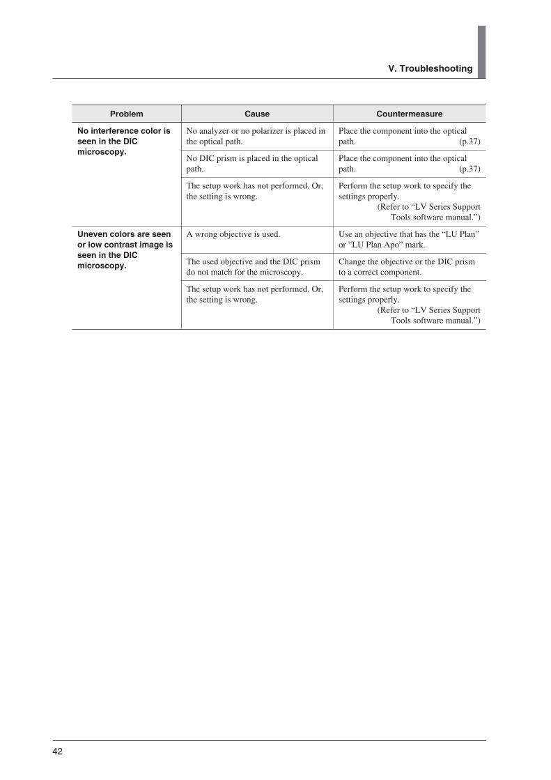
Problem
No interference color isseen in the DICmicroscopy.
Uneven colors are seenor low contrast image isseen in the DICmicroscopy.
Countermeasure
Place the component into the opticalpath. (p.37)
Place the component into the opticalpath. (p.37)
Perform the setup work to specify thesettings properly.
(Refer to “LV Series SupportTools software manual.”)
Use an objective that has the “LU Plan”or “LU Plan Apo” mark.
Change the objective or the DIC prismto a correct component.
Perform the setup work to specify thesettings properly.
(Refer to “LV Series SupportTools software manual.”)
Cause
No analyzer or no polarizer is placed inthe optical path.
No DIC prism is placed in the opticalpath.
The setup work has not performed. Or,the setting is wrong.
A wrong objective is used.
The used objective and the DIC prismdo not match for the microscopy.
The setup work has not performed. Or,the setting is wrong.

43
Care and Maintenance
Nikon recommends daily care and maintenance for maintaining the performance as long aspossible.Do not let dust, fingerprint, etc. get on the lenses. Dirt on the lenses, filters, and the like willadversely affect the optical performance of the microscope.If lenses are contaminated, clean them according to the procedure described in “1. Cleaning thelenses and Filters.” When cleaning, be sure to turn off the power switch (flip the switch to “ ” side)to avoid malfunction.
Daily care and maintenance
Clean the parts frequently manipulated by hands, such as eyepieces and glass plate according to theprocedure described in “1. Cleaning Lenses and Filters” without removing them from themicroscope. Nikon recommends cleaning them frequently.Clean the objectives, filters, and the like to maintain the optical performance. When cleaning theobjectives, remove them from the microscope. Clean them whenever they are contaminated.Microscopes and stages are contaminated with use. When you find the microscope is contaminated,clean them according to the description in “2. Cleaning the Painted, Plastic, and Printed Parts.”
Cleaning tool and supplies (consumables)
• Cleaning toolBrush (with soft bristles) (Use a cleanroom wiper in a cleanroom.)
• Cleaning supplies (consumables)Ethyl or methyl alcoholLens tissue (Use a cleanroom wiper in a cleanroom.)

44
1 Cleaning Lenses and Filters
Do not let dust, fingerprint, etc. get on the lenses and filters. Dirt on the lenses, filters, etc. willadversely affect the view of image. If any lens gets dirty, clean it as described below.• Either brush away dust with a soft brush, or else gently wipe it off with a piece of gauze.• Only if there are fingerprints or grease on a lens, dampen lightly a piece of soft, clean cotton
cloth, lens tissue, or gauze with absolute alcohol (ethyl or methyl) and gently wipe off the dirt.• Absolute alcohol is highly flammable. Be careful when handling it, when around open flames,
when turning the power switch on/off, etc.• Follow the instructions provided by the manufacturer when using absolute alcohol.
2 Cleaning the Painted Parts, Plastic Parts, and Printed Parts
Do not use organic solvents such as alcohol, ether, or paint thinner on painted components, plasticcomponents, or printed components. Doing so could result in discoloration or in peeling of theprinted characters. For persistent dirt, dampen a piece of gauze with neutral detergent and wipegently.
3 Storage
• Store this product in a dry place where mold is not likely to form.• Store the objectives and eyepieces in a desiccator or similar container with a drying agent.• Put the dust-proof cover over this product to protect it from dust.• Before putting on the dust-proof cover, turn off the power switch of the microscope system (flip it
to the “ ” position) and wait until the lamp house gets cool sufficiently.
4 Regular Inspections
Periodical inspections of this product are recommended in order to maintain peak performance.Contact your nearest Nikon representative for details.
VI. Care and Maintenance

45
Specifications
LV-ECON E controller
Model name
Controllable devices
Interface connectors
Input ratings
Power cord
Operating conditions
Storage conditions
External dimensions
Weight
LV-ECON E controller
Motorized nosepiece: LV-NU5A motorized universal quintuple nosepiece ESD,LV-NU5AC motorized universal quintuple centerable nosepiece
Motorized DIC nosepiece: LV-MDIC motorized DIC moduleMotorized epi illuminator: LV-UEPI2A motorized universal epi illuminator 2AMotorized focusing module:
LV-FMA FM module A (motorized drive),LV-IMA IM module A (motorized drive)
Auto focus system: LV-AF auto focusPower supply for the lamp: TE2-PS100W power supplyLED epi illuminator: LV-EPILED epi illuminator LEDExternal light source: C-HGFIE Intensilight (precentered fiber illuminator)
X-Cite 120 PC manufactured by EXFOPC: Windows PC with an USB interface
External light source interface connector: RS232C interfaceAF controller interface connector: RS232C interfacePower supply interface connector for the diascopic illumination: Special interfaceInterface connector for the power supply for the episcopic illumination or for the LED epiilluminator: Special interfaceInterface connector for a PC: USB 1.1 interfaceInterface connector for the motorized epi illuminator: Special interfaceInterface connector for the motorized focusing module: Special interfaceInterface connector for the motorized DIC: Special interfaceInterface connector for the motorized nosepiece: Special interface
100-240 VAC, 1.0A, 50/60Hz
When the supply voltage is 100 V to 120 V:UL Listed detachable cord set, 3 conductor grounding Type(3 conductor grounding Type SVT, NO.18 AWG, 3m longmaximum, rated at 125 VAC minimum)
When the supply voltage is 220 V to 240 V:Cord set approved according to EU/EN standards, 3 conductorgrounding Type (3 conductor grounding Type H05VV-F,3m long maximum, rated at 250 VAC minimum)
When used in Japan: Cord set satisfying the Electrical Appliance And Material SafetyLaw (PSE mark attached)(3 conductor grounding VCTF 3x0.75mm2, 3m long maximum,rated at 125 VAC minimum)
Temperature: 0°C to +40°CHumidity: 85% relative humidity maximum (no condensation)Altitude: 2000m maximumPollution degree: Degree 2Installation category: Category IIElectric shock protection class: Class IIndoor use only
Temperature: -20°C to +60°CHumidity: 90% relative humidity maximum (no condensation)
165 mm (width) x 109 mm (height) x 210 mm (depth) (excluding protrusions)
Approx. 2.2 kg

46
Safety standardscompliance
• This is UL-listed product (UL61010A-1).
• This product meets FCC Part 15B Class A requirements:
This equipment has been tested and found to comply with the limits for a Class Adigital device, pursuant to Part 15 of the FCC Rules.
These limits are designed to provide reasonable protection against harmful interferencewhen the equipment is operated in a commercial environment.
This equipment generates, uses, and can radiate radio frequency energy and, if notinstalled and used in accordance with the instruction manual, may cause harmfulinterference to radio communications.
Operation of this equipment in a residential area is likely to cause harmful interferencein which case the user will be required to correct the interference at his own expense.
• This Class A digital apparatus complies with Canadian ICES-003.Cet appreil numérique de la classe A est conforme à la norme NMB-003 du Canada.
• This product complies with Australian EMI (AS/NZS CISPR11 Group 1 Class A)
CE marking• This product meets EU Low Voltage Directive requirements.• This product meets EU EMC Directive requirements.

47
VII. Specifications
Model name
Focusing mechanism
Mounting part for theoptical parts
Mounting hole
Designated controller
Interface
Operating conditions
Storage conditions
External dimensions
Weight
Safety standardscompliance(Tested with theLV-ECON)
LV-FMA FM module A (motorized drive)
Motorized drive type (controlled from optional LV-ECON)Stroke: 20 mm (19 mm up and 1 mm down from the reference position)
Resolution of movement: 0.05 µmSpeed: 2.5 mm/sec maximumUseful load: 3 to 6 kg (standard condition)
6 to 9 kg (with optional counter spring)
Eyepiece tube mounting part:Round dovetail joint(reference dimension for the dovetail diameter: 46 mm)
Nosepiece mounting part:Dovetail joint(reference width: 50 mm, sliding dovetail joint with trapezoid shape)
Bottom: Four M6 screw holes(distance between holes: 80 x 62 mm, four fixing bolts are attachedwith the product)
LV-ECON E controller
LV-ECON special interface
Temperature: 0°C to -40°CHumidity: 85% relative humidity maximum (no condensation)Altitude: 2000 m maximumPollution degree: Degree 2Installation category: Category IIElectric shock protection class: Class IIIIndoor use only
Temperature: -20°C to +60°CHumidity: 90% relative humidity maximum (no condensation)
W : 123.8 mm x H : 225 (224 to 244) mm x D : 308 mm
Approx. 6.0 kg
• This is UL-listed product (UL61010A-1).
• This product meets FCC Part 15B Class A requirements:
This equipment has been tested and found to comply with the limits for a Class Adigital device, pursuant to Part 15 of the FCC Rules.
These limits are designed to provide reasonable protection against harmful interferencewhen the equipment is operated in a commercial environment.
This equipment generates, uses, and can radiate radio frequency energy and, if notinstalled and used in accordance with the instruction manual, may cause harmfulinterference to radio communications.
Operation of this equipment in a residential area is likely to cause harmful interferencein which case the user will be required to correct the interference at his own expense.
• This Class A digital apparatus complies with Canadian ICES-003.Cet appreil numérique de la classe A est conforme à la norme NMB-003 du Canada.
• This product complies with Australian EMI (AS/NZS CISPR11 Group 1 Class A)
CE marking• This product meets EU Low Voltage Directive requirements.• This product meets EU EMC Directive requirements.
LV-FMA

48
Model name
Focusing mechanism
Mounting part for theoptical parts
Mounting hole
Designated controller
Interface
Operating conditions
Storage conditions
External dimensions
Weight
Safety standardscompliance(Tested with theLV-ECON)
LV-IMA IM module A (motorized drive)
Motorized drive type (controlled from optional LV-ECON)Stroke: 20 mm (19 mm up and 1 mm down from the reference position)Resolution of movement: 0.05 µmSpeed: 2.5 mm/sec maximumUseful load: 4 to 7 kg (standard condition)
7 to 10 kg (with optional counter spring)
Eyepiece tube mounting part: Round dovetail joint(reference dimension for the dovetail diameter: 46 mm)
Nosepiece mounting part: Dovetail joint(reference width: 50 mm, sliding dovetail joint with trapezoid shape)
Rear: Four M6 screw holes(distance between holes: 95 x 120 mm, depth: 10 mm)
Bottom: Four M6 screw holes(distance between holes: 80 x 62 mm,maximum length of screw: 11mm)
LV-ECON E controller
LV-ECON special interface
Temperature: 0°C to + 40°CHumidity: 85% relative humidity maximum (no condensation)Altitude: 2000 m maximumPollution degree: Degree 2Installation category: Category IIElectric shock protection class: Class IIIIndoor use only
Temperature: -20°C to +60°CHumidity: 90% relative humidity maximum (no condensation)
114 (W) x 138.8 (H) x 217 (D) mm (excluding protrusions)
Approx. 3.7 kg
• This is UL-listed product (UL61010A-1).
• This product meets FCC Part 15B Class A requirements:
This equipment has been tested and found to comply with the limits for a Class Adigital device, pursuant to Part 15 of the FCC Rules.
These limits are designed to provide reasonable protection against harmful interferencewhen the equipment is operated in a commercial environment.
This equipment generates, uses, and can radiate radio frequency energy and, if notinstalled and used in accordance with the instruction manual, may cause harmfulinterference to radio communications.
Operation of this equipment in a residential area is likely to cause harmful interferencein which case the user will be required to correct the interference at his own expense.
• This Class A digital apparatus complies with Canadian ICES-003.Cet appreil numérique de la classe A est conforme à la norme NMB-003 du Canada.
• This product complies with Australian EMI (AS/NZS CISPR11 Group 1 Class A)
CE marking• This product meets EU Low Voltage Directive requirements.• This product meets EU EMC Directive requirements.
LV-IMA

49
VII. Specifications
Model name
Optical system
Light sourceconnection
Illumination
Field number
Illumination method
Illumination selectionmethod
Field diaphragm
Aperture diaphragm
Filters
Interface
Operating condition
Storage condition
LV-UEPI2A Motorized Universal Epi Illuminator 2A
CFI60 system (chromatic aberration free infinity optics system)
1 (rear)
Köhler illumination
25
Bright-field, dark-field, DIC*, simplified polarization*, sensitive color polarization*, epi-fl*(* needs options)
Four port turret rotation in conjunction with a shutter to provide dazzling light(noise terminator attached)Turret drive method: motorFilter cube: up to two filter cubes can be installed (filter cubes for the
bright-field and dark-field microscopy are fixed)
Adjustment: manualVariable range: 1.0 to 8.9 mm in diameter (bright-field microscopy)Projected magnification: 3.0x (on the eyepiece image plane)Full open diameter (for dark-field microscopy):
9.8 mmCentering range: 2.4 mm in diameter
Adjustment: motorizedVariable range: 1.2 to 8.0 mm in diameter (bright-field microscopy)Projected magnification: 1.55x (on the objective pupil plane)Full open diameter (for dark-field microscopy):
8.5 mmCentering range: 2.4 mm in diameter
Built-in filter: lemon skin filter,UV filter (only for bright-field and dark-field microscopy)
ND filter: two manual type slidersAnalyzer slot: right sidePolarizer slot: two slots on right side, lambda plate attachableExcitation light balancer slot: left side
Special interface (for LV100DA or LV-ECON)
Temperature: 0°C to +40°CHumidity: 85% relative humidity maximum (no condensation)Altitude: 2000 m maximumPollution degree: Degree 2Installation category: Category IIElectric shock protection class: Class IIIIndoor use only
Temperature: -20°C to +60°CHumidity: 90% relative humidity maximum (no condensation)
LV-UEPI2A

50
LV-EPILED
Model name
Illumination type
Source connection
Optical system
Illumination method
Field number
Light source unit
Filter
LED controller unit
Power source
AC adapter
Power cord forAC adapter
External connection
Operating conditions
Storage conditions
LV-EPILED epi illuminator LED
Köhler illumination
1 (rear)
CFI60 system (chromatic aberration free infinity optics system)
Bright field
25
Light source: White LEDElectric power consumption: 3WColor temperature: 5,500K
Integrated lemon skin filterø 25 filter sliders (ND4 and ND16, for the slots on the right side)
LED lamp input voltage and maximum current:12 VDC ±5%, 1 A maximum (supplied from the AC adapter)
AC adapter
Manufacturer: Electricity Power Source (E.P.S.) Inc.Model name: F1650KRated input: 100 to 240 VAC ±10%, 1.2 A maximum, 50-60 HzRated output: 12VDC, 3.5 A maximumCertifications: UL listed, GS approved, and CE marking approved.
When the supply voltage is 100 V to 120 V:UL Listed detachable cord set, 3 conductor grounding type(3 conductor grounding Type SVT, NO.18 AWG, 3 m longmaximum, rated at 125 VAC minimum)
When the supply voltage is 220 V to 240 V:Cord set approved according to EU/EN standards, 3 conductorgrounding type (3 conductor grounding Type H05VV-F,3 m long maximum, rated at 250 VAC minimum)
When used in Japan: Cord set satisfying the Electrical Appliance And MaterialSafety Law (PSE mark attached)(3 conductor grounding VCTF 3x0.75mm2, 3 m long maximum,rated at 125 VAC minimum)
LED connectorExternal control connector (special interface, for LV-ECON)12 VDC input connector (for connecting to the AC adapter)
Temperature: 0 °C to + 40 °CHumidity: 85% relative humidity maximum (no condensation)Altitude: 2000 m maximumPollution degree: Degree 2Installation category: Category IIElectric shock protection class: Class I (AC adapter)Indoor use only.
Temperature: -20 °C to + 60 °CHumidity: 90% relative humidity maximum (no condensation)

51
Safety standardscompliance
• This is UL-listed product (UL61010A-1).
• This product meets FCC Part 15B Class A requirements:
This equipment has been tested and found to comply with the limits for a Class Adigital device, pursuant to Part 15 of the FCC Rules.
These limits are designed to provide reasonable protection against harmful interferencewhen the equipment is operated in a commercial environment.
This equipment generates, uses, and can radiate radio frequency energy and, if notinstalled and used in accordance with the instruction manual, may cause harmfulinterference to radio communications.
Operation of this equipment in a residential area is likely to cause harmful interferencein which case the user will be required to correct the interference at his own expense.
• This Class A digital apparatus complies with Canadian ICES-003.Cet appreil numérique de classe A est conforme à la norme NMB-003 du Canada.
• This product complies with Australian EMI (AS/NZS CISPR11 Group 1 Class A)
CE marking
• This product meets EU Low Voltage Directive requirements.
• This product meets EU EMC Directive requirements.
Laser safety• This product complies with IEC/EN 60825-1, Class 1 standards. (Class 1 LED Product)
VII. Specifications

52
Model name
Mountable objectivenumber
Objective switchingmethod
Dimensions
Joint part to themicroscope
Slot size for theNomarski prism slider
Objective centeringmechanism(only for LV-NU5AC)
Interface
Operating condition
Storage condition
LV-NU5A motorized universal quintuple nosepieceLV-NU5AC motorized universal quintuple centerable nosepiece
5
Rotating the motorized nosepieceNosepiece drive device: center motorSwitching time: approximately 0.5 seconds
Overall height: 88.8 mmRevolver outer diameter: 127 mmKnurling angle: 15°Dimension of objective thread: M32 x 0.75 mmDistance between the attachment position of the objective barrel and the attachmentreference position of the nosepiece: 48 mm
Sliding dove tail (reference dimension: 50 mm)
16.5 mm x 24 mm
One fixed objective and four centerable objectivesCentering screws: two M3 set screws (two screws for each objective)Centering range: ø0.3mm
Connector of 12-pin
Temperature: 0°C to +40°CHumidity: 85% relative humidity maximum (no condensation)Altitude: 2000 m maximumPollution degree: Degree 2Installation category: Category IIElectric shock protection class: Class IIIIndoor use only
Temperature: -20°C to +60°CHumidity: 90% relative humidity maximum (no condensation)
LV-NU5A, LV-NU5AC

53
Model name
Mountable objectivenumber
Objective switchingmethod
Dimensions of thenosepiece
Mounting part
Nomarski prism part
Interface
External dimensions
Operating condition
Storage condition
LV-MDIC motorized DIC module
5
Rotating the motorized nosepieceNosepiece drive device: center motorSwitching time: approximately 0.5 seconds
Revolver outer diameter: 127 mmRevolver tilt angle: 15 °Dimension of objective thread: M32 x 0.75 mm
Arm mounting part: 6-mm-diameter hole x 6 locationsFour fixing holes including the reference hole (X: 80 and Y:90, or X: 80 and Y: 118) and shoulder bolts are used for fixing.
Eyepiece tube mounting part: Circular dovetail joint (reference dimension for the circulardovetail diameter: 46 mm)
Epi illuminator mounting part: Circular dovetail joint and M4 tapDistance between the arm mounting surface and the eyepiece tube mounting surface: 28 mmDistance between the objective body mounting position and the eyepiece tube mounting surface:
73 mm
Insertion/removal travel distance: 32 mmInsertion/removal time: Approximately 4 seconds or lessContrast adjustable range: 7.8 mmContrast conversion range: -1/2 λ to +3/2 λVertical travel distance (position A/B selection):
5.4 mm (interlocked with the objective selection)Position A/B changeover time: Approximately 1.5 seconds or less
12-pin circular connector: For nosepiece control (LV-ECON)16-pin rectangular connector: For DIC prism control (LV-ECON)
External dimensions: 185 mm (width) x 114 mm (height) x 385 mm (depth)
Temperature: 0°C to +40°CHumidity: 85% relative humidity maximum (no condensation)Altitude: 2000 m maximumPollution degree: Degree 2Installation category: Category IIElectric shock protection class: Class IIIIndoor use only
Temperature: -20°C to +60°CHumidity: 90% relative humidity maximum (no condensation)
VII. Specifications
LV-MDIC

54
Safety standardscompliance(Tested with theLV-ECON)
• This is UL-listed product (UL61010-1 2nd Edition).
• This product meets FCC Part 15B Class A requirements:
This equipment has been tested and found to comply with the limits for a Class Adigital device, pursuant to Part 15 of the FCC Rules.
These limits are designed to provide reasonable protection against harmful interferencewhen the equipment is operated in a commercial environment.
This equipment generates, uses, and can radiate radio frequency energy and, if notinstalled and used in accordance with the instruction manual, may cause harmfulinterference to radio communications.
Operation of this equipment in a residential area is likely to cause harmful interferencein which case the user will be required to correct the interference at his own expense.
• This Class A digital apparatus complies with Canadian ICES-003.Cet appreil numérique de la classe A est conforme à la norme NMB-003 du Canada.
• This product complies with Australian EMI (AS/NZS CISPR11 Group 1 Class A)
CE marking• This product meets EU Low Voltage Directive requirements.• This product meets EU EMC Directive requirements.

55
TE2-PS100W
Model name
Input ratings
Power cord
Output ratings
Built-in fuse ratings
Operating conditions
Storage conditions
Safety standardscompliance
TE2-PS100W power supply
100 to 240VAC, 2.4A, 50/60 Hz
When the supply voltage is 100 V to 120 V:UL Listed detachable cord set, 3 conductor grounding Type(3 conductor grounding Type SVT, NO.18 AWG, 3m longmaximum, rated at 125 VAC minimum)
When the supply voltage is 220 V to 240 V:Approved according to EU/EN standards, 3 conductor groundingType (3 conductor grounding Type H05VV-F, 3m longmaximum, rated at 250 VAC minimum)
When used in Japan: Cord set satisfying the Electrical Appliance And Material SafetyLaw (PSE mark attached)(3 conductor grounding VCTF 3x0.75mm2, 3m long maximum,rated at 125 VAC minimum)
12VDC, 100W, 8.4A
250V T4A
Temperature: 0°C to +40°CHumidity: 85% relative humidity maximum (no condensation)Altitude: 2000 m maximumPollution degree: Degree 2Installation category: Category IIElectric shock protection class: Class IIndoor use only
Temperature: -20°C to +60°CHumidity: 90% relative humidity maximum (no condensation)
UL listed, GS approved, CE certified
VII. Specifications

56
C-HGFIE
Model name
Shutter
Light control function
Available mercury lamp
Availablelight guide fiber
Input ratings
Power cord
Dimensions and weight
Remote controller(only for C-HGFIE)
C-HGFIE Intensilight (precentered fiber illuminator)
Shutter system: light shield plate insertion/removal typeDrive system: motorized type
Light control system: punching metal rotationLight control range: ND1, ND2, ND3, ND4, ND8, ND16, and ND32 (6 steps)Wavelength range: 380 to 600 nmDrive system: motorized type
Model name: Nikon C-LHGFI HG lampRatings: 130 W DCLighting system: DC lightingAverage service life *: 2,000 hrs.
* The average service life is defined as the hours at which 50%or more normally working lamps still light up with thebrightness of 50% or more of the initial optical characteristicsafter the usage of lifetime lighting (lighting cycle: repetition of3.5 hours on, and then 0.5 hour off).
Model name: Nikon HG fiber 15 C-HGFIF15 (cable length 1.5 m)Nikon HG fiber 30 C-HGFIF30 (cable length 3.0 m)
Core diameter: 3 mm
100 to 240 VAC (±10%), 50/60 Hz, 2.0 A
When the supply voltage is 100 V to 120 V:UL Listed detachable cord set, 3 conductor grounding Type(3 conductor grounding Type SVT, No.18 AWG, 3 m longmaximum, rated at 125 VAC minimum)
When the supply voltage is 220 V to 240 V:Cord set approved according to EU/EN standards, 3 conductorgrounding Type (3 conductor grounding Type H05VV-F,3 m long maximum, rated at 250 VAC minimum)
When used in Japan: Cord set satisfying the Electrical Appliance And Material SafetyLaw (PSE mark attached)(3 conductor grounding VCTF 3x0.75mm2, 3 m long maximum,rated at 125 VAC minimum)
Dimensions: 110 (W) x 283 (H) x 258 (D) mm(C-HGFIE main body excluding protruding portion)
Weight: approximately 6.0 kg
Model name: C-HGFIE-C HG controllerConnector: mini DIN 8 pinCable length: 2.8 mDimensions: 67 (W) x 122 (H) x 20 (D) mm (excluding protruding portion)

57
VII. Specifications
Communicationfunction
Shutter control signal
Operating environment
Storage environment
Safety standardcompliance
Acoustic Noise
Communication type: RS-232C compliance serial interfaceConnector: D-sub 9 pin
Connector: 3.5 mm diameter type stereo mini jack
Temperature: 0 to +35°CRelative humidity: 85% relative humidity maximum (no condensation)Altitude: 2000 m maximumPollution degree: Degree 2Installation category: Category IIElectric shock protection class: Class IIndoor use only
Temperature: -20 to +60°CRelative humidity: 90% relative humidity maximum (no condensation)
CE marking• This product meets EU Low Voltage Directive requirements.• This product has obtained GS mark. (EN61010-1:2001)• This product meets EU EMC Directive requirements. (EN61326)
• This is the UL-listed product.(UL61010-1 (Second Edition))
• This product meets FCC Part 15B Class A requirements.
This equipment has been tested and found to comply with the limits for a Class Adigital device, pursuant to Part 15 of the FCC Rules.
These limits are designed to provide reasonable protection against harmful interferencewhen the equipment is operated in a commercial environment.
This equipment generates, uses, and can radiate radio frequency energy and, if notinstalled and used in accordance with the instruction manual, may cause harmfulinterference to radio communications.
Operation of this equipment in a residential area is likely to cause harmful interferencein which case the user will be required to correct the interference at his own expense.
• This Class A digital apparatus complies with Canadian ICES-003.Cet appreil numérique de la classe A est conforme à la norme NMB-003 du Canada.
• This product complies with Australian EMI. (AS/NZS C1SPR11 Group1 Class B)
Less than 70 dB
Maschinenlärminformations-Verordnung - 3. GPSGV, 06.01.2004:Der höchste Schalldruckpegel beträgt 70 dB(A) oder weniger gemäß EN ISO 7779