Embed Size (px)
Citation preview
24 Napoleon Road, Barrie, Ontario, Canada L4M 0G8 • 214 Bayview Drive, Barrie, Ontario, Canada L4N 4Y8Fireplaces, Heating and Cooling: 705-721-1212 • Grills: 705 726-4278 • napoleonproducts.com
LUXURIA™ 74 DIRECT VENT LINEAR GAS APPLIANCE
W415-1880 / 11.10.18
Specifications
Glass Guard Assembly
Framing Dimensions
Model BTUWidth Height Depth
Viewing AreaActual Framing Actual Framing Actual Framing
LVX74N 50,000 89 5/16 89 13/16 41 3/16 91 17 11/16 18 78 1/8 X 18 5/8LVX74N2 50,000 89 5/16 89 13/16 41 3/16 91 16 3/16 16 3/16 78 1/8 X 18 5/8
single-sided
Ref LVX74
E 18” (45.7cm)
F 89 13/16” (228.1cm)
J Optional - Appliance does not need to be elevated above floor
*L 91” (231.1cm)
EJ
F
minimum framing
L
note:The LVX series requires a minimum enclosure height of 91” measured from the bottom of the appliance. For temperature requirements, this area must be left unobstructed. Some venting configurations that require more vertical rise will require a larger enclosure to provide minimum vertical clearance between vent pipes and combustibles.
note:Before framing the appliance, ensure to install the firestop first.
see-thru
Before framing the appliance, ensure to install the firestop first as it will not fit between the studs if installed after framing.
* Minimum enclosure height maybe higher depending on venting configuration (see minimum distance to combustibles).
Ref LVX74
E 16 3/16” (41.1cm)
F 89 13/16” (228.1cm)
J Optional - Appliance does not need to be elevated above floor
*L 91” (231.1cm)
E F
J
minimum framing
L
note:The LVX series requires a minimum enclosure height of 91” measured from the bottom of the appliance. For temperature requirements, this area must be left unobstructed. Some venting configurations that require more vertical rise will require a larger enclosure to provide minimum vertical clearance between vent pipes and combustibles.
note:
Product information provided is not complete and is subject to change without notice. Please consult the installation manual for the most up to date installation information.
0.047
0.047
75.594
0.750
24 Napoleon Road, Barrie, Ontario, Canada L4M 0G8 • 214 Bayview Drive, Barrie, Ontario, Canada L4N 4Y8Fireplaces, Heating and Cooling: 705-721-1212 • Grills: 705 726-4278 • napoleonproducts.com
LUXURIA™ 74 DIRECT VENT LINEAR GAS APPLIANCE
Product information provided is not complete and is subject to change without notice. Please consult the installation manual for the most up to date installation information.
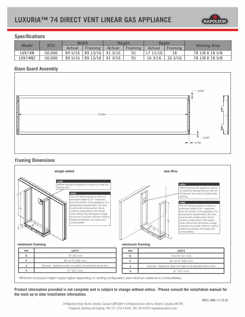
Dimensions
Wall Penetration
Appliance LocationCombustible Mantel Clearances
LVX74A
(Finishing Flange)78 1/8”
(1984mm)B 89 5/16”
(2269mm)C 93 5/16”
(2370mm)
single-sided
LVX74A
(Finishing Flange)78 1/8”
(1984mm)B 89 5/16”
(2269mm)C 93 5/16”
(2370mm)
see-thru
The LVX series requires a minimum enclosure height of 91” (231.1cm) measured from the bottom of the appliance. For temperature requirements, this area must be left unobstructed. Some venting configurations that require more vertical rise will require a larger enclosure to provide minimum vertical clearance between vent pipes and combustibles.
note:
Horizontal vent sections: A minimum clearance of 3” (76mm) on the top outside of the enclosure and 2” (51mm) on the sides and bottom outside of the enclosure all around the vent pipe on all horizontal runs to combustibles is required. Horizontal vent sections within enclosures require a minimum clearance of 6”(152mm) at the top of the vent pipe. Vertical vent sections: A minimum of 1” (25mm) all around the vent pipe on all vertical runs to combustibles is required except for clearances in appliances enclo-sures. Vertical vent sections within enclosures require a minimum clearance of 1” (25mm) around the vent pipe.
see-thru
Horizontal vent sections: A minimum clearance of 3” (76mm) on the top outside of the enclosure and 2” (51mm) on the sides and bottom outside of the enclosure all around the vent pipe on all horizontal runs to combustibles is required. Horizontal vent sections within enclosures require a minimum clearance of 6”(152mm) at the top of the vent pipe. Vertical vent sections: A minimum of 1” (25mm) all around the vent pipe on all vertical runs to combustibles is required except for clearances in appliances enclosures. Vertical vent sections within enclosures require a minimum clearance of 1” (25mm) around the vent pipe.
0
HEIGHT
MANTEL
MANTEL DEPTH1 2 3 4 5 6 7 8 9 1011
2468
1012141618202224
ED C B
A A
Top of finishing flange
Bottom of the appliance
25 11/16" (65.2cm)
2”
Bottom of finishing flange
Optional hearth extension (no
depth restriction)
MANTEL HEIGHT
MANTEL DEPTH
LVX74*E 18” (45.7cm)F 89 13/16” (228.1cm)G 89 1/4” (226.6cm)H 18 3/16” (46.2cm)I 126 1/8” (320.4cm)
minimum framing
W415-1880 / 11.10.18
*Single-sided model illustrated.
The LVX series requires a minimum enclosure height of 91” (231.1cm) mea-sured from the bottom of the appliance. For temperature requirements, this area must be left unobstructed. Some venting configurations that require more vertical rise will require a larger enclosure to pro-vide minimum vertical clearance between vent pipes and combustibles.
note:
Shaded components (finish framing) must be non-combustible materials.
note:
41 3/16"1046mm
7 1/16"179mm
18 5/8"473mm
3 1/8"80mm
17 3/16"
437mm
32 3/4"832mm
39 11/16"1008mm
8 1/16"205mm
8 1/16"205mm
Ø 8"203mm
Ø 5"127mm
GLASS GUARD
1/2"[12.7mm]
A
B
*
Base of air collar
17 11/16” (449mm)
6” [152mm] minimum (inside enclosure)
0” to back standoffs
0” to bottom of the appliance
0” to side standoffs
When passing through a ceiling, use firestop spacer W500-0028 (not supplied)
1” [25mm] minimum all sides for sections of vertical venting.
1/2” finishing flange
3” [76mm] to top (outside of enclosure)
2” [51mm] to sides / bottom (outside of enclosure)
When passing through a wall, use firestop spacer assembly W010-4178 (supplied)
0” to non-combustible finishing such as brick and stone. When using non-combustible finishing, only use firestop spacer (W615-0162) included in the firestop assembly (W010-4178)
6” [152mm] minimum(inside enclosure)
0” to side standoffs
0” to base of the appliance
When passing through a ceiling, use firestop spacer W500-0028 (not supplied)
1” [25mm] minimum all sides for sections of vertical venting.
1/2” finishing flange (4 sides)
GLASS GUARD
3” [76mm] to top (outside of enclosure)
2” [51mm] to sides / bottom (outside of enclosure)When passing through a wall, use firestop spacer assembly W010-4178 (supplied)0” to non-combustible finishing such as brick and stone. When using non-combustible finish-ing, only use firestop spacer (W615-0162) included in the firestop assembly (W010-4178)
91”
14” (35.6cm) min.
3” [76mm] (minimum all sides for sections of horizontal venting) outside of enclosure.
Do not put objects in front of the appliance (minimum
distance of 4 feet)
F
G
F
H
I
E
1” (2.54cm) min.
6” (15.2cm) min.
41 3/16"1046mm
7 1/16"179mm
18 5/8"473mm
3 1/8"80mm
32 3/4"832mm
39 11/16"1008mm
16 3/16"411mm
8 1/16"205mm
8 1/16"205mm
Ø 8"203mm
Ø 5"127mm
GLASS GUARD
1/2"[12.7mm] 1/2"
[12.7mm]
A
B
C
**
Base of air collar
minimum91”
minimum
single-sided
*Finishing flange depth. (The finishing flange defines the perimeter of the fireplace opening. Framing or finishing materials must NEVER encroach inside the finishing flange.)
*Finishing flange depth. (The finishing flange defines the perimeter of the fireplace opening. Framing or finishing materials must NEVER encroach inside the finishing flange.)
24 Napoleon Road, Barrie, Ontario, Canada L4M 0G8 • 214 Bayview Drive, Barrie, Ontario, Canada L4N 4Y8Fireplaces, Heating and Cooling: 705-721-1212 • Grills: 705 726-4278 • napoleonproducts.com
SÉRIE LUXURIAMD 74 FOYER À GAZ D’ÉVACUATION DIRECTE
W415-1880 / 11.10.18
Spécifications
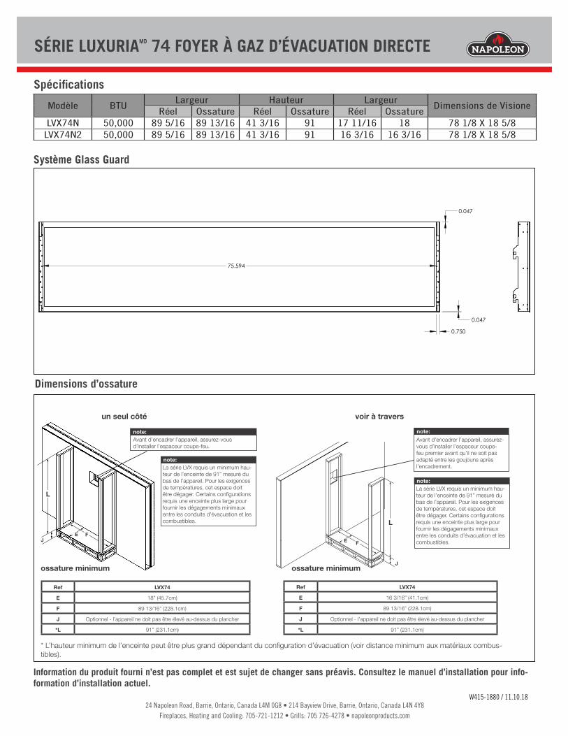
Système Glass Guard
Dimensions d’ossature
Modèle BTULargeur Hauteur Largeur
Dimensions de VisioneRéel Ossature Réel Ossature Réel Ossature
LVX74N 50,000 89 5/16 89 13/16 41 3/16 91 17 11/16 18 78 1/8 X 18 5/8LVX74N2 50,000 89 5/16 89 13/16 41 3/16 91 16 3/16 16 3/16 78 1/8 X 18 5/8
Ref LVX74
E 18” (45.7cm)
F 89 13/16” (228.1cm)
J Optionnel - l’appareil ne doit pas être élevé au-dessus du plancher
*L 91” (231.1cm)
EJ
F
ossature minimum
L
note:La série LVX requis un minimum hau-teur de l’enceinte de 91” mesuré du bas de l’appareil. Pour les exigences de températures, cet espace doit être dégager. Certains configurations requis une enceinte plus large pour fournir les dégagements minimaux entre les conduits d’évacuation et les combustibles.
note:Avant d’encadrer l’appareil, assurez-vous d’installer l’espaceur coupe-feu.
Avant d’encadrer l’appareil, assurez-vous d’installer l’espaceur coupe-feu premier avant qu’il ne soit pas adapté entre les goujouns après l’encadrement.
Ref LVX74
E 16 3/16” (41.1cm)
F 89 13/16” (228.1cm)
J Optionnel - l’appareil ne doit pas être élevé au-dessus du plancher
*L 91” (231.1cm)
E F
Jossature minimum
L
note:La série LVX requis un minimum hau-teur de l’enceinte de 91” mesuré du bas de l’appareil. Pour les exigences de températures, cet espace doit être dégager. Certains configurations requis une enceinte plus large pour fournir les dégagements minimaux entre les conduits d’évacuation et les combustibles.
note:
Information du produit fourni n’est pas complet et est sujet de changer sans préavis. Consultez le manuel d’installation pour info-formation d’installation actuel.
0.047
0.047
75.594
0.750
* L’hauteur minimum de l’enceinte peut être plus grand dépendant du configuration d’évacuation (voir distance minimum aux matériaux combus-tibles).
un seul côté voir à travers

24 Napoleon Road, Barrie, Ontario, Canada L4M 0G8 • 214 Bayview Drive, Barrie, Ontario, Canada L4N 4Y8Fireplaces, Heating and Cooling: 705-721-1212 • Grills: 705 726-4278 • napoleonproducts.com
SÉRIE LUXURIAMD 74 FOYER À GAZ D’ÉVACUATION DIRECTE
Information du produit fourni n’est pas complet et est sujet de changer sans préavis. Consultez le manuel d’installation pour info-formation d’installation actuel.
Dimensions
Passage d’un section dans un mur
Location de l’appareilDégagements Combustible de la Tablette
LVX74A
(Bride de finition)78 1/8”
(1984mm)B 89 5/16”
(2269mm)C 93 5/16”
(2370mm)
* La profondeur de la bride de finition (la bride de finition définit le périmètre de l’ouverture de la cheminée. Les matériaux de charpente ou de finition NE JAMAIS empiété à l’intérieur de la bride de finition.
LVX74A
(Bride de finition)78 1/8”
(1984mm)B 89 5/16”
(2269mm)C 93 5/16”
(2370mm)
La série LVX nécessite une hauteur minimale de 91” (231,1cm) mesurée par le bas de l’appareil. Pour les exigences de températures, l’espace doit être laisser sans obstruction. Certains configurations qui requis une course verticale plus large aura besoin d’une enceinte plus large pour fournir les dégagements minimaux entre les conduits d’évacuation et les combustibles.
note:
0
HEIGHT
MANTEL
MANTEL DEPTH1 2 3 4 5 6 7 8 9 1011
2468
1012141618202224
ED C B
A A
Top of finishing flange
Bottom of the appliance
25 11/16" (65.2cm)
2”
Bottom of finishing flange
MANTEL HEIGHT
MANTEL DEPTH
LVX74*E 18” (45.7cm)F 89 13/16” (228.1cm)G 89 1/4” (226.6cm)H 18 3/16” (46.2cm)I 126 1/8” (320.4cm)
ossature minimum
W415-1880 / 11.10.18
*Modèle d’un seul côté illustré.
La série LVX nécessite une hauteur minimale de 91” (231,1cm) mesurée par le bas de l’appareil. Pour les exigences de températures, l’espace doit être laisser sans obstruction. Certains configurations qui requis une course verticale plus large aura besoin d’une enceinte plus large pour fournir les dégagements minimaux entre les conduits d’évacuation et les combustibles.
note:
Les composants ombragés (encadre-ment de finition) doivent être de matériaux incombustibles.
note:
41 3/16"1046mm
7 1/16"179mm
18 5/8"473mm
3 1/8"80mm
17 3/16"
437mm
32 3/4"832mm
39 11/16"1008mm
8 1/16"205mm
8 1/16"205mm
Ø 8"203mm
Ø 5"127mm
GLASS GUARD
1/2"[12.7mm]
A
B
*
Base du collet d’air
17 11/16” (449mm)
6” [152mm] minimum(dedans l’enceinte)
0” aux contraintes arrière
0” to bottom of the appliance
0” to side standoffs
1/2” finishing flange
3” [76mm] haut (hors de l’enceinte)
2” [51mm] côtés / bas (hors de l’enceinte)
Lorsque vous passez par un mur, utilisez l’espaceur coupe-feu W615-0162 (fourni avec l’assemblage d’espaceur coupe-feu W010-4178
0” aux finitions incombustibles telles que le brique et la pierre.
When using non-combustible finishing, only use firestop spacer (W615-0162) included in the firestop assembly (W010-4178)
6” [152mm] minimum(dedans l’enceinte)
0” aux con-traintes latérales
0” vers le bas de l’appareil
1/2” bride de finition
GLASS GUARD
3” [76mm] haut (hors de l’enceinte)
2” [51mm] côtés / bas (hors de l’enceinte)
Lorsque vous passez par un mur, utilisez l’espaceur coupe-feu W615-0162 (fourni avec l’assemblage d’espaceur coupe-feu W010-41780” aux finitions incombustibles telles que le brique et la pierre.When using non-combustible finishing, only use firestop spacer (W615-0162) included in the firestop assembly (W010-4178)
91”
14” (35.6cm) min.
3” [76mm] (minimum toutes les côtés pour les sections d’évacuation horizontales) hors de l’enceinte.
Do not put objects in front of the appliance (minimum
distance of 4 feet)
F
G
F
H
I
E
1” (2.54cm) min.
6” (15.2cm) min.
41 3/16"1046mm
7 1/16"179mm
18 5/8"473mm
3 1/8"80mm
32 3/4"832mm
39 11/16"1008mm
16 3/16"411mm
8 1/16"205mm
8 1/16"205mm
Ø 8"203mm
Ø 5"127mm
GLASS GUARD
1/2"[12.7mm] 1/2"
[12.7mm]
A
B
C
**
Base du collet d’air
minimum91”
minimum
un seul côté voir à travers
Ne placez pas d’objets devant l’appareil
(distance minimale de 4 pi.)
MANTEL HEIGHT
MANTEL DEPTH
MANTEL HEIGHT
MANTEL DEPTH
MANTEL HEIGHT
MANTEL DEPTH
MANTEL HEIGHT
MANTEL DEPTH
MANTEL HEIGHT
MANTEL DEPTH
MANTEL HEIGHT
MANTEL DEPTH
Base de protec-tion optionnelle
MANTEL HEIGHT
MANTEL DEPTH
MANTEL HEIGHT
MANTEL DEPTH
Hauteur de tablette
Profondeur de tablette
Hauteur de tablette
Profondeur de tablette
un seul côté voir à travers
En passant par un pla-fond, utilisez l’espaceur coupe-feu W500-0028 (non fourni)
1” [25mm] minimum tous les côtés pour les sections d’évacuation verticale.
En passant par un plafond, uti-lisez l’espaceur coupe-feu W500-0028 (non fourni)
1” [25mm] minimum tous les côtés pour les sections d’évacuation verticale.
Sections d’évents horizontales: Un dégagement minimum aux matériaux combustibles de 3” (76mm) au-dessus hors de l’enceinte et 2” (51mm) sur les côtés et au-dessous hors de l’enceinte toute autour du conduit d’évacuation sur toutes les courses horizontales. Les sections d’évacuation horizontales dans les enceintes doit maintenir un dégagement minimaux de 6” (152mm) au-dessus du conduit d’évacuation. Sections d’évents verticales: Un dégagement minimum aux matériaux combustibles de 1” (25mm) est requis toute autour du conduit d’évacuation sur toutes les courses verticales à l’exception des dégagements à l’intérier de l’enceinte de l’appareil. Les courses d’évacuation verticales dans les enceintes requis un dégagement minimum de 1” (25mm) autour du conduit d’évacuation.
Sections d’évents horizontales: Un dégagement minimum aux matériaux combustibles de 3” (76mm) au-dessus hors de l’enceinte et 2” (51mm) sur les côtés et au-dessous hors de l’enceinte toute autour du conduit d’évacuation sur toutes les courses horizontales. Les sections d’évacuation horizontales dans les enceintes doit maintenir un dégagement minimaux de 6” (152mm) au-dessus du conduit d’évacuation. Sections d’évents verticales: Un dégagement minimum aux matériaux combustibles de 1” (25mm) est requis toute autour du conduit d’évacuation sur toutes les courses verticales à l’exception des dégagements à l’intérier de l’enceinte de l’appareil. Les courses d’évacuation verticales dans les enceintes requis un dégagement minimum de 1” (25mm) autour du conduit d’évacuation.
* La profondeur de la bride de finition (la bride de finition définit le périmètre de l’ouverture de la cheminée. Les matériaux de charpente ou de finition NE JAMAIS empiété à l’intérieur de la bride de finition.