Embed Size (px)
Citation preview
INSTALLER / CONSUMER SAFETY INFORMATION
PLEASE READ THIS MANUAL BEFORE INSTALLING AND USING APPLIANCE.
WARNING!IF THE INFORMATION IN THIS MANUAL IS NOT FOLLOWED EXACTLY, A FIRE OR EXPLOSION MAY RESULT CAUSING PROPERTY DAMAGE, PERSONAL INJURY OR LOSS OF LIFE.
FOR YOUR SAFETYInstallation and service must be performed by a qualified installer, service agency or the gas suppler.WHAT TO DO IF YOU SMELL GAS:• Do not try to light any appliance.• Do not touch any electric switch; do
not use any phone in your building.• Immediately call your gas supplier from
your neighbor’s phone. Follow the gas supplier’s instructions.
• If you cannot reach your gas supplier, call the fire department.
DO NOT STORE OR USE GASOLINE OR OTHER FLAMMABLE VAPORS AND LIQUIDS IN THE VICINITY OF THIS OR ANY OTHER APPLIANCE.
This appliance may be installed in an after market permanently located manufactured (mobile) home where not prohibited by local codes.This appliance is only for use with the type of gas indicated on the rating plate.This appliance is not convertible for use with other gases unless a certified kit is used.
Stardance®
Direct Vent/Natural Vent Gas Heater
12734Stardance Dvcover8/07
Homeowner’s Installation and Operating Manual
CERTIFIED
DESIGN
CERTIFIED
30004968 5/12 Rev. 7
INSTALLER: Leave this manual with the appliance.CONSUMER: Retain this manual for future reference.
Models: SDDVT Series: SDDVTCB, SDDVTEB, SDDVTBS, SDDVTBD, SDDVTBMSDDVTC Series: SDDVTCSCB, SDDVTCSEB, SDDVTCSBS, SDDVTCSBD, SDDVTCSBM

2
Stardance® Direct Vent/Natural Vent Gas Heater
30004968
PLEASE READ THE INSTALLATION & OPERATING INSTRUCTIONS BEFORE USING APPLIANCE.Thank you and congratulations on your purchase of a Vermont Castings stove.
IMPORTANT: Read all instructions and warnings carefully before starting installation. Failure to follow these instructions may result in a possible fire hazard and will void the warranty.
Installation & General Information .............................................................................................................3 Operating Installation Requirements for the Commonwealth of Massachusetts...................................4 Instructions Stove Dimensions ................................................................................................................5 Installation Requirements .....................................................................................................6 Locating the Stove................................................................................................................6 Clearance Requirements......................................................................................................6 Parallel & Corner Installation ................................................................................................7 Wall and Ceiling Clearances ................................................................................................7 Hearth Requirements ...........................................................................................................7 Gas Specifications................................................................................................................8 Air Shutter Setting ................................................................................................................8 Gas Inlet and Manifold Pressures ........................................................................................8 Horizontal Termination - Direct Vent ONLY ..........................................................................8 Vertical Termination - Direct Vent ONLY ...............................................................................9 Restrictor Plate Adjustment ..................................................................................................9 Vent Termination Clearances .............................................................................................10 General Venting Information - Termination Location ..........................................................11 Termination Clearances......................................................................................................12 Venting Requirements - Natural Vent ONLY ......................................................................12 Venting Requirements and Options - Direct Vent ONLY ....................................................13 Assembly Install the Optional Fan ......................................................................................................15 Procedures Venting System Assembly - Direct Vent .............................................................................16 Install Vent Adapter Pipe ....................................................................................................16 Side Wall Termination Assembly ........................................................................................17 Vent Termination Below Grade ...........................................................................................19 Vertical (Through the Roof) Vent Assembly........................................................................19 Selkirk Direct-Temp Metalbestos Direct Vent System ........................................................20 Venting System Assembly - Natural Vent ...........................................................................25 Install the Vent Pipe............................................................................................................26 Install the Log Set...............................................................................................................26 Connect Gas Supply Line...................................................................................................28 Burner Information..............................................................................................................28 Install ON/OFF Switch ........................................................................................................28 Thermostat Connection (Optional) .....................................................................................29 Receiver Installation - (STDDVTCS Series) .......................................................................29 Install the Front Plate .........................................................................................................29 Operation Your First Fire .....................................................................................................................29 Pilot and Burner Information...............................................................................................29 Flame & Temperature Adjustment / Flame Characteristics ................................................30 Lighting and Operating Instructions....................................................................................31 Troubleshooting - SIT NOVA 820 (SDDVT Series) ...........................................................32 Instructions for RCSITEA (SDDVTCS Series) ....................................................................33 Troubleshooting for RCSITEA ............................................................................................36 Fuel Conversion Instructions ..............................................................................................37 Maintenance Annual System Inspection ..................................................................................................40 Logset and Burner/Cleaning and Inspection ......................................................................40 Care of Cast Iron ................................................................................................................40 Cleaning the Glass .............................................................................................................40 Glass Replacement ............................................................................................................40 Gasket Replacement ..........................................................................................................41 Inspect the Vent System Annually ......................................................................................41 Check the Gas Flame Regularly ........................................................................................41 Stove Disassembly .............................................................................................................41 Wiring Diagrams .................................................................................................................42 Replacement Parts ...........................................................................................................................................44 Optional Accessories ..........................................................................................................................................48 Warranty ...........................................................................................................................................51
Table of Contents
3
Stardance® Direct Vent/Natural Vent Gas Heater
30004968
General InformationThe Stardance Direct Vent/Natural Vent Room Heater, Model Nos. SDDVTCB, SDDVTEB, SDDVTBS, SDDVTBD, SDDVTBM, SDDVTCSCB, SDDVTCSEB, SDDVTCSBS, SDDVTCSBD, SD-DVTCSBM is a vented gas appliance listed to the ANSI Standard Z21.88-2009 and CSA 2.33-2009 for Vented Room Heaters, and CSA 2.17-M91, Gas-Fired Appliances For Use at High Altitudes.The installation of the Stardance Direct Vent/Natural Vent Room Heater must conform with local codes, or in the absence of lo-cal codes, with National Fuel Gas Code, ANSI Z223.1/NFPA 54 — latest edition and CSA B-149.1 Installation Code. (EXCEP-TION: Do not derate this appliance for altitude. Maintain the manifold pressure at 3.5” w.c. for Natural Gas and 10.0” w.c. for LP gas at maximum input.)This appliance is only for use with the type of gas indicated on the rating plate. This appliance is not convertible for use with other gases unless a certified kit is used. Installation and replacement of gas piping, gas utilization equipment or accessories, and repair and servicing of equipment shall be performed only by a qualified agency, preferably NFI or WETT (Canada) certified. The term “quali-fied agency” means any individual, firm, corporation, or company that either in person or through a representative is engaged in and is responsible for (a) installation or re-placement of gas piping, or (b), the connection, installation, repair, or servicing of equipment, who is experienced in such work, familiar with all precautions required, and has complied with all the requirements of the authority having jurisdiction.The Stardance Direct Vent/Natural Vent Room Heater should be inspected before use and at least annually by a qualified service agency. It is imperative that control compartments, burners, and circulating air passageways of the appliance be kept clean. The Stardance Direct Vent/Natural Vent Room Heater and its individual shut-off valve must be disconnected from the gas sup-ply piping during any pressure testing of that system at test pres-sures in excess of 1/2 psig (3.5 kPa).The Stardance Direct Vent/Natural Vent Room Heater must be isolated from the gas supply piping system by closing its indi-vidual manual shutoff valve during any pressure testing of the gas supply piping system at test pressures equal to or less than 1/2 psig.‘Direct Vent’ describes a sealed combustion system in which in-coming outside air for combustion and outgoing exhaust enter and exit through two separate concentric passages within the same sealed vent system. The system does not use room air to support combustion. The Direct Vent system permits the gas ap-pliance to be vented directly to the outside atmosphere through the side of the house or vertically through the roof. Conventional venting systems (Natural Vent) take air from the room for com-bustion and vent the exhaust vertically through the roof to the atmosphere.This appliance is approved for bedroom installations in the U.S. and Canada.This appliance may be installed in an aftermarket* manufactured (mobile) home, where not prohibited by state or local codes. WARNING: Operation of this heater when not connected to a properly installed and maintained venting system can result in carbon monoxide (CO) poisoning and possible death.
The Stardance Direct Vent/Natural Vent Room Heater, when in-stalled, must be electrically grounded in accordance with local codes or, in the absence of local codes, with the National Electri-cal Code ANSI/NFPA 70, (latest edition), or of the current Cana-dian Electrical Code C22.1.Due to high temperatures this appliance should be located out of traffic and away from furniture and draperies.WARNING: This appliance is hot while in operation. Keep children, clothing, and furniture away. Contact may cause burns or ignition of combustible materials.Children and adults should be alerted to the hazards of high surface temperatures and should stay away to avoid burns or clothing ignition. Young children should be carefully supervised when they are in the same room as the appliance. Toddlers, young chil-dren and others may be susceptible to accidental contact burns. A physical barrier is recommended if there are at risk individuals in the house. To restrict access to a fireplace or stove, install an adjustable safety gate to keep toddlers, young children and other at risk individuals out of the room and away from hot surfaces.Clothing or other flammable materials should not be placed on or near the appliance. Any safety screen, glass or guard removed for servicing an appliance must be replaced prior to operating the appli-ance.The appliance area must be kept clear and free from com-bustible materials, gasoline, and other flammable vapors and liquids.The flow of combustion and ventilation air must not be ob-structed. The installation must include adequate accessibil-ity and clearance for servicing and proper operation.WARNING: Do not operate the Room Heater with the glass panel removed, cracked or broken. Replacement of the pan-el should be done by a licensed or qualified service person.Do not use this appliance if any part has been under water. Immediately call a qualified service technician to inspect the appliance and to replace any part of the control system and any gas control which has been under water.Do not burn wood, trash or any other material for which this appliance was not designed. This appliance is designed to burn either natural gas or propane only.This gas appliance must not be connected to a chimney flue serving a separate solid-fuel burning appliance.CAUTION: Label all wires prior to disconnection when ser-vicing controls. Wiring errors can cause improper and dan-gerous operation.Verify proper operation after servicing.* Aftermarket: Completion of sale, nor for purpose of resale, from the manufacturer.
Proposition 65 Warning: Fuels used in gas, woodburning or oil fired appliances, and the products of combustion of such fuels, contain chemicals known to the State of California to cause cancer, birth defects and other reproductive harm.California Health & Safety Code Sec. 25249.6
4
Stardance® Direct Vent/Natural Vent Gas Heater
30004968
Installation RequirementsRequirements for the Commonwealth of MassachusettsAll gas fitting and installation of this heater shall only be done by a licensed gas fitter or licensed plumber.For all side wall horizontally vented gas fueled equipment installed in every dwelling, building or structure used in whole or in part for residential purposes, including those owned or operated by the Commonwealth and where the side wall exhaust vent termination is less than seven (7) feet above finished grade in the area of the venting, including but not limited to decks and porches, the following requirements shall be satisfied:
Installation of Carbon Monoxide DetectorsAt the time of installation of the side wall horizontal vented gas fueled equipment, the installing plumber or gas fitter shall observe that a hard wired carbon monoxide detector with an alarm is installed on each additional level of the dwelling, building or structure served by the side wall horizontal vented gas fueled equipment. It shall be the responsibility of the property owner to secure the services of qualified licensed professionals for the installation of hard wired carbon monoxide detectors.In the event that the side wall horizontally vented gas fueled equipment is installed in a crawl space or an attic, the hard wired carbon monoxide detector with alarm and battery back-up may be installed on the next adjacent floor level.In the event that the requirements of this subdivision can not be met at the time of completion of installation, the owner shall have a period of thirty (30) days to comply with the above requirements; provided, however, that during said thirty (30) day period, a battery operated carbon monoxide detector with an alarm shall be installed.
Approved Carbon Monoxide DetectorsEach carbon monoxide detector as required in accordance with the above provisions shall comply with NFPA 720 and ANSI/UL 2034 listed and IAS certified.
SignageA metal or plastic identification plate shall be permanently mounted to the exterior of the building at a minimum height of eight (8) feet above grade directly in line with the exhaust vent terminal for the horizontally vented gas fueled heating appliance or equipment. The sign shall read, in print size no less than one-half (1/2) inch in size, “GAS VENT DIRECTLY BELOW, KEEP CLEAR OF ALL OBSTRUCTIONS”.
InspectionThe state or local gas inspector of the side wall horizontally vented gas fueled equipment shall not approve the installation unless, upon inspection, the inspector observes carbon monoxide detectors and signage installed in accordance with the provisions of 248 CMR 5.08(2)(a)1 through 4.
ExemptionsThe following equipment is exempt from 248 CMR 5.08(2)(a)1 through 4:
• The equipment listed in Chapter 10 entitled “Equipment Not Required To Be Vented” in the most current edition of NFPA 54 as adopted by the Board; and
• Product Approved side wall horizontally vented gas fueled equipment installed in a room or structure separate from the dwelling, building or structure used in whole or in part for residential purposes.
MANUFACTURER REQUIREMENTSGas Equipment Venting System ProvidedWhen the manufacturer of Product Approved side wall horizontally vented gas equipment provides a venting system design or venting system components with the equipment, the instructions provided by the manufacturer for installation of the equipment and the venting system shall include:
• Detailed instructions for the installation of the venting system design or the venting system components; and
• A complete parts list for the venting system design or venting system.
Gas Equipment Venting System NOT ProvidedWhen the manufacturer of a Product Approved side wall horizontally vented gas fueled equipment does not provide the parts for venting the flue gases, but identifies “special venting systems”, the following requirements shall be satisfied by the manufacturer:
• The referenced “special venting system” instructions shall be included with the appliance or equipment installation instructions; and
• The “special venting systems” shall be Product Approved by the Board, and the instructions for that system shall include a parts list and detailed installation instructions.
A copy of all installation instructions for all Product Approved side wall horizontally vented gas fueled equipment, all venting instructions, all parts lists for venting instructions, and/or all venting design instructions shall remain with the appliance or equipment at the completion of the installation.
5
Stardance® Direct Vent/Natural Vent Gas Heater
30004968
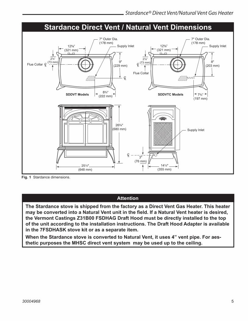
Stardance Direct Vent / Natural Vent Dimensions
26 "(680 mm)
25 "(648 mm)
14 "(355 mm)
3"(76 mm)
CL
12734Stardance dim8/07 djt
Supply Inlet
9"(229 mm)
CL
7" Outer Dia.(178 mm)
Flue Collar LC
Supply Inlet
SDDVT Models
8"(203 mm)
7" Outer Dia.(178 mm)
Flue Collar
LC
Supply Inlet
SDDVTC Models 7 ”(197 mm)
8 "(222 mm)
2 ”(73 mm)
12 ”(321 mm)
2 ”(73 mm)
12 ”(321 mm)
AttentionThe Stardance stove is shipped from the factory as a Direct Vent Gas Heater. This heater may be converted into a Natural Vent unit in the field. If a Natural Vent heater is desired, the Vermont Castings Z31B00 FSDHAG Draft Hood must be directly installed to the top of the unit according to the installation instructions. The Draft Hood Adapter is available in the 7FSDHASK stove kit or as a separate item.When the Stardance stove is converted to Natural Vent, it uses 4” vent pipe. For aes-thetic purposes the MHSC direct vent system may be used up to the ceiling.
Fig. 1 Stardance dimensions.
6
Stardance® Direct Vent/Natural Vent Gas Heater
30004968
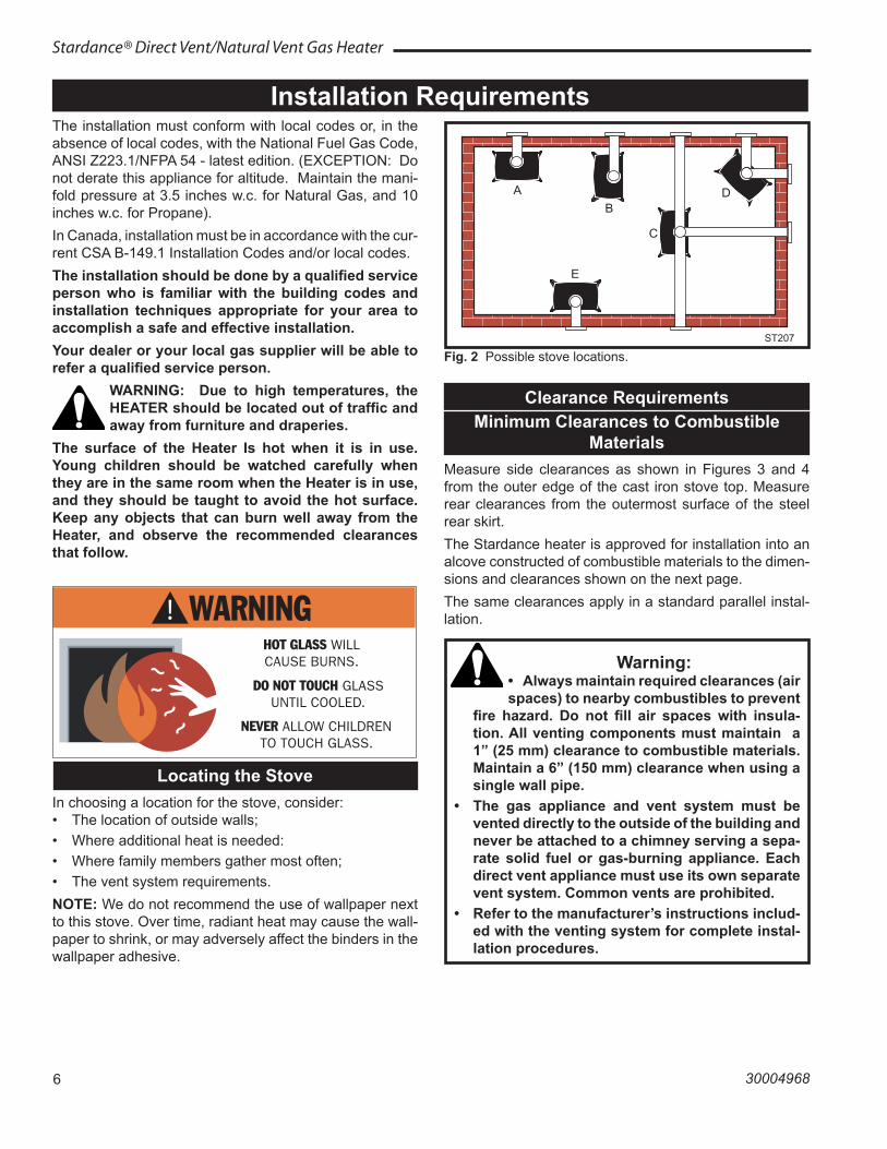
Clearance RequirementsMinimum Clearances to Combustible
MaterialsMeasure side clearances as shown in Figures 3 and 4 from the outer edge of the cast iron stove top. Measure rear clearances from the outermost surface of the steel rear skirt.The Stardance heater is approved for installation into an alcove constructed of combustible materials to the dimen-sions and clearances shown on the next page.The same clearances apply in a standard parallel instal-lation.
Installation RequirementsThe installation must conform with local codes or, in the absence of local codes, with the National Fuel Gas Code, ANSI Z223.1/NFPA 54 - latest edition. (EXCEPTION: Do not derate this appliance for altitude. Maintain the mani-fold pressure at 3.5 inches w.c. for Natural Gas, and 10 inches w.c. for Propane).In Canada, installation must be in accordance with the cur-rent CSA B-149.1 Installation Codes and/or local codes. The installation should be done by a qualified service person who is familiar with the building codes and installation techniques appropriate for your area to accomplish a safe and effective installation.Your dealer or your local gas supplier will be able to refer a qualified service person.
WARNING: Due to high temperatures, the HEATER should be located out of traffic and away from furniture and draperies.
The surface of the Heater Is hot when it is in use. Young children should be watched carefully when they are in the same room when the Heater is in use, and they should be taught to avoid the hot surface. Keep any objects that can burn well away from the Heater, and observe the recommended clearances that follow.
A
B
E
C
D
ST207aStardanceStove locations9/28/00 djt
Fig. 2 Possible stove locations.ST207
Warning:• Always maintain required clearances (air spaces) to nearby combustibles to prevent
fire hazard. Do not fill air spaces with insula-tion. All venting components must maintain a 1” (25 mm) clearance to combustible materials. Maintain a 6” (150 mm) clearance when using a single wall pipe.
• The gas appliance and vent system must be vented directly to the outside of the building and never be attached to a chimney serving a sepa-rate solid fuel or gas-burning appliance. Each direct vent appliance must use its own separate vent system. Common vents are prohibited.
• Refer to the manufacturer’s instructions includ-ed with the venting system for complete instal-lation procedures.
Locating the StoveIn choosing a location for the stove, consider:• The location of outside walls;• Where additional heat is needed:• Where family members gather most often;• The vent system requirements. NOTE: We do not recommend the use of wallpaper next to this stove. Over time, radiant heat may cause the wall-paper to shrink, or may adversely affect the binders in the wallpaper adhesive.

7
Stardance® Direct Vent/Natural Vent Gas Heater
30004968
ST128bStardanceflue centerline9/28/00 djt
CL
CL
B
D
C
A
Parallel Installation: Minimum Clearance and Flue Centerline, Direct Vent and
Natural Vent
ST128b
Stove Clearances: A: 4” (102 mm) B: 4” (102 mm)Pipe Centerlines: C: 15Z\x” (395 mm) D: 9” (229 mm)
Fig. 3 Parallel installation, minimum back and side clear-ances, and flue centerlines.
Corner Installation: Minimum Clearance and Flue Centerline,
Direct Vent and Natural Vent
ST129bStardancecorner specs9/28/00 djt
A
A
B
B
Stove Clearance: A: 4” (102 mm)Pipe Centerline: B: 14Z\x” (370 mm)
ST129b
Fig. 4 Corner installation, minimum corner clearance and flue centerline.
Wall Centerline from Floor
ST131b �Stardance �wall thimble �9/28/00 djt
A
Direct Vent Only
ST131b
Effective MinimumWall Thimble 56” (1480 mm) (MHSC Pipe)Centerline 52” (1378 mm) (Simpson Duravent Pipe)
Fig. 5 Minimum wall thimble centerline.
Wall and Ceiling Clearances
A
C
D
ST101b�Stardance�Direct Vent�Min. Clrnc�9/28/00 djt
B
ST101b
A: Rear Wall 4” (102 mm) B: Min. Clearance 45Z\v” (1154 mm)* C: Min. Alcove Height 72” (1830 mm) D: Max. Alcove Depth 48” (1220 mm) Sidewall Clearance 4” (102 mm)Fig. 6 Dimensions and clearances to ceiling or alcove.
Hearth Requirements
The Stardance Heater must be installed on rigid flooring. When the heater is installed directly on any combustible surface other than wood flooring, a metal or wood panel extending the full width and depth of the unit must be used as the hearth. There are no other hearth require-ments.
8
Stardance® Direct Vent/Natural Vent Gas Heater
30004968
Weight: Fully assembled; 202 lbs.
Gas Inlet and Manifold Pressures Natural LP (Propane) Inlet Minimum 5.5” w.c. 11.0” w.c. Inlet Maximum 14.0” w.c. 14.0” w.c. Manifold Pressure 3.5” w.c. 10” w.c.
Stardance Direct Vent / Natural VentCertified to:
ANSI Z21.88-2009 / CSA 2.33-2009Vented Gas Fireplace Heaters
The installation of your Vermont Castings stove must conform with local codes, or in the absence of local codes, with the National Fuel Gas Code ANSI Z223.1/NFPA 54 - latest edition, or CSA B149.1 Installation code. (EXCEPTION: Do not derate this appliance for altitude up to 4,500 feet (1,370m). Maintain the mani-fold pressure at 3.5” w.c. for Natural Gas and 10.0” w.c. for LP Gas.
High ElevationsInput ratings are shown in BTU per hour and are cer-tified without deration for elevations up to 4,500 feet (1,370m) above sea level.For elevations above 4,500 feet (1,370m) in USA, in-stallations must be in accordance with the current ANSI Z223.1/NFPA 54 and/or local codes having jurisdiction.In Canada, please consult provincial and/or local au-thorities having jurisdiction for installations at elevations above 4,500 feet (1,370m).
WARNING: Improper installation, adjustment, alter-ation, service or maintenance can cause injury or property damage. Refer to this manual for correct installation and operational procedures. For assis-tance or additional information consult a qualified installer, service agency, or the gas supplier.
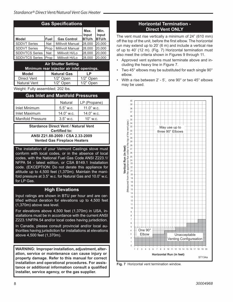
Horizontal Termination - Direct Vent ONLY
The vent must rise vertically a minimum of 24” (610 mm) off the top of the unit, before the first elbow. The horizontal run may extend up to 20’ (6 m) and include a vertical rise of up to 40’ (12 m). (Fig. 7) Horizontal termination must also meet the criteria shown in Figures 9 through 11.• Approved vent systems must terminate above and in-
cluding the heavy line in Figure 7.• Two 45° elbows may be substituted for each single 90°
elbow.• With a rise between 2’ - 5’, one 90° or two 45° elbows
may be used.
20
19
18
16
15
14
13
12
11
10
9
8
7
6
5
4
3
2
1
0
1 2 3 4 5 6 7 8 9 10 11 12 13 14 15 16 17 18 19 20
Vert
ical
Run
(in
feet
)(M
easu
red
from
the
appl
ianc
e flu
e co
llar t
o th
e to
p of
the
vent
pip
e.)
Horizontal Run (in feet)
21
22
2324
25
26
27
28
29
30
31
32
33
34
35
36
37
38
39
40
ST134a �FDV28 �Horizontal �vent run �12/3/99 djt �areas modified �1/11/00 djt
ST134a
Fig. 7 Horizontal vent termination window.
May use up to three 90° Elbows
One 90° Elbow Unacceptable
Venting Configureation
Gas Specifications Max. Min. Input Input Model Fuel Gas Control BTU/h BTU/h SDDVT Series Nat Millivolt Manual 28,000 20,000 SDDVT Series Prop Millivolt Manual 28,000 20,000 SDDVTCS Series Nat Millivolt Hi/Lo 28,000 20,000 SDDVTCS Series Prop Millivolt Hi/Lo 28,000 20,000
Air Shutter SettingMinimum rear injector air inlet openings.
Model Natural Gas LP Direct Vent 1/2” Open 1/2” Open Natural Vent 1/2” Open 1/2” Open
9
Stardance® Direct Vent/Natural Vent Gas Heater
30004968
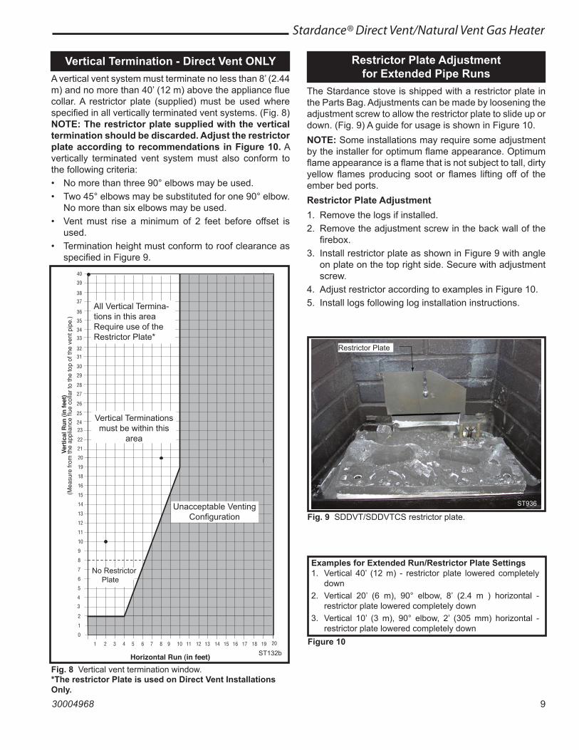
Vertical Termination - Direct Vent ONLYA vertical vent system must terminate no less than 8’ (2.44 m) and no more than 40’ (12 m) above the appliance flue collar. A restrictor plate (supplied) must be used where specified in all vertically terminated vent systems. (Fig. 8) NOTE: The restrictor plate supplied with the vertical termination should be discarded. Adjust the restrictor plate according to recommendations in Figure 10. A vertically terminated vent system must also conform to the following criteria:• No more than three 90° elbows may be used.• Two 45° elbows may be substituted for one 90° elbow.
No more than six elbows may be used.• Vent must rise a minimum of 2 feet before offset is
used.• Termination height must conform to roof clearance as
specified in Figure 9.
Vert
ical
Run
(in
feet
)(M
easu
re fr
om th
e ap
plia
nce
flue
colla
r to
the
top
of th
e ve
nt p
ipe.
)
Horizontal Run (in feet)
ST132bFDV28Vertical vent run1/08
ST132b
Fig. 8 Vertical vent termination window.*The restrictor Plate is used on Direct Vent Installations Only.
All Vertical Termina-tions in this area Require use of the Restrictor Plate*
Vertical Terminations must be within this
area
Unacceptable Venting Configuration
Restrictor Plate Adjustment for Extended Pipe Runs
The Stardance stove is shipped with a restrictor plate in the Parts Bag. Adjustments can be made by loosening the adjustment screw to allow the restrictor plate to slide up or down. (Fig. 9) A guide for usage is shown in Figure 10.NOTE: Some installations may require some adjustment by the installer for optimum flame appearance. Optimum flame appearance is a flame that is not subject to tall, dirty yellow flames producing soot or flames lifting off of the ember bed ports.Restrictor Plate Adjustment1. Remove the logs if installed.2. Remove the adjustment screw in the back wall of the
firebox.3. Install restrictor plate as shown in Figure 9 with angle
on plate on the top right side. Secure with adjustment screw.
4. Adjust restrictor according to examples in Figure 10. 5. Install logs following log installation instructions.
Figure 10
Examples for Extended Run/Restrictor Plate Settings1. Vertical 40’ (12 m) - restrictor plate lowered completely
down2. Vertical 20’ (6 m), 90° elbow, 8’ (2.4 m ) horizontal -
restrictor plate lowered completely down3. Vertical 10’ (3 m), 90° elbow, 2’ (305 mm) horizontal -
restrictor plate lowered completely down
Restrictor Plate
ST936
Fig. 9 SDDVT/SDDVTCS restrictor plate.
No Restrictor Plate
10
Stardance® Direct Vent/Natural Vent Gas Heater
30004968
When planning the installation, consider the location of the vent terminal and clearances. Some of the most com-mon clearances to keep in mind are shown in Figure 11. Important: All vent clearances must be maintained. Check your vent termination clearances against Fig-ures 11 through 13.The vent should be placed so that people cannot be burned by accidentally touching the vent surfaces when the stove is operating.The vent termination should be located where it cannot be damaged by such things as automobile doors, lawn mow-ers or snowblowers and it should be located away from areas where it could become blocked by snow, etc.Some considerations are:• Obstructions or impediments to venting.• Nearby combustible materials that could come into
contact with combustion exhaust gases.• Other nearby openings {within 12” (305 mm)} through
which exhaust gas could reenter the building.• All vegetation within 3’ (76 mm) that may interfere with
the draft.Other factors that influence where the installation will be sited include the location of outside walls, where addi-tional heat may be desired in the home, where the family members gather most regularly, and perhaps most impor-tantly, the distance limitations of the venting system.
IMPORTANTDirect Vent Only
• The horizontal termination must not be recessed into the exterior wall or siding.
• Horizontal vent runs must be level toward the vent termination.
• Clearances around the vent termination must be maintained.
• For installations using Simpson DuraVent pipe, par-allel installations with minimum wall clearance have restricted access for connecting the Horizontal Vent Cap straps to the vent pipe. See the maker’s instruc-tions for recommended installation procedures.
Vent Termination ClearancesYour stove is approved to be vented either through the side wall, or vertical through the roof.• MHSC does not require any opening for inspection of
vent pipe.• Only MHSC and Simpson DuraVent venting compo-
nents specifically approved and labelled for this stove may be used.
• Minimum clearances between vent pipes and combus-tible materials is one (1”) inch (25 mm), except where stated otherwise.
• Venting terminals shall not be recessed into a wall or siding.
• Horizontal venting must be installed on a level plane without an inclining or declining slope.
There must not be any obstruction such as bushes, gar-den sheds, fences, decks or utility buildings within 24” from the front of the termination hood.Do not locate termination hood where excessive snow or ice build up may occur. Be sure to check vent termina-tion area after snow falls, and clear to prevent accidental blockage of venting system. When using snow blowers, make sure snow is not directed towards vent termination area.
Location of Vent Termination
It is imperative the vent termination be located observing the minimum clearances as shown on this page.
11
Stardance® Direct Vent/Natural Vent Gas Heater
30004968
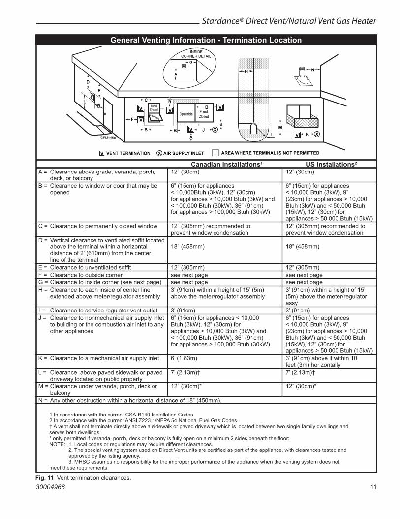
General Venting Information - Termination Location
V
X
X
X
D
E
B
B B
C
B M
B
AJ
K
F
L
VENT TERMINATION AIR SUPPLY INLET AREA WHERE TERMINAL IS NOT PERMITTED
H
I
FixedClosed
OperableOperable
FixedClosed
B
CFM145cDV Termin Location
INSIDE CORNER DETAIL
V
A
G
N
CFM145a
V
V
V
V
V
V
V
A = Clearance above grade, veranda, porch, 12” (30cm) 12” (30cm) deck, or balcony B = Clearance to window or door that may be 6” (15cm) for appliances 6” (15cm) for appliances opened < 10,000Btuh (3kW), 12” (30cm) < 10,000 Btuh (3kW), 9” for appliances > 10,000 Btuh (3kW) and (23cm) for appliances > 10,000 < 100,000 Btuh (30kW), 36” (91cm) Btuh (3kW) and < 50,000 Btuh for appliances > 100,000 Btuh (30kW) (15kW), 12” (30cm) for appliances > 50,000 Btuh (15kW) C = Clearance to permanently closed window 12” (305mm) recommended to 12” (305mm) recommended to prevent window condensation prevent window condensation D = Vertical clearance to ventilated soffit located above the terminal within a horizontal 18” (458mm) 18” (458mm) distance of 2’ (610mm) from the center line of the terminal E = Clearance to unventilated soffit 12” (305mm) 12” (305mm) F = Clearance to outside corner see next page see next page G = Clearance to inside corner (see next page) see next page see next page H = Clearance to each inside of center line 3’ (91cm) within a height of 15’ (5m) 3’ (91cm) within a height of 15’ extended above meter/regulator assembly above the meter/regulator assembly (5m) above the meter/regulator assy I = Clearance to service regulator vent outlet 3’ (91cm) 3’ (91cm) J = Clearance to nonmechanical air supply inlet 6” (15cm) for appliances < 10,000 6” (15cm) for appliances to building or the combustion air inlet to any Btuh (3kW), 12” (30cm) for < 10,000 Btuh (3kW), 9” other appliances appliances > 10,000 Btuh (3kW) and (23cm) for appliances > 10,000 < 100,000 Btuh (30kW), 36” (91cm) Btuh (3kW) and < 50,000 Btuh for appliances > 100,000 Btuh (30kW) (15kW), 12” (30cm) for appliances > 50,000 Btuh (15kW) K = Clearance to a mechanical air supply inlet 6’ (1.83m) 3’ (91cm) above if within 10 feet (3m) horizontally L = Clearance above paved sidewalk or paved 7’ (2.13m)† 7’ (2.13m)† driveway located on public property M = Clearance under veranda, porch, deck or 12” (30cm)* 12” (30cm)* balcony N = Any other obstruction within a horizontal distance of 18” (450mm).
1 In accordance with the current CSA-B149 Installation Codes 2 In accordance with the current ANSI Z223.1/NFPA 54 National Fuel Gas Codes † A vent shall not terminate directly above a sidewalk or paved driveway which is located between two single family dwellings and serves both dwellings * only permitted if veranda, porch, deck or balcony is fully open on a minimum 2 sides beneath the floor: NOTE: 1. Local codes or regulations may require different clearances. 2. The special venting system used on Direct Vent units are certified as part of the appliance, with clearances tested and approved by the listing agency. 3. MHSC assumes no responsibility for the improper performance of the appliance when the venting system does not meet these requirements.
Canadian Installations1 US Installations2
Fig. 11 Vent termination clearances.
12
Stardance® Direct Vent/Natural Vent Gas Heater
30004968
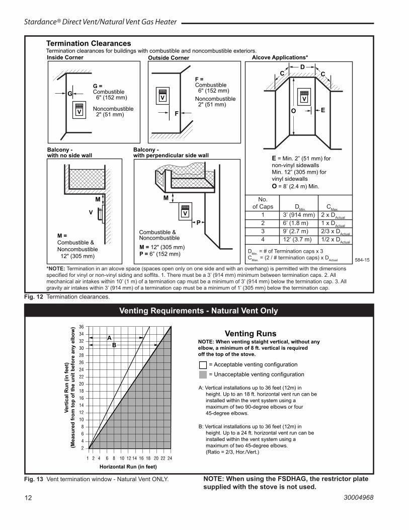
Fig. 12 Termination clearances.
Venting Requirements - Natural Vent Only
FP567
NVBR/NVBC VENTING RUNS
11/12/97
Venting Runs
Horizontal Run (in feet)
Ver
tica
l Ru
n (
in f
eet)
(Mea
sure
d f
rom
to
p o
f th
e u
nit
bef
ore
an
y el
bo
w)
A: Vertical installations up to 36 feet (12m) in height. Up to an 18 ft. horizontal vent run can be installed within the vent system using a maximum of two 90-degree elbows or four 45-degree elbows.
B: Vertical installations up to 36 feet (12m) in height. Up to a 24 ft. horizontal vent run can be installed within the vent system using a maximum of two 45-degree elbows. (Ratio = 2/3, Hor./Vert.)
= Acceptable venting configuration
= Unacceptable venting configuration
AB
NOTE: When venting staight vertical, without anyelbow, a minimum of 8 ft. vertical is requiredoff the top of the stove.
Fig. 13 Vent termination window - Natural Vent ONLY. NOTE: When using the FSDHAG, the restrictor plate supplied with the stove is not used.
Outside Corner Inside Corner
Termination Clearances Termination clearances for buildings with combustible and noncombustible exteriors.
G = Combustible 6" (152 mm) Noncombustible 2" (51 mm)
F = Combustible 6" (152 mm) Noncombustible 2" (51 mm)
G
Balcony - with no side wall
M = Combustible & Noncombustible 12" (305 mm)
M
Balcony - with perpendicular side wall
M = 12" (305 mm)P = 6” (152 mm)
M
F
Alcove Applications*
C D
C
EV
V
Combustible & Noncombustible
E = Min. 2” (51 mm) for non-vinyl sidewallsMin. 12” (305 mm) forvinyl sidewallsO = 8’ (2.4 m) Min.
O
P
V
V
V
584-15
No. of Caps DMin. CMax.
1 3’ (914 mm) 2 x DActual
2 6’ (1.8 m) 1 x DActual
3 9’ (2.7 m) 2/3 x DActual
4 12’ (3.7 m) 1/2 x DActual
DMin. = # of Termination caps x 3CMax. = (2 / # termination caps) x DActual
*NOTE: Termination in an alcove space (spaces open only on one side and with an overhang) is permitted with the dimensions specified for vinyl or non-vinyl siding and soffits. 1. There must be a 3’ (914 mm) minimum between termination caps. 2. All mechanical air intakes within 10’ (1 m) of a termination cap must be a minimum of 3’ (914 mm) below the termination cap. 3. All gravity air intakes within 3’ (914 mm) of a termination cap must be a minimum of 1’ (305 mm) below the termination cap.
13
Stardance® Direct Vent/Natural Vent Gas Heater
30004968
Venting Requirements and Options - Direct Vent ONLY
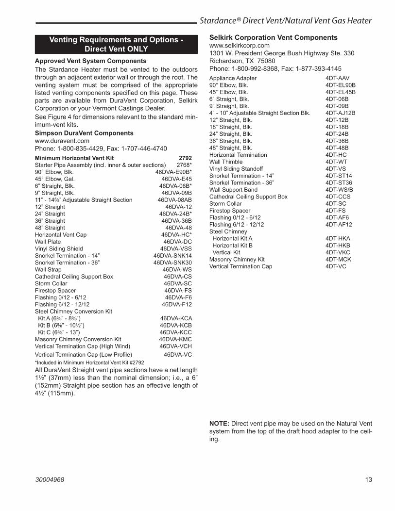
Approved Vent System ComponentsThe Stardance Heater must be vented to the outdoors through an adjacent exterior wall or through the roof. The venting system must be comprised of the appropriate listed venting components specified on this page. These parts are available from DuraVent Corporation, Selkirk Corporation or your Vermont Castings Dealer.See Figure 4 for dimensions relevant to the standard min-imum-vent kits.Simpson DuraVent Componentswww.duravent.comPhone: 1-800-835-4429, Fax: 1-707-446-4740Minimum Horizontal Vent Kit 2792Starter Pipe Assembly (incl. inner & outer sections) 2768*90° Elbow, Blk. 46DVA-E90B*45° Elbow, Gal. 46DVA-E456” Straight, Blk. 46DVA-06B*9” Straight, Blk. 46DVA-09B11” - 14⁵\₈” Adjustable Straight Section 46DVA-08AB12” Straight 46DVA-1224” Straight 46DVA-24B*36” Straight 46DVA-36B48” Straight 46DVA-48Horizontal Vent Cap 46DVA-HC*Wall Plate 46DVA-DCVinyl Siding Shield 46DVA-VSSSnorkel Termination - 14” 46DVA-SNK14Snorkel Termination - 36” 46DVA-SNK30Wall Strap 46DVA-WSCathedral Ceiling Support Box 46DVA-CSStorm Collar 46DVA-SCFirestop Spacer 46DVA-FSFlashing 0/12 - 6/12 46DVA-F6Flashing 6/12 - 12/12 46DVA-F12Steel Chimney Conversion Kit Kit A (6⁵\₈” - 8⁵\₈”) 46DVA-KCA Kit B (6⁵\₈” - 10Z\x”) 46DVA-KCB Kit C (6⁵\₈” - 13”) 46DVA-KCCMasonry Chimney Conversion Kit 46DVA-KMCVertical Termination Cap (High Wind) 46DVA-VCHVertical Termination Cap (Low Profile) 46DVA-VC*Included in Minimum Horizontal Vent Kit #2792All DuraVent Straight vent pipe sections have a net length 1Z\x” (37mm) less than the nominal dimension; i.e., a 6” (152mm) Straight pipe section has an effective length of 4Z\x” (115mm).
Selkirk Corporation Vent Componentswww.selkirkcorp.com1301 W. President George Bush Highway Ste. 330Richardson, TX 75080Phone: 1-800-992-8368, Fax: 1-877-393-4145Appliance Adapter 4DT-AAV90° Elbow, Blk. 4DT-EL90B45° Elbow, Blk. 4DT-EL45B6” Straight, Blk. 4DT-06B9” Straight, Blk. 4DT-09B4” - 10” Adjustable Straight Section Blk. 4DT-AJ12B12” Straight, Blk. 4DT-12B18” Straight, Blk. 4DT-18B24” Straight, Blk. 4DT-24B36” Straight, Blk. 4DT-36B48” Straight, Blk. 4DT-48BHorizontal Termination 4DT-HCWall Thimble 4DT-WTVinyl Siding Standoff 4DT-VSSnorkel Termination - 14” 4DT-ST14Snorkel Termination - 36” 4DT-ST36Wall Support Band 4DT-WS/BCathedral Ceiling Support Box 4DT-CCSStorm Collar 4DT-SCFirestop Spacer 4DT-FSFlashing 0/12 - 6/12 4DT-AF6Flashing 6/12 - 12/12 4DT-AF12Steel Chimney Horizontal Kit A 4DT-HKA Horizontal Kit B 4DT-HKB Vertical Kit 4DT-VKCMasonry Chimney Kit 4DT-MCKVertical Termination Cap 4DT-VC
NOTE: Direct vent pipe may be used on the Natural Vent system from the top of the draft hood adapter to the ceil-ing.
14
Stardance® Direct Vent/Natural Vent Gas Heater
30004968
MHSC Vent ComponentsThe following kits are available to meet the needs of most installations. All pipe has a 7” outer diameter and includes a 4” diameter inner section. A (CG) designation indicates the part is finished in Charcoal Gray paint. Consult your dealer about other vent parts that may be appropriate to complete the installation. Min. Through the Wall Vent Kit 7TFSSK(1) 90-Degree Elbow (CG)(1) 24” Straight pipe (CG)(1) 24” - 42” Adjustable Straight Pipe(1) Side Wall Termination(1) Firestop(1) Zero-clearance sleeve(1) Hardware package(1) Finishing plate (CG)(1) Finishing collar (CG)(4) Charcoal Gray flue pipe ringsStarter Kit for Below Grade Installation 7TDVSKS(1) Snorkel Termination (7TDVSNORK)Vertical Termination Kit, 1/12-6/12 Pitch 7TDVSKVA(1) Combination Horizontal Offset / Roof Support(1) Vertical Termination(1) Storm Collar(1) 1/12-6/12 Flashing(1) Finishing Plate (CG)(1) Finishing Collar (CG)(1) Polished Brass Flue Pipe Ring(1) Hardware PackageVertical Termination Kit, 7/12-12/12 Pitch 7TDVSKVB(1) 7/12 - 12/12 Flashingand all of the other Vertical Termination parts. Vertical Termination, Flat Roof 7DVSKVF(1) Flat Flashingand all of the other Vertical Termination parts.
Twist Lock 12” Straight Pipe (CG) 7TFSDVP12(1) 12” Non-adjustable PipeTwist Lock 12”-18” Straight Pipe (CG) 7TFSDVP1218(1) 12” - 18” Adjustable PipeTwist Lock 24” Straight Pipe (CG) 7TFSDVP24(1) 24” Non-adjustable PipeTwist Lock 48” Straight Pipe (CG) 7TFSDVP48(1) 48” Nonadjustable PipeTwist Lock 45-Degree Elbow (CG) 7TFSDVT45for vertical offsets(1) 45-degree ElbowDraft Hood Adapter FSDHAGNV Stove Kit 7FSSK(1) 7” Diameter Polished Brass Trim Ring(1) 48” Nonadjustable Pipe (CG)(1) 24” Nonadjustable Pipe (CG)(1) Finishing Plate(1) Finishing Collar (CG)(1) 90 Degree Elbow (CG)Stove Kit 7FSDHASKIncludes all parts in the 7FSSK plus the Draft Hood Adapter FS-DHAGCombination Offset/Roof Support 7DVCSAttic Insulation Shield 7DVAIS7” Charcoal Gray Pipe Rings, (4) 7FSDRG7” Polished Brass Pipe Rings (4) 7FSDRPWall Thimble 942G
NOTE: Direct vent pipe may be used on the Natural Vent system from the top of the draft hood adapter to the ceil-ing.
15
Stardance® Direct Vent/Natural Vent Gas Heater
30004968
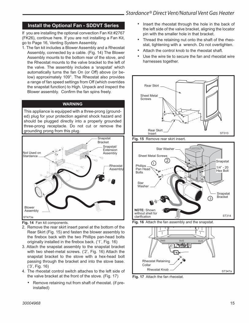
Install the Optional Fan - SDDVT SeriesIf you are installing the optional convection Fan Kit #2767 (FK26), continue here. If you are not installing a Fan Kit, go to Page 16, Venting System Assembly.1. The fan kit includes a Blower Assembly and a Rheostat
Assembly, connected by a cable. (Fig. 14) The Blower Assembly mounts to the bottom rear of the stove, and the Rheostat mounts to the valve bracket to the left of the valve. The assembly includes a ‘snapstat’ which automatically turns the fan On (or Off) above (or be-low) approximately 109°. The Rheostat also provides a range of fan speed settings from Off (which overrides the snapstat function) to High. Unpack and inspect the Blower assembly. Confirm the fan spins freely.
WARNING
This appliance is equipped with a three-prong (ground-ed) plug for your protection against shock hazard and should be plugged directly into a properly grounded three-prong receptacle. Do not cut or remove the grounding prong from this plug.
• Insert the rheostat through the hole in the back of the left side of the valve bracket, aligning the locator pin with the smaller hole in that bracket.
• Thread the retaining nut onto the shaft of the rheo-stat, tightening with a wrench. Do not overtighten.
• Attach the control knob to the rheostat shaft.• Use the wire tie to secure the fan and rheostat wire
harnesses together.
ST473aFan parts#2767 FK269/29/00
Not Used on Stardance
Snapstat Bracket
Snapstat/Extension Assembly
Rheostat Assembly
Blower Assembly
ST473a
Fig. 14 Fan kit components.2. Remove the rear skirt insert panel at the bottom of the
Rear Skirt (Fig. 15) and fasten the blower assembly to the firebox back with the two Phillips pan-head bolts originally installed in the firebox back. (‘1’, Fig. 16)
3. Attach the snapstat assembly to the snapstat bracket with two sheet-metal screws. (‘2’, Fig. 16) Attach the snapstat bracket to the stove with a hex-head bolt passing through the bracket and into the stove base. (‘3’, Fig. 16)
4. The rheostat control switch attaches to the left side of the valve bracket at the front of the stove. (Fig. 17) • Remove retaining nut from shaft of rheostat. (if pre-
installed)
ST313 �fk26 �install fan kit �rear skirt insert �1/24/00
Rear Skirt
Sheet Metal Screws
Rear Skirt Insert ST313
Fig. 15 Remove rear skirt insert.
ST314 �Fk26ce �attach fan �1/24/00
Star Washer
Sheet Metal Screws
Phillips Pan Head Bolts
Star Washer
NOTE: Shown without shell for clarification
Snapstat Bracket
Snapstat
1/4” - 20 Hex Bolt
3
21
ST314
Fig. 16 Attach the fan assembly and the snapstat.
ST347a�JUV�FK28 �rheostat install�9/21/00
Rheostat Retaining Collar
Rheostat Knob ST347a
Fig. 17 Attach the fan rheostat.
16
Stardance® Direct Vent/Natural Vent Gas Heater
30004968
Venting System Assemlby - Direct VentGeneral Information
The Stardance is approved for installation only with the vent components listed on Pages 13 & 14. Follow the vent component instructions exactly.For U.S. installations: The venting system must conform with local codes and/or the current National Fuel Gas Code, ANSI Z223.1/NFPA 54.For Canadian installations: The venting system must conform to the current CSA B149.1 installation code.
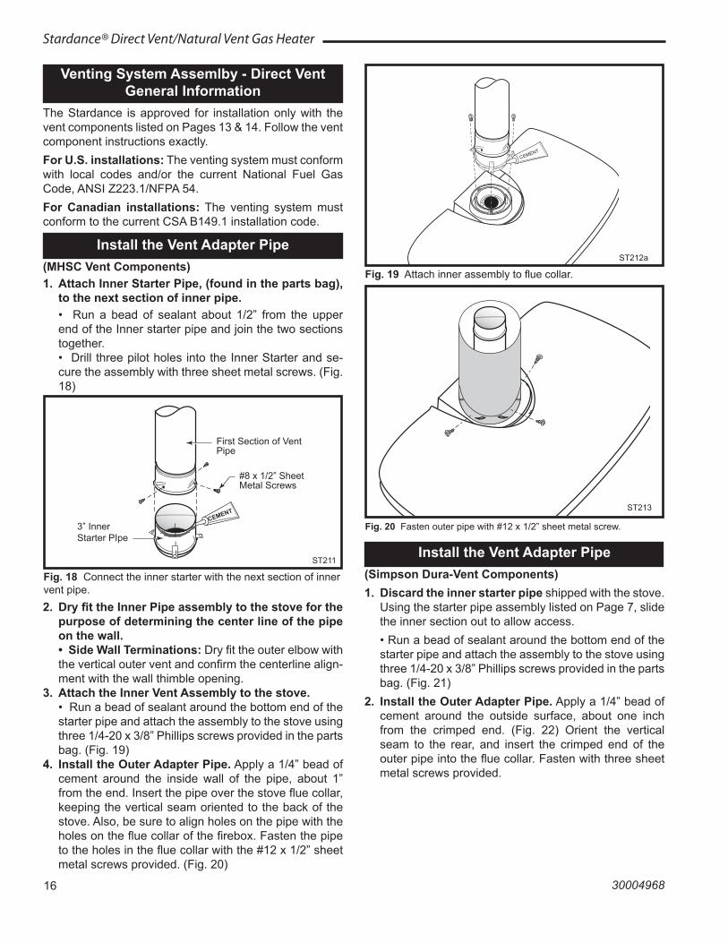
Install the Vent Adapter Pipe (MHSC Vent Components)1. Attach Inner Starter Pipe, (found in the parts bag),
to the next section of inner pipe. • Run a bead of sealant about 1/2” from the upper
end of the Inner starter pipe and join the two sections together.
• Drill three pilot holes into the Inner Starter and se-cure the assembly with three sheet metal screws. (Fig. 18)
ST211attach inner pipeto next section12/4/99 djt
CEMENT
First Section of Vent Pipe
3” Inner Starter PIpe
#8 x 1/2” Sheet Metal Screws
ST211
Fig. 18 Connect the inner starter with the next section of inner vent pipe.
ST212aattach inner assyno restrictor plate6/07 djt
CEMENT
ST212a
Fig. 19 Attach inner assembly to flue collar.
Install the Vent Adapter Pipe (Simpson Dura-Vent Components)1. Discard the inner starter pipe shipped with the stove.
Using the starter pipe assembly listed on Page 7, slide the inner section out to allow access.
• Run a bead of sealant around the bottom end of the starter pipe and attach the assembly to the stove using three 1/4-20 x 3/8” Phillips screws provided in the parts bag. (Fig. 21)
2. Install the Outer Adapter Pipe. Apply a 1/4” bead of cement around the outside surface, about one inch from the crimped end. (Fig. 22) Orient the vertical seam to the rear, and insert the crimped end of the outer pipe into the flue collar. Fasten with three sheet metal screws provided.
ST213 �install outer adpater �12/6/99 djt
ST213
Fig. 20 Fasten outer pipe with #12 x 1/2” sheet metal screw.
2. Dry fit the Inner Pipe assembly to the stove for the purpose of determining the center line of the pipe on the wall.
• Side Wall Terminations: Dry fit the outer elbow with the vertical outer vent and confirm the centerline align-ment with the wall thimble opening.
3. Attach the Inner Vent Assembly to the stove. • Run a bead of sealant around the bottom end of the
starter pipe and attach the assembly to the stove using three 1/4-20 x 3/8” Phillips screws provided in the parts bag. (Fig. 19)
4. Install the Outer Adapter Pipe. Apply a 1/4” bead of cement around the inside wall of the pipe, about 1” from the end. Insert the pipe over the stove flue collar, keeping the vertical seam oriented to the back of the stove. Also, be sure to align holes on the pipe with the holes on the flue collar of the firebox. Fasten the pipe to the holes in the flue collar with the #12 x 1/2” sheet metal screws provided. (Fig. 20)
17
Stardance® Direct Vent/Natural Vent Gas Heater
30004968
ST355bdura ventattach inner assyno restrictor plate6/07 djt
CEMENT
1/4-20 x 3/8 Phillips Screws
Inner Adapter Pipe
ST355b
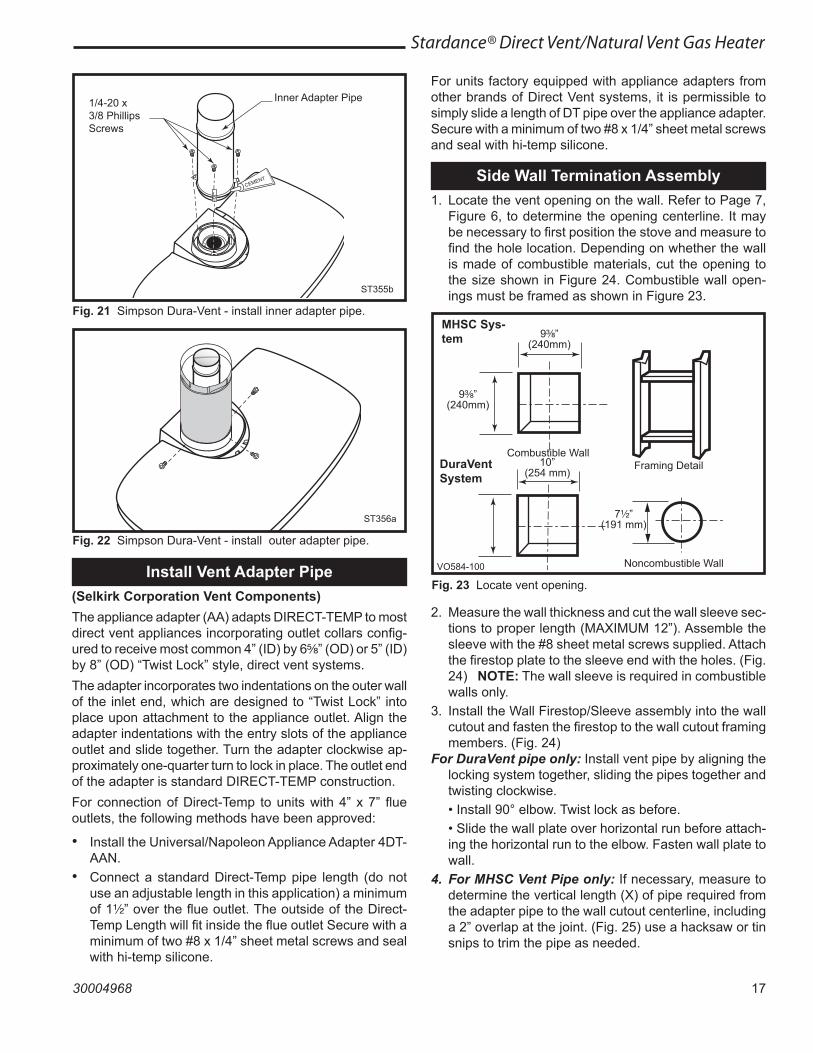
Fig. 21 Simpson Dura-Vent - install inner adapter pipe.
ST356 �dura vent �attach outer assy �4/7/00 djt
ST356a
Fig. 22 Simpson Dura-Vent - install outer adapter pipe.
Side Wall Termination Assembly1. Locate the vent opening on the wall. Refer to Page 7,
Figure 6, to determine the opening centerline. It may be necessary to first position the stove and measure to find the hole location. Depending on whether the wall is made of combustible materials, cut the opening to the size shown in Figure 24. Combustible wall open-ings must be framed as shown in Figure 23.
VO584-100Vent Opening2/99 djt
MHSC Sys-tem 9C\₈”
(240mm)
9C\₈”(240mm)
Combustible WallFraming DetailDuraVent
System10”
(254 mm)
7Z\x”(191 mm)
Noncombustible WallVO584-100
Fig. 23 Locate vent opening.Install Vent Adapter Pipe
(Selkirk Corporation Vent Components)The appliance adapter (AA) adapts DIRECT-TEMP to most direct vent appliances incorporating outlet collars config-ured to receive most common 4” (ID) by 6⁵\₈” (OD) or 5” (ID) by 8” (OD) “Twist Lock” style, direct vent systems.The adapter incorporates two indentations on the outer wall of the inlet end, which are designed to “Twist Lock” into place upon attachment to the appliance outlet. Align the adapter indentations with the entry slots of the appliance outlet and slide together. Turn the adapter clockwise ap-proximately one-quarter turn to lock in place. The outlet end of the adapter is standard DIRECT-TEMP construction.For connection of Direct-Temp to units with 4” x 7” flue outlets, the following methods have been approved:
• Install the Universal/Napoleon Appliance Adapter 4DT-AAN.
• Connect a standard Direct-Temp pipe length (do not use an adjustable length in this application) a minimum of 1Z\x” over the flue outlet. The outside of the Direct-Temp Length will fit inside the flue outlet Secure with a minimum of two #8 x 1/4” sheet metal screws and seal with hi-temp silicone.
For units factory equipped with appliance adapters from other brands of Direct Vent systems, it is permissible to simply slide a length of DT pipe over the appliance adapter. Secure with a minimum of two #8 x 1/4” sheet metal screws and seal with hi-temp silicone.
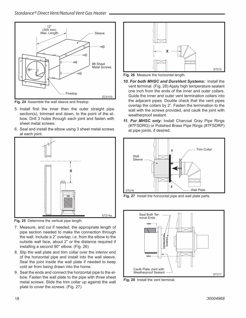
2. Measure the wall thickness and cut the wall sleeve sec-tions to proper length (MAXIMUM 12”). Assemble the sleeve with the #8 sheet metal screws supplied. Attach the firestop plate to the sleeve end with the holes. (Fig. 24) NOTE: The wall sleeve is required in combustible walls only.
3. Install the Wall Firestop/Sleeve assembly into the wall cutout and fasten the firestop to the wall cutout framing members. (Fig. 24)
For DuraVent pipe only: Install vent pipe by aligning the locking system together, sliding the pipes together and twisting clockwise.
• Install 90° elbow. Twist lock as before. • Slide the wall plate over horizontal run before attach-
ing the horizontal run to the elbow. Fasten wall plate to wall.
4. For MHSC Vent Pipe only: If necessary, measure to determine the vertical length (X) of pipe required from the adapter pipe to the wall cutout centerline, including a 2” overlap at the joint. (Fig. 25) use a hacksaw or tin snips to trim the pipe as needed.
18
Stardance® Direct Vent/Natural Vent Gas Heater
30004968
5. Install first the inner then the outer straight pipe section(s), trimmed end down, to the point of the el-bow. Drill 3 holes through each joint and fasten with sheet metal screws.
6. Seal and install the elbow using 3 sheet metal screws at each joint.
ZCS103 �Zero Clearance Sleeve �& Firestop �12/6/99 djt
12”(305 mm)
Max. Length Sleeve
#8 Sheet Metal Screws
FirestopZCS103
Fig. 24 Assemble the wall sleeve and firestop.
ST214a �measure vertical vent �12/6/99 djt
X
ST214a
Fig. 25 Determine the vertical pipe length.
10. For both MHSC and DuraVent Systems: Install the vent terminal. (Fig. 28) Apply high temperature sealant one inch from the ends of the inner and outer collars. Guide the inner and outer vent termination collars into the adjacent pipes. Double check that the vent pipes overlap the collars by 2”. Fasten the termination to the wall with the screws provided, and caulk the joint with weatherproof sealant.
11. For MHSC only: Install Charcoal Gray Pipe Rings (#7FSDRG) or Polished Brass Pipe Rings (#7FSDRP) at pipe joints, if desired.
ST215 �measure thru wall �12/6/99 djt
X
ST215
Fig. 26 Measure the horizontal length.
ST216 �install pipe thru wall �12/6/99 djt
Wall Sleeve
Trim Collar
Wall PlateST216
Fig. 27 Install the horizontal pipe and wall plate parts.
7. Measure, and cut if needed, the appropriate length of pipe section needed to make the connection through the wall. Include a 2” overlap; i.e. from the elbow to the outside wall face, about 2” or the distance required if installing a second 90° elbow. (Fig. 26)
8. Slip the wall plate and trim collar over the interior end of the horizontal pipe and install into the wall sleeve. Seal the joint inside the wall plate if needed to keep cold air from being drawn into the home.
9. Seal the ends and connect the horizontal pipe to the el-bow. Fasten the wall plate to the pipe with three sheet metal screws. Slide the trim collar up against the wall plate to cover the screws. (Fig. 27)
ST217 �install wall terminal �12/6/99 djt
Seal Both Ter-minal Ends
Caulk Plate Joint with Weatherproof Sealant
ST217
Fig. 28 Install the vent terminal.
19
Stardance® Direct Vent/Natural Vent Gas Heater
30004968
ST218install snorkel12/6/99 djt
4”
Waterproof Seal Around PIpeFirestop
Wall Screws and Anchors
Snorkel Termination Cap
Drain
Window Well
ST218a
Fig. 29 Snorkel kit installation.
ST219 �snorkel detail �12/6/99 djt
Recessed Wall
Sheet Metal Screws and Bracket
Wall Screws and Anchor
Waterproof Seal Around Pipe
Firestop
Finishing Collar
7” Pipe
Wall PlateST219
Fig. 30 Use extension brackets to mount snorkel against recessed wall.
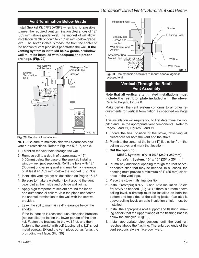
Vent Termination Below GradeInstall Snorkel Kit #7FSDVSKS when it is not possible to meet the required vent termination clearances of 12” (305 mm) above grade level. The snorkel kit will allow installation depth of down to 7” (178 mm) below grade level. The seven inches is measured from the center of the horizontal vent pipe as it penetrates the wall. If the venting system is installed below grade, a window well must be installed with adequate and proper drainage. (Fig. 29)
Vertical (Through the Roof) Vent Assembly
Note that all vertically terminated installations must include the restrictor plate included with the stove. Refer to Page 9, Figure 8.Make certain the vent system conforms to all other re-quirements for vertical termination as specified on Page 8.This installation will require you to first determine the roof pitch and use the appropriate vent components. Refer to Pages 9 and 11, Figures 8 and 11.1. Locate the final position of the stove, observing all
clearances for both the vent and the stove.2. Plumb to the center of the inner (4”) flue collar from the
ceiling above, and mark that location.3. Cut the opening: MHSC System: 9C\₈” x 9C\₈” (240 x 240mm) DuraVent System: 10” x 10” (254 x 254mm)4. Plumb any additional opening through the roof or oth-
er construction that may be needed. In all cases, the opening must provide a minimum of 1” (25 mm) clear-ance to the vent pipe.
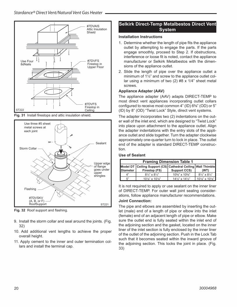
5. Place the stove in its final position.6. Install firestop(s) #7DVFS and Attic Insulation Shield
#7DVAIS as needed. (Fig. 31) If there is a room above ceiling level, a firestop must be installed on both the bottom and top sides of the ceiling joists. If an attic is above ceiling level, an attic insulation shield must be installed.
7. Install the appropriate roof support and flashing, mak-ing certain that the upper flange of the flashing base is below the shingles. (Fig. 32)
8. Install appropriate pipe sections until the vent run reaches above the flashing. The enlarged ends of the vent sections always face downward.
NOTE: Be sure to maintain side wall clearances and vent run restrictions. Refer to Figures 5, 6, 7, and 8.1. Establish the vent hole through the wall.2. Remove soil to a depth of approximately 16”
(400mm) below the base of the snorkel. Install a window well (not supplied). Refill the hole with 12” (305mm) of coarse gravel and maintain a clearance of at least 4” (102 mm) below the snorkel. (Fig. 33)
3. Install the vent system as described on Pages 15-18.4. Be sure to make a watertight joint around the vent
pipe joint at the inside and outside wall joints.5. Apply high temperature sealant around the inner
and outer snorkel collars. Join the pipes and fasten the snorkel termination to the wall with the screws provided.
6. Level the soil to maintain a 4” clearance below the snorkel.
If the foundation is recessed, use extension brackets (not supplied) to fasten the lower portion of the snor-kel. Fasten the brackets to the wall first, and then fasten to the snorkel with self-tapping #8 x 1/2” sheet metal screws. Extend the vent pipes out as far as the protruding wall face. (Fig. 30)
20
Stardance® Direct Vent/Natural Vent Gas Heater
30004968
ST222vent thru ceiling12/99
#7DVAIS Attic Insulation Shield
#7DVFS Firestop in Upper Floor
#7DVFSFirestop in Ceiling
Use Four 8dNails
ST222
Fig. 31 Install firestops and attic insulation shield.
ST221 �vent thru roof �12/99
Sealant
Storm Collar
Use three #5 sheet metal screws at each joint
Upper edge of flange goes under upper shingles
Flashing
#7DVSKV(A, B, or F)RoofSupport ST221
Fig. 32 Roof support and flashing.
Selkirk Direct-Temp Metalbestos Direct Vent System
Installation Instructions1. Determine whether the length of pipe fits the appliance
outlet by attempting to engage the parts. If the parts engage smoothly, proceed to Step 2. If obstructions, interference or loose fit is noted, contact the appliance manufacturer or Selkirk Metalbestos with the dimen-sions of the appliance outlet.
2. Slide the length of pipe over the appliance outlet a minimum of 1Z\x” and screw to the appliance outlet col-lar using a minimum of two (2) #8 x 1/4” sheet metal screws.
Appliance Adapter (AAV)The appliance adapter (AAV) adapts DIRECT-TEMP to most direct vent appliances incorporating outlet collars configured to receive most common 4” (ID) 6⁵\₈” (OD) or 5” (ID) by 8” (OD) “Twist Lock” Style, direct vent systems.The adapter incorporates two (2) indentations on the out-er wall of the inlet end, which are designed to “Twist Lock” into place upon attachment to the appliance outlet. Align the adapter indentations with the entry slots of the appli-ance outlet and slide together. Turn the adapter clockwise approximately one-quarter turn to lock in place. The outlet end of the adapter is standard DIRECT-TEMP construc-tion.Use of Sealant
Framing Dimension Table 1 Model DT Ceiling Support (CS) Cathedral Ceiling Wall Thimble Diameter Firestop (FS) Support CCS) (WT) 4” 8Z\v” x 8Z\v” 10⁵\₈” x 10⁵\₈” 8Z\v” x 8Z\v” 5” 10Z\₈” x 10Z\₈” 14Z\x” x 14Z\x” 10Z\₈” x 10Z\₈”
9. Install the storm collar and seal around the joints. (Fig. 32)
10. Add additional vent lengths to achieve the proper overall height.
11. Apply cement to the inner and outer termination col-lars and install the terminal cap.
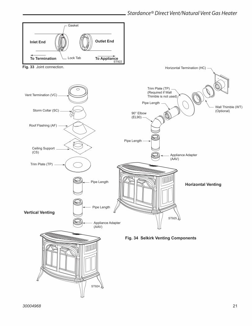
It is not required to apply or use sealant on the inner liner of DIRECT-TEMP. For outer wall joint sealing consider-ations, follow appliance manufacturer recommendations.Joint Connection:The pipe and elbows are assembled by inserting the out-let (male) end of a length of pipe or elbow into the inlet (female) end of an adjacent length of pipe or elbow. Make sure the outlet end is fully seated within the inlet end of the adjoining section and the gasket, located on the inner liner of the inlet section is fully enclosed by the inner liner of the outlet of the adjoining section. Push in the Lock Tab such that it becomes seated within the inward groove of the adjoining section. This locks the joint in place. (Fig. 33)
21
Stardance® Direct Vent/Natural Vent Gas Heater
30004968
Vent Termination (VC)
Storm Collar (SC)
Roof Flashing (AF)
Ceiling Support (CS)
Trim Plate (TP)
Pipe Length
Pipe Length
Appliance Adapter (AAV)
ST924
Vertical Venting
Gasket
Lock Tab
Inlet End Outlet End
ST922To Termination To Appliance
Fig. 33 Joint connection.
Fig. 34 Selkirk Venting Components
Pipe Length
Appliance Adapter (AAV)
90° Elbow (EL90)
Pipe Length
Trim Plate (TP)(Required if Wall Thimble is not used)
Wall Thimble (WT)(Optional)
Horizontal Termination (HC)
ST925
Horizontal Venting
22
Stardance® Direct Vent/Natural Vent Gas Heater
30004968
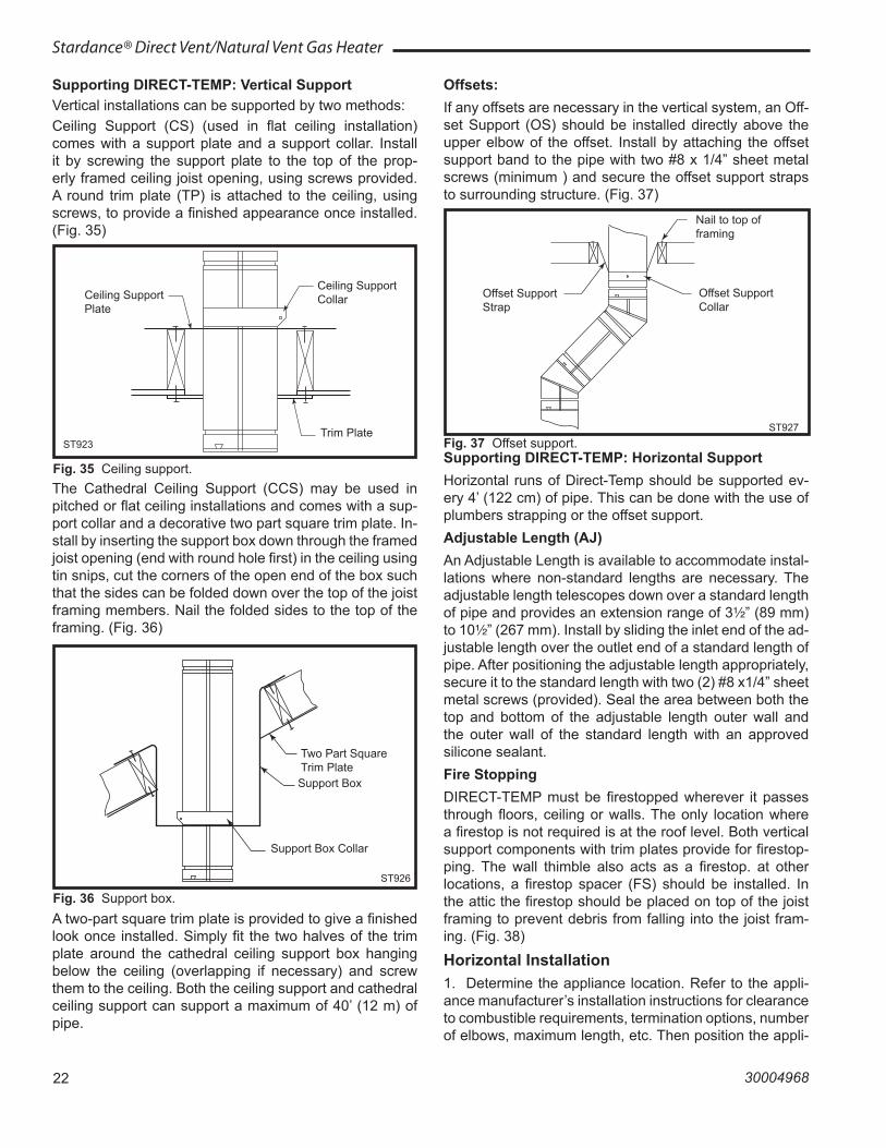
Supporting DIRECT-TEMP: Vertical SupportVertical installations can be supported by two methods:Ceiling Support (CS) (used in flat ceiling installation) comes with a support plate and a support collar. Install it by screwing the support plate to the top of the prop-erly framed ceiling joist opening, using screws provided. A round trim plate (TP) is attached to the ceiling, using screws, to provide a finished appearance once installed. (Fig. 35)
Ceiling Support Plate
Ceiling Support Collar
Trim PlateST923
Fig. 35 Ceiling support.The Cathedral Ceiling Support (CCS) may be used in pitched or flat ceiling installations and comes with a sup-port collar and a decorative two part square trim plate. In-stall by inserting the support box down through the framed joist opening (end with round hole first) in the ceiling using tin snips, cut the corners of the open end of the box such that the sides can be folded down over the top of the joist framing members. Nail the folded sides to the top of the framing. (Fig. 36)
Two Part Square Trim PlateSupport Box
Support Box Collar
ST926
Fig. 36 Support box.A two-part square trim plate is provided to give a finished look once installed. Simply fit the two halves of the trim plate around the cathedral ceiling support box hanging below the ceiling (overlapping if necessary) and screw them to the ceiling. Both the ceiling support and cathedral ceiling support can support a maximum of 40’ (12 m) of pipe.
Offsets:If any offsets are necessary in the vertical system, an Off-set Support (OS) should be installed directly above the upper elbow of the offset. Install by attaching the offset support band to the pipe with two #8 x 1/4” sheet metal screws (minimum ) and secure the offset support straps to surrounding structure. (Fig. 37)
Nail to top of framing
Offset Support Strap
Offset Support Collar
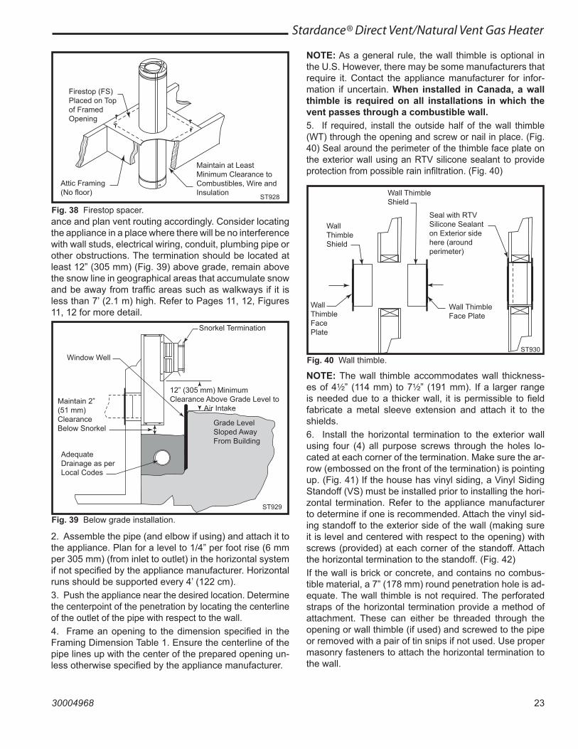
ST927Fig. 37 Offset support.Supporting DIRECT-TEMP: Horizontal SupportHorizontal runs of Direct-Temp should be supported ev-ery 4’ (122 cm) of pipe. This can be done with the use of plumbers strapping or the offset support.Adjustable Length (AJ)An Adjustable Length is available to accommodate instal-lations where non-standard lengths are necessary. The adjustable length telescopes down over a standard length of pipe and provides an extension range of 3Z\x” (89 mm) to 10Z\x” (267 mm). Install by sliding the inlet end of the ad-justable length over the outlet end of a standard length of pipe. After positioning the adjustable length appropriately, secure it to the standard length with two (2) #8 x1/4” sheet metal screws (provided). Seal the area between both the top and bottom of the adjustable length outer wall and the outer wall of the standard length with an approved silicone sealant.Fire StoppingDIRECT-TEMP must be firestopped wherever it passes through floors, ceiling or walls. The only location where a firestop is not required is at the roof level. Both vertical support components with trim plates provide for firestop-ping. The wall thimble also acts as a firestop. at other locations, a firestop spacer (FS) should be installed. In the attic the firestop should be placed on top of the joist framing to prevent debris from falling into the joist fram-ing. (Fig. 38)
Horizontal Installation1. Determine the appliance location. Refer to the appli-ance manufacturer’s installation instructions for clearance to combustible requirements, termination options, number of elbows, maximum length, etc. Then position the appli-
23
Stardance® Direct Vent/Natural Vent Gas Heater
30004968
ance and plan vent routing accordingly. Consider locating the appliance in a place where there will be no interference with wall studs, electrical wiring, conduit, plumbing pipe or other obstructions. The termination should be located at least 12” (305 mm) (Fig. 39) above grade, remain above the snow line in geographical areas that accumulate snow and be away from traffic areas such as walkways if it is less than 7’ (2.1 m) high. Refer to Pages 11, 12, Figures 11, 12 for more detail.
Firestop (FS) Placed on Top of Framed Opening
Attic Framing(No floor)
Maintain at Least Minimum Clearance to Combustibles, Wire and Insulation ST928
Fig. 38 Firestop spacer.
NOTE: As a general rule, the wall thimble is optional in the U.S. However, there may be some manufacturers that require it. Contact the appliance manufacturer for infor-mation if uncertain. When installed in Canada, a wall thimble is required on all installations in which the vent passes through a combustible wall.5. If required, install the outside half of the wall thimble (WT) through the opening and screw or nail in place. (Fig. 40) Seal around the perimeter of the thimble face plate on the exterior wall using an RTV silicone sealant to provide protection from possible rain infiltration. (Fig. 40)
Snorkel Termination
Window Well
12” (305 mm) Minimum Clearance Above Grade Level to Air Intake
Grade Level Sloped Away From Building
Adequate Drainage as per Local Codes
Maintain 2” (51 mm) Clearance Below Snorkel
ST929
Fig. 39 Below grade installation.
Wall Thimble Shield
Seal with RTV Silicone Sealant on Exterior side here (around perimeter)
Wall Thimble Shield
Wall Thimble Face Plate
Wall Thimble Face Plate
ST930
Fig. 40 Wall thimble.
2. Assemble the pipe (and elbow if using) and attach it to the appliance. Plan for a level to 1/4” per foot rise (6 mm per 305 mm) (from inlet to outlet) in the horizontal system if not specified by the appliance manufacturer. Horizontal runs should be supported every 4’ (122 cm).3. Push the appliance near the desired location. Determine the centerpoint of the penetration by locating the centerline of the outlet of the pipe with respect to the wall.4. Frame an opening to the dimension specified in the Framing Dimension Table 1. Ensure the centerline of the pipe lines up with the center of the prepared opening un-less otherwise specified by the appliance manufacturer.
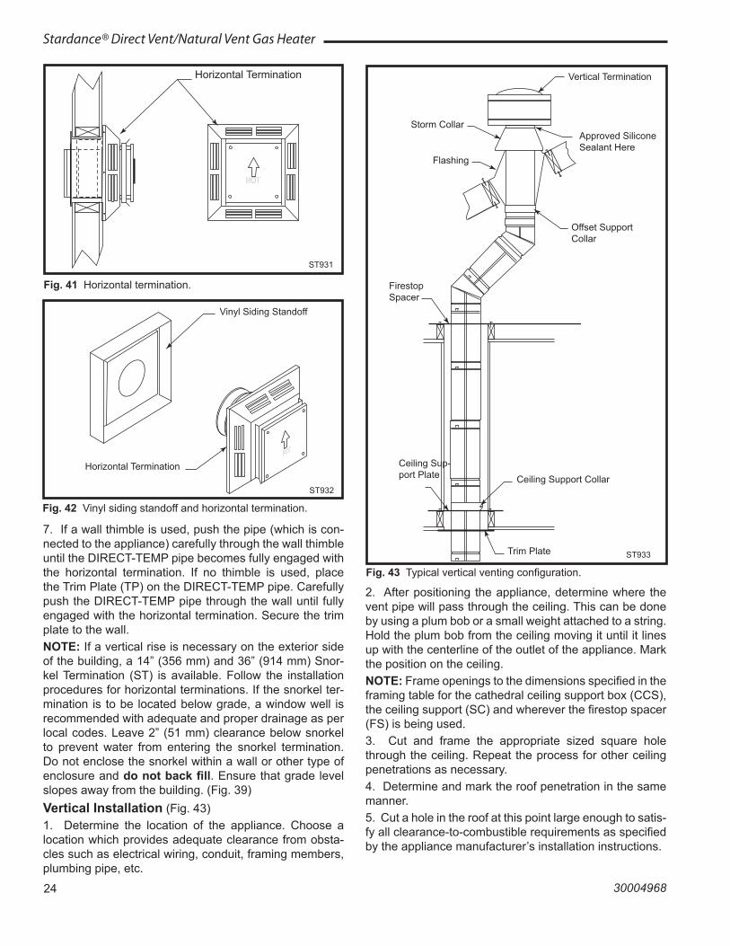
NOTE: The wall thimble accommodates wall thickness-es of 4Z\x” (114 mm) to 7Z\x” (191 mm). If a larger range is needed due to a thicker wall, it is permissible to field fabricate a metal sleeve extension and attach it to the shields.6. Install the horizontal termination to the exterior wall using four (4) all purpose screws through the holes lo-cated at each corner of the termination. Make sure the ar-row (embossed on the front of the termination) is pointing up. (Fig. 41) If the house has vinyl siding, a Vinyl Siding Standoff (VS) must be installed prior to installing the hori-zontal termination. Refer to the appliance manufacturer to determine if one is recommended. Attach the vinyl sid-ing standoff to the exterior side of the wall (making sure it is level and centered with respect to the opening) with screws (provided) at each corner of the standoff. Attach the horizontal termination to the standoff. (Fig. 42)If the wall is brick or concrete, and contains no combus-tible material, a 7” (178 mm) round penetration hole is ad-equate. The wall thimble is not required. The perforated straps of the horizontal termination provide a method of attachment. These can either be threaded through the opening or wall thimble (if used) and screwed to the pipe or removed with a pair of tin snips if not used. Use proper masonry fasteners to attach the horizontal termination to the wall.
24
Stardance® Direct Vent/Natural Vent Gas Heater
30004968
Horizontal Termination
ST931
Fig. 41 Horizontal termination.
ST932Selkirk standoff6/07
Vinyl Siding Standoff
ST932
Horizontal Termination
Fig. 42 Vinyl siding standoff and horizontal termination.
7. If a wall thimble is used, push the pipe (which is con-nected to the appliance) carefully through the wall thimble until the DIRECT-TEMP pipe becomes fully engaged with the horizontal termination. If no thimble is used, place the Trim Plate (TP) on the DIRECT-TEMP pipe. Carefully push the DIRECT-TEMP pipe through the wall until fully engaged with the horizontal termination. Secure the trim plate to the wall.NOTE: If a vertical rise is necessary on the exterior side of the building, a 14” (356 mm) and 36” (914 mm) Snor-kel Termination (ST) is available. Follow the installation procedures for horizontal terminations. If the snorkel ter-mination is to be located below grade, a window well is recommended with adequate and proper drainage as per local codes. Leave 2” (51 mm) clearance below snorkel to prevent water from entering the snorkel termination. Do not enclose the snorkel within a wall or other type of enclosure and do not back fill. Ensure that grade level slopes away from the building. (Fig. 39)Vertical Installation (Fig. 43)1. Determine the location of the appliance. Choose a location which provides adequate clearance from obsta-cles such as electrical wiring, conduit, framing members, plumbing pipe, etc.
Vertical Termination
Approved Silicone Sealant Here
Storm Collar
Flashing
Offset Support Collar
Firestop Spacer
Ceiling Support Collar
Ceiling Sup-port Plate
Trim Plate ST933
Fig. 43 Typical vertical venting configuration.
2. After positioning the appliance, determine where the vent pipe will pass through the ceiling. This can be done by using a plum bob or a small weight attached to a string. Hold the plum bob from the ceiling moving it until it lines up with the centerline of the outlet of the appliance. Mark the position on the ceiling.NOTE: Frame openings to the dimensions specified in the framing table for the cathedral ceiling support box (CCS), the ceiling support (SC) and wherever the firestop spacer (FS) is being used.3. Cut and frame the appropriate sized square hole through the ceiling. Repeat the process for other ceiling penetrations as necessary.4. Determine and mark the roof penetration in the same manner.5. Cut a hole in the roof at this point large enough to satis-fy all clearance-to-combustible requirements as specified by the appliance manufacturer’s installation instructions.
25
Stardance® Direct Vent/Natural Vent Gas Heater
30004968
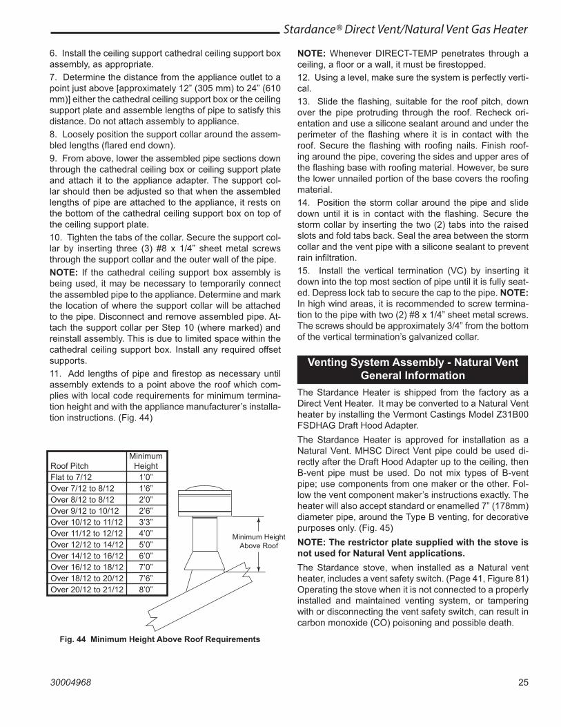
6. Install the ceiling support cathedral ceiling support box assembly, as appropriate.7. Determine the distance from the appliance outlet to a point just above [approximately 12” (305 mm) to 24” (610 mm)] either the cathedral ceiling support box or the ceiling support plate and assemble lengths of pipe to satisfy this distance. Do not attach assembly to appliance.8. Loosely position the support collar around the assem-bled lengths (flared end down).9. From above, lower the assembled pipe sections down through the cathedral ceiling box or ceiling support plate and attach it to the appliance adapter. The support col-lar should then be adjusted so that when the assembled lengths of pipe are attached to the appliance, it rests on the bottom of the cathedral ceiling support box on top of the ceiling support plate.10. Tighten the tabs of the collar. Secure the support col-lar by inserting three (3) #8 x 1/4” sheet metal screws through the support collar and the outer wall of the pipe.NOTE: If the cathedral ceiling support box assembly is being used, it may be necessary to temporarily connect the assembled pipe to the appliance. Determine and mark the location of where the support collar will be attached to the pipe. Disconnect and remove assembled pipe. At-tach the support collar per Step 10 (where marked) and reinstall assembly. This is due to limited space within the cathedral ceiling support box. Install any required offset supports.11. Add lengths of pipe and firestop as necessary until assembly extends to a point above the roof which com-plies with local code requirements for minimum termina-tion height and with the appliance manufacturer’s installa-tion instructions. (Fig. 44)
NOTE: Whenever DIRECT-TEMP penetrates through a ceiling, a floor or a wall, it must be firestopped.12. Using a level, make sure the system is perfectly verti-cal.13. Slide the flashing, suitable for the roof pitch, down over the pipe protruding through the roof. Recheck ori-entation and use a silicone sealant around and under the perimeter of the flashing where it is in contact with the roof. Secure the flashing with roofing nails. Finish roof-ing around the pipe, covering the sides and upper ares of the flashing base with roofing material. However, be sure the lower unnailed portion of the base covers the roofing material.14. Position the storm collar around the pipe and slide down until it is in contact with the flashing. Secure the storm collar by inserting the two (2) tabs into the raised slots and fold tabs back. Seal the area between the storm collar and the vent pipe with a silicone sealant to prevent rain infiltration.15. Install the vertical termination (VC) by inserting it down into the top most section of pipe until it is fully seat-ed. Depress lock tab to secure the cap to the pipe. NOTE: In high wind areas, it is recommended to screw termina-tion to the pipe with two (2) #8 x 1/4” sheet metal screws. The screws should be approximately 3/4” from the bottom of the vertical termination’s galvanized collar.
Minimum HeightAbove Roof
ST934minimum height6/07
Minimum Roof Pitch Height Flat to 7/12 1’0” Over 7/12 to 8/12 1’6” Over 8/12 to 8/12 2’0” Over 9/12 to 10/12 2’6” Over 10/12 to 11/12 3’3” Over 11/12 to 12/12 4’0” Over 12/12 to 14/12 5’0” Over 14/12 to 16/12 6’0” Over 16/12 to 18/12 7’0” Over 18/12 to 20/12 7’6” Over 20/12 to 21/12 8’0”
Fig. 44 Minimum Height Above Roof Requirements
Venting System Assembly - Natural VentGeneral Information
The Stardance Heater is shipped from the factory as a Direct Vent Heater. It may be converted to a Natural Vent heater by installing the Vermont Castings Model Z31B00 FSDHAG Draft Hood Adapter.The Stardance Heater is approved for installation as a Natural Vent. MHSC Direct Vent pipe could be used di-rectly after the Draft Hood Adapter up to the ceiling, then B-vent pipe must be used. Do not mix types of B-vent pipe; use components from one maker or the other. Fol-low the vent component maker’s instructions exactly. The heater will also accept standard or enamelled 7” (178mm) diameter pipe, around the Type B venting, for decorative purposes only. (Fig. 45)NOTE: The restrictor plate supplied with the stove is not used for Natural Vent applications.The Stardance stove, when installed as a Natural vent heater, includes a vent safety switch. (Page 41, Figure 81) Operating the stove when it is not connected to a properly installed and maintained venting system, or tampering with or disconnecting the vent safety switch, can result in carbon monoxide (CO) poisoning and possible death.
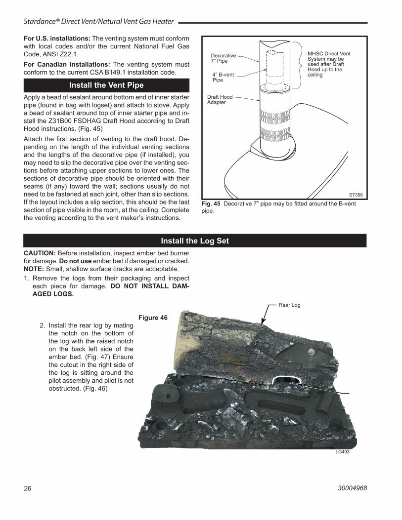
26
Stardance® Direct Vent/Natural Vent Gas Heater
30004968
For U.S. installations: The venting system must conform with local codes and/or the current National Fuel Gas Code, ANSI Z22.1.For Canadian installations: The venting system must conform to the current CSA B149.1 installation code.
Install the Vent PipeApply a bead of sealant around bottom end of inner starter pipe (found in bag with logset) and attach to stove. Apply a bead of sealant around top of inner starter pipe and in-stall the Z31B00 FSDHAG Draft Hood according to Draft Hood instructions. (Fig. 45)Attach the first section of venting to the draft hood. De-pending on the length of the individual venting sections and the lengths of the decorative pipe (if installed), you may need to slip the decorative pipe over the venting sec-tions before attaching upper sections to lower ones. The sections of decorative pipe should be oriented with their seams (if any) toward the wall; sections usually do not need to be fastened at each joint, other than slip sections. If the layout includes a slip section, this should be the last section of pipe visible in the room, at the ceiling. Complete the venting according to the vent maker’s instructions.
ST358 �Decorative �pipe around b-vent �4/26/00 djt
MHSC Direct Vent System may be used after Draft Hood up to the ceiling
Decorative 7” Pipe
4” B-vent Pipe
Draft Hood Adapter
ST358
Fig. 45 Decorative 7” pipe may be fitted around the B-vent pipe.
Install the Log Set
Rear Log
LG493
Figure 46
CAUTION: Before installation, inspect ember bed burner for damage. Do not use ember bed if damaged or cracked. NOTE: Small, shallow surface cracks are acceptable.1. Remove the logs from their packaging and inspect
each piece for damage. DO NOT INSTALL DAM-AGED LOGS.
2. Install the rear log by mating the notch on the bottom of the log with the raised notch on the back left side of the ember bed. (Fig. 47) Ensure the cutout in the right side of the log is sitting around the pilot assembly and pilot is not obstructed. (Fig. 46)
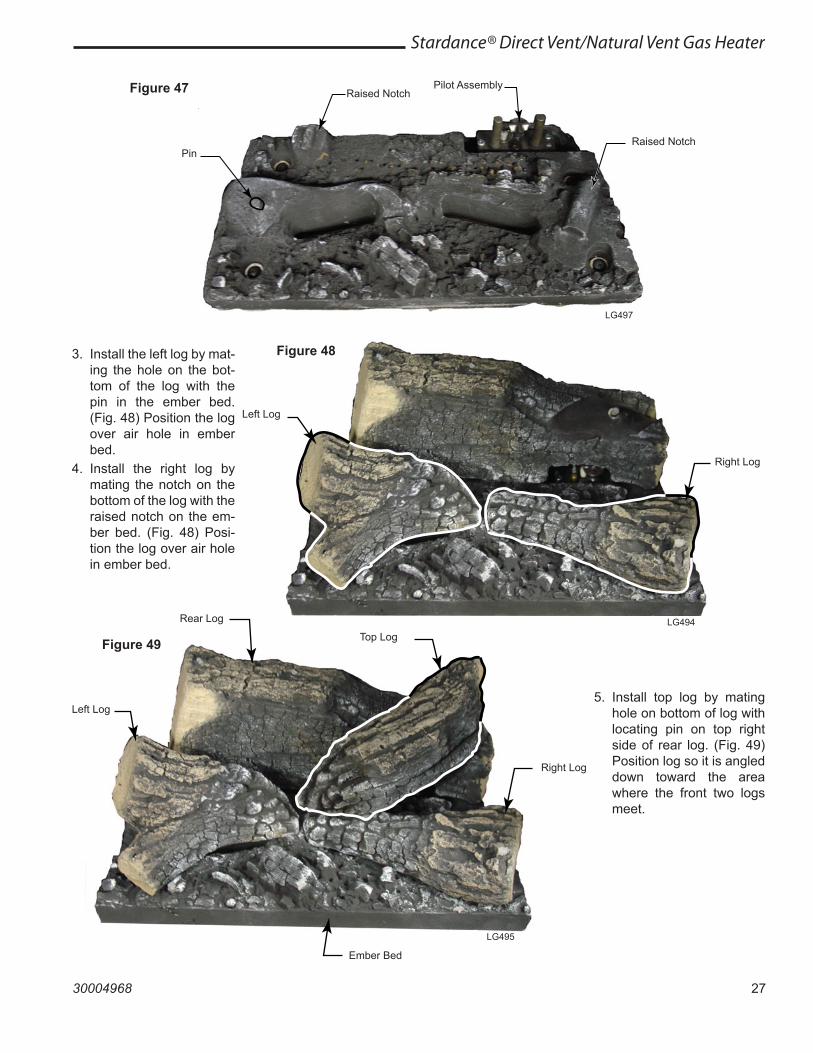
27
Stardance® Direct Vent/Natural Vent Gas Heater
30004968
Left Log
Right Log
Figure 48
LG494Rear Log
Top Log
Left Log
Right Log
Ember Bed
LG495
Figure 49
3. Install the left log by mat-ing the hole on the bot-tom of the log with the pin in the ember bed. (Fig. 48) Position the log over air hole in ember bed.
4. Install the right log by mating the notch on the bottom of the log with the raised notch on the em-ber bed. (Fig. 48) Posi-tion the log over air hole in ember bed.
Raised Notch
Pin
Pilot Assembly
Raised Notch
LG497
Figure 47
5. Install top log by mating hole on bottom of log with locating pin on top right side of rear log. (Fig. 49) Position log so it is angled down toward the area where the front two logs meet.
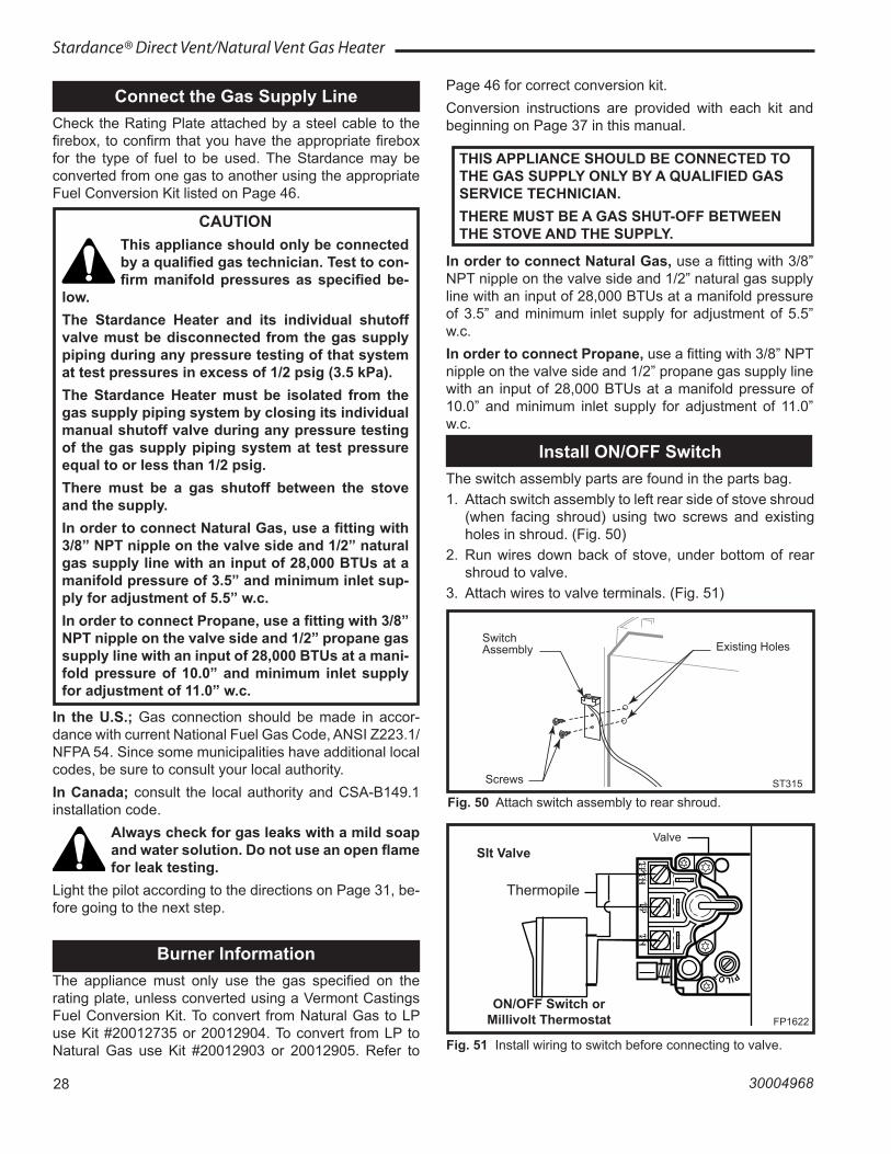
28
Stardance® Direct Vent/Natural Vent Gas Heater
30004968
Connect the Gas Supply LineCheck the Rating Plate attached by a steel cable to the firebox, to confirm that you have the appropriate firebox for the type of fuel to be used. The Stardance may be converted from one gas to another using the appropriate Fuel Conversion Kit listed on Page 46.
CAUTIONThis appliance should only be connected by a qualified gas technician. Test to con-firm manifold pressures as specified be-
low.The Stardance Heater and its individual shutoff valve must be disconnected from the gas supply piping during any pressure testing of that system at test pressures in excess of 1/2 psig (3.5 kPa).The Stardance Heater must be isolated from the gas supply piping system by closing its individual manual shutoff valve during any pressure testing of the gas supply piping system at test pressure equal to or less than 1/2 psig.There must be a gas shutoff between the stove and the supply.In order to connect Natural Gas, use a fitting with 3/8” NPT nipple on the valve side and 1/2” natural gas supply line with an input of 28,000 BTUs at a manifold pressure of 3.5” and minimum inlet sup-ply for adjustment of 5.5” w.c. In order to connect Propane, use a fitting with 3/8” NPT nipple on the valve side and 1/2” propane gas supply line with an input of 28,000 BTUs at a mani-fold pressure of 10.0” and minimum inlet supply for adjustment of 11.0” w.c.
In the U.S.; Gas connection should be made in accor-dance with current National Fuel Gas Code, ANSI Z223.1/NFPA 54. Since some municipalities have additional local codes, be sure to consult your local authority.In Canada; consult the local authority and CSA-B149.1 installation code.
Always check for gas leaks with a mild soap and water solution. Do not use an open flame for leak testing.
Light the pilot according to the directions on Page 31, be-fore going to the next step.
Burner InformationThe appliance must only use the gas specified on the rating plate, unless converted using a Vermont Castings Fuel Conversion Kit. To convert from Natural Gas to LP use Kit #20012735 or 20012904. To convert from LP to Natural Gas use Kit #20012903 or 20012905. Refer to
Page 46 for correct conversion kit.Conversion instructions are provided with each kit and beginning on Page 37 in this manual.
THIS APPLIANCE SHOULD BE CONNECTED TO THE GAS SUPPLY ONLY BY A QUALIFIED GAS SERVICE TECHNICIAN.THERE MUST BE A GAS SHUT-OFF BETWEEN THE STOVE AND THE SUPPLY.
In order to connect Natural Gas, use a fitting with 3/8” NPT nipple on the valve side and 1/2” natural gas supply line with an input of 28,000 BTUs at a manifold pressure of 3.5” and minimum inlet supply for adjustment of 5.5” w.c.In order to connect Propane, use a fitting with 3/8” NPT nipple on the valve side and 1/2” propane gas supply line with an input of 28,000 BTUs at a manifold pressure of 10.0” and minimum inlet supply for adjustment of 11.0” w.c.
Install ON/OFF SwitchThe switch assembly parts are found in the parts bag.1. Attach switch assembly to left rear side of stove shroud
(when facing shroud) using two screws and existing holes in shroud. (Fig. 50)
2. Run wires down back of stove, under bottom of rear shroud to valve.
3. Attach wires to valve terminals. (Fig. 51)
ST315 �attach switch assy �1/31/00 djt
Switch Assembly Existing Holes
Screws ST315
Fig. 50 Attach switch assembly to rear shroud.
PILOT
TPT
HT
P T
H
FP1622SIT valve w/switch
FP1622
Fig. 51 Install wiring to switch before connecting to valve.
SIt ValveValve
Thermopile
ON/OFF Switch or Millivolt Thermostat
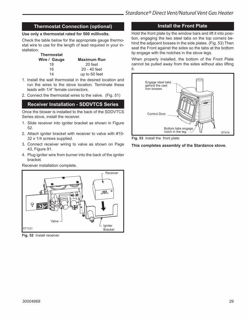
29
Stardance® Direct Vent/Natural Vent Gas Heater
30004968
Thermostat Connection (optional)Use only a thermostat rated for 500 millivolts.Check the table below for the appropriate gauge thermo-stat wire to use for the length of lead required in your in-stallation. Thermostat Wire / Gauge Maximum Run 18 20 feet 16 20 - 40 feet 14 up to 60 feet1. Install the wall thermostat in the desired location and
run the wires to the stove location. Terminate these leads with 1/4” female connectors.
2. Connect the thermostat wires to the valve. (Fig. 51)
Install the Front PlateHold the front plate by the window bars and lift it into posi-tion, engaging the two steel tabs on the top corners be-hind the adjacent bosses in the side plates. (Fig. 53) Then seat the Front against the sides so the tabs at the bottom lip engage with the notches in the stove legs. When properly installed, the bottom of the Front Plate cannot be pulled away from the sides without also lifting it.
ST474StardanceFront10/3/00
Engage steel tabs gehind the cast iron bosses
Control Door
Bottom tabs engage notch in the leg. ST474
Fig. 53 Install the front plate.
This completes assembly of the Stardance stove.
Receiver Installation - SDDVTCS SeriesOnce the blower is installed to the back of the SDDVTCS Series stove, install the receiver.1. Slide receiver into igniter bracket as shown in Figure
52. 2. Attach igniter bracket with receiver to valve with #10-
32 x 1/4 screws supplied.3. Connect receiver wiring to valve as shown on Page
43, Figure 91.4. Plug igniter wire from burner into the back of the igniter
bracket.Receiver installation complete.
ST1121receiver install
Receiver
Igniter Bracket
Valve
ST1121
Fig. 52 Install receiver.
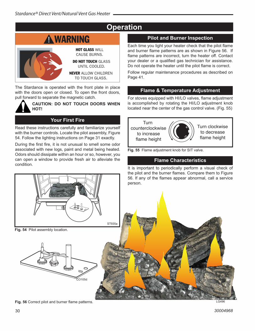
30
Stardance® Direct Vent/Natural Vent Gas Heater
30004968
The Stardance is operated with the front plate in place with the doors open or closed. To open the front doors, pull forward to separate the magnetic catch.
CAUTION: DO NOT TOUCH DOORS WHEN HOT!
Your First FireRead these instructions carefully and familiarize yourself with the burner controls. Locate the pilot assembly, Figure 54. Follow the lighting instructions on Page 31 exactly. During the first fire, it is not unusual to smell some odor associated with new logs, paint and metal being heated. Odors should dissipate within an hour or so, however, you can open a window to provide fresh air to alleviate the condition.
Flame & Temperature AdjustmentFor stoves equipped with HI/LO valves, flame adjustment is accomplished by rotating the HI/LO adjustment knob located near the center of the gas control valve. (Fig. 55)
Fig. 55 Flame adjustment knob for SIT valve.
LO
HI
FP390FLAME ADJUSTMENT KNOB11/21/96
Turn counterclockwise
to increaseflame height
Turn clockwiseto decreaseflame height
Flame CharacteristicsIt is important to periodically perform a visual check of the pilot and the burner flames. Compare them to Figure 56. If any of the flames appear abnormal, call a service person.
CO105d
Fig. 56 Correct pilot and burner flame patterns. LG496
Operation
ST935SDDVTpilot location6/07
ST935a
Fig. 54 Pilot assembly location.
Pilot and Burner InspectionEach time you light your heater check that the pilot flame and burner flame patterns are as shown in Figure 56. If flame patterns are incorrect, turn the heater off. Contact your dealer or a qualified gas technician for assistance. Do not operate the heater until the pilot flame is correct.Follow regular maintenance procedures as described on Page 41.
CO105dPilot flame6/07 djt
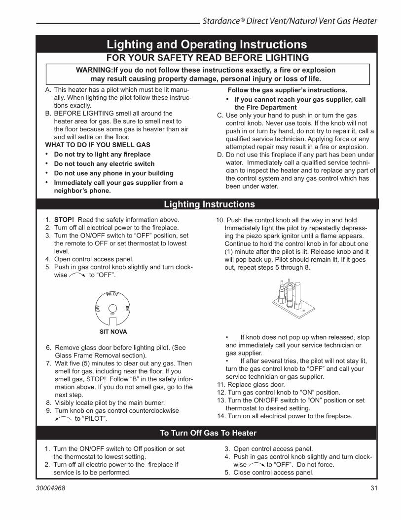
31
Stardance® Direct Vent/Natural Vent Gas Heater
30004968
3. Open control access panel.4. Push in gas control knob slightly and turn clock-
wise to “OFF”. Do not force.5. Close control access panel.
1. STOP! Read the safety information above.2. Turn off all electrical power to the fireplace.3. Turn the ON/OFF switch to “OFF” position, set
the remote to OFF or set thermostat to lowest level.
4. Open control access panel.5. Push in gas control knob slightly and turn clock-
wise to “OFF”.
10. Push the control knob all the way in and hold. Immediately light the pilot by repeatedly depress-ing the piezo spark ignitor until a flame appears. Continue to hold the control knob in for about one (1) minute after the pilot is lit. Release knob and it will pop back up. Pilot should remain lit. If it goes out, repeat steps 5 through 8.
FOR YOUR SAFETY READ BEFORE LIGHTING
Follow the gas supplier’s instructions.• If you cannot reach your gas supplier, call
the Fire DepartmentC. Use only your hand to push in or turn the gas
control knob. Never use tools. If the knob will not push in or turn by hand, do not try to repair it, call a qualified service technician. Applying force or any attempted repair may result in a fire or explosion.
D. Do not use this fireplace if any part has been under water. Immediately call a qualified service techni-cian to inspect the heater and to replace any part of the control system and any gas control which has been under water.
A. This heater has a pilot which must be lit manu-ally. When lighting the pilot follow these instruc-tions exactly.
B. BEFORE LIGHTING smell all around the heater area for gas. Be sure to smell next to the floor because some gas is heavier than air and will settle on the floor.
WHAT TO DO IF YOU SMELL GAS• Do not try to light any fireplace• Do not touch any electric switch• Do not use any phone in your building• Immediately call your gas supplier from a
neighbor’s phone.
To Turn Off Gas To Heater
Lighting and Operating Instructions
1. Turn the ON/OFF switch to Off position or set the thermostat to lowest setting.
2. Turn off all electric power to the fireplace if service is to be performed.
Lighting Instructions
6. Remove glass door before lighting pilot. (See Glass Frame Removal section).
7. Wait five (5) minutes to clear out any gas. Then smell for gas, including near the floor. If you smell gas, STOP! Follow “B” in the safety infor-mation above. If you do not smell gas, go to the next step.
8. Visibly locate pilot by the main burner.9. Turn knob on gas control counterclockwise
to “PILOT”.
• If knob does not pop up when released, stop and immediately call your service technician or gas supplier.
• If after several tries, the pilot will not stay lit, turn the gas control knob to “OFF” and call your service technician or gas supplier.
11. Replace glass door.12. Turn gas control knob to “ON” position.13. Turn the ON/OFF switch to “ON” position or set
thermostat to desired setting.14. Turn on all electrical power to the fireplace.
WARNING:If you do not follow these instructions exactly, a fire or explosion may result causing property damage, personal injury or loss of life.
SIT NOVA
PILOT
ON
OFF
ON
PILOT
OFF
OFF
FP1067lighting instructionknobs3/9/01 djt
5 4 3
21
OFF
Pilot
3/8" - 1/2"
FP1068Lighting instructionsPilots
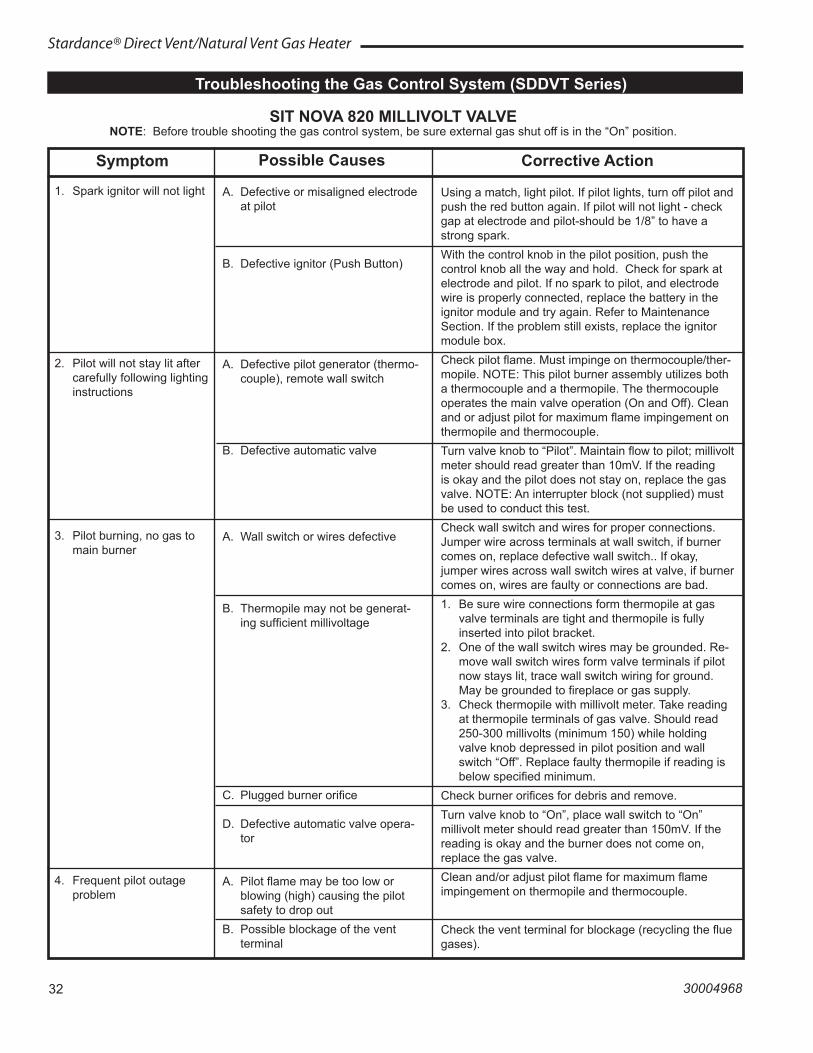
32
Stardance® Direct Vent/Natural Vent Gas Heater
30004968
Troubleshooting the Gas Control System (SDDVT Series)
NOTE: Before trouble shooting the gas control system, be sure external gas shut off is in the “On” position.SIT NOVA 820 MILLIVOLT VALVE
Symptom
1. Spark ignitor will not light
2. Pilot will not stay lit after carefully following lighting instructions
3. Pilot burning, no gas to main burner
4. Frequent pilot outage problem
Possible Causes
A. Defective or misaligned electrode at pilot
B. Defective ignitor (Push Button)
A. Defective pilot generator (thermo-couple), remote wall switch
B. Defective automatic valve
A. Wall switch or wires defective
B. Thermopile may not be generat-ing sufficient millivoltage
C. Plugged burner orifice
D. Defective automatic valve opera-tor
A. Pilot flame may be too low or blowing (high) causing the pilot safety to drop out
B. Possible blockage of the vent terminal
Corrective Action
Using a match, light pilot. If pilot lights, turn off pilot and push the red button again. If pilot will not light - check gap at electrode and pilot-should be 1/8” to have a strong spark.With the control knob in the pilot position, push the control knob all the way and hold. Check for spark at electrode and pilot. If no spark to pilot, and electrode wire is properly connected, replace the battery in the ignitor module and try again. Refer to Maintenance Section. If the problem still exists, replace the ignitor module box.Check pilot flame. Must impinge on thermocouple/ther-mopile. NOTE: This pilot burner assembly utilizes both a thermocouple and a thermopile. The thermocouple operates the main valve operation (On and Off). Clean and or adjust pilot for maximum flame impingement on thermopile and thermocouple.Turn valve knob to “Pilot”. Maintain flow to pilot; millivolt meter should read greater than 10mV. If the reading is okay and the pilot does not stay on, replace the gas valve. NOTE: An interrupter block (not supplied) must be used to conduct this test.Check wall switch and wires for proper connections. Jumper wire across terminals at wall switch, if burner comes on, replace defective wall switch.. If okay, jumper wires across wall switch wires at valve, if burner comes on, wires are faulty or connections are bad.1. Be sure wire connections form thermopile at gas
valve terminals are tight and thermopile is fully inserted into pilot bracket.
2. One of the wall switch wires may be grounded. Re-move wall switch wires form valve terminals if pilot now stays lit, trace wall switch wiring for ground. May be grounded to fireplace or gas supply.
3. Check thermopile with millivolt meter. Take reading at thermopile terminals of gas valve. Should read 250-300 millivolts (minimum 150) while holding valve knob depressed in pilot position and wall switch “Off”. Replace faulty thermopile if reading is below specified minimum.
Check burner orifices for debris and remove.Turn valve knob to “On”, place wall switch to “On” millivolt meter should read greater than 150mV. If the reading is okay and the burner does not come on, replace the gas valve.Clean and/or adjust pilot flame for maximum flame impingement on thermopile and thermocouple.
Check the vent terminal for blockage (recycling the flue gases).
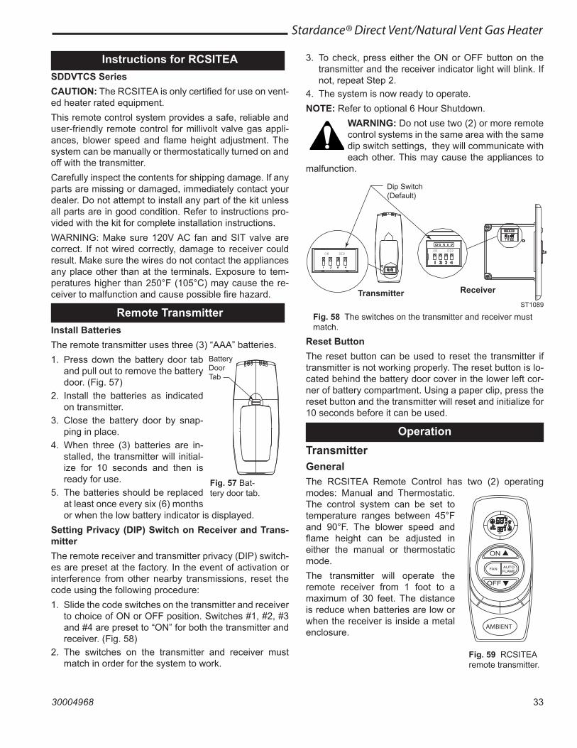
33
Stardance® Direct Vent/Natural Vent Gas Heater
30004968
Instructions for RCSITEASDDVTCS SeriesCAUTION: The RCSITEA is only certified for use on vent-ed heater rated equipment.This remote control system provides a safe, reliable and user-friendly remote control for millivolt valve gas appli-ances, blower speed and flame height adjustment. The system can be manually or thermostatically turned on and off with the transmitter. Carefully inspect the contents for shipping damage. If any parts are missing or damaged, immediately contact your dealer. Do not attempt to install any part of the kit unless all parts are in good condition. Refer to instructions pro-vided with the kit for complete installation instructions.WARNING: Make sure 120V AC fan and SIT valve are correct. If not wired correctly, damage to receiver could result. Make sure the wires do not contact the appliances any place other than at the terminals. Exposure to tem-peratures higher than 250°F (105°C) may cause the re-ceiver to malfunction and cause possible fire hazard.
Remote TransmitterInstall BatteriesThe remote transmitter uses three (3) “AAA” batteries.1. Press down the battery door tab
and pull out to remove the battery door. (Fig. 57)
2. Install the batteries as indicated on transmitter.
3. Close the battery door by snap-ping in place.
4. When three (3) batteries are in-stalled, the transmitter will initial-ize for 10 seconds and then is ready for use.
5. The batteries should be replaced at least once every six (6) months or when the low battery indicator is displayed.
Setting Privacy (DIP) Switch on Receiver and Trans-mitterThe remote receiver and transmitter privacy (DIP) switch-es are preset at the factory. In the event of activation or interference from other nearby transmissions, reset the code using the following procedure:1. Slide the code switches on the transmitter and receiver
to choice of ON or OFF position. Switches #1, #2, #3 and #4 are preset to “ON” for both the transmitter and receiver. (Fig. 58)
2. The switches on the transmitter and receiver must match in order for the system to work.
ST1088RCSITE battery tab
Battery Door Tab
Fig. 57 Bat-tery door tab.
3. To check, press either the ON or OFF button on the transmitter and the receiver indicator light will blink. If not, repeat Step 2.
4. The system is now ready to operate.NOTE: Refer to optional 6 Hour Shutdown.
WARNING: Do not use two (2) or more remote control systems in the same area with the same dip switch settings, they will communicate with each other. This may cause the appliances to
malfunction.
Reset ButtonThe reset button can be used to reset the transmitter if transmitter is not working properly. The reset button is lo-cated behind the battery door cover in the lower left cor-ner of battery compartment. Using a paper clip, press the reset button and the transmitter will reset and initialize for 10 seconds before it can be used.
OperationTransmitterGeneralThe RCSITEA Remote Control has two (2) operating modes: Manual and Thermostatic. The control system can be set to temperature ranges between 45°F and 90°F. The blower speed and flame height can be adjusted in either the manual or thermostatic mode.The transmitter will operate the remote receiver from 1 foot to a maximum of 30 feet. The distance is reduce when batteries are low or when the receiver is inside a metal enclosure.
ON DIPON DIP
ST1089RCSITE dip switches
Fig. 58 The switches on the transmitter and receiver must match.
Transmitter Receiver
Dip Switch (Default)
ST1089
Fig. 59 RCSITEA remote transmitter.
FAN AUTO
AMBIENT
ST1090RCSITE remote
ON
FLAME
OFF
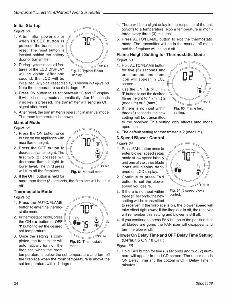
34
Stardance® Direct Vent/Natural Vent Gas Heater
30004968
Initial StartupFigure 601. After initial power up or
when RESET button is pressed, the transmitter is reset. The reset button is located behind the battery door of transmitter.
2. During system reset, all fea-tures of the LCD DISPLAY will be visible. After one second, the LCD will be initialized. A typical reset display is shown in Figure 60. Note the temperature scale is degree F.
3. Press ON button to select between °C and °F display. It will exit setting mode automatically after 10 seconds if no key is pressed. The transmitter will send an OFF signal after reset.
4. After reset, the transmitter is operating in manual mode. The room temperature is shown.
Manual ModeFigure 611. Press the ON button once
to turn on the appliance with max flame height.
2. Press the OFF button to decrease flame height. The first two (2) presses will decrease flame height to lower level. The third press will turn off the fireplace.
3. If the OFF button is held for more than three (3) seconds, the fireplace will be shut off.
Thermostatic Mode Figure 621. Press the AUTO/FLAME
button to enter the thermo-static mode.
2. In thermostatic mode, press the ON / ▲ button or OFF / ▼ button to set the desired set temperature.
3. Once the setting is com-pleted, the transmitter will automatically turn on the fireplace when the room temperature is below the set temperature and turn off the fireplace when the room temperature is above the set temperature within 1 degree.
°F
FP2142initial start up
Fig. 60 Typical Reset Display
FP2142
FP2143
°F
FP2143manual mode12/08
Fig. 61 Manual mode.
FP2144thermostat mode12/08
°F
°F
SET
Fig. 62 Thermostatic mode.
FP2144
4. There will be a slight delay in the response of the unit (on/off) to a temperature. Room temperature is moni-tored every three (3) minutes.
5. Press AUTO/FLAME button to exit the thermostatic mode. The transmitter will be in the manual off mode and the fireplace will be shut off.
Flame Height Setting for Thermostatic Mode Figure 631. Hold AUTO/FLAME button
for five (5) seconds and one number and flame icon will appear in LCD screen.
2. Use the ON / ▲ or OFF / ▼ button to set the desired flame height to 1 (min.) 2 (medium) or 3 (max.).
3. If there is no input within three (3) seconds, the new setting will be transmitted to the receiver. This setting only affects auto mode operation.
4. The default setting for transmitter is 2 (medium). 3-Speed Blower Control Figure 641. Press FAN button once to
enter blower speed setup mode at low speed initially and one of the three blade icons will display dark-ened on LCD display.
2. Continue to press FAN button to set the blower speed you desire.
3. If there is no input within three (3) seconds, the new setting will be transmitted to receiver. If the fireplace is on, the blower speed will take effect right away; if the fireplace is off, the receiver will remember this setting and blower is still off.
4. If you continue to press FAN button to the position that all blades are gone, the FAN icon will disappear and turn the blower off.
Blower On Delay Time and OFF Delay Time Setting (Default 5 ON / 8 OFF)
Figure 651. Hold FAN button for five (5) seconds and two (2) num-
bers will appear in the LCD screen. The upper one is ON Delay Time and the bottom is OFF Delay Time in minutes.
FP2147flame height setting12/08
Fig. 63 Flame height setting.
FP2147
FP2145
°F
FP21453 speed fan12/08
Fig. 64 3 speed blower control.
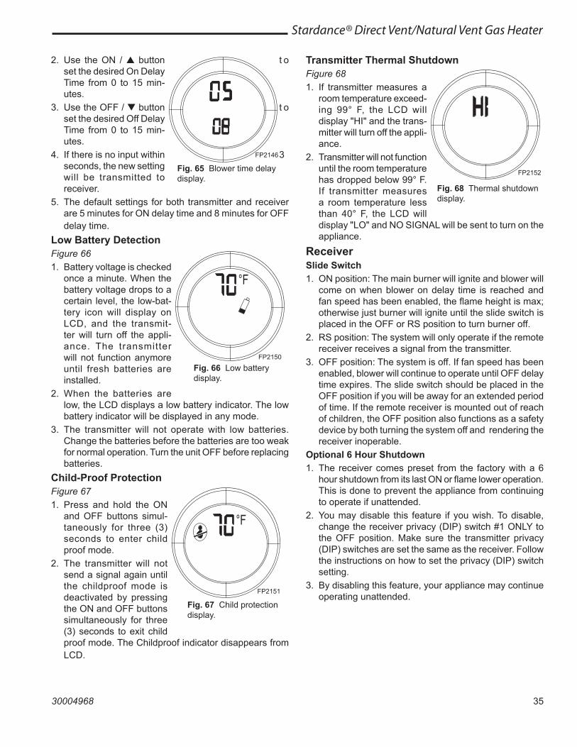
35
Stardance® Direct Vent/Natural Vent Gas Heater
30004968
Transmitter Thermal ShutdownFigure 681. If transmitter measures a
room temperature exceed-ing 99° F, the LCD will display "HI" and the trans-mitter will turn off the appli-ance.
2. Transmitter will not function until the room temperature has dropped below 99° F. If transmitter measures a room temperature less than 40° F, the LCD will display "LO" and NO SIGNAL will be sent to turn on the appliance.
ReceiverSlide Switch1. ON position: The main burner will ignite and blower will
come on when blower on delay time is reached and fan speed has been enabled, the flame height is max; otherwise just burner will ignite until the slide switch is placed in the OFF or RS position to turn burner off.
2. RS position: The system will only operate if the remote receiver receives a signal from the transmitter.
3. OFF position: The system is off. If fan speed has been enabled, blower will continue to operate until OFF delay time expires. The slide switch should be placed in the OFF position if you will be away for an extended period of time. If the remote receiver is mounted out of reach of children, the OFF position also functions as a safety device by both turning the system off and rendering the receiver inoperable.
Optional 6 Hour Shutdown1. The receiver comes preset from the factory with a 6
hour shutdown from its last ON or flame lower operation. This is done to prevent the appliance from continuing to operate if unattended.
2. You may disable this feature if you wish. To disable, change the receiver privacy (DIP) switch #1 ONLY to the OFF position. Make sure the transmitter privacy (DIP) switches are set the same as the receiver. Follow the instructions on how to set the privacy (DIP) switch setting.
3. By disabling this feature, your appliance may continue operating unattended.
2. Use the ON / ▲ button t o set the desired On Delay Time from 0 to 15 min-utes.
3. Use the OFF / ▼ button t o set the desired Off Delay Time from 0 to 15 min-utes.
4. If there is no input within 3 seconds, the new setting will be transmitted to receiver.
5. The default settings for both transmitter and receiver are 5 minutes for ON delay time and 8 minutes for OFF delay time.
Low Battery DetectionFigure 661. Battery voltage is checked
once a minute. When the battery voltage drops to a certain level, the low-bat-tery icon will display on LCD, and the transmit-ter will turn off the appli-ance. The transmitter will not function anymore until fresh batteries are installed.
2. When the batteries are low, the LCD displays a low battery indicator. The low battery indicator will be displayed in any mode.
3. The transmitter will not operate with low batteries. Change the batteries before the batteries are too weak for normal operation. Turn the unit OFF before replacing batteries.
Child-Proof ProtectionFigure 671. Press and hold the ON
and OFF buttons simul-taneously for three (3) seconds to enter child proof mode.
2. The transmitter will not send a signal again until the childproof mode is deactivated by pressing the ON and OFF buttons simultaneously for three (3) seconds to exit child proof mode. The Childproof indicator disappears from LCD.
FP2146
FP2146blower delay timer12/08
Fig. 65 Blower time delay display.
FP2150
°F
FP2150low battery display12/08
Fig. 66 Low battery display.
°F
FP2151no child display12/08
FP2151
Fig. 67 Child protection display.
FP2152thermal shutdown display12/08
FP2152
Fig. 68 Thermal shutdown display.
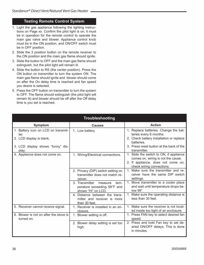
36
Stardance® Direct Vent/Natural Vent Gas Heater
30004968
Testing Remote Control System1. Light the gas appliance following the lighting instruc-
tions on Page xx. Confirm the pilot light is on; it must be in operation for the remote control to operate the main gas valve and blower. Appliance control knob must be in the ON position, and ON/OFF switch must be in OFF position.
2. Slide the 3 position button on the remote receiver to the ON position and the main gas flame should ignite.
3. Slide the button to OFF and the main gas flame should extinguish, but the pilot light will remain lit.
4. Slide the button to RS (the center position). Press the ON button on transmitter to turn the system ON. The main gas flame should ignite and blower should come on after the On delay time is reached and fan speed you desire is selected.
5. Press the OFF button on transmitter to turn the system to OFF. The flame should extinguish (the pilot light will remain lit) and blower should be off after the Off delay time is you set is reached.
Symptom1. Battery icon on LCD on transmit-
ter.2. LCD display is blank.
3. LCD display shows “funny” dis-play.
4. Appliance does not come on.
5. Receiver cannot receive signal.
6. Blower is not on after the stove is turned on.
Causes1. Low battery.
1. Wiring/Electrical connections.
2. Privacy (DIP) switch setting on transmitter does not match re-ceiver.
3. Transmitter measure tem-perature exceeding 99°F and shows “HI” on LCD.
4. Distance between the trans-mitter and receiver is more than 30 feet.
1. Receiver is installed in an en-closure.
1. Blower setting is off.
2. Blower delay setting is set too high.
Action1. Replace batteries. Change the bat-
teries every 6 months.2. Check battery installation or replace
batteries.3. Press reset button at the back of the
transmitter.1. Slide the switch to ON, if appliance
comes on, wiring is not the cause.2. If appliance, does not come on,
check wiring connections.1. Make sure the transmitter and re-
ceiver have the same DIP switch settings.
1. Move transmitter to a cooler place and wait until temperature drops be-low 99°.
1. Make sure the operating distance is less than 30 feet.
1. Make sure the receiver is not locat-ed inside too tight of an enclosure.
1. Press FAN key to select desired fan speed.
2. Press and hold Fan key to set de-sired ON/OFF delays. This is done in minutes.
Troubleshooting
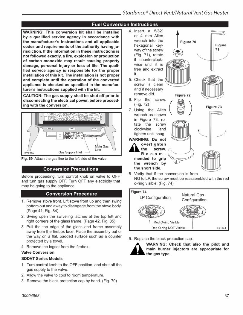
37
Stardance® Direct Vent/Natural Vent Gas Heater
30004968
Fuel Conversion InstructionsWARNING! This conversion kit shall be installed by a qualified service agency in accordance with the manufacturer’s instructions and all applicable codes and requirements of the authority having ju-risdiction. If the information in these instructions is not followed exactly, a fire, explosion or production of carbon monoxide may result causing property damage, personal injury or loss of life. The quali-fied service agency is responsible for the proper installation of this kit. The installation is not proper and complete until the operation of the converted appliance is checked as specified in the manufac-turer’s instructions supplied with the kit.CAUTION: The gas supply shall be shut off prior to disconnecting the electrical power, before proceed-ing with the conversion.
ST226battach gas line6/07 djt
Gas Supply Inlet
Main Gas Line
ST226a
Fig. 69 Attach the gas line to the left side of the valve.
Conversion PrecautionsBefore proceeding, turn control knob on valve to OFF and turn gas supply OFF. Turn OFF any electricity that may be going to the appliance.
Conversion Procedure1. Remove stove front. Lift stove front up and then swing
bottom out and away to disengage from the stove body. (Page 41, Fig. 84)
2. Swing open the swiveling latches at the top left and right corners of the glass frame. (Page 42, Fig. 85)
3. Pull the top edge of the glass and frame assembly away from the firebox face. Place the assembly out of the way on a flat, padded surface such as a counter protected by a towel.
4. Remove the logset from the firebox.Valve ConversionSDDVT Series Models1. Turn control knob to the OFF position, and shut off the
gas supply to the valve.2. Allow the valve to cool to room temperature.3. Remove the black protection cap by hand. (Fig. 70)
4. Insert a 5/32” or 4 mm Allen wrench into the hexagonal key-way of the screw (Fig. 71), rotate it counterclock-wise until it is free and extract it.
5. Check that the screw is clean and if necessary remove dirt.
6. Flip the screw. (Fig. 72)
7. Using the Allen wrench as shown in Figure 73, ro-tate the screw clockwise and tighten until snug.
WARNING: Do not overtighten the screw. R e c o m -
mended to grip the wrench by the short side.
8. Verify that if the conversion is from NG to LP, the screw must be reassembled with the red o-ring visible. (Fig. 74)
LP ConfigurationNatural GasConfiguration
CO141O-ring configuration6/07
Red O-ring Visible
Red O-ring NOT Visible CO141
Figure 74
Figure 70Figure 71
Figure 72
Figure 73
9. Replace the black protection cap.WARNING: Check that also the pilot and main burner injectors are appropriate for the gas type.
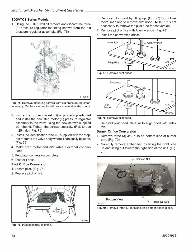
38
Stardance® Direct Vent/Natural Vent Gas Heater
30004968
SDDVTCS Series Models1. Using the TORX T20 bit remove and discard the three
(3) pressure regulator mounting screws from the old pressure regulator assembly. (Fig. 75)
ST935SDDVTpilot location6/07
ST935
Fig. 76 Pilot assembly location.
CO105a �gas conversion �Pilot �1/28/00 djt
�
Pilot Hood
Pilot Bracket
CO105a
Fig. 78 Remove pilot hood.
CO106a �DV360/580 �Gas Conversion �Pilot2 �1/28/00 djt
Index Tab
Snap Ring
CO106a
Fig. 77 Remove pilot orifice.
Allen Wrench
Remove Nuts
Remove Nut
Bottom View
Fig. 79 Remove three (3) nuts securing ember bed in place.ST918
2. Insure the rubber gasket (D) is properly positioned and install the new step motor (E) pressure regulator assembly to the valve using the new screws supplied with the kit. Tighten the screws securely. (Ref. torque = 25 in/lb) (Fig. 75)
3. Install the identification label (F) supplied with the step-per motor to the valve body where it can easily be seen. (Fig. 75)
4. Make step motor and mV valve electrical connec-tions.
5. Regulator conversion complete.6. Test for LeaksPilot Orifice Conversion1. Locate pilot. (Fig. 76)2. Replace pilot orifice.
ST1093install new step motor
ST1093
Fig. 75 Remove mounting screws from old pressure regulator assembly. Replace step motor with new conversion step motor.
3. Remove pilot hood by lifting up. (Fig. 77) Do not re-move snap ring to remove pilot hood. NOTE: It is not necessary to remove the pilot tube for conversion.
4. Remove pilot orifice with Allen wrench. (Fig. 78)5. Install the conversion orifice.
6. Reinstall pilot hood. Be sure to align hood with index tab.
Burner Orifice Conversion1. Remove three (3) 3/8” nuts on bottom side of burner
pan. (Fig. 79)2. Carefully remove ember bed by tilting the right side
up and lifting out toward the right side of the unit. (Fig. 79)
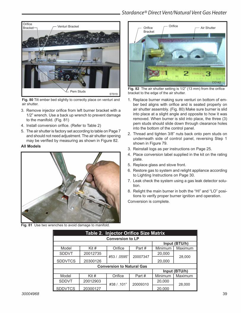
39
Stardance® Direct Vent/Natural Vent Gas Heater
30004968
Pem StudsST919
Fig. 80 Tilt ember bed slightly to correctly place on venturi and air shutter.
Orifice Bracket Venturi Bracket Orifice
Bracket
Orifice Air Shutter
CO142
Fig. 82 The air shutter setting is 1/2” (13 mm) from the orifice bracket to the edge of the air shutter.
3. Remove injector orifice from left burner bracket with a 1/2” wrench. Use a back up wrench to prevent damage to the manifold. (Fig. 81)
4. Install conversion orifice. (Refer to Table 2)5. The air shutter is factory set according to table on Page 7
and should not need adjustment. The air shutter opening may be verified by measuring as shown in Figure 82.
All Models
CO145
Fig. 81 Use two wrenches to avoid damage to manifold.
1. Replace burner making sure venturi on bottom of em-ber bed aligns with orifice and is seated properly on air shutter assembly. (Fig. 80) Make sure burner is slid into place at a slight angle and opposite to how it was removed. When burner is slid into place, the three (3) pem studs should slide down through clearance holes into the bottom of the control panel.
2. Thread and tighten 3/8” nuts back onto pem studs on underneath side of control panel, reversing Step 1 shown in Figure 79.
3. Reinstall logs as per instructions on Page 25. 4. Place conversion label supplied in the kit on the rating
plate.5. Replace glass and stove front.6. Restore gas to system and relight appliance according
to Lighting Instructions on Page 30. 7. Leak check the system using a gas leak detector solu-
tion.8. Relight the main burner in both the “HI” and “LO” posi-
tions to verify proper burner ignition and operation.Conversion is complete.
Conversion to Natural Gas Input (BTU/h) Model Kit # Orifice Part # Minimum Maximum SDDVT 20012903 20,000
SDDVTCS 20300127 #38 / .101” 20009310
20,000 28,000
Table 2. Injector Orifice Size Matrix Conversion to LP Input (BTU/h) Model Kit # Orifice Part # Minimum Maximum SDDVT 20012735 20,000
SDDVTCS 20300126 #53 / .0595” 20007347
20,000 28,000
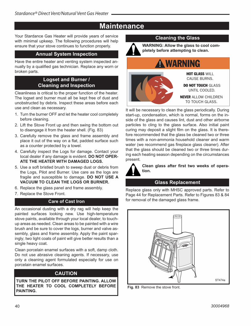
40
Stardance® Direct Vent/Natural Vent Gas Heater
30004968
MaintenanceYour Stardance Gas Heater will provide years of service with minimal upkeep. The following procedures will help ensure that your stove continues to function properly.
Annual System InspectionHave the entire heater and venting system inspected an-nually by a qualified gas technician. Replace any worn or broken parts.
Logset and Burner / Cleaning and Inspection
Cleanliness is critical to the proper function of the heater. The logset and burner must all be kept free of dust and unobstructed by debris. Inspect these areas before each use and clean as necessary.1. Turn the burner OFF and let the heater cool completely
before cleaning.2. Lift the Stove Front up and then swing the bottom out
to disengage it from the heater shell. (Fig. 83)3. Carefully remove the glass and frame assembly and
place it out of the way on a flat, padded surface such as a counter protected by a towel.
4. Carefully inspect the Logs for damage. Contact your local dealer if any damage is evident. DO NOT OPER-ATE THE HEATER WITH DAMAGED LOGS.
5. Use a soft bristled brush to sweep dust or debris from the Logs, Pilot and Burner. Use care as the logs are fragile and susceptible to damage. DO NOT USE A VACUUM TO CLEAN THE LOGS OR BURNER.
6. Replace the glass panel and frame assembly.7. Replace the Stove Front.
Care of Cast IronAn occasional dusting with a dry rag will help keep the painted surfaces looking new. Use high-temperature stove paints, available through your local dealer, to touch-up areas as needed. Clean areas to be painted with a wire brush and be sure to cover the logs, burner and valve as-sembly, glass and frame assembly. Apply the paint spar-ingly; two light coats of paint will give better results than a single heavy coat.Clean porcelain enamel surfaces with a soft, damp cloth. Do not use abrasive cleaning agents. If necessary, use only a cleaning agent formulated especially for use on porcelain enamel surfaces.
CAUTIONTURN THE PILOT OFF BEFORE PAINTING. ALLOW THE HEATER TO COOL COMPLETELY BEFORE PAINTING.
Cleaning the GlassWARNING: Allow the glass to cool com-pletely before attempting to clean.
ST474StardanceRemove Front10/3/00
ST474a
Fig. 83 Remove the stove front.
It will be necessary to clean the glass periodically. During start-up, condensation, which is normal, forms on the in-side of the glass and causes lint, dust and other airborne particles to cling to the glass surface. Also initial paint curing may deposit a slight film on the glass. It is there-fore recommended that the glass be cleaned two or three times with a non-ammonia household cleaner and warm water (we recommend gas fireplace glass cleaner). After that the glass should be cleaned two or three times dur-ing each heating season depending on the circumstances present.
Clean glass after first two weeks of opera-tion.
Glass ReplacementReplace glass only with MHSC approved parts. Refer to Page 44 for Replacement Parts. Refer to Figures 83 & 84 for removal of the damaged glass frame.
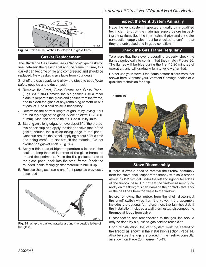
41
Stardance® Direct Vent/Natural Vent Gas Heater
30004968
ST208 �glass swivel latch �12/99
ST208
Fig. 84 Release the latches to release the glass frame.
Gasket ReplacementThe Stardance Gas Heater uses a ‘tadpole’ type gasket to seal between the glass panel and the frame. In time, this gasket can become brittle and compressed and should be replaced. New gasket is available from your dealer.Shut off the gas supply and allow the stove to cool. Wear safety goggles and a dust mask.1. Remove the Front, Glass Frame and Glass Panel.
(Figs. 83 & 84) Remove the old gasket. Use a razor blade to separate the glass and gasket from the frame, and to clean the glass of any remaining cement or bits of gasket. Use a cold chisel if necessary.
2. Determine the correct length of gasket by laying it out around the edge of the glass. Allow an extra 1 - 2” (25-50mm). Mark the spot to be cut. Use a utility knife.
3. Starting on a long edge, remove about 6” of the protec-tive paper strip and apply the flat adhesive face of the gasket around the outside-facing edge of the panel. Continue around the panel, applying a bout 6” at a time and being careful to not stretch the material. Do not overlap the gasket ends. (Fig. 85)
4. Apply a thin bead of high temperature silicone rubber sealant along the inside corner of the glass frame, all around the perimeter. Place the flat gasketed side of the glass panel back into the steel frame. Pinch the rounded inside-facing gasket material to bulk it up.
5. Replace the glass frame and front panel as previously described.
ST179 �glass gasket detail �11/99
ST179
Fig. 85 Wrap the gasket material around the outside iedge of the glass.
Inspect the Vent System AnnuallyHave the vent system inspected annually by a qualified technician. Shut off the main gas supply before inspect-ing the system. Both the inner exhaust pipe and the outer combustion supply pipe must be checked to confirm that they are unblocked and in good condition.
Check the Gas Flame RegularlyTo ensure that the stove is operating properly, check the flames periodically to confirm that they match Figure 86. The flames will be blue during the first 15-20 minutes of operation, and will gradually turn to yellow after that.Do not use your stove if the flame pattern differs from that shown here. Contact your Vermont Castings dealer or a qualified technician for help.
Stove DisassemblyIf there is ever a need to remove the firebox assembly from the stove shell, support the firebox with solid stands about 6” (152 mm) tall under the left and right outer edges of the firebox base. Do not set the firebox assembly di-rectly on the floor; this can damage the control valve and/or the gas lines from the valve to the firebox.Before removing the firebox from the shell, disconnect the on/off switch wires from the valve. If the assembly includes the optional fan, disconnect the fan rheostat. If the installation includes a wall thermostat, disconnect the thermostat leads from valve.Disconnection and reconnection to the gas line should only be done by a qualified gas service technician.Upon reinstallation, the vent system must be sealed to the firebox as shown in the installation section, Page 14. Also be sure the logs are placed in the firebox correctly, as shown on Page 25, Figures 46-49.
Figure 86
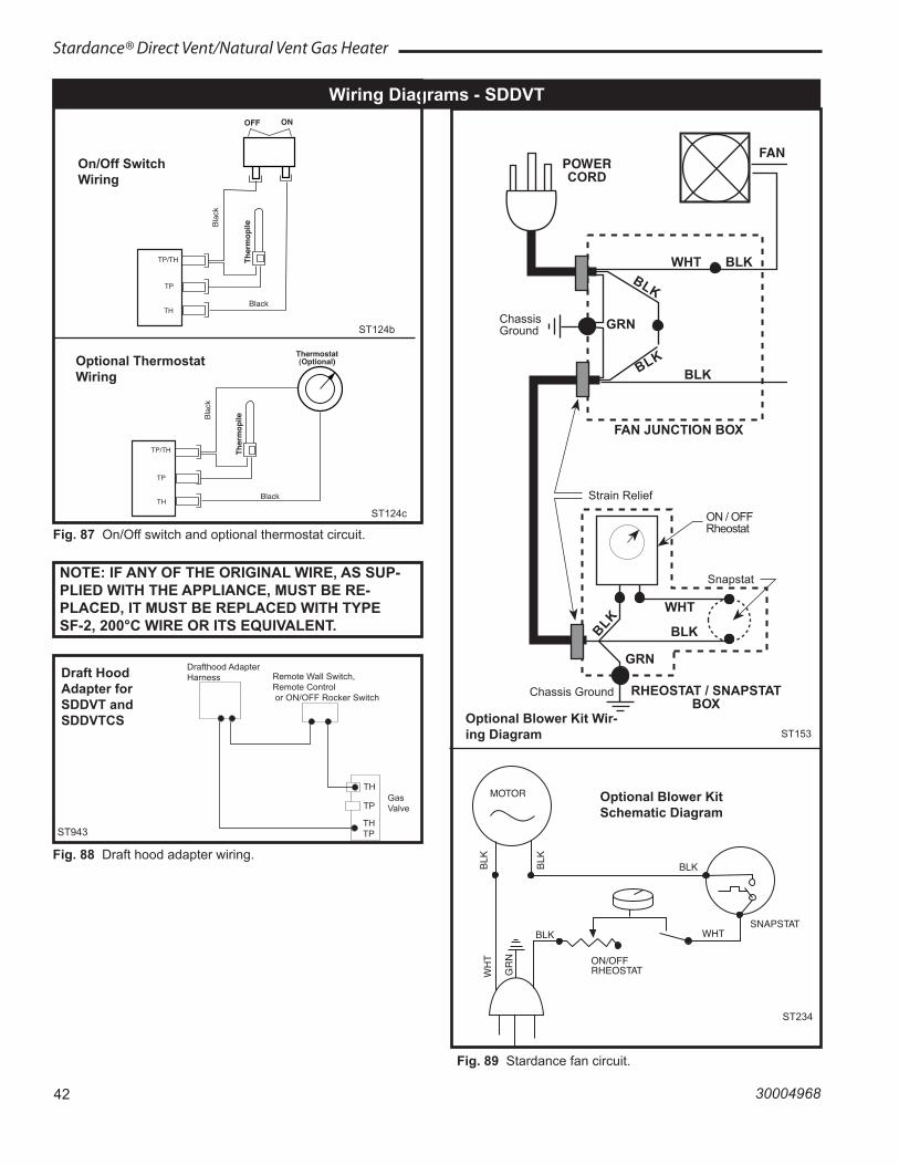
42
Stardance® Direct Vent/Natural Vent Gas Heater
30004968
OFF ON
Thermostat �(Optional)
� Ther
mop
ileBlac
k
Black
Millivolt �Gas Valve
St124b �on/off/switch �wiring �1/11/00 djt
TP/TH
TP
TH
Wiring Diagrams - SDDVT
ST124b
On/Off Switch Wiring
Thermostat �(Optional)
� Ther
mop
ileBlac
k
Black
Millivolt �Gas Valve
St124c �Thermostat �wiring �1/11/00 djt
TP/TH
TP
TH
Optional Thermostat Wiring
ST124c
Fig. 87 On/Off switch and optional thermostat circuit.
NOTE: IF ANY OF THE ORIGINAL WIRE, AS SUP-PLIED WITH THE APPLIANCE, MUST BE RE-PLACED, IT MUST BE REPLACED WITH TYPE SF-2, 200°C WIRE OR ITS EQUIVALENT.
FAN JUNCTION BOX
FANPOWERCORD
Strain Relief
Chassis Ground
BLK
GRN
GRN
WHT
ON / OFFRheostat
ChassisGround
RHEOSTAT / SNAPSTATBOX
Snapstat
BLKBLK
BLK
BLKBLK
WHT
ST153 rdv connections diag.10/99
MOTOR
SNAPSTAT
ON/OFFRHEOSTAT
WHT
WH
T
BLKBLK
BLK
GR
N
BLK
ST236 �FK26 wiring diagram �12/99
Optional Blower Kit Schematic Diagram
ST234
ST153
Fig. 89 Stardance fan circuit.
Optional Blower Kit Wir-ing Diagram
ST943
Fig. 88 Draft hood adapter wiring.
ST943FSDHAG Wiring 6/07
Drafthood Adapter Harness Remote Wall Switch,
Remote Control or ON/OFF Rocker Switch
TH
TP
TH TP
Gas Valve
Draft Hood Adapter for SDDVT and SDDVTCS
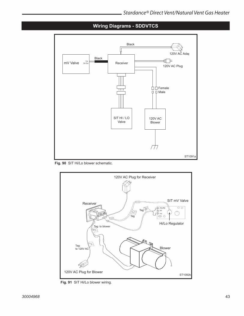
43
Stardance® Direct Vent/Natural Vent Gas Heater
30004968
T HT P / T H
120V AC Adapter
mV Valve
Black
Black
SIT HI / LOValve
FemaleMale
ST1090SIT valve wiring
120V AC Plug
120V ACBlower
Receiver
Fig. 90 SIT Hi/Lo blower schematic.
ST1091a
120V AC Plug for Receiver
Receiver
120V AC Plug for Blower
Blower
SIT mV Valve
Hi/Lo RegulatorTag: to blower
Tag
Tag
ST1092bSIT valve schematic
Tag:to 120V AC
ST1092b
Fig. 91 SIT Hi/Lo blower wiring.
Wiring Diagrams - SDDVTCS
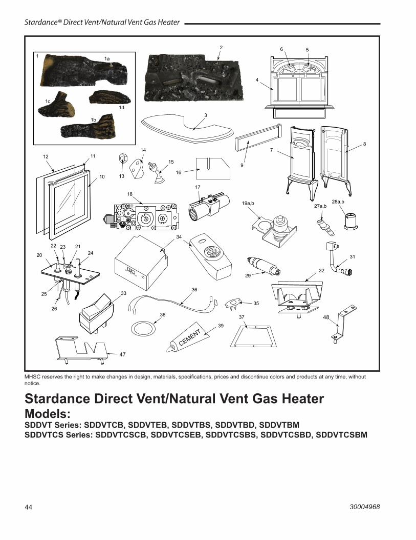
44
Stardance® Direct Vent/Natural Vent Gas Heater
30004968
MHSC reserves the right to make changes in design, materials, specifications, prices and discontinue colors and products at any time, without notice.
Stardance Direct Vent/Natural Vent Gas HeaterModels: SDDVT Series: SDDVTCB, SDDVTEB, SDDVTBS, SDDVTBD, SDDVTBMSDDVTCS Series: SDDVTCSCB, SDDVTCSEB, SDDVTCSBS, SDDVTCSBD, SDDVTCSBM
1a
1b
1c
CEMENT39
12 11
10
3336
4968StardanceSDDVT/TCS parts8/09
28a,b
37
9
3
4
6 5
20
22 23 21 24
26
25
35
31
38
7 8
17 18
29
1d
1
2
16
32
13
14
15
27a,b
47
48
OFF
FAN
ON
AUTO
FLAME
ON
RSOFF
34
19a,b
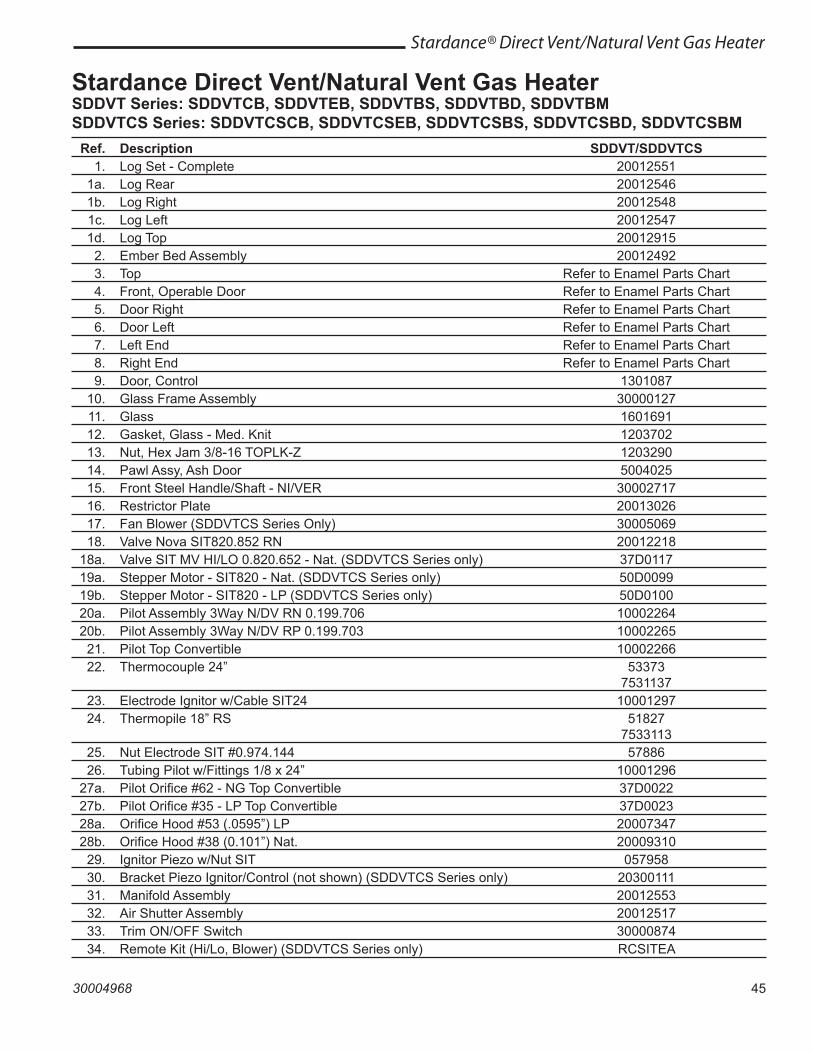
45
Stardance® Direct Vent/Natural Vent Gas Heater
30004968
Ref. Description SDDVT/SDDVTCS 1. Log Set - Complete 20012551 1a. Log Rear 20012546 1b. Log Right 20012548 1c. Log Left 20012547 1d. Log Top 20012915 2. Ember Bed Assembly 20012492 3. Top Refer to Enamel Parts Chart 4. Front, Operable Door Refer to Enamel Parts Chart 5. Door Right Refer to Enamel Parts Chart 6. Door Left Refer to Enamel Parts Chart 7. Left End Refer to Enamel Parts Chart 8. Right End Refer to Enamel Parts Chart 9. Door, Control 1301087 10. Glass Frame Assembly 30000127 11. Glass 1601691 12. Gasket, Glass - Med. Knit 1203702 13. Nut, Hex Jam 3/8-16 TOPLK-Z 1203290 14. Pawl Assy, Ash Door 5004025 15. Front Steel Handle/Shaft - NI/VER 30002717 16. Restrictor Plate 20013026 17. Fan Blower (SDDVTCS Series Only) 30005069 18. Valve Nova SIT820.852 RN 20012218 18a. Valve SIT MV HI/LO 0.820.652 - Nat. (SDDVTCS Series only) 37D0117 19a. Stepper Motor - SIT820 - Nat. (SDDVTCS Series only) 50D0099 19b. Stepper Motor - SIT820 - LP (SDDVTCS Series only) 50D0100 20a. Pilot Assembly 3Way N/DV RN 0.199.706 10002264 20b. Pilot Assembly 3Way N/DV RP 0.199.703 10002265 21. Pilot Top Convertible 10002266 22. Thermocouple 24” 53373 7531137 23. Electrode Ignitor w/Cable SIT24 10001297 24. Thermopile 18” RS 51827 7533113 25. Nut Electrode SIT #0.974.144 57886 26. Tubing Pilot w/Fittings 1/8 x 24” 10001296 27a. Pilot Orifice #62 - NG Top Convertible 37D0022 27b. Pilot Orifice #35 - LP Top Convertible 37D0023 28a. Orifice Hood #53 (.0595”) LP 20007347 28b. Orifice Hood #38 (0.101”) Nat. 20009310 29. Ignitor Piezo w/Nut SIT 057958 30. Bracket Piezo Ignitor/Control (not shown) (SDDVTCS Series only) 20300111 31. Manifold Assembly 20012553 32. Air Shutter Assembly 20012517 33. Trim ON/OFF Switch 30000874 34. Remote Kit (Hi/Lo, Blower) (SDDVTCS Series only) RCSITEA
Stardance Direct Vent/Natural Vent Gas HeaterSDDVT Series: SDDVTCB, SDDVTEB, SDDVTBS, SDDVTBD, SDDVTBMSDDVTCS Series: SDDVTCSCB, SDDVTCSEB, SDDVTCSBS, SDDVTCSBD, SDDVTCSBM
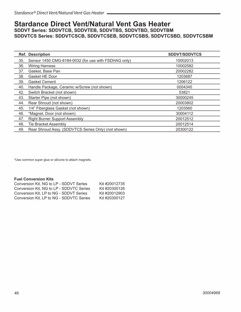
46
Stardance® Direct Vent/Natural Vent Gas Heater
30004968
Stardance Direct Vent/Natural Vent Gas HeaterSDDVT Series: SDDVTCB, SDDVTEB, SDDVTBS, SDDVTBD, SDDVTBMSDDVTCS Series: SDDVTCSCB, SDDVTCSEB, SDDVTCSBS, SDDVTCSBD, SDDVTCSBM
Ref. Description SDDVT/SDDVTCS 35. Sensor 1450 CMG-8184-0032 (for use with FSDHAG only) 10002013 36. Wiring Harness 10002582 37. Gasket, Base Pan 20002282 38. Gasket HE Door 1203687 39. Gasket Cement 1206122 40. Handle Package, Ceramic w/Screw (not shown) 0004345 42. Switch Bracket (not shown) 53821 43. Starter Pipe (not shown) 30000245 44. Rear Shroud (not shown) 20003802 45. 1/4” Fiberglass Gasket (not shown) 1203560 46. *Magnet, Door (not shown) 30004112 47. Right Burner Support Assembly 20012512 48. Tie Bracket Assembly 20012514 49. Rear Shroud Assy. (SDDVTCS Series Only) (not shown) 20300122
Fuel Conversion KitsConversion Kit, NG to LP - SDDVT Series Kit #20012735Conversion Kit, NG to LP - SDDVTC Series Kit #20300126Conversion Kit, LP to NG - SDDVT Series Kit #20012903Conversion Kit, LP to NG - SDDVTC Series Kit #20300127
*Use common super glue or silicone to attach magnets.
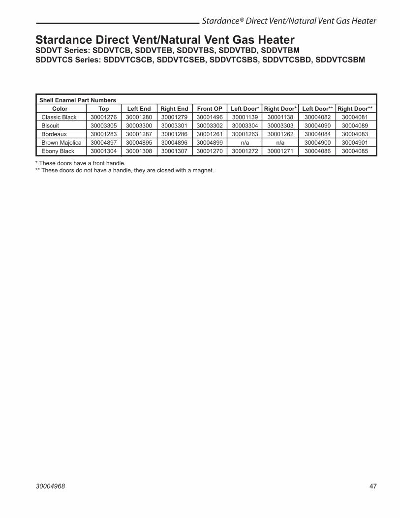
47
Stardance® Direct Vent/Natural Vent Gas Heater
30004968
Shell Enamel Part Numbers Color Top Left End Right End Front OP Left Door* Right Door* Left Door** Right Door** Classic Black 30001276 30001280 30001279 30001496 30001139 30001138 30004082 30004081 Biscuit 30003305 30003300 30003301 30003302 30003304 30003303 30004090 30004089 Bordeaux 30001283 30001287 30001286 30001261 30001263 30001262 30004084 30004083 Brown Majolica 30004897 30004895 30004896 30004899 n/a n/a 30004900 30004901 Ebony Black 30001304 30001308 30001307 30001270 30001272 30001271 30004086 30004085
* These doors have a front handle.** These doors do not have a handle, they are closed with a magnet.
Stardance Direct Vent/Natural Vent Gas HeaterSDDVT Series: SDDVTCB, SDDVTEB, SDDVTBS, SDDVTBD, SDDVTBMSDDVTCS Series: SDDVTCSCB, SDDVTCSEB, SDDVTCSBS, SDDVTCSBD, SDDVTCSBM
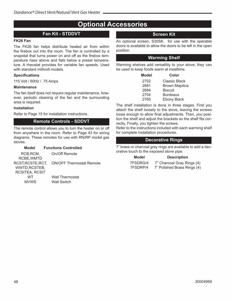
48
Stardance® Direct Vent/Natural Vent Gas Heater
30004968
Optional AccessoriesFan Kit - STDDVT
FK26 FanThe FK26 fan helps distribute heated air from within the firebox out into the room. The fan is controlled by a snapstat that turns power on and off as the firebox tem-perature rises above and falls below a preset tempera-ture. A rheostat provides for variable fan speeds. Used with standard millivolt models.Specifications115 Volt / 60Hz / .75 AmpsMaintenanceThe fan itself does not require regular maintenance, how-ever, periodic cleaning of the fan and the surrounding area is required.InstallationRefer to Page 15 for installation instructions.
Remote Controls - SDDVTThe remote control allows you to turn the heater on or off from anywhere in the room. Refer to Page 43 for wiring diagrams. These remotes for use with RN/RP model gas stoves. Model Functions Controlled RCB,RCM, On/Off Remote RCBE,WMTD RCST,RCSTE,RCT, ON/OFF Thermostat Remote WWTD,RCSTEB, RCSITEA, RCSIT WT Wall Thermostat MVWS Wall Switch
Screen KitAn optional screen, S30SK, for use with the operable doors is available to allow the doors to be left in the open position.
Warming ShelfWarming shelves add versatility to your stove; they can be used to keep foods warm at mealtime. Model Color 2702 Classic Black 2681 Brown Majolica 2684 Biscuit 2704 Bordeaux 2765 Ebony BlackThe shelf installation is done in three stages. First you attach the shelf loosely to the stove, leaving the screws loose enough to allow final adjustments. Then, you posi-tion the shelf and adjust the brackets so the shelf fits cor-rectly. Finally, you tighten the screws.Refer to the instructions included with each warming shelf for complete installation procedures.
Decorative Rings7” brass or charcoal gray rings are available to add a dec-orative touch to the exposed stove pipe. Model Description 7FSDRG/4 7” Charcoal Gray Rings (4) 7FSDRP/4 7” Polished Brass Rings (4)
49
Stardance® Direct Vent/Natural Vent Gas Heater
30004968
50
Stardance® Direct Vent/Natural Vent Gas Heater
30004968
51
Stardance® Direct Vent/Natural Vent Gas Heater
30004968
LIMITED LIFETIME WARRANTY MHSC warrants that all cast iron parts, the combustion chamber,
ceramic burner, and heat exchanger of every Vermont Castings gas product will be free of defective material or workmanship during the period the product is owned by the original owner subject to proof of purchase and the conditions and limitations listed on this warranty document.
BASIC ONE-YEAR WARRANTY MHSC warrants to the original owner that your new Vermont
Castings Gas Appliance is free from defects in material or workmanship for a period of one year from the date of purchase, subject to the following conditions and limitations. Labor to replace these parts is covered for one year, reimbursed per our warranty service fee schedule.
COMPONENT WARRANTY LIMITATATIONSPORCELAIN ENAMEL FINISHED PARTS: MHSC offers no
warranty on chipping of enamel surfaces. Inspect all products prior to accepting them for any damage to the enamel. The salt air environment of coastal areas or a high humidity environment can be corrosive to the porcelain enamel finish. These conditions can cause rusting of the cast iron beneath the porcelain enamel finish, which will cause the finish to flake off. Color lot variations with parts and/or accessories can occur and are not covered by warranty.
GLASS: Glass is not warranted for breakage due to misuse or accident. Glass is not covered for discoloration or stains due to environmental issues, or improper cleaning and maintenance.
PLATED PARTS AND ACCESSORIES: Brass, nickel, and gold parts should be cleaned with Lemon oil only. Commercial cleaners cannot be used. Mortar mix and masonry cleaners corrode the brass finish. The MHSC will not be responsible for, nor will it warrant any brass parts which are damaged by external chemicals or down draft conditions.
ACCESSORIES: Unless otherwise noted, MHSC supplied accessories are covered for a period of one year.
GENERAL CONDITIONS AND LIMITATIONS• This Vermont Castings product must be installed or serviced by
a qualified installer, preferably NFI or WETT (Canada) certified, as prescribed by the local jurisdiction. It must be installed and operated at all times in accordance with the Installation and Operating instructions furnished with the product. Any alteration, willful abuse, accident, or misuse of the product shall nullify this warranty.
• This warranty is non-transferable, and is made to the original owner, provided that the purchase was made through an authorized supplier of Vermont Castings branded MHSC products.
• Parts covered under the Limited Lifetime Warranty will be covered for the lifetime of the appliance up to a maximum of seven (7) years after MHSC discontinues the model. The maximum amount recoverable under this warranty is limited to the purchase price of the product and, if MHSC is unable to provide replacement or repair in an expedient and cost effective manner, MHSC may discharge all obligations under this warranty by refunding the purchase price of the product.
• Any labor and related repair charges relating to the cost and expenses of replacing or repairing defective components under the Limited Lifetime Warranty are not covered, except as provided for under the Basic One-Year Warranty.
• Any part or component replaced under the provisions of this warranty is covered for six months or the remainder of the original warranty, whichever is longest.
• Any installation, labor, construction, transportation, or other related costs/expenses arising from defective part(s), repair, replacement, or otherwise of same, will not be covered by this warranty, nor shall the Company assume responsibility for same. IN NO EVENT SHALL MHSC BE LIABLE FOR ANY INCIDENTAL OR CONSEQUENTIAL DAMAGES CAUSED BY DEFECTS IN THE PRODUCT except as provided by law
• SOME STATES DO NOT ALLOW FOR THE EXCLUSION OR LIMITATIONS OF INCIDENTAL AND CONSEQUENTIAL DAMAGES OR LIMITATIONS ON HOW LONG AN IMPLIED WARRANTY LASTS, SO THE ABOVE LIMITATIONS MAY NOT APPLY TO YOUR CIRCUMSTANCES. THIS WARRANTY GIVES YOU SPECIFIC RIGHTS AND YOU MAY HAVE OTHER RIGHTS WHICH VARY FROM STATE TO STATE.
• All other warranties expressed or implied with respect to the product, its components and accessories, or any obligations/liabilities on the part of the Company are hereby expressly excluded.
• The Company neither assumes, nor authorizes any third party to assume on its behalf, any other liabilities with respect to the sale of this Vermont Castings product
• The warranties as outlined within this document do not apply to chimney components or other non MHSC accessories used in conjunction with the installation of this product.
• Damage to the unit while in transit is not covered by this warranty but is subject to claim against the common carrier. Contact the dealer from whom you purchased your fireplace/stove (do not operate the appliance as this might negate the ability to process the claim with the carrier).
• The Company will not be responsible for:a) Down drafts or spillage caused by environmental conditions such
as near-by trees, buildings, roof tops, hills, or mountains.b) Inadequate ventilation or negative air pressure caused by
mechanical systems such as furnaces, fans, clothes dryers, etc.• This warranty is void if:a) The fireplace has been operated in atmospheres contaminated
by chlorine, fluorine, or other damaging chemicals.b) The fireplace has been subjected to prolonged periods of
dampness or condensationc) Any damages to the fireplace, combustion chamber, heat
exchanger or other components due to water, or weather damage, which is the result of but not limited to, improper chimney/venting installation.
d) Any alteration, willful abuse, accident, or misuse of the product has occurred.
IF WARRANTY SERVICE IS NEEDED... Contact your installing Vermont Castings dealer. Make sure
you have your warranty, your sales receipt, the model number and serial number of your MHSC product. If you’re the installing dealer is unknown or unable to provide necessary parts or service, a list of Authorized Vermont Casting dealers can be located on the internet at www.vermontcastings.com
LIMITED LIFETIME WARRANTY PRODUCT COVERED BY THIS WARRANTYAll Vermont Castings brand gas stoves, gas inserts, and gas fireplaces installed in the United States of America or Canada.
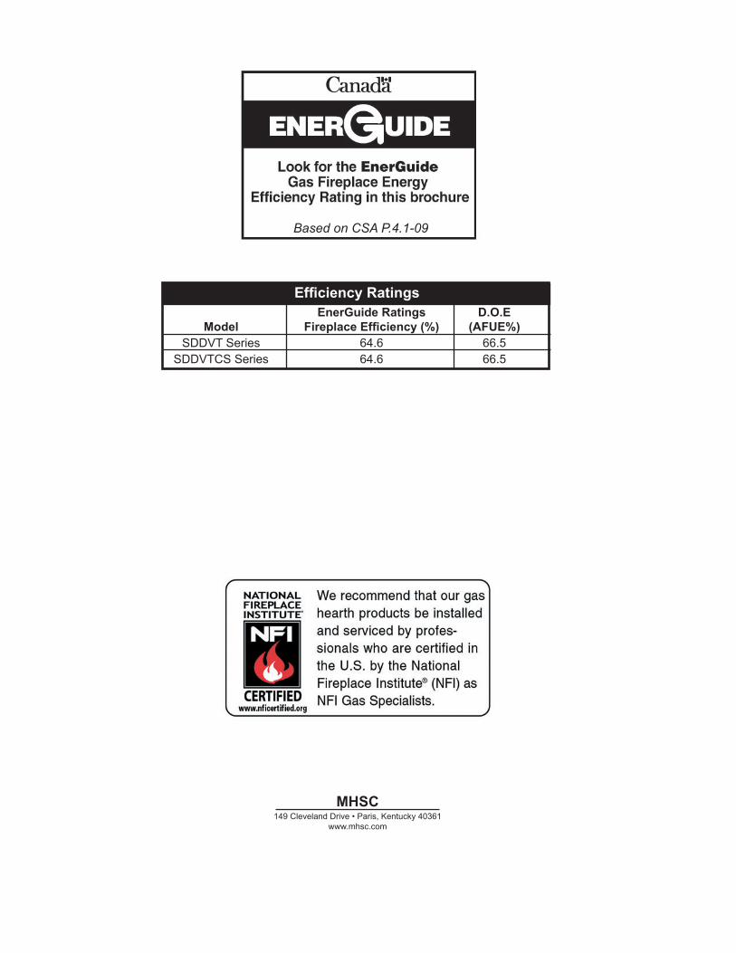
MHSC149 Cleveland Drive • Paris, Kentucky 40361
www.mhsc.com
Based on CSA P.4.1-09
Based on CSA P.4.1-09
Recherchez dans la brochureles caractéristique de rendement
énergétique de foyer au gazÉnerguide
Selon CSA P.4.1-09
Efficiency Ratings EnerGuide Ratings D.O.E Model Fireplace Efficiency (%) (AFUE%) SDDVT Series 64.6 66.5 SDDVTCS Series 64.6 66.5