Embed Size (px)
Citation preview

LUXEON® K
LUXEON KAssembly and Handling Information
Application Brief AB102
Introduction
This application brief covers recommended assembly and handling procedures for LUXEON K array emitters.
LUXEON K emitters are designed to deliver high luminous flux and efficacy in an easy-to-use bolt-down
package that facilitates assembly in space-constrained retrofit and down-light applications. Proper assembly,
handling, and thermal management, as outlined in this Application Brief, ensures high optical output and long
LED lumen maintenance for LUXEON K emitters.
ScopeThe assembly and handling guidelines in this Application Brief apply to the following products:
• LUXEON K 4-up (LXK8-PWxx-0004)• LUXEON K 8-up (LXK8-PWxx-0008)• LUXEON K 12-up (LXK8-PWxx-0012)• LUXEON K 16-up (LXK8-PWxx-0016)• LUXEON K 24-up (LXK8-PWxx-0024)
Any assembly or handling requirements that are specific to a subset of LUXEON K products is clearly marked.
In the remainder of this document the term LUXEON K simply refers to any product in the LUXEON K
product family.
Assembly and Handling Information
LUXEON K Assembly and Handling Application Brief AB102 20121220 2
1. Component ..............................................................................................................................................................3
1.1 Description ........................................................................................................................................................3
1.2 Optical Center ..................................................................................................................................................3
1.3 Handling Precautions .......................................................................................................................................3
1.4 Cleaning ..............................................................................................................................................................3
1.5 Electrical Isolation ............................................................................................................................................3
1.6 Mechanical Files ................................................................................................................................................3
1.7 Soldering .............................................................................................................................................................3
2. Assembly Process .....................................................................................................................................................5
2.1 Mounting LUXEON K Onto a Heat Sink ..................................................................................................5
2.2 LUXEON K Solderless LED Socket ...........................................................................................................5
2.3 Mounting LUXEON K Directly Onto a Heat Sink ..................................................................................9
3. Thermal Management ............................................................................................................................................10
3.1 Thermal Interface Materials (TIM) Selection ..........................................................................................10
3.2 Heat Sink .........................................................................................................................................................11
3.3 Temperature Probing and Characterization .............................................................................................11
3.4 Thermal Measurements ................................................................................................................................12
4. Product Packaging Considerations—Chemical Compatibility ...................................................................13
Table of Contents

LUXEON K Assembly and Handling Application Brief AB102 20121220 3
1. Component 1.1 Description
The LUXEON K emitter consists of an array of LED chips which are mounted onto a metal-core printed circuit board (MCPCB) to facilitate
assembly and handling. The MCPCB is made out of aluminum to ensure a good thermal path between the LEDs and the heatsink on which
LUXEON K is mechanically mounted. The MCPCB of the LUXEON K emitter contains 2 slots for mounting screws (marked by dashed black lines)
and 2 smaller slots to feed electrical wires to the electrical pads on top of the substrate.
The LED array is overmolded with silicone to enhance light extraction and to shield the chip array from the environment. LUXEON K emitters
include a transient voltage suppressor (TVS) chip under the silicone to protect the emitter against electrostatic discharge (ESD).
The backside of the MCPCB contains a serial number and a 2D barcode which is unique to each emitter.
LUXEON K emitters come in various form factors in order to meet different performance specifications. Figure 1 summarizes the key mechanical
features for each LUXEON K emitter configuration.
1.2 Optical Center
The optical center of all LUXEON K emitters coincides with the mechanical center of the emitter.
Optical rayset data for each LUXEON K emitter are available upon request.
1.3 Handling Precautions
LUXEON K emitters are designed to maximize light output and reliability. However, improper handling of the emitter may damage the silicone
overmold and affect the overall performance and reliability. In order to minimize the risk of damage to the silicone overmold during handling,
LUXEON K emitters should only be picked up from the MCPCB. Excessive force on the lens may cause damage to the interior of the
LUXEON K emitter.
1.4 Cleaning
LUXEON K emitters should not be exposed to dust and debris. Excessive dust and debris may cause a drastic decrease in optical output. In the
event that a LUXEON K emitter requires cleaning, first try a gentle swabbing using a lint-free swab. If needed, a lint-free swab and isopropyl alcohol
(IPA) can be used to gently remove dirt from the lens. Do not use other solvents as they may adversely react with the LED assembly. For more
information regarding chemical compatibility, see Section 4.
1.5 Electrical Isolation
The aluminum substrate of the LUXEON K emitter is electrically isolated from the LED cathode and anode.
1.6 Mechanical Files
Mechanical drawings for LUXEON K (2D and 3D) are available upon request.
1.7 Soldering
LUXEON K emitters are designed to be mechanically secured onto a heat sink. Electrical wires may have to be soldered onto the electrical pads.
For detailed assembly instructions, see Section 2.

LUXEON K Assembly and Handling Application Brief AB102 20121220 4
Figure 1. Mechanical and thermal characteristics by LUXEON K emitter configuration.
LUXEON K 4-up (LXK8-PWxx-0004) LUXEON K 8-up (LXK8-PWxx-0008)
Circular substrate: 19.0mm
Distance d for M2 screws: d = 15.0mm Distance d for M3 screws: d = 17.0mm
= 4.0K/W
Circular substrate: 23.0mm Distance d for M2 screws: d = 19.7mm Distance d for M3 screws: d = 21.7mm
= 1.5K/W LUXEON K 12-up (LXK8-PWxx-0012) LUXEON K 16-up (LXK8-PWxx-0016)
Circular substrate: 25.0mm
Distance d for M2 screws: d = 22.0mm Distance d for M3 screws: d = 24.0mm
= 1.1K/W
Circular substrate: 25.0mm Distance d for M2 screws: d = 22.0mm Distance d for M3 screws: d = 24.0mm
= 0.9K/W LUXEON K 24-up (LXK8-PWxx-0024)
Square substrate: 30mm x 30mmDistance d for M2 screws: d = 28.3mm Distance d for M3 screws: d = 30.2mm
= 0.6K/W

LUXEON K Assembly and Handling Application Brief AB102 20121220 5
2. Assembly Process2.1 Mounting LUXEON K Onto a Heat Sink
LUXEON K emitters are designed to be mechanically mounted onto a heat sink with screws, facilitating the design and assembly of retrofit and
down-light applications. TE Connectivity1 offers a special LUXEON K solderless LED Socket from, which can be used to electrically, mechanically and
thermally secure a LUXEON K emitter onto a heat sink, see Figure 2. Alternatively, a LUXEON K emitter can be directly mounted onto a heat sink
with M2/M3 screws and electrical wires can be soldered onto the electrical pads. The remainder of this section provides detailed instructions on
how to mount the LUXEON K emitter onto a heat sink.
2.2 LUXEON K Solderless LED Socket
The TE Connectivity Solderless LED Socket (Type LK 2173470-1) is designed to scale with all sizes and models of the LUXEON K emitter.
A LUXEON K emitter can be mechanically secured onto a heat sink with two TE Connectivity LED Sockets. The square LUXEON K 24-up emitter
requires one additional M3 screw to ensure good mechanical contact between the emitter and the heat sink. Each Solderless LED socket includes
a metal spring connector, which is designed to establish a reliable electrical contact between the Socket and one of the electrical pads on the
LUXEON K emitter, and an easy-to-use poke-in wire termination, which is compatible with 22-24 AWG wires. Figure 3 provides relevant reference
dimensions for the TE Connectivity Solderless LED Socket. Figure 4 and Figure 5 provide reference layouts and dimensions for the holes that need
to be drilled into the heat sink to align and secure a LUXEON K emitter onto a heat sink with the Solderless LED Sockets.
The Solderless LED Socket (Type LK 2173470-1) is designed and manufactured by TE Connectivity and may be subject to change without notice.
The assembly information for the Solderless LED Socket discussed in this document is for reference only. For the latest up-to-date information on
the Solderless LED Socket, visit http://www.te.com/catalog/pn/en/2173470-1. Philips Lumileds provides no warranty of any kind with respect to the
Solderless LED Socket.
___________________________
1 TE Connectivity, TE Connectivity (logo) and TE (logo) are trademarks of the TE Connectivity Ltd family of companies.
Figure 2. The TE Connectivity Solderless LED Holder (Type LK 2173470-1).
TE Sockets
LUXEON K emitter
Threadedholes for mounting
the TE SocketSocket
Heat sinkLocator Alignment

LUXEON K Assembly and Handling Application Brief AB102 20121220 6
Figure 3. Reference dimensions for the TE Connectivity Solderless LED Holder (Type LK 2173470-1). All dimensions are in mm.
Figure 4. Reference layout and dimensions of the holes that need to be drilled into the heat sink to align and secure the
LUXEON K 4-up, 8-up, and 12-up emitter with the Solderless LED Holder (Type LK 2173470-1). All dimensions are in mm.

LUXEON K Assembly and Handling Application Brief AB102 20121220 7
Follow these steps to mount the LUXEON K emitter on a heat sink with the Solderless LED Socket (Type LK 2173470-1) from TE Connectivity:
1. Prepare the heat sink
a. Ensure that the heat sink surface is clean and flat (≤ 25um, with no crowns or peaks in the mounting area).
b. Drill and tap the holes as per Figure 4 or Figure 5 and wipe the heat sink surface clean with isopropyl alcohol (IPA).
c. Apply a thermal interface material (TIM) on the LED area. For more details regarding suitable TIMs, see Section 3.1.
2. Align the semi-circular cutouts in the LUXEON K board, which are closest to the electrical pads, with the pre-drilled screw holes in the heat
sink (see Figure 6).
Figure 5. Reference layout and dimensions of the holes that need to be drilled into the heat sink to align and secure
the LUXEON K 16-up, and 24-up emitter with the Solderless LED Holder (Type LK 2173470-1). All dimensions are in mm.
Figure 6. Align the LUXEON K emitter with respect to the tapped screw holes on the heat sink.
Heat Sink with the predrilled hole pattern
Screw holes

LUXEON K Assembly and Handling Application Brief AB102 20121220 8
3. Secure the LUXEON K emitter with two TE Solderless LED Sockets (see Figure 7).
a. Place the Solderless LED Sockets over the LUXEON K emitter such that the alignment pins of the Solderless LED Sockets mate with the
alignment holes in the heat sink.
b. Secure each TE Solderless LED Socket onto the heat sink with an M3 screw. The screw down torque should not exceed 4.0 inch lbs.
c. In addition to the two TE Solderless LED Sockets, a LUXEON K 24-up emitter should be secured with a third M3 screw in the pre-drilled
hole in the heat sink.
4. Terminate the wires (see Figure 8).
a. Prepare the trip length of the wire. This should be 6.95mm long.
b. Insert one of the 22/24 AWG UL1007 style wires into the opening of the connector.
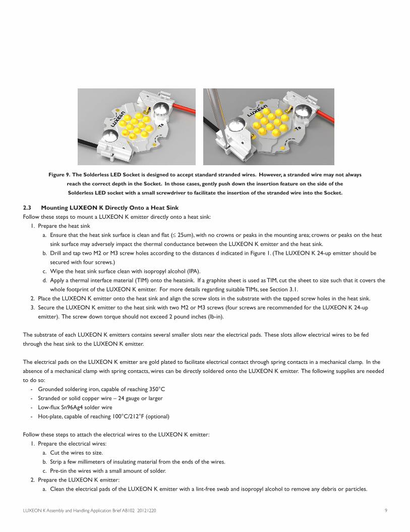
c. The Solderless LED Socket is designed to accept standard stranded wires. However, a stranded wire may not always reach the correct
depth in the Socket. In those cases, gently push down the insertion feature on the side of the Solderless LED socket with a small
screwdriver to facilitate the insertion of the stranded wire into the Socket (see Figure 9).
d. Verify that the wires are inserted to the correct depth.
e. Lead the wires to an appropriate LED Driver.
f. If desired, one or both wires can be tucked into the wire guide feature on the respective Solderless LED Socket.
g. The LUXEON K emitter is now ready for operation.
Figure 7. LUXEON K emitters are secured onto a heat sink with two Solderless LED Holders. Alignment pins
on the Solderless LED Holders are designed to mate with the alignment holes in the heat sink.
Align the TE holder by Secure the TE holdersAlign the TE holder byAlign the TE holder bypushing on the board
Secure the TE holdersAlign the TE holder bypushing on the board
Figure 8. 22/24 AWG UL1007 style wires can be inserted into the Solderless LED
Holder to establish an electrical connection with the LUXEON K emitter.
Direction for wire insertion Stranded Wire Wire Guiding FeaturesDirection for wire insertion
Push
Stranded WireInsertion Feature
Wire Guiding Features
LUXEON K Assembly and Handling Application Brief AB102 20121220 9
2.3 Mounting LUXEON K Directly Onto a Heat Sink
Follow these steps to mount a LUXEON K emitter directly onto a heat sink:
1. Prepare the heat sink
a. Ensure that the heat sink surface is clean and flat (≤ 25um), with no crowns or peaks in the mounting area; crowns or peaks on the heat
sink surface may adversely impact the thermal conductance between the LUXEON K emitter and the heat sink.
b. Drill and tap two M2 or M3 screw holes according to the distances d indicated in Figure 1. (The LUXEON K 24-up emitter should be
secured with four screws.)
c. Wipe the heat sink surface clean with isopropyl alcohol (IPA).
d. Apply a thermal interface material (TIM) onto the heatsink. If a graphite sheet is used as TIM, cut the sheet to size such that it covers the
whole footprint of the LUXEON K emitter. For more details regarding suitable TIMs, see Section 3.1.
2. Place the LUXEON K emitter onto the heat sink and align the screw slots in the substrate with the tapped screw holes in the heat sink.
3. Secure the LUXEON K emitter to the heat sink with two M2 or M3 screws (four screws are recommended for the LUXEON K 24-up
emitter). The screw down torque should not exceed 2 pound inches (lb-in).
The substrate of each LUXEON K emitters contains several smaller slots near the electrical pads. These slots allow electrical wires to be fed
through the heat sink to the LUXEON K emitter.
The electrical pads on the LUXEON K emitter are gold plated to facilitate electrical contact through spring contacts in a mechanical clamp. In the
absence of a mechanical clamp with spring contacts, wires can be directly soldered onto the LUXEON K emitter. The following supplies are needed
to do so:
- Grounded soldering iron, capable of reaching 350°C
- Stranded or solid copper wire – 24 gauge or larger
- Low-flux Sn96Ag4 solder wire
- Hot-plate, capable of reaching 100°C/212°F (optional)
Follow these steps to attach the electrical wires to the LUXEON K emitter:
1. Prepare the electrical wires:
a. Cut the wires to size.
b. Strip a few millimeters of insulating material from the ends of the wires.
c. Pre-tin the wires with a small amount of solder.
2. Prepare the LUXEON K emitter:
a. Clean the electrical pads of the LUXEON K emitter with a lint-free swab and isopropyl alcohol to remove any debris or particles.
Figure 9. The Solderless LED Socket is designed to accept standard stranded wires. However, a stranded wire may not always
reach the correct depth in the Socket. In those cases, gently push down the insertion feature on the side of the
Solderless LED socket with a small screwdriver to facilitate the insertion of the stranded wire into the Socket.

LUXEON K Assembly and Handling Application Brief AB102 20121220 10
b. The substrate of the LUXEON K emitter is designed to dissipate heat quickly. This may make it difficult to get the temperature of
the electrical pads to a point where the solder will reflow. Therefore it is important to place the LUXEON K emitter on a thermally
insulating surface. Alternatively, place the LUXEON K emitter on a pre-heated hot plate set to 100°C/212°F.
c. Place the tip of the soldering iron on the electrical pad, apply solder and allow it to wet the electrical pad. Do not place the soldering
iron on the electrical pad for more than 3 seconds to prevent any damage to the LUXEON K emitter.
3. Solder the pre-tinned wires to the pre-tinned electrical pads:
a. Place the pre-tinned LUXEON K emitter on a thermally insulating surface. Alternatively, place the LUXEON K emitter on a pre-heated
hot plate set to 100°C/212°F.
b. Place the pre-tinned wire on the pre-tinned electrical pad.
c. Place the tip of the soldering iron on the electrical pad and allow the solder to reflow around the wire. Do not place the soldering iron
on the electrical pad for more than 3 seconds to prevent any damage to the LUXEON K emitter. If a solder joint cannot be established
within this time, allow the LUXEON K emitter to cool before reapplying the heat.
d. Remove the soldering iron and allow the solder to joint to cool.
3. Thermal Management3.1 Thermal Interface Materials (TIM) Selection
Due to the low thermal resistance of the LUXEON K emitter and its large thermal footprint, a variety of thermal interface materials can be used to
thermally connect the emitter to the heat sink (e.g. phase change materials, thermal tapes, graphite sheets). However, TIM selection should be made
with the following considerations:
1. Pump out—Some TIMs will move out of the thermal path during extreme temperature excursions and create voids in the thermal path.
These materials should not be used.
2. TIM thickness—Excessive thickness of some TIMs will present an unacceptable thermal resistance even though the thermal conductivity may
be high.
3. Surface roughness—In order to fill the air gaps between adjacent surfaces, choose the appropriate TIM that minimizes the interfacial contact
resistance.
4. Operating temperature—Some TIMs perform poorly at elevated temperatures. Care should be exercised to select a TIM that will perform
well under the anticipated operating conditions.
5. Out-gassing—Out-gassing of some TIMs at design temperatures may produce undesirable optical or appearance qualities (e.g. fogging) in a
sealed system. Special consideration must be given to limit this effect.
6. Clamping force—TIMs such as thermal tape or pads perform better when the right pressure is applied.
Table 1 lists several TIMs that have been tested with LUXEON K. This data is provided for informational purposes only. Philips Lumileds cannot
guarantee the performance of the listed TIMs since LED operating conditions will vary with the application design.
Table 1. List of TIM materials that meet the TIM considerations outlined in this section.
Note, though, that the actual performance of these TIM materials will depend on the final application.
Manufacturer TIM Arctic Silver Arctic Silver® #5
GrafTech Graphite Sheet 1205
Thermalloy Inc. Thermal Joint Compound (white)

LUXEON K Assembly and Handling Application Brief AB102 20121220 11
Table 2. Measured LUXEON K junction temperatures for various drive currents and heat sink configurations.
LUXEON K Heat sink Configuration information TIM Ta [°C] If [mA] Ts [°C] Vf [V] Tj [°C]
Ohmite SA-LED-113E GrafTech 350 44.1 11.5 60
4-up Rth = 5.33°C/W Graphite 25.4 500 52.8 11.7 76
Sheet 700 62.6 11.8 96
Ohmite SA-LED-113E GrafTech 350 61.9 22.1 74
8-up Rth = 5.33°C/W Graphite 23.7 500 78.4 22.0 95
Sheet 700 98.1 22.4 122
Ohmite SA-LED-151E GrafTech 350 52.4 33.1 65
12-up Rth = 3.2°C/W Graphite 23.9 500 63.3 33.4 82
Sheet 700 86.9 33.8 113
Ohmite SA-LED-151E GrafTech 350 60.6 43.6 74
16-up Rth = 3.2°C/W Graphite 24.8 500 74.6 43.9 94
Sheet 700 94.1 44.1 122
Custom GrafTech 350 64.7 65.3 78
24-up Rth ≈ 2°C/W Graphite 25.6 500 79.8 65.7 100
Sheet 700 102.8 66.0 131
3.2 Heat Sink
LUXEON K emitters must be mounted onto a properly sized heat sink in order to keep the junction temperature below the maximum acceptable
junction temperature specified in the datasheet. For reference, Table 2 summarizes the approximate junction temperature which was measured for
each LUXEON K emitter at multiple drive currents on the specified heat sink.
3.3 Temperature Probing and Characterization
The typical thermal resistance Rq(j-c) between the junction and case for the different LUXEON K emitter configurations are published in the
datasheet. With this information, the junction temperature Tj can be calculated according to the following equation:
Tj = Tc + Rqj-c • Pelectrical
In this equation Tc is the case temperature at the bottom of the LUXEON K emitter and Pelectrical is the electrical power going into the
LUXEON K emitter.
In typical applications it may be difficult to measure the case temperature Tc directly. Therefore, a practical way to determine the junction
temperature of a LUXEON K emitter is by measuring the temperature Ts of a predetermined sensor pad with a thermocouple. Each LUXEON K
emitter has a sensor pad area, marked with Ts, on the top of the board, see Figure 1.
The thermal resistance Rqj-s between the sensor pad and the junction of the LUXEON K emitter was experimentally determined. Figure 1
summarizes the typical thermal resistance values for each LUXEON K emitter configuration.

LUXEON K Assembly and Handling Application Brief AB102 20121220 12
3.4 Thermal Measurements
This section describes in detail how to mount a thermocouple onto the LUXEON K emitter in order to determine the junction temperature Tj .
Supplies and Equipment
Below is a list of supplies and equipment that is needed for Tj measurements:
- Type T precision fine wire (0.003” gauge diameter) thermal couple from Omega Engineering Inc. (part number: 5SRTC-TT-T-40-36)
- Eccobond one component, low temperature curing, thermal conductive epoxy adhesive from Emerson and Cuming (part number: E 3503-1)
or Arctic Alumina Thermal Adhesive compound from Arctic Silver Inc. (part number: AATA-5G)
- Disposable 3CC barrel syringe from EFD Inc. (part number 5109LL-B)
- Disposable 0.016” inner diameter fine needle tip from EFC Inc. (part number:5122-B)
- Kapton tape
- Convection oven (for curing of Eccobond epoxy)
- Thermometer
- Magnifying glass or low power microscope (e.g. 5x to 30x)
Thermocouple Mounting Procedure
1. Familiarize yourself with the manufacturer’s Material Safety Data Sheet (MSDS) and preparation procedures for the epoxy or adhesive
compound.
2. Place the thermocouple tip on the sensor pad area Ts (see Figure 1). The thermocouple must touch the substrate of the LUXEON K
emitter to ensure an accurate reading.
3. Use Kapton tape to secure the thermocouple wire onto the LUXEON K emitter.
4. Follow step a or b below depending on the compound or adhesive that is used to thermally connect the thermocouple to the
LUXEON K emitter.
a. Eccobond Thermal Adhesive Epoxy
i. Thaw the thermal conductive epoxy per manufacturer’s recommendations.
ii. Dispense sufficient epoxy into the 3CC barrel syringe with the fine needle tip. Store the balance per manufacturer’s
recommendations.
iii. Drop a small amount of thermal conductive epoxy just enough to cover the thermocouple tip.
iv. Cure the epoxy per the manufacturer’s recommendations. Make sure that the oven temperature does not exceed the maximum
rated temperature of the LUXEON K emitter.
v. Let the board cool down to room temperature before starting any measurements.
b. Arctic Alumina Thermal Adhesive compound
i. Since this is a two part epoxy system with an approximate pot-life at room temperature after mixing of 3-4 minutes, make sure that
proper setup is done to ensure that the epoxy can be dispensed within the pot-life span.
ii. After mixing, put the epoxy immediately into the 3CC barrel syringe with the fine needle tip and dispense onto the thermocouple tip.
Close to the end of the pot-life, it becomes difficult to dispense.
iii. Alternatively, you can dip the fine needle tip into the epoxy mix and then “touch” the thermocouple tip to dispense the epoxy via
surface tension.
iv. Cure the epoxy at room temperature (25°C) for at least two hours.
5. Once the epoxy/compound has hardened, the LUXEON K emitter can be mechanically mounted onto the heat sink as explained in Section 2.
6. Plug in the thermocouple connector to the thermometer. The thermocouple now measures the temperature Ts.
7. Connect the power supply to the LUXEON K emitter and power up the emitter with a drive current that corresponds to normal operating
conditions. If possible, attach all fixtures (e.g. heat sink, lens and any cover) to closely simulate the actual application environment.

LUXEON K Assembly and Handling Application Brief AB102 20121220 13
8. Record the temperature Ts once the LUXEON K emitter stabilizes. This may take several minutes or more depending on the overall design
and thermal mass.
9. The junction temperature can then be estimated as follows:
Tj = Ts + Rqj-s • Pelectrical
4. Product Packaging Considerations—Chemical Compatibility The LUXEON K package contains a silicone overcoat and dome to protect the LED chips and extract the maximum amount of light. As with most
silicones used in LED optics, care must be taken to prevent any incompatible chemicals from directly or indirectly reacting with the silicone.
The silicone overcoat in LUXEON K is gas permeable. Consequently, oxygen and volatile organic compound (VOC) gas molecules can diffuse into
the silicone overcoat. VOCs may originate from adhesives, solder fluxes, conformal coating materials, potting materials and even some of the inks
that are used to print the PCBs.
Some VOCs and chemicals react with silicone and produce discoloration and surface damage. Other VOCs do not chemically react with the silicone
material directly but diffuse into the silicone and oxidize during the presence of heat or light. Regardless of the physical mechanism, both cases may
affect the total LED light output. Since silicone permeability increases with temperature, more VOCs may diffuse into and/or evaporate out from
the silicone.
Careful consideration must be given to whether LUXEON K emitters are enclosed in an “air tight” environment or not. In an “air tight”
environment, some VOCs that are introduced during assembly may permeate and remain in the silicone dome. Under heat and “blue” light, the
VOCs inside the dome may partially oxidize and create a silicone discoloration, particularly on the surface of the LED where the flux energy is the
highest. In an air rich or “open” air environment, VOCs have a chance to leave the area (driven by the normal air flow). Transferring the devices
which are discolored in an enclosed environment back to “open” air may allow the oxidized VOCs to diffuse out of the silicone dome and may
restore the original optical properties of the LED.
Determining suitable threshold limits for the presence of VOCs is very difficult since these limits depend on the type of enclosure used to house the
LEDs and the operating temperatures. Also, some VOCs can photo-degrade over time.

LUXEON K Assembly and Handling Application Brief AB102 20121220 14
Table 3. List of commonly used chemicals that will damage the silicone dome of LUXEON K.
Avoid using any of these chemicals in the housing that contains the LED package.
Chemical Name Normally Used as hydrochloric acid acid
sulfuric acid acid
nitric acid acid
acetic acid acid
sodium hydroxide alkali
potassium hydroxide alkali
ammonia alkali
MEK (Methyl Ethyl Ketone) solvent
MIBK (Methyl Isobutyl Ketone) solvent
Toluene solvent
Xylene solvent
Benzene solvent
Gasoline solvent
Mineral spirits solvent
dichloromethane solvent
tetracholorometane solvent
Castor oil oil
lard oil
linseed oil oil
petroleum oil
silicone oil oil
halogenated hydrocarbons (containing F, Cl, Br elements) misc
rosin flux solder flux
acrylic tape adhesive
Table 3 provides a list of commonly used chemicals that should be avoided as they may react with the silicone material. Note that Philips Lumileds
does not warrant that this list is exhaustive since it is impossible to determine all chemicals that may affect LED performance.
The chemicals in Table 3 are typically not directly used in the final products that are built around LUXEON K LEDs. However, some of these
chemicals may be used in intermediate manufacturing steps (e.g. cleaning agents). Consequently, trace amounts of these chemicals may remain on
(sub)components, such heat sinks. Philips Lumileds, therefore, recommends the following precautions when designing your application:
- When designing secondary lenses to be used over an LED, provide a sufficiently large air-pocket and allow for “ventilation” of this air away
from the immediate vicinity of the LED.
- Use mechanical means of attaching lenses and circuit boards as much as possible. When using adhesives, potting compounds and coatings,
carefully analyze its material composition and do thorough testing of the entire fixture under High Temperature over Life (HTOL) conditions.

DisclaimerPHILIPS LUMILEDS LIGHTING COMPANY shall not be liable for any kind of loss of data or any other damages, direct, indirect or consequential, resulting from the use of the provided information and data. Although PHILIPS LUMILEDS LIGHTING COMPANY has attempted to provide the most accurate information and data, the materials and services information and data are provided “as is” and PHILIPS LUMILEDS LIGHTING COMPANY neither warranties, nor guarantees the contents and correctness of the provided information and data. PHILIPS LUMILEDS LIGHTING COMPANY reserves the right to make changes without notice. You as user agree to this disclaimer and user agreement with the download or use of the provided materials, information and data.
Company Information
©2012 Philips Lumileds Lighting Company. All rights reserved. Product specifications are subject to change without notice.
www.philipslumileds.com
www.philipslumileds.cn.com
Philips Lumileds is a leading provider of LEDs for everyday lighting applications. The company’s records for light output,
efficacy and thermal management are direct results of the ongoing commitment to advancing solid-state lighting technology
and enabling lighting solutions that are more environmentally friendly, help reduce CO2 emissions and reduce the need for
power plant expansion. Philips Lumileds LUXEON® LEDs are enabling never before possible applications in outdoor lighting,
shop lighting, home lighting, consumer electronics, and automotive lighting.
Philips Lumileds is a fully integrated supplier, producing core LED material in all three base colors, (Red, Green, Blue) and
white. Philips Lumileds has R&D centers in San Jose, California and in the Netherlands, and production capabilities in
San Jose, Singapore and Penang, Malaysia. Founded in 1999, Philips Lumileds is the high flux LED technology leader and is
dedicated to bridging the gap between solid-state technology and the lighting world. More information about the company’s
LUXEON LED products and solid-state lighting technologies can be found at www.philipslumileds.com.