Embed Size (px)
Citation preview

Galaxy Power System 2424(GPS 2424)
H569-437
User’s GuideSelect Code 167-792-159Comcode 108305251Issue 5June 2000© 2000 Lucent Technologies


User’s GuideSelect Code 167-792-159Comcode 108305251Issue 5June 2000
Lucent TechnologiesGalaxy Power System 2424
(GPS 2424)H569-437
Notice:Every effort was made to ensure that the information in this document was complete and accurate at the time of printing. However, information is subject to change.
© 2000 Lucent TechnologiesAll Rights ReservedPrinted in U.S.A.


Lucent Technologies Galaxy Power System 2424
4
- 5 - 5
2
Table of Contents
1 IntroductionGPS 2424 1 - 1
Overview 1 - 1Illustrations 1 - 1
Customer Assistance Contacts 1 -Customer Training 1 - 4Customer Service 1 - 4Technical Support 1 - 4Product Repair and Return 1 - 4Warranty Service 1 - 5On-Line Power Systems Product Manuals 1 On-Line Power Systems Software Upgrades 1
2 System DescriptionOverview 2 - 1
Block Diagram 2 - 1System Components 2 -
Architecture 2 - 3Configurations 2 - 3Illustrations 2 - 3
3 Galaxy ControllersOverview 3 - 1
Introduction 3 - 1Galaxy Millennium Controller 3 - 2
Design 3 - 2User Interface and Display 3 - 2Default Display 3 - 2LEDs 3 - 3Test Jacks 3 - 3Pushbutton Keys 3 - 4
Galaxy Vector Controller 3 - 5Design 3 - 5User Interface and Display 3 - 5Default Display 3 - 5LEDs 3 - 6Test Jacks 3 - 6
Issue 5 June 2000 Table of Contents - 1

Lucent Technologies Galaxy Power System 2424
8
4
2
2
- 2
Pushbutton Keys 3 - 7Reference Material 3 - 8
Controller Product Manuals 3 - 8RPM System Product Manual 3 -
4 Rectifiers596B4 4 - 1
Overview 4 - 1Front Panel Display 4 - 2
Power Switch 4 - 2Status Indicators 4 - 2Current Display 4 - 2Lamp Test 4 - 2Illustration 4 - 3
Features 4 - 4Output Current “Walk-in” 4 - 4Output Protection 4 - 4Electronic Current Limit 4 - 4High Voltage Shutdown (HVSD) 4 - Restart 4 - 4Fan Alarm and Control 4 - 4Thermal Alarm 4 - 4Autonomous Operation 4 - 4Controller Communications Alarm 4 - 4Connectorized 4 - 5“Forced” Load Sharing 4 - 5
5 Converters597A and 597B 5 - 1
Overview 5 - 1Output Distribution 5 - 1
Displays 5 - 2Current and Voltage 5 - 2128A Converter Interface Card LEDs 5 - 47A Converter Module LEDs 5 - 2597A and 597B Converter Carrier LEDs 5 - Illustration 5 - 3
6 AC Input PanelsOverview 6 - 1
AC Service 6 - 1Cross Reference of Cabinets and Panels 6Illustrations 6 - 2
2 - Table of Contents Issue 5 June 2000

Lucent Technologies Galaxy Power System 2424
7
1 - 2
7 Battery Connection PanelsOverview 7 - 1
Function 7 - 1Illustrations 7 - 1
8 DC Distribution PanelsOverview 8 - 1
Function 8 - 1Illustrations 8 - 1
9 Circuit BoardsOverview 9 - 1
Function 9 - 1Terminal Boards 9 - 1Alarm Boards 9 - 1Alarm/Terminal Boards 9 - 1
BLJ Terminal Board 9 - 2Millennium Systems 9 - 2Vector Systems 9 - 2
Bay Interface Card 9 - 2Millennium Systems 9 - 2Vector Systems 9 - 2
Illustrations 9 - 3BLJ and BIC Locations 9 - 3Replacing a BIC 9 - 3
10 SpecificationsGPS 2424 10 - 1Rectifier 10 - 3Converters 10 - 5AC Input Panels 10 - 6Battery Connection Panels 10 - DC Distribution Panels 10 - 8
11 SafetySafety Statements 11 - Warning Statements and Safety Symbols 11Precautions 11 - 4
Issue 5 June 2000 Table of Contents - 3

Lucent Technologies Galaxy Power System 2424
3
5
7- 8 8
1
4
12 Maintenance and ReplacementRequirements 12 - 1
System 12 - 1Batteries 12 - 1Rectifiers 12 - 1Rectifier Fan Assembly 12 - 2Converters 12 - 2
Replacement Procedures 12 - Installing or Replacing a Rectifier 12 - 3Replacing a Rectifier Fan Assembly 12 -Replacing a Converter Carrier 12 - 6Replacing a Converter Module 12 - Replacing the 128A Converter Interface Card 12 Replacing a Converter Fan Assembly 12 -
Replacement Parts 12 - 10System 12 - 10Millennium Controller Circuit Boards 12 - 11Vector Controller Circuit Boards 12 - 11Documentation 12 - 12Software 12 - 12
13 Troubleshooting PreparationsPreliminary 13 - 1
Introduction 13 - 1Safety 13 - 1Tools 13 - 1
Troubleshooting Procedure 13 - 2Purpose 13 - 2Cabinet Alarm 13 - 2System Status 13 - 3Alarms Menu 13 - 3Troubleshooting Tables 13 - 4Identifying Problems 13 - 4
Reference Figures 13 - 5Figure Numbers and Titles 13 - 5Millennium Controller 13 - 6Vector Controller 13 - 8Rectifiers 13 - 9Converters 13 - 10Low Voltage Battery Disconnect 13 - 1AC Input 13 - 12DC Distribution 13 - 13Low Voltage Load Disconnect 13 - 1
4 - Table of Contents Issue 5 June 2000

Lucent Technologies Galaxy Power System 2424
8
2
14 Troubleshooting Millennium SystemsIntroduction 14 - 1
In This Section 14 - 1Preparation 14 - 1Technical Assistance 14 - 1
Troubleshooting Tables 14 - 2Organization 14 - 2Table Reference 14 - 2Millennium Display Reference 14 - 2AC Alarm LED 14 - 3BATT Alarm LED 14 - 4CTRL Alarm LED 14 - 6DIST Alarm LED 14 - 11RECT Alarm LED 14 - 12BD and RM Alarm LEDs, or No LED 14 - 1
15 Troubleshooting Vector SystemsIntroduction 15 - 1
In This Section 15 - 1Preparation 15 - 1Technical Assistance 15 - 1
Troubleshooting Tables 15 - 2Organization 15 - 2Table Reference 15 - 2Vector Display Reference 15 - AC Alarm LED 15 - 3BATT Alarm LED 15 - 4CTRL Alarm LED 15 - 5DIST Alarm LED 15 - 6RECT Alarm LED 15 - 7BD Alarm LED or No LED 15 - 14
16 Product Warranty
Issue 5 June 2000 Table of Contents - 5


Lucent Technologies Galaxy Power System 2424
- 2
3
1
4
5
- 6
7
8
2
5
3
List of Figures
Figure 1-1: GPS 2424 Half Height Cabinet (with Battery Stand) 1
Figure 1-2: GPS 2424 Full Height Cabinet 1 -
Figure 2-1: Block Diagram of the GPS 2424 2 -
Figure 2-2: Schematic of Half Height Cabinet 2 -
Figure 2-3: Schematic of Full Height Cabinet 2 -
Figure 2-4: Schematic of Two-cabinet System Architecture 2
Figure 2-5: Half Height GPS 2424 with Door Open 2 -
Figure 2-6: Full Height GPS 2424 with Door Open 2 -
Figure 3-1: Galaxy Millennium Controller Front Panel 3 -
Figure 3-2: Galaxy Vector Controller Front Panel 3 -
Figure 4-1: Rectifier Front Panel 4 - 3
Figure 5-1: Carrier and Converter Front Panels 5 -
Figure 6-1: H569-437 G73F/71H (ED83142-30 G6)H569-437 G74F/74H (ED83142-30 G6M)AC Input Circuit Breaker Panel 6 - 3
Figure 6-2: H569-437 G72F (ED83142-30 G7)AC Input Circuit Breaker Panel 6 - 3
Figure 6-3: H569-437 G76H (ED83142-30 G8)AC Input Terminal Strip Panel 6 - 4
Figure 6-4: H569-437 G77F (ED83142-30 G9)AC Input Terminal Strip Panel 6 - 4
Figure 7-1: H569-437 G30 (ED83143-30 G132)Battery Connection Panel 7 - 2
Figure 7-2: H569-437 G31 (ED83143-30 G131)Battery Connection Panel 7 - 2
Figure 7-3: H569-437 G34 (ED83143-30 G141)Battery Connection Panel 7 - 3
Issue 5 June 2000 List of Figures - 1

Lucent Technologies Galaxy Power System 2424
Figure 7-4: H569-437 G35 (ED83143-30 G142)Battery Connection Panel 7 - 3
Figure 7-5: H569-437 G36H (ED83143-30 G133)Battery Connection Panel 7 - 4
Figure 7-6: H569-437 G80/81/82 (ED83143-30 G131/143)Battery Connection Panel 7 - 4
Figure 7-7: H569-437 G84H (ED83143-30 G134)Battery Connection Panel 7 - 5
Figure 7-8: H569-437 G85F (ED83143-30 G135)Battery Connection Panel 7 - 5
Figure 8-1: H569-437 G40/50 (ED83143-30 G111/113)DC Distribution Panel 8 - 2
Figure 8-2: H569-437 G41/51 (ED83143-30 G112/114)DC Distribution Panel 8 - 2
Figure 8-3: H569-437 G42 (ED83143-30 G102/103)DC Distribution Panel 8 - 3
Figure 8-4: H569-437 G43 (ED83143-30 G101/104)DC Distribution Panel 8 - 3
Figure 8-5: H569-437 G44 (ED83143-30 G105/106)DC Distribution Panel 8 - 4
Figure 8-6: H569-437 G45 (ED83143-30 G115/116)DC Distribution Panel 8 - 4
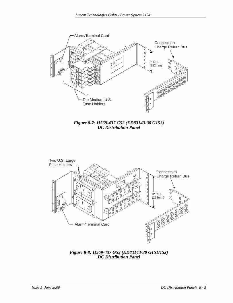
Figure 8-7: H569-437 G52 (ED83143-30 G153)DC Distribution Panel 8 - 5
Figure 8-8: H569-437 G53 (ED83143-30 G151/152)DC Distribution Panel 8 - 5
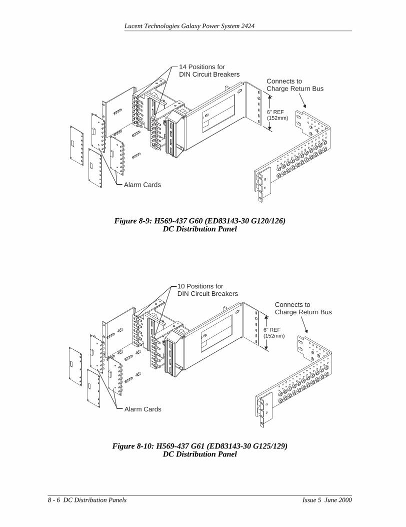
Figure 8-9: H569-437 G60 (ED83143-30 G120/126)DC Distribution Panel 8 - 6
Figure 8-10: H569-437 G61 (ED83143-30 G125/129)DC Distribution Panel 8 - 6
Figure 8-11: H569-437 G65 (ED83143-30 G124/128)DC Distribution Panel 8 - 7
Figure 8-12: H569-437 G66 (ED83143-30 G123/127)DC Distribution Panel 8 - 7
2 - List of Figures Issue 5 June 2000

Lucent Technologies Galaxy Power System 2424
9
0
12
Figure 8-13: H569-437 G67 (ED83143-30 G122)DC Distribution Panel 8 - 8
Figure 8-14: H569-437 G68 (ED83143-30 G121)DC Distribution Panel 8 - 8
Figure 9-1: Location of BLJ Terminal Board and Bay Interface Card 9 - 3
Figure 9-2: Required Straps Prior to Replacinga Bay Interface Card (BIC) 9 - 3
Figure 12-1: Detail of Rectifier Position 12 - 3
Figure 12-2: Detail of Converter Components 12 -
Figure 12-3: Cable Connection Between Two Converter Carriers 12 - 9
Figure 13-1: Location of Cabinet Alarm 13 - 2
Figure 13-2: Millennium Controller Display 13 - 7
Figure 13-3: Location of Millennium ControllerFuses and Boards 13 - 7
Figure 13-4: Vector Controller Display 13 - 8
Figure 13-5: Location of Vector ControllerFuses and Boards 13 - 8
Figure 13-6: Rectifier Display 13 - 9
Figure 13-7: Converter Status Panels 13 - 1
Figure 13-8: Low Voltage Battery Disconnect ContactorControl Switches 13 - 11
Figure 13-9: Detail of AC Input Panel and Rectifier Shelf 13 -
Figure 13-10: Detail of DC Distribution Panel 13 - 13
Figure 13-11: Low Voltage Load Disconnect ContactorControl Switches 13 - 14
Issue 5 June 2000 List of Figures - 3


Lucent Technologies Galaxy Power System 2424
- 1
3
5
7
- 10
1
2
12
8
List of Tables
Table 6-A: AC Input Panels 6 - 2
Table 10-A: Galaxy Power System 2424 Specifications 10
Table 10-B: 596B4 Rectifier Specifications 10 -
Table 10-C: Converter Specifications 10 -
Table 10-D: AC Input Panels 10 - 6
Table 10-E: Battery Connection Panels 10 -
Table 10-F: DC Distribution Panels 10 - 8
Table 12-A: GPS 2424 System Replacement Parts 12
Table 12-B: Galaxy Millennium Controller Circuit Boards 12 - 11
Table 12-C: Galaxy Vector Controller Circuit Boards and Temperature Module 12 - 1
Table 12-D: Product Documentation 12 - 1
Table 12-E: Software 12 - 12
Table 14-A: AC Alarms 14 - 3
Table 14-B: Battery Alarms 14 - 4
Table 14-C: Controller Alarms 14 - 6
Table 14-D: Distribution Alarms 14 - 11
Table 14-E: Rectifier and Converter Related Alarms 14 -
Table 14-F: Miscellaneous Alarms 14 - 1
Table 15-A: AC Alarms 15 - 3
Table 15-B: Battery Alarms 15 - 4
Table 15-C: Controller Alarms 15 - 5
Table 15-D: Distribution Alarms 15 - 6
Issue 5 June 2000 List of Tables - 1

Lucent Technologies Galaxy Power System 2424
- 7
4
Table 15-E: Rectifier and Converter Related Alarms 15
Table 15-F: Miscellaneous Alarms 15 - 1
2 - List of Tables Issue 5 June 2000

Lucent Technologies Galaxy Power System 2424
424
led, and and
ign.
tures
nd
of this
ght
1 Introduction
GPS 2424
Overview Lucent Technologies developed the Galaxy Power System (GPS) 2to support +24-volt telecommunications powering solutions in worldwide markets. The GPS 2424 combines 100-ampere, fan-cooswitchmode rectifiers, microprocessor control technologies, battery load disconnect/reconnect options, and a comprehensive line of fusecircuit breaker dc distribution options in a modular front-access desThis modularity ensures easy access, simplified installation and maintenance, and allows the system to expand in capacity and feaas power needs grow.
With 2400-ampere maximum capacity, distribution flexibility, and universal ac input capability, the GPS 2424 supports switching, transmission, and wireless applications in central office locations aenvironmentally controlled remote sites (huts or vaults).
The main emphasis of this manual is to provide a general product description that will familiarize the user with the main components the system and to provide guidelines for the basic maintenance of Galaxy Power System.
Illustrations Figures 1-1 and 1-2 illustrate the GPS 2424 half height and full heicabinets.
Issue 5 June 2000 Introduction 1 - 1

Lucent Technologies Galaxy Power System 2424
Figure 1-1: GPS 2424 Half Height Cabinet (with Battery Stand)
1 - 2 Introduction Issue 5 June 2000

Lucent Technologies Galaxy Power System 2424
Figure 1-2: GPS 2424 Full Height Cabinet
Issue 5 June 2000 Introduction 1 - 3

Lucent Technologies Galaxy Power System 2424
ms
6),
US
nt
r is 6),
so
US
ter
US
o
Customer Assistance Contacts
Customer Training Lucent Technologies offers customer training on many Power Systeproducts. For information call 1-972-284-2163. This number is answered from 8:00 a.m. until 4:30 p.m., Central Time Zone (ZoneMonday through Friday.
Customer Service For customers in the United States, Canada, Puerto Rico, and the Virgin Islands, call 1-800-THE-1PWR (1-800-843-1797). Services provided through this contact include initiating the spare parts procurement process for out of service emergencies, ordering LuceTechnologies documents, and providing other product and service information.
For other customers worldwide, call 001-972-840-0382. This numbeanswered from 8:00 a.m. until 4:30 p.m., Central Time Zone (ZoneMonday through Friday.
Technical Support Technical support for Lucent Technologies customers is available around the world during the normal product warranty period and alwhile specific contractual agreements extend this service.
For customers in the United States, Canada, Puerto Rico, and the Virgin Islands, call 1-800-CAL-RTAC (1-800-225-7822) to contact aproduct specialist to answer your technical questions and assist in troubleshooting problems.
For other customers worldwide, contact your local field support cenor your sales representative to discuss your specific needs.
Product Repair and Return
Repair and return service is provided for Lucent Technologies customers around the world.
For customers in the United States, Canada, Puerto Rico, and the Virgin Islands, call 1-800-255-1402 for information on returning of products for repair.
For other customers worldwide, contact your sales representative tdiscuss your particular circumstances.
1 - 4 Introduction Issue 5 June 2000

Lucent Technologies Galaxy Power System 2424
ger
ls”
ons an
Customer Assistance Contacts, continued
Warranty Service For domestic warranty service, contact your Warranty Service Mana(WSM). For international warranty service, contact your sales representative.
On-Line Power Systems Product Manuals
For Lucent Technologies users logging in from inside the corporatefirewall, the address of the “Power Systems On-Line Product Manuapage is http://www.cic.lucent.com/lineage.html.
For customers logging in from outside the firewall, the address is http://www.lucent8.com/lineage.html. The annual subscription fee for access to this site is $25. To obtain a password, follow the instruction-line or call 1-888-Lucent8 (1-888-582-3688). When prompted fororder number, enter or say “167-790-010.”
On-Line Power Systems Software Upgrades
EasyView software upgrades are on-line at http://www.lucent.com/networks/power/software.html.
Issue 5 June 2000 Introduction 1 - 5


Lucent Technologies Galaxy Power System 2424
in e
2 System Description
Overview
Block Diagram A basic block diagram of the Galaxy Power System 2424 is shownFigure 2-1. It illustrates the arrangement and interconnections of thsystem components from the ac input to the dc output.
Figure 2-1: Block Diagram of the GPS 2424
LVBD
LVLD
BAT BUS
CHG RTN
DISCHG RTN
LVBDControlBoard
LVLDControlBoard
Rectifiers
ChgBus(+)
ReturnBus(-)
48V DCDistribution
Battery Distribution
DC Distribution
Controller
AC Input
To 24 VoltLoads
Battery (+)
BatteryShunt
AC InputPower
Battery (-)
24VReturns
To 48 VoltLoads
Converters
COGND
Sense/ControlConnections
Issue 5 June 2000 System Description 2 - 1
Lucent Technologies Galaxy Power System 2424
l wer
tion r if
ed to ery
s to . In d
ired .
the
the
Overview, continued
System Components
The power system accepts alternating current from the commerciautility or a standby ac power source and rectifies it to produce dc pofor the using equipment. The system’s control and alarm functions interact with the rectifiers and the office. In addition, the system provides overcurrent protection and charge, discharge, and distribufacilities. Battery reserve automatically provides a source of dc powethe commercial or standby ac fails. Battery reserve can be engineersupply dc power for a specific period of time. In normal practice, battcapacity is sized to provide 3 to 8 hours of reserve time.
AC Input connects the commercial and/or standby ac power sourcethe rectifiers within the system and provides overcurrent protectionsome applications the ac service is wired directly to the rectifiers anovercurrent protection is provided at the service panel.
Rectifiers convert an ac source voltage into the dc voltage level requto charge and float the batteries and to power the using equipment
Converters transform +24Vdc power to -48Vdc power for using equipment.
Controller provides the local and remote control, monitoring, and diagnostic functions required to administer the power system.
Batteries provide energy storage for an uninterrupted power feed tousing equipment during loss of ac input or rectifier failure.
DC Distribution Panel provides overcurrent protection, connection points for the using equipment, and bus bars used to interconnect rectifiers, batteries, and dc distribution.
Battery Connection Panel provides connection points for the batterystrings through battery disconnect fuses or contactors and current monitoring shunts.
2 - 2 System Description Issue 5 June 2000

Lucent Technologies Galaxy Power System 2424
n
an
ry a
ded
ure
ll
Architecture
Configurations The GPS 2424 is available in two configurations:
• The half height cabinet, shown in Figures 1-1 and 2-2, mounts otop of a battery stand and can provide up to 800 amperes of dcpower.
• The full height (7-foot) cabinet, shown in Figures 1-2 and 2-3, cprovide up to 1200 amperes of dc power.
Each cabinet contains ac distribution, dc distribution panels, a batteconnection panel, rectifiers, termination points for load circuits, andsystem controller.
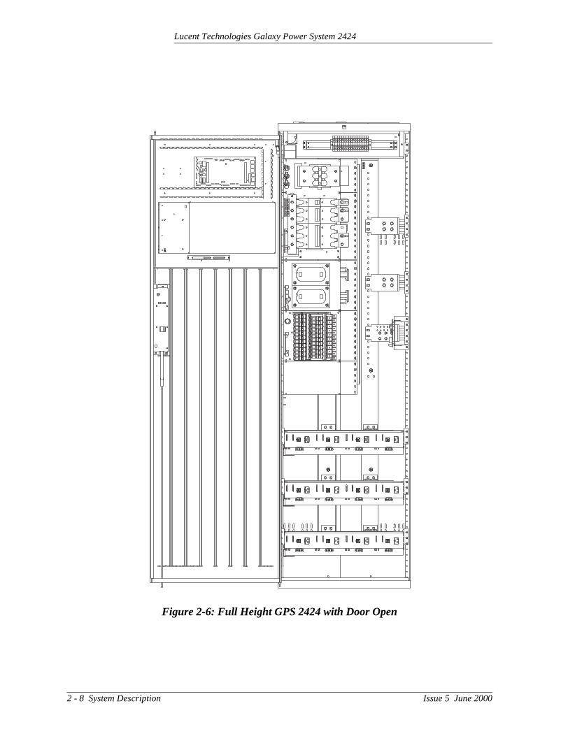
Illustrations Figure 2-4 shows how a supplemental full-height cabinet may be adto grow the system to 2400 amperes. The rectifier output buses areinterconnected to permit the two cabinets to share current and enscommon voltage references for all system rectifiers.
Figures 2-5 and 2-6 show open-door views of the half height and fuheight cabinets.
Issue 5 June 2000 System Description 2 - 3

Lucent Technologies Galaxy Power System 2424
Figure 2-2: Schematic of Half Height Cabinet
Controland
Monitor
AC
Battery String(s)Mounted Below
Half Height Cabinet
To Loads
ACGround
CabinetGround
System (CO)Ground
BatteryShunt
2 - 4 System Description Issue 5 June 2000

Lucent Technologies Galaxy Power System 2424
Figure 2-3: Schematic of Full Height Cabinet
ACGround
CabinetGround
System (CO)Ground
Controland
Monitor
BatteryString
To LoadsBatteryShunt
AC
Issue 5 June 2000 System Description 2 - 5

Lucent Technologies Galaxy Power System 2424
Figure 2-4: Schematic of Two-cabinet System Architecture
Controland
Monitor
ACInput
ACInput
BatteryString
BatteryString
Initial Cabinet Supplemental Cabinet
To LoadsTo Loads
BatteryShunt
BatteryShunt
2 - 6 System Description Issue 5 June 2000

Lucent Technologies Galaxy Power System 2424
Figure 2-5: Half Height GPS 2424 with Door Open
Issue 5 June 2000 System Description 2 - 7
Lucent Technologies Galaxy Power System 2424
Figure 2-6: Full Height GPS 2424 with Door Open
2 - 8 System Description Issue 5 June 2000

Lucent Technologies Galaxy Power System 2424
ides Ds,
3 Galaxy Controllers
Overview
Introduction The GPS 2424 is available with either the Galaxy Millennium Controller or the Galaxy Vector Controller.
This section describes the operation of each controller. It also provdetailed information about the features of their front panel keys, LEand displays.
Issue 5 June 2000 Galaxy Controllers 3 - 1

Lucent Technologies Galaxy Power System 2424
n d
bay trol
ir of
s to
tem, and e one
Galaxy Millennium Controller
Design The Galaxy Millennium Controller is equipped with a Basic control board for basic operations and an optional Intelligent control board that provides advanced local and remote monitoring and data acquisitiofeatures. These CPU control boards monitor each other’s status anissue appropriate alarms in the event a failure occurs.
Each cabinet used with the Galaxy Millennium Controller requires a interface card (BIC). The BIC acts as an interface to the cabinet conand alarm signals.
User Interface and Display
The Millennium’s primary user interface is a panel that includes a backlit LCD front panel display that can be viewed in English or Spanish, two rows of LEDs, an array of pushbutton keys, and a patest jacks. Figure 3-1 illustrates the Millennium’s front panel.
Default Display The default display shows basic system status. The controller returnthis display approximately three minutes after the last time a key ispressed. The information on the screen is updated automatically approximately every two seconds.
The default screen display is similar to the following: The first line shows the number of alarms (0) and warnings (0) present in the systhe date, and the time. The next two lines show the system voltagethe system load. The last line shows the system mode, which can bof the following:
• FLOAT• BOOST• STC (Slope Thermal Compensation)• BATT TEST
Figure 3-1: Galaxy Millennium Controller Front Panel
GALAXY MILLENNIUM CONTROLLERMenu Enter Adjust
BD
CRIT
BATT
MAJ
DIST
MIN
RECT
NORM
AC RM
COM
CTRL
LampTest
PlantVoltage
VHelp Escape
Alarms
Status
3 - 2 Galaxy Controllers Issue 5 June 2000

Lucent Technologies Galaxy Power System 2424
An han st
Galaxy Millennium Controller, continued
LEDs Two rows of LEDs show the source and severity of various alarms.alarm lights one status LED and one or more alarm LEDs. If more tone alarm LED lights, the status LED that lights will indicate the mosevere active alarm.
• The first row of seven LEDs, labeled ALARMS, indicates the source of the alarm:
BD - battery on dischargeBATT - batteryDIST - distributionRECT - rectifierAC - ac power supplyRM - remote monitoringCTRL - controller
• The second row includes four LEDs, labeled STATUS. They indicate the severity of the reported alarm:
CRIT - criticalMAJ - majorMIN - minorNORM - normal
• The COM LED illuminates when the internal modem is in use.
Test Jacks A pair of test jacks allows direct measurement of the dc bus sensevoltage being monitored by the controller.
Issue 5 June 2000 Galaxy Controllers 3 - 3

Lucent Technologies Galaxy Power System 2424
are
Galaxy Millennium Controller, continued
Pushbutton Keys A group of pushbutton keys to the right of the backlit LCD display provides the primary user interface with the controller. These keys used singly or in combination to navigate through the controller’s menus.
The following is a general description of the pushbutton keys:
• MENU: View the MAIN menu.
• ENTER: Select a menu item.
• HELP: Display limited on-line help information.
• ESCAPE: Return to the immediate higher level menu.
• Up arrow: Move the cursor up one line.
• Down arrow: Move the cursor down one line.
• Left arrow: Move the cursor left one field.
• Right arrow: Move the cursor right one field.
• ADJUST + and -: Increase or decrease parameter values.
• LAMP TEST: Test the controller’s circuit board LEDs and front panel LEDs. It will also test the indicators of serially connected rectifiers.
3 - 4 Galaxy Controllers Issue 5 June 2000

Lucent Technologies Galaxy Power System 2424
a trol t a
ys, el.
e fter
Galaxy Vector Controller
Design The Galaxy Vector Controller consists of an electronics board and terminal connection board. The Vector provides a wide range of conand monitoring features and issues appropriate alarms in the evenfailure occurs.
User Interface and Display
The Vector’s primary user interface is a panel that includes an alpha-numeric LED display, rows of LEDs, an array of pushbutton keand a pair of test jacks. Figure 3-2 illustrates the Vector’s front pan
Default Display The default display shows the system voltage. Toggle the VOLTS/AMPS switch to view system voltage or current. Press the VIEW ACTIVE ALARMS button to view the code for any active alarm. Thcontroller returns to the default display approximately 30 seconds athe last time a key is pressed.
Figure 3-2: Galaxy Vector Controller Front Panel
PLANTVOLTAGE
BATTERYTEST
THERMALCOMPENSATION
FLOAT
BOOSTVOLTS
AMPS
ESCAPE
ENTERCONFIGURE
DEFAULT
BD
MAJ
BATT
MIN
DIST
NORM
RECT
ALARMS
STATUS
CTRL
VIEW ACTIVEALARMS
AC
ACO
LAMPTEST
+ –
GALAXY VECTOR CONTROLLER
Issue 5 June 2000 Galaxy Controllers 3 - 5

Lucent Technologies Galaxy Power System 2424
hts rm
Galaxy Vector Controller, continued
LEDs LEDs show the source and severity of various alarms. An alarm ligone status LED and one or more alarm LEDs. If more than one alaLED lights, the status LED that lights will indicate the most severe active alarm.
• The ALARMS row of six LEDs indicates the source of the alarm:
– BD - battery on discharge
– BATT - battery
– DIST - distribution
– RECT - rectifier
– CTRL - controller
– AC - ac input power
• The STATUS row of three LEDs indicates the severity of the reported alarm:
– MAJ - major
– MIN - minor
– NORM - normal
• THERMAL COMPENSATION: Lights when the system voltage has been adjusted by the Thermal Compensation feature.
Test Jacks A pair of test jacks allows direct measurement of the dc bus sensevoltage being monitored by the controller.
3 - 6 Galaxy Controllers Issue 5 June 2000

Lucent Technologies Galaxy Power System 2424
y
Galaxy Vector Controller, continued
Pushbutton Keys Pushbutton keys around the backlit LCD display provide the primaruser interface with the controller. These keys are used singly or in combination to navigate through the controller’s menus.
The following is a general description of the pushbutton keys:
• VOLTS or AMPS: Select either volts or amps for viewing.
• BOOST or FLOAT: Select one of these system modes.
• BATTERY TEST: Start/stop discharge test.
• ACO: Switch between Alarm Cut Off and On. The LED lights when audible Alarm Cutoff is active.
• VIEW ACTIVE ALARMS: Display active alarms. Use the arrow keys to page through multiple alarms. The LED lights when thisoption is selected. Note: View Active Alarms and Configure cannot be active simultaneously.
• CONFIGURE: Enter Configuration Mode. The LED lights when this option is selected. Note: Configure and View Active Alarms cannot be active simultaneously.
• ENTER: Select a menu item.
• DEFAULT: In Configure mode, change a parameter to default value.
• ESCAPE: Return to the immediate higher level menu.
• Up arrow: Move the cursor up one line.
• Down arrow: Move the cursor down one line.
• Left arrow: Move the cursor left one field.
• Right arrow: Move the cursor right one field.
• ADJUST + and -: Increase or decrease parameter values.
• LAMP TEST: Test the controller’s circuit board LEDs and front panel LEDs. It will also test the indicators of serially connected rectifiers.
Issue 5 June 2000 Galaxy Controllers 3 - 7

Lucent Technologies Galaxy Power System 2424
ode
ing
Reference Material
Controller Product Manuals
Either a Galaxy Millennium Controller product manual (Select Code167-792-180) or Galaxy Vector Controller product manual (Select C167-792-112) is furnished with every GPS 2424. Refer to this manualfor information regarding configuration and operation.
RPM System Product Manual
Refer to the Galaxy Remote Peripheral Monitoring System productmanual (Select Code 167-790-063) for additional information regardmodule operation.
3 - 8 Galaxy Controllers Issue 5 June 2000
Lucent Technologies Galaxy Power System 2424
ac ac.
d
ID r’s
4 Rectifiers
596B4
Overview The 596B4 100-ampere rectifier operates from 2-wire, single-phaseservice with a phase-to-phase voltage within the range of 176-264V
The rectifiers are shipped separately from the cabinets for quick anstraightforward installation into rectifier shelves at the site. Interconnections to ac input, dc output, and control signals occur automatically during insertion. The rectifier is keyed to prevent installation of the wrong rectifier. No settings or adjustments to potentiometers are necessary. The installer must set the rectifier’s using the ON/STBY switch to allow the controller to learn the rectifiephysical location.
The 596B4 rectifier is UL Recognized for both the U. S. and Canada,complies with UL1950 (Information Technology Equipment), and meets EN60950 requirements.
Issue 5 June 2000 Rectifiers 4 - 1

Lucent Technologies Galaxy Power System 2424
.
tton
Front Panel Display
Power Switch This three-position switch has two active states:
• It controls the on/standby state of the rectifier.
• It is used to set the rectifier ID.
Status Indicators In addition to the ON and STBY LEDs, four other LEDs on the rectifier’s faceplate indicate the rectifier’s condition.
• The ALM LED is red and lights whenever the rectifier fails.
• The LIM LED is yellow and lights when the unit is in current limit
• The FAN ALM LED is red and lights when the fan inside the rectifier is not functioning properly.
• The BST LED is yellow and lights when the rectifier is in boost mode.
Current Display This display indicates the current of the rectifier. Upon specific no-power conditions, the 3-digit display will show informative messages.
Lamp Test To test the LEDs on the rectifier front panel, press the Lamp Test buon the controller.
4 - 2 Rectifiers Issue 5 June 2000

Lucent Technologies Galaxy Power System 2424
Front Panel Display, continued
Illustration Figure 4-1 shows the rectifier’s front panel.
Figure 4-1: Rectifier Front Panel
ID
ALM
ON
STBY LIM FANALM
BST
Issue 5 June 2000 Rectifiers 4 - 3

Lucent Technologies Galaxy Power System 2424
his e.
if a
et nd ge
e is
l tart. fier
d on oad
e a evel.
Features
Output Current “Walk-in”
This circuit controls the time (up to eight seconds) required for the rectifier to reach normal operating conditions after it is turned on. Tfeature minimizes the starting surge on the customer's power sourc
Output Protection The rectifier is equipped with an internal fuse for system protection fault occurs in a rectifier.
Electronic Current Limit
When the output current tends to increase above the current limit spoint, the current limit circuit overrides the voltage regulating signal asafely limits the output current of the rectifier, thus preventing damato itself or the load.
High Voltage Shutdown (HVSD)
The rectifier senses the voltage at its output terminals. If this voltagtoo high, the rectifier will shut down to prevent the high voltage fromdamaging itself or the load.
Restart Upon shutdown, the rectifier will attempt to restart. The rectifier wilalso accept a restart command from the controller for a remote resThe rectifier will attempt to restart three times before issuing a rectifail alarm to the controller.
Fan Alarm and Control
The rectifier contains a cooling fan. The fan’s speed, which is baseambient temperature and output power level, is lowered during low-land low-temperature conditions to minimize audible noise and maximize fan life.
Thermal Alarm The rectifier senses the internal operating temperature and will issuthermal alarm if the internal temperature exceeds a safe operating lAmbient temperatures above the maximum rating will result in a rectifier shutdown and the issuing of a thermal alarm (TA).
Autonomous Operation
Rectifiers will continue to power the load if the controller fails or if communication is lost.
Controller Communications Alarm
When communications between the rectifier and controller are interrupted, the rectifier continues to operate and the red ALM LED on the rectifier blinks.
4 - 4 Rectifiers Issue 5 June 2000

Lucent Technologies Galaxy Power System 2424
nd dc the
Features, continued
Connectorized The rectifiers provide the controller with a full complement of status aalarm signals. The rectifier status and alarm signals, ac input, and output are all connectorized for easy installation and maintenance.System connections are made when the rectifiers are plugged intoshelf. No additional connections are required.
“Forced” Load Sharing
Internal rectifier circuitry will allow multiple rectifiers to share load inthe event communication to the controller is lost or the controller malfunctions.
Issue 5 June 2000 Rectifiers 4 - 5


Lucent Technologies Galaxy Power System 2424
e es
the
5 Converters
597A and 597B
Overview The converter carriers and modules are shipped separately from thcabinets for quick and straightforward installation into rectifier shelvat the site. Interconnections to dc output and control signals occur automatically during insertion. No settings or adjustments to potentiometers are necessary.
The 597A and 597B converter carriers are UL Recognized for bothU. S. and Canada, comply with UL 1950 (Information Technology Equipment), and meet EN60950 requirements.
Output Distribution
• The 597A converter carrier provides four positions for DIN-stylecircuit breakers and slots for four 24V/48Vdc, 3-ampere 47A converter modules.
• The 597B converter carrier provides six positions for GMT-typefuses and slots for four 24V/48Vdc, 3-ampere 47A converter modules.
• One 128A Converter Interface Card (CIC) is required for each converter carrier.
Issue 5 June 2000 Converters 5 - 1

Lucent Technologies Galaxy Power System 2424
to is
has
a
n
Displays
Current and Voltage
A switch allows a pair of test jacks on the Converter Interface Cardsense either the current or voltage. In the current setting, the scale3.95mV/A.
128A Converter Interface Card LEDs
The main status panel on the 128A Converter Interface Card (CIC)three LEDS:
• The ON LED is green and lights under normal operation.
• The CFA LED is red and lights when a converter module is off ormodule fan has failed.
• The FA LED is red and lights when a distribution fuse or circuit breaker has operated.
47A Converter Module LEDs
Each 47A converter module has its own set of LEDs:
• The green ON LED lights under normal operation.
• The yellow STBY LED lights when a converter module has beenturned off.
• The red ALM LED lights when a converter module has failed.
597A and 597B Converter Carrier LEDs
The converter carrier has NORMAL (green) and ALARM (red) LEDs. When the ALM LED of a converter module lights, the ALARM LED othe carrier also lights.
5 - 2 Converters Issue 5 June 2000

Lucent Technologies Galaxy Power System 2424
ls.
Displays, continued
Illustration Figure 5-1 illustrates the converter carrier and converter front pane
Figure 5-1: Carrier and Converter Front Panels
NORMAL
ALARM
ONOn/Standby Switch
STBYALM
ONCFA
FA
Converter Carrier
128A CIC
Converter Interface Cardand Converter Modules
47A Converter Modules
Issue 5 June 2000 Converters 5 - 3


Lucent Technologies Galaxy Power System 2424
vice lies
n ads
ctor
s are nel.
6 AC Input Panels
Overview
AC Service The ac input panel provides the facility to terminate 3-phase ac serto the GPS 2424 system or to distribute individual 1-phase ac suppto each of the system rectifier positions. Depending upon the optioordered, the panel will connect 3-wire (three phases), 4-wire (threephases + neutral), or individual 2-wire (single phase, either 2 hot leor 1 hot lead and neutral) input ac service.
In some systems circuit breakers are provided to protect the conduproviding ac service to the individual rectifiers. In other systems thesystem’s ac input panel contains a terminal strip and the conductorprotected by circuit breakers located in the building’s ac service pa
Note: All wire sizes were based on the US National Electric Code.
Issue 5 June 2000 AC Input Panels 6 - 1

Lucent Technologies Galaxy Power System 2424
trip
Overview, continued
Cross Reference of Cabinets and Panels
Table 6-A identifies which cabinet uses each of the panels.
Illustrations Circuit breaker panels are shown in Figures 6-1 and 6-2; terminal spanels are shown in Figures 6-3 and 6-4.
Table 6-A: AC Input Panels
Panel Cabinet FigureH569-437 G73F(ED83142-30 G6)
Full-height cabinet with two shelves of rectifiers that are connected phase to phase
Figure 6-1
H569-437 G71H(ED83142-30 G6)
Half-height cabinet with two shelves of rectifiers that are connected phase to phase
Figure 6-1
H569-437 G74F(ED83142-30 G6M)
Full-height cabinet with two shelves of rectifiers that are connected phase to neutral
Figure 6-1
H569-437 G74H(ED83142-30 G6M)
Half-height cabinet with two shelves of rectifiers that are connected phase to neutral
Figure 6-1
H569-437 G72F(ED83142-30 G7)
Full-height cabinet with three shelves of rectifiers that are connected phase to phase
Figure 6-2
H569-437 G76H(ED83142-30 G8)
Half-height cabinet with two shelves of rectifiers that are connected phase to phase or phase to neutral
Figure 6-3
H569-437 G77F(ED83142-30 G9)
Full-height cabinet with three shelves of rectifiers that are connected phase to phase or phase to neutral
Figure 6-4
6 - 2 AC Input Panels Issue 5 June 2000

Lucent Technologies Galaxy Power System 2424
Figure 6-1: H569-437 G73F/71H (ED83142-30 G6)H569-437 G74F/74H (ED83142-30 G6M)
AC Input Circuit Breaker Panel
Figure 6-2: H569-437 G72F (ED83142-30 G7)AC Input Circuit Breaker Panel
Issue 5 June 2000 AC Input Panels 6 - 3

Lucent Technologies Galaxy Power System 2424
Figure 6-3: H569-437 G76H (ED83142-30 G8)AC Input Terminal Strip Panel
Figure 6-4: H569-437 G77F (ED83142-30 G9)AC Input Terminal Strip Panel
6 - 4 AC Input Panels Issue 5 June 2000

Lucent Technologies Galaxy Power System 2424
ction
tus e
trol
ets
7 Battery Connection Panels
Overview
Function Batteries are connected to the GPS 2424 cabinets on battery connepanels located in the cabinet directly below or behind the ac input panel. All panels include the battery shunts and an alarm card that communicates with the controller to provide battery current and stainformation. As options, the panels may include fuses or low voltagbattery disconnect/reconnect (LVBD/R) contactors. When equippedwith contactors, a contactor control card provides local/manual conof the contactors.
Note: If no battery panel is needed (for full height supplemental cabinonly), H569-437 G33F is selected as a placeholder in the order.
Illustrations These panels are shown in Figures 7-1 through 7-8.
Note: Battery connection panels are blue; dc distribution panels arewhite.
Issue 5 June 2000 Battery Connection Panels 7 - 1

Lucent Technologies Galaxy Power System 2424
Figure 7-1: H569-437 G30 (ED83143-30 G132)Battery Connection Panel
Two 500A Contactors
Contactor Control Cards
Two 1000A Shunts
Connects toCharge Return Bus
9" REF(229mm)
Figure 7-2: H569-437 G31 (ED83143-30 G131)Battery Connection Panel
Contactor Control Card
1200A Contactor 1500A Shunt
Connects toCharge Return Bus
6" REF(152mm)
7 - 2 Battery Connection Panels Issue 5 June 2000

Lucent Technologies Galaxy Power System 2424
Figure 7-3: H569-437 G34 (ED83143-30 G141)Battery Connection Panel
Terminal Card
Alarm Card
(2) NH3 Fuse Holders
Connects toCharge Return Bus
9" REF(229mm)
Two 600A Shunts
Figure 7-4: H569-437 G35 (ED83143-30 G142)Battery Connection Panel
Alarm/TerminalCard
(1) NH3 Fuse Holder
Connects toCharge Return Bus
6" REF(152mm)
600A Shunt
Issue 5 June 2000 Battery Connection Panels 7 - 3

Lucent Technologies Galaxy Power System 2424
Figure 7-5: H569-437 G36H (ED83143-30 G133)Battery Connection Panel
1000A Shunt
800A Contactor
Contactor Control Card
Figure 7-6: H569-437 G80/81/82 (ED83143-30 G131/143)Battery Connection Panel
Contactor Control Card
AlarmCards
1200A ContactorH569-437 G131
1200A Contactor
H569-437 G143*Two NH3 DIN FusesTwo 600A Shunts
Connect toCharge Return Bus
Connect toCharge Return Bus
G80
G81
G82
1 G1311 G1431 G1312 G1431 G1313 G143 (shown)
*H569-437 Battery Module
Includes:Group #
24" REF(610mm)
7 - 4 Battery Connection Panels Issue 5 June 2000

Lucent Technologies Galaxy Power System 2424
Figure 7-7: H569-437 G84H (ED83143-30 G134)Battery Connection Panel
1000A Shunt
Figure 7-8: H569-437 G85F (ED83143-30 G135)Battery Connection Panel
1500A Shunt
Issue 5 June 2000 Battery Connection Panels 7 - 5


Lucent Technologies Galaxy Power System 2424
em, with LED
4.
re
8 DC Distribution Panels
Overview
Function A variety of dc distribution panels is available for the GPS 2424 systincluding DIN standard fuse holders and circuit breakers and U. S.standard fuse holders and circuit breakers. All panels are equippedan alarm card. When a fuse operates or a circuit breaker trips, a redon the alarm card lights, the cabinet alarm lights, and the alarm is transmitted to the controller. Most panels are also available with contactors to provide low voltage load disconnect.
Illustrations The dc distribution panels are illustrated in Figures 8-1 through 8-1
Note: DC distribution panels are white; battery connection panels ablue.
Issue 5 June 2000 DC Distribution Panels 8 - 1

Lucent Technologies Galaxy Power System 2424
Figure 8-1: H569-437 G40/50 (ED83143-30 G111/113)DC Distribution Panel
Alarm/Terminal Card
13 Positions for U.S.Plug-in Circuit Breakersor Fuse Holders
Connects toCharge Return Bus
6" REF(152mm)
Figure 8-2: H569-437 G41/51 (ED83143-30 G112/114)DC Distribution Panel
Alarm/Terminal Card
21 Positions for U.S.Plug-in Circuit Breakersor Fuse Holders
Connects toCharge Return Bus
9" REF(229mm)
8 - 2 DC Distribution Panels Issue 5 June 2000

Lucent Technologies Galaxy Power System 2424
Figure 8-3: H569-437 G42 (ED83143-30 G102/103)DC Distribution Panel
Alarm/Terminal Card
Three Positions for LargeU.S. Circuit Breakers
Connects toCharge Return Bus
6" REF(152mm)
Figure 8-4: H569-437 G43 (ED83143-30 G101/104)DC Distribution Panel
Alarm Card
Terminal CardSix Positions for LargeU.S. Circuit Breakers
Connects toCharge Return Bus
12" REF(305mm)
Issue 5 June 2000 DC Distribution Panels 8 - 3

Lucent Technologies Galaxy Power System 2424
Figure 8-5: H569-437 G44 (ED83143-30 G105/106)DC Distribution Panel
Alarm Card
Five Positions for LargeU.S. Circuit Breakers Connects to
Charge Return Bus
Terminal Card
9" REF(229mm)
Figure 8-6: H569-437 G45 (ED83143-30 G115/116)DC Distribution Panel
Alarm/Terminal Card
10 Positions for Plug-in(Bullet Style) Circuit Breakers
Connects toCharge Return Bus
6" REF(152mm)
8 - 4 DC Distribution Panels Issue 5 June 2000
Lucent Technologies Galaxy Power System 2424
Figure 8-7: H569-437 G52 (ED83143-30 G153)DC Distribution Panel
Alarm/Terminal Card
Connects toCharge Return Bus
Ten Medium U.S.Fuse Holders
6" REF(152mm)
Figure 8-8: H569-437 G53 (ED83143-30 G151/152)DC Distribution Panel
Connects toCharge Return Bus
Two U.S. LargeFuse Holders
Alarm/Terminal Card
9" REF(229mm)
Issue 5 June 2000 DC Distribution Panels 8 - 5
Lucent Technologies Galaxy Power System 2424
Figure 8-9: H569-437 G60 (ED83143-30 G120/126)DC Distribution Panel
Alarm Cards
14 Positions forDIN Circuit Breakers
Connects toCharge Return Bus
6" REF(152mm)
Figure 8-10: H569-437 G61 (ED83143-30 G125/129)DC Distribution Panel
Alarm Cards
10 Positions forDIN Circuit Breakers
Connects toCharge Return Bus
6" REF(152mm)
8 - 6 DC Distribution Panels Issue 5 June 2000

Lucent Technologies Galaxy Power System 2424
Figure 8-11: H569-437 G65 (ED83143-30 G124/128)DC Distribution Panel
Alarm Cards
14 DIN Fuse Holders
Connects toCharge Return Bus
6" REF(152mm)
Figure 8-12: H569-437 G66 (ED83143-30 G123/127)DC Distribution Panel
Alarm Cards
10 DIN Fuse Holders
Connects toCharge Return Bus
6" REF(152mm)
Issue 5 June 2000 DC Distribution Panels 8 - 7

Lucent Technologies Galaxy Power System 2424
Figure 8-13: H569-437 G67 (ED83143-30 G122)DC Distribution Panel
Alarm/Terminal Card
Eight NH00 Fuse Holders
Connects toCharge Return Bus
6" REF(152mm)
Figure 8-14: H569-437 G68 (ED83143-30 G121)DC Distribution Panel
Alarm/Terminal Card Connects toCharge Return Bus
Two NH2 Fuse Holders
6" REF(152mm)
8 - 8 DC Distribution Panels Issue 5 June 2000

Lucent Technologies Galaxy Power System 2424
e d by
ller, e ttery nels
9 Circuit Boards
Overview
Function Circuit boards (sometimes referred to as “cards”) are included in thbattery connection and dc distribution panels to provide data requirethe controller.
Terminal Boards Terminal boards are used to provide shunt voltage data to the controwhere it is used to calculate current. Terminal boards located on thbattery connection panels provide data that is used to calculate bacurrent; data from terminal boards located on the dc distribution pais used to calculate load current.
Alarm Boards Alarm boards perform two functions:
• monitor panel functions and activate local indicators when faultsoccur on the panel
• provide alarm data to the controller
Alarm/Terminal Boards
Alarm/terminal boards combine the functions of alarm boards and terminal boards.
Issue 5 June 2000 Circuit Boards 9 - 1

Lucent Technologies Galaxy Power System 2424
ns BLJ
BIC es nts,
us.
a ntal
BLJ Terminal Board
Millennium Systems
A BLJ terminal board is located inside the door of each initial and supplemental cabinet of a Millennium system. The BLJ is the termination point for distribution alarms in each cabinet. It uses therectifier serial bus to communicate with the controller.
Vector Systems The Vector controller, which is installed in the initial cabinet, contaia BLJ terminal connection board. This board is daisy-chained to a board in each supplemental cabinet.
Bay Interface Card
Millennium Systems
Each initial and supplemental cabinet in a Millennium system has a that attaches to the cabinet’s terminal board (BLJ). The BIC providcontroller access to alarm monitoring, battery voltages, battery curreand temperature probes in the cabinet through the serial rectifier b
Vector Systems The initial cabinet contains the Vector controller, which consists of BIC2 control board and a BLJ terminal connection board. Supplemecabinets do not require a BIC.
9 - 2 Circuit Boards Issue 5 June 2000

Lucent Technologies Galaxy Power System 2424
ace to
Illustrations
BLJ and BIC Locations
Figure 9-1 shows the location of the BLJ terminal board and Bay Interface Card (BIC).
Replacing a BIC Figure 9-2 shows the straps required prior to replacing a Bay InterfCard (BIC). (See “BIC Failure” in Table 14-C.) Straps are backups ensure continous operation of LVBD and LVLD contactors.
Figure 9-1: Location of BLJ Terminal Board and Bay Interface Card
BLJ BIC
Figure 9-2: Required Straps Prior to Replacinga Bay Interface Card (BIC)
BLJ2/3
Straps For Replacing BIC Board
Issue 5 June 2000 Circuit Boards 9 - 3

Lucent Technologies Galaxy Power System 2424
10 Specifications
GPS 2424
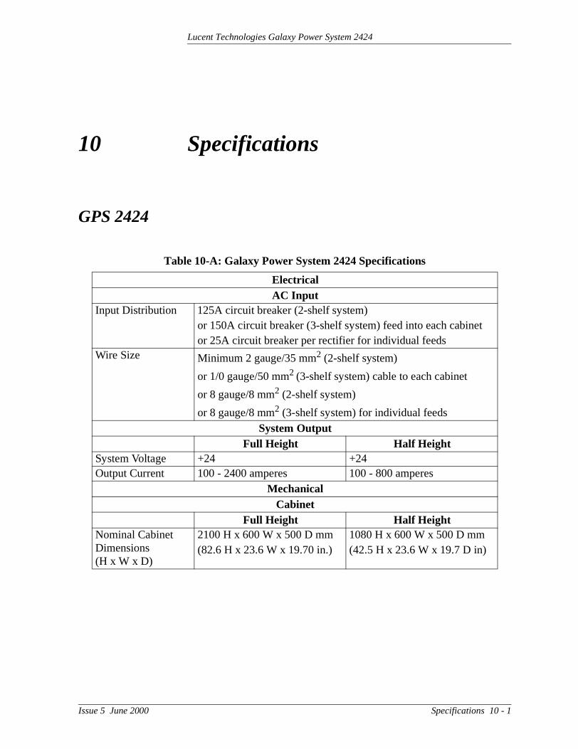
Table 10-A: Galaxy Power System 2424 Specifications
ElectricalAC Input
Input Distribution 125A circuit breaker (2-shelf system)or 150A circuit breaker (3-shelf system) feed into each cabinet or 25A circuit breaker per rectifier for individual feeds
Wire Size Minimum 2 gauge/35 mm2 (2-shelf system)
or 1/0 gauge/50 mm2 (3-shelf system) cable to each cabinet
or 8 gauge/8 mm2 (2-shelf system)
or 8 gauge/8 mm2 (3-shelf system) for individual feedsSystem Output
Full Height Half HeightSystem Voltage +24 +24Output Current 100 - 2400 amperes 100 - 800 amperes
MechanicalCabinet
Full Height Half HeightNominal Cabinet Dimensions (H x W x D)
2100 H x 600 W x 500 D mm(82.6 H x 23.6 W x 19.70 in.)
1080 H x 600 W x 500 D mm(42.5 H x 23.6 W x 19.7 D in)
Issue 5 June 2000 Specifications 10 - 1

Lucent Technologies Galaxy Power System 2424
Units Per Initial CabinetFull Height Half Height
Rectifiers 1 - 12 1 - 8Controller 1 Battery Disconnect Modules
0 - 1
DC Distribution 1 - 6 1 - 3Units Per Supplemental Cabinet
Rectifiers 0 - 12 N/ABattery Disconnect Modules
0 - 1 N/A
DC Distribution 1 - 6 N/AEnvironmental
Operating Ambient Temperature
0°C to 45°C
Altitude -50 to 4000 meters Note: For altitudes between 1500 and 4000 meters, derate the maximum temperature by 0.656°C per 100 meters.
Humidity 5% to 90% non-condensingRadiated and Conducted Emissions
EN50082-1, EN50082-2, EN50081, EN61000
Electromagnetic Immunity
Level B
Earthquake Rating Zone 4, upper floorsStandards Compliance
Agency Approvals • CE Marked, UL
• Underwriters Laboratories (UL) Listed per Subject Letter 1801, DC Power Distribution Centers for Telecommunications Equipment
Table 10-A: Galaxy Power System 2424 Specifications
10 - 2 Specifications Issue 5 June 2000

Lucent Technologies Galaxy Power System 2424
ps s
Rectifier
Table 10-B: 596B4 Rectifier Specifications
ElectricalInput
Voltage Range 176-264Vac, 2-wire, single phaseFrequency Range 47 - 63 HzPower Factor > 0.98 for loads > 50%High Voltage ShutdownInternal Selective High Voltage Shutdown (ISHVSD)
Backup High Voltage Shutdown3 (BUHVSD)
596B4 Float 28.75V1 Nom.2
596B4 Boost 28.75V1 Nom.2
596B4 Boost/Float 29.76Vdc Nom.
1Selectable/programmable through Galaxy Controller2Factory default setting – actual range is 22 - 30Vdc3Hardwired feature in rectifier – range is 29.275 - 30.265VdcRated Service Entrance Surge Protector: It is important that the service entrance surge protector (if provided) be coordinated with the internal surge protection and that it clamat a lower voltage then the internal protection. The internal protection of the 596B4 hathe following voltage and current characteristics:
Phase to Phase Voltage MOV Conduction Current320Vac (RMS) 0A565Vpeak maximum clamping 1mA (DC test current)850Vpeak 100A peak (8 x 20µs)
OutputOutput Current 100 amperesFloat/Boost Voltage 22-29VdcTotal Harmonic Distortion 10% at Nom. Line VRegulation ±0.5%Ripple 100 mVrmsNoise < 1mV psophometricPermanent Overload 110ACurrent Limit Set Point 15A-110A
Note: When using the maximum 12 rectifiers in a cabinet, do not exceed 100 amperes current limit per rectifier at 50°C.
Issue 5 June 2000 Specifications 10 - 3

Lucent Technologies Galaxy Power System 2424
MechanicalWidth 5.25 in. (133.35 mm)Height 8 in. (203.2 mm)Depth 19.75 in. (501.65 mm)Weight 20 lbs. (9 kg)
EnvironmentalEfficiency > 86% typicalOperating Temperature -40°C to 65°C (rectifier only)Operating Relative Humidity 5% to 90%Heat Release24Vdc, 100A Output24Vdc, 80A Output
Per Rectifier:390 Watts (1331.3 BTU/hr.)312 Watts (1065 BTU/hr.)
Short Term Operating Relative Humidity 5% to 90%Storage Temperature -45°C to 85°CStorage Relative Humidity 5% to 90%Altitude -50 to 4000 meters
Note: For altitudes above 1500 meters, deratethe temperature by 0.656° Celsius per 100 meters.
Audible Noise < 52dBAEMC EN 50022, level B, conducted and radiated
(CISPR 22)Standards Compliance
Safety Standard EN 60950 (IEC950)Certification Marks UL, TUV, CE
Rectifiers are individually UL Recognized and/or CSA Certified to UL1950 and CSA C22.2 No 234/950. Rectifiers are also approved to IEC-950/EN60950 by an EC Notified Body and have outputs classified as SELV.
Table 10-B: 596B4 Rectifier Specifications
10 - 4 Specifications Issue 5 June 2000

Lucent Technologies Galaxy Power System 2424
Converters
Table 10-C: Converter Specifications
Electrical and ThermalNominal Input Voltage 24VInput Voltage Range 18V - 31VNominal Input Current 7.2A per 47A converter;
28.9A (full 597A/B)Efficiency System (597A/B) 46A
88%91%
Regulation ±1.0%Ripple 10mVrms; 100mVp-pOutput Noise 32 DBrncLoad Share Accuracy 5% of the total currentNominal Output Voltage 52VOutput Voltage Range 46.0V - 57.0VOutput Current 0-12A per converter carrier
0-24A two carriers in parallel0-36A three separate converter carriers (full height GPS 2424)
EnvironmentalTemperature 0°C-50°CHeat Dissipation 47A 597A/B
21W with 72BTU/hour typical84W with 288 BTU/hour typicalwith four 47A converters
Humidity 5%-95%Audible Noise 60 dBA
Safety/Standards ComplianceSafety Agency Approvals UL, VDEEMI CISPR Class B, EMI FCC Level B
Issue 5 June 2000 Specifications 10 - 5

Lucent Technologies Galaxy Power System 2424
AC Input Panels
Table 10-D: AC Input Panels
DescriptionH569-437 Group No.
ED83142-30 Group No.
AC Input Circuit Breaker PanelFull-height cabinet with two shelves of rectifiers that are connected phase to phase
G73F G6
AC Input Circuit Breaker PanelHalf-height cabinet with two shelves of rectifiers that are connected phase to phase
G71H G6
AC Input Circuit Breaker PanelFull-height cabinet with two shelves of rectifiers that are connected phase to neutral
G74F G6M
AC Input Circuit Breaker PanelHalf-height cabinet with two shelves of rectifiers that are connected phase to neutral
G74H G6M
AC Input Circuit Breaker PanelFull-height cabinet with three shelves of rectifiers that are connected phase to phase
G72F G7
AC Input Terminal Strip PanelHalf-height cabinet with two shelves of rectifiers that are connected phase to phase or phase to neutral
G76H G8
AC Input Terminal Strip PanelFull-height cabinet with three shelves of rectifiers that are connected phase to phase or phase to neutral
G77F G9
10 - 6 Specifications Issue 5 June 2000

Lucent Technologies Galaxy Power System 2424
Battery Connection Panels
Table 10-E: Battery Connection Panels
DescriptionH569-437 Group No.
ED83143-30Group No.
LVBD: (2) 500A contactors with 1000A shunts
G30 G132
LVBD: 1200A contactor with 1500A shunt
G31 G131
Fuse holder for 315-630A NH3 DIN fuse with 600A shunt
G35 G142
LVBD: 800A contactor with 1000A shunt
G36H G133
(2) fuse holders for 315-630A NH3 DIN fuses with 600A shunts
G34 G141
LVBD: 1200A contactor, (2) NH3 DIN fuses and (2) 600A shunts G80
G131 (1)G143 (1)
LVBD: 1200A contactor, (4) NH3 DIN fuses and (4) 600A shunts G81
G131 (1)G143 (2)
LVBD: 1200A contactor, (6) NH3 DIN fuses and (6) 600A shunts G82
G131 (1)G143 (3)
1000A shunt G84H G1341500A shunt G85F G135
Issue 5 June 2000 Specifications 10 - 7

Lucent Technologies Galaxy Power System 2424
DC Distribution Panels
Table 10-F: DC Distribution Panels
DescriptionH569-437 Group No.
ED83143-30 Group No.
13 positions for 0-100A plug-in fuse holders or circuit breakers
G40, G50 G111, G113
21 positions for 0-100A plug-in fuse holders or circuit breakers
G41, G51 G112, G114
3 positions for 125-600A circuit breakers
G42 G102, G103
6 positions for 125-600A circuit breakers
G43 G101, G104
5 positions for 125-600A circuit breakers
G44 G105, G106
10 positions for 0-150A plug-in (bullet style) circuit breakers
G45 G115, G116
10 fuse holders for 1-60A fuses G52 G1532 fuse holders for 100-600A fuses G53 G151, G15214 positions for 1-63A DIN circuit breakers
G60 G120, G126
10 positions for 80-125A DIN circuit breakers
G61 G125, G129
14 fuse holders for 1-32A DIN fuses G65 G124, G12810 fuse holders for 1-50A DIN fuses G66 G123, G1278 fuse holders for 4-160A DIN NH00 fuses
G67 G122
2 fuse holders for 32-400A DIN NH2 fuses
G68 G121
10 - 8 Specifications Issue 5 June 2000

Lucent Technologies Galaxy Power System 2424
Issue 5 June 2000 Safety 11 - 1
11 Safety
Please read and follow all safety instructions and warnings before servicing the Galaxy Power System. Reference the GPS Installation Guide and individual module product manuals for additional safety statements specific to the modules.


Lucent Technologies Galaxy Power System 2424
the be ty in
12 Maintenance and Replacement
Requirements
System With the exception of the batteries, periodic maintenance specific topower system is not required. The ac service for the building must maintained with ANSI specified limits. The temperature and humidiwithin the power room must be maintained within the limits specifiedSection 10 of this product manual.
Batteries The batteries must be maintained as directed by the battery manufacturer’s requirements.
Rectifiers With the exception of a fan failure, rectifiers are repaired by replacement. Refer to “Installing or Replacing a Rectifier” in this section.
Issue 5 June 2000 Maintenance and Replacement 12 - 1

Lucent Technologies Galaxy Power System 2424
ly
e
.
ity, is
e be
te as g a
) is d in
ch is his larm te
nce e time. te as ent
Requirements, continued
Rectifier Fan Assembly
The expected life of the rectifier fans at 25°C (77°F) is approximateeight years. The fans in the rectifiers may be replaced in the field.
Two approaches can be taken to fan maintenance:
• The first approach is to replace the fan on a routine basis everyseven to eight years; this ensures that the fan does not fail in thfield under normal operating conditions. This approach is appropriate when there are no remote alarm facilities at the site
• The second approach, assuming one has remote alarm capabilto wait until the fan fails. The rectifier will safely shut down and issue both a fail alarm and a thermal alarm. The fan can then breplaced. Since it is likely that all the rectifiers in that installationare of roughly the same age, all rectifier fans at that site shouldreplaced at that time.
The approach used depends on the location and manning of the siwell as the monitoring of alarms used at the site. Refer to “ReplacinRectifier Fan Assembly” in this section.
Converters With the exception of a fan failure, converters are repaired by replacement.The expected life of the converter fans at 25°C (77°Fapproximately five years. The fans in the converters may be replacethe field.
Two approaches can be taken to fan maintenance. The first approato replace the two fans on a routine basis every four to five years; tensures that the fans do not fail in the field under normal operatingconditions. This approach is appropriate when there are no remote afacilities at the site. The second approach, assuming one has remoalarm capability, is to wait until a fan fails. It can then be replaced. Siit is likely that all the converters in that installation are of roughly thsame age, all converter fans at that site should be replaced at that The approach used depends on the location and manning of the siwell as the monitoring of alarms used at the site. The fan replacemprocedure is described in this section.
12 - 2 Maintenance and Replacement Issue 5 June 2000

Lucent Technologies Galaxy Power System 2424
Replacement Procedures
Installing or Replacing a Rectifier
Installing or Replacing a Rectifier
Step Action
1 Locate and turn off the ac service feeding the rectifier.Note: Do not turn off ac service to the entire system, only tothe rectifier that has failed.
2 Turn the rectifier’s ON/STBY switch to STBY.
CautionRear portion of the rectifier or converter that is in operation is HOT to the touch. Use appropriate precautions.
3 (Steps 3 and 4 for replacement only. For a new installation,proceed to Step 5.)
Locate the Allen-head bolt in the center of the rectifier frontpanel. Using the Allen wrench provided, rotate the bolt counterclockwise to release the rectifier for removal.
4Caution
Handle the rectifier or converter using two hands, one hand supporting the rear of the unit, the other hand on the front handle.
Grasp the front handle and slide/pull the rectifier from the shelf assembly. Support the rear of the unit as it slides fromthe shelf.
Figure 12-1: Detail of Rectifier Position
Continued on next page.
Issue 5 June 2000 Maintenance and Replacement 12 - 3

Lucent Technologies Galaxy Power System 2424
e
Replacement Procedures, continued
!
Installing or Replacing a Rectifier, continued
Step Action
5 Slowly slide new rectifier onto the shelf until it contacts therear connector.
6 Using the Allen wrench, turn the Allen-head bolt clockwiseto pull the rectifier into the shelf.
7 Once the rectifier has been installed, set the rectifier ID.Follow the directions for the “ID Not Configured” alarm in Table 14-E (Millennium) or “rid” in Table 15-E (Vector).
Note: The red LED on the rectifier will blink until the rectifier establishes communication with the controller. After communication is established, the controller will issua RECT MAJ alarm until the rectifier ID is set.
8 Turn the ac service back on.
9 Turn the rectifier’s ON/STBY switch to ON.
12 - 4 Maintenance and Replacement Issue 5 June 2000
Lucent Technologies Galaxy Power System 2424
in
,
d
the
Replacement Procedures, continued
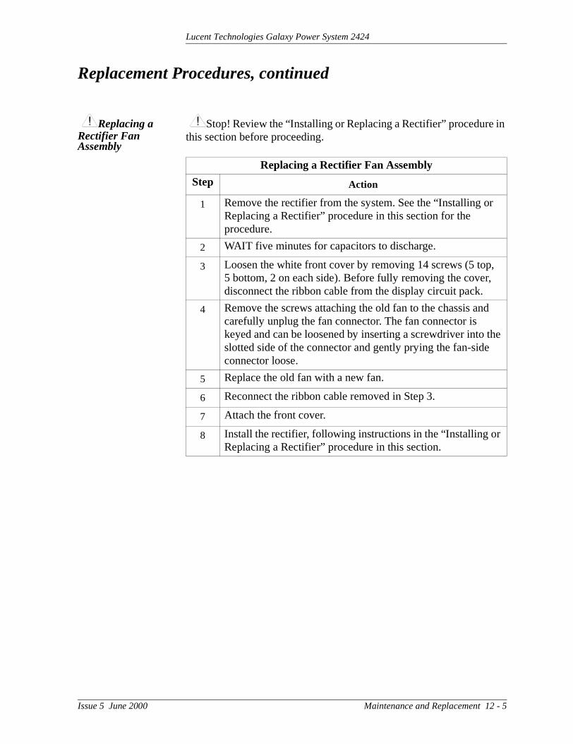
Replacing a Rectifier Fan Assembly
Stop! Review the “Installing or Replacing a Rectifier” procedurethis section before proceeding.
Replacing a Rectifier Fan Assembly
Step Action
1 Remove the rectifier from the system. See the “Installing orReplacing a Rectifier” procedure in this section for the procedure.
2 WAIT five minutes for capacitors to discharge.
3 Loosen the white front cover by removing 14 screws (5 top5 bottom, 2 on each side). Before fully removing the cover,disconnect the ribbon cable from the display circuit pack.
4 Remove the screws attaching the old fan to the chassis ancarefully unplug the fan connector. The fan connector is keyed and can be loosened by inserting a screwdriver into slotted side of the connector and gently prying the fan-sideconnector loose.
5 Replace the old fan with a new fan.
6 Reconnect the ribbon cable removed in Step 3.
7 Attach the front cover.
8 Install the rectifier, following instructions in the “Installing or Replacing a Rectifier” procedure in this section.
Issue 5 June 2000 Maintenance and Replacement 12 - 5

Lucent Technologies Galaxy Power System 2424
en
d.
lf.
Replacement Procedures, continued
Replacing a Converter Carrier
Note: This procedure will disconnect the 48V output from the load evif two carriers are being used.
Replacing a Converter Carrier
Step Action
1 Open the carrier door.
2 Remove all converter modules from the carrier to be replaceSee “Replacing a Converter Module.”
3 Locate the Allen-head retaining screw. See Figure 12-2. Using the Allen wrench provided, rotate the tool counter-clockwise to remove the old converter from the she
Note: If two carriers are used, disconnect the shelf-to-shelfcable as you slide out the carrier. See Figure 12-3.
4 Turn off the load protectors in the carrier to be replaced anddisconnect the output wiring.
5 To install a converter carrier, slowly slide the carrier into theshelf until it contacts the rear connector. Remember to reconnect the carrier cable if two carriers are used. Turning the Allen key insertion tool clockwise will pull the carrier into the shelf. See Figure 12-1.
12 - 6 Maintenance and Replacement Issue 5 June 2000

Lucent Technologies Galaxy Power System 2424
Replacement Procedures, continued
Replacing a Converter Module
Replacing a Converter Module
Step Action
1 Open the converter carrier.
2 Pull the latch forward and remove the old 47A converter module.
3 Switch new 47A converter module to STBY.
4 Insert new converter module.
5 Switch converter module ON.
Issue 5 June 2000 Maintenance and Replacement 12 - 7

Lucent Technologies Galaxy Power System 2424
ce
Replacement Procedures, continued
Replacing the 128A Converter Interface Card
Replacing a Converter Fan Assembly
Replacing the 128A Converter Interface Card
Step Action
1 Remove the retaining screw that holds the converter interfacard in place.
2 Replace the converter interface card.
3 Replace and tighten the retaining screw.
Replacing a Converter Fan Assembly
Step Action
1 Remove adjacent rectifier from the shelf by loosening the Allen-head retaining screw.
2 Disconnect the power wire connection.
3 Slide the fan latch to the left.
4 Remove fan assembly.
5 Replace fan assembly.
6 Replace power wire assembly.
7 Slide converter carrier into shelf.
8 Tighten retaining screw.
12 - 8 Maintenance and Replacement Issue 5 June 2000

Lucent Technologies Galaxy Power System 2424
Replacement Procedures, continued
Figure 12-2: Detail of Converter Components
Fan Latches
Fan PowerConnectors
Converter InterfaceCard Retaining Screw(opposite side)
Retaining Screw
47A Converter Module
Figure 12-3: Cable Connection Between Two Converter Carriers
848253654 Cable Assembly
Plug Cable into Converter BeforeSliding Converter onto Shelf
Note: Converters must be on adjacent shelves.
Issue 5 June 2000 Maintenance and Replacement 12 - 9

Lucent Technologies Galaxy Power System 2424
y)
Replacement Parts
System Table 12-A provides a list of replacement parts for the GPS 2424.
Table 12-A: GPS 2424 System Replacement Parts
Ordering Code Description
Cabinet
402328926 0.18 ampere alarm fuse
405673161 0.5 ampere alarm fuse
406530725 1-1/3 ampere alarm fuse
406421032 2 ampere alarm fuse
406420273 GMT fuse puller tool
848262622 BLJ3 terminal board
408229318 Wire insertion tool
108558625 BIC8 bay interface card (Millennium controller onl
108045485 EBV3 load disconnect board
107782583 BJN2 battery disconnect board
407226786 Lens cover, red
407226836 Cabinet alarm lamp, 24V
Rectifier
108687765 596B4, 24V/100A rectifier
407840792 Fan assembly
901181834 Insulated Allen-head wrench
Converter
108171547 597A converter carrier
108271974 597B converter carrier
848190054 Converter fan assembly
108171562 128A converter interface card (CIC)
108171554 47A converter module
Distribution
405673161 1/2 ampere alarm fuse
Millennium Controller
406530725 1-1/3 ampere fuse (GMT)
406204230 3 ampere fuse (GMT)
406677880 Battery TL5101 for BSJ circuit board
12 - 10 Maintenance and Replacement Issue 5 June 2000

Lucent Technologies Galaxy Power System 2424
Replacement Parts, continued
Millennium Controller Circuit Boards
Table 12-B lists the spare parts available for the Galaxy MillenniumController.
Vector Controller Circuit Boards
Table 12-C lists the spare parts available for the Galaxy Vector Controller.
Table 12-B: Galaxy Millennium Controller Circuit Boards
Ordering Code Description
108029679 Display board (BSK1)
108029687 Alarm wire wrap board (BSL1)
848194551 Insulation displacement alarm board (BSL2)
108204397 Basic control board (BSH2)
847950912 LCD module assembly display board
108204405 Intelligent control board (BSJ2)
108029695 Modem board (BSM1)
108163601 Data switch board (BSW1)
108340100 Gateway board (EBW1)
Table 12-C: Galaxy Vector Controller Circuit Boards and Temperature Module
Ordering Code Description
107789513 Thermal Probe Multiplexer (210E)
108402017 VC Control Panel (BMW3)
108173782 24V VC Control Board (BIC2)
Issue 5 June 2000 Maintenance and Replacement 12 - 11
Lucent Technologies Galaxy Power System 2424
4.
e
Replacement Parts, continued
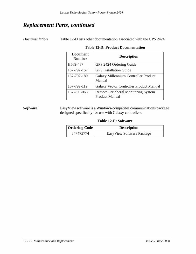
Documentation Table 12-D lists other documentation associated with the GPS 242
Software EasyView software is a Windows-compatible communications packagdesigned specifically for use with Galaxy controllers.
Table 12-D: Product Documentation
Document Number
Description
H569-437 GPS 2424 Ordering Guide
167-792-157 GPS Installation Guide
167-792-180 Galaxy Millennium Controller Product Manual
167-792-112 Galaxy Vector Controller Product Manual
167-790-063 Remote Peripheral Monitoring System Product Manual
Table 12-E: Software
Ordering Code Description
847473774 EasyView Software Package
12 - 12 Maintenance and Replacement Issue 5 June 2000

Lucent Technologies Galaxy Power System 2424
and
tors
13 Troubleshooting Preparations
Preliminary
Introduction This section provides information needed in preparation for locating interpreting visual indicators to help identify problems.
When replacing a part does not correct the problem or visual indicado not identify a defective part, notify the local Regional Technical Assistance Center (RTAC) at 1-800-CAL-RTAC (1-800-225-7822).
Safety Review all safety instructions and warnings in Section 11 before troubleshooting the GPS 2424.
Tools The following tools are necessary in order to troubleshoot the GPS2424:
• 3/16-inch (5 mm) Allen-head wrench
• Insulated hand tools
• Calibrated digital voltmeter (DVM) (0.05% accuracy on dc scale)
• ESD wrist strap
Warnings
• Hazardous ac and dc voltages and/or energy are present. Caution should be exercised. Tools must be insulated to help prevent accidental contact with live surfaces.
• Coordinate all troubleshooting activities with other personnel that may be working on the system.
Issue 5 June 2000 Troubleshooting Preparations 13 - 1

Lucent Technologies Galaxy Power System 2424
uble to the
e
Troubleshooting Procedure
Purpose The troubleshooting procedure described below is used when a trocondition has been identified and a technician has been dispatched system location as a first and fundamental step in diagnosing and correcting the problem.
For all trouble conditions, proceed as follows:
Cabinet Alarm 1. Locate the system Galaxy controller. The controller is typically located in the cabinet identified as BAY ONE. Because a troublcondition exists, the red alarm on the top of the cabinet will be illuminated. See Figure 13-1.
Figure 13-1: Location of Cabinet Alarm
Cabinet Alarm LightVector Controller orBay Interface Card (BIC)
Millennium Controller
13 - 2 Troubleshooting Preparations Issue 5 June 2000
Lucent Technologies Galaxy Power System 2424
larm r
ed,
n. R
Troubleshooting Procedure, continued
System Status 2. Determine the system status. For most problems, one or more aand status LEDs will be illuminated. Depending on the controlletype, the following will be displayed:
– system voltage (all)– system current (Millennium)– system mode (Millennium)– system number of alarm/warnings (Millennium)
If the screen is blank, but alarm and status LEDs are illuminatcall your RTAC representative.
If the entire panel is blank, check the controller fuse (F3 basicpower for the Millennium; F1 on the BLJ board for the Vector).See Figures 13-3 and 13-5. Verify that the controller is getting power. If not, replace fuse. If the display is still blank, call yourRTAC representative.
Alarms Menu 3. To view the Alarms Menu:
• Millennium controller:
If the default screen appears normal, press the MENU buttoThe main menu appears with “Alarms” blinking. Press ENTEto obtain the Alarms menu. Additional data appears that willhelp to identify the problem.
• Vector controller:
Press the View Active Alarms button and use the displayed message code to help identify the problem.
Issue 5 June 2000 Troubleshooting Preparations 13 - 3

Lucent Technologies Galaxy Power System 2424
the
d the the
Troubleshooting Procedure, continued
Troubleshooting Tables
4. Based on the information presented by the alarm LEDs, select appropriate table from the lists below:
Identifying Problems
5. Once the appropriate table is identified, use the status LEDs analarm menu data to identify the specific problem that is causingalarm.
Section 14, Troubleshooting Millennium SystemsAlarm LED Table
AC 14-A, AC AlarmsBATT 14-B, Battery AlarmsBD 14-F, Miscellaneous AlarmsCTRL 14-C, Controller AlarmsDIST 14-D, Distribution AlarmsRECT 14-E, Rectifier and Converter
Related AlarmsRM 14-F, Miscellaneous AlarmsNo LED* 14-F, Miscellaneous Alarms*If an alarm condition exists, but no alarm LED is lit, refer to Table 14-F.
Section 15, Troubleshooting Vector SystemsAlarm LED Table
AC 15-A, AC AlarmsBATT 15-B, Battery AlarmsBD 15-F, Miscellaneous AlarmsCTRL 15-C, Controller AlarmsDIST 15-D, Distribution AlarmsRECT 15-E, Rectifier and Converter
Related AlarmsNo LED* 15-F, Miscellaneous Alarms*If an alarm condition exists, but no alarm LED is lit, refer to Table 15-F.
13 - 4 Troubleshooting Preparations Issue 5 June 2000

Lucent Technologies Galaxy Power System 2424
e
Reference Figures
Figure Numbers and Titles
The following figures are provided for reference while performing thtroubleshooting procedure:
Troubleshooting Reference Figures
Figure No. Title13-1 Location of Cabinet Alarm13-2 Millennium Controller Display
13-3Location of Millennium Controller Fuses and Boards
13-4 Vector Controller Display13-5 Location of Vector Controller Fuses and Boards13-6 Rectifier Display13-7 Converter Status Panels
13-8Low Voltage Battery Disconnect Contactor Control Switches
13-9 Detail of AC Input Panel and Rectifier Shelf13-10 Detail of DC Distribution Panel
13-11Low Voltage Load Disconnect Contactor Control Switches
Issue 5 June 2000 Troubleshooting Preparations 13 - 5

Lucent Technologies Galaxy Power System 2424
, the
nd
n ss w
iled.
Reference Figures, continued
Millennium Controller
Basic Controller
BSH (microprocessor board): After power up, or after a reset, the green and yellow LEDs will both be lit while self diagnostics are in progress (which will take about 10 seconds). If all diagnostics passyellow LED will extinguish and the green LED will remain lit. If a failure is detected during diagnostics, the green LED will extinguish athe yellow LED will remain lit.
If a failure occurs during normal operation, the green LED will extinguish and the yellow LED will light.
Intelligent Controller
BSJ (microprocessor board): After power up, or after a reset, the greeand yellow LEDs will both be lit while self diagnostics are in progre(which will take about 30 seconds). If all diagnostics pass, the yelloLED will extinguish and the green LED will remain lit. If a failure is detected during diagnostics, the green LED will extinguish and the yellow LED will remain lit. If a terminal is attached to the local port during diagnostics, the diagnostic messages will show which test fa
If a failure occurs during normal operation, the green LED will extinguish and the yellow LED will light.
13 - 6 Troubleshooting Preparations Issue 5 June 2000

Lucent Technologies Galaxy Power System 2424
Reference Figures, continued
Millennium Controller, continued
Figure 13-2: Millennium Controller Display
Figure 13-3: Location of Millennium ControllerFuses and Boards
GALAXY MILLENNIUM CONTROLLERMenu Enter Adjust
BD
CRIT
BATT
MAJ
DIST
MIN
RECT
NORM
AC RM
COM
CTRL
LampTest
PlantVoltage
VHelp Escape
Menu Enter AdjustBD
CRIT
BATT
MAJ
DIST
MIN
RECT
NORM
AC RM
COM
CTRL
LampTest
PlantVoltage
VHelp Escape
Alarms
Status
Alarms
Status
BSM Modem BoardBSH Basic Controller Board
BSJ Intelligent Controller Board
BSL Alarm Termination Board
BSW Data Switch Board(mounting location)
Controller FusesF1 - Peripheral Monitor PowerF2 - Intelligent PowerF3 - Basic PowerF4 - Voltage SenseF5 - Alarm Battery Supply
F1 F2 F3 F4 F5
Issue 5 June 2000 Troubleshooting Preparations 13 - 7

Lucent Technologies Galaxy Power System 2424
n
ller ct
Reference Figures, continued
Vector Controller The Control Board is mounted on top of the BLJ terminal connectioboard. The controller issues alarms off the BLJ board. There is a mnemonic abbreviation for each alarm, which is shown on the controdisplay, along with associated alarm LEDs. These mnemonics andrelated alarms are described in the Galaxy Vector Controller produmanual.
Figure 13-4: Vector Controller Display
Figure 13-5: Location of Vector ControllerFuses and Boards
PLANTVOLTAGE
BATTERYTEST
THERMALCOMPENSATION
FLOAT
BOOSTVOLTS
AMPS
ESCAPE
ENTERCONFIGURE
DEFAULT
BD
MAJ
BATT
MIN
DIST
NORM
RECT
ALARMS
STATUS
CTRL
VIEW ACTIVEALARMS
AC
ACO
LAMPTEST
+ –
GALAXY VECTOR CONTROLLER
BLJ Terminal Board
Alarm Battery Supply (ABS)BIC PowerSpare F1Spare F2
BICVector Control Board
F1 -F2 -F3 -F4 -
13 - 8 Troubleshooting Preparations Issue 5 June 2000

Lucent Technologies Galaxy Power System 2424
Reference Figures, continued
Rectifiers During normal operation, the rectifier’s green ON LED will be lit andthe display will show the rectifier’s output current.
Figure 13-6: Rectifier Display
ID
ALM
ON
STBY LIM FANALM
BST
Issue 5 June 2000 Troubleshooting Preparations 13 - 9
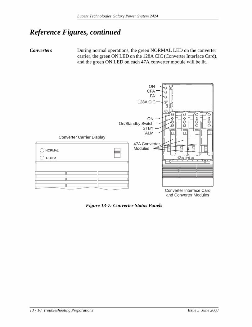
Lucent Technologies Galaxy Power System 2424
er rd),
Reference Figures, continued
Converters During normal operations, the green NORMAL LED on the convertcarrier, the green ON LED on the 128A CIC (Converter Interface Caand the green ON LED on each 47A converter module will be lit.
Figure 13-7: Converter Status Panels
NORMAL
ALARM
ONOn/Standby Switch
STBYALM
ONCFA
FA
Converter Interface Cardand Converter Modules
Converter Carrier Display
47A ConverterModules
128A CIC
13 - 10 Troubleshooting Preparations Issue 5 June 2000
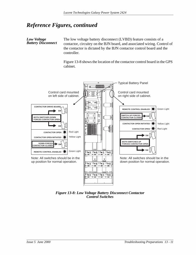
Lucent Technologies Galaxy Power System 2424
l of e
PS
Reference Figures, continued
Low Voltage Battery Disconnect
The low voltage battery disconnect (LVBD) feature consists of a contactor, circuitry on the BJN board, and associated wiring. Controthe contactor is dictated by the BJN contactor control board and thcontroller.
Figure 13-8 shows the location of the contactor control board in the Gcabinet.
Figure 13-8: Low Voltage Battery Disconnect ContactorControl Switches
Red Light
Yellow Light
Green Light
CONTACTOR DRIVE BOARD
SW
SW
SW
BOTH SWITCHES DOWNFORCES CONTACTOR OPEN
CONTACTOR OPEN
CONTACTOR OPEN INITIATED
DOWN FORCESCONTACTOR CLOSED
REMOTE CONTROL ENABLED
Red Light
Yellow Light
Green Light
SW
SW
SW
BOTH SWITCHES UPFORCES CONTACTOR OPEN
CONTACTOR OPEN
CONTACTOR OPEN INITIATED
SWITCH UP FORCESCONTACTOR CLOSED
REMOTE CONTROL ENABLED
Note: All switches should be in thedown position for normal operation.
Note: All switches should be in theup position for normal operation.
Control card mountedon right side of cabinet.
Typical Battery Panel
Control card mountedon left side of cabinet.
Issue 5 June 2000 Troubleshooting Preparations 13 - 11

Lucent Technologies Galaxy Power System 2424
Reference Figures, continued
AC Input
Figure 13-9: Detail of AC Input Panel and Rectifier Shelf
4
8
12
1
5
9
2
6
10
3
7
11
1 12AC Circuit Breakers forRectifiers through
1 2 3 4 5 6 7 8 9 10 11 12
AC Input
Rectifier
596
AC Input Voltage Range176Vac - 264Vac
DC Output
Serial Bus Connectionto Controller
Rectifier Positions
Rectifier or Converter Position
Rectifier Shelf
13 - 12 Troubleshooting Preparations Issue 5 June 2000

Lucent Technologies Galaxy Power System 2424
Reference Figures, continued
DC Distribution
Figure 13-10: Detail of DC Distribution Panel
Alarm Card
Alarm LED
Issue 5 June 2000 Troubleshooting Preparations 13 - 13

Lucent Technologies Galaxy Power System 2424
rd 11.
sed
Reference Figures, continued
Low Voltage Load Disconnect
The EBV low voltage load disconnect (LVLD) contactor control boais mounted on the right side of the cabinet, as shown in Figure 13-
The manual contactor control switch (SW300) is not meant to be uto permanently override the LVLD function. It is only to be used temporarily while servicing or testing the equipment.
Figure 13-11: Low Voltage Load Disconnect ContactorControl Switches
Note: Switch should be in thedown position for normal operation.
Red Light
Yellow Light
Green Light
UP POSITION FORCESCONTACTOR CLOSED
REMOTE CONTROLENABLED
CONTROLLER SIGNALERROR DETECTED
CONTROLLER SIGNALOPENED CONTACTOR
GREEN LIGHT
YELLOW LIGHT ONLY
RED AND YELLOW LIGHT
LOAD DISCONNECT FEATURE IS NOT
FOR USE IN BATTERYLESS SYSTEMS
REMOTECONTROLOVERRIDESWITCH
Control switch mountedon right side of cabinet.
13 - 14 Troubleshooting Preparations Issue 5 June 2000

Lucent Technologies Galaxy Power System 2424
l d
al
14 Troubleshooting Millennium Systems
Introduction
In This Section This section provides information for locating and interpreting visuaindicators to help identify problems in Galaxy Power Systems equippewith the Millennium controller.
Preparation Read Section 13, Troubleshooting Preparations, thoroughly before proceeding.
Technical Assistance
When visual indicators do not identify a defective part, notify the locRegional Technical Assistance Center (RTAC) at 1-800-CAL-RTAC(1-800-225-7822).
Issue 5 June 2000 Troubleshooting Millennium Systems 14 - 1

Lucent Technologies Galaxy Power System 2424
g
Troubleshooting Tables
Organization The tables in this section are organized alphabetically by Alarm LED, then grouped according to the status of the alarm: Critical (CRIT), Major (MAJ), or Minor (MIN).
Table Reference Use the reference below to locate the Alarm LED and correspondintable.
Millennium Display Reference
The Millennium display is illustrated below for quick reference whileusing the troubleshooting tables.
Alarm LED TableAC 14-A, AC AlarmsBATT 14-B, Battery AlarmsBD 14-F, Miscellaneous AlarmsCTRL 14-C, Controller AlarmsDIST 14-D, Distribution AlarmsRECT 14-E, Rectifier and Converter
Related AlarmsRM 14-F, Miscellaneous AlarmsNo LED* 14-F, Miscellaneous Alarms*If an alarm condition exists, but no alarm LED is lit, refer to Table 14-F.
GALAXY MILLENNIUM CONTROLLERMenu Enter Adjust
BD
CRIT
BATT
MAJ
DIST
MIN
RECT
NORM
AC RM
COM
CTRL
LampTest
PlantVoltage
VHelp Escape
Alarms
Status
14 - 2 Troubleshooting Millennium Systems Issue 5 June 2000
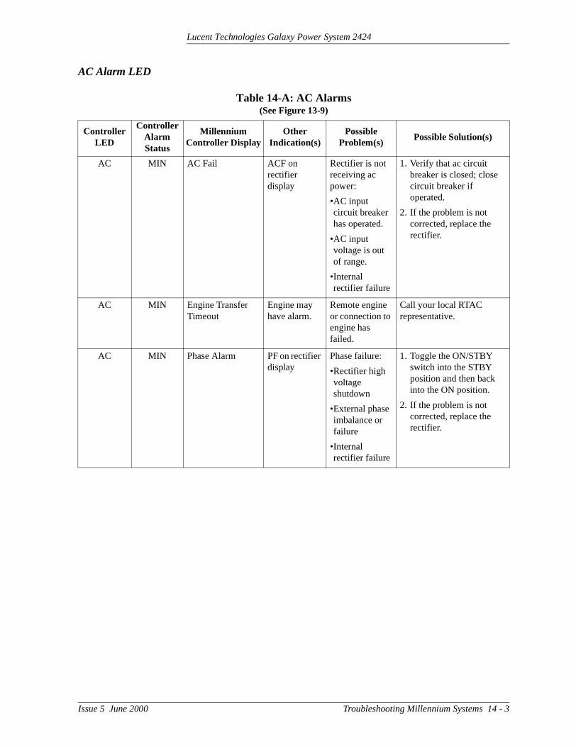
Lucent Technologies Galaxy Power System 2424
AC Alarm LED
Table 14-A: AC Alarms(See Figure 13-9)
Controller LED
Controller Alarm Status
Millennium Controller Display
Other Indication(s)
Possible Problem(s)
Possible Solution(s)
AC MIN AC Fail ACF on rectifier display
Rectifier is not receiving ac power:
•AC input circuit breaker has operated.
•AC input voltage is out of range.
•Internal rectifier failure
1. Verify that ac circuit breaker is closed; close circuit breaker if operated.
2. If the problem is not corrected, replace the rectifier.
AC MIN Engine Transfer Timeout
Engine may have alarm.
Remote engine or connection to engine has failed.
Call your local RTAC representative.
AC MIN Phase Alarm PF on rectifier display
Phase failure:
•Rectifier high voltage shutdown
•External phase imbalance or failure
•Internal rectifier failure
1. Toggle the ON/STBY switch into the STBY position and then back into the ON position.
2. If the problem is not corrected, replace the rectifier.
Issue 5 June 2000 Troubleshooting Millennium Systems 14 - 3

Lucent Technologies Galaxy Power System 2424
BATT Alarm LED
Table 14-B: Battery Alarms(See Figure 13-8)
Controller LED
Controller Alarm Status
Millennium Controller Display
Other Indication(s)
Possible Problem(s)
Possible Solution(s)
BATT CRIT Very Low Voltage -- Occurs in an operating system following an extended commercial ac power outage, during which the batteries are providing power for the system and the system voltage is approaching the user-defined low limit.
1. If commercial ac power is present but the system voltage remains low, call your local RTAC representative.
2. Investigate other alarms that may be present (rectifier-related alarms and the AC Fail alarm may also occur during the fault condition).
BATT*
*Alarm must be configuredto turn on the BATT LED; not a factory default.
MAJ Contactor 1 Open Red LED on contactor drive board is lit.
Contactor is open:
•Open has been initiated by controller.
•Open has been initiated manually.
1. Follow instructions on the label adjacent to the contactor drive board (see Figure 13-8).
2. If the problem is not corrected, call your local RTAC representative.
BATT*
*Alarm must be configuredto turn on the BATT LED; not a factory default.
MAJ Contactor 1 Fail -- Contactor or drive board has failed.
Call your local RTAC representative.
BATT MIN Open String Alarm LED on battery fuse panel is lit.
Battery fuse has operated or battery string switch has opened.
Replace the operated fuse.
14 - 4 Troubleshooting Millennium Systems Issue 5 June 2000

Lucent Technologies Galaxy Power System 2424
BATT MIN Low Reserve Time -- Controller has calculated that battery reserve time is below the alarm threshold level.
Call your local RTAC representative.
BATT MIN Battery Thermal Alarm
Alarm on 210E unit, if equipped
Batteries have exceeded temp threshold
•Check room ambient temperature against battery temperature threshold
•Call your local RTAC representative
Table 14-B: Battery Alarms(See Figure 13-8)
Controller LED
Controller Alarm Status
Millennium Controller Display
Other Indication(s)
Possible Problem(s)
Possible Solution(s)
Issue 5 June 2000 Troubleshooting Millennium Systems 14 - 5

Lucent Technologies Galaxy Power System 2424
CTRL Alarm LED
Table 14-C: Controller Alarms(See Figures 13-2 and 13-3)
Controller LED
Controller Alarm Status
Millennium Controller Display
Other Indication(s)
Possible Problem(s)
Possible Solution(s)
CTRL MAJ Controller Fail -- •BSH failure →•BSJ failure
•Option board failure
•Display failure
•BIC failure
Check the BSH board to seeif the green LED is extinguished and the yellow LED is lit. If so, perform the following steps:
1. Press the SW200 reset switch on the top of the BSH board. If all diagnostics pass, it is possible that some type of “one time” abnormality occurred to cause the failure.
2. If the diagnostics did not pass, or if the problem recurs, unplug all the optional circuit board cables, then press the reset switch on the top of the BSH board again. If all the diagnostics pass, install optional circuit board cables one at a time, verifying operation after each.
3. If the diagnostics did not pass, Replace the BSH board and verify the failure is resolved. If so, reinstall the optional circuit boards and cables one at a time.
4. If the problem is not corrected, call your local RTAC representative.
14 - 6 Troubleshooting Millennium Systems Issue 5 June 2000

Lucent Technologies Galaxy Power System 2424
CTRL MAJ Controller Fail -- •BSH failure•BSJ failure→•Option board failure
•Display failure
•BIC failure
Check the BSJ board to seeif the green LED is extinguished and the yellow LED is lit. If so, perform the following steps:
1. Press the SW201 reset switch on the top of the BSJ board. (This circuit has an automatic restart, which will try three times to restart the microprocessor.)
2. If the diagnostics did not pass, or if the problem recurs, remove all the optional circuit board cables, then press the reset switch on the top of the BSJ board again. If all the diagnostics pass, install optional circuit board cables one at a time, verifying operation after each.
3. If the diagnostics did not pass, replace the BSJ board and verify the failure is resolved. If so, reinstall the optional circuit boards and cables one at a time.
4. If the problem is not corrected, call your local RTAC representative.
Table 14-C: Controller Alarms(See Figures 13-2 and 13-3)
Controller LED
Controller Alarm Status
Millennium Controller Display
Other Indication(s)
Possible Problem(s)
Possible Solution(s)
Issue 5 June 2000 Troubleshooting Millennium Systems 14 - 7

Lucent Technologies Galaxy Power System 2424
CTRL MAJ Controller Fail -- •BSH failure
•BSJ failure
•Option board failure→
•Display failure
•BIC failure
Check the option boards (modem and data switch) to see if the green LED is extinguished and the yellow LED is lit. If so, perform the following steps:
1. Press the SW201 reset switch on the top of the BSJ board. (This circuit has an automatic restart which will try three times to restart the microprocessor.) If the BSJ is not present, press the reset switch on the top of the BSH board.
2. If the diagnostics did not pass, or if the problem recurs, replace the failed option board.
CTRL MAJ Controller Fail -- •BSH failure
•BSJ failure
•Option board failure
•Display failure→
•BIC failure
If the front panel LCD module, LEDs, or switches fail, perform the following steps:
1. Verify that the ribbon cable from the BSH board to the display is not cut, abraded, or otherwise mangled. Replace the cable if damaged.
2. Press SW200 to reset theBSH board.
3. If the LCD module is still not operating, replace the LCD module; if the switches and LEDs are still not operating, replace the BSH board.
Table 14-C: Controller Alarms(See Figures 13-2 and 13-3)
Controller LED
Controller Alarm Status
Millennium Controller Display
Other Indication(s)
Possible Problem(s)
Possible Solution(s)
14 - 8 Troubleshooting Millennium Systems Issue 5 June 2000

Lucent Technologies Galaxy Power System 2424
CTRL MAJ Controller Fail -- •BSH failure
•BSJ failure
•Option board failure
•Display failure
•BIC failure →
1. Strap K1, K2, K3 on BLJ3 from “C” to “R” prior to replacing BIC. See Figure 9-2.
2. Replace BIC.
CTRL MAJ Circuit Pack Fail -- See “Controller Fail”.
See “Controller Fail”.
CTRL MAJ Controller Fuse -- Fuse has operated.
Replace the controller fuse labeled F2 (intelligent power).
CTRL MAJ Alarm Battery Supply Fuse
-- Fuse has operated.
Replace the controller fuse labeled F5 (alarm battery supply).
CTRL MAJ Remote Peripheral Fuse
-- Fuse has operated.
Replace the controller fuse labeled F1 (option power).
CTRL MAJ Sense/Control Fuse
-- Fuse has operated.
Replace the controller fuse labeled F4 (voltage sense).
CTRL MAJ Bay Interface ID Conflict
-- Two or more bay interface cards (BICs) have the same ID number.
Following instructions printed on the label over the BIC, adjust the DIP switches to change the ID number.
CTRL MAJ Major Communication Fail Alarm
Blinking ALM LED on rectifiers or
blinking CFA LED on converter interface cards
or
red LED on BIC
Loss of communication with controller:
•Defective interface from BIC, multiple rectifiers, or multiple converters to controller
•Internal failure of controller, BIC, multiple rectifiers, or multiple converters
1. Verify that the controller is powered and operating correctly.
2. If there are no controller alarms, replace the equipment that has lost communication.
3. If the problem is not corrected, call your local RTAC representative.
Table 14-C: Controller Alarms(See Figures 13-2 and 13-3)
Controller LED
Controller Alarm Status
Millennium Controller Display
Other Indication(s)
Possible Problem(s)
Possible Solution(s)
Issue 5 June 2000 Troubleshooting Millennium Systems 14 - 9

Lucent Technologies Galaxy Power System 2424
CTRL MIN Minor Communication Fail Alarm
Blinking ALM LED on rectifier or
blinking CFA LED on converter interface card
Loss of communication with controller:
•Defective interface from rectifier or converter to controller
•Internal failure of controller, rectifier, or converter
1. Verify that the controller is powered and operating correctly.
2. If there are no controller alarms, replace the equipment that has lost communication.
3. If the problem is not corrected, call your local RTAC representative.
CTRL MIN Self Fail Test -- See “Controller Fail”.
See “Controller Fail”.
CTRL MIN Thermal Probe Failure
-- Battery thermal probe has failed.
Call your local RTAC representative.
Table 14-C: Controller Alarms(See Figures 13-2 and 13-3)
Controller LED
Controller Alarm Status
Millennium Controller Display
Other Indication(s)
Possible Problem(s)
Possible Solution(s)
14 - 10 Troubleshooting Millennium Systems Issue 5 June 2000

Lucent Technologies Galaxy Power System 2424
DIST Alarm LED
Table 14-D: Distribution Alarms(See Figures 13-10 and 13-11)
Controller LED
Controller Alarm Status
Millennium Controller Display
Other Indication(s)
Possible Problem(s)
Possible Solution(s)
DIST MAJ External Fuse Major
Alarm LED on dc distribution panel is lit.
DC load fuse or circuit breaker has operated.
Replace fuse or reset circuit breaker.
DIST MAJ Converter Distribution Fuse
FA LED on converter carrier
A fuse or circuit breaker in the converter distribution has operated.
Replace fuse or reset circuit breaker.
DIST*
*Alarm must be configuredto turn on the DIST LED; not a factory default.
MAJ Contactor 2 (or 3) Open
Red LED on contactor drive board is lit.
Contactor is open:
•Open has been initiated by controller.
•Open has been initiated manually.
1. Follow instructions on the label adjacent to the contactor drive board (see Figure 13-11).
2. If the problem is not corrected, call your local RTAC representative.
DIST*
*Alarm must be configuredto turn on the DIST LED; not a factory default.
MAJ Contactor 2 (or 3) Fail
-- Contactor or drive board has failed.
Call your local RTAC representative.
Issue 5 June 2000 Troubleshooting Millennium Systems 14 - 11

Lucent Technologies Galaxy Power System 2424
RECT Alarm LED
Table 14-E: Rectifier and Converter Related AlarmsRectifier Related Alarms
(See Figures 13-6 and 13-9)
Controller LED
Controller Alarm Status
Millennium Controller Display
Rectifier LED
Rectifier Display
Possible Problem(s)
Possible Solution(s)
RECT MAJ ID Not Configured None None Rectifier ID number has not been set.
1. Press ON/STBY switch up and hold for five seconds until display starts blinking “0”.
2. Release switch; display should continue to blink.
3. Depress switch and release. Display will increment up one number on each release of the switch, but will remain flashing.
4. Once the desired ID number appears, depress and hold the switch for five seconds. The display will cease to blink, and then revert to the rectifier current.
RECT MAJ ID Conflict None None Two or more rectifiers have the same ID number.
See above.
RECT MAJ Multiple Rectifier Fail
ALM None More than one rectifier has an ALM LED lit.
See alarms listed below.
RECT MAJ High Voltage Alarm
ALM HO •Lightning has struck system.
•Internal rectifier failure
1. Toggle the ON/STBY switch into the STBY position and then back into the ON position.
2. If the problem is not corrected, replace the rectifier.
14 - 12 Troubleshooting Millennium Systems Issue 5 June 2000

Lucent Technologies Galaxy Power System 2424
RECT MIN Rectifier Fail ALM HO High output voltage:
•Rectifier high voltage shutdown
•Internal rectifier failure
1. Verify the configurable HV thresholds in the controller.
2. Toggle the ON/STBY switch into the STBY position and then back into the ON position.
3. If the problem is not corrected, replace the rectifier.
RECT MIN Rectifier Fail ALM TA Thermal alarm:
•Excessive ambient temperature
•Internal rectifier failure
1. Verify that there is no obstruction of the fan inlet.
2. Toggle the ON/STBY switch into the STBY position and then back into the ON position.
3. If the problem is not corrected, replace the rectifier.
RECT MIN Rectifier Fail ALM CB Circuit breaker alarm:
•DC output circuit breaker open
•Internal rectifier failure
1. Toggle the ON/STBY switch into the STBY position; toggle the DC output circuit breaker into the OFF position and then into the ON position. Return the ON/STBY switch to the ON position.
2. If the problem is not corrected, replace the rectifier.
Table 14-E: Rectifier and Converter Related AlarmsRectifier Related Alarms
(See Figures 13-6 and 13-9)
Controller LED
Controller Alarm Status
Millennium Controller Display
Rectifier LED
Rectifier Display
Possible Problem(s)
Possible Solution(s)
Issue 5 June 2000 Troubleshooting Millennium Systems 14 - 13

Lucent Technologies Galaxy Power System 2424
RECT MIN Rectifier Fail ALM ICS
IP5
IP6
IP7
Internal rectifier failure
1. Place the ac circuit breaker for the rectifier in the OFF position.
2. Remove the rectifier from the shelf.
3. Wait for 30 seconds or until all front panel display LEDs have extinguished.
4. Replace the rectifier.
5. Return the ac breaker to the ON position.
6. Place the rectifier ON/STBY switch into the ON position.
7. If the problem is not corrected, replace the rectifier.
RECT MIN Rectifier Fail ALM FSE Fuse alarm:
•DC fuse open
•Internal rectifier failure
1. Toggle the ON/STBY switch into the STBY position and then back into the ON position.
2. If the problem is not corrected, replace the rectifier.
RECT MIN Rectifier Fail ALM LO Low output voltage:
•Excessive output current
•Internal rectifier failure
1. Toggle the ON/STBY switch into the STBY position and then back into the ON position.
2. If the problem is not corrected, replace the rectifier.
Table 14-E: Rectifier and Converter Related AlarmsRectifier Related Alarms
(See Figures 13-6 and 13-9)
Controller LED
Controller Alarm Status
Millennium Controller Display
Rectifier LED
Rectifier Display
Possible Problem(s)
Possible Solution(s)
14 - 14 Troubleshooting Millennium Systems Issue 5 June 2000

Lucent Technologies Galaxy Power System 2424
RECT MIN Rectifier Fail ALM SEN Thermal sensor failure:
•Internal rectifier failure
1. Place the ac circuit breaker for the rectifier in the OFF position.
2. Remove the rectifier from the shelf.
3. Wait for 30 seconds or until all front panel display LEDs have extinguished.
4. Replace the rectifier.
5. Return the ac breaker to the ON position.
6. Place the rectifier ON/STBY switch into the ON position.
7. If the problem is not corrected, replace the rectifier with a new one.
RECT MIN Rectifier Fail FAN ALM
None Fan failure Replace the fan in the rectifier.
RECT MIN Manual Off STBY Blank Rectifier has been manually turned off.
Turn rectifier on.
RECT MIN External Transfer Shutdown
STBY TR System is operating on external engine.
No action required.
RECT MIN High Float Voltage None None Configuration problem
Call your local RTAC representative.
RECT MIN Excess Rectifier Drain
None None Internal rectifier fault
Replace rectifier.
RECT MIN Excess System Drain
None None System load exceeds shunt rating.
Call your local RTAC representative.
Table 14-E: Rectifier and Converter Related AlarmsRectifier Related Alarms
(See Figures 13-6 and 13-9)
Controller LED
Controller Alarm Status
Millennium Controller Display
Rectifier LED
Rectifier Display
Possible Problem(s)
Possible Solution(s)
Issue 5 June 2000 Troubleshooting Millennium Systems 14 - 15

Lucent Technologies Galaxy Power System 2424
RECT MIN Limited Recharge None None Rectifier capacity has been exceeded.
Install more rectifiers.
RECT MIN External Transfer Shutdown
STBY TR System is operating on external engine.
No action required.
Converter Related Alarms(See Figure 13-7)
Controller LED
Controller Alarm Status
Millennium Controller Display
Converter LEDPossible
Problem(s)Possible Solution(s)
RECT MAJ Multiple Converter Fail
CFA •More than one converter modules are turned off. (STBY LEDs are lit.)
•More than one converter module has failed.
1. Turn on modules if off.
2. Replace modules.
RECT MAJ Converter Fan Major
CFA Both fans in a converter carrier have failed.
Replace fans.
RECT MAJ Converter ID Conflict
None Two or more converters have the same ID number.
1. Pull CIC card out of carrier.
2. Move plastic tab.
3. Set DIP switches.
4. Call your local RTAC representative for assistance.
Table 14-E: Rectifier and Converter Related AlarmsRectifier Related Alarms
(See Figures 13-6 and 13-9)
Controller LED
Controller Alarm Status
Millennium Controller Display
Rectifier LED
Rectifier Display
Possible Problem(s)
Possible Solution(s)
14 - 16 Troubleshooting Millennium Systems Issue 5 June 2000

Lucent Technologies Galaxy Power System 2424
Converter Related Alarms(See Figure 13-7)
Controller LED
Controller Alarm Status
Millennium Controller Display
Converter LEDPossible
Problem(s)Possible Solution(s)
RECT MIN Converter Fail CFA •Converter module manually turned off (STBY LED is lit.)
•Converter module failure
1. Turn on module if off.
2. Replace module.
RECT MIN Converter Fan Minor
CFA One fan in a converter carrier has failed.
Replace fan.
Issue 5 June 2000 Troubleshooting Millennium Systems 14 - 17

Lucent Technologies Galaxy Power System 2424
BD and RM Alarm LEDs, or No LED
Table 14-F: Miscellaneous Alarms
Controller LED
Controller Alarm Status
Millennium Controller Display
Other Indication(s)
Possible Problem(s)
Possible Solution(s)
BD MAJ Battery on Discharge
Rectifiers may say ACF.
Temporary condition that may be associated with other alarms
Call your local RTAC representative.
RM MIN Module Failure Green LED on RPM will not blink.
Remote Peripheral Module has failed.
Call your local RTAC representative.
RM MIN Measurement Out of Range
-- •Data being sensed exceeds remote peripheral module’s capability.
•Remote peripheral module has failed.
Call your local RTAC representative.
None MAJ Auxiliary Major Auxiliary equipment may have alarm.
Problem with operation of auxiliary equipment
Call your local RTAC representative.
None MIN Auxiliary Minor Auxiliary equipment may have alarm.
Problem with operation of auxiliary equipment
Call your local RTAC representative.
None None None •STBY LED on rectifier is lit.
•TR on rectifier display
Remote transfer:
•Rectifier is in STBY.
Remove the remote standby command issued by the controller.
None None None Red LED is lit on some battery contactor drive boards, while green LED is lit on others.
If a green LED is lit despite a contactor open command issued by the controller, the drive card or the contactor has failed.
Call your local RTAC representative.
14 - 18 Troubleshooting Millennium Systems Issue 5 June 2000

Lucent Technologies Galaxy Power System 2424
l d
al
15 Troubleshooting Vector Systems
Introduction
In This Section This section provides information for locating and interpreting visuaindicators to help identify problems in Galaxy Power Systems equippewith the Vector controller.
Preparation Read Section 13, Troubleshooting Preparations, thoroughly before proceeding.
Technical Assistance
When visual indicators do not identify a defective part, notify the locRegional Technical Assistance Center (RTAC) at 1-800-CAL-RTAC(1-800-225-7822).
Issue 5 June 2000 Troubleshooting Vector Systems 15 - 1

Lucent Technologies Galaxy Power System 2424
nor
g
Troubleshooting Tables
Organization The tables in this section are organized alphabetically by Alarm LED, then grouped according to the status of the alarm, Major (MAJ) or Mi(MIN).
Table Reference Use the reference below to locate the Alarm LED and correspondintable.
Vector Display Reference
The Vector front display is shown below.
Alarm LED TableAC 15-A, AC AlarmsBATT 15-B, Battery AlarmsBD 15-F, Miscellaneous AlarmsCTRL 15-C, Controller AlarmsDIST 15-D, Distribution AlarmsRECT 15-E, Rectifier and Converter
Related AlarmsNo LED* 15-F, Miscellaneous Alarms*If an alarm condition exists, but no alarm LED is lit, refer to Table 15-F.
PLANTVOLTAGE
BATTERYTEST
THERMALCOMPENSATION
FLOAT
BOOSTVOLTS
AMPS
ESCAPE
ENTERCONFIGURE
DEFAULT
BD
MAJ
BATT
MIN
DIST
NORM
RECT
ALARMS
STATUS
CTRL
VIEW ACTIVEALARMS
AC
ACO
LAMPTEST
+ –
GALAXY VECTOR CONTROLLER
15 - 2 Troubleshooting Vector Systems Issue 5 June 2000

Lucent Technologies Galaxy Power System 2424
AC Alarm LED
Table 15-A: AC Alarms(See Figure 13-9)
Controller LED
Controller Alarm Status
Vector Controller Display
Other Indication(s)
Possible Problem(s)
Possible Solution(s)
AC MAJ nACF ACF on rectifier display
Rectifier(s) not receiving ac power:
•AC input circuit breaker has operated.
•AC input voltage is out of range.
•Internal rectifier failure
1. Verify that ac circuit breaker is closed; close circuit breaker if operated.
2. If the problem is not corrected, replace the rectifier(s).
AC MIN ACF ACF on rectifier display
Rectifier not receiving ac power:
•AC input circuit breaker has operated.
•AC input voltage is out of range.
•Internal rectifier failure
1. Verify that ac circuit breaker is closed; close circuit breaker if operated.
2. If the problem is not corrected, replace the rectifier.
AC MIN ACF PF on rectifier display
Phase failure:
•Rectifier high voltage shutdown
•External phase imbalance or failure
•Internal rectifier failure
1. Toggle the ON/STBY switch into the STBY position and then back into the ON position.
2. If the problem is not corrected, replace the rectifier.
Issue 5 June 2000 Troubleshooting Vector Systems 15 - 3

Lucent Technologies Galaxy Power System 2424
BATT Alarm LED
Table 15-B: Battery Alarms(See Figure 13-8)
Controller LED
Controller Alarm Status
Vector Controller Display
Other Indication(s)
Possible Problem(s)
Possible Solution(s)
BATT MAJ LLO -- Occurs in an operating system following an extended commercial ac power outage, during which the batteries are providing power for the system and the system voltage is approaching the user-defined low limit.
1. If commercial ac power is present but the system voltage remains low, call your local RTAC representative.
2. Investigate other alarms that may be present (rectifier-related alarms and the AC Fail alarm may also occur during the fault condition).
BATT MAJ C1O Red LED on contactor drive board is lit.
Contactor is open:
•Open has been initiated by controller.
•Open has been initiated manually.
1. Follow instructions on the label adjacent to the contactor drive board (see Figure 13-8).
2. If the problem is not corrected, call your local RTAC representative.
BATT MAJ C1F -- Contactor or drive board has failed.
Call your local RTAC representative.
BATT MAJ bta Alarm on 210E unit, if equipped
Batteries have exceeded temperature threshold.
Call your local RTAC representative.
15 - 4 Troubleshooting Vector Systems Issue 5 June 2000

Lucent Technologies Galaxy Power System 2424
CTRL Alarm LED
Table 15-C: Controller Alarms(See Figures 13-4 and 13-5)
Controller LED
Controller Alarm Status
Vector Controller Display
Other Indication(s)
Possible Problem(s)
Possible Solution(s)
CTRL MAJ None -- •Controller failure
Check controller to see if the green LED is extinguished and the red LED is lit. If so, perform the following steps:
1. Remove and reset the controller circuit board. If all diagnostics pass, it is possible that some type of “one time” abnormality occurred to cause the failure.
2. If the diagnostics did not pass, replace the controller circuit board and verify the failure is resolved.
3. If the problem is not corrected, call your local RTAC representative.
CTRL MAJ None -- •Controller failure
•Display failure
If the front panel LED module, LEDs, or switches fail, perform the following steps:
1. Verify that the ribbon cable from the controller board to the BMW display is not cut, abraded, or otherwise mangled. Replace the cable if damaged.
2. Reset the controller board.
3. If the display is still not operating, replace the display module.
CTRL MIN tPA -- Battery thermal probe has failed.
Call your local RTAC representative.
Issue 5 June 2000 Troubleshooting Vector Systems 15 - 5

Lucent Technologies Galaxy Power System 2424
DIST Alarm LED
Table 15-D: Distribution Alarms(See Figures 13-10 and 13-11)
Controller LED
Controller Alarm Status
Vector Controller Display
Other Indication(s)
Possible Problem(s)
Possible Solution(s)
DIST MAJ CdSt FA LED on converter is lit.
A fuse or circuit breaker in the converter distribution has operated.
Replace fuse or reset circuit breaker.
DIST MAJ C2O Red LED on contactor drive board is lit.
Contactor is open:
•Open has been initiated by controller.
•Open has been initiated manually.
1. Follow instructions on the label adjacent to the contactor drive board (see Figure 13-11).
2. If the problem is not corrected, call your local RTAC representative.
DIST MAJ C2F -- Contactor or drive board has failed.
Call your local RTAC representative.
DIST MAJ FAJ Alarm LED on dc distribution panel is lit.
DC load fuse or circuit breaker has operated.
Replace fuse or reset circuit breaker.
DIST MAJ FAJ -- Fuse has operated.
Replace the controller fuse labeled F2 (alarm battery supply).
15 - 6 Troubleshooting Vector Systems Issue 5 June 2000

Lucent Technologies Galaxy Power System 2424
RECT Alarm LED
Table 15-E: Rectifier and Converter Related Alarms
Rectifier Related Alarms(See Figures 13-6 and 13-9)
Controller LED
Controller Alarm Status
Vector Controller Display
Rectifier LED
Rectifier Display
Possible Problem(s)
Possible Solution(s)
RECT MAJ rid None None Rectifier ID number has not been set.
1. Press ON/STBY switch up and hold for five seconds until display starts blinking “0”.
2. Release switch; display should continue to blink.
3. Depress switch and release. Display will increment up one number on each release of the switch, but will remain flashing.
4. Once the desired ID number appears, depress and hold the switch for five seconds. The display will cease to blink, and then revert to the rectifier current.
RECT MAJ rid None None Two or more rectifiers have the same ID number.
See above.
RECT MAJ nrFA ALM None More than one rectifier has an ALM LED lit.
See rectifier alarms listed below.
Issue 5 June 2000 Troubleshooting Vector Systems 15 - 7

Lucent Technologies Galaxy Power System 2424
RECT MAJ nrFA -- -- Loss of communication with controller:
•Defective interface from multiple rectifiers to controller
•Internal failure of controller or multiple rectifiers
1. Verify that the controller is powered and operating correctly.
2. If there are no controller alarms, replace rectifiers that have lost communication.
3. If the problem is not solved, call your local RTAC representative.
RECT MAJ HO ALM HO •Lightning has struck system.
•Internal rectifier failure
1. Toggle the ON/STBY switch into the STBY position and then back into the ON position.
2. If the problem is not corrected, replace the rectifier.
RECT MIN rFA BlinkingALM LED on rectifier
-- Loss of communication with controller:
•Defective interface from rectifier to controller
•Internal controller or rectifier failure
1. Verify that the controller is powered and operating correctly.
2. If there are no controller alarms, replace the rectifier.
3. If the problem is not corrected, call your local RTAC representative.
Table 15-E: Rectifier and Converter Related Alarms
Rectifier Related Alarms(See Figures 13-6 and 13-9)
Controller LED
Controller Alarm Status
Vector Controller Display
Rectifier LED
Rectifier Display
Possible Problem(s)
Possible Solution(s)
15 - 8 Troubleshooting Vector Systems Issue 5 June 2000
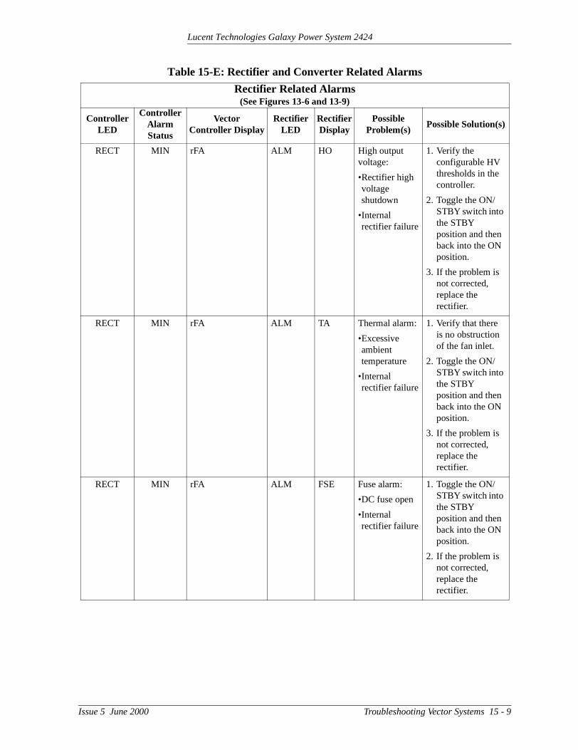
Lucent Technologies Galaxy Power System 2424
RECT MIN rFA ALM HO High output voltage:
•Rectifier high voltage shutdown
•Internal rectifier failure
1. Verify the configurable HV thresholds in the controller.
2. Toggle the ON/STBY switch into the STBY position and then back into the ON position.
3. If the problem is not corrected, replace the rectifier.
RECT MIN rFA ALM TA Thermal alarm:
•Excessive ambient temperature
•Internal rectifier failure
1. Verify that there is no obstruction of the fan inlet.
2. Toggle the ON/STBY switch into the STBY position and then back into the ON position.
3. If the problem is not corrected, replace the rectifier.
RECT MIN rFA ALM FSE Fuse alarm:
•DC fuse open
•Internal rectifier failure
1. Toggle the ON/STBY switch into the STBY position and then back into the ON position.
2. If the problem is not corrected, replace the rectifier.
Table 15-E: Rectifier and Converter Related Alarms
Rectifier Related Alarms(See Figures 13-6 and 13-9)
Controller LED
Controller Alarm Status
Vector Controller Display
Rectifier LED
Rectifier Display
Possible Problem(s)
Possible Solution(s)
Issue 5 June 2000 Troubleshooting Vector Systems 15 - 9

Lucent Technologies Galaxy Power System 2424
RECT MIN rFA ALM LO Low output voltage:
•Excessive output current
•Internal rectifier failure
1. Toggle the ON/STBY switch into the STBY position and then back into the ON position.
2. If the problem is not corrected, replace the rectifier.
RECT MIN rFA ALM ICS
IP5
IP6
IP7
Internal rectifier failure
1. Place the ac circuit breaker for the rectifier in the OFF position.
2. Remove the rectifier from the shelf.
3. Wait for 30 seconds or until all front panel display LEDs have extinguished.
4. Replace the rectifier.
5. Return the ac breaker to the ON position.
6. Place the rectifier ON/STBY switch into the ON position.
7. If the problem is not corrected, replace the rectifier.
Table 15-E: Rectifier and Converter Related Alarms
Rectifier Related Alarms(See Figures 13-6 and 13-9)
Controller LED
Controller Alarm Status
Vector Controller Display
Rectifier LED
Rectifier Display
Possible Problem(s)
Possible Solution(s)
15 - 10 Troubleshooting Vector Systems Issue 5 June 2000

Lucent Technologies Galaxy Power System 2424
RECT MIN rFA ALM SEN Thermal sensor failure:
•Internal rectifier failure
1. Place the ac circuit breaker for the rectifier in the OFF position.
2. Remove the rectifier from the shelf.
3. Wait for 30 seconds or until all front panel display LEDs have extinguished.
4. Replace the rectifier.
5. Return the ac breaker to the ON position.
6. Place the rectifier ON/STBY switch into the ON position.
7. If the problem is not corrected, replace the rectifier with a new one.
RECT MIN rFA FAN ALM
None Fan failure Replace the fan in the rectifier.
RECT MIN rOFF STBY Blank Rectifier has been manually turned off.
Turn rectifier on.
RECT MIN HFO None None Configuration problem
Call your local RTAC representative.
Table 15-E: Rectifier and Converter Related Alarms
Rectifier Related Alarms(See Figures 13-6 and 13-9)
Controller LED
Controller Alarm Status
Vector Controller Display
Rectifier LED
Rectifier Display
Possible Problem(s)
Possible Solution(s)
Issue 5 June 2000 Troubleshooting Vector Systems 15 - 11

Lucent Technologies Galaxy Power System 2424
Table 15-E: Rectifier and Converter Related Alarms
Converter Related Alarms(See Figure 13-7)
Controller LED
Controller Alarm Status
VectorController Display
Converter LED
Possible Problem(s)
Possible Solution(s)
RECT MAJ CFJ CFA Both fans in a converter carrier have failed.
Replace fans.
RECT MAJ Cid None 1. Pull CIC card out of carrier.
2. Move plastic tab.
3. Set DIP switches.
4. Call your local RTAC representative for assistance.
RECT MAJ nCFA CFA •More than one converter modules are turned off. (STBY LEDs are lit.)
•More than one converter module have failed.
1. Turn on modules if off.
2. Replace modules.
RECT MAJ nCFA Blinking CFA LED on converter
•Loss of communication with controller
•Defective interface from converters to controller
•Internal failure of controller or multiple converters
1. Verify that the controller is powered and operating correctly.
2. If there are no controller alarms, replace the converter CIC.
3. If the problem is not corrected, call your local RTAC representative.
15 - 12 Troubleshooting Vector Systems Issue 5 June 2000

Lucent Technologies Galaxy Power System 2424
Converter Related Alarms(See Figure 13-7)
Controller LED
Controller Alarm Status
VectorController Display
Converter LED
Possible Problem(s)
Possible Solution(s)
RECT MIN cFA Blinking CFA LED on converter
•Loss of communication with controller
•Defective interface from converter to controller
•Internal controller or converter failure
1. Verify that the controller is powered and operating correctly.
2. If there are no controller alarms, replace the converter CIC.
3. If the problem is not corrected, call your local RTAC representative.
RECT MIN CFA CFA •Converter module manually turned off (STBY LED is lit.)
•Converter module failure
1. Turn on module if off.
2. Replace module.
RECT MIN CFn CFA One fan in a converter carrier has failed.
Replace fan.
Table 15-E: Rectifier and Converter Related Alarms
Issue 5 June 2000 Troubleshooting Vector Systems 15 - 13

Lucent Technologies Galaxy Power System 2424
BD Alarm LED or No LED
Table 15-F: Miscellaneous Alarms
Controller LED
Controller Alarm Status
Vector Controller Display
Other Indication(s)
Possible Problem(s)
Possible Solution(s)
BD MAJ bod Rectifiers may say ACF.
Temporary condition that may be associated with other alarms
Call your local RTAC representative.
None MAJ AUJ Auxiliary equipment may have alarm.
Problem with operation of auxiliary equipment
Call your local RTAC representative.
None None None Red LED is lit on some battery contactor drive boards, while green LED is lit on others.
If a green LED is lit despite a contactor open command issued by the controller, the drive card or the contactor has failed.
Call your local RTAC representative.
None None None -- Fuse has operated.
Replace the controller fuse labeled F1 (power).
15 - 14 Troubleshooting Vector Systems Issue 5 June 2000

Lucent Technologies Galaxy Power System 2424
ight yed
to n
, ler
.
ys its
t to will
16 Product Warranty
A. Seller warrants to Customer only, that:
1. As of the date title to Products passes, Seller will have the rto sell, transfer, and assign such Products and the title conveby Seller shall be good;
2. Upon shipment, Seller’s Manufactured Products will be freefrom defects in material and workmanship, and will conform Seller’s specifications or any other agreed-upon specificatioreferenced in the order for such Product;
3. With respect to Vendor items, Seller, to the extent permitteddoes hereby assign to Customer the warranties given to Selby its Vendor of such Vendor Items, such assignment to be effective upon Customer’s acceptance of such Vendor ItemsWith respect to Vendor items recommended by Seller in its specifications for which the Vendor's warranty cannot be assigned to Customer, or if assigned, less than Sixty (60) daremain of the Vendor's warranty or warranty period when theVendor's items are shipped to Customer or when Seller submits notice of completion of installation if installed by Seller, Seller warrants that such Vendor's items will be free from defects in material and workmanship on the date of shipmenCustomer. In such an event, the applicable Warranty Period be sixty (60) days.
B. The Warranty Period listed below is applicable to Seller’s Manufactured Products furnished pursuant to this Agreement, unless otherwise stated:
Issue 5 June 2000 Product Warranty 16 - 1

Lucent Technologies Galaxy Power System 2424
ity y, o ot se r n d air,
r for y
ng
the d to
l be
iated r.
s
d,
or he
C. If, under normal and proper use during the applicable Warranty Period, a defect or nonconformity is identified in a Product and Customer notifies Seller in writing of such defect or nonconformpromptly after Customer discovers such defect or nonconformitand follows Seller's instructions regarding return of defective ornonconforming Products, Seller shall, at its option attempt first trepair or replace such Product without charge at its facility or, if nfeasible, provide a refund or credit based on the original purchaprice and installation charges if installed by Seller. Where Sellehas elected to repair a Seller’s Manufactured Product (other thaCable and Wire Products) which has been installed by Seller anSeller ascertains that the Product is not readily returnable for repSeller will repair the Product at Customer’s site.
With respect to Cable and Wire Products manufactured by Sellewhich Seller elects to repair but which are not readily returnablerepair, whether or not installed by Seller, Seller at its option, marepair the cable and Wire Products at Customer’s site.
D. If Seller has elected to repair or replace a defective Product, Customer shall have the option of removing and reinstalling or having Seller remove and reinstall the defective or nonconformiProduct. The cost of the removal and the reinstallation shall be borne by Customer. With respect to Cable and Wire Products, Customer has the further responsibility, at its expense, to makeCable and Wire Products accessible for repair or replacement anrestore the site. Products returned for repair or replacement wilaccepted by Seller only in accordance with its instructions and procedures for such returns. The transportation expense assocwith returning such Product to Seller shall be borne by Custome
Warranty Period
Product Type New ProductRepaired Product
or Part*Central Office
Power Equipment**24 Months 6 Months
*The Warranty Period for a repaired Product or part thereof is alisted or, in the case of Products under Warranty, is the period listed or the unexpired term of the new Product Warranty Periowhichever is longer.
**The Warranty Period for Products ordered for Use in SystemsEquipment Manufactured by and furnished by Seller is that of tinitial Systems or equipment.
16 - 2 Product Warranty Issue 5 June 2000

Lucent Technologies Galaxy Power System 2424
ing
n
r ller
ng, ce;
In ich e ,
.
Seller shall pay the cost of transportation of the repair or replacProduct to the destination designated by Customer within the Territory.
E. The defective or nonconforming Products or parts which are replaced shall become Seller's property.
F. If Seller determines that a Product for which warranty service isclaimed is not defective or nonconforming, Customer shall pay Seller all costs of handling, inspecting, testing, and transportatioand, if applicable, traveling and related expenses.
G. Seller makes no warranty with respect to defective conditions ononconformities resulting from actions of anyone other than Seor its subcontractors, caused by any of the following: modifications, misuse, neglect, accident, or abuse; improper wirirepairing, splicing, alteration, installation, storage, or maintenanuse in a manner not in accordance with Seller’s or Vendor’s specifications or operating instructions, or failure of Customer toapply previously applicable Seller modifications and corrections.addition, Seller makes no warranty with respect to Products whhave had their serial numbers or month and year of manufacturremoved, altered, or with respect to expendable items, includingwithout limitation, fuses, light bulbs, motor brushes, and the like
THE FOREGOING WARRANTIES ARE EXCLUSIVE AND ARE IN LIEU OF ALL OTHER EXPRESS AND IMPLIED WARRANTIES, INCLUDING BUT NOT LIMITED TO WARRANTIES OF MERCHANTABILITY AND FI TNESS FOR A PARTICULAR PURPOSE. CUSTOMER’S SOLE AND EXCLUSIVE REMEDY SHALL BE SELLER’S OBLIGATION TO REPAIR, REPLACE, CREDIT, OR REFUND AS SET FORTH ABOVE IN THIS WARRANTY.
© 2000 Lucent TechnologiesAll Rights ReservedPrinted in U.S.A.
Issue 5 June 2000 Product Warranty 16 - 3