Embed Size (px)
Citation preview

www.thalesgroup.com OPEN
LTE SYSTEM DESIGN FOR URBAN LIGHT RAIL TRANSPORT (LRT)
PISTOIA, NOVEMBER 14, 2017
Gianluca MANDÒ
Technical Directorate,
Thales Italia SpA, Italy
Giovanni GIAMBENE
Dipartimento di Ingegneria dell’Informazione e
Scienze Matematiche, University of Siena, Italy
This document may not be reproduced, modified, adapted, published,
translated, in any way, in whole or in part or disclosed to a third party
without the prior written consent of Thales - © Thales 2014 All rights reserved. 2
OPEN
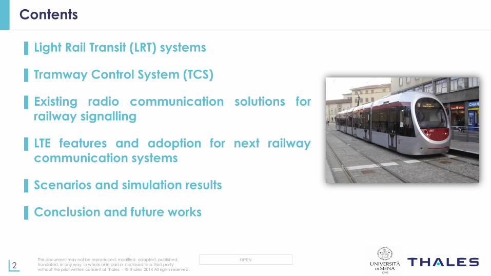
Contents
▌ Light Rail Transit (LRT) systems
▌ Tramway Control System (TCS)
▌Existing radio communication solutions for
railway signalling
▌ LTE features and adoption for next railway
communication systems
▌Scenarios and simulation results
▌Conclusion and future works

This document may not be reproduced, modified, adapted, published,
translated, in any way, in whole or in part or disclosed to a third party
without the prior written consent of Thales - © Thales 2014 All rights reserved. 3
OPEN
Light Rail Transit (LRT) and Tramway Control System (TCS) (1/2)
▌ Tramways:
Are creating environmentally-sustainable cities, enforcing the concept of sustainable mobility within smart
cities
Share their ways with other vehicles (buses, cars, and pedestrians)
Safety in tramways is based on the principle that the train movement is fully controlled by the driver, no level
of automation is allowed
▌ Tramway Control System:
Is the signalling and control system that provides supervision and control over tramway and LRT networks,
including routing and headway management
Is made up of three main building blocks:
- Traffic Manager (TM) at the Operation Control center (OCC) for real-time vehicles localization and
circulation management;
- Interlocking System (IS), which manages LRT signalling alongside and in the depots. It is usually a fault-tolerant system with a high grade of SIL (Safety integrity Level) that controls line switches, track circuits,
axle counters and signals;
- On Board Computer (OBC) to manage on-board signalling, communications and comfort
This document may not be reproduced, modified, adapted, published,
translated, in any way, in whole or in part or disclosed to a third party
without the prior written consent of Thales - © Thales 2014 All rights reserved. 4
OPEN
Light Rail Transit (LRT) and Tramway Control System (TCS) (2/2)
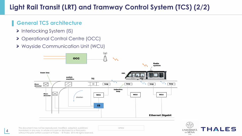
▌ General TCS architecture
Interlocking System (IS)
Operational Control Centre (OCC)
Wayside Communication Unit (WCU)
This document may not be reproduced, modified, adapted, published,
translated, in any way, in whole or in part or disclosed to a third party
without the prior written consent of Thales - © Thales 2014 All rights reserved. 5
OPEN
Radio Communications Services for Urban Transport Systems (1/2)
▌Radio communication services for urban transport systems
Connectivity is one of the key issues for urban guided transport systems
Moving vehicles are connected to ground-based infrastructure by radio
communications that allow a broad range of signalling options than legacy inductive systems
In the past, radio systems have been based on either analogue technology
dedicated to voice or low-bandwidth digital technology
There is the need of adopting new digital mobile technologies with high capacity for urban guided transport systems (train control signalling, passenger security,
and non-critical applications).
This document may not be reproduced, modified, adapted, published,
translated, in any way, in whole or in part or disclosed to a third party
without the prior written consent of Thales - © Thales 2014 All rights reserved. 6
OPEN
Radio Communications Services for Urban Transport Systems (2/2)
▌ These services can be classified into three main categories:
Safety-critical services: signalling traffic
Operational non-safety services: passenger information, CCTV video, IoT
Non-critical applications for infotainment: Internet access for passenger, advertisement, etc.
▌ These services have different Quality of Service (QoS) requirements
Safety-critical services QoS requirements:
- Low throughput (up to 100 kbps)
- Strong requirements in terms of security and reliability
- Availability (at least) 99,99%
- Packet loss rate lower than 10−3
- Delay lower than 200 ms

This document may not be reproduced, modified, adapted, published,
translated, in any way, in whole or in part or disclosed to a third party
without the prior written consent of Thales - © Thales 2014 All rights reserved. 7
OPEN
Existing radio communication solutions for railway and urban guided-transport
▌Radio communication solutions
GSM-R
- Dedicated GSM network for railways
TETRA
- For public safety applications, but low bit-rate
Wi-Fi
- For local wireless networks with limitations in the support of mobility
Necessity of the convergence towards a new broadband railway
communication system that aggregates traffic flows (voice, TCS, CCTV and other services), handling them with proper QoS levels and security policies
LTE is a candidate for railway communications
This document may not be reproduced, modified, adapted, published,
translated, in any way, in whole or in part or disclosed to a third party
without the prior written consent of Thales - © Thales 2014 All rights reserved. 8
OPEN
LTE features overview
▌ LTE Features overview
Peak data rate of 300 Mbps in downlink (DL) and 75 Mbps in uplink (UL)
Fully packet-switched IP-based mobile communication standard
Enhanced support for mobility
Inter-working with previous technologies
Advanced multiple access scheme: OFDMA in DL and SC-FDMA in UL
Adaptive Modulation and Coding (AMC): QPSK, 16-QAM and 64-QAM modulation schemes
Advanced MIMO spatial multiplexing techniques
Enhanced support for end-to-end Quality of Service (QoS)

This document may not be reproduced, modified, adapted, published,
translated, in any way, in whole or in part or disclosed to a third party
without the prior written consent of Thales - © Thales 2014 All rights reserved. 9
OPEN
LTE QoS support
▌ The QoS level in the LTE Evolved Packet System (EPS) is based on the bearer
established between the Packet Data Network Gateway (PDN-GW) and the UE
▌ All the packet flows that are mapped to the same bearer receive a common QoS
treatment (e.g., scheduling policy, queue management policy, shaping policy,
radio link control configuration)
Each bearer is assigned with a QoS Class Identifier (QCI) and an Allocation and Retention
Policy (ARP).
A QCI refers to a set of packet forwarding treatments (e.g., scheduling weights, admission thresholds, queue management thresholds, and link layer protocol configuration) preconfigured by the operator for each network element. There are 9 QCIs levels.
ARP is used in the CAC phase to decide if a bearer establishment/modification request can
be accepted or rejected in case of resource limitation.
This document may not be reproduced, modified, adapted, published,
translated, in any way, in whole or in part or disclosed to a third party
without the prior written consent of Thales - © Thales 2014 All rights reserved. 10
OPEN
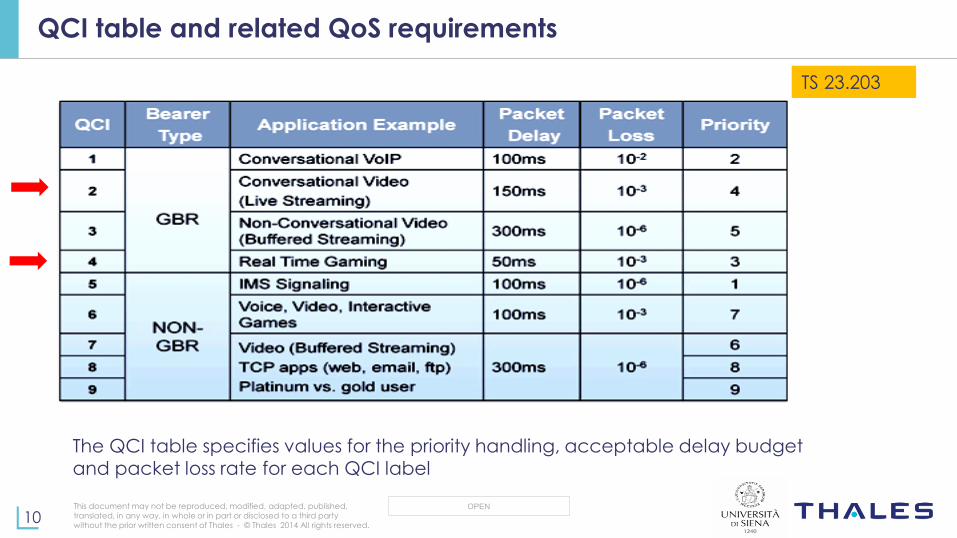
TS 23.203
The QCI table specifies values for the priority handling, acceptable delay budget and packet loss rate for each QCI label
QCI table and related QoS requirements
This document may not be reproduced, modified, adapted, published,
translated, in any way, in whole or in part or disclosed to a third party
without the prior written consent of Thales - © Thales 2014 All rights reserved. 11
OPEN
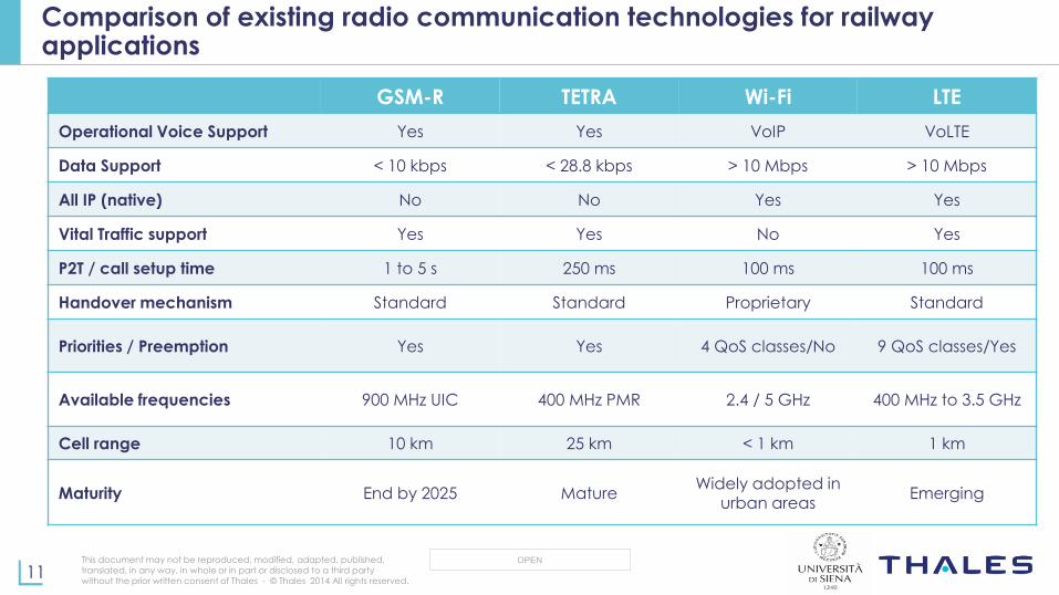
Comparison of existing radio communication technologies for railway applications
GSM-R TETRA Wi-Fi LTE
Operational Voice Support Yes Yes VoIP VoLTE
Data Support < 10 kbps < 28.8 kbps > 10 Mbps > 10 Mbps
All IP (native) No No Yes Yes
Vital Traffic support Yes Yes No Yes
P2T / call setup time 1 to 5 s 250 ms 100 ms 100 ms
Handover mechanism Standard Standard Proprietary Standard
Priorities / Preemption Yes Yes 4 QoS classes/No 9 QoS classes/Yes
Available frequencies 900 MHz UIC 400 MHz PMR 2.4 / 5 GHz 400 MHz to 3.5 GHz
Cell range 10 km 25 km < 1 km 1 km
Maturity End by 2025 Mature Widely adopted in
urban areas Emerging
This document may not be reproduced, modified, adapted, published,
translated, in any way, in whole or in part or disclosed to a third party
without the prior written consent of Thales - © Thales 2014 All rights reserved. 12
OPEN
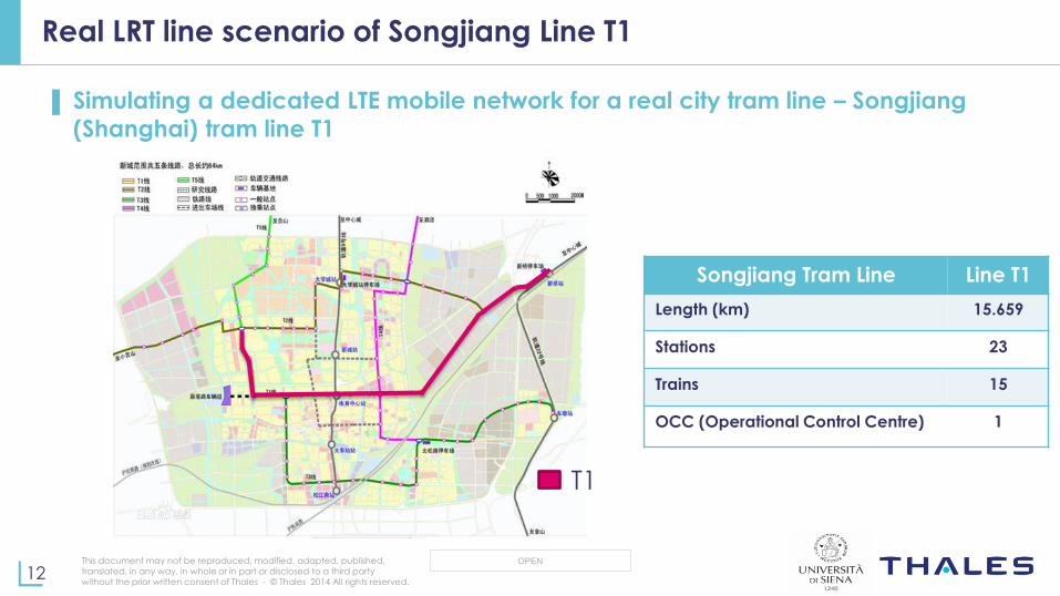
Real LRT line scenario of Songjiang Line T1
▌ Simulating a dedicated LTE mobile network for a real city tram line – Songjiang
(Shanghai) tram line T1
T1
Songjiang Tram Line Line T1
Length (km) 15.659
Stations 23
Trains 15
OCC (Operational Control Centre) 1
This document may not be reproduced, modified, adapted, published,
translated, in any way, in whole or in part or disclosed to a third party
without the prior written consent of Thales - © Thales 2014 All rights reserved. 13
OPEN
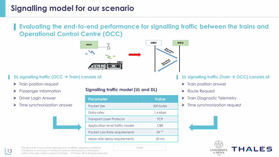
Signalling model for our scenario
▌ Evaluating the end-to-end performance for signalling traffic between the trains and
Operational Control Centre (OCC)
▌ UL signalling traffic (Train OCC) consists of:
Train position answer
Route Request
Train Diagnostic Telemetry
Time synchronization request
▌ DL signalling traffic (OCC Train) consists of:
Train position request
Passenger Information
Driver Login Answer
Time synchronization answer
Parameter Value
Packet size 200 bytes
Data rates 1.6 kbps
Transport Layer Protocol TCP
Application level traffic model CBR
Packet Loss Rate requirements 10−3
Mean e2e delay requirements 50 ms
Signalling traffic model (UL and DL)
This document may not be reproduced, modified, adapted, published,
translated, in any way, in whole or in part or disclosed to a third party
without the prior written consent of Thales - © Thales 2014 All rights reserved. 14
OPEN
NS-3 simulator and LENA module
▌Ns-3 simulator
Is an open-source discrete-event simulator (Linux environment) we have used to
simulate our LRT scenario
ns-3 can model different kinds of communication networks and it offers the
advantage of being modular
- IP level simulator
Being ns-3 and open-source software, we can use existing modules and modify
their code for our purpose
- The work carried out in this paper has been based on the ns-3 LENA (LTE-EPC
Network simulAtor) module that is well-suited to simulate our LRT scenario with an
LTE-based network
- A train is modeled as a User Equipment (UE) with multiple traffic flows (there is no LTE relay onboard).
This document may not be reproduced, modified, adapted, published,
translated, in any way, in whole or in part or disclosed to a third party
without the prior written consent of Thales - © Thales 2014 All rights reserved. 15
OPEN
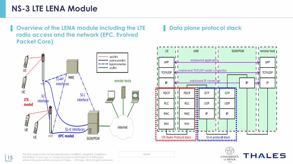
NS-3 LTE LENA Module
▌ Overview of the LENA module including the LTE radio access and the network (EPC, Evolved Packet Core)
▌ Data plane protocol stack

This document may not be reproduced, modified, adapted, published,
translated, in any way, in whole or in part or disclosed to a third party
without the prior written consent of Thales - © Thales 2014 All rights reserved. 16
OPEN
NS-3 LTE LENA Module (cont’d)
▌Possible target applications
Uplink and downlink scheduling
Radio resource management algorithms
Inter cell interference coordination solutions
Mobility management
End-to-End QoS provisioning
▌ Limitations
As for handovers, only intra-frequency X2-handovers are supported
No QoS aware scheduler is implemented for uplink; only Round Robin is available

This document may not be reproduced, modified, adapted, published,
translated, in any way, in whole or in part or disclosed to a third party
without the prior written consent of Thales - © Thales 2014 All rights reserved. 17
OPEN
Simulator implementation
▌ LENA simulation output
Simulation output results can be at different layers: IP, RLC, PDCP, MAC, PHY
▌ Output using FlowMonitor module
The module installs probes in network nodes to track the packet exchanged by the nodes
FlowMonitor captures e2e IP traffic (layer 3)
Packets are classified according to the flow they belong to
Any retransmission caused by layer 4 protocols (e.g., TCP) will be seen by the probes as a new packet
▌ Data collected for each flow from simulations:
Mean packet delay: 𝒅𝒆𝒍𝒂𝒚 =𝒅𝒆𝒍𝒂𝒚𝑺𝒖𝒎
𝒓𝒙𝑷𝒂𝒄𝒌𝒆𝒕𝒔
Packet loss rate: 𝑷𝑳𝑹 =𝒍𝒐𝒔𝒕𝑷𝒂𝒄𝒌𝒆𝒕𝒔
𝒓𝒙𝑷𝒂𝒄𝒌𝒆𝒕𝒔+𝒍𝒐𝒔𝒕𝑷𝒂𝒄𝒌𝒆𝒕𝒔
This document may not be reproduced, modified, adapted, published,
translated, in any way, in whole or in part or disclosed to a third party
without the prior written consent of Thales - © Thales 2014 All rights reserved. 18
OPEN
LTE simulation parameters
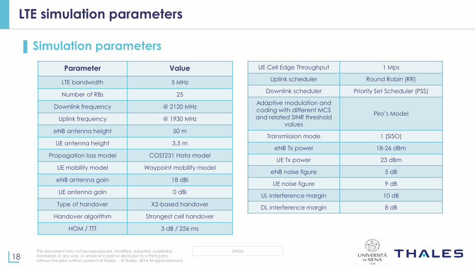
▌Simulation parameters
Parameter Value
LTE bandwidth 5 MHz
Number of RBs 25
Downlink frequency @ 2120 MHz
Uplink frequency @ 1930 MHz
eNB antenna height 50 m
UE antenna height 3.5 m
Propagation loss model COST231 Hata model
UE mobility model Waypoint mobility model
eNB antenna gain 18 dBi
UE antenna gain 0 dBi
Type of handover X2-based handover
Handover algorithm Strongest cell handover
HOM / TTT 3 dB / 256 ms
UE Cell Edge Throughput 1 Mps
Uplink scheduler Round Robin (RR)
Downlink scheduler Priority Set Scheduler (PSS)
Adaptive modulation and
coding with different MCS
and related SINR threshold values
Piro’s Model
Transmission mode 1 (SISO)
eNB Tx power 18-26 dBm
UE Tx power 23 dBm
eNB noise figure 5 dB
UE noise figure 9 dB
UL interference margin 10 dB
DL interference margin 8 dB
This document may not be reproduced, modified, adapted, published,
translated, in any way, in whole or in part or disclosed to a third party
without the prior written consent of Thales - © Thales 2014 All rights reserved. 19
OPEN
Scenario 1: Stationary trains at train depot
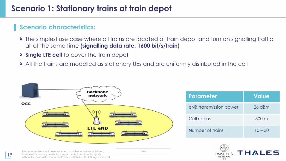
▌ Scenario characteristics:
The simplest use case where all trains are located at train depot and turn on signalling traffic
all at the same time (signalling data rate: 1600 bit/s/train)
Single LTE cell to cover the train depot
All the trains are modelled as stationary UEs and are uniformly distributed in the cell
Parameter Value
eNB transmission power 26 dBm
Cell radius 500 m
Number of trains 15 – 30
This document may not be reproduced, modified, adapted, published,
translated, in any way, in whole or in part or disclosed to a third party
without the prior written consent of Thales - © Thales 2014 All rights reserved. 20
OPEN
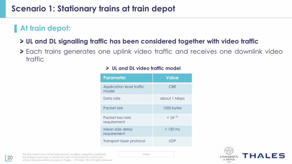
Scenario 1: Stationary trains at train depot
▌At train depot:
UL and DL signalling traffic has been considered together with video traffic
Each trains generates one uplink video traffic and receives one downlink video
traffic
UL and DL video traffic model
Parameter Value
Application level traffic
model
CBR
Data rate about 1 Mbps
Packet size 1000 bytes
Packet loss rate
requirement
< 10−3
Mean e2e delay
requirement
< 150 ms
Transport layer protocol UDP

This document may not be reproduced, modified, adapted, published,
translated, in any way, in whole or in part or disclosed to a third party
without the prior written consent of Thales - © Thales 2014 All rights reserved. 21
OPEN
Scenario 1: Stationary trains at train depot, mean delay and PLR
▌ Mean delay
The mean delay for video is higher than the mean delay for signalling traffic because video traffic entails a higher load
▌ PLR
Is almost zero in the downlink case until 16 trains are considered at the train depot, since the capacity of an LTE cell is sufficient to support all these traffic flows
Video PLR requirements are not fulfilled in uplink, while they are met in downlink when there is
no congestion in the network.
Signalling traffic Video traffic
This document may not be reproduced, modified, adapted, published,
translated, in any way, in whole or in part or disclosed to a third party
without the prior written consent of Thales - © Thales 2014 All rights reserved. 22
OPEN
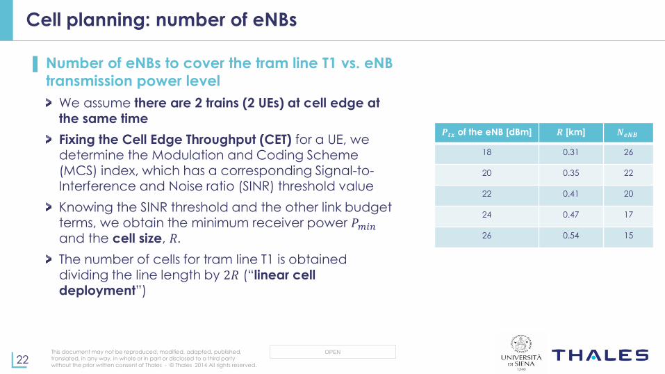
Cell planning: number of eNBs
▌ Number of eNBs to cover the tram line T1 vs. eNB
transmission power level
We assume there are 2 trains (2 UEs) at cell edge at
the same time
Fixing the Cell Edge Throughput (CET) for a UE, we determine the Modulation and Coding Scheme (MCS) index, which has a corresponding Signal-to-
Interference and Noise ratio (SINR) threshold value
Knowing the SINR threshold and the other link budget terms, we obtain the minimum receiver power 𝑃𝑚𝑖𝑛 and the cell size, 𝑅.
The number of cells for tram line T1 is obtained
dividing the line length by 2𝑅 (“linear cell deployment”)
𝑷𝒕𝒙 of the eNB [dBm] 𝑹 [km] 𝑵𝒆𝑵𝑩
18 0.31 26
20 0.35 22
22 0.41 20
24 0.47 17
26 0.54 15
This document may not be reproduced, modified, adapted, published,
translated, in any way, in whole or in part or disclosed to a third party
without the prior written consent of Thales - © Thales 2014 All rights reserved. 23
OPEN
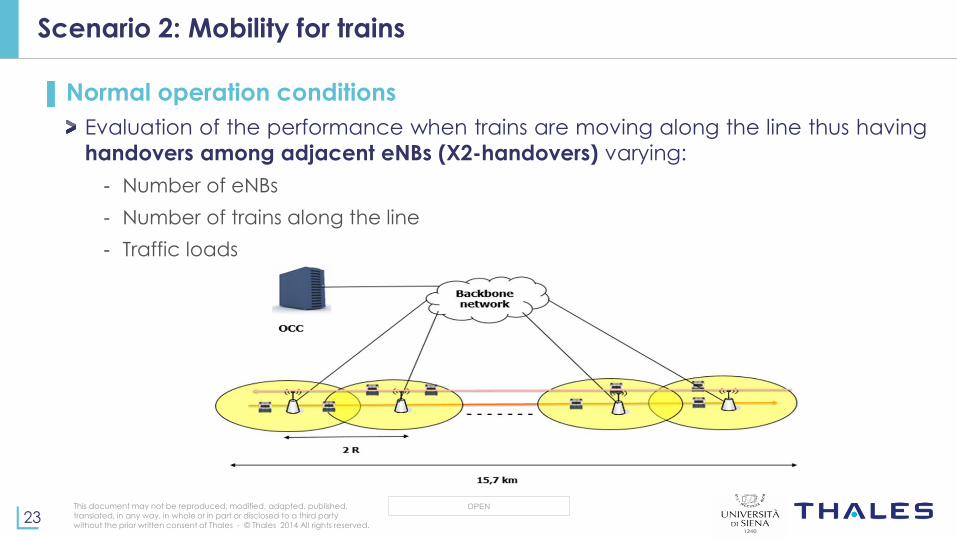
Scenario 2: Mobility for trains
▌Normal operation conditions
Evaluation of the performance when trains are moving along the line thus having
handovers among adjacent eNBs (X2-handovers) varying:
- Number of eNBs
- Number of trains along the line
- Traffic loads
This document may not be reproduced, modified, adapted, published,
translated, in any way, in whole or in part or disclosed to a third party
without the prior written consent of Thales - © Thales 2014 All rights reserved. 24
OPEN
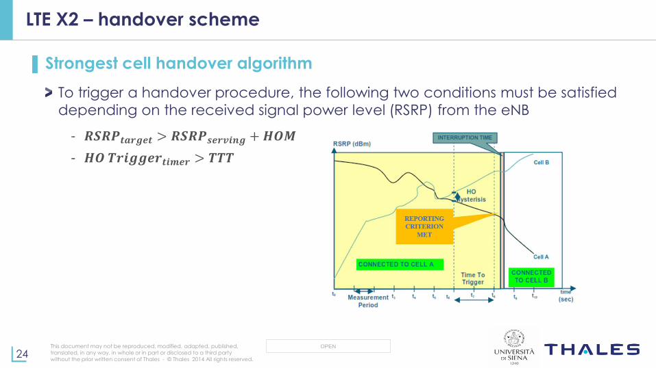
LTE X2 – handover scheme
▌Strongest cell handover algorithm
To trigger a handover procedure, the following two conditions must be satisfied
depending on the received signal power level (RSRP) from the eNB
- 𝑹𝑺𝑹𝑷𝒕𝒂𝒓𝒈𝒆𝒕 > 𝑹𝑺𝑹𝑷𝒔𝒆𝒓𝒗𝒊𝒏𝒈 + 𝑯𝑶𝑴
- 𝑯𝑶 𝑻𝒓𝒊𝒈𝒈𝒆𝒓𝒕𝒊𝒎𝒆𝒓 > 𝑻𝑻𝑻

This document may not be reproduced, modified, adapted, published,
translated, in any way, in whole or in part or disclosed to a third party
without the prior written consent of Thales - © Thales 2014 All rights reserved. 25
OPEN
Scenario 2: Handover performance
▌ Results (only signalling traffic case):
Mean e2e delays are not critical in this simulation scenario
PLR increases when trains have mobility. This increment is mainly due to the failure of handovers that the
trains trigger when moving across different cells
PLR increases with the number of trains, since more trains trigger handovers at the same time and eNBs do
not handle in time the handover procedure
Downlink PLR is higher than uplink one (congestion at the eNB in managing handovers for many UEs)
We can conclude that using higher eNBs transmission powers could improve the PLR performance with
higher transmission costs. However, increasing the eNB transmission power we reduce the number of cells,
thus there could be congestion and performance degradation in terms of delay. A trade-off is needed.
This document may not be reproduced, modified, adapted, published,
translated, in any way, in whole or in part or disclosed to a third party
without the prior written consent of Thales - © Thales 2014 All rights reserved. 26
OPEN
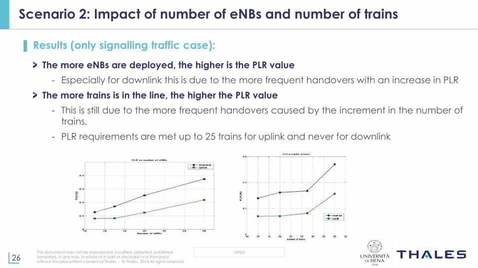
Scenario 2: Impact of number of eNBs and number of trains
▌ Results (only signalling traffic case):
The more eNBs are deployed, the higher is the PLR value
- Especially for downlink this is due to the more frequent handovers with an increase in PLR
The more trains is in the line, the higher the PLR value
- This is still due to the more frequent handovers caused by the increment in the number of trains.
- PLR requirements are met up to 25 trains for uplink and never for downlink
This document may not be reproduced, modified, adapted, published,
translated, in any way, in whole or in part or disclosed to a third party
without the prior written consent of Thales - © Thales 2014 All rights reserved. 27
OPEN
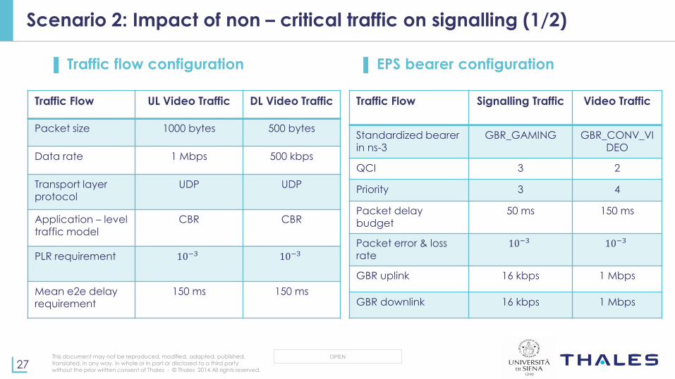
Scenario 2: Impact of non – critical traffic on signalling (1/2)
▌ Traffic flow configuration ▌ EPS bearer configuration
Traffic Flow UL Video Traffic DL Video Traffic
Packet size 1000 bytes 500 bytes
Data rate 1 Mbps 500 kbps
Transport layer protocol
UDP UDP
Application – level
traffic model CBR CBR
PLR requirement 10−3 10−3
Mean e2e delay requirement
150 ms 150 ms
Traffic Flow Signalling Traffic Video Traffic
Standardized bearer in ns-3
GBR_GAMING GBR_CONV_VIDEO
QCI 3 2
Priority 3 4
Packet delay budget
50 ms 150 ms
Packet error & loss
rate
10−3 10−3
GBR uplink 16 kbps 1 Mbps
GBR downlink 16 kbps 1 Mbps
This document may not be reproduced, modified, adapted, published,
translated, in any way, in whole or in part or disclosed to a third party
without the prior written consent of Thales - © Thales 2014 All rights reserved. 28
OPEN
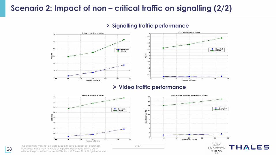
Scenario 2: Impact of non – critical traffic on signalling (2/2)
Signalling traffic performance
Video traffic performance

This document may not be reproduced, modified, adapted, published,
translated, in any way, in whole or in part or disclosed to a third party
without the prior written consent of Thales - © Thales 2014 All rights reserved. 29
OPEN
Conclusions
▌ Results show that:
Major challenges have been investigated when using an LTE-A network for signalling and other services in urban guided transportation systems
An ns-3 simulator based on LTE MODULE has been built implementing the communications for the railway scenario based on Songjiang T2 LRT line
We have demonstrated that PLR requirements in stationary conditions are fulfilled independently of the number of trains in the depot, while PLR performance degrades when
mobility is introduced
We have evaluated the impact of non-critical IT traffic (UDP – based video) on TCP – based signalling
Safety-critical signalling throughput is not affected by video in stationary scenarios, whereas, in the presence of mobility, handovers degrade the signalling performance that can be
guaranteed only if a QoS-aware scheduler is adopted
LTE (in the future LTE-R) technology is a valid candidate for next-generation
railway communications

This document may not be reproduced, modified, adapted, published,
translated, in any way, in whole or in part or disclosed to a third party
without the prior written consent of Thales - © Thales 2014 All rights reserved. 30
OPEN
Next steps
▌ It would be interesting to
Implement inter-frequency handover in ns-3 so that a suitable frequency re-use scheme can be adopted in LTE
Implement suitable QoS-aware schedulers for the uplink traffic as those used for downlink traffic in the LTE module
Evaluate the performance when train operators do not have a dedicated LTE network so that LTE resources are shared with commercial LTE traffic.

This document may not be reproduced, modified, adapted, published,
translated, in any way, in whole or in part or disclosed to a third party
without the prior written consent of Thales - © Thales 2014 All rights reserved. 31
OPEN
Thank you
Thank you!
Email: [email protected]
Email: [email protected]

This document may not be reproduced, modified, adapted, published,
translated, in any way, in whole or in part or disclosed to a third party
without the prior written consent of Thales - © Thales 2014 All rights reserved. 32
OPEN
Spare slides
Pistoia, 14/11/2017
This document may not be reproduced, modified, adapted, published,
translated, in any way, in whole or in part or disclosed to a third party
without the prior written consent of Thales - © Thales 2014 All rights reserved. 33
OPEN
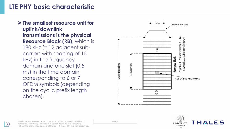
The smallest resource unit for
uplink/downlink
transmissions is the physical
Resource Block (RB), which is 180 kHz (= 12 adjacent sub-
carriers with spacing of 15
kHz) in the frequency
domain and one slot (0.5
ms) in the time domain,
corresponding to 6 or 7
OFDM symbols (depending
on the cyclic prefix length
chosen).
LTE PHY basic characteristic
This document may not be reproduced, modified, adapted, published,
translated, in any way, in whole or in part or disclosed to a third party
without the prior written consent of Thales - © Thales 2014 All rights reserved. 34
OPEN
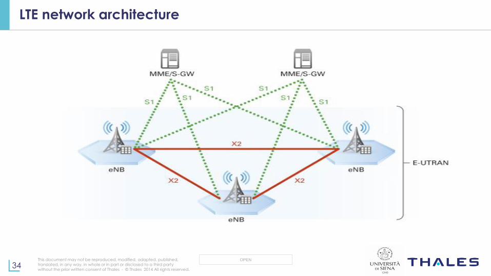
LTE network architecture

This document may not be reproduced, modified, adapted, published,
translated, in any way, in whole or in part or disclosed to a third party
without the prior written consent of Thales - © Thales 2014 All rights reserved. 35
OPEN
▌Guaranteed Bit Rate (GBR)
Dedicated network resources are permanently allocated (for example, by a
CAC function in the eNodeB) when a GBR bearer is established or modified.
▌Non-Guaranteed Bit Rate (Non-GBR)
This bearer does not guarantee any particular bit rate. For these bearers, no
bandwidth resources are permanently allocated. This bearer can be used
for applications such as Web browsing or FTP transfer.
EPS bearers