Embed Size (px)
Citation preview
1
LTE SOW REV2.5 October 1, 2012
1. About this document. This document provides the standard processes and procedures implemented for the AT&T LTE installation. Installation details and specs of the DCx-48-60-RM, DC6-48-60-18, DC6-48-60-18-8F, DC2-48-60-0-9E, FC12-PC6-10E will be provided with each component. The audience for this document includes any and all Black & Veatch personnel and subcontractors who will work on the NY/NJ LTE project. This SOW is applicable to all Black & Veatch Field Installation personnel and sub & 2
nd tier contractors.
For questions or comments about this document's technical content or to request changes to the document contact:
Aldric Gomez [email protected]
2
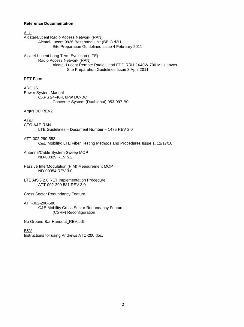
Reference Documentation ALU Alcatel-Lucent Radio Access Network (RAN) Alcatel-Lucent 9926 Baseband Unit (BBU) d2U Site Preparation Guidelines Issue 4 February 2011 Alcatel-Lucent Long Term Evolution (LTE) Radio Access Network (RAN) Alcatel-Lucent Remote Radio Head FDD RRH 2X40W 700 MHz Lower Site Preparation Guidelines Issue 3 April 2011 RET Form ARGUS Power System Manual CXPS 24-48-I, 8kW DC-DC Converter System (Dual Input) 053-997-B0 Argus DC REV2 AT&T CTO A&P RAN LTE Guidelines – Document Number – 1475 REV 2.0 ATT-002-290-553 C&E Mobility: LTE Fiber Testing Methods and Procedures Issue 1, 12/17/10 Antenna/Cable System Sweep MOP ND-00029 REV 5.2 Passive InterModulation (PIM) Measurement MOP ND-00354 REV 3.0 LTE AISG 2.0 RET Implementation Procedure ATT-002-290-581 REV 3.0 Cross Sector Redundancy Feature ATT-002-290-580 C&E Mobility Cross Sector Redundancy Feature (CSRF) Reconfiguration No Ground Bar Handout_REV.pdf B&V Instructions for using Andrews ATC-200 doc.
3
Required Tool List - JDSU Fiber test kit as described in the AT&T Fiber Test MOP
- PIM test equipment as described in the AT&T PIM Test MOP
- Anritsu Sweep Tester
- Digital Volt Multi Meter
- Digital Smart Level
- Compass
- Climbing Gear
- Flush cuts
- Standard Civil tools and materials for the installation of conduit, flex-conduit, H-frames, Telco boxes, etc.
Standard Operating Procedure for all Work Scopes Upon arrival to site location, before entering the site compound or opening any equipment, call the NFSD AND C4E to Status the full site for any alarms and log them. If any are Service Impacting Alarms, call your supervisor immediately and do not enter the location until you are directed to so by B&V. 781-236-3500 Non-Service affecting MOPs must be submitted for all work performed unless the work is service affecting i.e. antenna swaps, DC converter installations; in which case a service affecting MOP must be submitted 48 hours in advance and approved. Contact Sarah Fucci for all MOPs. [email protected] 913-458-1804 201-417-0571 (cell) **IMPORTANT** An alarm check must be called in after completion of any work taking place in the Power Plant and Telco Box to ensure the site is alarm free and taking calls even if crews are still present performing work. **IMPORTANT** Antenna swaps to the existing system (GSM/UMTS) must be reported to the FCM assigned to the site the day of the swap. B&V will notify AT&T to monitor the site performance. If the site is negatively impacted the GC is required to remobilize immediately to trouble shoot.
4
MOP flow and Process
Prior to visiting an AT&T cell site, Contractors performing any Service Affecting / Impacting or Non-Service Affecting / Impacting scopes of work are required to have an approved AT&T Method of Procedure (MOP) number.
All MOPs need to be submitted a minimum of 48 hours prior to the work commencing. The AT&T Market Managers need this time to review for conflicts and other issues. We have to be conscientious of this time line so that we have a manageable work flow.
MOP dates should not overlap. Check the latest version of Swifttrac to see what MOPs are already open for each site. Duplicate or overlapping dates on your requests will cause delays. If you need to be added to the Swifttrac distribution list please let you B&V point of contact know and we will submit that request.
Once on an AT&T cell site – but prior to performing any work, All Sub-Contractors must also call into the AT&T's National Field Support Desk (NFSD) for all scopes of work. If the Sub-Contractor is performing SERVICE affecting / impacting scopes of work they will then be directed to call the NFSD with a provided equipment in maintenance (EIM) number correlating to a network impacting event.
The NFSD operates 24/7 (except for Sunday maintenance window) and can be contacted by calling 1-866-539-1483.
Once work at an AT&T cell site has been completed, all Contractors must contact the NFSD to confirm site operations have been restored to their original condition or better. (This means that the Contractor must resolve any alarms or request assistance to resolve any alarms.)
Should ALU have an issue during Integration you may be requested to mobilize and get a crew out to the site
ASAP. These sites may qualify for an emergency MOP, so you can address the issue the same day you get
notified.
For Pre Integration Alarms (614-718-6400 opt #1) you will need to contact the ALU RITC to troubleshoot with.
They will handle all issues that have prevented the site from getting integrated and any external alarm testing.
RITC will perform RF tests to ensure RRH are working correctly. If external alarm testing is requested you will
need to test out ALL external alarms on site to get them closed out. You MUST have the RITC engineer issue an
internal completion report to his team, if not another site visit will be needed to retest the alarms.
For Post Integration Alarms (614-718-6400 opt#2) you will need to contact the ALU OSC. They will be able to
run RF tests and assist you in high level troubleshooting the site.
Please make sure that your crew is making notes on whom they speak to at ALU and they should be taking pre
and post photos with each visit.
5
Standard Requirements for all Work Scopes All work must be in compliance with AT&T’s ND-51 audit form. Pre Construction Photos Take site photos prior to performing any work. Document the existing condition and document the post construction condition. These photos may be used to determine responsibility should the site be negatively impacted. i.e. open cabinets, broken locks, garbage left behind, roof damage etc. -Report damages, theft and any other pertinent issues immediately to your FCM. Labeling Refer to AT&T’s document LTE Guidelines CTO 1475 REV 2.0 *Note the inconsistency on page 22 where C-2 & A2 land in the squid; C-2 & A-2 should actually be swapped in the documentation. The labeling on the squid itself is correct and should be followed. All labels must be made with a P-Touch label maker. Indoor ground leads must be labeled per the component grounded- affixed with a fiber tag on both sides.
DC6 - DC6
DC Converter – DC/DC
Fiber Management Box – FMB
DC2 – DC2
Remote Radio Head (700 MHz) – 700Mhz RRH
Remote Radio Head (AWS) – AWS RRH
FIF RACK The DC breaker positions will be labeled with P-touch labels.
DC /DC – A
DC/DC - B
RRH Alpha 700MHz – RRH A 700MHz
RRH Alpha AWS – RRH A AWS
RRH Beta 700 MHz – RRH B 700MHz
RRH Beta AWS – RRH B AWS
RRH Gamma 700MHz – RRH G 700MHz
RRH Gamma AWS – RRH G AWS
BBU - BBU Note**Outdoor DC6 – affix color code tape directly to the DC leads. Alpha (green), Beta (blue) Gamma (white). 700 MHz (1 stripe), AWS (2 stripes). This will be in addition to the yellow stripe(s) identifying trunk cable 1 and 2. Coax color code is as follows:
Alpha (green single strip) 700Mhz 1, 3, 5 etc. as necessary; AWS 2, 4, 6 etc. as necessary
Beta ( blue single strip) 700Mhz 1, 3, 5 etc. as necessary; AWS 2, 4, 6 etc. as necessary
Gamma (white single strip) 700Mhz 1, 3, 5 etc. as necessary; AWS 2, 4, 6 etc. as necessary LTE coax will also have (1) strip of magenta affixed furthest from the connector. LTE GPS antenna coax will be labeled w/ 1 magenta stripe.
6
Fiber jumpers color code is as follows:
Alpha (green single strip) 700Mhz 1; AWS 2
Beta (blue single strip) 700Mhz 1; AWS 2
Gamma (white single strip) 700Mhz 1; AWS 2 Color code will be affixed to the black jacketing of the fiber cable. DC jumper color code is as follows:
Alpha (green single strip) 700Mhz 1; AWS 2
Beta (blue single strip) 700Mhz 1; AWS 2
Gamma (white single strip) 700Mhz 1; AWS 2 DC trunk color code is as follows:
700Mhz (single yellow strip) affixed to the jacketing
AWS (two yellow strips) affixed to the jacketing.
Refer to AT&T doc 1475 for A,B & G color code i.e. racer stripe and sector assignment. Note** It is not necessary to label the fiber trunk. Note** It is not necessary to label the 2” corrugated conduit. DC/Fiber installation & testing
All fiber installed must be tested per the ATT fiber test MOP.
All DC installed must be tested for voltage at the DC2/DC6 (squid).
Photo of volt meter DC reading required with a range of -36V to -72V. Commscope/Rosenberger DC Cable Refer to AT&T’s document LTE Guidelines CTO 1475 REV 2.0
Commscope/Rosenberger cable must be installed per manufacturers’ recommendation.
Fiber for AWS from the DC2/DC6 Squid will not be installed or released at this time
Cable gauge required is determined by the length of the run. 12 gauge wire – 0’ to 50’ 10 gauge wire – 51’ to 150’ 8 gauge wire – 151’ and up
DC trunk cable will be stripped back 6” to 8” from the lug to provide a neat appearance where the cabling fans out. The stripped back cabling will be finished off with black heat shrink.
DC jumpers will be stripped back 6” to 8” from the lug to provide a neat appearance where the cabling fans out. The stripped back cabling will be finished off with black heat shrink.
The DC cable drain wire must be grounded at one end only. The other end will be snipped flush with the jacketing at the point the cable is stripped and concealed beneath the black heat shrink.
Exposed DC drain wire must have clear heat shrink installed on indoor applications.
DC trunk cable will be used for the DC path from the -48 DC Power Source to DC6. Note** 12 gauge wire will be used from DC2 to RRH and/or DC6 (squid) to RRH regardless of cable length from DC6 (base station unit) to DC2 and/or DC6 (squid) unless 12 AWG is used for that run then the total run from DC/DC to RRH must be calculated and chart above used. Note**The FC12, DC6 (all models) are equipped with a ground buss.
DC cable must be secured w/ 9 ply wax string (indoor) >every 3’
All tie points - exit and entry points require (2) wraps of fish paper
7
Commscope/Rosenberger Fiber Refer to AT&T’s document LTE Guidelines CTO 1475 REV 2.0
Rosenberger will be installed per the above referenced document
Rosenberger fiber positions in the FC12 & DC6 (Squid) are as follows: Alpha 700 MHz – position 1 Beta 700MHz – position 5 Gamma 700 MHz – position 9
Fiber jumpers are to be secured with Velcro straps
Fiber for AWS from the DC2/DC6 Squid will not be installed or released at this time
Fiber trunks will be supported with hoist grips at the top of any vertical run Conduit & Pull Point Installation Requirements All conduits installed for B&V must have a pull string Conduits must be:
Installed with sweeping bends; no hard 90’s
Rigid through unprotected paths
Rigid through paths between the DC converter & FMB when equipment type is outdoor
Void of sharp edges
Threaded ends of conduits must have a plastic bushing installed
Properly supported
Grounded (MIGB)- one on each end
Rigid must be used between DC/DC converter, DCG, and FMB (outdoor)
No plastic pull boxes in rigid conduit run Conduits paths with seal tight whips greater than 6’ each require a bonding bushing at each end provided it is per NEC. Seal Tite conduits must be:
3’ maximum
Applicable only at either end of a rigid conduit run Corrugated conduits must be/are:
Minimum 2” diameter
Utilized only in runs that are not subject to damage - i.e. in cable tray
Allowable the entire length of a protected path i.e. inside cable tray/ice bridge with a 15’ variance outside cable tray if terminating into a DC2 or FMB
Properly supported-Support the transitions that are 4’ or greater outside of ice bridge/cable tray
Left with a drip loop and small “weep hole” penetrated at the bottom of vertical run and/or before entering the shelter.
Routed into shelters up to the FIF to provide a clean install through existing ladder rack.
Not stacked more than (2) deep Schedule 40 PVC conduits must be/applicable:
Utilized only in runs that are not subject to damage
Not utilized in cable tray
Installed with expansion joints every 30’
Properly supported
8
Pull points must be:
Installed in conduit runs 100’ or greater
Installed after every 180 degrees of total bend radius
Properly anchored
Water tight
Grounded
No plastic pull boxes allowed in rigid conduit runs Note**LB’s are restricted to horizontal runs only. Cable Tray:
Cable tray may be installed instead of rigid conduit so long as approval is granted from B&V, A&E and Landlord.
Drawings must be redlined to reflect cable tray installation.
If installing corrugated conduit into existing cable tray, the cable tray cover must be replaced in full. If cover screws are missing, it is the responsibility of the LTE GC to prove lest they be held accountable for replacement.
Existing cable tray may have no additional room for fiber & DC runs. In this case the cable tray may be stacked and the cover re-used.
Stacked cable tray must be the same size as the existing.
Newly installed cable tray must be properly bonded & grounded.
Newly installed cable tray must be labeled “Do Not Step”.
Newly installed cable tray must be marked for NYC fire code compliance with orange reflective tape for sites built in the 5 boroughs.
Grounding:
The grounding system will be identified at the time of the Pre Con walk. If the system is missing, B&V will notify AT&T; request direction.
GC will notify B&V CM of missing ground system “post” Pre Con Walk.
LTE grounding will be installed per the “No Ground bar Handout_REV.pdf” for ground level work of outdoor sites only. Tower & shelter grounding to be installed as per usual.
The new ground bar must allow for 50% growth. A 9-hole ground bar at each sector is recommended.
Raycap components will be grounded with the OEM lugs.
New hatch plates must be grounded –(1) port = 2 grounds; (2) or more ports = 4 grounds All metallic conduits must be grounded per NEC and marked for NYC fire code compliance within the 5 boroughs. Component ground wire gauges:
DC2 - #2 green
DC6 (squid) - #2 green
DC6 (outdoor base station unit) - #6 or #2 green
DC 6 (indoor base station unit) - #6 or #2 green
DC converter - #6 to the chassis, #2 green to the converter (indoor), #2 tin to the converter (outdoor)
“H” frame - #2 tin (1 per H frame required)
Fiber Management Box - #2 tin
Conduits where required - #6 green
FC12 - #2 Green
FIF Rack - #2 green

9
**Note The OEM lug for the Raycap components match the wire size of the first listed wire gauge above. It is up to the GC’s discretion to use a larger wire size (listed 2nd above) to relive the amount of different wire gauges required on site. However, if the larger wire gauge is used, the OEM lugs must be swapped out for lug types with an inspection hole per AT&T standard. Grounds must be/have:
Oriented for proper drainage (flow)
Void of kinks & tight bends
Void of shiners
Installed with lugs that have inspection windows (component OEM lug exception)
Copper visible at the inspection window to ensure complete insertion of the wire into the lug
2 hole deep barrel lugs
Crimped minimum of two times, max of 4
3/8” SS hardware >No Zinc
Installed with black heat shrink (outdoors)
Installed with clear heat shrink (indoors)
NO-OX applied between lug and attachment
Attachment point cleaned to bare metal-copper shined
Labeled with fiber tags and P-touch labels per labeling section of this document
10
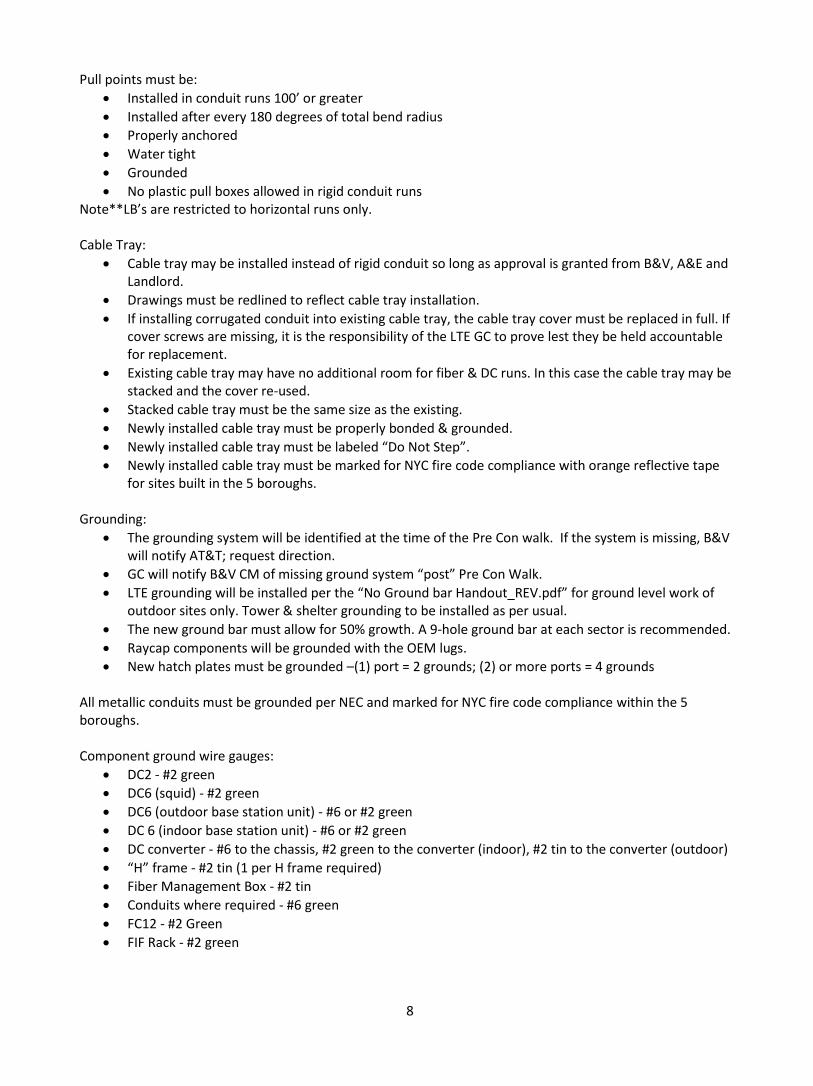
TE-21/41 Power Plant
If the TE-21/41 penetration panel at the rear of the unit is at capacity, the side of the cabinet can be used. Keep penetrations into the cabinet isolated to the areas shown below.
TE-41 Note** The TE/41 indoor unit comes with -48VDC power supply built in. Outdoor unit does not.
11
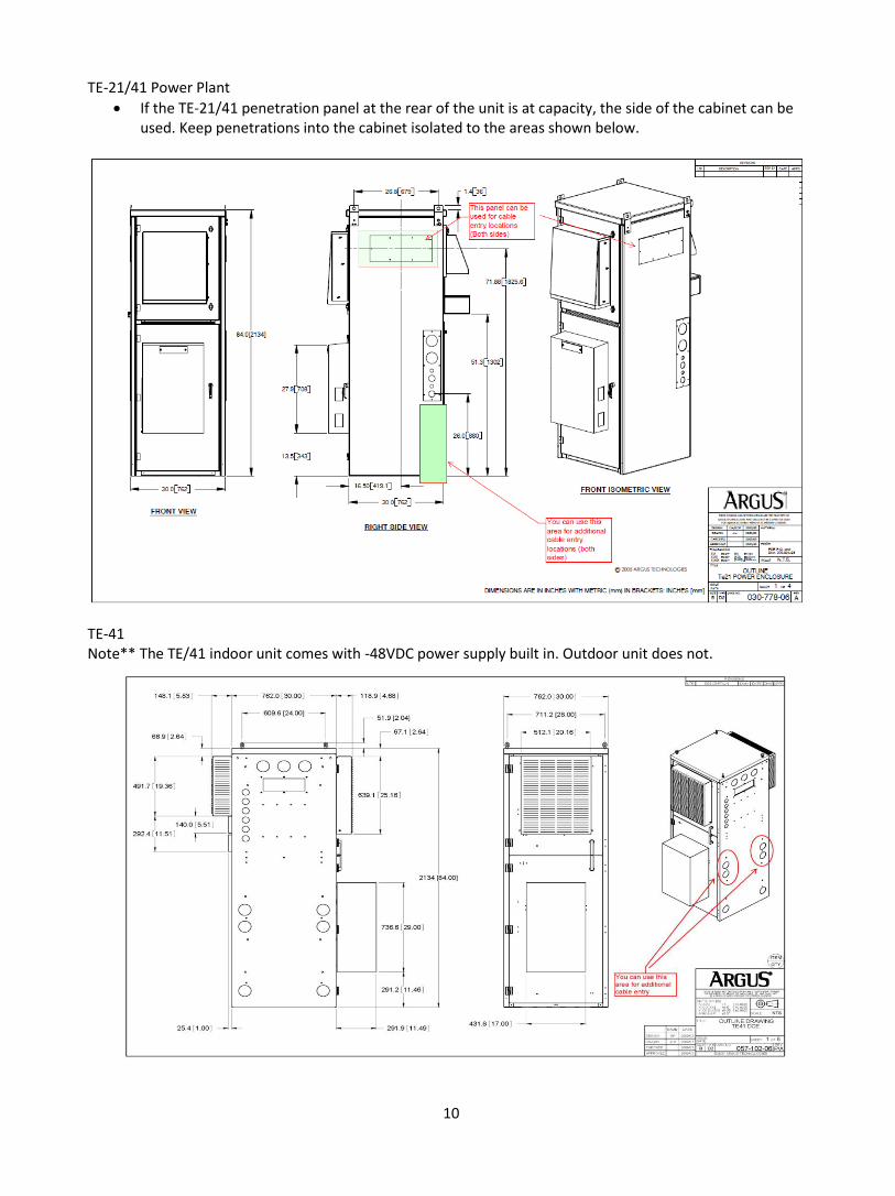
DC Converter:
The DC converter will be installed as follows for outdoor applications: o First Option for installation:
Install the DC to DC converter in the ancillary equipment area (lower half) of the Argus Te21 or Te41
o Second Option for installation: If equipment installed in the ancillary area of the Te21/Te41 is NOT IN USE, propose the
de-installation of the equipment. These materials need to be removed, boxed with mounting hardware and any accessible cabling. Asset tag number(s) and FA location to be legibly written on the outside of the box and returned to the NYC/NNJ CSSL in Carlstadt NJ.
o Third Option for installation: There is room for installation but components need to be consolidated and moved to allow
for the DC to DC converter to fit. Consolidate the equipment into proper positions allowing for air flow per the manufacture equipment specs. If you need specs for certain pieces of equipment please indentify what information is need to B&V and we will provide.
o Fourth Option for installation: There is no room for installation of DC to DC converter in the ancillary space of the
Te21/Te41 but the site has a Te20B cabinet. Remove the top two strings of batteries and the battery tray in the Te21/Te41 to install the DC to DC converter.
o Fifth Option for installation: Last option is to install the DC converter in the NID Purcell. See below.
12
DC converter continued….
The DC converter will be installed in a 19” or 23” rack for indoor applications (Legacy Argus sites).
DC converter requires (4) 4/0 cables. Wire will be Telco Flex IV or KS24194®L4.
Gray cable only will be used
+24 VDC is to be color coded red> 2” from lug; 2” wide
Return will not be color coded
Color code must be sealed beneath the clear heat shrink
Lugs will be short barrel on the converter side to accommodate the tight bends necessary.
Clear Heat shrink is required on both ends of the 4/0 and on all DC lugs that land on the -48 VDC power source
DC converter questions will be referred to Argus at 1-800-GO-ARGUS.
(2) Battery strings (1 shelf) can be removed from the TE-21 only if a TE-20 battery cabinet is on site.
If the battery cabinet is not full the batteries from the TE-21 can be relocated to the TE-20.
If the battery cabinet is full the batteries from the TE-21 will be delivered to the AT&T warehouse. Breaker positions-positions will begin at the furthest left position.
Position 1 – 700Mhz Alpha
Position 2 – 700Mhz Beta
Position 3 – 700Mhz Gamma
Position 4 – AWS Alpha
Position 5 – AWS Beta
Position 6 – AWS Gamma
Furthest right position BBU Breaker amperages
RRHs indoor & outdoor – 15amp
BBU indoor – 10amp
BBU outdoor – 100amp Raycap DC6 outdoor unit (non squid)
The side of the DC6 outdoor unit can be penetrated to accommodate conduit path between DC6 & FMB.
The Meyers hub can be re-used to seal the new penetration.
The bottom opening must be Properly Sealed to ensure a NEMA 4 rating.
13
BBU (Indoor unit)
Installation of the BBU & BBU power will be the responsibility of others.
Sub is responsible for providing RRH fiber to the BBU location routed on the left side of the FIF rack.
Sub is responsible for clearing space & marking out the proposed BBU location.
Sub will provide & install plastic FIF rack stand offs with the fiber & DC secured with Velcro straps. Existing stand offs may be utilized. 1” plastic conduit may be used.
BBU (Outdoor unit)
Installation of the BBU will be the responsibility of others.
GC is responsible for providing: o All necessary path to NID Purcell o RRH fiber – to be left coiled in the NID Purcell o BBU DC wire – to be left coied in the NID Purcell – wire will be gray in color: TelcoFlex IV or
KS24194 L4 telecommunications type wiring. -48 lead is to be color coded blue. o (1) #2 tin ground wire with lug crimped – to be left with adequate length to reach the BBU
location. o BBU alarm cable – to be left coiled in the NID Purcell – punched onto a 66 block in the telco
box. **Note: If the fiber path is direct from the FMB to the BBU, then the RRH fiber will be left coiled in the FMB. The General Contractor will leave a whip of ample length to reach the BBU including the connector. The end of the whip intended to be connected to the BBU will be left unconnectorized.
Stand alone BBU locations require a plinth. GC to provide up to (3) [(1) for RRH fiber, (1) for DC, (1) for Alarms] 2” seal tite whips with connectors with enough slack for others to terminate at (3) points on the BBU which are bottom to the left, bottom to the right and left side.
o Concrete pad requires 14” plinth o Elevated steel platform requires a 4” plinth oriented with the extension to the left side
Note** Cable left for others to install must be left with 6’ secure lengths
14
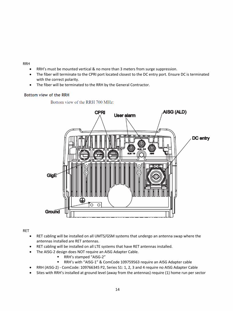
RRH
RRH’s must be mounted vertical & no more than 3 meters from surge suppression.
The fiber will terminate to the CPRI port located closest to the DC entry port. Ensure DC is terminated with the correct polarity.
The fiber will be terminated to the RRH by the General Contractor.
RET
RET cabling will be installed on all UMTS/GSM systems that undergo an antenna swap where the antennas installed are RET antennas.
RET cabling will be installed on all LTE systems that have RET antennas installed.
The AISG-2 design does NOT require an AISG Adapter Cable. RRH’s stamped “AISG-2” RRH’s with “AISG-1” & ComCode 109759563 require an AISG Adapter cable
RRH (AISG-2) - ComCode: 109766345 P2, Series S1: 1, 2, 3 and 4 require no AISG Adapter Cable
Sites with RRH’s installed at ground level (away from the antennas) require (1) home run per sector
15
Azimuths
Azimuths must be set per the proposed value indicated on the latest RFDS.
The azimuths will be set with use of maps, landmarks and compass.
The azimuths must be within 3 degrees of RFDS “proposed” and/or redlines.
All antennas within a sector must be plumb and facing the same direction. Sweeps
LTE jumpers and antennas will be swept per the ATT sweep MOP.
GSM systems require pre/post sweeps if performing an antenna swap.
The GSM system will be left “equal to” or “better than” the pre sweeps.
Sites that incur new sector installations require full sweeps per the ATT sweep MOP.
GPS coax sweeps are not to be executed with GPS antenna installed. Sweep into load. Alarming – See alarming work scope
The DC6 & DC/DC converter will be alarmed via separate CAT 5 cables.
The DC2 will be alarmed via an AT&T provided cable which will connect to the RRH of the associated sector.
The DC6 Squid will be alarmed via an AT&T provided cable which will connect to the RRH of the Alpha sector. Variance to this directive must be approved by the FCM.
These components will be alarmed via the Normally Closed and Common contacts. Civil
All building penetrations will be sealed water tight.
Penetrations will be fire-stopped where applicable. (Fire rated 200 only)
Conduit runs through buildings and building penetrations must be rigid. FIF Rack
If the existing rack lacks space for the DC6, DC Converter & BBU, a new 23” rack provided by AT&T must be installed.
The rack must be properly anchored, leveled, braced, & grounded.
Placement must allow front and back accessibility. ** Note: Do not power the FIF Rack. GPS Installation
The GPS antenna is provided with the Remote Radio Heads.
The GPS antenna will be installed at least 10’ from any other antenna including the existing GPS antenna.
GPS must not be in the beam path of any TX antenna.
All ½” coaxial cable installed will be sweep tested.
Sub must confirm location of GPS antenna is good by use of a hand held GPS(Garmin GPS map 78 or like)
Indoor site types
The DIN to DIN GPS surge arrestor will be installed at the hatch plate.
The surge arrestor must be mounted and secured to a bus bar or other rigid support and grounded. It must not be left free hanging.
The DIN to N surge arrestor will be installed directly onto the side of the FIF rack.
ALU to make final connection from N type surge to BBU.
The Lucent GPS cable from the BBU is 2,000mm.
16
Outdoor site types
(1) DIN to DIN surge arrestor will be installed at the “H” frame.
(1) DIN to DIN surge arrestor that is intended to be installed onto the side of the BBU enclosure will be performed by ALU. Leave this surge arrestor in the NID Purcell.
Install (2) jumpers – GPS antenna to surge arrestor; surge arrestor to primary surge arrestor location (BBU grounding point). Provide appropriate length for connection to the surge which mounts onto the lower side of the BBU.
Leave the coax weather sealed with tape and bag.
Leave appropriate length of GPS coax for others to install between primary surge and DIN female connector at side of BBU.
Coax must be grounded.
Mast pipe must be grounded (do not ground to ice-bridge). Cross Sector Redundancy – LTE only
Is to be implemented on Wave 1B, 1BX & 3 tower sites only where the RRH’s are mounted on the top of the tower at the same RAD center.
Is to be implemented on any site in which the maximum jumper length does not exceed 35’ dressed in and properly secured.
RF jumper lengths shall not exceed 9’ in difference across all sectors. Sector Adds/Sector relocation/Azimuth changes
All prep work can be performed without additional support.
RF cabling & DC cabling (DC if new cabinet is to be installed) will be handed off at the Nokia and UMTS cabinet locations. Connections will be completed by OEM.
Azimuth changes must be reported to the FCM as soon as they are set. Antenna Swaps
The FCM must be notified the day antenna swaps are ongoing by site and sector. This direction is required for UMTS/GSM technologies.
Serial and part numbers of antennas, diplexers & TMAs removed from a site must be reported onto an AMF form at the time they are removed and submitted to the FCM.
The antennas will be properly disposed of depending on the antenna make & model. Andrews products i.e. antennas, TMAs, diplexers, PDU’s & Bias T’s will be returned to Talley warehouse.
Existing jumpers will be-reused to make connections from single band (or other) antennas to the new quad port antenna (most commonly) unless the sweep is failing. Notify FCM for direction on how to proceed.
The feeder line/jumper connection should remain, if possible untouched.
Relocated jumpers must be properly supported.-Every 18”
Field CM’s must be made aware if existing jumpers require replacement prior to doing so.
17
Construction Milestones
Milestone 95 to 103 Raycap surge arrestor installation Rosenberger fiber & DC installation RRH frames installation Grounding Associated civil work needed to accomplish the above
Milestone 103 to 106 Lines & Antenna installation ALU equipment installation DC converter installation Fiber & DC complete installation to ALU & Argus components Grounding GPS antenna installation Fiber & PIM test Close Out Documentation submitted to FCM
Close Out Package
Close out packages are due 24 hours post physical construction completion.
Close out packages include: Signed CD Redlines in .pdf Signed RFDS Redlines in .pdf Tape drop form Sweep tests in .pdf Sweep test in DAT Fiber tests in .pdf PIM tests in .pdf Photos accompanied by the photo checklist AMF form RET form Job Completion Notice
Site Design will be verified during the Pre Construction Walk

18
AT&T Supplied Materials
DC/DC Converter o (TBD) 10 amp breakers (indoor BBU) o (TBD) 15 amp breakers (RRH) o (TBD) 100 amp breaker (outdoor BBU)
BBU’s
RRH’s
ALU kits (see power point presentations 700 RRH PARTS V1, ID BBU PARTS V2 & OD BBU PARTS V1)
23” racks
RX-AIT
MCPA and bricks
Power Plant **IMPORTANT** ALU equipment will be delivered to site by Ridge. The GC will receive a packing list and are required to check it for accuracy upon arrival to site. GC will be held responsible for any missing equipment once signed. Notify the FCM of inaccurate equipment orders.
B&V Supplied Materials Rosenberger and/or Commscope
DC Trunk cabling – 2 required when installed
Fiber Trunk Cabling – 1 required when installed
DC Jumper Cabling – 2 required per sector
Fiber Jumper Cabling – 2 required per sector Raycap
DC6 surge arrestor base station unit indoor – 1 required for indoor site types
DC6 surge arrestor base station unit outdoor – 1 required for outdoor site types
DC6 surge/distribution box (squid) – 1 required for tower sites
DC2 surge arrestor – 1 required per sector rooftop site types
FC12 distribution box – 1 required when trunk cable installed rooftop site types Fiber Management Box 250 amp DC breakers (Argus & Tyco) Breaker adaptors (Argus & Tyco) Tyco breaker shelves Antennas Coax feeder cable, connectors & associated materials TMA/MHA/diplexers **IMPORTANT** Materials must be inventoried against the BOM upon receipt. Notify your FCM of any material shortages within 24 and copy Robin Rosario. It is the GC’s responsibility to purchase additional material if reported as a shortage after 24 hours of receipt. Replacement material will not be issued until the originally released materials are returned. Surplus materials including DC cable must be returned to the Talley Warehouse. General Contractors will be back charged for shortages and/or lost material identified during true up.
19
LTE ROOFTOP SITE SOW
1. DC CONVERTER - Install DC/DC converter. SA MOP Required. a. Install the DC converter into the TE-21. Shifting of E-911 components/Ethernet components/
(2) battery strings (1 shelf) may be necessary to provide adequate clearance. GC is to inform B&V prior to performing this SOW as well as C4E.
b. Removed batteries must be relocated to the TE-20 unless it is full. In this case, the batteries must be returned to the AT&T warehouse. (only remove if TE-20 is present as previously instructed)
c. Install the DC converter per manufacturer instructions.
d. Minimum of 8 rack mounting screw positions of the brackets must be utilized.
**Note**Indoor site type – The DC converter will be installed in the 19”/23” rack. Shifting of existing rack mounted components may be necessary. Standard procedures apply. The converter will be grounded to the shelter ground bar; not the FIF rack bar. Chassis will be grounded at the FIF rack bar.
2. Power the DC/DC converter. a. Dress and secure (4) 4/0 cables from the power plant breaker distribution to the DC/DC
converter. Cables must be properly laced with wax string and fish paper.
b. DC lugs will be crimped 2X with proper crimpers. Install clear heat shrink onto each lug.
c. “Each” hardware set is: 2 flat washers, 2 lock washer and 2 nuts. (Exception is the TE-41 which comes with self tapping nuts in which case flat and locks are not necessary).
d. Label the breaker positions “DC/DC - A” & “DC/DC - B” on the schedule.
e. Ground the DC/DC Converter to the equipment ground system. Grounding to the “rack” is the last option and must be approved by the FCM. Paint or galvanization must be removed prior to connection.
f. Ground per manufacturer instruction.
g. Apply NO-OX to all ground connections. Note**Indoor site type – The DC cabling will be installed on “J” hooks separating them from the communications cables on the existing ladder rack. Required spacing is 12”-18”
3. SUPPORT FRAME - Install a unistrut support frame “BTS Equipment Location”. a. Extend the existing “H” frame to accommodate the DC6 & Fiber Management box.
b. If the existing frame cannot be extended, install and ground a new “H” frame.
c. Ensure the unistrut has no sharp edges and that ends have safety caps.
d. All cut edges of unistrut must be filed and sprayed with cold galve compound.
e. The unistrut frame must be grounded as per standard requirements for all work scopes.
f. Unistrut must be galvanized.
g. Hardware must be stainless steel or galvanized but not mixed.
20
4. DC6 SURGE ARRESTOR (BASE STATION UNIT) - Install the DC6 Surge arrestor. a. Install the DC6 outdoor unit as close to the Power Plant & BBU as possible. Secure the unit to
the “H” frame behind the equipment on the exterior of the hand rail/existing frame.
b. Install per manufacturer instruction.
c. Ensure proper orientation to prevent water ingress including silicone sealing all openings.
d. Ground the DC6 unit to the MGB using #6 or #2 green and (2) hole deep barrel lugs with proper hardware (flat washers & lock washers) with minimum 2 crimps. Black heat shrink required.
e. Apply NO-OX to ground connections.
f. Remove all metal shavings & wire clippings.
Note**Indoor site type – The DC6 will be installed in the 19”/23” rack. Shifting of existing rack mounted components may be necessary. Standard procedures apply. The converter will be grounded to the shelter ground bar; not the FIF rack bar.
5. FIBER MANAGEMENT BOX (FMB) - Install the Fiber Management Box. a. Install the fiber management box per drawings; for best results as close to the DC6 as possible.
The fiber management box will be used to coil and store excess fiber. More than (1) FMB may be necessary and will be handled on a site by site basis.
b. Secure the fiber management box to the “H” frame behind the equipment on the exterior of the hand rail/existing frame.
c. Ensure proper orientation to prevent water ingress including silicone sealing all openings.
d. Ground the fiber management box using #2 tin and (2) hole deep barrel lugs with proper hardware (flat washers & lock washers) with minimum 2 crimps.
e. Apply NO-OX to ground connections.
f. Remove all metal shavings & wire clippings.
Note**Indoor site type – Excess fiber can be lost in the Fiber Storage tray. However, the fiber must be coiled neatly and secured with velcro straps.
6. RRH MOUNT FRAMES - Install a Sector Unistrut support frame. a. Install a unistrut support frame at each sector. Location will be determined at the time of the
pre construction walk but will usually be installed to a parapet wall or sled or wall mount.
b. The unistrut support frame must accommodate 2 RRHs and 1 DC2 (16” of frame from the 700 RRH). Install the H frame with spacing as per the Lucent requirements.
c. Ensure the frame is grounded.
7. DC2 SURGE ARRESTORS - Install the DC2 Surge arrestors (1) per sector. a. Install the DC2 unit onto the unistrut support frame at each sector.
b. Install the DC2 per manufacturer instructions.
c. Ensure proper orientation to prevent water ingress including silicone sealing all openings.
d. Ground the DC2 unit using #2 green and (2) hole deep barrel lugs with proper hardware (flat washers & lock washers) with minimum 2 crimps.
e. Apply NO-OX to ground connections.
21
8. ROSENBERGER DC CABLING - Install DC cables and 2” rigid conduit from the DC converter to DC6 outdoor unit.
a. Install 2” rigid conduit.
b. Support conduit as required.
c. Conduit supports must be stainless steel.
d. Ensure all conduit connections are tight.
e. Seal tight whips no greater than 3’ in length may be used to connect conduit paths to equipment enclosures
f. Install DC cables (2 trunks) from the DC converter to the DC6 surge arrestor and terminate.
g. Ground the DC cable to the DC6 bus bar.
h. The 700 MHz circuits will terminate per AT&T document CTO 1475 REV2.0.
i. The AWS MHz circuits will terminate per AT&T document CTO 1475 REV 2.0.
9. Install DC cables and 2” rigid conduit from the DC6 outdoor unit to the fiber management box. a. Install 2” rigid conduit.
b. Support conduit as necessary.
c. Conduit supports must be stainless steel.
d. Ensure all conduit connections are tight.
e. Ensure the conduit penetrations are sealed.
f. Install DC cables from the DC6 surge arrestor through the fiber management box.
g. The 700 MHz circuits will terminate per AT&T document CTO 1475 2.0.
h. The AWS MHz circuits will terminate per AT&T document CTO 1475 2.0.
i. Shiners are unacceptable.
j. DC and fiber will run in the same conduit from this point and extend to the DC2s at each sector.
10. ROSENBERGER FIBER CABLING - Install DC & fiber cables in 2” conduit from the fiber management box to the DC2 unit. Each run is a bundle of (2) DC circuits and (2) fiber jumpers. One run per sector.
a. Install corrugated conduit into the coax cable tray. Cable tray may be at capacity in which case additional cable tray will need modification. Determined during pre con.
b. New cable tray additions including stacked sections must be grounded per standard.
c. The cable tray cover must be replaced in full. If cover screws are missing, it is the responsibility of the LTE GC to prove lest they be held accountable for replacement.
d. If any part of the path to the sectors is “shared”, more than one sectors’ DC & fiber may occupy the same conduit to conserve space however, the divider/combiner section of the run must ensure that the DC & fiber circuits will incur no damage and that new circuits can be pulled end to end. A “Y” connector is required.
**Note** this is not recommended and should be considered as a last option.
e. The 700 MHz circuits will terminate to “A”, the AWS MHz circuits will terminate to “B”.
f. Excess fiber will coil then pass through to the RRH.
g. Document the DC voltage is within the specified range at the DC2/DC6 (squid) end with a photo. The photo must be submitted with the COP.
h. Ensure the breakers are locked out after the voltage test.
22
11. Note** Conduit is 2” corrugated plastic tube which is allowable in lengths that are not subject to damage i.e. in cable tray or under “ice bridge”. In cases where runs are not encased in cable tray, DC & fiber runs will be installed in rigid conduit or schedule 40 PVC as described in the “Standard Requirements for all work scopes” section of this document. To be determined during pre construction walk.
12. REMOTE RADIO HEADS - Install the RRHs per the ALU Site_Prep 9442 RRH 700MHz_15 5 Lower Band
v08.pdf. a. Install the RRHs per manufacturer instruction.
b. The RRH must be installed within 6’ of the DC2 on the same support frame. The frame must be sized to house future AWS RRH’s.
c. Extend (1) DC circuit to the 700MHz RRH in 1” seal tite conduit.
d. Extend (1) fiber jumper & alarm cable together within (1) 1” liquid tite conduit (sites with DC6 Squids as surge suppression will have an alarm cable installed to the Alpha sector RRH only). Variance to this directive must be approved by the FCM.
e. Ensure the liquid tite is cut back 8” from the rubber grommet that comes with the bullets.
f. Hold the fiber below the grommet with minimal tension while tightening the grommet to ensure the fiber does not kink inside the bullet.
g. Leave the AWS fiber & DC circuit coiled in the DC2 for future installation.
h. Ensure there is room for the 2nd future RRH. i. RRH requires 4” side and 12” bottom clearance minimum, 7” side clearance if wall attached.
(See ATT doc 1475)
13. GPS – Install the 1/2” GPS RF cable from the GPS installation location to the BBU location. a. Outdoor equipment sites will have the surge arrestor affixed to the side of the BBU cabinet by
ALU.
14. BBU – BBU to be installed by others. a. Install path, power & ground as described in the standard requirements for all work scopes
section of this document. b. Provide pull string in fiber path from SIAD to the NID Purcell fiber path, pull string to be
installed in all LTE Conduits.
15. ANTENNAS - Install antennas per RFDS. a. Orient the LTE azimuths per the latest RFDS. The GSM & UMTS antennas azimuths will be re-
oriented to match.
b. Site specific RF work scope will be determined by the RF design captured on the latest RFDS. Pay extra attention to RFDS Revision numbers.
c. A service affecting MOP must be submitted prior to performing RF work that affects the existing AT&T network i.e. changing azimuths, opening connections, antenna swaps etc.
d. Unused ports must have terminators installed and sealed with heat shrink.
e. Install & ground new antenna mount per drawings & industry standards. All pipes with antennas installed for the LTE project require to be grounded including existing pipes.
f. Tape drop, tape drop form and photo of newly installed antenna and/or relocated antennae are required within 24 hours of installation.
g. Document the mechanical tilt of the antenna with a photo. The mechanical tilt must be within 1.0 degree of the RFDS.
h. Perform sweeps and PIM tests per AT&T MOP.
23
16. 14. Clean up the site.
17. Complete and apply B&V log book sticker.
18. Take pictures of all work performed. Completion photos of each wave of construction are due no later than 2 days post completion.
19. Secure the site.
20. Call the MNOC or B&V Site Status Tech to Status the full site for any alarms and log them. If any are additional from the pre-status they need to be resolved before leaving the site. If any are Service Impacting, report them to B&V immediately and attempt to restore the site.
24
ROOFTOP TRUNK CABLE & FC12 INSTALLATION SOW
1. FC12 SUPPORT FRAME - Install a support frame for the FC12.
a. Install a unistrut support frame to support the FC12 & in some cases the FMB. Location will be determined at the time of the pre construction walk but will usually be installed at the “split point” of the cable run. It is recommended to install the frame onto a custom sled that stands above the cable tray to allow the conduits to be bottom fed into the FC12 & FMB.
b. Ensure the frame can hold the FC12 and an FMB back to back.
c. Install a (9) hole ground bar with isolators. Tie the ground to the existing system via #2 tin ground wire.
d. Ground the frame to the newly installed bar.
2. FC12 - Install the FC12 distribution box. a. Install a unistrut support frame for the FC12.
b. Install per manufacturer instruction.
c. Ensure proper orientation to prevent water ingress including silicone sealing any openings.
d. Ground the FC12 unit to the MGB using #6 green and (2) hole deep barrel lugs with proper hardware (flat washers & lock washers) with minimum 2 crimps. Black heat shrink required.
e. Apply NO-OX to ground connections.
f. Install a 2” conduit path tying the FC12 to the FMB.
3. ROSENBERGER DC TRUNK CABLING - Install (2) DC trunk cables in (1) 2” conduit from the equipment location to the FC12 unit.
a. Conduit type will depend on the site specific conditions and layout.
b. Install (2) DC trunks from the DC Converter through all required components in the path to the FC12.
c. The 700 MHz circuits will terminate per AT&T document CTO 1475 REV2.0.
d. The AWS MHz circuits will terminate per AT&T document CTO 1475 REV2.0.
e. Install (1) 2” conduit per sector from the FC12 to each sectors’ DC2 through which (2) DC circuits can be installed.
4. ROSENBERGER FIBER TRUNK CABLING - Install (1) fiber trunk cable in the (1) 2” conduit referenced above from the equipment location to the FC12.
a. Install (1) fiber trunk from BBU location through all required components in the path to the FC12.
b. The 700 MHz circuits will terminate per AT&T document CTO 1475 REV2.0.
c. The AWS MHz circuits will terminate per AT&T document CTO 1475 REV 2.0.
d. Coil the excess trunk fiber into the FMB.
e. Install (2) fiber jumpers in the conduit referenced above from the FC12 to the DC2’s.
25
TOWER TRUNK CABLE & DC6 (SQUID) INSTALLATION SOW
1. TOWER MOUNTED DC6 (SQUID) - Install the Tower Mounted Distribution box (Squid). a. Install the squid to a pole/T-boom arm using either the mounting brackets provided or chain
mount to the tower. Install the squid close to the Alpha sector.
b. Install per manufacturer instruction.
c. Ensure proper orientation to prevent water ingress including silicone sealing any openings.
d. Install a CAT5 alarm cable from the squid to the Alpha sector RRH (This step will be completed during construction phase 2).
e. Ground the squid unit to the MGB or sector bar using #2 green and (2) hole deep barrel lugs with proper hardware (flat washers & lock washers) with minimum 2 crimps. Black heat shrink required. The squid comes from factory with lug attached.
f. Apply NO-OX to ground connections.
2. ROSENBERGER DC & FIBER TRUNK CABLING - Install (2) DC & (1) fiber trunk cables in 2” conduit from the equipment room to the squid unit.
a. Support conduit every 3’ (horizontal runs).
b. Ensure all conduit connections are tight.
c. Hoist grips for the DC & Fiber trunks must be installed at the exit port to relieve pressure from the squid. A second hoist grip is required at the squid.
d. The conduit must be supported at the top port hole. Install a connector onto the top end of the conduit to ensure a neat & clean appearance.
3. Note** Conduit is 2” corrugated plastic tube which is allowable in lengths that are not subject to damage. This direction may change.
4. ROSENBERGER DC & FIBER JUMPER CABLING - Install DC cabling & fiber cables from the squid to the
RRHs units. a. Install (1) DC & Fiber circuit to the RRH location running free air.
b. Secure with black UV rated zip ties, flush cut all zip ties using “flush cuts”.
c. The rubber gaskets in the squid will have to be removed and slit with a razor knife to slide over the fiber cables if necessary.
5. REMOTE RADIO HEADS – The RRH will be installed per the 418-000-424_700 MHz_15.5 Lower Band RRH.pdf.
a. Install the RRHs per manufacturer instruction.
b. In some cases the RRH will be installed on an “H” frame; in other cases the RRH will be installed on the same antenna mast pipe as the LTE antenna.
c. Extend (1) DC circuit to the 700MHz RRH in 1” seal tight.
d. Extend (1) fiber jumper supported with insulated “P” clips to the 700 MHz RRH.
e. Do not extend the AWS fiber & DC circuit from the Squid at this time.
f. Ensure there is room for the 2nd future RRH.