Embed Size (px)
Citation preview
LTE Backhaul Planning and
Optimization
(Capstone Project 709)
by
Manjeet Kumar A thesis submitted in partial fulfillment of the requirements of the degree of
Master of Science
in
Internetworking Department of Electrical and Computer Engineering
University of Alberta
©Copyright 2017, Manjeet Kumar
LTE Backhaul Planning and Optimization
2
ABSTRACT
In the era of fast paced environment, Technological enhancements and their rapid and
wide applications are having a significant impact on a nation’s traditional skills and ways
of life. With new technology hitting in the market, this is changing the way that how we
are living the life.
Evolution of LTE deployment in telecom made the end user life easier and fast. Initially
people were using wireless telecom for voice services only & with passage of time
customer’s needs increased and voice only was not enough to serve the purpose. Then
evolution of data came in. Enhancing from third generation to the fourth generation, has
accomplished big capacity and high speed of mobile telephone networks as well as high
internet speed without any doubt.
The main objective of this project is, firstly to identify the factors that affect the design of
the wireless access network for LTE and define how to take them into account to achieve
optimally performing and cost-efficient networks. It will present an overall description
for LTE backhaul research, architecture and some parameters to deploy an efficient LTE
network. Secondly after deployment, then the troubleshoot part comes in. In this section,
we will show problem that the network can face while in use and their solution are
explained to enhance the performance of the LTE network.

LTE Backhaul Planning and Optimization
3
Acknowledgement
First and foremost, I would like to thank God for providing me patience and strength to
work on this project. This venture would not have been conceivable without his direction
and support.
It is my privilege to express my sincerest regards to my project mentor, Mr. Juned
Noonari for his significant information sources, capable direction, support, whole-hearted
participation and suggestions throughout the duration of our project. He has incredibly
influenced me and his consistent feedback and direction has encouraged me to complete
the project.
I deeply express my sincere thanks to my program coordinator Mr. Shahnawaz Mir for
encouraging and allowing us to present the project at our department premises for the
partial fulfillment of the requirements of the degree of Master in Science in
Internetworking. I also take this opportunity to thank to Prof. Mike McGregor who
permitted me to proceed with this project in the first place.
On a personal note, I offer my regards to our lecturers who have directly or indirectly
helped my project. I pay my respects and love to my parents and all other family
members and friends for their love and support. Last but not the least I express our
gratitude to University of Alberta to give me this opportunity.
LTE Backhaul Planning and Optimization
4
Table of Content
1. Introduction………………………………………………………………...9 1.1. Background…………………………………………………………………..……...10
1.1.1 1G……………………………………………………………………..……...11
1.1.2 2G………………………………………………………………………….....11
1.1.3 2.5G (GPRS)General Packet Radio ………………………………………....11
1.1.4 2.75G (EDGE)Enhanced Data Rates for GSM Evolution …………………..11
1.1.5 3G ………………………………………………………………………........12
1.2 Related Standards and Industry Forums…………………………………………......12
1.2.1 3GPP ………………………………………………………………………...12
1.2.2 ITU-T SG15………………………………………………………………….13
1.2.3 IEEE 802 …………………………………………………………………….13
1.2.4 IETF ………………………………………………………………………..13
1.2.5 MEF ………………………………………………………………………..13
1.2.6 NGMN ………………………………………………………………………14
1.2.7 BBF ………………………………………………………………………….14
1.2.8 SCF …………………………………………………………………….….14
References:……………………………………………………………………………………15
2. LTE Architecture……………………………………………………………..16 2.1 Below is the explanation for different elements in the architecture……………..…..18
2.1.1 User Equipment (UE) ……………………………………………………….18
2.1.2 eNodeB………………………………………………………………………18
2.1.3 Serving Gateway (S-GW) …………………………………………………...19
2.1.4 Packet Data Network (PDN) Gateway (P-GW) …………………………….19
2.1.5 Home Subscriber Server (HSS) ……………………………………………..19
2.1.6 Mobility Management Entity (MME) ……………………………………….20
2.1.7 Policy Control and Charging Rules Function (PCRF) ………………………21
2.2 The Issues Surrounding LTE………………………………………………………...21
References:……………………………………………………………………………………22
LTE Backhaul Planning and Optimization
5
3. Various LTE backhaul network……………………………………………………...23 3.1 Wireline technologies………………………………………………………………..23
3.1.1 Local Ethernet………………………………………………………………..23
3.1.2 DSL (digital subscriber line) ………………………………………………...23
3.1.3 Fiber……………………………………………………………………..…...24
3.1.4 DOCSIS (data over cable service interface specification) …………………..25
3.2 WIRELESS…………………………………………………………………………..25
3.2.1 POINT TO POINT microwave radio………………………………………...25
3.3 Components of backhaul……………………………………………………………..26
3.3.1 Fiber, copper and microwave………………………………………………...26
3.3.2 Base Stations or eNodeB…………………………………………………….26
3.3.3 Routers……………………………………………………………………….27
3.4 Understand and discuss pros and cons of various backhaul networks……………….27
3.4.1 LOCAL ETHERNET………………………………………………………...27
3.4.2 DSL (digital subscriber line) ………………………………………………...28
3.4.3 FIBER………………………………………………………………………..29
3.4.4 DOCSIS (data over cable service interface specification) …………………..30
3.4.5 POINT TO POINT microwave radio………………………………………...32
References:……………………………………………………………………………………33
4. LTE BACKHAUL PLANINNG……………………………………………...34 4.1 Requirements for LTE……………………………………………………………….34
4.1.2 The primary requirements include below points…………………………….34
4.1.3 Some more below requirements are given below……………………………36
References:……………………………………………………………………………………36
5. Network Topology and Transport Media…………………………………...37 5.1 Access Network Topologies and Media……………………………………………..37
5.2 Aggregation Network Topologies………………………………………………..…..39
References:……………………………………………………………………………………40
6. Backhaul Network Deployment Scenarios…………………………………………41 6.1 Implications to Backhaul Scenarios………………………………………………….41
LTE Backhaul Planning and Optimization
6
6.1.1 Ethernet Services…………………………………………………………….41
6.1.2 Comparison…………………………………………………………………..44
6.2 L3 VPN Service……………………………………………………………………...44
6.2.1 Comparison to L2 Services…………………………………………………..45
6.3 Scenario 1: Ethernet Service in the Access………………………………………….45
6.4 Scenario 2: IP Access………………………………………………………………..46
References:……………………………………………………………………………………47
7. Indoor Coverage Solutions…………………………………………………………….48 7.1 Different types of cells used in the LTE network……………………………………49
7.1.1 Macro………………………………………………………………………...49
7.2 What precisely is a small cell? ………………………………………………………49
7.2.1 Picocells……………………………………………………………………...49
7.2.2 Microcells……………………………………………………………………49
7.3 Comparing Backhaul Links for small Cells…………………………………………50
7.4 Summary and Conclusions for small cells…………………………………………..50
References:……………………………………………………………………………………50
8. Modulation…………………………………………………………………………...........52
References:……………………………………………………………………………………53
9. MIMO…………………………………………………………………………....................54
References:……………………………………………………………………………………54
10. Wireless Cellular Network Dimensioning………………………………………..55 10.1 Planning Procedure…………………………………………………………………55
10.1.1 To make this design work we need below things…………………………..56
10.1.2 Dimensioning……………………………………………………………….57
10.1.3 General wireless cellular network planning process………………………..57
References:……………………………………………………………………………………58
11. LTE Objective………………………………………………………………..59 11.1 The Major objectives are given below……………………………………………...59
11.1.1 LTE Dimensioning Process………………………………………………...59
LTE Backhaul Planning and Optimization
7
11.1.2 Data and Traffic Analysis…………………………………………………..59
11.1.3 Traffic Analysis…………………………………………………………….60
11.1.4 Coverage Planning………………………………………………………….60
11.1.5 Capacity Planning…………………………………………………………..60
11.1.6 Transport Dimensioning……………………………………………………61
References:……………………………………………………………………………………64
12.Carrier aggregation and MBH tiers in LTE ………………………………65 12.1 Carrier Aggregation………………………………………………………………...65
12.1.1 CA Impacts on Backhaul Transport………………………………………..66
12.2 MBH Tiers………………………………………………………………………….66
12.2.1 Simple Tier Mobile Network………………………………………………66
12.3 Backhaul Network Tiers……………………………………………………………67
References:……………………………………………………………………………………68
13. Network Deployment………………………………………………………...69 13.1 LTE Backhaul Network Implementation on the City………………………………69
13.2 Design Examples….………..……………………………………………………....75
13.2.1 Scenario 1: Leased Line…………………………………………………….75
13.2.2 Scenario 2 (Microwave) ……………………………………………………76
References:……………………………………………………………………………………78
14. LTE Network Optimization…………………………………………………79 14.1 Accessibility or CFR (Call Failure Rate) …………………………………………..80
14.1.1 LTE CALL FLOW…………………………………………………………81
14.2 Accessibility Problems……………………………………………………………...81
14.2.1 Accessibility Issues in RRC Phase and Solutions…………………………..81
14.2.2 Accessibility Issues In S1 Phase and Solutions…………………………….82
14.2.3 Accessibility Issues In E-RAB Phase and Solutions……………………….82
14.3 Retainability or CDR (Call Drop Rate) ……………………………………………83
14.3.1 Retainability Issues and Solutions………………………………………….83
14.4 Hand off Failures…………………………………………………………………...84
14.4.1 Mobility: Introduction………………………………………………………84
LTE Backhaul Planning and Optimization
8
14.4.2 Handover……………………………………………………………………84
14.4.4 Mobility Optimization……………………………………………………...85
14.4.5 HO Preparation Fail Troubleshooting and Analysis………………….…….87
14.4.6 HO Execution Fail Troubleshooting and Analysis…………………….…...88
14.4.7 Features that will help in improving the Mobility KPI…….………………92
14.5 Throughput Troubleshooting………………………………………………………93
14.5.1 Downlink Throughput Troubleshooting…………………………………….93
14.5.2 UL TROUBLESHOOT……………………………………………………..98
References:………………………………………………………………………………….100
15. Conclusion ………………………………………………………………….101 List of Acronyms…………………………………………………………………………..102 References:- ………………………………………………………………………………...104
LTE Backhaul Planning and Optimization
9
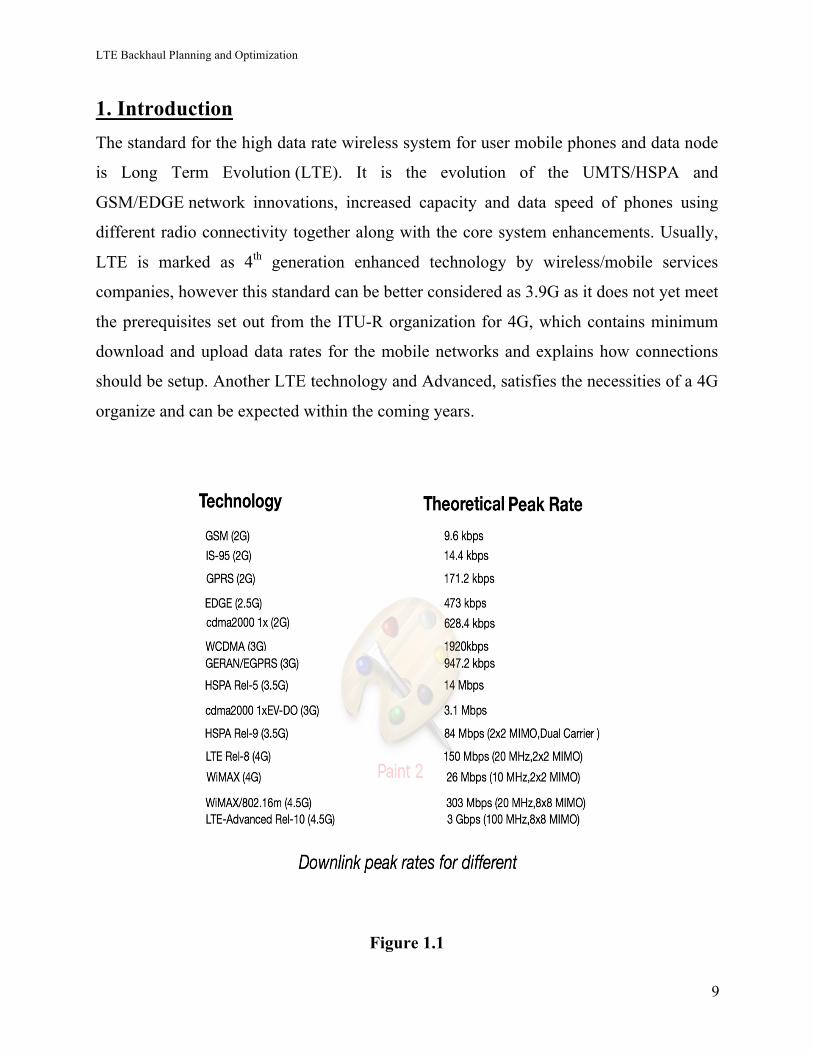
1. Introduction The standard for the high data rate wireless system for user mobile phones and data node
is Long Term Evolution (LTE). It is the evolution of the UMTS/HSPA and
GSM/EDGE network innovations, increased capacity and data speed of phones using
different radio connectivity together along with the core system enhancements. Usually,
LTE is marked as 4th generation enhanced technology by wireless/mobile services
companies, however this standard can be better considered as 3.9G as it does not yet meet
the prerequisites set out from the ITU-R organization for 4G, which contains minimum
download and upload data rates for the mobile networks and explains how connections
should be setup. Another LTE technology and Advanced, satisfies the necessities of a 4G
organize and can be expected within the coming years.
Figure 1.1
LTE Backhaul Planning and Optimization
10
NTT DoCoMo the company of japan, introduced this technology which was started in
2004. Researches started officially in the year 2005 and the first standard was being
concluded in 2008. In Stockholm and Oslo, it was live in 2009 as a type of data link with
a USB modem structure, supported via carrier or operator TeliaSonera. In North America
Metro PCS and Verizon moved to this technology in the year of 2011. At first, operators
for example, Sprint, Verizon, Bell and even Metro PCS, which keep running on CDMA
systems had planned to move up to a rival technology standard known as the UMB, but
now, have chosen to support LTE and LTE-A (LTE Advanced).
All in all, what LTE exactly is described? It depends on GSM or EDGE and UMTS or
HSPA network technologies, and provides an expansion to both the capacity and data
speed using new strategies for modulation. It gives peak download data rates of 150
megabits for every second, transfer data rates of 75Mbps (megabits for per second) and a
data transfer latency of under-five milliseconds. It can manage multi-cast as well and
broadcast the data streams and handle snappy moving cell phones. This has an Evolved
Packet Core (EPC), with the IP-based network design, which allows for consistent
handovers for the voice and data to aged established model cell sites that work on GSM,
UMTS/CDMA2000 standard technology. Likewise, it has the range from 1.4 MHz to 20
MHz spectrum carrier data bandwidth and backings both frequency division
duplexing(FDD) and time-division (TD). So finally, the new design of LTE based
technology means to bring down working expenses alongside with huge overall data rates
and voice bandwidth capacity.
1.1 Background: -
1.1.1 1G (or 1-G) belongs to the 1st generation of the wireless based telephone
technology. These are the analog mobile communication standards which were presented
in the 1980s and proceeded until being replaced by the 2G (2nd generation) digital mobile
communication. The radio signal is the fundamental difference between the two-mobile
network (of different technology means 1G and 2G), utilized by the 1G mobile network
is analog, while 2G system is digital. Although both systems utilize digital radio
LTE Backhaul Planning and Optimization
11
signaling to link the radio sites (which catches to the UE’s) to the remaining telephone
system, during making a call voice is encoded in the digital radio signals in a 2nd
generation while in 1G is generally 150 MHz and more with just modulated to the higher
frequency spectrum.
1.1.2 2G is the second- generation wireless telephone technology. Second- generation
2G mobile telecom systems were commercially implemented on the standard of GSM in
Finland by Radiolinjain 1991. 2G presented data services for mobile, beginning with
SMS instant messages. 2G technologies empowered the various cell phone networks to
give the services for example text messages, media messages, and MMS. Digitally
encrypted message was sent through 2G, which allowing for the transfer of the data in a
manner that only the original recipient can get and can read it.
1.1.3 2.5G (GPRS)General Packet Radio is also known as 2.5G, is utilized to
explain 2G-networks. In addition to the circuit-switched network, it has installed a
packet-switched as well. It uses timeslot bundling for circuit network as well so does not
give very good fast service. The main significant step in the advancement of GSM
systems to 3G happened with General Packet Radio Service (GPRS). CDMA2000
networks comparably developed through the launching of 2.5G. Its approach centered on
the utilization of packet data. It turned on circuits to be utilized more efficiently and
charges need to be metered by the data exchanged.
1.1.4 2.75G (EDGE)Enhanced Data Rates for GSM Evolution With the help of
8PSK, GPRS systems enhanced to the EDGE networks. while the symbol data rate
becomes the equal at 270.833 samples/s, every symbol carried three bits rather than one.
(EDGE), Enhanced GPRS (EGPRS), Enhanced Data rates for GSM Evolution or IMT
Single Carrier (IMT-SC) are old-fashioned technology for digital mobile telephone that
allows enhanced data transmission rates, an expansion on top of the GSM. EDGE was
implemented on the GSM systems starting in 2003—at first by AT&T in the United
States. EDGE is the standardized given by 3GPP as a major aspect of the GSM family
and it was an enhanced version that gives a potential 3-fold increment in the capacity of
GPRS or GSM technologies. The digital service of 2nd generation gave extremely
LTE Backhaul Planning and Optimization
12
valuable features, for example, call forwarding, caller ID, and the short messaging 3G to
3G, the short form of 3G (3rd generation) is the 3rd generation of media
telecommunications technology. 3G discovers application in fixed wireless Internet
accessing, wireless voice telephony, mobile data access, mobile TV and video call.
1.1.5 3G, the 3rd generation of mobile communication technology. This is inspired by a
rule of guidelines taken from cell phones and mobile communications use different
services and systems that comply to the International Mobile Telecommunications (IMT-
2000). 3G found application in wireless voice communication, mobile Internet accessing,
Internet access with fixed wireless, mobile TV and video calls. 3G standard networks
support the services that gives a data exchange rate of minimum at speed of 200 kbit/s.
Later 3G releases, commonly denoted 3.5G and 3.75G, also give mobile broadband using
of a few Mbit per second to cell phones and mobile modems used in laptop and
computers.
This guarantees it can be implemented to wireless voice telecommunication, mobile data
access, mobile Television technologies, fixed wireless Internet access and voice calls. On
approximately every 10th year the new generation is to be launched since 1G systems
were invented in 1981 or 1982.Each and every telecommunication generation is filled
with the new frequency spectrum bands, higher the data rates and non-backward
compatible technology. The initial 3G systems were presented in 1998 and 4G in 2008.
1.2 Related Standards and Industry Forums
In the below segments, the main involved associations and industry forums and their
related details and standards are presented.
1.2.1 3GPP
Third Generation Partnership Program (3GPP) characterizes what transport protocols
might be utilized for the transport interfaces, but the real transport details and standards
are finished by different organizations.
LTE Backhaul Planning and Optimization
13
1.2.2 ITU- T SG15
ITU-T Study Group 15 (systems, advancements and infrastructures for transport, access
and home) has a sub work group called Question 13/15. Address 13/15 (system
synchronization and time distribution execution) contemplates network synchronization
issues related to packet systems with an attention on mobile system needs.
1.2.3 IEEE 802 (Institute of Electrical and Electronics Engineers (IEEE))
Local Area and Metropolitan Area (LAN/MAN) Standardization Committee (IEEE802)
characterizes the physical layer and link layer of systems and gives an entire set of
guidelines for carrying IP. IEEE802.1 working group characterizes "higher" link layer functions for the Ethernet,
e.g. Local Area Network (LAN)/metropolitan area network (MAN) design, and network
management.
IEEE802.3 working group determines physical layer (PHY) (In 7-layer system) and the
media access control (MAC) for conveying Ethernet over wired connections.
1.2.4 IETF
The Internet Engineering Task Force (IETF) is an organization that characterizes and
maintains the fundamental technical standards for Internet protocols, concealing layers
from IP to the general applications like Hypertext Transfer Protocol (HTTP) and email.
The IETF produces reports called " Request for Comments" (RFCs), which are regularly
followed and referred to when, for example, application level protocols and transmission
network components are implemented.
1.2.5 MEF
The Metro Ethernet Forum (MEF) is a worldwide industry union with more than 220
members including telecommunications service providers, cable administrators, network
equipment and software vendors, semiconductor merchants and testing associations.
MEF's central goal is to accelerate the overall adoption of carrier-class Ethernet systems
and services. The MEF creates carrier Ethernet design, service and management technical
LTE Backhaul Planning and Optimization
14
details and implementation understandings to advance interoperability and deployment of
carrier Ethernet around the world.
1.2.6 NGMN
The Next Generation Mobile Network (NGMN) Alliance comprises of mobile system
operators (members), merchants and producers (sponsors), and universities or
non-industrial research institutes (advisers).
The mission of the NGMN Alliance is to grow and advance the mobile broadband
experience, with a specific concentrate on LTE and LTE-A deployments and their further
improvements.
NGMN publications include: -
• LTE Backhauling Deployment Scenarios (2011)
• Integrated QoS Management (2012)
• Security in LTE backhauling (2012)
• Small Cell Backhaul Requirements (2012)
1.2.7 BBF
The Broadband Forum (BBF) was framed by the slow merger of several different Forums
that concentrated on particular technologies. The predecessors of the BBF incorporate
forums like: Frame Relay Forum, IP/MPLS Forum and DSL Forum, ATM Forum.
The latest changes were in 2008, when the DSL Forum changed its name to the
Broadband Forum, and in 2009 when the IP/MPLS Forum and the Broadband Forum
joined together and formed the current Broadband Forum.
1.2.8 SCF
The Small Cell Forum (SCF) aims to support the wide-scale adoption of small cells.
Their working groups include: marketing and promotion, radio and PHY, network,
regulatory, services, and interoperability as well as several special focus groups. The
Small Cell Forum (SCF) intends to support the wide-scale appropriation of small cells.
Their working groups include: advertising and promotion, radio and PHY, network,
regulatory, services, and interoperability and also a few exceptional focus groups.
LTE Backhaul Planning and Optimization
15
SCF has discharged the following backhaul related white paper: -
Backhaul Technologies for Small Cell (2013).
References: -
[1] (Networks and Telecommunications) Jean-Gabriel Rémy, Charlotte Letamendia-LTE
Standards-Wiley-ISTE (2014).pdf
[2] https://en.wikipedia.org/wiki/LTE_(telecommunication)
[3] https://en.wikipedia.org/wiki/2G
[4] https://en.wikipedia.org/wiki/1G
[5] https://en.wikipedia.org/wiki/2.5G
[6] https://en.wikipedia.org/wiki/3G
[7] https://en.wikipedia.org/wiki/4G
[8] https://en.wikipedia.org/wiki/Enhanced_Data_Rates_for_GSM_Evolution
[9] http://www.whatsag.com/G/Understanding_LTE.php
[10] https://www.scribd.com/document/230045961/Telecom-concepts
LTE Backhaul Planning and Optimization
16
2. LTE Architecture LTE (Long term Evolution) is the advancement of the RAN (radio access network)
Universal Mobile Telecommunications System (UMTS) also called as Evolved UTRAN
(E-UTRAN), on the other side the enhancement of the non-radio part also including the
Evolved Packet Core (EPC) system is alluded to the System Architecture Evolution
(SAE).
The LTE structure depends on IP and consequently is designed to effectively supporting
the packet-based. The LTE network architecture contains two primary components the
Evolved Packet Core (EPC) and Evolved Universal Terrestrial Radio Access Network
(E-UTRAN). For management to the radio access and provide client and control-plane
for the mobile or UE (User Equipment’s), E-UTRAN is answerable. The user plane
belongs to a set of protocols that are used to handle client data transmission all through
the system, while the control plane in the network belongs to a set or group of protocols
for handling the user or client data transmission and dealing with the connection between
the mobile equipment and the systems.
The E-UTRAN comprises of just the eNodeBs (or eNBs,). Mobility management,
Security and policy management are the fundamental responsibilities of the EPC mobile
core network. The EPC comprises of the Mobility Management Entity (MME), Packet
Data Network Gateway (P-GW) and the Serving Gateway (S-GW). Compared with the
previous 3GPP models, this new network architecture has less nodes and thus it has a
lesser user-plane latency. It, sometimes, needs the eNB to play additional user plane
operations are not traditionally done at the eNBs for example, ciphering. EPC and E-
UTRAN are both responsible for the QoS in LTE control.
Two main links or interfaces are explained to give communication between various LTE
elements – the S1 and X2 links. The X2 link gives communication among all the different
eNBs and can be utilized to exchange user and information of control-plane. Cases of
possible between eNB exchanges utilizing the X2 link include call handover information,
measurement and links coordination messaging reports, data load estimations, eNB
design setups, and forwarding of client data.
LTE Backhaul Planning and Optimization
17
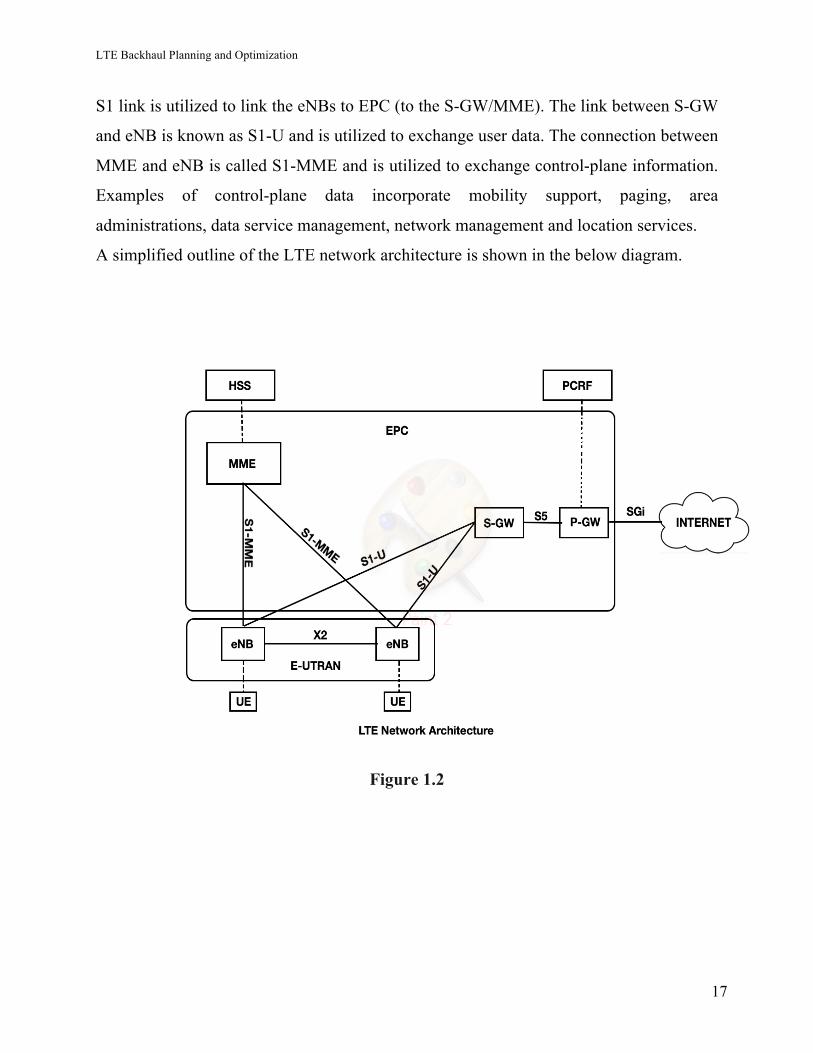
S1 link is utilized to link the eNBs to EPC (to the S-GW/MME). The link between S-GW
and eNB is known as S1-U and is utilized to exchange user data. The connection between
MME and eNB is called S1-MME and is utilized to exchange control-plane information.
Examples of control-plane data incorporate mobility support, paging, area
administrations, data service management, network management and location services.
A simplified outline of the LTE network architecture is shown in the below diagram.
Figure 1.2
LTE Backhaul Planning and Optimization
18
2.1 Below is the explanation for different elements in the architecture: -
2.1.1 User Equipment (UE): -
User Equipment (UE) is any gadget used straight forward by an end-client to
communicate in the Long-Term Evolution (LTE) and UMTS (Universal Mobile
Telecommunications System). This could be a telephone, a computer, laptop with
a mobile broadband modem, or some other equipment. It links with the eNodeB as
determined in the ETSI 125/136- series and 3GPP 25/36- series of specifications. The
connection between the UE (user equipment) and the eNodeB is known as an Uu.
Functions of UE: -
The UE is a device which initiates all the calls and it is the terminal device in a network.
Below are the tasks towards the core network handled by UE.
• Mobility management • Call control • Session management • Identity management
The relating protocols are delivered transparently via a NodeB, that is, NodeB cannot
change, use or understand the data sent by the client. These protocols are also known
as Non-Access Stratum protocols. The UE is a gadget which starts every one of the calls
and it is the terminal gadget in a system.
2.1.2 eNodeB: -
eNodeB (called as Evolved Node B too) is the component in E-UTRA of LTE which is
the advanced version of the component Node B in UTRA of UMTS. The equipment
which is linked to the cell phone network which communicates directly with mobile
handsets (UEs), as a base transceiver station (BTS) (in GSM) systems.
Generally, a Node B has least functionality, and Radio Network Controller (RNC)
controls it. there is no different controller component in any case with an eNB,. This
improves the architecture and permits lower response times.
LTE Backhaul Planning and Optimization
19
2.1.3 Serving Gateway (S-GW):
During the handover, while the User equipment’s are moving between eNodeBs ,S-GW
is the local mobility host and it manages user-plane. S-GW is the interface between the
radio part of the network and the EPC. It is the center point on which every IP packets
can be transferred through. This takes the IP based data traffic between mobile user and
the outside networks. In addition, when the UE is sit idle, it keeps all information about
the bearers and it operated as a buffer for DL data when the MME is starting paging
messaging of the UE(Client) for bearer’s reestablishment. S-GW can have different
administrative undertakings in the system.it accumulates information for charging, for
example, as the traffic load on the link whether transmitted or received by a client.
Furthermore, it functions as mobility host for internetworking with the other 3GPP
technologies for example UMTS and GPRS. On the other hand, logically, this portal is
linked to the PDN gateway.
2.1.4 Packet Data Network (PDN) Gateway (P-GW):
PDN gateway(P-GW) is the center point among the EPC and the outside IP systems and
it is mainly responsible for allocating and dividing the IP addresses for the User
Equipment, other than enforcing the QoS(Quality of service) and flow based charging.
The PDN gateway follows the duty to circulate and sort out the IP packets in the system
downstream into various QoS based standard channels and bearers as on the Traffic Flow
Templates (TFTs). P-GW is viewed as the default gateway and also it functions as packet
filtering and lawful interception which contains observing the signaling data as well as to
the system management information. It can also act as a mobility host for internetworking
with non 3GPP technologies for example: - High Rate Packet Data (HRPD) (also known
as 1xEV-DO in CDMA) and WiFi.
2.1.5 Home Subscriber Server (HSS): -
It contains the dynamic information to monitor the MME names to which client relates to
it. HSS also contains data for the client's System Architecture Evolution (SAE)
subscription, for example, any roaming access limitations and QoS profile. In addition,
this includes the Packet Data Network (PDNs) information that permits clients to link to
LTE Backhaul Planning and Optimization
20
the PDN (e.g., Internet, IMS). It additionally plays a part in authentication and security
because of its capability to integrate the Authentication Center (AuC) which find out the
security keys and vectors of authentication in the system.
2.1.6 Mobility Management Entity (MME):
It is the main control hub point that is responsible for the signaling among the core
network and the UE. This is viewed as the end point of the Non-Access Stratum (NAS)
that plays a main part in starting and maintaining the all EPS bearers. It has a key role in
registering all user equipment in a network, taking care of mobility functions between
core network and UE, and making and keeping IP connectivity.
Access Stratum (AS) protocols are running between UE and eNodeB. Thus, NAS works
between UE and a core system. Whereas, AS functions between the UE and the radio
systems.
There are two sort of main roles by the MME given as follows: -
• Bearer Management in the network • Connection Management
In the NAS protocol system, the former is operated by session management layer and is
identified with the establishing, releasing bearers and maintaining but the latter is
controlled by the link or mobility management layer and is belonged to setting up link
between the UE and network alongside providing security.
Indeed, the MME is responsibilities are the following: -
• Control of bearers • Appropriating the paging message to eNBs • Mobility control for clients in idle state • Security functions • Ensuring NAS signaling integrity and the ciphering
LTE Backhaul Planning and Optimization
21
2.1.7 Policy Control and Charging Rules Function (PCRF): -
It’s one role is that these are flow- based and residing in the P-GW. The QoS approval,
which is including of the QoS Class Identifiers (QCI) and the bit data rates, characterizes
the PCEF hadling for specific data flows in harmony and the agreement with the client's
subscription profile.
2.2 The Issues Surrounding LTE
This is one of the issue that which Voice communication is the developing related to the
use of the LTE standard. All GSM, CDMA2000 and UMTS are circuit switched
networks, yet the ITU-R standard network for a 4G system calls for packet switching
exclusively through an IP network, something LTE supports. This concludes that carriers
those are switching to LTE should adjust their voice call system to support the new
switching. As of now, most suppliers use circuit exchanged fallback (CSFB), while LTE
support just voice calls "fallback" and data mobile services to being circuit services. This
one is an easy to setup and work, however means setup time for a more longer call. The
no doubt possibility for future packet switched network voice calls rotates around the
utilizing of VoLTE (Voice Over LTE), which use the IP Multimedia Subsystem system.
LTE offers various advantages over current 4th generation and built the backbone of
numerous current 4G networks. Sprint has constructed its own LTE + network. This
finally catching the data speed up to 4G speeds essential for true LTE networks with
these new architectures of networks.
References: -
[1]https://www.scribd.com/document/294256499/C04-Wireless-Telecommunication-
Systems-pdf
[2] http://www.sciencedirect.com/science/article/pii/B9780124051621000034
[3] https://www.scribd.com/document/267431731/LTE-architechture
[4] https://www.scribd.com/document/227355795/Lte-vs-Wimax
LTE Backhaul Planning and Optimization
22
[5] https://en.wikipedia.org/wiki/User_equipment
[6] http://go.radisys.com/rs/radisys/images/paper-lte-eutran.pdf
[7] https://en.wikipedia.org/wiki/3GPP
[8]http://docplayer.net/18409042-Lte-traffic-generation-and-evolved-packet-core-epc-
network-planning-dima-dababneh-b-sc.html
[9] https://www.slideshare.net/ramizzz/essentials-of-lte-and-lte-a
[10] http://documents.mx/documents/lte-architechture.html
LTE Backhaul Planning and Optimization
23
3. Various LTE backhaul network: - 3.1 Wireline technologies: -
3.1.1 Local Ethernet: -
Local Ethernet (electrical or optical Ethernet) least rate utilization should be 100 Mbps,
yet 1 Gbps is prescribed. The distance which can be spanned by local Ethernet is
restricted. In most of the time, Ethernet might be the local medium to connect to other
components on a similar site.
3.1.2 DSL (digital subscriber line): -
The existing copper infrastructure can be reuse in Digital subscriber line (DSL). Various
standards support different bandwidth. The achievable performance and capacity
emphatically rely upon the cable lengths of the final copper connection. Mostly probably
in a consolidated leased line, DSL is to be used for mobile back- haul, which begins with
a CPE (customer premises equipment) situated at the eNB and closures at a handover
point in the aggregation network. Necessary steps for the further planning are the
following abilities of the DSL line:
• Monthly cost
• Bandwidth in UL and DL
• Availability
• Delay/delay variation
• Asymmetry of delay.
On the other side, some DSL technology causes extra challenges for some PTP
implementations. Most "any sort of" digital subscriber lines (xDSL) don't serve the bit
rates required by LTE extensive bandwidth deployments, an eminent exception being
low-bandwidth deployments at 10 MHz FDD bandwidth or less. Reliability of xDSL may
also be a concern toward the operator henceforth making it a specialty technique utilized
for otherwise hard-to-reach areas.
LTE Backhaul Planning and Optimization
24
3.1.3 Fiber: -
A fiber connectivity to the eNB is the most favorable solution as it resolves all capacity
and performance issues of current backhaul architectures. Nevertheless, the rate of base
stations which are connected by means of fiber is still underneath 35% (2013).
Two types of fiber deployments must be differentiated: active and passive. In the active
zone two sorts of fiber scenarios are applicable:
• Grey: - which implies utilization of the fiber with a single frequency.
• Colored: - which implies utilization of the fiber with multi frequencies in
coarse wavelength division multiplexing (CWDM) and dense wavelength
division multiplexing (DWDM) systems.
The wavelength division multiplexing (WDM) network are important to utilize fiber
deployments for more efficiently. A single fiber cable can be utilized with several
frequencies (color) simultaneously. They are generally utilized in backbone networks,
additionally first deployments in the aggregation part of backhaul systems come up. The
single mode use of fiber is generally utilized for gigabit Ethernet (GbE) connections.
From a planning viewpoint, the fiber capacity connection is steady and does not rely
upon any environmental limitation. For availability perspective, it is important to monitor
the conduct usage to avoid the utilization of excess fibers in a same conduct.
On the other side, there are PON (passive optical networks). The distinction to "active"
optical systems is that the connection utilizes passive components, for example, optical
splitters to divide the signal in point-to-multipoint connectivity, the advantage here being
a potential cost saving. The capacity between leaf hubs is shared by TDM. The distance
between the root hub and the leaf hubs can be up to 20 km. The capacity given might be
symmetrical or asymmetrical, with leaf hub bit rates up to 2.5 Gbps (gigabit-capable
passive optical system [GPON]) or even 10 Gbps for 10 gigabits/passive optical system
[XG-PON]) in downstream and 1.25 Gbps (2.5 Gbps for XG-PON) in upstream.
LTE Backhaul Planning and Optimization
25
3.1.4 DOCSIS (data over cable service interface specification): -
The data over cable service interface specification (DOCSIS) enables digital data
transport utilizing cable-TV network connectivity. With a 6 MHz RF channel a Downlink
bandwidth of 38 Mbps can be accomplished. Contrasted with DSL, a higher Uplink
performance of up to 27 Mbps can be accomplished. Even though a further bundling of
channels is possible, to accomplish higher bandwidths the technology is not frequently
used for the backhaul of macro sites. In any case, with the arrival of DOCSIS 3.1, it will
be possible to offer even 10 Gbps Downlink and 1 Gbps Uplink capacity in specific
conditions.
3.2 WIRELESS: -
3.2.1 POINT TO POINT microwave radio: -
Even though the bandwidth demand of eNBs grown significantly, MWRs are still a
suitable answer for many base stations. This is because of new technologies like higher
modulation schemes, double polarization and MIMO technologies.
Advanced hardware totally includes all the committed functionality of the microwave
into the ODU (outdoor unit) and is connected to any sort of indoor part via the Ethernet
(providing power sometimes). Any type of L2/L3 functionality is served by the indoor
unit, which may be a switch or router.
Significant viewpoints for the planning and optimization are link capacity and link
availability. Because of adaptive modulation systems the availability may not be on/off,
but rather relying upon the climate conditions the link capacity might change. In addition,
molding and as well as QoS mechanisms of the equipment must be considered.
All the technologies said before can likewise be offered as leased line. Moreover, mixed
solution can be figured it out. For example, the first mile between eNB and a first access
point of a rented line supplier is owned by the mobile operator followed leased line,
which is ended at an IP core site of the mobile operator. The different offers of leased
lines are very unpredictable. A wide range of SLAs and different QoS usage are offered.
What's more, a wide range of leased line suppliers exist with different capabilities and
LTE Backhaul Planning and Optimization
26
they may differ from city to city. Most of the time, the first mile rules the cost of a leased
line, as the availability of the required medium is the same for the mobile operator or a
leased line supplier.
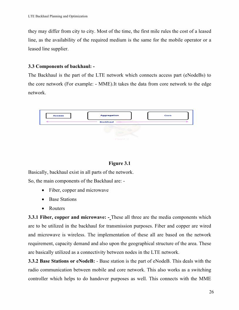
3.3 Components of backhaul: -
The Backhaul is the part of the LTE network which connects access part (eNodeBs) to
the core network (For example: - MME).It takes the data from core network to the edge
network.
Figure 3.1
Basically, backhaul exist in all parts of the network.
So, the main components of the Backhaul are: -
• Fiber, copper and microwave
• Base Stations
• Routers
3.3.1 Fiber, copper and microwave: - These all three are the media components which
are to be utilized in the backhaul for transmission purposes. Fiber and copper are wired
and microwave is wireless. The implementation of these all are based on the network
requirement, capacity demand and also upon the geographical structure of the area. These
are basically utilized as a connectivity between nodes in the LTE network.
3.3.2 Base Stations or eNodeB: - Base station is the part of eNodeB. This deals with the
radio communication between mobile and core network. This also works as a switching
controller which helps to do handover purposes as well. This connects with the MME
LTE Backhaul Planning and Optimization
27
(Mobile management entity) with S1 interface and connected with other eNodeB with X1
interface.
3.3.3 Routers: - Routers are used in between the eNodeBs and core networks. These are
to be used for the carrier aggregation or dividing the data speed into the eNodeBs.
3.4 Understand and discuss pros and cons of various backhaul networks: -
3.4.1 LOCAL ETHERNET: -
Advantages: -
• We can use the technology without a delay. Not having to go through that
processing and translation of the Ethernet packet at either end (to encapsulate it
into a variation of HDLC link protocol) could speed things along.
• This is affordable and very easily available.
• It provides the guaranteed bandwidth (WiFi is sharable, broadcast medium.
Ethernet can also be dedicated if needed.)
• Managed Switches can manage the physical security (but security layers have
some limitations.)
• Power over Ethernet: By using the Ethernet cabling to provide power for small
routers/switches/devices so that power wiring is not necessary to be delivered
for the every endpoint.
Disadvantages: -
• There is always Limited physical access It means Ethernet ports in a chamber
must be in particular locations.
• Physical connections can fail, especially if we use it frequently connecting n
disconnecting.
• Sometime bandwidth needs to upgrade for the cable replacement.
LTE Backhaul Planning and Optimization
28
3.4.2 DSL (digital subscriber line): -
Advantages: -
• DSL is good for bursty type of traffic patterns.
• Cheap line charges from the telephone organization.
• It has high bandwidth.
• With DSL, your telephone line will dependably work independently from your
Internet line which implies you can utilize either or both and harm to one won't
really mean harm to the next.
• Integration: DSL will effectively interface with ATM, Nx64, and WAN
innovation. Working from home may get significantly simpler.
• Security: Unlike link modems, every endorser can be arranged with the goal
that it won't be on a similar system. In some link modem systems, different
PCs on the link modem system are left noticeably defenseless and are
effectively vulnerable to break ins and additionally information pulverization.
• Independent administrations: Loss of rapid information does not mean you lose
your telephone utility. Envision your phone, TV, and Internet get to going out
when a link organization enhancer/repeater bites the dust.
Disadvantages: -
• It has limited accessibility
• Distance reliance: The more distant you live from the DSLAM (DSL
Access Multiplexer), the lower the information rate. The longest run lengths
are 18,000 feet, or somewhat more than 3 miles.
• Low or no CIR (Committed Information Rate). This implies as activity over
the telco switch builds your information could as a result, be bolted out,
until call volumes and other movement dies down.
• No current standardization: A man moving starting with one territory then
onto the next might find that their DSL modem is simply one more
LTE Backhaul Planning and Optimization
29
paperweight. Clients may need to purchase new hardware to just change
ISPs. Expect institutionalization inside 1-2 years. As of now in U.S. West
domain the rendition of DSL being executed is RADSL or Rate Adaptive
DSL.
• Downtime after line disappointment could be weeks contrasted and days for
ISDN and hours for information circuits, for example, Frame Relay and
Point to Point circuits
• Reliability and potential down time issues settles on DSL an exceptionally
hazardous decision for mission basic frameworks unless backup / fail over
links are put in place.
3.4.3 FIBER
Advantages: -
• Security - Optical strands are hard to tap. As they don't emanate
electromagnetic energy, discharges cannot be intercepted. As physically
tapping the fiber takes incredible aptitude to do undetected, it is the secure
accessible media for conveying the classified information.
• Safety - Since the fiber is known as a dielectric, it doesn't present a spark
risk.
• Weight - Fiber optic links are substantially more slender and lighter than
metal wires. They likewise possess less space with links of a similar data
limit.
• Cost - The crude materials for glass are abundant unlike copper. This
implies glass can be made more inexpensively than copper.
• Flexibility - An optical fiber has more noteworthy elasticity than steel or
copper strands of a same width. It is adaptable, twists effectively and resists
most corrosive substance that attack copper cable.
• Size - In contrast with copper, a fiber optic link has almost 4.5
circumstances as much limit as the wire link has and a cross sectional area
LTE Backhaul Planning and Optimization
30
• Interference - Fiber optic links are insusceptible to electromagnetic
obstruction. It can likewise be keep running in electrically uproarious
conditions without worry as electrical clamor will not affect fiber.
• Bandwidth - Fiber optic links have a substantially more prominent data
transfer capacity than metal links. With the upmost, single mode link
utilized by mobile phone ventures for long separated medium transmission,
the transfer speed outperforms the necessities of today's applications and
gives space for development tomorrow.
Disadvantages: -
• Protection - Optical strands require more security around the link contrasted
with copper.
• Transmission – The transmission on an optical fiber needs repeating at
interims.
• Cost - Cables are costly to introduce however last longer than copper links.
• Fragile - Fibers have transmission loses or could be broken when wrapped
around bends of just a couple of centimeters' range. In any case, by
encasing strands in a plastic sheath, it is hard to twist the link into a
sufficiently little range to break the fiber.
3.4.4 DOCSIS (data over cable service interface specification)
Advantages: -
• Excellent client benefit: This is yet another preferred standpoint of a cable
connection. Link organizations generally give next to no down time and
astounding client administration to its clients. If you find any problem with
your cable internet connection, you can get a solution on just a phone call.
Several customer service operators working with internet customers are so
intelligent to know their business very well. Also, since the link coming
into your house is for the most part shrouded underground, there are less
LTE Backhaul Planning and Optimization
31
things that can go off bar. In this way, benefit disturbances are extremely
rare.
• Consistency: Reliability has for quite some time been issue of different
types of broadband due to aging infrastructure and separation issues. Digital
web gives more solid association less lost bundles for the most part as
indicated by both autonomous and industry considers.
• No limitation of area: In addition to purpose of digital web, you are not
entirely constrained to a particular area as you are with other web
administrations. You can be at a considerable separation from the link
organization's administration focus and still can get practically flawless
administration.
• Faster Connection speed: Many clients consent to the way that the best
favorable position of digital web is that it offers the speediest and most
inconvenience free association accessible. They settle for this because of
the fact that a web link utilizing a cable modem usually ensures a more
elevated amount of transfer bandwidth than other broadband, and more data
transmission implies speedier speed.
• High speed: The rates gave by the link broadband web are substantially
speedier when contrasted with different sorts of broadband web. This
implies digital web is a magnificent substitute to other broadband as far as
speed. If there are only a few of clients associated with your cable modem,
you may even get quicker web speeds than DSL.
• Works without a telephone line: It does not dependent of telephone line to
operate. This is valuable because the client does not need to dial to interface
with the web and subsequently pay no dial-up charge. Since digital web
does not require its clients to have a phone line to work, access to both web
and telephone administration is conceivable. There is no limitation on
utilizing the web. You can interface with the web notwithstanding when the
phone line is being used.
LTE Backhaul Planning and Optimization
32
Disadvantages: -
• Slow speed amid pinnacle hours: The information exchange speed gets
moderate during peak hours. This is the reason behind why web association
slows down in the morning and night.
3.4.5 POINT TO POINT microwave radio
Advantages: -
• Radio frequency spectrum is getting crowded day by da. Microwave
technology helps to manage crowded spectrum with the utilization of high
particular recipients, manage (PSK, QAM, SSB and so on.) and spread
range methods, information compression.
• The microwave range has bigger data transfer capacity and large amount of
data can be transmitted using it.
• Microwave range is separated into various channels according to
application. The middle frequencies for these channels are allotted with
gaps between them so channels will not overlap and don't make interference
to adjacent channels.
• Microwave communication is utilized since before days as one of the Line
of Sight Communication in sloping remote territories where different
method for wired communication is impractical to be installed. Microwave
and satellite communications are regent decision in such places.
Disadvantages: -
• For the frequencies, which are beneath 30MHz standard circuit
investigation can be connected. For the frequencies in the microwave go, E-
H wave investigation should be connected.
• As microwave communication is constrained to line of sight mode as it
were, other methods of correspondence are unrealistic.
• As we know lumped segments, for example, resistors, inductors and
capacitors don't have same attributes at microwave frequencies as they have
LTE Backhaul Planning and Optimization
33
at lower frequencies. Henceforth, it is hard to execute these segments at
microwave frequencies.
References: -
[1] https://en.wikipedia.org/wiki/Digital_subscriber_line
[2] BOOK--LTE Backhaul planning and optimization by Esa Markus Metsälä and Juha
T.T. Salmelin ,Nokia Networks, Espoo, Finland
[3] https://en.wikipedia.org/wiki/Digital_subscriber_line
[4] https://en.wikipedia.org/wiki/Wavelength-division_multiplexing#Dense_WDM
[5] http://slideplayer.com/slide/5992022/
[6] https://www.quora.com/What-are-the-advantages-and-disadvantages-of-ethernet-
cable
[7]http://www.fujitsu.com/global/documents/about/resources/publications/fstj/archives/v
ol48-1/paper11.pdf
[8] https://en.wikipedia.org/wiki/Microwave_transmission
[9] http://www.ittoday.info/AIMS/DCM/51-20-96.pdf
[10] https://www.quora.com/What-are-the-advantages-and-disadvantages-of-ethernet-
cable
[11] http://www.state.net/dsl/DSLadvantages.html
[12] http://services.eng.uts.edu.au/~akadi/ite/major_assignments/barber/advdisad.htm
[13] http://www.rfwireless-world.com/Terminology/Advantages-and-Disadvantages-of-
Microwave-Communication.html
[14] http://brilliantclarity.com/cable-internet-access-advantages-and-disadvantages/
[15] https://www.scribd.com/document/270126213/RF
[16] http://lteexpert.blogspot.ca/2014_09_01_archive.html
[17] https://en.wikipedia.org/wiki/EnodeB
[18] LTE Traffic Generation and Evolved Packet Core (EPC) Network Planning by Dima
Dababneh, B.Sc
[19] https://www.slideshare.net/cleopettra/optical-fiber-43549606
LTE Backhaul Planning and Optimization
34
4. LTE BACKHAUL PLANINNG: -
To achieve best LTE Backhaul planning, First of all we need to see the Requirement and
objective which we need to fulfilled.
4.1 Requirements for LTE: -
The needs and aim set forth for this system are very rigid because LTE Network is
believed to be competitive for the many coming years, therefore the main aim of the
advancement is to further improve services provisioning and to make this economically
cheap for user/operator. This can be made to happen by using again of the current mobile
network spectrum, interoperability among current and future system reuse of already
existing nodes and production of economically devices. This requires smooth and
flawless transition from current telecommunication system.
More particularly, some essential needs and capability aims for the LTE Network are: -
4.1.2 The primary requirements include below points: -
• Simplicity: Simplified operations are needed to permit efficient network deployment,
diminish the total cost of ownership (TCO) and maintenance and administration.
End- to-end visibility and control of components at every mobile site (macro and small)
is essential for smooth-running OAM, with surgical remote find the problem. A guideline
approach to site backhaul provisioning and intrigue is needed, nevertheless of location or
access type. It is pivotal that the system should actively indicate when the key
performance indications (KPIs) are not in bounds and service level agreements (SLAs)
have not been met.
• Scalability: The backhaul mobile network should be scalable smoothly to bear
increasing cell site’s count at higher capacities. Depending on the requirements, need to
use different bandwidths (From 1.25 to 20 MHz).
Network resiliency is critical to supporting the client’s QoE. The failure by scalable
recovery procedure become more crucial to limit of the breadth of influence should
system resources sometimes become unavailable as cell site’s number increases home in
LTE Backhaul Planning and Optimization
35
on bigger capacity head-end systems. LTE and LTE-Advanced are transiting to an whole
IP network, any-to-any backhaul network, MPLS for explicit traffic engineering and IP-
optimized transport over a huge scalable Ethernet architecture.
• Flexibility: The description of a mix of macro and small cells in an LTE or
LTE-Advanced environment also brings the need to dominance the nearest, most
economical mobile backhaul access architecture that can complete the quality of service
(QoS) needs. Mobile communication operators must have the capacity to give proper
access to network assets, for example, link BW, for a scope of traffic streams, particularly
when systems are worked at high use levels. This outcome can be seen in a greater
diversity in mobile backhaul access types, increasing a requirement for more perfect
troubleshoots that can work consistently whether it is microwave, xDSL, Ethernet or
Fiber and GPON. In addition to LTE and LTE-Advanced, support for 2G, 3G and Wi-Fi
network services are needed. Operations, administration and management (OAM),
spilling video, telemetry and voice over Internet Protocol (VoIP) can be incorporated
traffic streams. Specifically, LTE and LTE-A likewise request precise stage
synchronization to bolster video communicate, interface administration and time division
duplexing.
• Availability: The end-user service gives the availability requirements of the backhaul
network. An average necessity could be an availability estimation of 99.95%. Mostly, the
last access hop overwhelms the accessibility.
• Capacity: LTE base stations can give an enormous development of conceivable
bandwidth as compared to 2G and 3G. Only under ideal air interface conditions peak
rates must be accomplished. For the control, administration and synchronization traffic,
extra capacity is required. This traffic is very small as contrasted with the user traffic.
To expanding capacity, coverage and to delivery of a perfect QoE for end users as LTE
and LTE-Advanced are implemented, the backhaul network should be flexible enough.
LTE Backhaul Planning and Optimization
36
4.1.3 Some more below requirements are given below: -
• Low latency: Latency target requires to set as 5ms for both User and Control Plane.
• Enhance Cell edge performance
• Peak Data Rates: 120 Mbps for Downlink, 50 Mbps for Uplink.
• Network must be able to optimize for less mobile data speed but also support to the high
mobile data speeds
• Complexity in the network should be negligible in both system and end points.
• Migration from existing networks to new networks should be easy.
• Support only for the Packet Switched Domain.
• The interface’s count should be minimization and Simplification.
References: -
[1] http://lib.tkk.fi/Dipl/2009/urn100056.pdf
[2] BACKHAUL CONSIDERATIONS FOR LTE AND LTE-ADVANCED by
ALCATEL-LUCENT [3] http://www.ericsson.com/res/docs/2014/ericsson-mobility-report-june-2014.pdf
[4] http://docplayer.net/11419404-Dimensioning-of-lte-network-description-of-models-
and-tool-coverage-and-capacity-estimation-of-3gpp-long-term-evolution-radio-
interface.html
[5] http://docplayer.net/18757430-Ip-mpls-mobile-backhaul-for-heterogeneous-networks-
enhance-quality-of-experience-and-streamline-operations-with-alcatel-lucent-ip-mpls-
macro-and.html
LTE Backhaul Planning and Optimization
37
5. Network Topology and Transport Media: -
In this segment on system topology and transport media the goal is not to focus on the
transport media selection in detail however to explain its impact on the network
topologies.
5.1 Access Network Topologies and Media:
In the mobile backhaul network, wireless transport media is frequently used, when the
supported capacity by the microwave hardware are sufficient for the expected and
determined traffic, and fiber is not accessible cost-efficiently.
Tree, chain, star or ring, or a blend of these are typically used topologies. Chosen
topology affects the feasible resiliency techniques; Protection strategies for a ring
topology are not quite the same as those for a chain topology. Below diagram presents
these conventional system topologies for the Mobile system.
High-level configuration answers the below inquiries related to topology planning:
• What number of eNBs can be associated with a hub in a star topology?
• What number of eNBs can be associated with a chain?
• What number of eNBs can be associated with a ring?
To find the answer for above inquiries, examination of accessible capacities limits is
required, as well as hub site’s capacity, hub site connection to the aggregation network
and the planned resiliency techniques. At the point when link capacities are known and
the redundancy technique chosen, the maximum hop’s count that the capacity permits can
be defined. The higher the capacity per eNB, the less hops can be implemented or less
eNBs can be incorporated into the ring.

LTE Backhaul Planning and Optimization
38
Figure 5.1. TOPOLOGY DIAGRAM
For wireless network access, when both delay and transmission capacity is considered, it
does not bode well to chain more than a few eNBs. The star design is additionally the
easiest to work and maintain. Any failure in the main mile connection will bring about
transmission failure, yet that is easy to find and connection failure has an impact to one
site only. Some of the connections can be just partially filled that can bring about higher
transmission costs.
Ring topology gives assurance against single connection failure in the ring, and gives
path diversity and consequently enhances the resiliency compared to star, chain or tree
topologies, without the need to deployed a double connection capacity with respect to
link protection.
LTE Backhaul Planning and Optimization
39
Fiber is accessible in urban regions, yet availability is significantly dependent of the
nation in question. If fiber is accessible, there is no reason to utilize other media to link
the eNB to the aggregation point.
To link eNBs to aggregation sites, leased lines can be utilized when they are available,
and this is a realistic access method. If the delivery time for rented line is good and cost is
reasonable as compared to quality, then rented lines can be a quick approach to deploy
remove the backhaul.
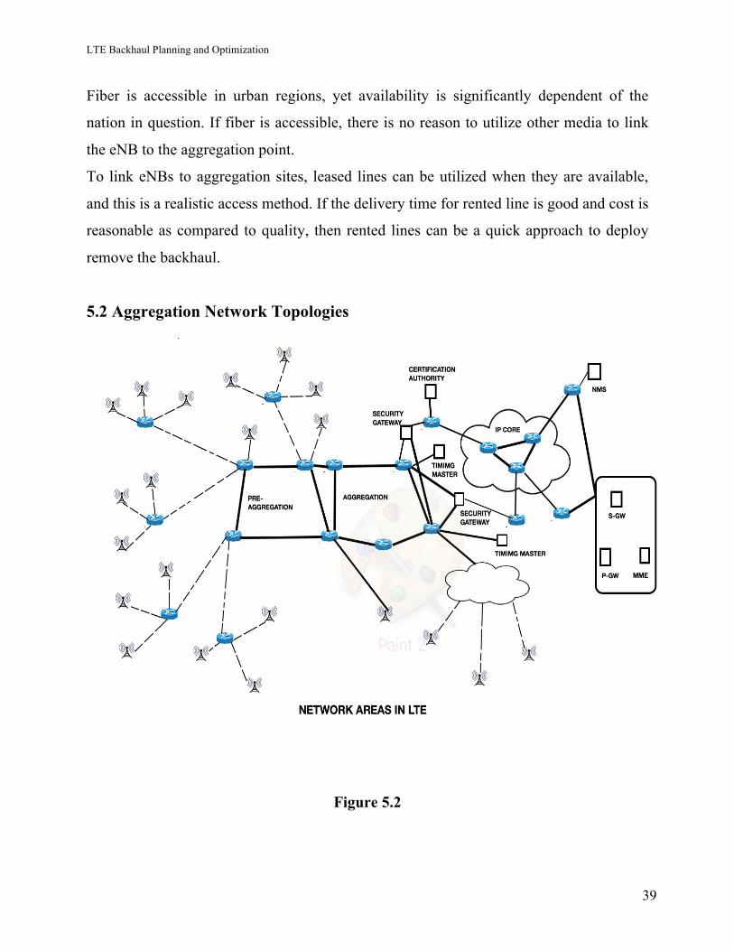
5.2 Aggregation Network Topologies
Figure 5.2
LTE Backhaul Planning and Optimization
40
Aggregation network implies further concentrating the eNB traffic toward the core
system sites. S1-flex links the eNB to numerous core sites with MME, S-GWs and
regularly security gateways (SEGs), empowering load sharing and geo-redundancy for
the core system components. Accordingly, the aggregation network configuration must
support connectivity from eNB to multiple core system sites. The topology is generally
ring structure, enabling redundancy and offering versatile connectivity to the core system.
An example of this topology is given above in the diagram.
An aggregation network gives links to the eNBs, and an availability requirement for the
aggregation system is higher than the total aggregate availability of the first mile. This
can be accomplished by utilizing protection techniques like Ethernet ring protection
(ERP) and routing gateway redundancy, explained further in the following segment.
The capacity required for the QoS for mobile traffic and the aggregation network, should
be sufficiently flexible to oblige the development and upgrade of the system.
The core sites with MME and S-GW are linked together utilizing a high-capacity core
backbone network.
References: -
[1] https://www.scribd.com/doc/152880920/LTE-Transport-Tutorial
[2]http://www.3gpp.org/technologies/keywords-acronyms/101-carrier-aggregation-
explained
[3] BOOK--LTE Backhaul planning and optimization by Esa Markus Metsälä and Juha
T.T. Salmelin ,Nokia Networks, Espoo, Finland
[4] LTE backhauling deployment scenarios by NGMN Alliance
LTE Backhaul Planning and Optimization
41
6. Backhaul Network Deployment Scenarios
Operators can deploy the backhaul network from various perspectives. Considering the
meaning of network area, the backhaul connectivity from the eNB to the core system
comprises of access, pre-aggregation and accumulation areas. These can have distinctive
topologies and media, redundancy and security components and logical system structures.
There are numerous choices, and below section should be considered as an introduction
to backhaul network deployment scenarios utilizing different technologies, exhibiting
some of the examples here.
6.1 Implications to Backhaul Scenarios
Simply because the way of local Ethernet bridging, for connectivity it is prescribed to
depend on IP layer forwarding for site-to-site connectivity as opposed to bridging. The
Ethernet still frequently serves as the underlying layer, as a point-to-point connection, and
as a physical port. The inclination of IP to limit and isolate issues generally reduces the
effect of failures on the system operation. Likewise, troubleshooting is less complex.
Security is an essential consideration in the LTE backhaul. If the layer underneath IP is
not completely secured, the backhaul network is compromised to an extent. In any case,
when IPsec is utilized to secure the traffic, the IPsec cryptographic protection itself
remains and the dangers that exist are restricted. Still, for security reasons, it is suggested
that instead of depending on Ethernet bridging for linking the IP layer should be utilized
at whatever feasible, with IP layer access controls and cryptographic safety of the IP
layer with IPsec.
6.1.1 Ethernet Services
• Metro Ethernet Forum (MEF) has characterized abstract services (e.g.
E- Line for point- to- point and E- LAN for multipoint). The advantage of the
service is that clients (e.g. mobile operators) can now utilize it between sites
over a physical separation more than that of a single site or LAN.
LTE Backhaul Planning and Optimization
42
• MEF is skeptic to the technology being implemented the service, and just
characterizes the attributes the user of the service sees. So, that the service can
be executed by any technology which will be fit for sending Ethernet frames
and connectivity and different characteristics as explained in the service. Both
port- based (non- VLAN- aware) and VLAN- based services are being
carried.
• MPLS is normally utilized by service providers to send different kind of L2
and L3 services. At the point when MPLS is used, Ethernet connectivity is
emulated, and the service supplier can offer the Ethernet facility by MPLS
rather than local Ethernet bridging.
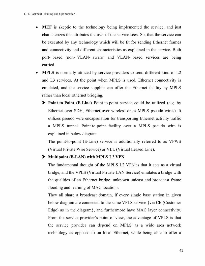
Ø Point-to-Point (E-Line) Point-to-point service could be utilized (e.g. by
Ethernet over SDH, Ethernet over wireless or as MPLS pseudo wires). It
utilizes pseudo wire encapsulation for transporting Ethernet activity traffic
a MPLS tunnel. Point-to-point facility over a MPLS pseudo wire is
explained in below diagram
The point-to-point (E-Line) service is additionally referred to as VPWS
(Virtual Private Wire Service) or VLL (Virtual Leased Line).
Ø Multipoint (E-LAN) with MPLS L2 VPN
The fundamental thought of the MPLS L2 VPN is that it acts as a virtual
bridge, and the VPLS (Virtual Private LAN Service) emulates a bridge with
the qualities of an Ethernet bridge, unknown unicast and broadcast frame
flooding and learning of MAC locations.
They all share a broadcast domain, if every single base station in given
below diagram are connected to the same VPLS service {via CE (Customer
Edge) as in the diagram}, and furthermore have MAC layer connectivity.
From the service provider’s point of view, the advantage of VPLS is that
the service provider can depend on MPLS as a wide area network
technology as opposed to on local Ethernet, while being able to offer a
LTE Backhaul Planning and Optimization
43
multipoint Ethernet LAN facility to the user. Hence also drawbacks that
exist in utilizing Ethernet bridging for connectivity are significant for the
use of MPLS L2 VPN when looking from the perspective of the user.
Figure 6.3
LTE Backhaul Planning and Optimization
44
6.1.2 Comparison
E-Line suits the requirements of the eNB backhaul superior to anything E-LAN
does, in the sense that just a point-to-point service is required and there is no direct
Ethernet layer network required between multiple sites.
6.2 L3 VPN Service
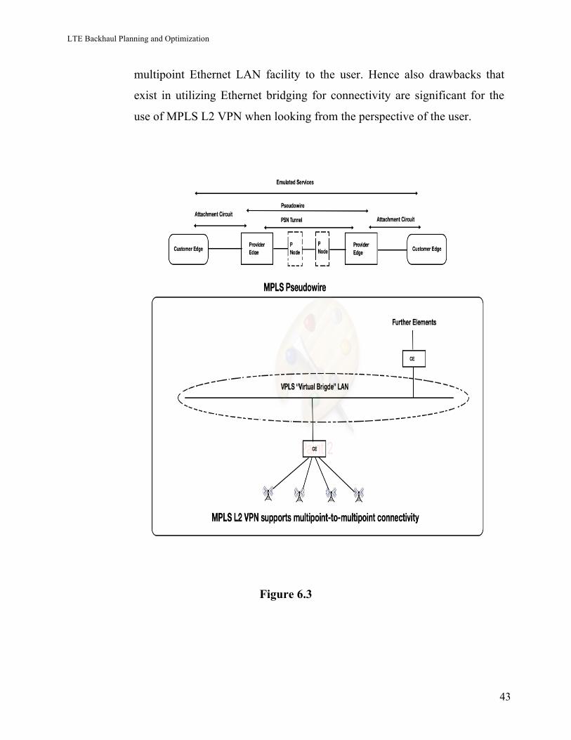
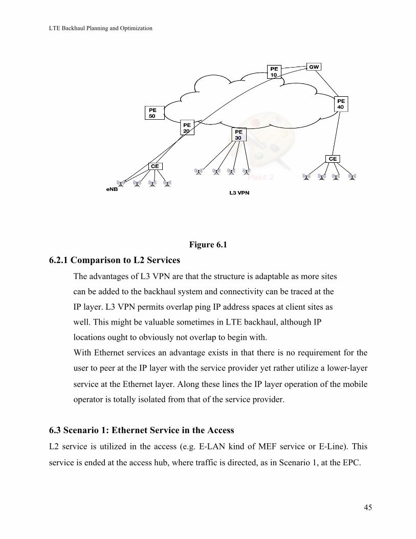
• MPLS L3 VPN
MPLS is additionally used to deploy L3 VPN (IP) services. Here, each eNB peers
directly with the MPLS Provider Edge (PE) node, or via Customer Edge (CE).
MPLS L3 VPN is a "cloud" providing IP network between all the client sites, as
characterized by the service. Every client's routing data is kept separate by the
utilization of virtual routing and forwarding (VRF) instances, and traffic can be
mapped to the VRFs based on, for example: - IP addresses and/or VLANs. A
logical architecture is given below in the diagram.
In the LTE backhaul, VRFs can be designed to have U- , C- and M- plane traffic
as particular customers of the L3 VPN service having either dedicated VRF per
traffic kind or sharing, for instance, a VRF with client and control plane traffic.
VRF partition has direct implications for VLAN and routing planning in the eNB.
Consuming a different VRF for U-plane helps in investigating as the routing
information and connectivity related to the U-plane can be independently tracked.
So also, management traffic is frequently needed to be kept separate from both the
client and the control plane to expand security against threatening assaults
utilizing the management connectivity.
VRFs could also be divided into IPsec and non-IPsec traffic.
LTE Backhaul Planning and Optimization
45
Figure 6.1
6.2.1 Comparison to L2 Services
The advantages of L3 VPN are that the structure is adaptable as more sites
can be added to the backhaul system and connectivity can be traced at the
IP layer. L3 VPN permits overlap ping IP address spaces at client sites as
well. This might be valuable sometimes in LTE backhaul, although IP
locations ought to obviously not overlap to begin with.
With Ethernet services an advantage exists in that there is no requirement for the
user to peer at the IP layer with the service provider yet rather utilize a lower-layer
service at the Ethernet layer. Along these lines the IP layer operation of the mobile
operator is totally isolated from that of the service provider.
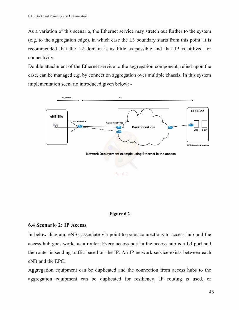
6.3 Scenario 1: Ethernet Service in the Access
L2 service is utilized in the access (e.g. E-LAN kind of MEF service or E-Line). This
service is ended at the access hub, where traffic is directed, as in Scenario 1, at the EPC.
LTE Backhaul Planning and Optimization
46
As a variation of this scenario, the Ethernet service may stretch out further to the system
(e.g. to the aggregation edge), in which case the L3 boundary starts from this point. It is
recommended that the L2 domain is as little as possible and that IP is utilized for
connectivity.
Double attachment of the Ethernet service to the aggregation component, relied upon the
case, can be managed e.g. by connection aggregation over multiple chassis. In this system
implementation scenario introduced given below: -
Figure 6.2
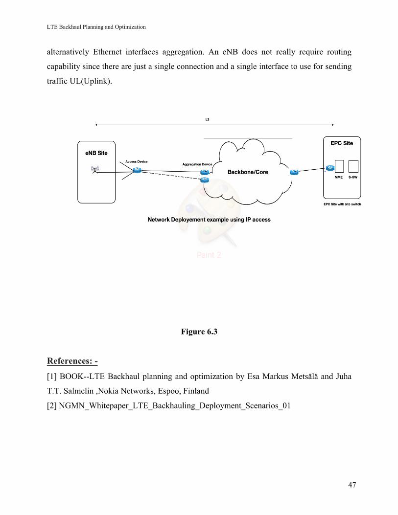
6.4 Scenario 2: IP Access
In below diagram, eNBs associate via point-to-point connections to access hub and the
access hub goes works as a router. Every access port in the access hub is a L3 port and
the router is sending traffic based on the IP. An IP network service exists between each
eNB and the EPC.
Aggregation equipment can be duplicated and the connection from access hubs to the
aggregation equipment can be duplicated for resiliency. IP routing is used, or
LTE Backhaul Planning and Optimization
47
alternatively Ethernet interfaces aggregation. An eNB does not really require routing
capability since there are just a single connection and a single interface to use for sending
traffic UL(Uplink).
Figure 6.3
References: -
[1] BOOK--LTE Backhaul planning and optimization by Esa Markus Metsälä and Juha
T.T. Salmelin ,Nokia Networks, Espoo, Finland
[2] NGMN_Whitepaper_LTE_Backhauling_Deployment_Scenarios_01
LTE Backhaul Planning and Optimization
48
7. Indoor Coverage Solutions 7.1 Different types of cells used in the LTE network: -
The Indoor services for telecommunication do not have to deal with UE (User
Equipment) that is rapidly moving. The joined factors of lower processing power and
lower PA power make the expenditure of a femto eNodeB (HeNB) much lower,
additionally make the femtocells more appropriate for high-limit indoor applications
Inside the little foot printing of femtocell, the quantity of simultaneous links does not
require to be as big as in an outdoor circumstance.
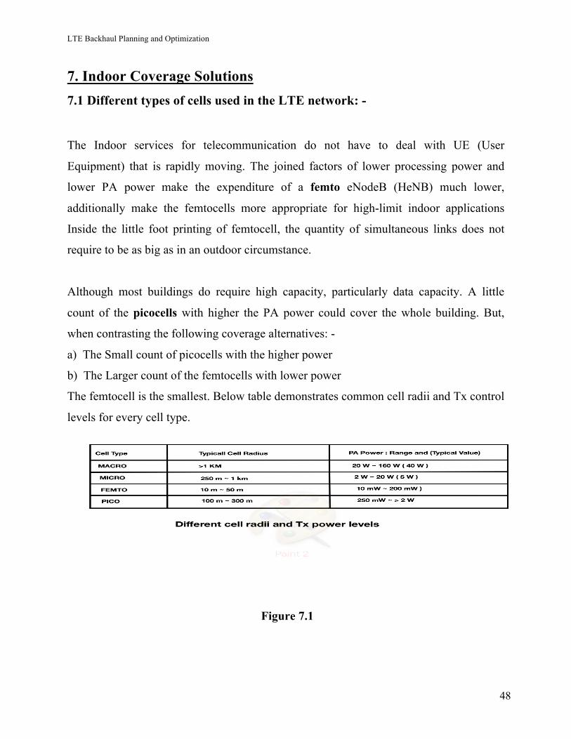
Although most buildings do require high capacity, particularly data capacity. A little
count of the picocells with higher the PA power could cover the whole building. But,
when contrasting the following coverage alternatives: -
a) The Small count of picocells with the higher power
b) The Larger count of the femtocells with lower power
The femtocell is the smallest. Below table demonstrates common cell radii and Tx control
levels for every cell type.
Figure 7.1
LTE Backhaul Planning and Optimization
49
7.1.1 Macro Cells: - These are LTE eNodeBs, which typically controls three cells.
7.2 What precisely is a small cell? On the most fundamental level, small cells are low-
powered radio access hubs, with a scope of a few meters to a mile in distance across.
There are three sorts of small cells, and running from smallest to biggest they are called
femtocells, picocells, and microcells. As a class, they are considered as " small "
contrasted with a mobile macrocell, which can have a scope of around 20 miles. The
various types of small cells have various applications.
7.2.1 Picocells offer greater capacities and coverage regions, supporting up to 100
customers over a scope of under 250 yards. Picocells are much of the time deployed
indoors to enhance poor wireless and cell coverage inside a building, for example, an
office floor or retail space.
7.2.2 Microcells are hard to exactly distinguish from picocells, yet their coverage area is
the prime delineator. Microcells can cover zones not as much as a mile in diameter and
utilizations control to limit this range. Microcells can be implemented temporarily in
anticipation of high- traffic inside a limited area, for example, a sports event, but at the
same time are installed as a permanent feature of mobile cellular systems.
Picocells are not the Best equipment every time for a High-Capacity Indoor mobile
Solution Why?
It is important to consider cause for which they are designed to learn or understand why
the picocells are not the best contender for a high-limit indoor arrangement. The picocell
has bigger cell site radius and higher PA power, which can make it a more suitable
equipment for applications that request bigger coverage footprints (> 100 meters).
Examples for this, are dense urban canyons, outdoor amusement parks, and so on. These
regions require high capacity, yet a high rate of %age of the traffic is voice (which needs
every cell to link a higher count of active clients). Additionally, UE might move at
driving car speed, so bigger cell radii and quicker handover are required.
Picocells are the better device for serving outdoor hotspots too but They are ordinarily
costlier than femtocells.
LTE Backhaul Planning and Optimization
50
7.3 Comparing Backhaul Links for small Cells
Small cells have marginally different backhaul needs compared to macrocells. High-
recurrence microwaves (e.g. E-band) are exceptionally advantageous for picocell
implementation in dense urban canyon kinds of environment. Cable operators may
likewise use coaxial links for picocell backhaul.
Femtocell backhaul can be any kind of broadband system meeting a specific least
bandwidth capacity and quality demands. They can be cable, DSL, GPON, or EPON.
Performance aims for femtocell backhaul are to somewhat relaxed.
Femtocells can be piggyback on the current IP network structure gave by the business IT
organization for big organization deployment, who could utilize method to prioritize the
data traffic above standard data load traffic to guarantee the high quality of voice.
Corporations would be expecting to gain from lower-cost calls inside their enterprise
areas as a return of implementing and keeping up these systems, that would likewise be
offset from not needing xed telephones at the work area.
7.4 Summary and Conclusions for small cells
Cell radius can change from under 10 meters to more than the 250 kilometers. The bigger
the cell span, the more extensive the coverage, the smaller the cell range, higher the
capacity/unit area it can give. The site cells can be arranged as, microcell, microcell,
picocell and femtocell.
Most of the time, buildings are used as the three-dimensional hotspots. The customer
traffic, particularly data traffic, created from an indoor area is commonly much bigger
than that produced from an outdoor area. Every sort of cell site is intended to serve a best
specific kind of environment. As such, for every kind of environment, one kind of cell
that is the best contender for it.
Giving sufficient in-building data capacity is always a big challenge. In this way, the
logical decision will be utilizing the smallest cell conceivable with a specific end goal to
accomplish the highest in-building data capacity, which implies utilizing femtocells.
LTE Backhaul Planning and Optimization
51
Different elements, for example, simple implementation and simple maintenance (plug-
and-play), and the convenience of broadband backhaul, Wi-Fi of load (LIPA),
additionally make femtocell more alluring than picocell.
References: -
[1]http://hetnet.com/what-are-small-cells-a-basic-guide-to-femtocells-picocells-and-
microcells/
[2] High-Capacity Indoor Wireless Solutions: Picocell or Femtocell? By Fujitsu
[3] https://www.fujitsu.com/us/Images/High-Capacity-Indoor-Wireless.pdf
[4] http://www.fujitsu.com/downloads/TEL/fnc/whitepapers/High-Capacity-Indoor-Wireless.pdf
LTE Backhaul Planning and Optimization
52
8. Modulation
LTE utilizes the prominent orthogonal frequency division multiplex (OFDM) modulation
technique. It gives the basic spectral efficiency to maintain high data capacity rates
additionally allows multiple clients to share a same channel or media. OFDM partitions a
provided channel into numerous narrower subcarriers. This occurs by having the spacing
subcarrier equivalent to the reciprocal of every symbol time. The spacing is to such an
extent that the subcarriers are made orthogonal, so they would not interfere with each
other despite the absence of guard spectrum bands between them.All clients have a whole
count of sine wave cycles which upon demodulation will provide the add to 0.
The channel dispersing is 15 kHz in LTE. Hence the symbol period is 1/15 kHz = 66.7
µs. The modulation on each can be QPSK (Quadrature Phase-Shift Keying), 16QAM
(16-Phase Quadrature Amplitude Modulation), or 64QAM (64-state quadrature amplitude
modulation) based upon the speed needs. The high data speed serial data to be
transmitted is partitioned up into several slower streams and each is utilized to one of the
subcarriers to modulate. As an example, in a 5-MHz channel, up to 333 subcarriers can
use however the real count is more like 300. A 20-MHz channel may utilize 1024
carriers.
Data is sent sequential symbols where every symbol represents to different bits (e.g., QPSK 2 bits, 16QAM 4 bits, and 64QAM 6 bits.) for each subcarrier. The fundamental information rate through a 15-kHertz subcarrier channel media is 15 kbits per second. With higher-level modulation, higher data rates are possible. It is possible to choose between three types of modulation for the LTE signal within the
OFDM signal:
1. QPSK (= 4QAM) 2 bits per symbol
2. 16QAM 4 bits per symbol
3. 64QAM 6 bits per symbol
LTE Backhaul Planning and Optimization
53
What is QAM - Quadrature Amplitude Modulation
QAM or Quadrature Amplitude Modulation is a type of modulation which is commonly used for modulating data signals onto a carrier utilized for radio communications. It is generally used because it offers benefits over different types of data modulation for example: - PSK, although many types of data modulation work alongside each other.
QAM is a signal in which two carriers shifted in phase by 90 degrees are modulated and the resultant output includes of both amplitude and phase varieties. In perspective of the way that both amplitude and phase varieties are available it might also be considered as a mixture of an amplitude and phase modulation.
References: -
[1]http://www.radio-electronics.com/info/rf-technology-design/quadrature-amplitude-
modulation-qam/what-is-qam-tutorial.php
[2] https://en.wikipedia.org/wiki/Modulation
[3] http://www.radio-electronics.com/info/cellulartelecomms/lte-long-term-evolution/lte-
ofdm-ofdma-scfdma.php
[4] https://www.slideshare.net/TariqQaisrani/evolution-of-the-mobile-market
LTE Backhaul Planning and Optimization
54
9. MIMO LTE includes MIMO (Multiple-Input Multiple-Output), which uses at least two antennas
and related receiving and transmitting circuitry to attain higher speeds inside a given
channel. One normal arrangements are 2x2 MIMO, while the 1st number shows the
quantity of transmitter antennas and the 2nd number is the receiver antenna’s count.
Standard LTE could be able to contain up to a 4x4 MIMO.
MIMO separates the serial data to be transmitted into discrete data streams that are then transmitted on the same time over a similar channel. Since every signal way is quite different, with special processing they all can be identified and isolated at the receiver. The outcome is an expansion in the overall the data rate by a factor belongs to the antenna’s number.
References: -
[1] http://electronicdesign.com/4g/introduction-lte-advanced-real-4g
[2] https://www.slideshare.net/TariqQaisrani/evolution-of-the-mobile-market
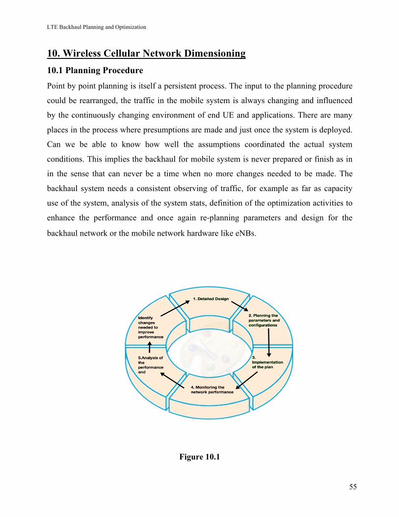
LTE Backhaul Planning and Optimization
55
10. Wireless Cellular Network Dimensioning 10.1 Planning Procedure
Point by point planning is itself a persistent process. The input to the planning procedure
could be rearranged, the traffic in the mobile system is always changing and influenced
by the continuously changing environment of end UE and applications. There are many
places in the process where presumptions are made and just once the system is deployed.
Can we be able to know how well the assumptions coordinated the actual system
conditions. This implies the backhaul for mobile system is never prepared or finish as in
in the sense that can never be a time when no more changes needed to be made. The
backhaul system needs a consistent observing of traffic, for example as far as capacity
use of the system, analysis of the system stats, definition of the optimization activities to
enhance the performance and once again re-planning parameters and design for the
backhaul network or the mobile network hardware like eNBs.
Figure 10.1
LTE Backhaul Planning and Optimization
56
10.1.1 To make this design work we need below things: -
• Selection of transport resiliency mechanisms: equipment protection, link protection,
routing/path resiliency, geo-redundancy.
• Network topology and selection of transport media such as copper, Ethernet, fiber
(Ethernet, SDH), microwave Ethernet radio.
• Definitions of QoS and availability target per traffic type
• Dimensioning backhaul bandwidths based on information of the mobile traffic and
network topology
• Planning the site solution based on information of the different radio access
technologies sharing the base station site
• Logical networking: flat network for all different traffic types or separated routing, e.g.
for user and control plane traffic and O&M traffic
• IP sub netting and routing design considering necessary traffic differentiation and
possible extension of the network
• Security design: IPsec, PKI solutions, centralized user account control, O&M security
• Selection of synchronization method and design
• Management system connectivity or use of self-organizing network (SON) functionality
like auto-connection.
The list is long and the tasks are challenging having dependencies between them.
Additionally, the following details should be considered when making the planning
decisions:
• Management network planning for transport network equipment
• Design for scalability and future-proof upgradability, transport hardware selection to
match and interoperate with selected transport features
• Migration planning, how to migrate from hybrid TDM/IP to all-IP transport network in
a cost-efficient way
• Planning for SON features, self-configuration functionality such as ANR
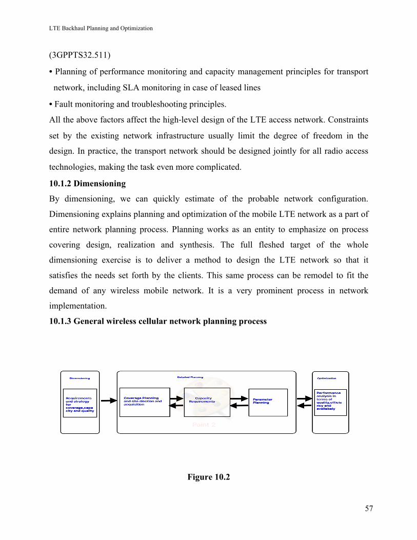
LTE Backhaul Planning and Optimization
57
(3GPPTS32.511)
• Planning of performance monitoring and capacity management principles for transport
network, including SLA monitoring in case of leased lines
• Fault monitoring and troubleshooting principles.
All the above factors affect the high-level design of the LTE access network. Constraints
set by the existing network infrastructure usually limit the degree of freedom in the
design. In practice, the transport network should be designed jointly for all radio access
technologies, making the task even more complicated.
10.1.2 Dimensioning
By dimensioning, we can quickly estimate of the probable network configuration.
Dimensioning explains planning and optimization of the mobile LTE network as a part of
entire network planning process. Planning works as an entity to emphasize on process
covering design, realization and synthesis. The full fleshed target of the whole
dimensioning exercise is to deliver a method to design the LTE network so that it
satisfies the needs set forth by the clients. This same process can be remodel to fit the
demand of any wireless mobile network. It is a very prominent process in network
implementation.
10.1.3 General wireless cellular network planning process
Figure 10.2
LTE Backhaul Planning and Optimization
58
Above Figure describes the wireless cellular system planning exercise and the state of
dimensioning in the full process. Dimensioning practice provide an estimate which is
then can be used for detailed planning of the network architecture. After the network gets
fully planned, network parameters can be optimized maximizing the efficiency of the
network.
The all dimensioning is rooted on a group of input parameters so that result produce by it
should be relevant for that given input parameters only. These parameters comprised area
under taken, expected flowing traffic and needed QoS. It provides the growth of the
needs for network architecture. Dimensioning utilizations generally easier models for
displaying of the genuine conditions when contrasted with the detailed planning. More
straightforward models and strategies decrease the time needed for dimensioning.
Dimensioning uses for the most part more clear models for showing of the veritable
conditions when appeared differently in relation to the definite arranging. On the other
hand, dimensioning device should to be sufficiently precise to provide outputs with an
acceptable accuracy level, when stacked with an expected data traffic profile and client
base.
References: -
[1] http://lib.tkk.fi/Dipl/2009/urn100056.pdf
[2] www.ericsson.com- Documents
LTE Backhaul Planning and Optimization
59
11. LTE Objective: - 11.1 The Major objectives are given below:
Wireless LTE architecture dimensioning is straightforwardly related to the viability and
the quality of the network, and it can deeply influence its advancement.
11.1.1 LTE Dimensioning Procedure
LTE Dimensioning procedure begins with the Radio Link Budget outputs, used to decide
the maximum data path loss. The consequence of this progression relies on the
propagation models used. The estimated cell size, got in this progression, leads to the
maximum permitted cell size. This parameter is utilized to compute the cells count in the
zone of interest. Thus, it comes up with a rough idea of the needed count of eNBs.
Wireless network dimensioning takes these essential steps:
• Data or Traffic Analysis
• Estimation of coverage for the network
• Evaluating Capacity
• Dimensioning of Transport dimensioning
11.1.2 Data and Traffic observations: -
This is the first phase in dimensioning of LTE. It includes collecting of needed
information sources and their analysis to make them ready for use in LTE dimensioning
procedure. Operator data and prerequisites are analyzed to decide the best framework
design.
The other possibility is to stay with a gathering of setups and do dimensioning for every
parameter to decide the most reasonable decision for example, this may include picking
up two or 3 different LTE channel bandwidths for analysis.
LTE Backhaul Planning and Optimization
60
11.1.3 Traffic Analysis: -
Traffic request is breaking down to get the most ideal system arrangement with least
supplies. In this project, three sorts of activity are considered for LTE. They are VoIP,
browsing and streaming. Overhead because of higher layers is considered when we
calculate the net data bit rate for these kinds of traffic. Peak hour traffic is utilized rather
than average values. Similarly, demand for various services need to be considered.
11.1.4 Estimation of coverage for the network
Coverage analysis generally remains the most important step in the plan of LTE system
as with 3G network. RLB (Radio Link Budget) is at the main part of coverage planning,
which permits the testing of data path loss model and the needed peak data rates opposite
to the target coverage levels. The outcome is the successful cell site range to work out
with the coverage-limited site number. This needs the selection of suitable propagation
model to estimate path loss. This estimate depends on coverage needs and should be
checked for the capacity demands. With the information of cell size estimate and of the
region to be covered, an estimate of the aggregate number of site is found.
11.1.5 Evaluating Capacity
Having a rough idea of the size of cell and site number, verification of coverage analysis
is completed for the needed capacity. In LTE, the primary indicator of capacity is SINR
distribution in the cell. This distribution is acquired via completing system level
simulations. It is checked, if with the provided site’s density, the network can carry the
predefined load or new sites must be added.
LTE cell site capacity is affected by a few variables such as, antenna configurations,
packet scheduler execution, supported MCSs (Modulation and coding scheme) and all
interference levels. Hence, for complete analysis, many groups of simulation results are
needed. Capacity based site number and coverage result are to be compared and larger of
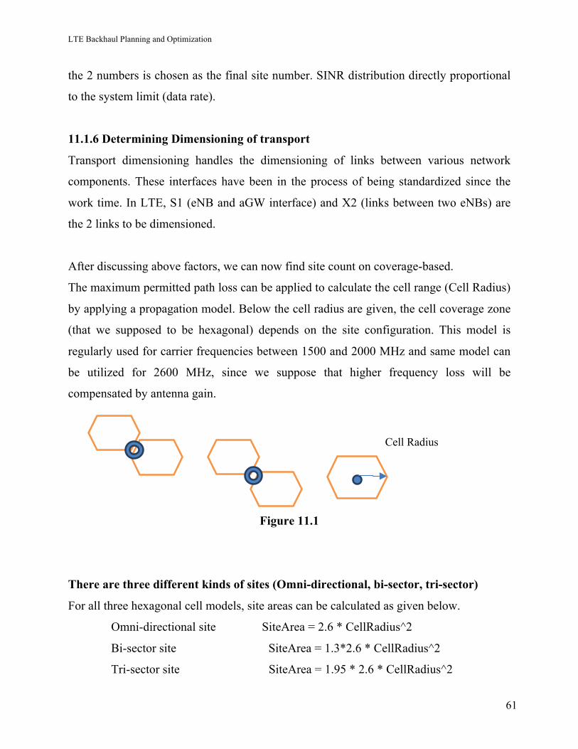
LTE Backhaul Planning and Optimization
61
the 2 numbers is chosen as the final site number. SINR distribution directly proportional
to the system limit (data rate).
11.1.6 Determining Dimensioning of transport
Transport dimensioning handles the dimensioning of links between various network
components. These interfaces have been in the process of being standardized since the
work time. In LTE, S1 (eNB and aGW interface) and X2 (links between two eNBs) are
the 2 links to be dimensioned.
After discussing above factors, we can now find site count on coverage-based.
The maximum permitted path loss can be applied to calculate the cell range (Cell Radius)
by applying a propagation model. Below the cell radius are given, the cell coverage zone
(that we supposed to be hexagonal) depends on the site configuration. This model is
regularly used for carrier frequencies between 1500 and 2000 MHz and same model can
be utilized for 2600 MHz, since we suppose that higher frequency loss will be
compensated by antenna gain.
Figure 11.1
There are three different kinds of sites (Omni-directional, bi-sector, tri-sector)
For all three hexagonal cell models, site areas can be calculated as given below.
Omni-directional site SiteArea = 2.6 * CellRadius^2
Bi-sector site SiteArea = 1.3*2.6 * CellRadius^2
Tri-sector site SiteArea = 1.95 * 2.6 * CellRadius^2
Cell Radius
LTE Backhaul Planning and Optimization
62
And as it is site’s count to be implemented can be easily find out the calculations from
the input value of the deplying area and Cellarea
NumSitesCoverage = DeploymentArea/SiteArea
The Traffic demand idea and Overbooking factor explanation
As the given frequency bandwidth can just convey a specific measure of capacity, then
the data traffic request requires to be understood. The difficult section is the examination
of the peak busy hours of various subscriber kinds and traffic profiles. The required
outcome is the overbooking factor that depicts the level of the multiplexing or or users
sharing a provided channel, client’s count or capacity range.
The main inputs for estimation are listed here
• Subscriber Density
• Peak and the Average Data Rate
• Data Volume per User
• The traffic mix and busy hour analysis
• Daily Traffic Profiles
Since we are coverage planning, likewise capacity planning is done independently for
various service areas (urban, rural and suburban).
If we use requirements relating to the traffic of peak hours, then it will lead to over-
dimensioning. Valuable resources could be wasted in rest of the day hours and network
expenditure will go remarkably higher. Consequently, OBF is the average client’s count
that can share a given unit of channel. Peak data rate dimensioning by using the channel
unit. For 100% channel loading, after that the OBF is simply equivalent to the proportion
between the peak and the average rates (PAR).
However, network dimensioned with 100% traffic load is not safe. Hence, the parameter
utilization factor is introduced. In common data networks, to assure the Quality of
Service (QoS) utilization factor is < 85%. Consequently, the higher this parameter, we
LTE Backhaul Planning and Optimization
63
will find the longer average waiting time for clients getting to the channel. Therefore, the
overbooking element is derived as given below: -
Overbooking Factor = Peak to Average Ratio*Utilization Factor
Capacity based number of sites
Considering the help of traffic requirement estimation and the factors that are involved in
it, we will calculate the overall required data rate. As overbooking factor explained above
the whole data rate capacity will be calculated.
Overall Data Rate = Number of Users*Peak Data Rate*Overbooking Factor
So, to support above calculated total traffic, here is the formula for site’s count.
Number of Sites Capacity = Overall Data Rate /Site Capacity
As the demand gets high and more clients are included to the network services, the
capacity based site number takes the lead and then more smaller cells like Pico, micro are
needed. The bigger of the 2 counts is finally used as a output of dimensioning. The
number of site is performed for every sort of area as done for coverage evolution. In a
completely functional network capacity based site’s number is commonly higher than the
coverage based counterpart
Dimensioning Output
By taking all above in consideration, we can get the dimensioning outputs, which are
calculated by using the data from previous given data. By getting these all outputs, a LTE
network can be created and that network can be optimized for better performance which
will be discussed in the LTE optimization part. As the network, will be in use, it will tell
about the network performance and we can do amendments in the network according to
our requirement.
LTE Backhaul Planning and Optimization
64
Below are the points takes in to count to creating a network: -
• Statistics of Population
• Subscriber’s number
• Area needs to cover by the mobile network
• Geographical spreading of subscriber
• Cell Throughput of the network
• Capacity-based site’s counting
By observing Population stats help to tell, the whole population and person’s number per
household who are going to utilize the service. By using simple criteria that one client or
user per household, the subscribers number can be calculated. This number obtains by
dividing the whole population by number of persons per household.
Number of Households = Total Population/Number of Persons in Household
In the real time, existing subscriber’s number using the service is always lower than the
whole household’s number. Therefore, actual subscriber count can be estimated and as
the network is start operating we can add the capacity to the network for the better
performance. It also depends that what type of services are to be used by the customers.
References: -
[1] http://lib.tkk.fi/Dipl/2009/urn100056.pdf
[2] https://www.slideshare.net/AshrafElSharif/report-final-46056616
[3] https://www.scribd.com/document/78550096/LTE-Planning
[4] http://docplayer.net/11419404-Dimensioning-of-lte-network-description-of-models-and-tool-
coverage-and-capacity-estimation-of-3gpp-long-term-evolution-radio-interface.html
LTE Backhaul Planning and Optimization
65
12. Carrier aggregation and MBH tiers in LTE 12.1 Carrier Aggregation: -
Carrier aggregation (CA) permits up to five LTE Release 8 perfect component carriers
being joined, each having a bandwidth of 1.4 MHz to 20 MHz and giving a most extreme
of 100 MHz aggregated bandwidth, and gives practically as high a range effectiveness
and peak rates as single allocation does.
CA can be deployed either intra-band, which means the component carriers belong to the
same operating frequency band, or inter-band, which means the component carriers
belong to different operating frequency bands.
On the other hand, scheduling a high number of users over multiple carriers provides
only marginal gain. Improving average cell throughput both in UL and DL practically
means needing a higher backhaul bandwidth. With current approaches CA does not affect
the synchronization and backhaul latency requirements; however, lower RTT (round trip
time) is preferred to be able to fully utilize the higher data rates for single users.
The capacity of CA to enhance single user throughput relies upon the numbers of the user
in a cell. If users number is low, scheduling over different carriers gives huge throughput
gain since the available radio recourses can be distributed to the user(s) with the best
radio conditions (e.g. different propagation characteristics of different frequency bands).
Then again,
scheduling a high number of users over multiple carriers gives just minimal gain.
Enhancing normal cell throughput both in UL and DL practically means requiring a
higher backhaul bandwidth. With current methodologies CA does not affect the
synchronization and backhaul latency requirements; but bring down RTT (round trip
time) is preferred to be able to fully utilize the higher data rates for single users.
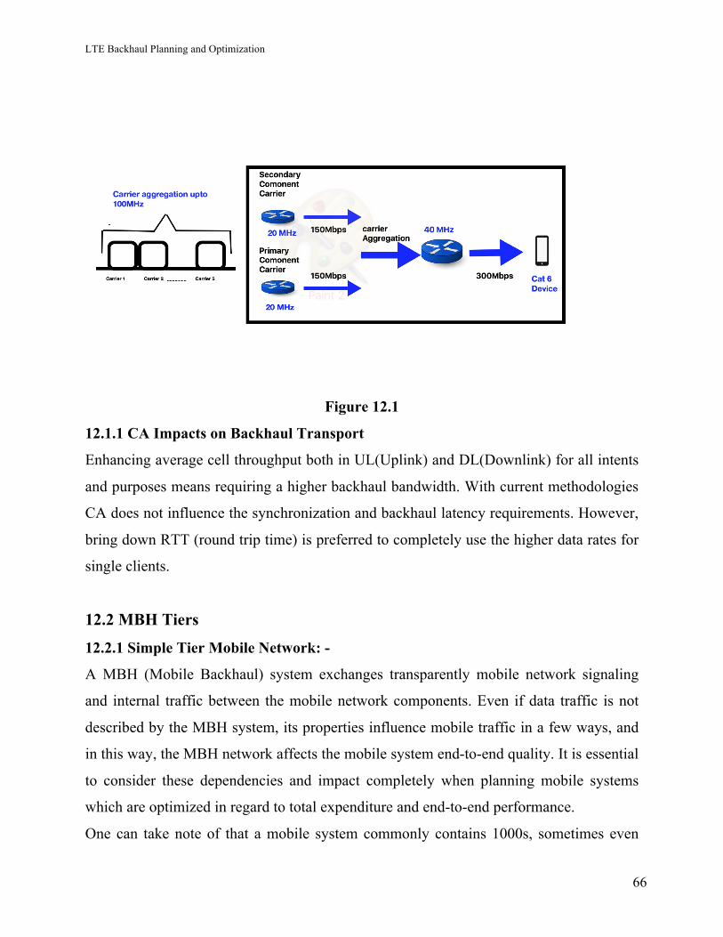
LTE Backhaul Planning and Optimization
66
Figure 12.1
12.1.1 CA Impacts on Backhaul Transport
Enhancing average cell throughput both in UL(Uplink) and DL(Downlink) for all intents
and purposes means requiring a higher backhaul bandwidth. With current methodologies
CA does not influence the synchronization and backhaul latency requirements. However,
bring down RTT (round trip time) is preferred to completely use the higher data rates for
single clients.
12.2 MBH Tiers
12.2.1 Simple Tier Mobile Network: -
A MBH (Mobile Backhaul) system exchanges transparently mobile network signaling
and internal traffic between the mobile network components. Even if data traffic is not
described by the MBH system, its properties influence mobile traffic in a few ways, and
in this way, the MBH network affects the mobile system end-to-end quality. It is essential
to consider these dependencies and impact completely when planning mobile systems
which are optimized in regard to total expenditure and end-to-end performance.
One can take note of that a mobile system commonly contains 1000s, sometimes even
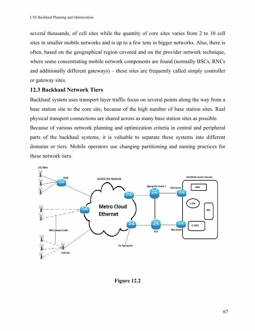
LTE Backhaul Planning and Optimization
67
several thousands, of cell sites while the quantity of core sites varies from 2 to 10 cell
sites in smaller mobile networks and is up to a few tens in bigger networks. Also, there is
often, based on the geographical region covered and on the provider network technique,
where some concentrating mobile network components are found (normally BSCs, RNCs
and additionally different gateways) – these sites are frequently called simply controller
or gateway sites.
12.3 Backhaul Network Tiers
Backhaul system uses transport layer traffic focus on several points along the way from a
base station site to the core site, because of the high number of base station sites. Real
physical transport connections are shared across as many base station sites as possible.
Because of various network planning and optimization criteria in central and peripheral
parts of the backhaul systems, it is valuable to separate these systems into different
domains or tiers. Mobile operators use changing partitioning and naming practices for
these network tiers.
Figure 12.2
LTE Backhaul Planning and Optimization
68
There are distinctive models for the LTE organize topology, But Here we will use end to
end Layer 3 Solution in the LTE network deployment. In this, all traffic will be sent in
various VPNs and is routing as indicated by their IP address. The X2( the link between
eNodeBs ) traffic can be forwarded on an aggregate router. All S1, X2 connections will
be designed in the same L3VPN.
HUB: - X2 connectivity to neighbor eNBs is, rather than direct X2 connection, today
generally arranged by means of a higher network tier hub point indicate back the
neighbor eNB (known as hair-pinning). Subsequently all kinds of traffic from the eNBs
regularly travel together at least until this hub point.
References: -
[1] MOBILE BACKHAUL -EDITORS Esa Metsa ̈la ̈ Juha Salmelin, Nokia Siemens
Networks, Finland
[2] LTE Carrier Aggregation Technology development and deployment worldwide – 4G
Americans.https://www.scribd.com/document/291952620/4G-Americas-Carrier-
Aggregation-FINALv1-0-3
[3] http://www.radio-electronics.com/info/cellulartelecomms/lte-long-term-evolution/4g-
lte-advanced-carrier-channel-aggregation.php
[4]http://www.3gpp.org/technologies/keywords-acronyms/101-carrier-aggregation-
explained
[5] Guidelines for LTE Backhaul Traffic Estimation by NGMN Alliance
LTE Backhaul Planning and Optimization
69
13. Network Deployment 13.1 LTE Backhaul Network Implementation on the City
Link bandwidth dimensioning formulas are most helpful for aggregate connection
dimensioning. The first mile data bandwidth, to be discussed first, is regularly chosen
large enough so that no QoS criteria require to be considered.
Initially, we must figure the dimension necessities for the network. the calculations
required for dimensioning the last mile, and the calculations to choose the bandwidth
required for LTE mobile backhaul network.
First Mile: -
The application of a hypothetical bandwidth dimensioning formula regularly results in a
connection bandwidth that is less than twice the average traffic demand. For example, for
half load the normal DL (Downlink) throughput of a 20 MHz urban 2x2 MIMO LTE site
(three cells) would be 40–60 Mbps. Picking the first mile bandwidth capacity of 100
Mbps would henceforth well satisfy the site average traffic request, with a heavy margin
for signaling traffic. On the other hand, with 100 Mbps first mile interface bandwidth, a
single class 4 UE in excellent radio conditions would not have the capacity to achieve its
full supported bit rate of 150 Mbps because of restricted transport bandwidth. Thus, it has
turned into a typical practice among operators to choose the first mile bandwidth on the
basis of the cell peak rate, as opposed to the site average traffic demand. All things
considered, if the first mile transport restricts the cell peak rate there would not be much
sense in putting resources into peak rate improving radio features either (e.g. LTE-A
carrier aggregation). Supporting cell peak rate may not be feasible or economical at all
sites.
A few heuristic guidelines can be considered for first mile bandwidth dimensioning,
including:
• Choose the first mile bandwidth as the cell peak rate.
• Choose the first mile bandwidth as site average bandwidth.
LTE Backhaul Planning and Optimization
70
• Choose the first mile bandwidth as the maximum of cell peak rate and site BH average
bit rate.
• Choose the first-mile bandwidth as the cell peak rate of one cell plus the average BH
traffic of the remaining cells.
• Choose the first-mile bandwidth as the cell peak rate times the number of cells. S1
transport overhead should be added to the result.
The disadvantage of such rules of thumb is that they do not consider any QoS criteria.
Then again, since the resulting allocation is generally many times the average traffic
request, any QoS criterion of interest is automatically fulfilled. Yet, mapping
delay-sensitive traffic to a queue with strict priority is prescribed to avoid unpredictable
delay peaks because of incidental high peak rate clients.
In this system execution, we will utilize LTE data limit is settled per site—free of a
number of clients or handsets controlled by the base station and channel data
transmission. This can be expanded by including more cell locales or expanding LTE
channel data bandwidth. Including more macro cell sites would essentially build organize
operations cost. Picocells with more financially savvy backhaul alternatives are a decent
bargain for the LTE network.
While a backhaul capacity limit of 150 Mbit/s for a three-sector site with 20Mhz LTE
channels is below some LTE backhaul claims, let us suppose we need to run an LTE
network in the Edmonton city of Canada for 30000 peoples living here. With using 20
Mhz frequency and 2X2 antenna we can give 150 Mbps download speed for one cell
which will go to 120Mbps for the peak speed. With 20MHz bandwidth spectrum and 2X2
MIMO with 2 carriers running on it, each site can take up to 1000 users simultaneously.
We need 30 sites for the whole Edmonton city as per the calculations.
From eNodeB to the access node, we will use fiber in busy areas for example in
downtown and urban areas etc. and can use the microwave in rural areas as there are not
so many people who use LTE services. Microwave transmission media will save the cost
LTE Backhaul Planning and Optimization
71
of implementation and equipment.
From aggregation node to the core node we need fiber only because this network should
be reliable and delays would be eradicated at this part.one more point to use only fiber is
this part of the network requires more capacity and fiber can be available for high
capacity as well. No doubt the price of fiber deployment will go high but the benefits we
get from fiber will compensate the expenditure on fiber.
We will be required some Pico or Femto cell as well where the city shows more traffic.
After deployment, we can analyze the network and check whether we require putting
more macro, micro, pico or femto cell to make network work reliable.
The diagram shown below will tell us the location for eNodeB and small cells as I have
put these all according to my assumption. Mostly, an eNodeB can serve at least 1000
users and as I am taking only 30000 people there should be only 30 sites but we cannot
do that because we need to provide coverage to the whole city so we are using sites
according to the area of the city of Edmonton.
The areas where small cells have been used, are more congested (Assumed) means more
people density such as downtown and urban areas and the other areas are the mostly rural
area.
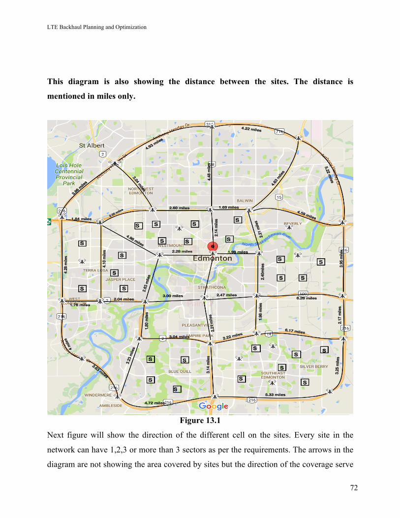
LTE Backhaul Planning and Optimization
72
This diagram is also showing the distance between the sites. The distance is
mentioned in miles only.
Figure 13.1
Next figure will show the direction of the different cell on the sites. Every site in the
network can have 1,2,3 or more than 3 sectors as per the requirements. The arrows in the
diagram are not showing the area covered by sites but the direction of the coverage serve
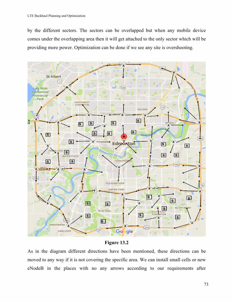
LTE Backhaul Planning and Optimization
73
by the different sectors. The sectors can be overlapped but when any mobile device
comes under the overlapping area then it will get attached to the only sector which will be
providing more power. Optimization can be done if we see any site is overshooting.
Figure 13.2
As in the diagram different directions have been mentioned, these directions can be
moved to any way if it is not covering the specific area. We can install small cells or new
eNodeB in the places with no any arrows according to our requirements after
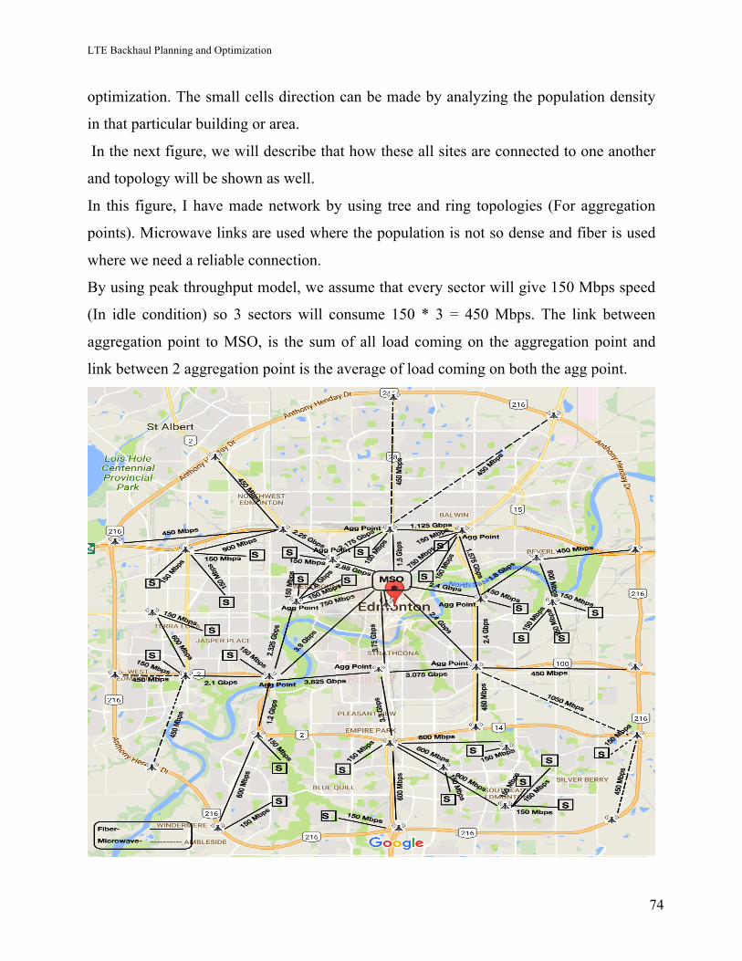
LTE Backhaul Planning and Optimization
74
optimization. The small cells direction can be made by analyzing the population density
in that particular building or area.
In the next figure, we will describe that how these all sites are connected to one another
and topology will be shown as well.
In this figure, I have made network by using tree and ring topologies (For aggregation
points). Microwave links are used where the population is not so dense and fiber is used
where we need a reliable connection.
By using peak throughput model, we assume that every sector will give 150 Mbps speed
(In idle condition) so 3 sectors will consume 150 * 3 = 450 Mbps. The link between
aggregation point to MSO, is the sum of all load coming on the aggregation point and
link between 2 aggregation point is the average of load coming on both the agg point.
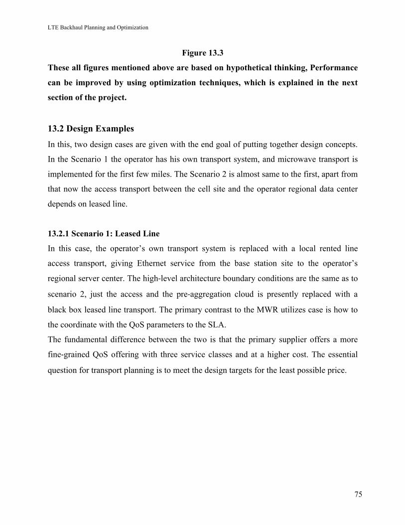
LTE Backhaul Planning and Optimization
75
Figure 13.3
These all figures mentioned above are based on hypothetical thinking, Performance
can be improved by using optimization techniques, which is explained in the next
section of the project.
13.2 Design Examples
In this, two design cases are given with the end goal of putting together design concepts.
In the Scenario 1 the operator has his own transport system, and microwave transport is
implemented for the first few miles. The Scenario 2 is almost same to the first, apart from
that now the access transport between the cell site and the operator regional data center
depends on leased line.
13.2.1 Scenario 1: Leased Line
In this case, the operator’s own transport system is replaced with a local rented line
access transport, giving Ethernet service from the base station site to the operator’s
regional server center. The high-level architecture boundary conditions are the same as to
scenario 2, just the access and the pre-aggregation cloud is presently replaced with a
black box leased line transport. The primary contrast to the MWR utilizes case is how to
the coordinate with the QoS parameters to the SLA.
The fundamental difference between the two is that the primary supplier offers a more
fine-grained QoS offering with three service classes and at a higher cost. The essential
question for transport planning is to meet the design targets for the least possible price.
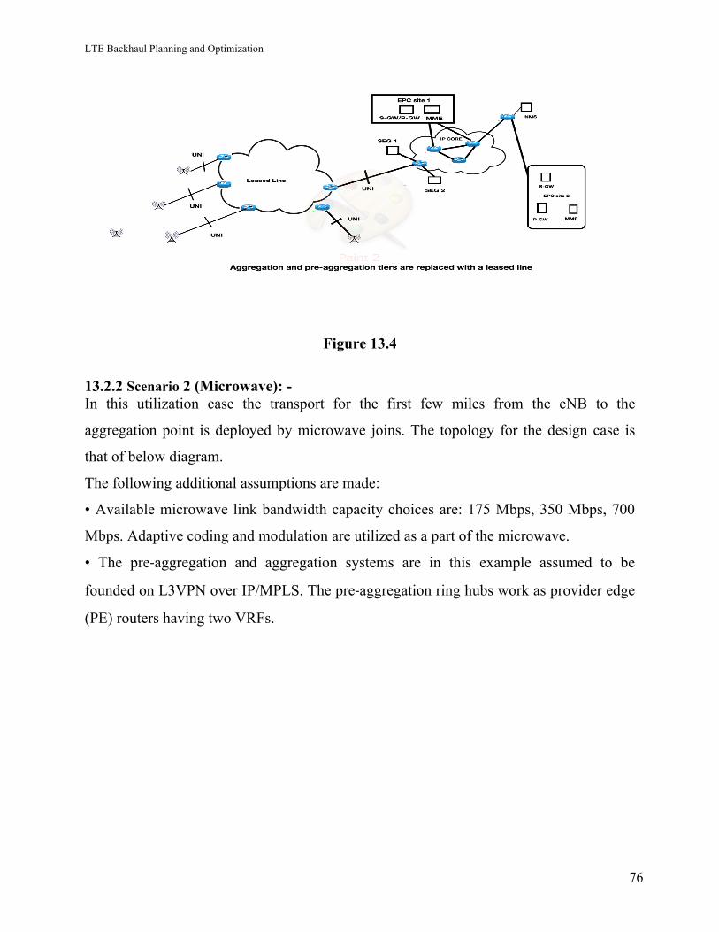
LTE Backhaul Planning and Optimization
76
Figure 13.4
13.2.2 Scenario 2 (Microwave): - In this utilization case the transport for the first few miles from the eNB to the
aggregation point is deployed by microwave joins. The topology for the design case is
that of below diagram.
The following additional assumptions are made:
• Available microwave link bandwidth capacity choices are: 175 Mbps, 350 Mbps, 700
Mbps. Adaptive coding and modulation are utilized as a part of the microwave.
• The pre-aggregation and aggregation systems are in this example assumed to be
founded on L3VPN over IP/MPLS. The pre-aggregation ring hubs work as provider edge
(PE) routers having two VRFs.
LTE Backhaul Planning and Optimization
77
Figure 13.5. Topology of Design Example
Bandwidth Dimensioning
The above traffic model is given as: -
This, in terms of traffic information, is extremely insignificant however on the other hand
shows a typical traffic model available in the design phase. The input necessities
additionally state that the system must have the capacity to support a peak cell data rate
of 20 MHz + 10 MHz carrier aggregation, which with 10% transport overhead relates to a
peak rate of 250 Mbps per cell. From this "the very beginning" requirement, it takes after
that the first mile microwave connection should to be 350 Mbps; with such high peak rate
detailed first mile dimensioning becomes unnecessary since the site average piece rate of
40 Mbps is just a small fraction of this. The fascinating question is mostly whether 350
LTE Backhaul Planning and Optimization
78
Mbps is also enough for the second microwave hop that serves three eNBs.
Looking at the illustration topology for the second hop, the average traffic carried is 120
Mbps of information and 150 Erlangs of voice (three eNBs). Generally, voice and data
BHs do not concur however for simplicity’s purpose both BHs are assumed here to take
place at the same time. For voice, the probability that the voice call’s count exceeds 170
is 1%, from the Erlang-B recipe for 150 Erlangs of offered voice traffic. The bandwidth
capacity for 170 voice calls with IPsec headers is ≈ 15 Mbps. The aggregate of signaling
and voice is still under 5% of the total link bandwidth
To estimate the effective throughput reduction experienced by TCP download the
segment of signaling and voice traffic is subtracted from the connection capacity, leaving
≈ 330 Mbps as the effective pipe for data, adjusted down to the closest 10 Mbps. It is
important to know the parameter R in the M/G/R-PS equation, which is different of most
extreme TCP data rate constrained via an air interface. This is frequently the most
difficult part, since the TCP peak rate relies on upon several factors, including radio
conditions and the quantity of different clients in the cell. Cranking out some example
numbers for a 10-Mbps, 30-Mbps and-50 Mbps UE peak rate (with rounding down, R =
33, 10, 6).
References: -
[1] MOBILE BACKHAUL by EDITORS Esa Metsa ̈la ̈ and Juha Salmelin ,Nokia
Siemens Networks, Finland
[2] BOOK--LTE Backhaul planning and optimization by Esa Markus Metsälä and Juha
T.T. Salmelin ,Nokia Networks, Espoo, Finland
[3] Guidelines for LTE Backhaul Traffic Estimation by NGMN Alliance
[4] SMD203_Samsung_LTE_RAN_System_Description_R1_0_0 by Samsung
[5] Google Maps
LTE Backhaul Planning and Optimization
79
14. LTE Network Optimization As we have created a network for the whole city, now people will use the network and in
running network we face so many issues. These issues can be any types and can degrade
network performance. Next part of the project also demonstrates how the network can be
optimized at its best while there were issues pertaining to KPI degradation, Coverage
black spots. These operational issues can be cropped up during any point of time due to
reasons like site OOS (Out of service), backhaul/transmission issue, bouncing busy hour
(BBH) traffic, specific event going on at particular location, Bad RF conditions, alarms
on the site, and new building constructed opposite to the site affecting LOS (Line of
Sight) etc.
These all above mentioned issues result into poor network health which leads to customer
dissatisfaction.We will now discuss various parameters and assumptions related to the
design and discuss how these parameters affect the planning and can affect optimization.
Below are the major network key performance indicators (KPI’s) which deteriorate the
overall network health& by improving / avoiding below failures network health can be
optimized. We will discuss every issue in detail and will give solution for those problems.
14.1 Accessibility or CFR (Call Failure Rate): -
When UE wants to access the channel but, it is not able to. In Other terms, it is a
measure of the ability of a user to obtain an E-RAB from the system.
Before explaining accessibility, we will understand about few steps that UE (User
equipment) goes through to punch in the accessibility phase.
• UE is OFF.
• UE gets power on.
• Then UE searches the frequency to latch on.
• Time and frame synchronization and cell search.
• Then it does MIB (Master Information Block- An important message that is
broadcast by eNodeB irrespective of any user presence) and SIB (System
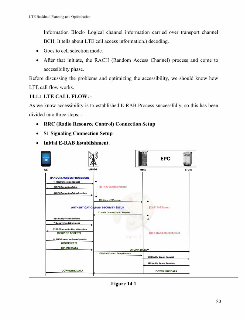
LTE Backhaul Planning and Optimization
80
Information Block- Logical channel information carried over transport channel
BCH. It tells about LTE cell access information.) decoding.
• Goes to cell selection mode.
• After that initiate, the RACH (Random Access Channel) process and come to
accessibility phase.
Before discussing the problems and optimizing the accessibility, we should know how
LTE call flow works.
14.1.1 LTE CALL FLOW: -
As we know accessibility is to established E-RAB Process successfully, so this has been
divided into three steps: -
• RRC (Radio Resource Control) Connection Setup
• S1 Signaling Connection Setup
• Initial E-RAB Establishment.
Figure 14.1
LTE Backhaul Planning and Optimization
81
These all three steps have been shown in the call flow diagram given above. It shows us
when and how these get done.
a) S1 Establishment: -
In this eNodeB sends a message to MME that is called “initial UE message” to do
authentication with MME and to configure EUTRAN security function. Subsequently,
MME communicates with P-GW via S-GW to get IP information for eNodeB with
“initial context setup message”. Later S1 connection establishes successfully.
b) E-RAB (Radio Access Bearer) Establishment: -
So “initial context setup message” contains “Attach accept” and “Activate Default
Bearer Request” messages in it. This also informs maximum UL/DL and eNodeB sets
up radio resources accordingly. Then UE received the message “RRC Connection
Reconfiguration” sent by eNodeB which brings “Attach Accept” message as payload.
This has EPS Radio Bearer Identifier data with it to activate default bearer. After this
“RRC Connection Reconfiguration Complete” message transmitted to eNodeB by UE.
So ultimately, eNodeB sent “initial context setup response” message to MME. This
message holds the address of eNodeB used for DL traffic on S1_user plane reference
point.
14.2 Accessibility Problems: -
14.2.1 Accessibility Issues in RRC Phase and Solutions: -
a) Issue: - Accessibility issue in RRC phase indicates towards poor RF conditions, bad
RRU (Radio Resource Unit) or UE (User Equipment) trying to access the network in bad
conditions.
Solution: - We can try to ameliorate RF conditions by tuning RSRP (Reference Signal
Received Power), RSRQ (Reference Signal Received Quality) and SINR (Signal to
Interference & Noise Ratio). If RRU is not working fine, we can replace it.
LTE Backhaul Planning and Optimization
82
b) Issue: - Sometimes eNodeB gives bad coverage to the user. This could be happened
due to bad RRU, due to any hardware issue, by antenna tilt displacement etc.
Solution: - By adjusting tilt or changing the RRU, this problem can be solved. We can
also check UL RSSI.
c) Issue: -Sometime UE tries to access network in bad coverage so that’s why
accessibility drop rate increased.
Solution: - There is counter available which tells if any block happens due to UE and
IMEI number can be found on this counter and we can resolve the issue for that particular
UE.
d) Issue: - Sometimes block pegs due to high load or overload circumstances.
Solution: - Check specific counter for that if pegging than we can check with the
capacity of the site and resolve the issue.
e) Issue: - Blocking due to wrong cell parameters setup.
Solution: - Match the parameters of the cell with the standard or golden parameters.
f) Issue: - Sometimes UE gets camping with the wrong cell.
Solution: - Tune the cell reselection parameters on the site or check nearby sites if they
are in prelaunch or any testing or troubleshooting going on that site.
14.2.2 Accessibility Issues in S1 Phase and Solutions: -
a) Issue: - Sometime TAI (Tracing Area Identifier) and LAI (Location Area Identifier)
pairing is incorrect or missing which causes the accessibility failure in the network.
Solution: - Check transport related issues and get the link up.
14.2.3 Accessibility Issues In E-RAB Phase and Solutions: -
a) Issue: - Calls get blocked in the execution phase.
Solution: - Usually happens due to hanging resources in the eNodeB or RRU issue.
Restart the eNodeB if does not help then try to replace the RRU. Sometimes the problem
comes due to UE issue too. To find out UE issue, we need to analyze CTR & MME.
LTE Backhaul Planning and Optimization
83
14.3 Retainability or CDR (Call Drop Rate)- The ability of a user to retain its
requested service once connected for the desired duration. LTE drop calls can be
majorly due to Poor radio conditions.
This rate can be measure by the KPI given below: -
14.3.1 Retainability Issues and Solutions: -
a) Coverage Hole: -
It is the area within the network which is not covered by wireless network. It usually
happens when client SNRs falls below a predetermined level.
Generally, it is caused by physical obstructions such as buildings, hills, tunnels and
indoor parking garages.
Solution: - We can detect the coverage hole location by doing drive test and can get rid
of this by installing new cell, down or up tilt or by improving RF conditions.
b) Do check transmission power of source & neighboring site or it can be a
Neighboring site down
Solution: - Check If the neighbor site is down where we need to do a handover and make
it work for the resolution.
c) Missing neighbor relations: - Sometime handover does not occur properly because
the neighbor is not defined in another site’s neighbor list, consequently drop happens on
site and degrade the performance.
Solution: - Check the neighbor list of the site and add nearby neighbors if anyone of
them is missing.
d) Incorrectly set handover parameters: - Sometime parameters are not set accurately.
Due to which drop can happen.
Solution: - Check handover parameters on the site and make them same as the golden
parameters.
e) Admission rejects, due to lack of licenses on target site PCI/RSI Collision or
PCI/RSI Confusion: - Admission rejection happens when PCI (Physical Cell Identifier)
or RSI (Root Sequence Indicator) have some mismatch or used repeatedly.
LTE Backhaul Planning and Optimization
84
Solution: - Check if PCI or RSI is repeated then remove the error.
f) UL RSSI issue on self or neighboring site: -
Solution: - If there is any mismatch between standard RSSI on the site. Make it as a
golden parameter to resolve the issue.
g) Hardware /RRH issue: - Hardware issues for example: - RRU, Antenna etc. are not
working properly. Sometime any cable connection is loose.
Solution: - Need to replace RRU or antenna or check the cable connection.
14.4 Hand off Failures: -
14.4.1 Mobility: Introduction
• Mobility defines the capability of the system to allow movement within the LTE
network.
• A common mobility measurement is LTE handover success rate.
14.4.2 Handover: -
• The process of transferring an ongoing call or data session
• HO can be Intra Frequency or inter frequency.
14.4.3 Handover types Explained:
• Intra eNB: - HO between sectors of the same eNB.
• Inter eNB: - HO between two different eNBs.
There are two general types of handovers in LTE.
a) X2 handover: - In LTE eNodeBs are connected with the interface called as X2. If
same MME is serving to two eNodeBs, handover will be taken place from the source to
the target eNodeB over the X2 link.
b) S1 Handover: - UE is handed over using an S1 handover if the X2 interface is not
available between the source and target eNodeB or source and target belong to different
MME.
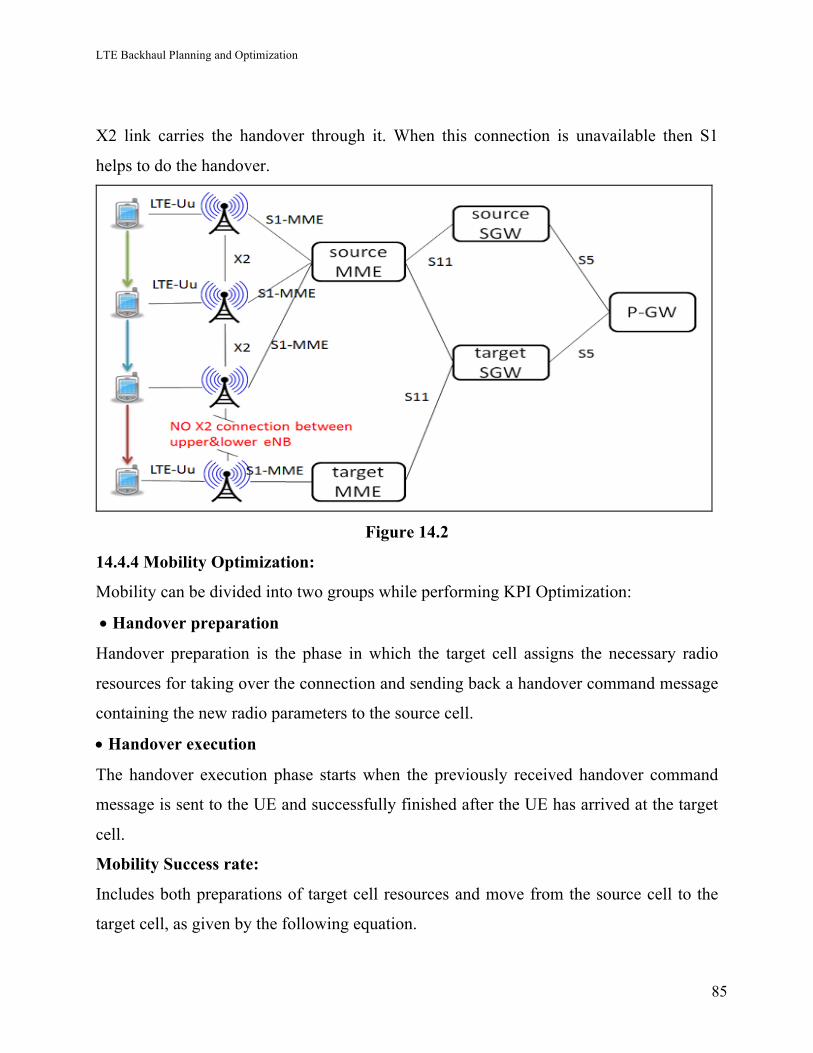
LTE Backhaul Planning and Optimization
85
X2 link carries the handover through it. When this connection is unavailable then S1
helps to do the handover.
Figure 14.2
14.4.4 Mobility Optimization:
Mobility can be divided into two groups while performing KPI Optimization:
• Handover preparation
Handover preparation is the phase in which the target cell assigns the necessary radio
resources for taking over the connection and sending back a handover command message
containing the new radio parameters to the source cell.
• Handover execution
The handover execution phase starts when the previously received handover command
message is sent to the UE and successfully finished after the UE has arrived at the target
cell.
Mobility Success rate:
Includes both preparations of target cell resources and move from the source cell to the
target cell, as given by the following equation.
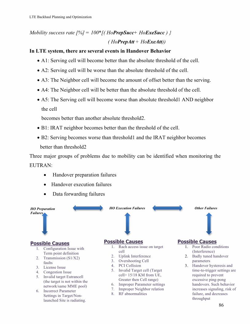
LTE Backhaul Planning and Optimization
86
Mobility success rate [%] = 100*[( HoPrepSucc+ HoExeSucc ) }
( HoPrepAtt + HoExeAtt))
In LTE system, there are several events in Handover Behavior
• A1: Serving cell will become better than the absolute threshold of the cell.
• A2: Serving cell will be worse than the absolute threshold of the cell.
• A3: The Neighbor cell will become the amount of offset better than the serving.
• A4: The Neighbor cell will be better than the absolute threshold of the cell.
• A5: The Serving cell will become worse than absolute threshold1 AND neighbor
the cell
becomes better than another absolute threshold2.
• B1: IRAT neighbor becomes better than the threshold of the cell.
• B2: Serving becomes worse than threshold1 and the IRAT neighbor becomes
better than threshold2
Three major groups of problems due to mobility can be identified when monitoring the
EUTRAN:
• Handover preparation failures
• Handover execution failures
• Data forwarding failures
HO Preparation Failures
HO Execution Failures Other Failures
Possible Causes 1. Configuration Issue with
Term point definition 2. Transmission (S1/X2)
faults 3. License Issue 4. Congestion Issue 5. Invalid target Eutrancell
(the target is not within the network/same MME pool)
6. Incorrect Parameter Settings in Target/Non-launched Site is radiating.
Possible Causes 1. Rach access issue on target
cell 2. Uplink Interference 3. Overshooting Cell 4. PCI Collision 5. Invalid Target cell (Target
cell> 15/18 KM from UE, Greater then Cell range)
6. Improper Parameter settings 7. Improper Neighbor relation 8. RF abnormalities
Possible Causes 1. Poor Radio conditions
(Interference) 2. Badly tuned handover
parameters 3. Handover hysteresis and
time-to-trigger settings are required to prevent excessive ping-pong handovers. Such behavior increases signaling, risk of failure, and decreases throughput
LTE Backhaul Planning and Optimization
87
14.4.5 HO Preparation Fail Troubleshooting and Analysis:
a) Configuration Issue with Term point definition: -
• Check Term point to MME for target cell has been defined properly. Using “st
termpointtomme” status of connected MME can be checked, whether all are up
and running, as if one is inactive, the load will be on the other MME’s in the
pool.
b) Transmission (S1/X2) faults:
• Check current alarm, Alarm history & activity logs to confirm drops due to
HW fault.
• In case of transport fault check media continuity
c) License Issue:
• Check the license state for connected user at target cell
• Check the license state for RLC UM at target cell (source and target should
have the same state for RLC Mode)
• Check the license state for Multiple E-RAB at target cell.
• Check the license state for mobility at target cell.
Solution: - Load the license required by the target cell. This could happen when there is
heavy traffic on the target. The solution is to load high capacity parameters to the target
and/or shake off some traffic from the cells with heavy traffic.
d) Congestion Issue: failure due to overloading & High Loading
• Check the congestion and loading at target cell. During HO preparation, UE
will undergo admission control procedure at target cell. So, if the target cell is
heavily loaded or congested admission control denies the admission.
Solution: - Change high capacity parameters to the target and/or shake off some traffic
from the cells with heavy traffic.
e) Invalid target eutrancell (the target is not within the network/same MME pool)
LTE Backhaul Planning and Optimization
88
• Check the invalid target like the eutrancellrelation which could be generated by
toy eutrancell used for tests, interfering entities from the other network.
Solution: - The solution is to make isHoAllowed to false for the eutrancellrelation.
f) Incorrect Parameter Settings in Target/Non-launched Site is radiating.
• Check for the Parameters in the target cell. All MO class, S1 /X2 link should
be created properly.
• Do parameter audit for the cell.
14.4.6 HO Execution Fail Troubleshooting and Analysis:
Handover execution phase can have different message flow based on the S1/X2 interface.
1) Rach access issue on target cell
• The UE uses the random-access process during handover to gain
synchronization with a new cell – Handover Execution
Troubleshooting:
a) Sleeping Cells: -
• Check whether the cell is a “Sleeping Cell”. Due to their nature Sleeping Cells
are difficult to detect and therefore cells in these conditions can remain out of
service for long time periods causing major service outages.
• They do not report standard symptoms of failures in services e.g. hardware or
software alarms
Solution: - Check if Advance cell supervision feature is active or not.
• Lock/Unlock the cell.
• Re-Start.
i) Uplink Interference: -
• UL Interference can be either
• Internal - Interference due to another UE’s in the cell.
• External- Interference due to power supply sources.
LTE Backhaul Planning and Optimization
89
• Due to UL RSSI, RBS cannot detect/decode the request sent by UE. And so,
UL RSSI has a great impact on handover performance.
• ‘pmRadioRecInterferencePwr’ is the measured Noise and Interference power
on PUSCH & ‘pmRadioRecInterferencePwrPucch’ is the measured Noise and
Interference Power on PUCCH. These two counters can be used to identify if
the noise floor of the cell is higher than it should be. Ideally this counter should
be measured at the lowest traffic hours (early morning hours for most), know
the actual noise floor of the cell and perform a further investigation to find the
root cause for the same.
Solution:
• Checking Alarms & HW faults in case of high RSSI in low traffic hours
(external interference), auditing “pzeronominalpusch” & “pzeronominalpucch”
powers if the noise floor is very high during the high traffic hours (internal
interference).
• preambleInitialReceivedTargetPower can be tuned to higher values, if the
source of high RSSI is unknown, so that the RACH preamble signal can rise
above the noise floor.
ii) Preamble Issues: -
• High traffic on a cell can lead to conflicts between UEs and will impact the
average call-setup time and user perception. In the current versions of Ericsson
system, we cannot increase the RACH capacity, but in future versions,
prachconfigurationindex can be tuned to increase the capacity of the cell from
RACH perspective.
• Preambles discarded for TA > CellRange: Counter for this is only available
for CFRA, however it can be used to have an idea of the performance of
CBRA. Counter "pmRaFailCfraMsg1DiscOoc” can be used to find the number
of discards because of TA > Cell-Range. Activating feature
LTE Backhaul Planning and Optimization
90
“MaximumCellRange” and increasing “CellRange” parameter.
RachRootSequence to be tuned accordingly to accommodate 64 preambles.
• RootSequenceIndex(RachRootSequence) Conflict: RSI hits nearby can lead
to conflicts in preambles detection in the concerned cells. RSI should be tuned
considering the Cell Range, and the respective difference should be maintained
in the potential interfering cells.
b) Uplink Interference: -
• UL Interference can be either,
• Internal- Interference due to another UE’s in the cell.
• External- Interference due to power supply sources.
• Due to UL RSSI, RBS cannot detect/decode the request (RACH) sent by UE.
And so, UL RSSI has a great impact on HO Execution.
• ‘pmRadioRecInterferencePwr’ is the measured Noise and Interference power
on PUSCH & ‘pmRadioRecInterferencePwrPucch’ is the measured Noise and
Interference Power on PUCCH.
Solution: -
• Checking Alarms & HW faults in case of high RSSI in low traffic hours
(external interference), auditing “pzeronominalpusch” & “pzeronominalpucch”
powers if the noise floor is very high during the high traffic hours (internal
interference).
• preambleInitialReceivedTargetPower can be tuned to higher values, if the
source of high RSSI is unknown, so that the RACH preamble signal can rise
above the noise floor.
c) Overshooting Cell: -
• If target cell is overshooting and is out of cell range, then UE will observe
RACH (RACH MSG 2) failure.
• For such case, HO preparation per relation is good but HO execution per
relation would be poor.
LTE Backhaul Planning and Optimization
91
Solution: -
• Physical Optimization of overshooting cell
• Parameter optimization to restrict the Cell footprint.
• Parameter (isHoAllwed / isRemoveAllowed) optimization to restrict Handover.
• Parameter (CellIndividualOffset) optimization.
• Propose Coverage optimization for sites having coverage holes
d) PCI Collision: -
• Due to PCI collision, It is possible that HO preparation would be done with the
wrong cell. In such cases HO preparation success is good but HO execution
would be poor.
Solution: -
• Plan and change PCI for sites/cells observing PCI collision
• Parameter (isHoAllwed / isRemoveAllowed) optimization to restrict Handover.
e) Invalid Target cell (Target cell> 15/18 KM from UE, Greater then Cell
range): -
• If UE during HO is >15/18Km from target cell and is out of cell range, then
UE will observe RACH (RACH MSG 2) failure.
• For such case, HO preparation per relation is good but HO execution per
relation would be poor.
Solution: -
• Parameter (isHoAllwed / isRemoveAllowed) optimization to restrict Handover.
• Parameter (CellIndividualOffset) optimization.
f) Improper Parameter settings: -
• Badly tuned handover parameters -Handover hysteresis and time-to-trigger
settings are required to prevent excessive ping-pong handovers. Such behavior
increases signaling, the risk of failure, and decreases throughput.
g) Improper Neighbor relation: -
LTE Backhaul Planning and Optimization
92
• In LTE, the neighbors are defined by 2 ways: -
a) Automatic NBR definition based measurement reports and configuration
thresholds: ANR and X2
b) Manually defined Neighbors: - Operator
• Check if the Neighbor relations were added by ANR, X2 or Operator. Do these
relations make sense?
• If these relations are not needed and we delete them, ANR will add them again,
because UEs will send the same measurements reports
Solution: -
• Check overshooting and propagation
• Optimize Tilt
• Change cellIndividualOffsetEUtran from 0 (default) to -12 dB to avoid these
two relations to be used (comment)
h) RF abnormalities: -
• Radio abnormalities include an imbalance between the uplink (UL) and
downlink (DL) quality, weak coverage and the UE does not use the maximum
transmit power.
• During HO execution, UE has not received RRC Connection Reconfiguration
message (poor DL) or eNodeB has not received RRC Connection
Reconfiguration Complete messages within the related timeout duration.
To be investigated:
• Radio Interference: DL interference from neighboring cells, DL interference
from external systems, and UL interference need to be investigated.
14.4.7 Features that will help in improving the Mobility KPI:
• Mobility Control at Poor Coverage: -The probability that correct mobility
action is performed will be increased in some specific deployment scenarios.
LTE Backhaul Planning and Optimization
93
With correct mobility action the outage time in case of bad coverage will be
decreased with a deployment scenario dependent figure.
• Service Triggered Mobility: - Inter-frequency or IRAT mobility is triggered
based differently based on service. Certain services may be given higher
protection against bad coverage, e.g. to ensure good VoIP quality QCI=1 may
have a higher threshold than best effort traffic.
• Best Neighbor Relations for Intra-LTE Load Management: - Load relations
are automatic created instead of manually. The feature will reduce operational
cost and improve the performance of the load management features Inter-
frequency load balancing and Inter-frequency offload as the best neighbor
relations are always configured.
• Automated Mobility Optimization: - Automated Mobility Optimization
automatically adjusts handover margin by tuning cell individual offset. It
analyzes handover performance related to too early, too late and to a wrong cell
using feedback from executed handovers.
14.5 Throughput Troubleshooting: -
Throughput is essentially synonymous to digital bandwidth consumption. The maximum
data rate given by the channel is called as the Throughput.
14.5.1 Downlink Data Throughput Troubleshooting
This section of the throughput troubleshooting, we explained in brief the general
troubleshooting rules for DL throughput in LTE systems (MIMO 2x2). The most
common troubleshooting technique is explained below.
Causes for bad throughput are below in the figure:-
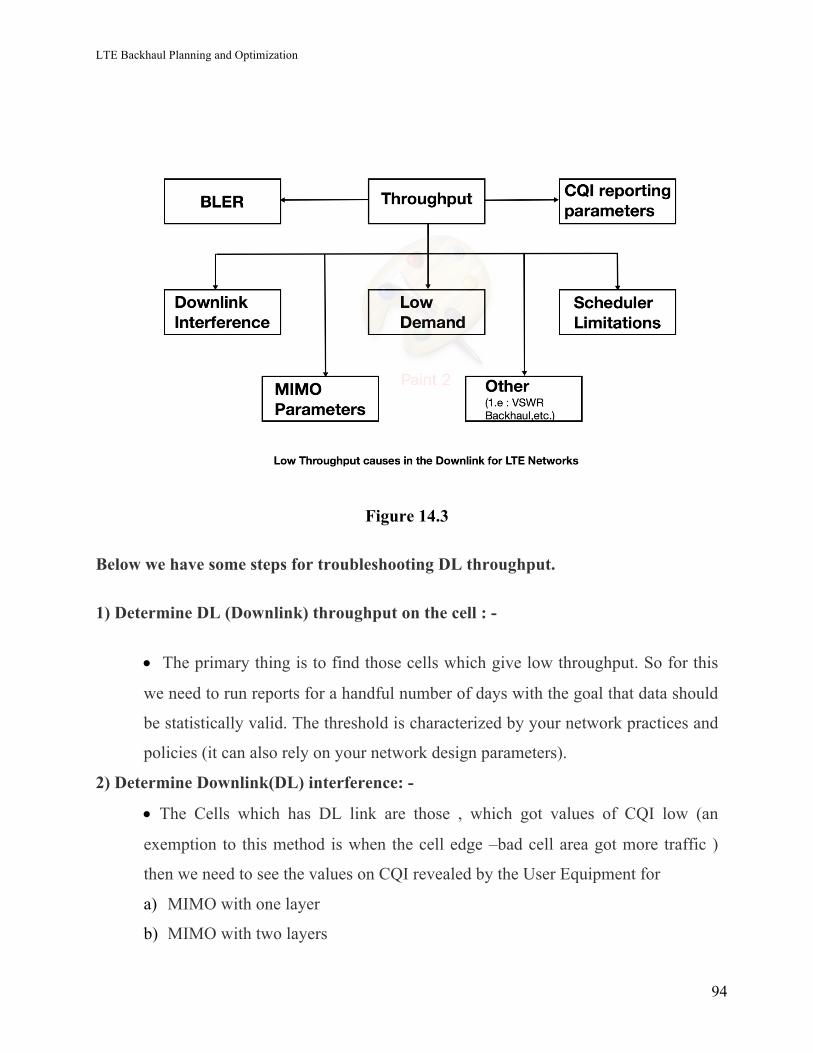
LTE Backhaul Planning and Optimization
94
Figure 14.3
Below we have some steps for troubleshooting DL throughput.
1) Determine DL (Downlink) throughput on the cell : -
• The primary thing is to find those cells which give low throughput. So for this
we need to run reports for a handful number of days with the goal that data should
be statistically valid. The threshold is characterized by your network practices and
policies (it can also rely on your network design parameters).
2) Determine Downlink(DL) interference: -
• The Cells which has DL link are those , which got values of CQI low (an
exemption to this method is when the cell edge –bad cell area got more traffic )
then we need to see the values on CQI revealed by the User Equipment for
a) MIMO with one layer
b) MIMO with two layers
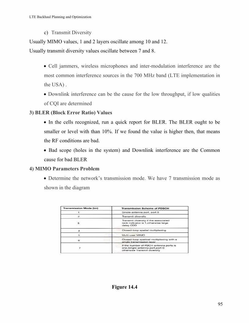
LTE Backhaul Planning and Optimization
95
c) Transmit Diversity
Usually MIMO values, 1 and 2 layers oscillate among 10 and 12.
Usually transmit diversity values oscillate between 7 and 8.
• Cell jammers, wireless microphones and inter-modulation interference are the
most common interference sources in the 700 MHz band (LTE implementation in
the USA) .
• Downlink interference can be the cause for the low throughput, if low qualities
of CQI are determined
3) BLER (Block Error Ratio) Values
• In the cells recognized, run a quick report for BLER. The BLER ought to be
smaller or level with than 10%. If we found the value is higher then, that means
the RF conditions are bad.
• Bad scope (holes in the system) and Downlink interference are the Common
cause for bad BLER
4) MIMO Parameters Problem
• Determine the network’s transmission mode. We have 7 transmission mode as
shown in the diagram
Figure 14.4
LTE Backhaul Planning and Optimization
96
• We can adjust the thresholds of SINR for transmission mode’s transitions as
prescribed by the OEM. Get the Link Level simulations which organization is
used to fix these thresholds. If the parameters are not limited and settable the
refresh them.
5) Low Demand
a) By using the counters given by the OEM to determine, run a report.
• Maximum count of RRC connections active/cell
• Maximum count of RRC connections supported by/cell (feature or parameter)
• Maximum count of users per TTI handled per cell (feature or parameter)
• Average count of RRC connections active/cell in the network
• Average count clients scheduled per TTI in the cell of interest
• Maximum count of clients scheduled per TTI in the cell of interest
b) The load is the reason for low throughput, If the most number of RRC
connections active/cell is close or equivalent to the greatest number of RRC
connections upheld.
c) A huge number of planned clients/TTI does not really imply that demand is the
reason for low throughput.
6) Scheduler Type in DL Throughput
• In your OEM handler, Determine the scheduler types.
• Which is more convenient , select that one for the kind of cell we are
investigating. Cases of schedulers are: proportional fairness round robin, greatest
C/I, equal opportunity, and so on. OEMs permit to switch the scheduler in your
system yet suggest one specifically.
• Sometime the wrong scheduler can be the cause behind bad throughput.
LTE Backhaul Planning and Optimization
97
7) Reporting parameters of CQI
• In which the CQI reporting has been done out for periodic
reporting , check the frequency and in addition the maximum client’s number
handled per second.
• Enable the CQI reporting, If the network is not using aperiodic.
• We need to verify the network, if it is utilizing periodic or aperiodic CQI
reporting.
• When the value is too little as compared with the maximum of RRC
active links count, then, increment the parameters CQIConfigIndex value and
RIConfigIndex too.
• Moderate frequencies of CQI reporting may yield bad channel bandwidths
estimations that keep away the eNodeB from scheduling the appropriate measure
of data and Mobile coding Schemes and Modulation.
8) Other Issues
• Check a VSWR report.
• If VSWR value is high then we find low throughput due to losses.
• Verify backhaul capacity. Mostly, the backhaul connections are shared between
multiple RATs. Be sure if your backhaul is accurately dimensioned for the
network.
At the end of this, We will be capable of finding out if the cause of the low throughput in
the cells is one of the below or a combination: -
At the end of this whole procedure, you will be able to figure out whether the causes
behind low throughput in the cells is one of the following : -
• Low Demand
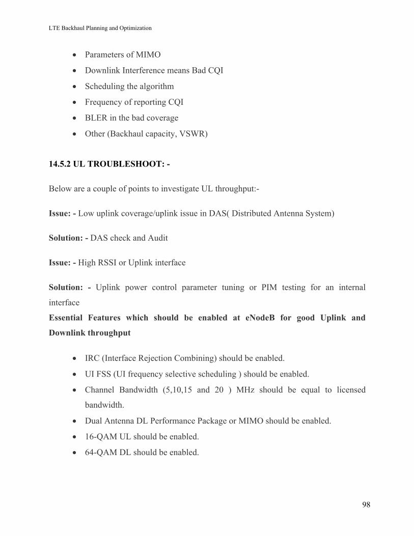
LTE Backhaul Planning and Optimization
98
• Parameters of MIMO
• Downlink Interference means Bad CQI
• Scheduling the algorithm
• Frequency of reporting CQI
• BLER in the bad coverage
• Other (Backhaul capacity, VSWR)
14.5.2 UL TROUBLESHOOT: -
Below are a couple of points to investigate UL throughput:-
Issue: - Low uplink coverage/uplink issue in DAS( Distributed Antenna System)
Solution: - DAS check and Audit
Issue: - High RSSI or Uplink interface
Solution: - Uplink power control parameter tuning or PIM testing for an internal
interface
Essential Features which should be enabled at eNodeB for good Uplink and
Downlink throughput
• IRC (Interface Rejection Combining) should be enabled.
• UI FSS (UI frequency selective scheduling ) should be enabled.
• Channel Bandwidth (5,10,15 and 20 ) MHz should be equal to licensed
bandwidth.
• Dual Antenna DL Performance Package or MIMO should be enabled.
• 16-QAM UL should be enabled.
• 64-QAM DL should be enabled.
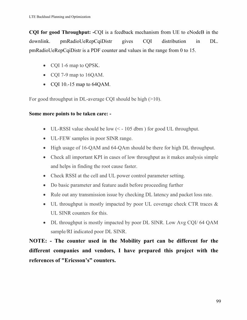
LTE Backhaul Planning and Optimization
99
CQI for good Throughput: -CQI is a feedback mechanism from UE to eNodeB in the
downlink. pmRadioUeRepCqiDistr gives CQI distribution in DL.
pmRadioUeRepCqiDistr is a PDF counter and values in the range from 0 to 15.
• CQI 1-6 map to QPSK.
• CQI 7-9 map to 16QAM.
• CQI 10.-15 map to 64QAM.
For good throughput in DL-average CQI should be high (>10).
Some more points to be taken care: -
• UL-RSSI value should be low (< - 105 dbm ) for good UL throughput.
• UL-FEW samples in poor SINR range.
• High usage of 16-QAM and 64-QAm should be there for high DL throughput.
• Check all important KPI in cases of low throughput as it makes analysis simple
and helps in finding the root cause faster.
• Check RSSI at the cell and UL power control parameter setting.
• Do basic parameter and feature audit before proceeding further
• Rule out any transmission issue by checking DL latency and packet loss rate.
• UL throughput is mostly impacted by poor UL coverage check CTR traces &
UL SINR counters for this.
• DL throughput is mostly impacted by poor DL SINR. Low Avg CQI/ 64 QAM
sample/RI indicated poor DL SINR.
NOTE: - The counter used in the Mobility part can be different for the
different companies and vendors, I have prepared this project with the
references of "Ericsson’s” counters.
LTE Backhaul Planning and Optimization
100
References: -
[1] https://www.scribd.com/doc/6995856/TEMS-Optimization-and-Log-File-Analysis-in-
GSM
[2] http://www.eventhelix.com/lte/attach/lte-attach.pdf
[3] http://lte-bullets.com/LTE%20in%20Bullets%20-%20RRC%20Establishment.pdf
[4]https://www.scribd.com/document/337389146/LTE-Network-Performance-Analysis-
For-DT-Exercise
[5] http://www.academia.edu/26369609/LTE_Post_launch_Optimization_-_V
[6]http://lteuniversity.com/get_trained/expert_opinion1/b/lauroortigoza/archive/2012/05/
17/uplink-throughput-troubleshooting.aspx
[7] https://www.scribd.com/document/210233684/LTE
[8] https://id.scribd.com/document/225980925/Fulani-uta-2502M-11046
[9]http://lteuniversity.com/get_trained/expert_opinion1/b/lauroortigoza/archive/2012/05/
09/downlink-throughput-troubleshooting.aspx
[10]https://www.scribd.com/presentation/239780601/Basic-3G-Performance-and-
Statistic-Analysis
[11] http://www.eventhelix.com/lte/handover/x2/lte-x2-handover-sequence-diagram.pdf
[12] https://www.scribd.com/document/333785290/3G-Retainability-Troubleshooting
[13] http://documents.tips/documents/1-lte-basic.html
[14] https://en.wikipedia.org/wiki/Handover
[15] http://kumarmohit.com/2013/01/handovers-in-lte/
[16] http://documents.tips/documents/essentials-of-lte-and-lte-a.html
[17]http://www.telecomsource.net/showthread.php?9191-LTE-DL-Throughput-
Optimization
LTE Backhaul Planning and Optimization
101
15. Conclusion In this project, we did research and study based on LTE Backhaul documents and books
presented on the internet. The architecture of LTE was explained. Each and every
parameter was explained which is useful to design the LTE backhaul network or to plan
LTE backhaul.
We explained topology as well which we used in the network design. With Hypothetical
thinking, An LTE based network was deployed in the city of Edmonton. As an
assumption, we implemented the network for the population of 30000 in the city. eNodeB
were count according to the population. By putting mix topology and different kind of
transmission media, LTE network is designed in the city of Edmonton. As all calculations
were supposed, so flaws in the network can be seen but they can be eradicated by doing
network optimization as shown in the final part.
In the last part of the project, Optimization has been mentioned. In the body of the last
segment, the three kinds of KPI is discussed. By using methods explained in the project,
the drawbacks in the network can be removed and system performance can be enhanced.
As the network is prepared only for 30000 population, so in future the population can be
increased and by regularly optimizing the network, it can be found that where is the
network coverage is bad or capacity need to be added and action can be taken
accordingly.
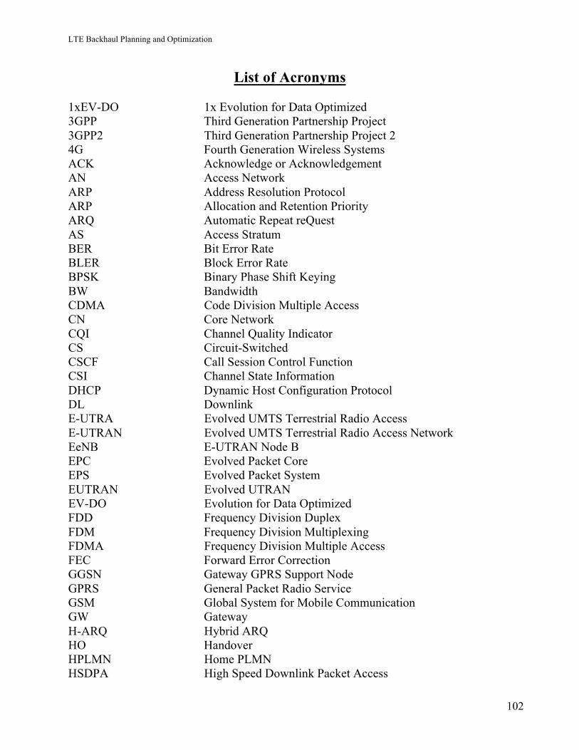
LTE Backhaul Planning and Optimization
102
List of Acronyms 1xEV-DO 1x Evolution for Data Optimized 3GPP Third Generation Partnership Project 3GPP2 Third Generation Partnership Project 2 4G Fourth Generation Wireless Systems ACK Acknowledge or Acknowledgement AN Access Network ARP Address Resolution Protocol ARP Allocation and Retention Priority ARQ Automatic Repeat reQuest AS Access Stratum BER Bit Error Rate BLER Block Error Rate BPSK Binary Phase Shift Keying BW Bandwidth CDMA Code Division Multiple Access CN Core Network CQI Channel Quality Indicator CS Circuit-Switched CSCF Call Session Control Function CSI Channel State Information DHCP Dynamic Host Configuration Protocol DL Downlink E-UTRA Evolved UMTS Terrestrial Radio Access E-UTRAN Evolved UMTS Terrestrial Radio Access Network EeNB E-UTRAN Node B EPC Evolved Packet Core EPS Evolved Packet System EUTRAN Evolved UTRAN EV-DO Evolution for Data Optimized FDD Frequency Division Duplex FDM Frequency Division Multiplexing FDMA Frequency Division Multiple Access FEC Forward Error Correction GGSN Gateway GPRS Support Node GPRS General Packet Radio Service GSM Global System for Mobile Communication GW Gateway H-ARQ Hybrid ARQ HO Handover HPLMN Home PLMN HSDPA High Speed Downlink Packet Access
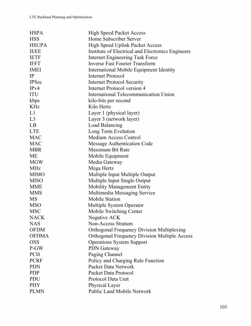
LTE Backhaul Planning and Optimization
103
HSPA High Speed Packet Access HSS Home Subscriber Server HSUPA High Speed Uplink Packet Access IEEE Institute of Electrical and Electronics Engineers IETF Internet Engineering Task Force IFFT Inverse Fast Fourier Transform IMEI International Mobile Equipment Identity IP Internet Protocol IPSec Internet Protocol Security IPv4 Internet Protocol version 4 ITU International Telecommunication Union kbps kilo-bits per second KHz Kilo Hertz L1 Layer 1 (physical layer) L3 Layer 3 (network layer) LB Load Balancing LTE Long Term Evolution MAC Medium Access Control MAC Message Authentication Code MBR Maximum Bit Rate ME Mobile Equipment MGW Media Gateway MHz Mega Hertz MIMO Multiple Input Multiple Output MISO Multiple Input Single Output MME Mobility Management Entity MMS Multimedia Messaging Service MS Mobile Station MSO Multiple System Operator MSC Mobile Switching Center NACK Negative ACK NAS Non-Access Stratum OFDM Orthogonal Frequency Division Multiplexing OFDMA Orthogonal Frequency Division Multiple Access OSS Operations System Support P-GW PDN Gateway PCH Paging Channel PCRF Policy and Charging Rule Function PDN Packet Data Network PDP Packet Data Protocol PDU Protocol Data Unit PHY Physical Layer PLMN Public Land Mobile Network
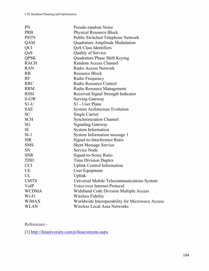
LTE Backhaul Planning and Optimization
104
PN Pseudo-random Noise PRB Physical Resource Block PSTN Public Switched Telephone Network QAM Quadrature Amplitude Modulation QCI QoS Class Identifiers QoS Quality of Service QPSK Quadrature Phase Shift Keying RACH Random Access Channel RAN Radio Access Network RB Resource Block RF Radio Frequency RRC Radio Resource Control RRM Radio Resource Management RSSI Received Signal Strength Indicator S-GW Serving Gateway S1-U S1 - User Plane SAE System Architecture Evolution SC Single Carrier SCH Synchronization Channel SG Signaling Gateway SI System Information SI-1 System Information message 1 SIR Signal-to-Interference Ratio SMS Short Message Service SN Service Node SNR Signal-to-Noise Ratio TDD Time Division Duplex UCI Uplink Control Information UE User Equipment UL Uplink UMTS Universal Mobile Telecommunications System VoIP Voice over Internet Protocol WCDMA Wideband Code Division Multiple Access Wi-Fi Wireless Fidelity WiMAX Worldwide Interoperability for Microwave Access WLAN Wireless Local Area Networks
Refrencees:-
[1] http://lteuniversity.com/p/lteacronyms.aspx