Embed Size (px)
Citation preview
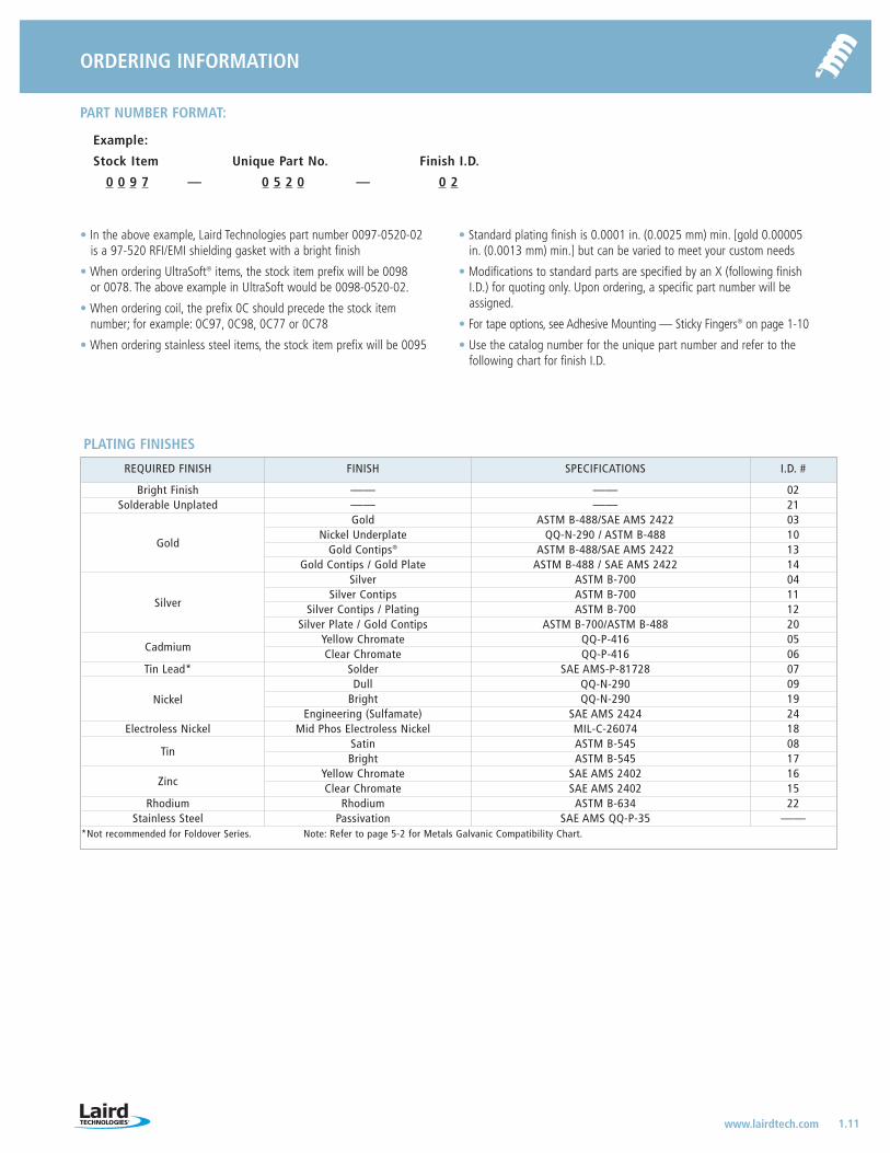
ORDERING INFORMATION
1.11www.lairdtech.com
PART NUMBER FORMAT:
Example:
Stock Item Unique Part No. Finish I.D.
0 0 9 7 — 0 5 2 0 — 0 2
• In the above example, Laird Technologies part number 0097-0520-02is a 97-520 RFI/EMI shielding gasket with a bright finish
• When ordering UltraSoft® items, the stock item prefix will be 0098 or 0078. The above example in UltraSoft would be 0098-0520-02.
• When ordering coil, the prefix 0C should precede the stock item number; for example: 0C97, 0C98, 0C77 or 0C78
• When ordering stainless steel items, the stock item prefix will be 0095
• Standard plating finish is 0.0001 in. (0.0025 mm) min. [gold 0.00005in. (0.0013 mm) min.] but can be varied to meet your custom needs
• Modifications to standard parts are specified by an X (following finishI.D.) for quoting only. Upon ordering, a specific part number will beassigned.
• For tape options, see Adhesive Mounting — Sticky Fingers® on page 1-10
• Use the catalog number for the unique part number and refer to thefollowing chart for finish I.D.
REQUIRED FINISH FINISH SPECIFICATIONS I.D. #
Bright Finish —— —— 02Solderable Unplated —— —— 21
Gold
Gold ASTM B-488/SAE AMS 2422 03Nickel Underplate QQ-N-290 / ASTM B-488 10
Gold Contips® ASTM B-488/SAE AMS 2422 13Gold Contips / Gold Plate ASTM B-488 / SAE AMS 2422 14
Silver
Silver ASTM B-700 04Silver Contips ASTM B-700 11
Silver Contips / Plating ASTM B-700 12Silver Plate / Gold Contips ASTM B-700/ASTM B-488 20
CadmiumYellow Chromate QQ-P-416 05Clear Chromate QQ-P-416 06
Tin Lead* Solder SAE AMS-P-81728 07
NickelDull QQ-N-290 09
Bright QQ-N-290 19Engineering (Sulfamate) SAE AMS 2424 24
Electroless Nickel Mid Phos Electroless Nickel MIL-C-26074 18
TinSatin ASTM B-545 08Bright ASTM B-545 17
ZincYellow Chromate SAE AMS 2402 16Clear Chromate SAE AMS 2402 15
Rhodium Rhodium ASTM B-634 22Stainless Steel Passivation SAE AMS QQ-P-35 ——
*Not recommended for Foldover Series. Note: Refer to page 5-2 for Metals Galvanic Compatibility Chart.
PLATING FINISHES
LT-3034 Metals_catalog 10/8/04 10:30 AM Page 1.11
FINGERSTOCK GASKETS AND METAL GROUNDING PRODUCTS
SLOT MOUNT SERIES
2.1 www.lairdtech.com
TOP VIEW
D Pitch
E
Slot
A
RIGHT VIEW
B
H
C
Q Radius (R)
M
Approx. Length
See page 2-2for dimensions.
See page 2-2for dimensions.
See page 2-2for dimensions.
77-015
77-018 77-010
77-011
*N
*O
Recommended Mounting Hole Pattern
*PMaterial
Thickness
Length of slot is dependent onthe number of fingers used
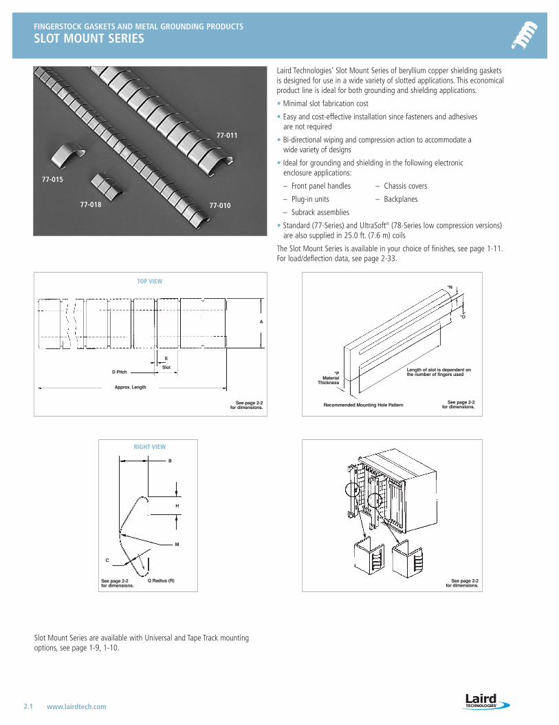
Laird Technologies’ Slot Mount Series of beryllium copper shielding gaskets is designed for use in a wide variety of slotted applications. This economicalproduct line is ideal for both grounding and shielding applications.
• Minimal slot fabrication cost
• Easy and cost-effective installation since fasteners and adhesivesare not required
• Bi-directional wiping and compression action to accommodate a wide variety of designs
• Ideal for grounding and shielding in the following electronic enclosure applications:
– Front panel handles – Chassis covers
– Plug-in units – Backplanes
– Subrack assemblies
• Standard (77-Series) and UltraSoft® (78-Series low compression versions)are also supplied in 25.0 ft. (7.6 m) coils
The Slot Mount Series is available in your choice of finishes, see page 1-11.For load/deflection data, see page 2-33.
See page 2-2for dimensions.
Slot Mount Series are available with Universal and Tape Track mountingoptions, see page 1-9, 1-10.
LT-3034 Metals_catalog 10/8/04 10:30 AM Page 2.1
FINGERSTOCK GASKETS AND METAL GROUNDING PRODUCTS
SLOT MOUNT SERIES
2.2www.lairdtech.com
All dimensions shown are in inches (millimeters) unless otherwise specified.
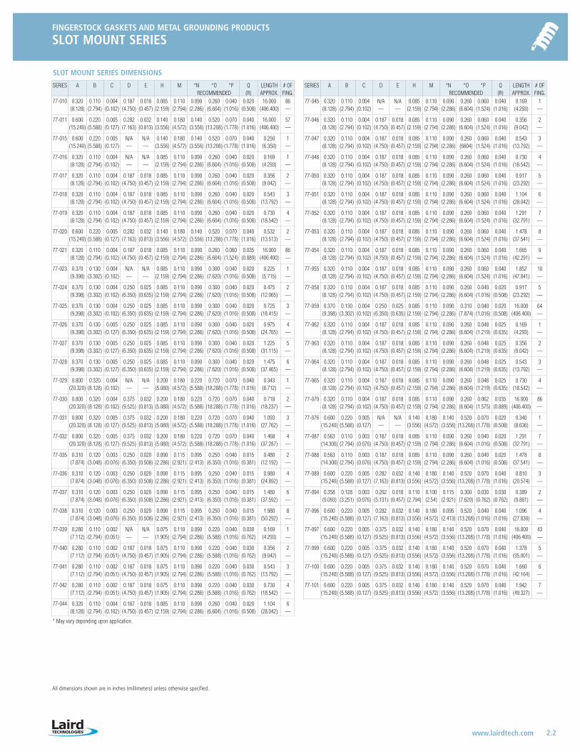
SERIES A B C D E H M *N *O *P Q LENGTH # OFRECOMMENDED (R) APPROX. FING.
77-045 0.320 0.110 0.004 N/A N/A 0.085 0.110 0.090 0.260 0.060 0.040 0.169 1(8.128) (2.794) (0.102) — — (2.159) (2.794) (2.286) (6.604) (1.524) (1.016) (4.293) —
77-046 0.320 0.110 0.004 0.187 0.018 0.085 0.110 0.090 0.260 0.060 0.040 0.356 2(8.128) (2.794) (0.102) (4.750) (0.457) (2.159) (2.794) (2.286) (6.604) (1.524) (1.016) (9.042) —
77-047 0.320 0.110 0.004 0.187 0.018 0.085 0.110 0.090 0.260 0.060 0.040 0.543 3(8.128) (2.794) (0.102) (4.750) (0.457) (2.159) (2.794) (2.286) (6604) (1.524) (1.016) (13.792) —
77-048 0.320 0.110 0.004 0.187 0.018 0.085 0.110 0.090 0.260 0.060 0.040 0.730 4(8.128) (2.794) (0.102) (4.750) (0.457) (2.159) (2.794) (2.286) (6.604) (1.524) (1.016) (18.542) —
77-050 0.320 0.110 0.004 0.187 0.018 0.085 0.110 0.090 0.260 0.060 0.040 0.917 5(8.128) (2.794) (0.102) (4.750) (0.457) (2.159) (2.794) (2.286) (6.604) (1.524) (1.016) (23.292) —
77-051 0.320 0.110 0.004 0.187 0.018 0.085 0.110 0.090 0.260 0.060 0.040 1.104 6(8.128) (2.794) (0.102) (4.750) (0.457) (2.159) (2.794) (2.286) (6.604) (1.524) (1.016) (28.042) —
77-052 0.320 0.110 0.004 0.187 0.018 0.085 0.110 0.090 0.260 0.060 0.040 1.291 7(8.128) (2.794) (0.102) (4.750) (0.457) (2.159) (2.794) (2.286) (6.604) (1.524) (1.016) (32.791) —
77-053 0.320 0.110 0.004 0.187 0.018 0.085 0.110 0.090 0.260 0.060 0.040 1.478 8(8.128) (2.794) (0.102) (4.750) (0.457) (2.159) (2.794) (2.286) (6.604) (1.524) (1.016) (37.541) —
77-054 0.320 0.110 0.004 0.187 0.018 0.085 0.110 0.090 0.260 0.060 0.040 1.665 9(8.128) (2.794) (0.102) (4.750) (0.457) (2.159) (2.794) (2.286) (6.604) (1.524) (1.016) (42.291) —
77-055 0.320 0.110 0.004 0.187 0.018 0.085 0.110 0.090 0.260 0.060 0.040 1.852 10(8.128) (2.794) (0.102) (4.750) (0.457) (2.159) (2.794) (2.286) (6.604) (1.524) (1.016) (47.041) —
77-058 0.320 0.110 0.004 0.187 0.018 0.085 0.110 0.090 0.260 0.040 0.020 0.917 5(8.128) (2.794) (0.102) (4.750) (0.457) (2.159) (2.794) (2.286) (6.604) (1.016) (0.508) (23.292) —
77-059 0.370 0.130 0.004 0.250 0.025 0.085 0.110 0.090 0.310 0.040 0.020 16.000 64(9.398) (3.302) (0.102) (6.350) (0.635) (2.159) (2.794) (2.286) (7.874) (1.016) (0.508) (406.400) —
77-062 0.320 0.110 0.004 0.187 0.018 0.085 0.110 0.090 0.260 0.048 0.025 0.169 1(8.128) (2.794) (0.102) (4.750) (0.457) (2.159) (2.794) (2.286) (6.604) (1.219) (0.635) (4.293) —
77-063 0.320 0.110 0.004 0.187 0.018 0.085 0.110 0.090 0.260 0.048 0.025 0.356 2(8.128) (2.794) (0.102) (4.750) (0.457) (2.159) (2.794) (2.286) (6.604) (1.219) (0.635) (9.042) —
77-064 0.320 0.110 0.004 0.187 0.018 0.085 0.110 0.090 0.260 0.048 0.025 0.543 3(8.128) (2.794) (0.102) (4.750) (0.457) (2.159) (2.794) (2.286) (6.604) (1.219) (0.635) (13.792) —
77-065 0.320 0.110 0.004 0.187 0.018 0.085 0.110 0.090 0.260 0.048 0.025 0.730 4(8.128) (2.794) (0.102) (4.750) (0.457) (2.159) (2.794) (2.286) (6.604) (1.219) (0.635) (18.542) —
77-070 0.320 0.110 0.004 0.187 0.018 0.085 0.110 0.090 0.260 0.062 0.035 16.000 86(8.128) (2.794) (0.102) (4.750) (0.457) (2.159) (2.794) (2.286) (6.604) (1.575) (0.889) (406.400) —
77-076 0.600 0.220 0.005 N/A N/A 0.140 0.180 0.140 0.520 0.070 0.020 0.340 1(15.240) (5.588) (0.127) — — (3.556) (4.572) (3.556) (13.208) (1.778) (0.508) (8.636) —
77-087 0.563 0.110 0.003 0.187 0.018 0.085 0.110 0.090 0.260 0.040 0.020 1.291 7(14.300) (2.794) (0.076) (4.750) (0.457) (2.159) (2.794) (2.286) (6.604) (1.016) (0.508) (32.791) —
77-088 0.563 0.110 0.003 0.187 0.018 0.085 0.110 0.090 0.260 0.040 0.020 1.478 8(14.300) (2.794) (0.076) (4.750) (0.457) (2.159) (2.794) (2.286) (6.604) (1.016) (0.508) (37.541) —
77-089 0.600 0.220 0.005 0.282 0.032 0.140 0.180 0.140 0.520 0.070 0.040 0.810 3(15.240) (5.588) (0.127) (7.163) (0.813) (3.556) (4.572) (3.556) (13.208) (1.778) (1.016) (20.574) —
77-094 0.358 0.128 0.003 0.202 0.018 0.110 0.100 0.115 0.300 0.030 0.030 0.389 2(9.093) (3.251) (0.076) (5.131) (0.457) (2.794) (2.54) (2.921) (7.620) (0.762) (0.762) (9.881) —
77-096 0.600 0.220 0.005 0.282 0.032 0.140 0.180 0.095 0.520 0.040 0.040 1.096 4(15.240) (5.588) (0.127) (7.163) (0.813) (3.556) (4.572) (2.413) (13.208) (1.016) (1.016) (27.838) —
77-097 0.600 0.220 0.005 0.375 0.032 0.140 0.180 0.140 0.520 0.070 0.040 16.000 43(15.240) (5.588) (0.127) (9.525) (0.813) (3.556) (4.572) (3.556) (13.208) (1.778) (1.016) (406.400) —
77-099 0.600 0.220 0.005 0.375 0.032 0.140 0.180 0.140 0.520 0.070 0.040 1.378 5(15.240) (5.588) (0.127) (9.525) (0.813) (3.556) (4.572) (3.556) (13.208) (1.778) (1.016) (35.001) —
77-100 0.600 0.220 0.005 0.375 0.032 0.140 0.180 0.140 0.520 0.070 0.040 1.660 6(15.240) (5.588) (0.127) (9.525) (0.813) (3.556) (4.572) (3.556) (13.208) (1.778) (1.016) (42.164) —
77-101 0.600 0.220 0.005 0.375 0.032 0.140 0.180 0.140 0.520 0.070 0.040 1.942 7(15.240) (5.588) (0.127) (9.525) (0.813) (3.556) (4.572) (3.556) (13.208) (1.778) (1.016) (49.327) —
SERIES A B C D E H M *N *O *P Q LENGTH # OFRECOMMENDED (R) APPROX. FING.
77-010 0.320 0.110 0.004 0.187 0.018 0.085 0.110 0.090 0.260 0.040 0.020 16.000 86(8.128) (2.794) (0.102) (4.750) (0.457) (2.159) (2.794) (2.286) (6.604) (1.016) (0.508) (406.400) —
77-011 0.600 0.220 0.005 0.282 0.032 0.140 0.180 0.140 0.520 0.070 0.040 16.000 57(15.240) (5.588) (0.127) (7.163) (0.813) (3.556) (4.572) (3.556) (13.208) (1.778) (1.016) (406.400) —
77-015 0.600 0.220 0.005 N/A N/A 0.140 0.180 0.140 0.520 0.070 0.040 0.250 1(15.240) (5.588) (0.127) — — (3.556) (4.572) (3.556) (13.208) (1.778) (1.016) (6.350) —
77-016 0.320 0.110 0.004 N/A N/A 0.085 0.110 0.090 0.260 0.040 0.020 0.169 1(8.128) (2.794) (0.102) — — (2.159) (2.794) (2.286) (6.604) (1.016) (0.508) (4.293) —
77-017 0.320 0.110 0.004 0.187 0.018 0.085 0.110 0.090 0.260 0.040 0.020 0.356 2(8.128) (2.794) (0.102) (4.750) (0.457) (2.159) (2.794) (2.286) (6.604) (1.016) (0.508) (9.042) —
77-018 0.320 0.110 0.004 0.187 0.018 0.085 0.110 0.090 0.260 0.040 0.020 0.543 3(8.128) (2.794) (0.102) (4.750) (0.457) (2.159) (2.794) (2.286) (6.604) (1.016) (0.508) (13.792) —
77-019 0.320 0.110 0.004 0.187 0.018 0.085 0.110 0.090 0.260 0.040 0.020 0.730 4(8.128) (2.794) (0.102) (4.750) (0.457) (2.159) (2.794) (2.286) (6.604) (1.016) (0.508) (18.542) —
77-020 0.600 0.220 0.005 0.282 0.032 0.140 0.180 0.140 0.520 0.070 0.040 0.532 2(15.240) (5.588) (0.127) (7.163) (0.813) (3.556) (4.572) (3.556) (13.208) (1.778) (1.016) (13.513) —
77-021 0.320 0.110 0.004 0.187 0.018 0.085 0.110 0.090 0.260 0.060 0.035 16.000 86(8.128) (2.794) (0.102) (4.750) (0.457) (2.159) (2.794) (2.286) (6.604) (1.524) (0.889) (406.400) —
77-023 0.370 0.130 0.004 N/A N/A 0.085 0.110 0.090 0.300 0.040 0.020 0.225 1(9.398) (3.302) (0.102) — — (2.159) (2.794) (2.286) (7.620) (1.016) (0.508) (5.715) —
77-024 0.370 0.130 0.004 0.250 0.025 0.085 0.110 0.090 0.300 0.040 0.020 0.475 2(9.398) (3.302) (0.102) (6.350) (0.635) (2.159) (2.794) (2.286) (7.620) (1.016) (0.508) (12.065) —
77-025 0.370 0.130 0.004 0.250 0.025 0.085 0.110 0.090 0.300 0.040 0.020 0.725 3(9.398) (3.302) (0.102) (6.350) (0.635) (2.159) (2.794) (2.286) (7.620) (1.016) (0.508) (18.415) —
77-026 0.370 0.130 0.005 0.250 0.025 0.085 0.110 0.090 0.300 0.040 0.020 0.975 4(9.398) (3.302) (0.127) (6.350) (0.635) (2.159) (2.794) (2.286) (7.620) (1.016) (0.508) (24.765) —
77-027 0.370 0.130 0.005 0.250 0.025 0.085 0.110 0.090 0.300 0.040 0.020 1.225 5(9.398) (3.302) (0.127) (6.350) (0.635) (2.159) (2.794) (2.286) (7.620) (1.016) (0.508) (31.115) —
77-028 0.370 0.130 0.005 0.250 0.025 0.085 0.110 0.090 0.300 0.040 0.020 1.475 6(9.398) (3.302) (0.127) (6.350) (0.635) (2.159) (2.794) (2.286) (7.620) (1.016) (0.508) (37.465) —
77-029 0.800 0.320 0.004 N/A N/A 0.200 0.180 0.220 0.720 0.070 0.040 0.343 1(20.320) (8.128) (0.102) — — (5.080) (4.572) (5.588) (18.288) (1.778) (1.016) (8.712) —
77-030 0.800 0.320 0.004 0.375 0.032 0.200 0.180 0.220 0.720 0.070 0.040 0.718 2(20.320) (8.128) (0.102) (9.525) (0.813) (5.080) (4.572) (5.588) (18.288) (1.778) (1.016) (18.237) —
77-031 0.800 0.320 0.005 0.375 0.032 0.200 0.180 0.220 0.720 0.070 0.040 1.093 3(20.320) (8.128) (0.127) (9.525) (0.813) (5.080) (4.572) (5.588) (18.288) (1.778) (1.016) (27.762) —
77-032 0.800 0.320 0.005 0.375 0.032 0.200 0.180 0.220 0.720 0.070 0.040 1.468 4(20.320) (8.128) (0.127) (9.525) (0.813) (5.080) (4.572) (5.588) (18.288) (1.778) (1.016) (37.287) —
77-035 0.310 0.120 0.003 0.250 0.020 0.090 0.115 0.095 0.250 0.040 0.015 0.480 2(7.874) (3.048) (0.076) (6.350) (0.508) (2.286) (2.921) (2.413) (6.350) (1.016) (0.381) (12.192) —
77-036 0.310 0.120 0.003 0.250 0.020 0.090 0.115 0.095 0.250 0.040 0.015 0.980 4(7.874) (3.048) (0.076) (6.350) (0.508) (2.286) (2.921) (2.413) (6.350) (1.016) (0.381) (24.892) —
77-037 0.310 0.120 0.003 0.250 0.020 0.090 0.115 0.095 0.250 0.040 0.015 1.480 6(7.874) (3.048) (0.076) (6.350) (0.508) (2.286) (2.921) (2.413) (6.350) (1.016) (0.381) (37.592) —
77-038 0.310 0.120 0.003 0.250 0.020 0.090 0.115 0.095 0.250 0.040 0.015 1.980 8(7.874) (3.048) (0.076) (6.350) (0.508) (2.286) (2.921) (2.413) (6.350) (1.016) (0.381) (50.292) —
77-039 0.280 0.110 0.002 N/A N/A 0.075 0.110 0.090 0.220 0.040 0.030 0.169 1(7.112) (2.794) (0.051) — — (1.905) (2.794) (2.286) (5.588) (1.016) (0.762) (4.293) —
77-040 0.280 0.110 0.002 0.187 0.018 0.075 0.110 0.090 0.220 0.040 0.030 0.356 2(7.112) (2.794) (0.051) (4.750) (0.457) (1.905) (2.794) (2.286) (5.588) (1.016) (0.762) (9.042) —
77-041 0.280 0.110 0.002 0.187 0.018 0.075 0.110 0.090 0.220 0.040 0.030 0.543 3(7.112) (2.794) (0.051) (4.750) (0.457) (1.905) (2.794) (2.286) (5.588) (1.016) (0.762) (13.792) —
77-042 0.280 0.110 0.002 0.187 0.018 0.075 0.110 0.090 0.220 0.040 0.030 0.730 4(7.112) (2.794) (0.051) (4.750) (0.457) (1.905) (2.794) (2.286) (5.588) (1.016) (0.762) (18.542) —
77-044 0.320 0.110 0.004 0.187 0.018 0.085 0.110 0.090 0.260 0.040 0.020 1.104 6(8.128) (2.794) (0.102) (4.750) (0.457) (2.159) (2.794) (2.286) (6.604) (1.016) (0.508) (28.042) —
* May vary depending upon application.
SLOT MOUNT SERIES DIMENSIONS
LT-3034 Metals_catalog 10/8/04 10:30 AM Page 2.2
FINGERSTOCK GASKETS AND METAL GROUNDING PRODUCTS
DUAL SLOT SERIES
2.3 www.lairdtech.com
All dimensions shown are in inches (millimeters) unless otherwise specified.
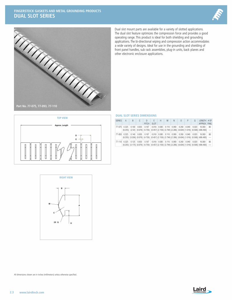
Dual slot mount parts are available for a variety of slotted applications.The dual slot feature optimizes the compression force and provides a goodoperating range. This product is ideal for both shielding and grounding applications. The bi-directional wiping and compression action accommodatesa wide variety of designs. Ideal for use in the grounding and shielding offront panel handles, sub rack assemblies, plug-in units, back planes andother electronic enclosure applications.
SERIES A B C D E H M N O P Q LENGTH # OFPITCH SLOT APPROX. FING.
77-075 0.325 0.100 0.003 0.187 0.018 0.085 0.110 0.090 0.260 0.040 0.020 16.000 86(8.255) (2.54) (0.076) (4.750) (0.457) (2.159) (2.794) (2.286) (6.604) (1.016) (0.508) (406.400) —
77-093 0.325 0.140 0.003 0.187 0.018 0.085 0.110 0.090 0.260 0.040 0.020 16.000 86(8.255) (3.556) (0.076) (4.750) (0.457) (2.159) (2.794) (2.286) (6.604) (1.016) (0.508) (406.400) —
77-110 0.325 0.125 0.003 0.187 0.018 0.085 0.110 0.090 0.260 0.040 0.020 16.000 86(8.255) (3.175) (0.076) (4.750) (0.457) (2.159) (2.794) (2.286) (6.604) (1.016) (0.508) (406.400) —
DUAL SLOT SERIES DIMENSIONSTOP VIEW
RIGHT VIEW
B
AM
C
H2X Q
Approx. Length
D
E
Part No. 77-075, 77-093, 77-110
LT-3034 Metals_catalog 10/8/04 10:30 AM Page 2.3
FINGERSTOCK GASKETS AND METAL GROUNDING PRODUCTS
COMPACT PCI SYMMETRICAL MOUNT
2.4www.lairdtech.com
FINGERSTOCK GASKETS AND METAL GROUNDING PRODUCTS
ALTERNATE SLOT SERIES
All dimensions shown are in inches (millimeters) unless otherwise specified.
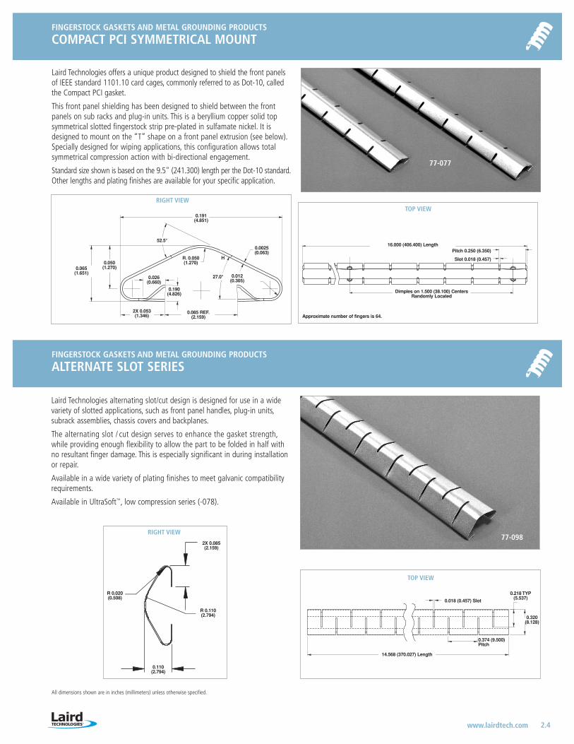
Laird Technologies alternating slot/cut design is designed for use in a widevariety of slotted applications, such as front panel handles, plug-in units,subrack assemblies, chassis covers and backplanes.
The alternating slot / cut design serves to enhance the gasket strength,while providing enough flexibility to allow the part to be folded in half withno resultant finger damage. This is especially significant in during installation or repair.
Available in a wide variety of plating finishes to meet galvanic compatibilityrequirements.
Available in UltraSoft™, low compression series (-078).
TOP VIEWRIGHT VIEW
0.191(4.851)
H0.050
(1.270)
R. 0.050(1.270)
52.5°
27.0°0.026(0.660)
2X 0.053 (1.346)
0.190(4.826)
0.0025(0.063)
0.012(0.305)
0.085 REF.(2.159)
0.065(1.651)
TOP VIEW
16.000 (406.400) Length
14.568 (370.027) Length
0.374 (9.500) Pitch
0.320(8.128)
0.218 TYP(5.537)0.018 (0.457) Slot
Dimples on 1.500 (38.100) CentersRandomly Located
Approximate number of fingers is 64.
Pitch 0.250 (6.350)
Slot 0.018 (0.457)
77-077
77-098
Laird Technologies offers a unique product designed to shield the front panelsof IEEE standard 1101.10 card cages, commonly referred to as Dot-10, calledthe Compact PCI gasket.
This front panel shielding has been designed to shield between the front panels on sub racks and plug-in units. This is a beryllium copper solid topsymmetrical slotted fingerstock strip pre-plated in sulfamate nickel. It isdesigned to mount on the “T” shape on a front panel extrusion (see below).Specially designed for wiping applications, this configuration allows total symmetrical compression action with bi-directional engagement.
Standard size shown is based on the 9.5" (241.300) length per the Dot-10 standard.Other lengths and plating finishes are available for your specific application.
RIGHT VIEW
2X 0.085(2.159)
R 0.110(2.794)
R 0.020(0.508)
0.110(2.794)
LT-3034 Metals_catalog 10/8/04 10:30 AM Page 2.4

FINGERSTOCK GASKETS AND METAL GROUNDING PRODUCTS
VARIABLE SLOT MOUNT
2.5 www.lairdtech.com
50
45
40
35
30
25
20
15
10
5
0
Lo
ad (
po
un
ds
per
lin
ear
foo
t)
70
60
50
40
30
20
10
0
Lo
ad (
kilo
gra
ms-
forc
e p
er li
nea
r m
eter
)
0 20 40 60 80
77-056
78-056
Compression/DeflectionPart No: 77-56-02 (Variable Slot Mount Series)
Deflection (%)
E Slot
D Pitch
A
FRONT VIEW
Approx. Length
B
M
QC
RIGHT VIEW FIGURE 2
Material Thickness
Length of slot and distancebetween slots is dependenton hole mounting pattern.*P
*N
*O
SERIES A B C D E H M *N *O *P Q LENGTH # OFVIEW** RECOMMENDED (R) APPROX. FING.77-090 0.600 0.220 0.005 0.282 0.032 0.140 0.180 0.140 0.520 0.070 0.040 16.000 57
B (15.240) (5.588) (0.127) (7.163) (0.813) (3.556) (4.572) (3.556) (13.208) (1.778) (1.016) (406.400) —
77-105 0.600 0.220 0.005 0.282 0.032 0.140 0.180 0.140 0.520 0.070 0.040 16.000 57C (15.240) (5.588) (0.127) (7.163) (0.813) ( 3.556) (4.572) (3.556) (13.208) (1.778) (1.016) (406.400) —
77-106 0.600 0.220 0.005 0.282 0.032 0.140 0.180 0.140 0.520 0.070 0.040 16.000 57D (15.240) (5.588) (0.127) (7.163) (0.813) ( 3.556) (4.572) (3.556) (13.208) (1.778) (1.016) (406.400) —
77-107 0.600 0.220 0.005 0.282 0.032 0.140 0.180 0.140 0.520 0.070 0.040 16.000 57E (15.240) (5.588) (0.127) (7.163) (0.813) ( 3.556) (4.572) (3.556) (13.208) (1.778) (1.016) (406.400) —
* May vary depending upon application.** See Figure 1 for finger patterns.
SERIES A B C D E H M *N *O *P Q LENGTH # OFVIEW** RECOMMENDED (R) APPROX. FING.77-056 0.320 0.110 0.004 0.187 0.018 0.085 0.110 0.090 0.260 0.040 0.020 16.000 86
A (8.128) (2.794) (0.102) (4.750) (0.457) (2.159) (2.794) (2.286) (6.604) (1.016) (0.508) (406.400) —
77-057 0.600 0.220 0.005 0.282 0.032 0.130 0.180 0.140 0.520 0.070 0.040 16.000 57A (15.240) (5.588) (0.127) (7.163) (0.813) (3.302) (4.572) (3.556) (13.208) (1.778) (1.016) (406.400) —
77-060 0.320 0.110 0.003 0.187 0.018 0.085 0.110 0.090 0.260 0.040 0.020 16.000 86E (8.128) (2.794) (0.076) (4.750) (0.457) (2.159) (2.794) (2.286) (6.604) (1.016) (0.508) (406.400) —
77-061 0.320 0.110 0.003 0.187 0.018 0.085 0.110 0.090 0.260 0.040 0.020 16.000 86B (8.128) (2.794) (0.076) (4.750) (0.457) (2.159) (2.794) (2.286) (6.604) (1.016) (0.508) (406.400) —
77-066 0.320 0.110 0.003 0.187 0.018 0.085 0.110 0.090 0.260 0.040 0.020 16.000 86C (8.128) (2.794) (0.076) (4.750) (0.457) (2.159) (2.794) (2.286) (6.604) (1.016) (0.508) (406.400) —
VARIABLE SLOT MOUNT DIMENSIONS
H
Laird Technologies introduces Variable Slot Mount shielding, which eliminatesthe use of long slots while still utilizing the easy installation method of slotmount shielding. Fingers are removed from the strip in areas where a mountingslot is not present. The Variable Slot Mount shielding strips can be customizedto any patterned series of slots.
• Easy and cost-effective installation since fasteners and adhesives are not required
• Improved shielding effectiveness compared to traditional slot mount seriesthrough elimination of long slots in host material
• Slot mounting feature can be varied to accommodate different lengths and hole mounting patterns (see figure 2)
• Three and five pitch segments ideal for grounding applications
• Bi-directional wiping and compression action to accommodate a wide variety of designs
• Available in standard (77-Series) and UltraSoft® (78-Series low compression versions)
• Ability to retrofit equipment when higher clock speeds limit current slotmount product without changing slot size or location
• One piece construction eliminates handling individual pieces, thereby shorteninginstallation time
• Ideal for grounding and shielding in the following electronic enclosure applications:
– Front panel handles – Chassis covers – Backplanes– Plug-in units – Subrack assemblies
Repeating Finger Pattern for 77-056 and 77-057A
Repeating Finger Pattern for 77-090 and 77-061B
Repeating Finger Pattern for 77-105, and 77-066C
Repeating Finger Pattern for 77-106D
Repeating Finger Pattern for 77-060 and 77-107E
FullFinger
SemiFinger
77-057
77-066
77-060
77-056
FIGURE 1: REPEATING FINGER PATTERN
LT-3034 Metals_catalog 10/8/04 10:30 AM Page 2.5
FINGERSTOCK GASKETS AND METAL GROUNDING PRODUCTS
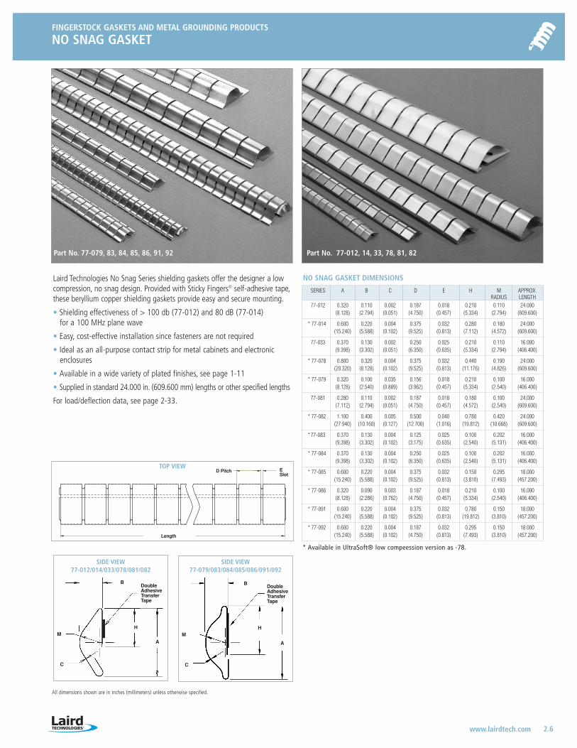
NO SNAG GASKET
2.6www.lairdtech.com
All dimensions shown are in inches (millimeters) unless otherwise specified.
TOP VIEW
Length
ESlot
D Pitch
Laird Technologies No Snag Series shielding gaskets offer the designer a lowcompression, no snag design. Provided with Sticky Fingers® self-adhesive tape,these beryllium copper shielding gaskets provide easy and secure mounting.
• Shielding effectiveness of > 100 db (77-012) and 80 dB (77-014) for a 100 MHz plane wave
• Easy, cost-effective installation since fasteners are not required
• Ideal as an all-purpose contact strip for metal cabinets and electronicenclosures
• Available in a wide variety of plated finishes, see page 1-11
• Supplied in standard 24.000 in. (609.600 mm) lengths or other specified lengths
For load/deflection data, see page 2-33.
SERIES A B C D E H M APPROX.RADIUS LENGTH
77-012 0.320 0.110 0.002 0.187 0.018 0.210 0.110 24.000(8.128) (2.794) (0.051) (4.750) (0.457) (5.334) (2.794) (609.600)
* 77-014 0.600 0.220 0.004 0.375 0.032 0.280 0.180 24.000(15.240) (5.588) (0.102) (9.525) (0.813) (7.112) (4.572) (609.600)
77-033 0.370 0.130 0.002 0.250 0.025 0.210 0.110 16.000(9.398) (3.302) (0.051) (6.350) (0.635) (5.334) (2.794) (406.400)
* 77-078 0.800 0.320 0.004 0.375 0.032 0.440 0.190 24.000(20.320) (8.128) (0.102) (9.525) (0.813) (11.176) (4.826) (609.600)
* 77-079 0.320 0.100 0.035 0.156 0.018 0.210 0.100 16.000(8.128) (2.540) (0.889) (3.962) (0.457) (5.334) (2.540) (406.400)
77-081 0.280 0.110 0.002 0.187 0.018 0.180 0.100 24.000(7.112) (2.794) (0.051) (4.750) (0.457) (4.572) (2.540) (609.600)
* 77-082 1.100 0.400 0.005 0.500 0.040 0.780 0.420 24.000(27.940) (10.160) (0.127) (12.700) (1.016) (19.812) (10.668) (609.600)
* 77-083 0.370 0.130 0.004 0.125 0.025 0.100 0.202 16.000(9.398) (3.302) (0.102) (3.175) (0.635) (2.540) (5.131) (406.400)
* 77-084 0.370 0.130 0.004 0.250 0.025 0.100 0.202 16.000(9.398) (3.302) (0.102) (6.350) (0.635) (2.540) (5.131) (406.400)
* 77-085 0.600 0.220 0.004 0.375 0.032 0.150 0.295 18.000(15.240) (5.588) (0.102) (9.525) (0.813) (3.810) (7.493) (457.200)
* 77-086 0.320 0.090 0.003 0.187 0.018 0.210 0.100 16.000(8.128) (2.286) (0.762) (4.750) (0.457) (5.334) (2.540) (406.400)
* 77-091 0.600 0.220 0.004 0.375 0.032 0.780 0.150 18.000(15.240) (5.588) (0.102) (9.525) (0.813) (19.812) (3.810) (457.200)
* 77-092 0.600 0.220 0.004 0.187 0.032 0.295 0.150 18.000(15.240) (5.588) (0.102) (4.750) (0.813) (7.493) (3.810) (457.200)
NO SNAG GASKET DIMENSIONS
SIDE VIEW77-012/014/033/078/081/082
BDoubleAdhesive Transfer Tape
A
HM
C
SIDE VIEW77-079/083/084/085/086/091/092
BDoubleAdhesive Transfer Tape
A
HM
C
Part No. 77-079, 83, 84, 85, 86, 91, 92 Part No. 77-012, 14, 33, 78, 81, 82
* Available in UltraSoft® low compeession version as -78.
LT-3034 Metals_catalog 10/8/04 10:30 AM Page 2.6
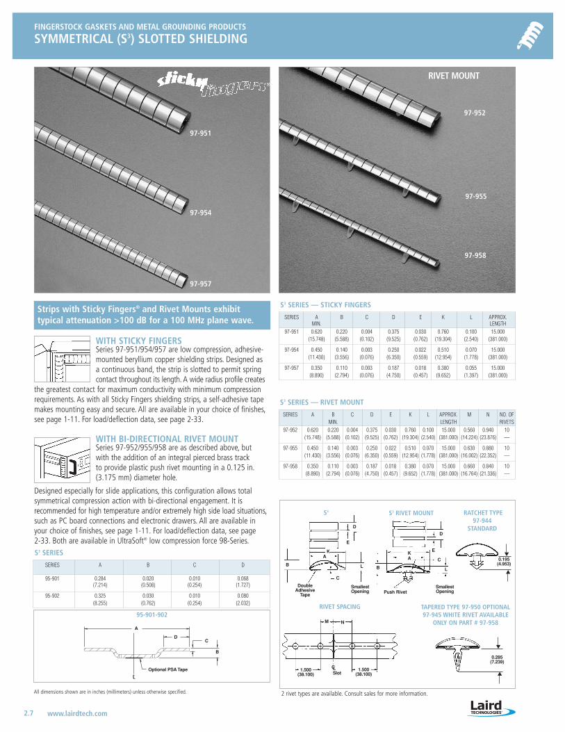
FINGERSTOCK GASKETS AND METAL GROUNDING PRODUCTS
SYMMETRICAL (S3) SLOTTED SHIELDING
2.7 www.lairdtech.com
All dimensions shown are in inches (millimeters) unless otherwise specified.
WITH STICKY FINGERSSeries 97-951/954/957 are low compression, adhesive-mounted beryllium copper shielding strips. Designed as a continuous band, the strip is slotted to permit springcontact throughout its length. A wide radius profile creates
the greatest contact for maximum conductivity with minimum compressionrequirements. As with all Sticky Fingers shielding strips, a self-adhesive tapemakes mounting easy and secure. All are available in your choice of finishes,see page 1-11. For load/deflection data, see page 2-33.
WITH BI-DIRECTIONAL RIVET MOUNTSeries 97-952/955/958 are as described above, but with the addition of an integral pierced brass track to provide plastic push rivet mounting in a 0.125 in.(3.175 mm) diameter hole.
Designed especially for slide applications, this configuration allows total symmetrical compression action with bi-directional engagement. It is recommended for high temperature and/or extremely high side load situations,such as PC board connections and electronic drawers. All are available inyour choice of finishes, see page 1-11. For load/deflection data, see page 2-33. Both are available in UltraSoft® low compression force 98-Series.
SmallestOpening
S3 S3 RIVET MOUNT
RIVET SPACING TAPERED TYPE 97-950 OPTIONAL 97-945 WHITE RIVET AVAILABLE
ONLY ON PART # 97-958
RATCHET TYPE97-944
STANDARD
RIVET MOUNT
97-952
97-955
97-958
97-951
97-954
97-957
Strips with Sticky Fingers® and Rivet Mounts exhibit typical attenuation >100 dB for a 100 MHz plane wave.
N
D
1.500(38.100)
C
CL Slot
M
E
A
B
0.285(7.239)
0.195(4.953)
1.500(38.100)
E
DoubleAdhesive
Tape
L
K
D
CKA
B L
Push RivetSmallestOpening
SERIES A B C D E K L APPROX. M N NO. OFMIN. LENGTH RIVETS
97-952 0.620 0.220 0.004 0.375 0.030 0.760 0.100 15.000 0.560 0.940 10(15.748) (5.588) (0.102) (9.525) (0.762) (19.304) (2.540) (381.000) (14.224) (23.876) —
97-955 0.450 0.140 0.003 0.250 0.022 0.510 0.070 15.000 0.630 0.880 10(11.430) (3.556) (0.076) (6.350) (0.559) (12.954) (1.778) (381.000) (16.002) (22.352) —
97-958 0.350 0.110 0.003 0.187 0.018 0.380 0.070 15.000 0.660 0.840 10(8.890) (2.794) (0.076) (4.750) (0.457) (9.652) (1.778) (381.000) (16.764) (21.336) —
S3 SERIES — RIVET MOUNT
SERIES A B C D E K L APPROX.MIN. LENGTH
97-951 0.620 0.220 0.004 0.375 0.030 0.760 0.100 15.000(15.748) (5.588) (0.102) (9.525) (0.762) (19.304) (2.540) (381.000)
97-954 0.450 0.140 0.003 0.250 0.022 0.510 0.070 15.000(11.430) (3.556) (0.076) (6.350) (0.559) (12.954) (1.778) (381.000)
97-957 0.350 0.110 0.003 0.187 0.018 0.380 0.055 15.000(8.890) (2.794) (0.076) (4.750) (0.457) (9.652) (1.397) (381.000)
S3 SERIES — STICKY FINGERS
SERIES A B C D
95-901 0.284 0.020 0.010 0.068(7.214) (0.508) (0.254) (1.727)
95-902 0.325 0.030 0.010 0.080(8.255) (0.762) (0.254) (2.032)
S3 SERIES
2 rivet types are available. Consult sales for more information.
95-901-902
A
DC
B
Optional PSA Tape
LT-3034 Metals_catalog 10/8/04 10:30 AM Page 2.7
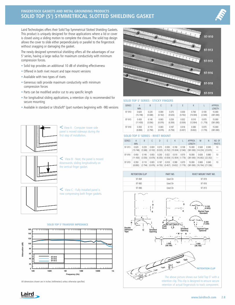
97-91997-91697-913
SOLID TOP S3 TRANSFER IMPEDANCE
10K 100K 1M 10M 100M 1G
Frequency (Hz)
Att
enua
tion
(dB
)
160
140
120
100
80
60
40
20
0
RETENTION CLIP PART NO. RIVET MOUNT PART NO.
97-964 Used On 97-919
97-965 Used On 97-916
97-966 Used On 97-913
FINGERSTOCK GASKETS AND METAL GROUNDING PRODUCTS
SOLID TOP (S3) SYMMETRICAL SLOTTED SHIELDING GASKET
2.8www.lairdtech.com
All dimensions shown are in inches (millimeters) unless otherwise specified.
SOLID TOP S3 SERIES - STICKY FINGERS
SOLID TOP S3 SERIES - RIVET MOUNT
Laird Technologies offers their Solid Top Symmetrical Slotted Shielding Gaskets.This product is uniquely designed for those applications where a lid or coveris closed using a sliding motion to complete the closure. The solid top designallows the cover to slide either perpendicularly or parallel to the fingerstockwithout snagging or damaging the gasket.
The newly designed symmetrical shielding offers all the advantages of our S3 series, having a large radius for maximum conductivity with minimumcompression forces.
• Solid top provides an additional 10 dB of shielding effectiveness
• Offered in both rivet mount and tape mount versions
• Available with two types of rivets
• Generous radii provide maximum conductivity with minimum compression forces
• Parts can be modified and/or cut to any specific length
• For longitudinal sliding applications, a retention clip is recommended forsecure mounting
• Available in standard or UltraSoft® (part numbers beginning with -98) versions
< View A - Computer tower sidepanel is moved sideways during thefirst step of installation.
< View B - Next, the panel is moveddownwards, sliding longitudinally onthe vertical finger gasket.
< View C - Fully installed panel isnow compressing both finger gaskets.
The above picture shows our Solid Top S3 with aretention clip. This clip is designed to ensure secure retention of actual fingerstock to track component.
SERIES A B C D E K L APPROX.MIN. LENGTH
97-910 0.620 0.220 0.004 0.375 0.030 0.760 0.100 15.000(15.748) (5.588) (0.102) (9.525) (0.762) (19.304) (2.540) (381.000)
97-915 0.450 0.140 0.003 0.250 0.022 0.510 0.070 15.000(11.430) (3.556) (0.076) (6.350) (0.559) (12.954) (1.,778) (381.000)
97-918 0.350 0.110 0.003 0.187 0.018 0.380 0.070 15.000(8.890) (2.794) (0.076) (4.750) (0.457) (9.652) (1.778) (381.000)
SERIES A B C D E K L APPROX. M N NO. OFMIN. LENGTH RIVETS
97-913 0.620 0.220 0.004 0.375 0.030 0.760 0.100 15.000 0.560 0.940 10(15.748) (5.588) (0.102) (9.525) (0.762) (19.304) (2.540) (381.000) (14.224) (23.876) —
97-916 0.450 0.140 0.003 0.250 0.022 0.510 0.070 15.000 0.630 0.880 10(11.430) (3.556) (0.076) (6.350) (0.559) (12.954) (1.778) (381.000) (16.002) (22.352) —
97-919 0.350 0.110 0.003 0.187 0.018 0.380 0.070 15.000 0.660 0.840 10(8.890) (2.794) (0.076) (4.750) (0.457) (9.652) (1.778) (381.000) (16.764) (21.336)
D
E
D
E
AK
B
C
M N
L
AK
B
L
Smallest Opening
0.195(4.953)
0.285(7.239)
1.500(38.100)
1.500(38.100)
Smallest Opening
PushRivet Tapered Type
Optional
Rachet Type Standard
Double Adhesive Tape
RETENTION CLIP
97-910
97-913
97-915
97-916
97-918
97-919
LT-3034 Metals_catalog 10/8/04 10:30 AM Page 2.8

FINGERSTOCK GASKETS AND METAL GROUNDING PRODUCTS
CLIP-ON SYMMETRICAL SHIELDING
2.9 www.lairdtech.com
All dimensions shown are in inches (millimeters) unless otherwise specified.
Laird Technologies has designed a new clip-on shielding gasket for applicationswhere bi-directional engagement is required. The 97-636 and 97-637 Clip-OnSymmetrical Shielding Gaskets have been designed to function equally wellin applications requiring sliding movement or direct compression.
• Supplied with standard “D” lance ensuring secure holding power whensnapped into a prefabricated hole
• “D” lance provides both multi-directional grip and excellent conductivity
• Wide radius profile allows for maximum contact with minimum compression force
• Clip-On feature allows part to be used in high temperature (above 250°F)applications where adhesives will not function
• Available in our UltraSoft®, 98-Series low force version
• Ideally suited for cardcage handles, PC board grounding or any other application requiring clip-on feature and wiping action
• Shielding effectiveness of 100 dB @ 100 MHz
• Available in a wide variety of plating finishes, see page 1-11
• For load/deflection data see pages 2-33
97-636
97-637
FRONT VIEW16.150 (86 Fingers)
(410.210)0.018 Slot
(0.457) 0.188 Pitch(4.775)
0.086 Typ(2.184) 0.376 Typ
(9.550)
SIDE VIEW
0.0027 Thk (0.069)0.032 (0.813)
0.018 (0.457)
0.070 (1.778)
0.357 (9.068)
0.050 (1.270)0.104 (2.642)
TRANSFER IMPEDANCE TESTPART NO. 97-636
140
120
100
80
60
40
20
0
Shi
eldi
ng E
ffec
tiven
ess
(dB
)
10K 100K 1M 10M 100M 1G
Frequency (Hz)
— Frequency vs. Shielding Effectiveness @ 50% Comp A
16.526 (419.760)
0.188 Pitch(4.775)
0.018 Slot(0.457)
“D” Lance0.047 (1.194) Semi-ellipse
X 0.060 (1.524) wide0.376
(9.550)
0.088(2.235)
A
0.060(1.524)
SmallestOpening
0.554(14.072)
0.025(0.635)
SECTION A-A
0.511(12.979)
0.109(2.769)
0.070(1.778)
0.103(2.616)
COMPRESSION VIEW
97-636 97-637
LT-3034 Metals_catalog 10/8/04 10:30 AM Page 2.9
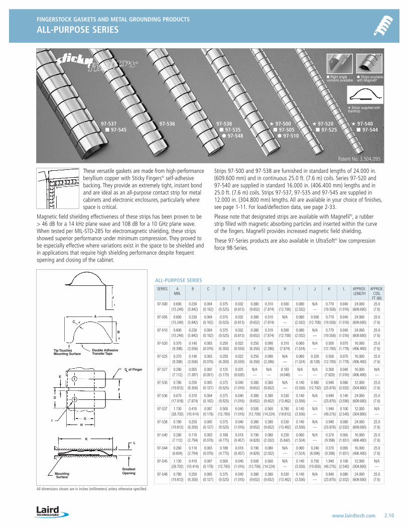
FINGERSTOCK GASKETS AND METAL GROUNDING PRODUCTS
ALL-PURPOSE SERIES
2.10www.lairdtech.com
All dimensions shown are in inches (millimeters) unless otherwise specified.
Right angle versions available
Strips availablewith Magnefil®
Strips supplied withteardrop
97-537 97-536 97-538 97-500 97-520 97-540 97-545 97-535 97-505 97-525 97-544
97-548 97-510
Patent No. 3,504,095
E
I
C
F
H
G
D
of Finger
KL
MountingSurface
Smallest Opening
L
A
B
C
Double AdhesiveTransfer Tape
Tip TouchesMounting Surface
These versatile gaskets are made from high-performanceberyllium copper with Sticky Fingers® self-adhesivebacking. They provide an extremely tight, instant bondand are ideal as an all-purpose contact strip for metalcabinets and electronic enclosures, particularly wherespace is critical.
Magnetic field shielding effectiveness of these strips has been proven to be> 46 dB for a 14 kHz plane wave and 108 dB for a 10 GHz plane wave.When tested per MIL-STD-285 for electromagnetic shielding, these stripsshowed superior performance under minimum compression. They proved tobe especially effective where variations exist in the space to be shielded andin applications that require high shielding performance despite frequentopening and closing of the cabinet.
Strips 97-500 and 97-538 are furnished in standard lengths of 24.000 in.(609.600 mm) and in continuous 25.0 ft. (7.6 m) coils. Series 97-520 and 97-540 are supplied in standard 16.000 in. (406.400 mm) lengths and in25.0 ft. (7.6 m) coils. Strips 97-537, 97-535 and 97-545 are supplied in12.000 in. (304.800 mm) lengths. All are available in your choice of finishes,see page 1-11. For load/deflection data, see page 2-33.
Please note that designated strips are available with Magnefil®, a rubberstrip filled with magnetic absorbing particles and inserted within the curve of the fingers. Magnefil provides increased magnetic field shielding.
These 97-Series products are also available in UltraSoft® low compressionforce 98-Series.
ALL-PURPOSE SERIES
SERIES A B C D E F G H I J K L APPROX. APPROX.MIN. LENGTH COIL
FT (M)97-500 0.600 0.230 0.004 0.375 0.032 0.380 0.310 0.500 0.080 N/A 0.770 0.040 24.000 25.0
(15.240) (5.842) (0.102) (9.525) (0.813) (9.652) (7.874) (12.700) (2.032) — (19.558) (1.016) (609.600) (7.6)
97-505 0.600 0.230 0.004 0.375 0.032 0.380 0.310 N/A 0.080 0.500 0.770 0.040 24.000 25.0(15.240) (5.842) (0.102) (9.525) (0.813) (9.652) (7.874) — (2.032) (12.700) (19.558) (1.016) (609.600) (7.6)
97-510 0.600 0.230 0.004 0.375 0.032 0.380 0.310 0.500 0.080 N/A 0.770 0.040 24.000 25.0(15.240) (5.842) (0.102) (9.525) (0.813) (9.652) (7.874) (12.700) (2.032) — (19.558) (1.016) (609.600) (7.6)
97-520 0.370 0.140 0.003 0.250 0.022 0.250 0.090 0.310 0.060 N/A 0.500 0.070 16.000 25.0(9.398) (3.556) (0.076) (6.350) (0.559) (6.350) (2.286) (7.874) (1.524) — (12.700) (1.778) (406.400) (7.6)
97-525 0.370 0.140 0.003 0.250 0.022 0.250 0.090 N/A 0.060 0.320 0.500 0.070 16.000 25.0(9.398) (3.556) (0.076) (6.350) (0.559) (6.350) (2.286) — (1.524) (8.128) (12.700) (1.778) (406.400) (7.6)
97-527 0.280 0.055 0.002 0.125 0.025 N/A N/A 0.183 N/A N/A 0.300 0.040 16.000 N/A(7.112) (1.397) (0.051) (3.175) (0.635) — — (4.648) — — (7.620) (1.016) (406.400) —
97-535 0.780 0.250 0.005 0.375 0.040 0.380 0.380 N/A 0.140 0.480 0.940 0.080 12.000 25.0(19.812) (6.350) (0.127) (9.525) (1.016) (9.652) (9.652) — (3.556) (12.192) (23.876) (2.032) (304.800) (7.6)
97-536 0.670 0.310 0.004 0.375 0.040 0.380 0.380 0.530 0.140 N/A 0.940 0.140 24.000 25.0(17.018) (7.874) (0.102) (9.525) (1.016) (9.652) (9.652) (13.462) (3.556) — (23.876) (3.556) (609.600) (7.6)
97-537 1.130 0.410 0.007 0.500 0.040 0.500 0.560 0.780 0.140 N/A 1.940 0.100 12.000 N/A(28.702) (10.414) (0.178) (12.700) (1.016) (12.700) (14.224) (19.812) (3.556) — (49.276) (2.540) (304.800) —
97-538 0.780 0.250 0.005 0.375 0.040 0.380 0.380 0.530 0.140 N/A 0.940 0.080 24.000 25.0(19.812) (6.350) (0.127) (9.525) (1.016) (9.652) (9.652) (13.462) (3.556) — (23.876) (2.032) (609.600) (7.6)
97-540 0.280 0.110 0.003 0.188 0.018 0.190 0.080 0.230 0.060 N/A 0.370 0.065 16.000 25.0(7.112) (2.794) (0.076) (4.775) (0.457) (4.826) (2.032) (5.842) (1.524) — (9.398) (1.651) (406.400) (7.6)
97-544 0.260 0.110 0.003 0.188 0.018 0.190 0.080 N/A 0.060 0.240 0.370 0.065 16.000 25.0(6.604) (2.794) (0.076) (4.775) (0.457) (4.826) (2.032) — (1.524) (6.096) (9.398) (1.651) (406.400) (7.6)
97-545 1.130 0.410 0.007 0.500 0.040 0.500 0.560 N/A 0.140 0.750 1.940 0.100 12.000 N/A(28.702) (10.414) (0.178) (12.700) (1.016) (12.700) (14.224) — (3.556) (19.050) (49.276) (2.540) (304.800) —
97-548 0.780 0.250 0.005 0.375 0.040 0.380 0.380 0.530 0.140 N/A 0.940 0.080 24.000 25.0(19.812) (6.350) (0.127) (9.525) (1.016) (9.652) (9.652) (13.462) (3.556) — (23.876) (2.032) (609.600) (7.6)
J
LT-3034 Metals_catalog 10/8/04 10:30 AM Page 2.10
FINGERSTOCK GASKETS AND METAL GROUNDING PRODUCTS
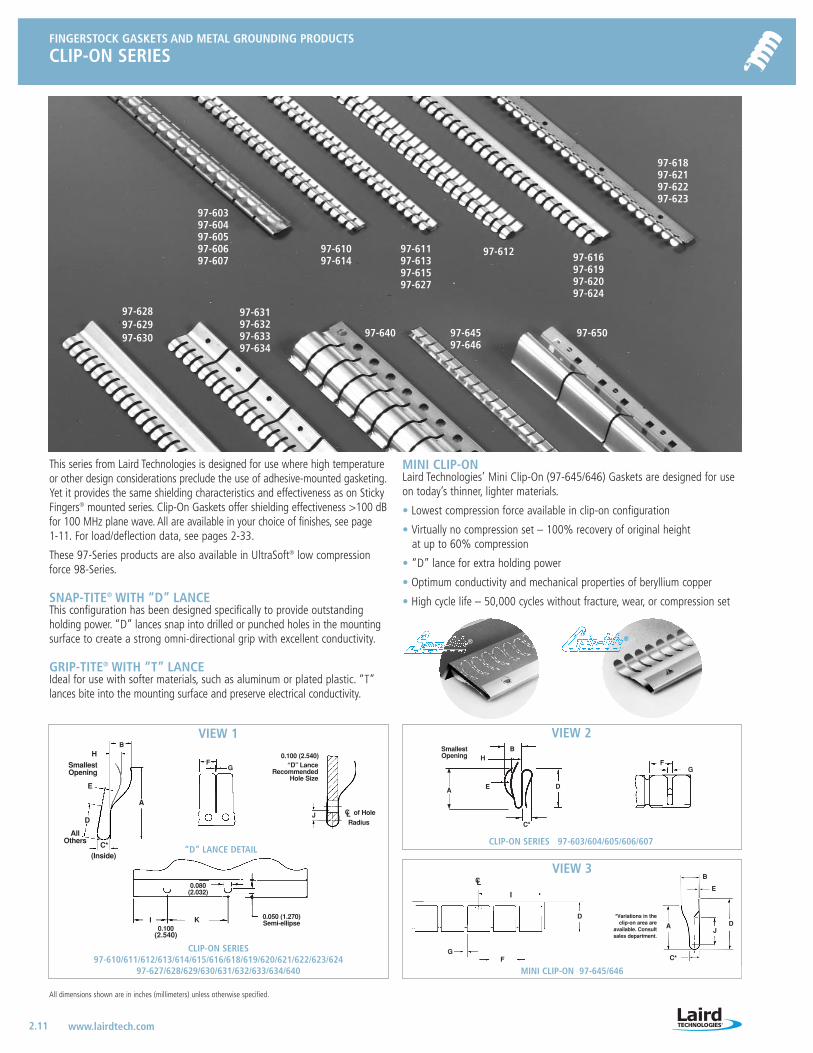
CLIP-ON SERIES
2.11 www.lairdtech.com
All dimensions shown are in inches (millimeters) unless otherwise specified.
D
FG
MINI CLIP-ON 97-645/646
B
D
H
E
C*
A
FG
CLIP-ON SERIES 97-603/604/605/606/607
CLIP-ON SERIES 97-610/611/612/613/614/615/616/618/619/620/621/622/623/624
97-627/628/629/630/631/632/633/634/640
CL
Smallest Opening
I
® ®
This series from Laird Technologies is designed for use where high temperatureor other design considerations preclude the use of adhesive-mounted gasketing.Yet it provides the same shielding characteristics and effectiveness as on StickyFingers® mounted series. Clip-On Gaskets offer shielding effectiveness >100 dBfor 100 MHz plane wave. All are available in your choice of finishes, see page 1-11. For load/deflection data, see pages 2-33.
These 97-Series products are also available in UltraSoft® low compressionforce 98-Series.
SNAP-TITE® WITH “D” LANCEThis configuration has been designed specifically to provide outstandingholding power. “D” lances snap into drilled or punched holes in the mountingsurface to create a strong omni-directional grip with excellent conductivity.
GRIP-TITE® WITH “T” LANCEIdeal for use with softer materials, such as aluminum or plated plastic. “T”lances bite into the mounting surface and preserve electrical conductivity.
MINI CLIP-ONLaird Technologies’ Mini Clip-On (97-645/646) Gaskets are designed for useon today’s thinner, lighter materials.
• Lowest compression force available in clip-on configuration
• Virtually no compression set – 100% recovery of original height at up to 60% compression
• “D” lance for extra holding power
• Optimum conductivity and mechanical properties of beryllium copper
• High cycle life – 50,000 cycles without fracture, wear, or compression set
0.100 (2.540)
Radiusof Hole
“D” LANCE DETAIL
AllOthers
SmallestOpening
HF
G
A
E
D
C*
0.080(2.032)
I K 0.050 (1.270) Semi-ellipse
“D” LanceRecommended
Hole Size
CL
0.100(2.540)
J
(Inside)
VIEW 1 VIEW 2
B
E
J
C*
A D
VIEW 3
B
97-618 97-62197-62297-623
97-65097-64597-646
97-640
97-63197-63297-63397-634
97-62897-62997-630
97-616 97-61997-62097-624
97-61297-61197-61397-615 97-627
97-61097-614
97-60397-60497-60597-60697-607
*Variations in theclip-on area are
available. Consultsales department.
LT-3034 Metals_catalog 10/8/04 10:30 AM Page 2.11
FINGERSTOCK GASKETS AND METAL GROUNDING PRODUCTS
CLIP-ON SERIES
2.12www.lairdtech.com
All dimensions shown are in inches (millimeters) unless otherwise specified.
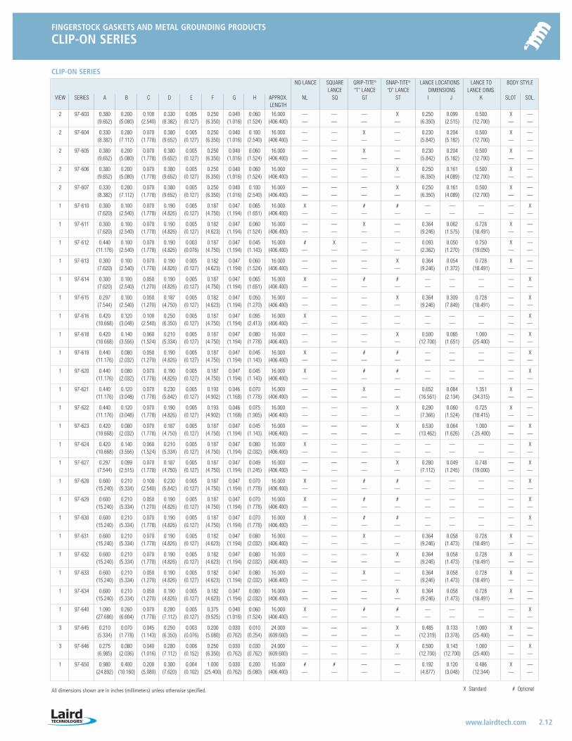
CLIP-ON SERIESNO LANCE SQUARE GRIP-TITE® SNAP-TITE® LANCE LOCATIONS LANCE TO BODY STYLE
LANCE “T” LANCE “D” LANCE DIMENSIONS LANCE DIMS.VIEW SERIES A B C D E F G H APPROX. NL SQ GT ST I J K SLOT SOL.
LENGTH
2 97-603 0.380 0.200 0.100 0.330 0.005 0.250 0.040 0.060 16.000 — — — X 0.250 0.099 0.500 X —(9.652) (5.080) (2.540) (8.382) (0.127) (6.350) (1.016) (1.524) (406.400) — — — — (6.350) (2.515) (12.700) — —
2 97-604 0.330 0.280 0.070 0.380 0.005 0.250 0.040 0.100 16.000 — — X — 0.230 0.204 0.500 X —(8.382) (7.112) (1.778) (9.652) (0.127) (6.350) (1.016) (2.540) (406.400) — — — — (5.842) (5.182) (12.700) — —
2 97-605 0.380 0.200 0.070 0.380 0.005 0.250 0.040 0.060 16.000 — — X — 0.230 0.204 0.500 X —(9.652) (5.080) (1.778) (9.652) (0.127) (6.350) (1.016) (1.524) (406.400) — — — — (5.842) (5.182) (12.700) — —
2 97-606 0.380 0.200 0.070 0.380 0.005 0.250 0.040 0.060 16.000 — — — X 0.250 0.161 0.500 X —(9.652) (5.080) (1.778) (9.652) (0.127) (6.350) (1.016) (1.524) (406.400) — — — — (6.350) (4.089) (12.700) — —
2 97-607 0.330 0.280 0.070 0.380 0.005 0.250 0.040 0.100 16.000 — — — X 0.250 0.161 0.500 X —(8.382) (7.112) (1.778) (9.652) (0.127) (6.350) (1.016) (2.540) (406.400) — — — — (6.350) (4.089) (12.700) — —
1 97-610 0.300 0.100 0.070 0.190 0.005 0.187 0.047 0.065 16.000 X — # # — — — — X(7.620) (2.540) (1.778) (4.826) (0.127) (4.750) (1.194) (1.651) (406.400) — — — — — — — — —
1 97-611 0.300 0.100 0.070 0.190 0.005 0.182 0.047 0.060 16.000 — — X — 0.364 0.062 0.728 X —(7.620) (2.540) (1.778) (4.826) (0.127) (4.623) (1.194) (1.524) (406.400) — — — — (9.246) (1.575) (18.491) — —
1 97-612 0.440 0.100 0.070 0.190 0.003 0.187 0.047 0.045 16.000 # X — — 0.093 0.050 0.750 X —(11.176) (2.540) (1.778) (4.826) (0.076) (4.750) (1.194) (1.143) (406.400) — — — — (2.362) (1.270) (19.050) — —
1 97-613 0.300 0.100 0.070 0.190 0.005 0.182 0.047 0.060 16.000 — — — X 0.364 0.054 0.728 X —(7.620) (2.540) (1.778) (4.826) (0.127) (4.623) (1.194) (1.524) (406.400) — — — — (9.246) (1.372) (18.491) — —
1 97-614 0.300 0.100 0.050 0.190 0.005 0.187 0.047 0.065 16.000 X — # # — — — — X(7.620) (2.540) (1.270) (4.826) (0.127) (4.750) (1.194) (1.651) (406.400) — — — — — — — — —
1 97-615 0.297 0.100 0.050 0.187 0.005 0.182 0.047 0.050 16.000 — — — X 0.364 0.309 0.728 — X(7.544) (2.540) (1.270) (4.750) (0.127) (4.623) (1.194) (1.270) (406.400) — — — — (9.246) (7.849) (18.491) — —
1 97-616 0.420 0.120 0.100 0.250 0.005 0.187 0.047 0.095 16.000 X — — — — — — — X(10.668) (3.048) (2.540) (6.350) (0.127) (4.750) (1.194) (2.413) (406.400) — — — — — — — — —
1 97-618 0.420 0.140 0.060 0.210 0.005 0.187 0.047 0.080 16.000 — — — X 0.500 0.065 1.000 — X(10.668) (3.556) (1.524) (5.334) (0.127) (4.750) (1.194) (1.778) (406.400) — — — — (12.700) (1.651) (25.400) — —
1 97-619 0.440 0.080 0.050 0.190 0.005 0.187 0.047 0.045 16.000 X — # # — — — — X(11.176) (2.032) (1.270) (4.826) (0.127) (4.750) (1.194) (1.143) (406.400) — — — — — — — — —
1 97-620 0.440 0.080 0.070 0.190 0.005 0.187 0.047 0.045 16.000 X — # # — — — — X(11.176) (2.032) (1.778) (4.826) (0.127) (4.750) (1.194) (1.143) (406.400) — — — — — — — — —
1 97-621 0.440 0.120 0.070 0.230 0.005 0.193 0.046 0.070 16.000 — — X — 0.652 0.084 1.351 X —(11.176) (3.048) (1.778) (5.842) (0.127) (4.902) (1.168) (1.778) (406.400) — — — — (16.561) (2.134) (34.315) — —
1 97-622 0.440 0.120 0.070 0.190 0.005 0.193 0.046 0.075 16.000 — — — X 0.290 0.060 0.725 X —(11.176) (3.048) (1.778) (4.826) (0.127) (4.902) (1.168) (1.905) (406.400) — — — — (7.366) (1.524) (18.415) — —
1 97-623 0.420 0.080 0.070 0.187 0.005 0.187 0.047 0.045 16.000 — — — X 0.530 0.064 1.000 — X(10.668) (2.032) (1.778) (4.750) (0.127) (4.750) (1.194) (1.143) (406.400) — — — — (13.462) (1.626) ( 25.400) — —
1 97-624 0.420 0.140 0.060 0.210 0.005 0.187 0.047 0.080 16.000 X — — — — — — — X(10.668) (3.556) (1.524) (5.334) (0.127) (4.750) (1.194) (2.032) (406.400) — — — — — — — — —
1 97-627 0.297 0.099 0.070 0.187 0.005 0.187 0.047 0.049 16.000 — — — X 0.280 0.049 0.748 — X(7.544) (2.515) (1.778) (4.750) (0.127) (4.750) (1.194) (1.245) (406.400) — — — — (7.112) (1.245) (19.000) — —
1 97-628 0.600 0.210 0.100 0.230 0.005 0.187 0.047 0.070 16.000 X — # # — — — — X(15.240) (5.334) (2.540) (5.842) (0.127) (4.750) (1.194) (1.778) (406.400) — — — — — — — — —
1 97-629 0.600 0.210 0.050 0.190 0.005 0.187 0.047 0.070 16.000 X — # # — — — — X(15.240) (5.334) (1.270) (4.826) (0.127) (4.750) (1.194) (1.778) (406.400) — — — — — — — — —
1 97-630 0.600 0.210 0.070 0.190 0.005 0.187 0.047 0.070 16.000 X — # # — — — — X(15.240) (5.334) (1.778) (4.826) (0.127) (4.750) (1.194) (1.778) (406.400) — — — — — — — — —
1 97-631 0.600 0.210 0.070 0.190 0.005 0.182 0.047 0.080 16.000 — — X — 0.364 0.058 0.728 X —(15.240) (5.334) (1.778) (4.826) (0.127) (4.623) (1.194) (2.032) (406.400) — — — — (9.246) (1.473) (18.491) — —
1 97-632 0.600 0.210 0.070 0.190 0.005 0.182 0.047 0.080 16.000 — — — X 0.364 0.058 0.728 X —(15.240) (5.334) (1.778) (4.826) (0.127) (4.623) (1.194) (2.032) (406.400) — — — — (9.246) (1.473) (18.491) — —
1 97-633 0.600 0.210 0.050 0.190 0.005 0.182 0.047 0.080 16.000 — — X — 0.364 0.058 0.728 X —(15.240) (5.334) (1.270) (4.826) (0.127) (4.623) (1.194) (2.032) (406.400) — — — — (9.246) (1.473) (18.491) — —
1 97-634 0.600 0.210 0.050 0.190 0.005 0.182 0.047 0.080 16.000 — — — X 0.364 0.058 0.728 X —(15.240) (5.334) (1.270) (4.826) (0.127) (4.623) (1.194) (2.032) (406.400) — — — — (9.246) (1.473) (18.491) — —
1 97-640 1.090 0.260 0.070 0.280 0.005 0.375 0.040 0.060 16.000 X — # # — — — — X(27.686) (6.604) (1.778) (7.112) (0.127) (9.525) (1.016) (1.524) (406.400) — — — — — — — — —
3 97-645 0.210 0.070 0.045 0.250 0.003 0.200 0.030 0.010 24.000 — — — X 0.485 0.133 1.000 X —(5.334) (1.778) (1.143) (6.350) (0.076) (5.080) (0.762) (0.254) (609.600) — — — — (12.319) (3.378) (25.400) — —
3 97-646 0.275 0.080 0.040 0.280 0.006 0.250 0.030 0.030 24.000 — — — X 0.500 0.143 1.000 — X(6.985) (2.036) (1.016) (7.112) (0.152) (6.350) (0.762) (0.762) (609.600) — — — — (12.700) (12.700) (25.400) — —
1 97-650 0.980 0.400 0.200 0.300 0.004 1.000 0.030 0.200 16.000 # # — — 0.192 0.120 0.486 X —(24.892) (10.160) (5.080) (7.620) (0.102) (25.400) (0.762) (5.080) (406.400) — — — — (4.877) (3.048) (12.344) — —
X Standard # Optional
LT-3034 Metals_catalog 10/8/04 10:30 AM Page 2.12
FINGERSTOCK GASKETS AND METAL GROUNDING PRODUCTS
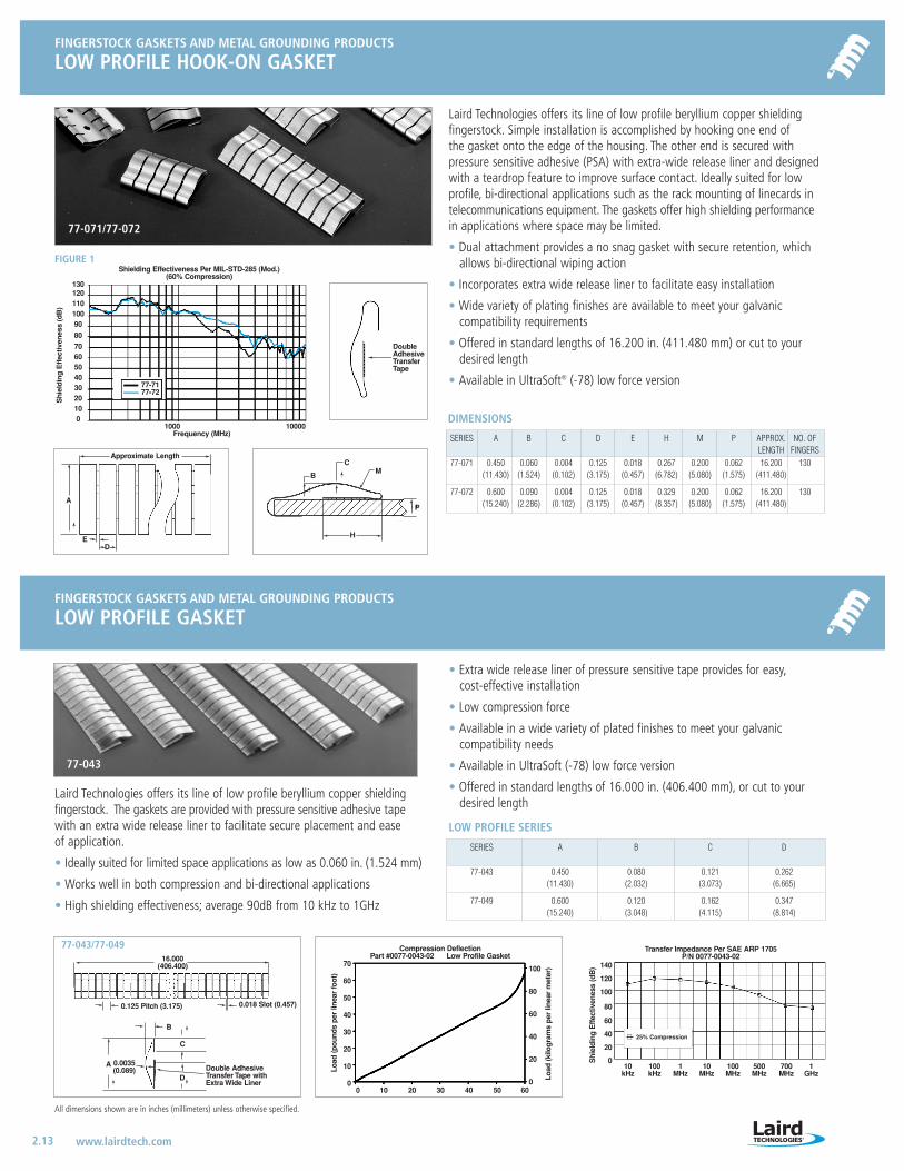
LOW PROFILE HOOK-ON GASKET
2.13 www.lairdtech.com
FINGERSTOCK GASKETS AND METAL GROUNDING PRODUCTS
LOW PROFILE GASKET
All dimensions shown are in inches (millimeters) unless otherwise specified.
Laird Technologies offers its line of low profile beryllium copper shielding fingerstock. Simple installation is accomplished by hooking one end of the gasket onto the edge of the housing. The other end is secured with pressure sensitive adhesive (PSA) with extra-wide release liner and designedwith a teardrop feature to improve surface contact. Ideally suited for lowprofile, bi-directional applications such as the rack mounting of linecards intelecommunications equipment. The gaskets offer high shielding performancein applications where space may be limited.
• Dual attachment provides a no snag gasket with secure retention, whichallows bi-directional wiping action
• Incorporates extra wide release liner to facilitate easy installation
• Wide variety of plating finishes are available to meet your galvanic compatibility requirements
• Offered in standard lengths of 16.200 in. (411.480 mm) or cut to yourdesired length
• Available in UltraSoft® (-78) low force version
• Extra wide release liner of pressure sensitive tape provides for easy,cost-effective installation
• Low compression force
• Available in a wide variety of plated finishes to meet your galvanic compatibility needs
• Available in UltraSoft (-78) low force version
• Offered in standard lengths of 16.000 in. (406.400 mm), or cut to yourdesired length
Approximate Length
E
A
D
B
CM
H
P
Shielding Effectiveness Per MIL-STD-285 (Mod.)(60% Compression)
1000 10000Frequency (MHz)
13012011010090
80
706050403020100
Shi
eldi
ng E
ffec
tiven
ess
(dB
)
77-7177-72
FIGURE 1
77-071/77-072
DoubleAdhesive TransferTape
Shi
eldi
ng E
ffec
tiven
ess
(dB
)
Transfer Impedance Per SAE ARP 1705P/N 0077-0043-02
25% Compression
140
120
100
80
60
40
20
010 100 1 10 100 500 700 1
kHz kHz MHz MHz MHz MHz MHz GHz
77-043
SERIES A B C D E H M P APPROX. NO. OFLENGTH FINGERS
77-071 0.450 0.060 0.004 0.125 0.018 0.267 0.200 0.062 16.200 130(11.430) (1.524) (0.102) (3.175) (0.457) (6.782) (5.080) (1.575) (411.480)
77-072 0.600 0.090 0.004 0.125 0.018 0.329 0.200 0.062 16.200 130(15.240) (2.286) (0.102) (3.175) (0.457) (8.357) (5.080) (1.575) (411.480)
DIMENSIONS
SERIES A B C D
77-043 0.450 0.080 0.121 0.262(11.430) (2.032) (3.073) (6.665)
77-049 0.600 0.120 0.162 0.347(15.240) (3.048) (4.115) (8.814)
LOW PROFILE SERIES
Laird Technologies offers its line of low profile beryllium copper shielding fingerstock. The gaskets are provided with pressure sensitive adhesive tapewith an extra wide release liner to facilitate secure placement and ease of application.
• Ideally suited for limited space applications as low as 0.060 in. (1.524 mm)
• Works well in both compression and bi-directional applications
• High shielding effectiveness; average 90dB from 10 kHz to 1GHz
Compression DeflectionPart #0077-0043-02 Low Profile Gasket
70
60
50
40
30
20
10
0
Load
(pou
nds
per
linea
r fo
ot)
0 10 20 30 40 50 60
100
80
60
40
20
0 Load
(kilo
gram
s pe
r lin
ear
met
er)
16.000(406.400)
0.125 Pitch (3.175) 0.018 Slot (0.457)
B
C
D
0.0035(0.089)
A
77-043/77-049
Double Adhesive Transfer Tape withExtra Wide Liner
LT-3034 Metals_catalog 10/8/04 10:30 AM Page 2.13

FINGERSTOCK GASKETS AND METAL GROUNDING PRODUCTS
LARGE ENCLOSURE SERIES
2.14www.lairdtech.com
FINGERSTOCK GASKETS AND METAL GROUNDING PRODUCTS
DOUBLE-SIDED CONTACT STRIPS
All dimensions shown are in inches (millimeters) unless otherwise specified.
SERIES A B C D E F G H I L APPROX.REF. MIN DIA. LENGTH
FT. (M)
97-438 1.090 0.250 0.005 0.375 0.040 0.160 0.380 0.140 1.270 0.080 25.000(27.686) (6.350) (0.127) (9.525) (1.016) (4.064) (9.652) (3.556) (32.258) (2.032) (7.6)
97-440 1.630 0.410 0.007 0.500 0.040 0.190 0.500 0.140 1.900 0.100 25.000(41.402) (10.414) (0.178) (12.700) (1.016) (4.826) (12.700) (3.556) (48.260) (2.540) (7.6)
LARGE ENCLOSURE SERIES
These standard beryllium copper contact gaskets offer ideal RFI/EMI shieldingof doors and movable components in electronic shielded rooms, trailers, computersand communication equipment.
They have been scientifically designed for wiping closures, but are also usablein compression applications. Moreover, these contact strips feature extremelygood endurance life, as well as a high deflection range. In tests, attenuationup to 112 dB has been measured for a 100 MHz plane wave. Fastening ofthe strip is usually accomplished using screws or rivets. Soldering is optional.
Both are available in continuous lengths to a maximum of 25.0 ft. (7.6 m) andin all standard finishes, see page 1-11. For load/deflection data, see page 2-33.
These 97-Series products are also available in UltraSoft® low compressionforce 98-Series.
97-440 97-438
A
B
C
H
D
G
F
E
L
I
Smallest Opening
KNIFE-EDGEMOUNT
Mechanically balanced strips with high deflection range and long endurancelife-provide a perfect fit as spring clips hold the gaskets firmly in place. Itmeans more simplified design and construction of cabinets and enclosures.Attenuation > 102 dB for a 100 MHz plane wave has been measured usingSeries 97-436 gaskets. For standard finishes, see page 1-11. For load/deflectiondata, see page 2-33. These 97-Series products are also available in UltraSoftlow compression force 98-Series.
QUICK SPRING CLIP FASTENERS (97-445)Designed for use with Series 97-436 finger gaskets, spring clip fasteners per-mit full strip compression. Easy to install, they permit lifting of gasket forcleaning of contact surface. Packaged in lots of 1,000. Available in standardfinishes, see page 1-11.
97-43697-436 97-445
97-436End View
SmallestOpening
97-436
97-445
0.250(6.350)
0.120(3.048)
1.060(26.924)
0.080(2.032)
0.004(0.102)
Free Position
0.940(23.876)
0.004(0.102)
0.250 Min.(6.350)
0.220(5.588)
1.090(27.686)
0.060(1.524)
0.130 x 0.160 Elongated(3.302 x 4.064) Holes
0.015 Slot(0.381)
0.375 Pitch(9.525)
^ Quick Spring Clip Fastener provides full stripcompression; allows lifting of product for cleaning ofcontact surface.
LT-3034 Metals_catalog 10/8/04 10:30 AM Page 2.14

2.15 www.lairdtech.com
All dimensions shown are in inches (millimeters) unless otherwise specified.
This version of Sticky Fingers® beryllium copper shielding gaskets features aspecial U-shaped end that permits the finger of the strip to slide when enclosuredoors are closed. It also retains the strip’s fingers when enclosure doors areopen, thus preventing accidental damage to the fingers. Shielding effectivenessis >115 dB for a 100 MHz plane wave.
Four models provide you a choice of widths to suit your application. They areavailable in standard 16.000 in. (406.400 mm) lengths, except 97-515 whichis furnished in 24.000 in. (609.600 mm) lengths. Also, all styles are available incontinuous 25.0 ft. (7.6 m) coils, and in your choice of all finishes except tinlead and satin tin, see page 1-11. For load/deflection data, see page 2-33.
These 97-Series products are also available in UltraSoft® low compressionforce 98-Series.
97-515 97-521 97-541 97-542
Patent No. 3,504,095
L
A
Double Adhesive Transfer Tape
B
I E
D
SmallestOpening
C
97-921
97-941
Patent No. 4,572,921
Series 97-941/921 are low compression, flexible beryllium copper contactstrips for applications where a continuous shield must conform to irregularshapes and turn tight radius corners in either direction.
Simple snap-in installation is possible for Series 97-921 with 0.250 in. (6.350mm) slots and 97-941 with 0.190 in. (4.826 mm) slots. However, soft solder orconductive adhesive can be used for mounting to flat surfaces.
Shielding effectiveness is >115 dB for a 100 MHz plane wave.
Available in standard 24.000 in. (609.600 mm) lengths in all standard finishes,see page 1-11. For load/deflection data, see page 2-33.
C
L
R
Q
A
B
FLAT BLANK
0 .047(1.194)
0.188(4.775)
FINGERSTOCK GASKETS AND METAL GROUNDING PRODUCTS
FOLDOVER SERIES
FINGERSTOCK GASKETS AND METAL GROUNDING PRODUCTS
FLEXIBLE LOW COMPRESSION SERIES
SERIES A B C D E I L APPROX. APPROX.PITCH SLOT DIA. LENGTH COIL
IN. (MM) FT. (M)97-515 0.760 0.230 0.004 0.375 0.032 0.080 0.060 24.000 25.0
(19.304) (5.842) (0.102) (9.525) (0.813) (2.032) (1.524) (609.600) (7.6)
97-521 0.510 0.140 0.003 0.250 0.022 0.060 0.070 16.000 25.0(12.954) (3.556) (0.076) (6.350) (0.559) (1.524) (1.778) (406.400) (7.6)
97-541 0.380 0.120 0.003 0.188 0.018 0.060 0.050 16.000 25.0(9.652) (3.048) (0.076) (4.775) (0.457) (1.524) (1.270) (406.400) (7.6)
97-542 0.250 0.080 0.003 0.188 0.018 0.060 0.050 16.000 25.0(6.350) (2.032) (0.076) (4.775) (0.457) (1.524) (1.270) (406.400) (7.6)
FOLDOVER SERIES
SERIES A B C L Q R APPROX.LENGTH
97-921 0.260 0.230 0.003 0.140 0.120 0.250 24.0(6.604) (5.842) (0.076) (3.556) (3.048) (6.350) (609.600)
97-941 0.200 0.170 0.003 0.110 0.090 0.190 24.0(5.080) (4.318) (0.076) (2.794) (2.286) (4.826) (609.600)
FLEXIBLE LOW COMPRESSION SERIES
LT-3034 Metals_catalog 10/8/04 10:30 AM Page 2.15
FINGERSTOCK GASKETS AND METAL GROUNDING PRODUCTS
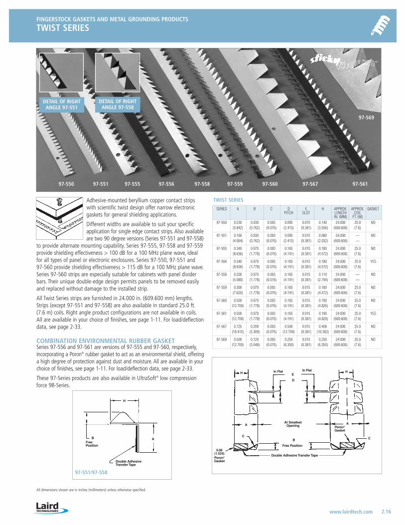
TWIST SERIES
2.16 www.lairdtech.com
All dimensions shown are in inches (millimeters) unless otherwise specified.
SERIES A B C D E H APPROX. APPROX. GASKETPITCH SLOT LENGTH COIL
IN. (MM) FT. (M)97-550 0.230 0.030 0.003 0.095 0.015 0.140 24.000 25.0 NO
(5.842) (0.762) (0.076) (2.413) (0.381) (3.556) (609.600) (7.6)
97-551 0.160 0.030 0.003 0.095 0.015 0.080 24.000 — NO(4.064) (0.762) (0.076) (2.413) (0.381) (2.032) (609.600) —
97-555 0.340 0.070 0.003 0.165 0.015 0.180 24.000 25.0 NO(8.636) (1.778) (0.076) (4.191) (0.381) (4.572) (609.600) (7.6)
97-556 0.340 0.070 0.003 0.165 0.015 0.180 24.000 25.0 YES(8.636) (1.778) (0.076) (4.191) (0.381) (4.572) (609.600) (7.6)
97-558 0.200 0.070 0.003 0.165 0.015 0.110 24.000 — NO(5.080) (1.778) (0.076) (4.191) (0.381) (2.794) (609.600) —
97-559 0.300 0.070 0.003 0.165 0.015 0.180 24.000 25.0 NO(7.620) (1.778) (0.076) (4.191) (0.381) (4.572) (609.600) (7.6)
97-560 0.500 0.070 0.003 0.165 0.015 0.190 24.000 25.0 NO(12.700) (1.778) (0.076) (4.191) (0.381) (4.826) (609.600) (7.6)
97-561 0.500 0.070 0.003 0.165 0.015 0.190 24.000 25.0 YES(12.700) (1.778) (0.076) (4.191) (0.381) (4.826) (609.600) (7.6)
97-567 0.725 0.209 0.003 0.500 0.015 0.408 24.000 25.0 NO(18.415) (5.309) (0.076) (12.700) (0.381) (10.363) (609.600) (7.6)
97-569 0.500 0.120 0.003 0.250 0.015 0.250 24.000 25.0 NO(12.700) (3.048) (0.076) (6.350) (0.381) (6.350) (609.600) (7.6)
TWIST SERIESAdhesive-mounted beryllium copper contact stripswith scientific twist design offer narrow electronicgaskets for general shielding applications.
Different widths are available to suit your specificapplication for single edge contact strips. Also availableare two 90 degree versions (Series 97-551 and 97-558)
to provide alternate mounting capability. Series 97-555, 97-558 and 97-559provide shielding effectiveness > 100 dB for a 100 MHz plane wave, idealfor all types of panel or electronic enclosures. Series 97-550, 97-551 and 97-560 provide shielding effectiveness > 115 dB for a 100 MHz plane wave.Series 97-560 strips are especially suitable for cabinets with panel dividerbars. Their unique double-edge design permits panels to be removed easilyand replaced without damage to the installed strip.
All Twist Series strips are furnished in 24.000 in. (609.600 mm) lengths.Strips (except 97-551 and 97-558) are also available in standard 25.0 ft.(7.6 m) coils. Right angle product configurations are not available in coils.All are available in your choice of finishes, see page 1-11. For load/deflectiondata, see page 2-33.
COMBINATION ENVIRONMENTAL RUBBER GASKETSeries 97-556 and 97-561 are versions of 97-555 and 97-560, respectively,incorporating a Poron® rubber gasket to act as an environmental shield, offeringa high degree of protection against dust and moisture. All are available in yourchoice of finishes, see page 1-11. For load/deflection data, see page 2-33.
These 97-Series products are also available in UltraSoft® low compressionforce 98-Series.
97-55597-551 97-556 97-558 97-559 97-560 97-567
97-569
97-561
DETAIL OF RIGHTANGLE 97-558
DETAIL OF RIGHTANGLE 97-551
97-550
A
H
BFreePosition
Double AdhesiveTransfer Tape
HE
D
C
A
BC
H
AAt Smallest
Opening Poron®
Gasket
In Flat In Flat
Free Position
Double Adhesive Transfer Tape
0.06(1.524)Poron®
Gasket
97-551/97-558
LT-3034 Metals_catalog 10/8/04 10:30 AM Page 2.16
FINGERSTOCK GASKETS AND METAL GROUNDING PRODUCTS
CLIP-ON TWIST SERIES
2.17 www.lairdtech.com
All dimensions shown are in inches (millimeters) unless otherwise specified.
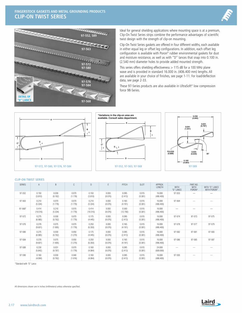
Ideal for general shielding applications where mounting space is at a premium,Clip-On Twist Series strips combine the performance advantages of scientifictwist design with the strength of clip-on mounting.
Clip-On Twist Series gaskets are offered in four different widths, each availablein either equal leg or offset leg configurations. In addition, each offset legconfiguration is available with Poron® rubber environmental gaskets for dustand moisture resistance, as well as with “D” lances that snap into 0.100 in.(2.540 mm) diameter holes to provide added mounted strength.
This series offers shielding effectiveness > 115 dB for a 100 MHz plane wave and is provided in standard 16.000 in. (406.400 mm) lengths. All are available in your choice of finishes, see page 1-11. For load/deflectiondata, see page 2-33.
These 97-Series products are also available in UltraSoft® low compressionforce 98-Series.
97-552, 589
97-563
97-57297-580
97-57697-584
A
C*
B
D
E
D
C*
A
E
B
*Variations in the clip-on area are available. Consult sales department.
DETAIL OF “D” LANCE
97-572, 97-580, 97-576, 97-584 97-552, 97-563, 97-568
97-568
97-589
CLIP-ON TWIST SERIES
SERIES A B C D E PITCH SLOT APPROX. PART NO.LENGTH WITH WITH WITH “D” LANCE
“D” LANCE PORON® WITH PORON®
97-552 0.150 0.030 0.070 0.150 0.003 0.095 0.015 16.000 97-553 — —(3.810) (0.762) (1.778) (3.810) (0.076) (2.413) (0.381) (406.400)
97-563 0.210 0.070 0.070 0.210 0.003 0.165 0.015 16.000 97-564 — —(5.334) (1.778) (1.778) (5.334) (0.076) (4.191) (0.381) (406.400)
97-568* 0.414 0.210 0.070 0.414 0.003 0.500 0.015 16.000 — — —(10.516) (5.334) (1.778) (10.516) (0.076) (12.700) (0.381) (406.400)
97-572 0.275 0.030 0.070 0.175 0.003 0.095 0.015 16.000 97-574 97-573 97-575(6.985) (0.762) (1.778) (4.445) (0.076) (2.413) (0.381) (406.400)
97-576 0.378 0.075 0.070 0.250 0.003 0.165 0.015 16.000 97-578 97-577 97-579(9.601) (1.905) (1.778) (6.350) (0.076) (4.191) (0.381) (406.400)
97-580 0.275 0.030 0.050 0.175 0.003 0.095 0.015 16.000 97-582 97-581 97-583(6.985) (0.762) (1.270) (4.445) (0.076) (2.413) (0.381) (406.400)
97-584 0.378 0.075 0.050 0.250 0.003 0.165 0.015 16.000 97-586 97-585 97-587(9.601) (1.905) (1.270) (6.350) (0.076) (4.191) (0.381) (406.400)
97-589 0.230 0.031 0.070 0.160 0.003 0.095 0.015 24.000 — — —(5.842) (0.787) (1.778) (4.064) (0.076) (2.413) (0.381) (609.000)
97-590 0.160 0.030 0.040 0.160 0.003 0.095 0.015 16.000 97-593 — —(4.064) (0.762) (1.016) (4.064) (0.076) (2.413) (0.381) (406.400)
*Standard with “D” Lance
0.230(5.842)
0.031(0.787)
30°
0.041(1.041)
0.025(0.635)
0.160(4.064)
R.0.035(0.889)
LT-3034 Metals_catalog 10/8/04 10:30 AM Page 2.17
FINGERSTOCK GASKETS AND METAL GROUNDING PRODUCTS
DIVIDER EDGE SHIELDING
2.18 www.lairdtech.com
FINGERSTOCK GASKETS AND METAL GROUNDING PRODUCTS
CARD GUIDE CLIP-ON
All dimensions shown are in inches (millimeters) unless otherwise specified.
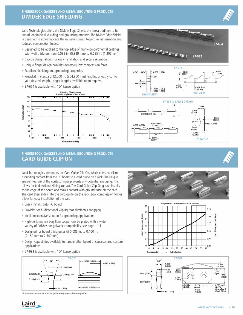
Laird Technologies offers the Divider Edge Shield, the latest addition to itsline of longitudinal shielding and grounding products. The Divider Edge Shieldis designed to accommodate the industry’s trend toward miniaturization andreduced compression forces.
• Designed to be applied to the top edge of multi-compartmental castingswith wall thickness from 0.035 in. (0.889 mm) to 0.055 in. (1.397 mm)
• Clip-on design allows for easy installation and secure retention
• Unique finger design provides extremely low compression force
• Excellent shielding and grounding properties
• Provided in standard 12.000 in. (304.800 mm) lengths, or easily cut toyour desired length. Longer lengths available upon request.
• 97-654 is available with “D” Lance option
Shielding EffectivenessTransfer Impedance Test 97-654
Frequency (Hz)
10K 100K 1M 10M 100M 1G
160
140
120
100
80
60
40
20
0
Att
enua
tion
(dB
)
97-972
97-973
0.008(0.203)
0.183 (4.648)
0.035(0.889)
0.020(0.508)
0.030(0.762)
0.208(5.283)
0.030 (0.762)
97-654 [D-LANCE OPTION]
0.020 (0.508) Slot
A
A
0.045 (1.143)
0.063 (1.600)
0.060 (1.524)
0.062 (1.575)0.055 (1.397)
20°
0.052(1.321)
0.030(0.762)
0.120(3.048)
0.157 Pitch(3.988)
FRONT VIEW SIDE VIEW
0.300 Pitch(7.620)
0.064(1.626)
0.115(2.921)
97-972
97-654
0.054 (1.372)
0.049 (1.245)
0.207 (5.258)
6.6°0.080
(2.032)
0.055(1.397)
0.050 (1.270)
0.076(1.930)
0.100(2.540)
0.175(4.445)
0.375(9.525)
0.194(4.928)
0.062(1.575)
0.086(2.184)Holes
0.050 x 45°(1.270)Cham Typ 2(Back Side)
97-983
Laird Technologies introduces the Card Guide Clip-On, which offers excellentgrounding contact from the PC board to a card guide on a rack. The uniquesnap-in feature of the contact finger prevents any potential snagging. Thisallows for bi-directional sliding contact. The Card Guide Clip-On gasket installsto the edge of the board and makes contact with ground trace on the card.The card then slides into the card guide on the rack. Low compression forcesallow for easy installation of the card.
• Easily installs onto PC board
• Provides for bi-directional wiping that eliminates snagging
• Ideal, inexpensive solution for grounding applications
• High-performance beryllium copper can be plated with a wide variety of finishes for galvanic compatibility, see page 1-11
• Designed for board thicknesses of 0.085 in. to 0.100 in.(2.159 mm to 2.540 mm)
• Design capabilities available to handle other board thicknesses and customapplications
• 97-983 is available with “D” Lance option
Compression Deflection Part No: 97-973-170.6
0.5
0.4
0.3
0.2
0.1
0.0
Load
(pou
nds
per
fing
er)
0.25
0.20
0.15
0.10
0.05
0.00
Load
(kilo
gram
s pe
r fin
ger
)
Compression % Deflection
0 5 10 15 20 25 30 35 40 45 50 55 60
VIEW A-A
34°
0.060 (1.524)
0.115 (2.921)
0.120 (3.048)
0.090 (2.286)
0.077 (1.956)
0.360 (9.144)
0.375 (9.525)
0.173 (4.394)
97-973
LT-3034 Metals_catalog 10/8/04 10:30 AM Page 2.18
FINGERSTOCK GASKETS AND METAL GROUNDING PRODUCTS
CLIP-ON PERPENDICULAR SHIELDING
2.19 www.lairdtech.com
FINGERSTOCK GASKETS AND METAL GROUNDING PRODUCTS
CLIP-ON PERPENDICULAR GROUNDING STRIP
All dimensions shown are in inches (millimeters) unless otherwise specified.
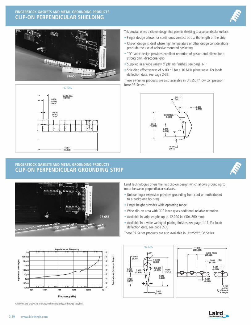
This product offers a clip-on design that permits shielding to a perpendicular surface.
• Finger design allows for continuous contact across the length of the strip
• Clip-on design is ideal where high temperature or other design considerationspreclude the use of adhesive-mounted gasketing
• “D” lance design provides excellent retention of gasket and allows for astrong omni directional grip
• Supplied in a wide variety of plating finishes, see page 1-11
• Shielding effectiveness of > 80 dB for a 10 MHz plane wave. For load/deflection data, see page 2-33.
These 97-Series products are also available in UltraSoft® low compressionforce 98-Series.
0.500 Adv.(12.700)
0.250(6.350)Pitch
0.030(0.762)
Slot
15.97(405.638)
0.035 Rad.(0.889)
0.250(6.350)
0.256(6.502)
0.544(13.818)
0.180(4.572)
30°Ref.
97-656
97-656
Laird Technologies offers the first clip-on design which allows grounding tooccur between perpendicular surfaces.
• Unique finger extension provides grounding from card or motherboard to a backplane housing
• Finger height provides wide operating range
• Wide clip-on area with “D” lance gives additional reliable retention
• Available in strip lengths up to 12.000 in. (304.800 mm)
• Available in a wide variety of plating finishes, see page 1-11. For load/deflection data, see page 2-33.
These 97-Series products are also available in UltraSoft®, 98-Series.
11.945(303.403)
0.545(13.843)
0.168(4.267)
0.045(1.143)
Slot
Pitch
0.250(6.350)
of Lance & Finger
0.080(2.032)
CL
45°
R 0.035(0.889)
0.305(7.747)
0.212(5.385)
0.055(1.397)
0.020(0.508)
0.129(3.277)
0.010(0.254)
R 0.035(0.889)
97-655
97-655
Impedance vs. Frequency
Con
duct
ance
(ohm
s pe
r fin
ger
)
Impe
danc
e (o
ne fi
nger
)
Frequency (Hz)
10K 100K 1M 10M 100M 1G
1Ω
100mΩ
10mΩ
1mΩ
100µΩ
10µΩ
1µΩ
100nΩ
10nΩ
100
101
102
103
104
105
106
107
108
0.083(2.108)
LT-3034 Metals_catalog 10/8/04 10:30 AM Page 2.19
FINGERSTOCK GASKETS AND METAL GROUNDING PRODUCTS
CLIP-ON LONGITUDINAL GROUNDING STRIP
2.20 www.lairdtech.com
FINGERSTOCK GASKETS AND METAL GROUNDING PRODUCTS
MINI-LONGITUDINAL GROUNDING GASKET
All dimensions shown are in inches (millimeters) unless otherwise specified.
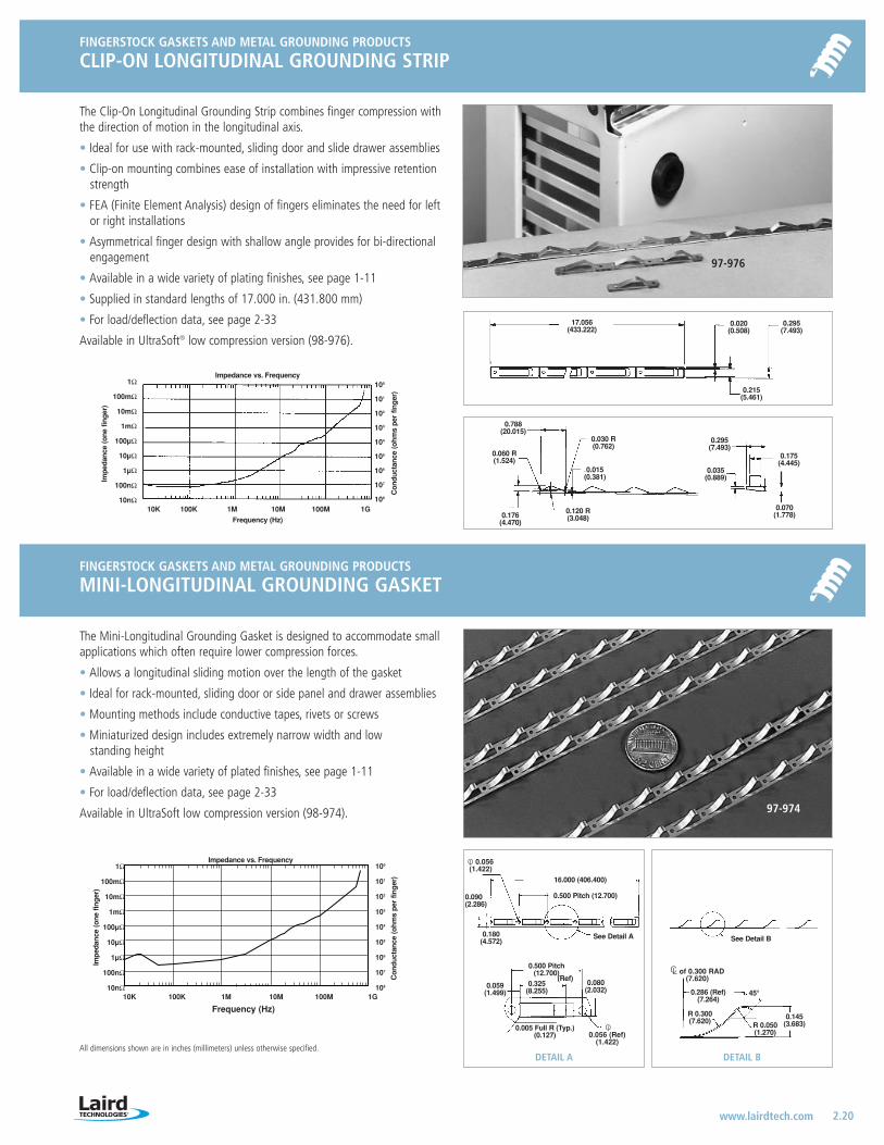
The Clip-On Longitudinal Grounding Strip combines finger compression withthe direction of motion in the longitudinal axis.
• Ideal for use with rack-mounted, sliding door and slide drawer assemblies
• Clip-on mounting combines ease of installation with impressive retentionstrength
• FEA (Finite Element Analysis) design of fingers eliminates the need for leftor right installations
• Asymmetrical finger design with shallow angle provides for bi-directionalengagement
• Available in a wide variety of plating finishes, see page 1-11
• Supplied in standard lengths of 17.000 in. (431.800 mm)
• For load/deflection data, see page 2-33
Available in UltraSoft® low compression version (98-976).
17.056(433.222)
0.020(0.508)
0.295(7.493)
0.215(5.461)
0.295(7.493)
0.175(4.445)
0.070(1.778)0.120 R
(3.048)0.176(4.470)
0.060 R(1.524)
0.788(20.015)
0.030 R(0.762)
0.015(0.381)
Impedance vs. Frequency
Con
duct
ance
(ohm
s pe
r fin
ger
)
Impe
danc
e (o
ne fi
nger
)
Frequency (Hz)
10K 100K 1M 10M 100M 1G
1Ω
100mΩ
10mΩ
1mΩ
100µΩ
10µΩ
1µΩ
100nΩ
10nΩ
100
101
102
103
104
105
106
107
108
0.035(0.889)
The Mini-Longitudinal Grounding Gasket is designed to accommodate smallapplications which often require lower compression forces.
• Allows a longitudinal sliding motion over the length of the gasket
• Ideal for rack-mounted, sliding door or side panel and drawer assemblies
• Mounting methods include conductive tapes, rivets or screws
• Miniaturized design includes extremely narrow width and low standing height
• Available in a wide variety of plated finishes, see page 1-11
• For load/deflection data, see page 2-33
Available in UltraSoft low compression version (98-974).
16.000 (406.400)
0.500 Pitch(12.700)
0.325(8.255)
0.059(1.499) 0.286 (Ref)
(7.264)
R 0.300(7.620)
0.145(3.683)
45°
R 0.050(1.270)
0.005 Full R (Typ.)(0.127)
CL of 0.300 RAD(7.620)
Ol 0.056 (Ref)
(1.422)
0.080(2.032)
0.500 Pitch (12.700)
0.180(4.572)
0.090(2.286)
See Detail A
DETAIL BDETAIL A
(Ref)
See Detail B
Ol 0.056(1.422)
97-974
Impedance vs. Frequency
Con
duct
ance
(ohm
s pe
r fin
ger
)
Impe
danc
e (o
ne fi
nger
)
Frequency (Hz)10K 100K 1M 10M 100M 1G
1Ω
100mΩ
10mΩ
1mΩ
100µΩ
10µΩ
1µΩ
100nΩ
10nΩ
100
101
102
103
104
105
106
107
108
97-976
LT-3034 Metals_catalog 10/8/04 10:30 AM Page 2.20

COMPRESSION FORCE COMPARISONStandard No. 97-541
UltraSoft No. 98-541Height (Millimeters)
Load
(Lbs
./lin
ear
ft.)
100
90
80
70
60
50
40
30
20
10
0
140
120
100
80
60
40
20
0
0.040 0.050 0.060 0.070 0.080 0.090 0.100 0.110 0.120
1.500 2.000 2.500 3.000
Load
(Kg/
linea
r m
)
Height (Inches)
FINGERSTOCK GASKETS AND METAL GROUNDING PRODUCTS
LONGITUDINAL GROUNDING SERIES
2.21 www.lairdtech.com
FINGERSTOCK GASKETS AND METAL GROUNDING PRODUCTS
ULTRASOFT® GASKET SERIES
All dimensions shown are in inches (millimeters) unless otherwise specified.
This series of beryllium copper strips combines finger compression with thedirection of motion in the longitudinal axis.
• Ideal for use with rack-mounted and slide drawer assemblies
• Provides reliable and complete grounds
• Typical installation methods include hardware mounting or use of theSticky Fingers® self-adhesive strip
• In standard finishes, see page 1-11
• For load/deflection data, see page 2-33
Available in UltraSoft® low compression verson (98-975).
0.300 Ref.(7.620)
Smallest Opening
0.070(1.778)
0.005(0.127)
0.050(1.270)
0.210(5.334)
0.210(5.334)Double
Adhesive Tape
1.250(31.750)
0.110 Dia.(2.794 Dia.)
0.600 Ref(15.240)
0.100 typ(2.540 typ)
1.250(31.750)
0.800(20.320)
0.380(9.652) Initial Compression
Against this Side
SERIES 97-975
Approx. Length 18.750 (476.250)
97-975
FOLDOVER SERIES
Standard No. 97-541
UltraSoft No. 98-541
SHIELDING EFFECTIVENESS COMPARISON
Most standard profiles shown on preceding pagesare available in 98-Series.®
Frequency (Hz)
10K 100K 1M 10M 100M 1G
Att
enua
tion
(dB
)
160
140
120
100
80
60
40
20
0
UltraSoft® fingers have been designed for communications, computers andelectronic systems designers concerned with EMI compliance and lightweightenclosure designs. Available in the same full range of standard configurations,UltraSoft fingers offer designers greater flexibility and versatility than everbefore—permitting more extensive use of lighter, thinner construction materialsto help cut costs and/or enhance system performance.
The unique advantages of UltraSoft (98-Series) fingers include:
• The lowest compression forces in the industry
• Increased life cycle
• Shielding effectiveness comparable to similarly configured standard 97-Series parts
• Wide selection of sizes and configurations
• Low compression force version available for virtually every standard shielding product
UltraSoft (98-Series) products are available in the same lengths as the standard(97-Series) products. Please refer to the appropriate standard product pagesfor specific information. All UltraSoft products are also available in yourchoice of finishes, see page 1-11. For load/deflection data, see page 2-33.
LT-3034 Metals_catalog 10/8/04 10:30 AM Page 2.21
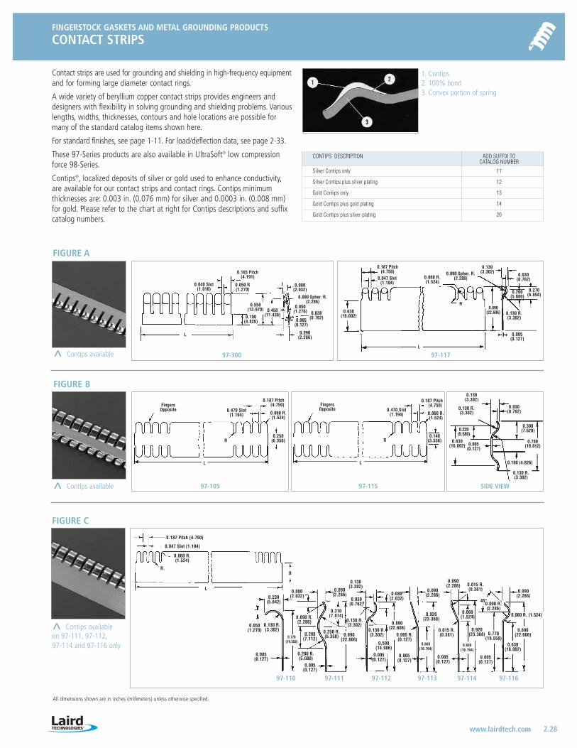
FINGERSTOCK GASKETS AND METAL GROUNDING PRODUCTS
CONTACT STRIPS
2.28 www.lairdtech.com
All dimensions shown are in inches (millimeters) unless otherwise specified.
Contact strips are used for grounding and shielding in high-frequency equipmentand for forming large diameter contact rings.
A wide variety of beryllium copper contact strips provides engineers anddesigners with flexibility in solving grounding and shielding problems. Variouslengths, widths, thicknesses, contours and hole locations are possible formany of the standard catalog items shown here.
For standard finishes, see page 1-11. For load/deflection data, see page 2-33.
These 97-Series products are also available in UltraSoft® low compressionforce 98-Series.
Contips®, localized deposits of silver or gold used to enhance conductivity,are available for our contact strips and contact rings. Contips minimum thicknesses are: 0.003 in. (0.076 mm) for silver and 0.0003 in. (0.008 mm)for gold. Please refer to the chart at right for Contips descriptions and suffixcatalog numbers.
1. Contips 2. 100% bond 3. Convex portion of spring
97-11797-300
FIGURE A
97-115 SIDE VIEW97-105
FIGURE B
FIGURE C
97-110 97-111 97-112 97-113 97-114 97-116
^ Contips availableon 97-111, 97-112,97-114 and 97-116 only
^ Contips available
^ Contips available
L
L
L
R
0.190(4.826)
FingersOpposite 0.470 Slot
(1.194)
0.187 Pitch(4.750)
0.060 R.(1.524)
0.250(6.350)
L
L
R
FingersOpposite 0.470 Slot
(1.194)
0.187 Pitch(4.750)
0.060 R.(1.524)
0.140(3.556) 0.630
(16.002)
0.187 Pitch (4.750)
0.047 Slot (1.194)
0.060 R.(1.524)
R.B
0.920(23.368)
0.005(0.127)
0.090(2.286) 0.015 R.
(0.381)0.090(2.286)0.230
(5.842)
0.050(1.270)
0.770(19.558)
0.200 R.(5.080)
0.005(0.127)
0.280(7.112)
0.080(2.032)
0.090(2.286)
0.130(3.302)
0.030(0.762)
0.890(22.606)
0.590(14.986)
0.890(22.606)
0.005 R.(0.127)
0.015 R.(0.381)
0.005(0.127)
0.660(16.764)
0.080(2.032)
0.310(7.874)0.090 R.
(2.286)
0.250 R.(6.350)
0.130 R.(3.302)
0.130 R.(3.302)
0.005(0.127)
0.130 R.(3.302)
0.005(0.127)
0.130 R.(3.302)
0.130(3.302)
0.030(0.762)
0.300(7.620)
0.780(19.812)
0.190 (4.826)
0.130 R.(3.302)
0.080(2.032)
0.550(13.970)
0.090(2.286)
0.630(16.002)
0.060 R.(1.524)
0.890(22.606) 0.130 R.
(3.302)
0.005(0.127)
0.130(3.302)
0.030(0.762)
0.270(6.858)0.200
(5.080)
R0.450
(11.430)0.005
(0.127)
0.090 Spher. R.(2.286)
0.090 Spher. R.(2.286)
0.187 Pitch(4.750)
0.047 Slot(1.194)0.050 R
(1.270)
0.165 Pitch(4.191)
0.040 Slot(1.016)
0.050(1.270) 0.030
(0.762)
0.220(5.588)
0.005(0.127)
0.060(1.524)
0.920(23.368)
0.660(16.764)
0.005(0.127)
0.770(19.558)
0.090 R.(2.286)
0.060 R. (1.524)
0.090 (2.286)
0.890 (22.606)
0.630 (16.002)
45°
CONTIPS DESCRIPTION ADD SUFFIX TOCATALOG NUMBER
Silver Contips only 11
Silver Contips plus silver plating 12
Gold Contips only 13
Gold Contips plus gold plating 14
Gold Contips plus silver plating 20
LT-3034 Metals_catalog 10/8/04 10:31 AM Page 2.28
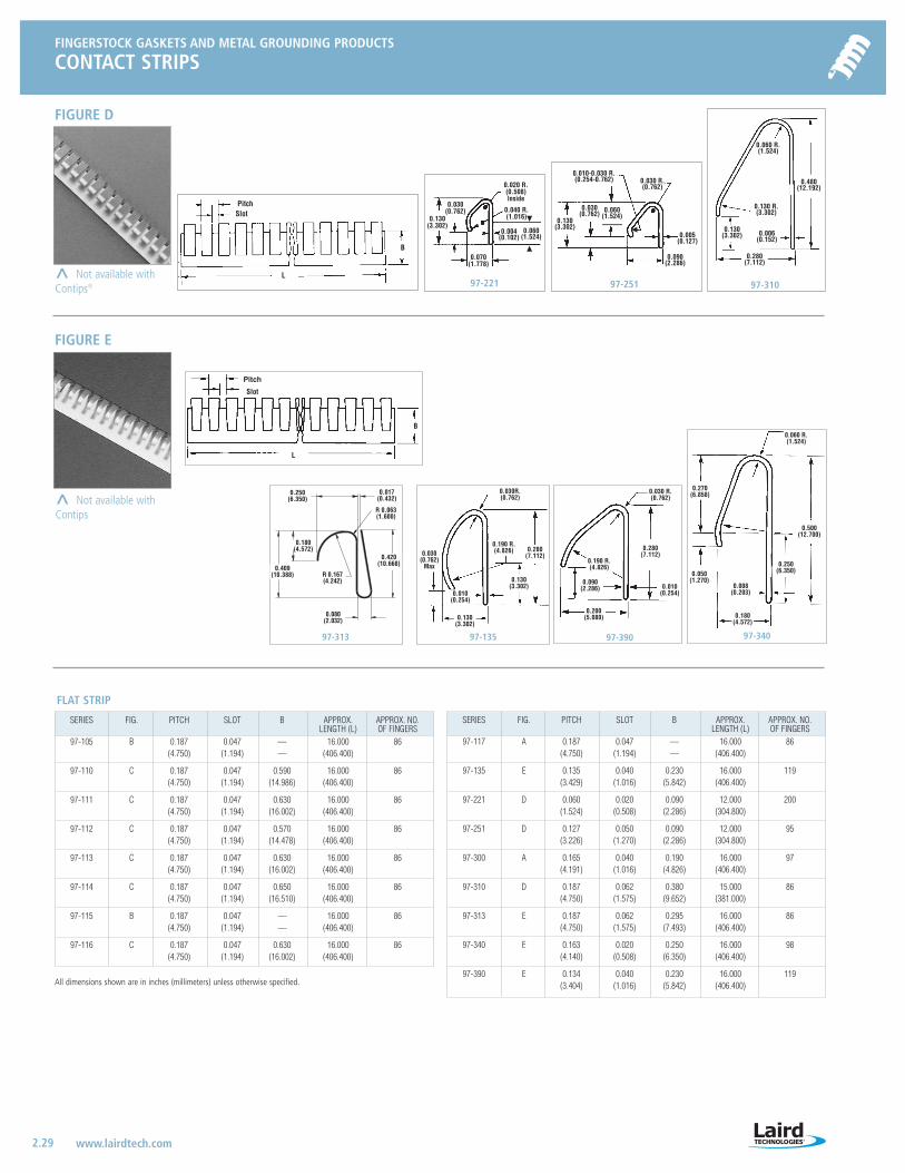
FINGERSTOCK GASKETS AND METAL GROUNDING PRODUCTS
CONTACT STRIPS
2.29 www.lairdtech.com
All dimensions shown are in inches (millimeters) unless otherwise specified.
97-221 97-251
97-34097-39097-135
97-310
Pitch
L
B
Slot
0.020 R.(0.508)Inside
0.040 R.(1.016)
0.004(0.102)
0.060(1.524)
0.130(3.302)
0.030(0.762) 0.060
(1.524)
0.090(2.286)
0.130(3.302)
0.280(7.112)
0.130 R.(3.302)
0.060 R.(1.524)
0.480(12.192)
0.005(0.127)
0.006(0.152)
0.030 R.(0.762)
0.010-0.030 R.(0.254-0.762)
0.070(1.778)
Pitch
Slot
L
B
0.030 R.(0.762)
0.190 R.(4.826)
0.030R.(0.762)
0.190 R.(4.826) 0.280
(7.112)
0.010(0.254)
0.090(2.286)
0.280(7.112)
0.130(3.302)
0.010(0.254)
0.130(3.302)
0.030(0.762)
Max
0.200(5.080)
0.270(6.858)
0.500(12.700)
0.060 R.(1.524)
0.008(0.203)
0.250(6.350)0.050
(1.270)
0.180(4.572)
0.030(0.762)
0.130(3.302)
FIGURE D
FIGURE E
^ Not available withContips®
^ Not available withContips
97-313
0.420(10.668)
R 0.063(1.600)
0.180(4.572)
0.017(0.432)
0.409(10.388)
0.250(6.350)
0.080(2.032)
R 0.167(4.242)
SERIES FIG. PITCH SLOT B APPROX. APPROX. NO.LENGTH (L) OF FINGERS
97-105 B 0.187 0.047 — 16.000 86(4.750) (1.194) — (406.400)
97-110 C 0.187 0.047 0.590 16.000 86(4.750) (1.194) (14.986) (406.400)
97-111 C 0.187 0.047 0.630 16.000 86(4.750) (1.194) (16.002) (406.400)
97-112 C 0.187 0.047 0.570 16.000 86(4.750) (1.194) (14.478) (406.400)
97-113 C 0.187 0.047 0.630 16.000 86(4.750) (1.194) (16.002) (406.400)
97-114 C 0.187 0.047 0.650 16.000 86(4.750) (1.194) (16.510) (406.400)
97-115 B 0.187 0.047 — 16.000 86(4.750) (1.194) — (406.400)
97-116 C 0.187 0.047 0.630 16.000 86(4.750) (1.194) (16.002) (406.400)
FLAT STRIP
SERIES FIG. PITCH SLOT B APPROX. APPROX. NO.LENGTH (L) OF FINGERS
97-117 A 0.187 0.047 — 16.000 86(4.750) (1.194) — (406.400)
97-135 E 0.135 0.040 0.230 16.000 119(3.429) (1.016) (5.842) (406.400)
97-221 D 0.060 0.020 0.090 12.000 200(1.524) (0.508) (2.286) (304.800)
97-251 D 0.127 0.050 0.090 12.000 95(3.226) (1.270) (2.286) (304.800)
97-300 A 0.165 0.040 0.190 16.000 97(4.191) (1.016) (4.826) (406.400)
97-310 D 0.187 0.062 0.380 15.000 86(4.750) (1.575) (9.652) (381.000)
97-313 E 0.187 0.062 0.295 16.000 86(4.750) (1.575) (7.493) (406.400)
97-340 E 0.163 0.020 0.250 16.000 98(4.140) (0.508) (6.350) (406.400)
97-390 E 0.134 0.040 0.230 16.000 119(3.404) (1.016) (5.842) (406.400)
LT-3034 Metals_catalog 10/8/04 10:31 AM Page 2.29
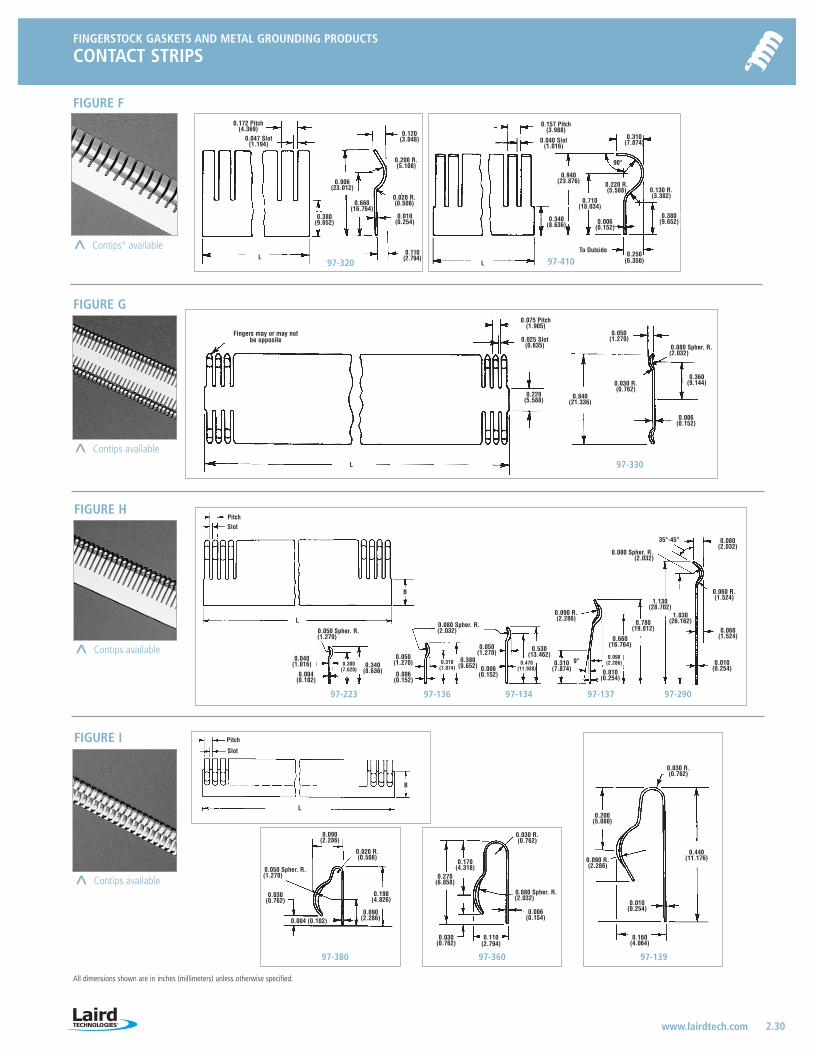
FINGERSTOCK GASKETS AND METAL GROUNDING PRODUCTS
CONTACT STRIPS
2.30 www.lairdtech.com
All dimensions shown are in inches (millimeters) unless otherwise specified.
97-330
97-223 97-136 97-134 97-137 97-290
97-320 97-410
97-380 97-360 97-139
0.120(3.048)
0.010(0.254)
0.660(16.764)
0.110(2.794)
0.220(5.588)
0.040(1.016)
0.004(0.102)
0.030(0.762)
0.004 (0.102)
0.090(2.286)
0.020 R.(0.508)
0.190(4.826)
0.090(2.286)
0.030(0.762)
0.006(0.154)
0.160(4.064)
0.010(0.254)
0.440(11.176)
0.030 R.(0.762)
0.200(5.080)
0.090 R.(2.286)
0.030 R.(0.762)
0.170(4.318)
0.270(6.858)
0.300(7.620)
0.340(8.636)
0.050(1.270)
0.006(0.152)
0.310(7.874)
0.380(9.652)
0.050(1.270)
0.006(0.152)
0.470(11.938)
0.530(13.462)
0.310(7.874)
0.090 R.(2.286)
0.090(2.286)
0.660(16.764)
0.780(19.812)
1.130(28.702)
0.010(0.254)
0.060(1.524)
0.060 R.(1.524)
0.080(2.032)
35°-45°
0.080 Spher. R.(2.032)
1.030(26.162)0.080 Spher. R.
(2.032)0.050 Spher. R.(1.270)
0.050 Spher. R.(1.270)
0.080 Spher. R.(2.032)
0.840(21.336)
0.030 R.(0.762)
PitchSlot
0.360(9.144)
0.006(0.152)
0.050(1.270)
0.080 Spher. R.(2.032)
L
0.340(8.636) 0.006
(0.152)
0.250(6.350)
0.380(9.652)
0.130 R.(3.302)
0.310(7.874)
0.220 R.(5.588)
90°
To Outside
0.157 Pitch(3.988)
0.040 Slot(1.016)
0.940(23.876)
0.710(18.034)
0.200 R.(5.108)
0.020 R.(0.508)
0.075 Pitch(1.905)
0.025 Slot(0.635)
0.906(23.012)
0.172 Pitch(4.369)
0.047 Slot(1.194)
L
L
L
B
Pitch
Slot
L
B
Fingers may or may not be opposite
0.380(9.652)
0.010(0.254)
9°
0.110(2.794)
FIGURE F
FIGURE G
FIGURE H
FIGURE I
^ Contips® available
^ Contips available
^ Contips available
^ Contips available
LT-3034 Metals_catalog 10/8/04 10:31 AM Page 2.30
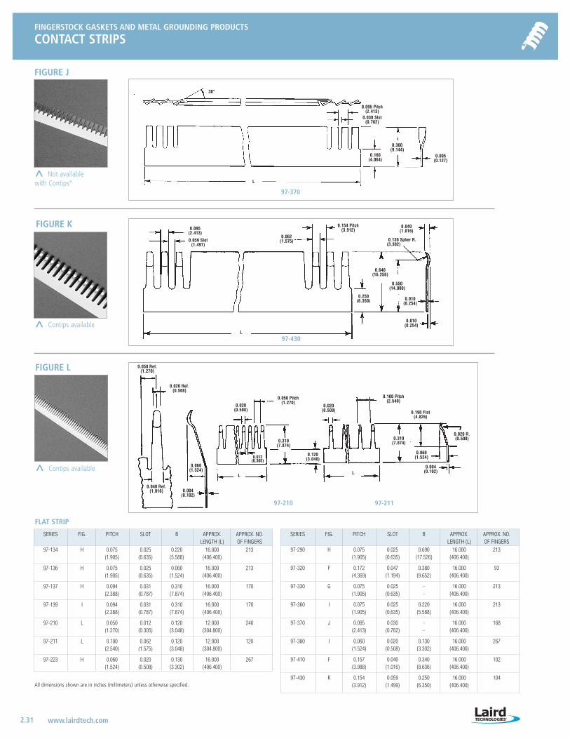
FINGERSTOCK GASKETS AND METAL GROUNDING PRODUCTS
CONTACT STRIPS
2.31 www.lairdtech.com
All dimensions shown are in inches (millimeters) unless otherwise specified.
97-210 97-211
97-430
97-370
30°
0.160(4.064)
0.062(1.575)
0.250(6.350)
0.040 Ref.(1.016)
0.050 Ref.(1.270)
0.020 Ref.(0.508)
0.004(0.102)
0.060(1.524)
0.020(0.508)
0.012(0.305)
0.050 Pitch(1.270)
0.310(7.874)
0.120(3.048)
0.020(0.508)
0.100 Pitch(2.540)
0.310(7.874)
0.190 Flat(4.826)
0.020 R.(0.508)
0.060(1.524)
0.004(0.102)
0.095(2.413)
0.095 Pitch(2.413)
0.154 Pitch(3.912)
0.130 Spher R.(3.302)
0.030 Slot(0.762)
0.059 Slot(1.497)
0.360(9.144)
0.640(16.256)
0.550(14.000)
0.010(0.254)
0.010(0.254)
0.040(1.016)
0.005(0.127)
L
L
LL
SERIES FIG. PITCH SLOT B APPROX. APPROX. NO.LENGTH (L) OF FINGERS
97-134 H 0.075 0.025 0.220 16.000 213(1.905) (0.635) (5.588) (406.400)
97-136 H 0.075 0.025 0.060 16.000 213(1.905) (0.635) (1.524) (406.400)
97-137 H 0.094 0.031 0.310 16.000 170(2.388) (0.787) (7.874) (406.400)
97-139 I 0.094 0.031 0.310 16.000 170(2.388) (0.787) (7.874) (406.400)
97-210 L 0.050 0.012 0.120 12.000 240(1.270) (0.305) (3.048) (304.800)
97-211 L 0.100 0.062 0.120 12.000 120(2.540) (1.575) (3.048) (304.800)
97-223 H 0.060 0.020 0.130 16.000 267(1.524) (0.508) (3.302) (406.400)
FLAT STRIP
SERIES FIG. PITCH SLOT B APPROX. APPROX. NO.LENGTH (L) OF FINGERS
97-290 H 0.075 0.025 0.690 16.000 213(1.905) (0.635) (17.526) (406.400)
97-320 F 0.172 0.047 0.380 16.000 93(4.369) (1.194) (9.652) (406.400)
97-330 G 0.075 0.025 - 16.000 213(1.905) (0.635) - (406.400)
97-360 I 0.075 0.025 0.220 16.000 213(1.905) (0.635) (5.588) (406.400)
97-370 J 0.095 0.030 - 16.000 168(2.413) (0.762) - (406.400)
97-380 I 0.060 0.020 0.130 16.000 267(1.524) (0.508) (3.302) (406.400)
97-410 F 0.157 0.040 0.340 16.000 102(3.988) (1.016) (8.636) (406.400)
97-430 K 0.154 0.059 0.250 16.000 104(3.912) (1.499) (6.350) (406.400)
FIGURE J
^ Not availablewith Contips®
FIGURE K
FIGURE L
^ Contips available
^ Contips available
LT-3034 Metals_catalog 10/8/04 10:31 AM Page 2.31

FINGERSTOCK GASKETS AND METAL GROUNDING PRODUCTS
CONTACT RINGS
2.32 www.lairdtech.com
All dimensions shown are in inches (millimeters) unless otherwise specified.
The large variety of sizes and shapes of contact rings offers engineers a widechoice in meeting design requirements for microwave cavities, tuning, shieldingand grounding applications. Rings are made from strip stock formed into anunclosed circle which, when assembled, becomes a complete ring. These ringsare furnished in any diameter, greater than the minimum shown in the chartbelow, and must contain an integral number of fingers.
Most configurations are available with Contips®, described in the precedingsection.
Available in standard finishes, see page 1-11.
97-76 97-422 TO 424 97-381
97-361 97-216 97-420
97-252 TO 255
0.030R.(0.762)
0.010-0.020R.(0.254-0.508)
0.060R.(1.524)
0.030R.(0.762)
0.190 R.(4.826)
0.020R.(0.508)
0.030R.(0.762)
0.030R.(0.762)
0.090R.(2.286)
0.090 R.(2.286)
0.170R.(4.318)
0.140 R.(3.556)
0.050 R.(1.270)
0.150R.(3.810)
PitchSlot
B
O.D.
0.060(1.524)
0.030(0.762)
0.050(1.270)
Spher. R.
0.080(2.032)
Spher. R.
0.050(1.270)
Spher. R.
0.005(0.127)
0.130(3.302)
0.500(12.700)
0.008(0.203)
0.150(3.810)
0.130(3.302) 0.280
(7.112) 0.030(0.762)
0.090(2.286)
0.110(2.794)
0.160(4.064)
0.440(11.176)
0.200(5.080)
0.010(0.254)
0.780(19.812)
0.310(7.874)
0.010(0.254)
0.090(2.286)
0.050(1.270)
0.660(16.764)0.300
(7.620)
0.340(8.636)
0.004(0.102)
0.080(2.032)
0.080(2.032)
0.018(0.457)
0.280(7.112)
0.090(2.286)
0.090(2.286)
0.410(10.414)
0.080(2.032)
0.100(2.540)
0.014(0.356)
0.280(7.112)
0.430(10.922)
0.040(1.016)
0.270(6.858)
0.030(0.762)
0.090(2.286)
0.090(2.286)
0.190(4.826)
0.004(0.102)
0.000 -0.030(0.000-0.762)
0.050(1.270)
0.270(6.858)
0.180(4.572)
0.090(2.286)
CONTIPS AVAILABLE
0.010(0.254)
0.006(0.153) 0.130
(3.302)
FEMALE RINGS
SERIES PITCH SLOT OD ~~ REC. B MADE SMALL# OF PIN FROM DIA. FROM
FINGERS DIAMETER STRIP STRIP
97-070 0.135 0.040 1.219 28 0.980 0.234 97-135 0.570(3.429) (1.016) (30.963) — (24.892) (5.944) (14.478)
97-072 0.135 0.040 1.000 23 0.790 0.234 97-135 0.570(3.429) (1.016) (25.400) — (20.066) (5.944) (14.478)
97-074 0.135 0.040 0.875 20 0.672 0.234 97-135 0.570(3.429) (1,016) (22.225) — (17.069) (5.944) (14.478)
97-076 0.163 0.020 0.640 12 0.340 0.250 97-340 0.640(4.140) (0.508) (16.256) — (8.636) (6.350) (16.256)
97-140 0.075 0.025 0.290 12 0.250 0.220 97-134 0.200(1.905) (0.635) (7.366) — (6.350) (5.588) (5.080)
97-141 0.075 0.025 0.440 18 0.380 0.220 97-134 0.200(1.905) (0.635) (11.176) — (9.652) (5.588) (5.080)
97-142 0.075 0.025 0.550 23 0.500 0.220 97-134 0.200(1.905) (0.635) (13.970) — (12.700) (5.588) (5.080)
97-143 0.075 0.025 0.800 33 0.750 0.220 97-134 0.200(1.905) (0.635) (20.320) — (19.050) (5.588) (5.080)
97-185 0.075 0.025 0.560 23 0.500 0.060 97-136 0.200(1.905) (0.635) (14.224) — (12.700) (1.524) (5.080)
97-204 0.094 0.031 1.040 34 1.000 0.310 97-137 0.460(2.388) (0.787) (26.416) — (25.400) (7.874) (11.684)
97-216 0.094 0.031 1.240 41 1.000 0.300 97-139 0.940(2.388) (0.787) (31.496) — (25.400) (7.620) (23.876)
97-232 0.060 0.020 0.540 28 0.500 0.130 97-233 0.160(1.524) (0.508) (13.716) — (12.700) (3.302) (4.064)
97-252 0.127 0.050 1.250 31 1.090 0.090 97-251 0.450(3.226) (1.270) (31.750) — (27.686) (2.286) (11.430)
97-254 0.127 0.050 0.910 22 0.740 0.090 97-251 0.450(3.226) (1.270) (23.114) — (18.796) (2.286) (11.430)
97-255 0.127 0.050 0.650 16 0.480 0.090 97-251 0.450(3.226) (1.270) (16.510) — (12.192) (2.286) (11.430)
97-361 0.075 0.025 1.010 42 0.840 0.220 97-360 0.610(1.905) (0.635) (25.654) - (21.336) (5.588) (15.494)
97-381 0.060 0.020 1.210 63 1.060 0.130 97-380 0.460(1.524) (0.508) (30.734) — (26.924) (3.302) (11.684)
97-420 0.190 0.075 0.500 8 0.320 0.060 N/A 0.500(4.826) (1.905) (12.700) — (8.128) (1.524) (12.700)
97-421 0.100 0.050 0.500 15 0.370 0.070 N/A 0.440(2.540) (1.270) (12.700) — (9.398) (1.778) (11.176)
97-422 0.154 0.059 0.600 12 0.370 0.250 N/A 0.550(3.912) (1.499) (15.240) — (9.398) (6.350) (13.970)
97-423 0.154 0.059 0.780 15 0.540 0.250 N/A 0.550(3.912) (1.499) (19.812) — (13.716) (6.350) (13.970)
97-424 0.135 0.040 1.050 24 0.810 0.230 N/A 0.870(3.429) (1.016) (26.670) — (20.574) (5.842) (22.098)
FEMALE RINGS
97-20497-23297-421
97-070, 072, 074
0.220R.(5.588)
0.010(0.254)
0.187(4.750) 0.281
(7.137)0.031
(0.787)
0.130(3.302)
0.027R(0.686)
LT-3034 Metals_catalog 10/8/04 10:31 AM Page 2.32

All dimensions shown are in inches (millimeters) unless otherwise specified.
FINGERSTOCK GASKETS AND METAL GROUNDING PRODUCTS
CONTACT RINGS
2.33 www.lairdtech.com
97-241
97-205 97-192 97-150 TO 156
0.040(1.016)
0.050(1.270)
Spher. R.
0.004(0.102)
0.340(8.636)
0.300(7.620)
0.030R.(0.762)
0.090R.(2.286)
0.030R.(0.762)
0.030R.(0.762)
0.080 (2.032)Sphere R.
0.080 (2.032)Sphere R.
0.050(1.270)
0.010(0.254)
0.200(5.080)
0.440(11.176)
0.080 (2.032)Sphere R.
0.080 (2.032)Sphere R.
0.030R.(0.762)
0.030R.(0.762)
0.050 (1.270) 0.006(0.153)
0.380(9.652)
0.006(0.153)
0.050(1.270) 0.470
(11.938)
0.530(13.462)
0.006(0.153)
0.050(1.270)
0.380(9.652)
0.530(13.462)
0.470(11.938)
0.006(0.153)
0.050(1.270)
0.310(7.874)
0.090R.(2.286)
0.050(1.270)
0.310(7.874)
0.010(0.254)
0.090(2.286)
0.660(16.764)
0.780(19.812)
MALE RINGS
CONTIPS® AVAILABLE
0.025(0.635) Slot
0.075(1.905) Pitch
B
I.D.
SERIES PITCH SLOT ID ~~ REC. B MADE# OF HOLE FROM
FINGERS SIZE STRIP97-150 0.075 0.025 0.210 9 0.250 0.220 97-134
(1.905) (0.635) (5.334) — (6.350) (5.588) —
97-151 0.075 0.025 0.330 14 0.380 0.220 97-134(1.905) (0.635) (8.382) — (9.652) (5.588) —
97-152 0.075 0.025 0.450 19 0.500 0.220 97-134(1.905) (0.635) (11.430) — (12.700) (5.588) —
97-153 0.075 0.025 0.690 29 0.750 0.220 97-134(1.905) (0.635) (17.526) — (19.050) (5.588) —
97-154 0.075 0.025 0.950 40 1.000 0.220 97-134(1.905) (0.635) (24.130) — (25.400) (5.588) —
97-155 0.075 0.025 1.450 61 1.500 0.220 97-134(1.905) (0.635) (36.830) — (38.100) (5.588) —
97-156 0.075 0.025 1.950 82 2.000 0.220 97-136(1.905) (0.635) (49.530) — (50.800) (5.588) —
97-192 0.075 0.025 0.450 19 0.500 0.060 97-136(1.905) (0.635) (11.430) — (12.700) (1.524) —
97-205 0.094 0.031 0.890 30 1.000 0.310 97-137(2.388) (0.787) (22.606) — (25.400) (7.874) —
97-215 0.094 0.031 1.240 42 1.500 0.310 97-139(2.388) (0.787) (31.496) — (38.100) (7.874) —
97-241 0.060 0.020 0.340 18 0.380 0.130 97-223(1.524) (0.508) (8.636) — (9.652) (3.302) —
MALE RINGS
FINGERSTOCK GASKETS AND METAL GROUNDING PRODUCTS
LOAD/DEFLECTION DATA
PART SMALLEST LARGEST NO. DEFLECTION DEFLECTION
DEFLECTION LOAD DEFLECTION LOAD DEFLECTION LOAD DEFLECTION LOAD DEFLECTION LOAD
INCHES LB/FT INCHES LB/FT INCHES LB/FT INCHES LB/FT INCHES LB/FT
(MM) (KG/M) (MM) (KG/M) (MM) (KG/M) (MM) (KG/M) (MM) (KG/M)
97-116 0.010 11 0.020 22 0.035 44 0.045 62 0.055 84(0.254) (16) (0.508) (33) (0.889) (65) (1.143) (92) (1.397) (125)
SAMPLE LOAD CHART FOR GROUNDING STRIPS
FINGERSTOCK LOAD DATAEfficient enclosure design requires an understanding of the compression forcenecessary to close gasketed joints. Toward this end, Laird Technologies hasdeveloped the following charts indicating compression forces required to achieveoptimum gasket performance from each of our fingerstock gaskets. Loads areexpressed in “pounds per linear foot” (or as “kilograms per linear meter”).
Load Tests: Bare BeCu mated against mild steel having a ground surface,roughness approx. 16 m in. (0.4 mm).
DEFINITIONS:Largest opening is the height at which contact force is the minimum requiredfor reliable shielding performance.Design height is the height which allows maximum deviation in both directions.This is recommended in most cases.Smallest opening is the smallest height which precludes damage to the gasket.
SHIELDING EFFECTIVENESSShielding effectiveness of fingerstock gaskets does not vary significantly withcompression. The graph below shows finger gaskets tested at five differentheights. Variation is only about 10 dB, which is typical of most fingerstockgaskets. Compression of a finger gasket beyond “design height” does notbenefit performance, but can complicate enclosure design.
GROUNDING STRIPSSome fingerstock products are used as grounding strips, or in other applicationscarrying RF current. Because these products are basically flat, their loads areexpressed as a function of “deflection” rather than height.
Free Position Deflection
Load
97-185 97-140 TO 14397-215
0.160(4.064)
PART NO. LARGEST OPENING DESIGN HEIGHT SMALLEST OPENINGHEIGHT LOAD HEIGHT LOAD HEIGHT LOAD HEIGHT LOAD HEIGHT LOAD
INCHES LB/FT INCHES LB/FT INCHES LB/FT INCHES LB/FT INCHES LB/FT(MM) (KG/M) (MM) (KG/M) (MM) (KG/M) (MM) (KG/M) (MM) (KG/M)
97-951 0.195 20 0.170 36 0.150 44 0.125 62 0.100 92(4.953) (30) (4.318) (53) (3.810) (65) (3.175) (92) (2.540) (137)
Load
Height
Free Position
120
110
100
90
80
70
60
50
010K 100K 1M 10M 100M 1G
Frequency (Hz)Shielding Effectiveness vs. Compression
SAMPLE LOAD CHART FOR EMI GASKETS
Att
enua
tion
(dB
)
LT-3034 Metals_catalog 10/8/04 10:31 AM Page 2.33

EMI GASKETSPART LARGEST DESIGN SMALLEST NO. OPENING HEIGHT OPENING
HEIGHT LOAD HEIGHT LOAD HEIGHT LOAD HEIGHT LOAD HEIGHT LOAD
INCHES LB/FT INCHES LB/FT INCHES LB/FT INCHES LB/FT INCHES LB/FT(MM) (KG/M) (MM) (KG/M) (MM) (KG/M) (MM) (KG/M) (MM) (KG/M)
77-010 0.055 10 0.045 21 0.035 34 0.025 47 0.015 62(1.397) (15) (1.143) (31.5) (0.889) (51) (0.635) (70.5) (0.381) (93)
77-011 12 12 0.095 29 0.070 48 0.045 74 0.020 121(3.048) (18) (2.413) (43.5) (1.778) (72) (1.143) (111) (0.508) (181.5)
77-012 .100 5 0.085 13 0.075 16 0.060 23 0.050 37(2.540) (7.5) (2.159) (19.5) (1.905) (24) (1.524) (34.5) (1.270) (55.5)
77-014 0.195 9 0.170 17 0.l40 25 0.115 32 0.090 44(4.953) (13.5) (4.318) (25.5) (3.556) (37.5) (2.921) (48) (2.286) (66)
77-023 0.069 0.19 0.058 0.41 0.047 0.67 0.036 1 0.025 1.377-024 (1.753) (0.285) (1.473) (0.615) (1.194) (1.005) (0.914) (1.5) (0.635) (1.95)
77-025 0.069 0.19 0.058 0.41 0.047 0.67 0.036 1 0.025 1.3(1.753) (0.285) (1.473) (0.615) (1.194) (1.005) (0.914) (1.5) (0.635) (1.95)
77-026 0.069 0.19 0.058 0.41 0.047 0.67 0.036 1 0.025 1.3(1.753) (0.285) (1.473) (0.615) (1.194) (1.005) (0.914) (1.5) (0.635) (1.95)
77-027 0.069 0.19 0.058 0.41 0.047 0.67 0.036 1 0.025 1.3(1.753) (0.285) (1.473) (0.615) (1.194) (1.005) (0.914) (1.5) (0.635) (1.95)
77-033 0.099 7.5 0.083 16 0.068 23 0.052 29.2 0.036 86(2.515) (11.25) (2.108) (24) (1.727) (34.5) (1.321) (43.8) (0.914) (129)
77-035 0.063 0.2 0.051 0.5 0.039 0.9 0.027 1.3 0.015 1.8(1.600) (0.3) (1.295) (0.75) (0.991) (1.35) (0.686) (1.95) (0.381) (2.7)
EMI GROUNDING STRIPSPART SMALLEST LARGEST NO. DEFLECTION DEFLECTION
DEFLECTION LOAD DEFLECTION LOAD DEFLECTION LOAD DEFLECTION LOAD DEFLECTION LOADINCHES LB/FT INCHES LB/FT INCHES LB/FT INCHES LB/FT INCHES LB/FT
(MM) (KG/M) (MM) (KG/M) (MM) (KG/M) (MM) (KG/M) (MM) (KG/M)
97-110 0.020 6 0.040 17 0.060 30 0.080 46 0.100 72(0.508) (9) (1.016) (25) (1.524) (45) (2.032) (68) (2.540) (107)
97-111 0.020 1 0.045 1.9 0.065 2.7 0.090 3.9 0.110 4.9(0.508) (1.5) (1.143) (2.8) (1.651) (4) (2.286) (5.8) (2.794) (7.3)
97-112 0.020 8 0.040 17 0.055 24 0.075 37 0.095 53(0.508) (11) (1.016) (25) (1.397) (36) (1.905) (54) (2.413) (79)
97-113 0.015 2 0.030 4.4 0.040 5.9 0.055 8.3 0.070 13.2(0.381) (3) (0.762) (6.5) (1.016) (8.8) (1.397) (12.4) (1.778) (19.6)
97-114 0.015 2.9 0.025 5.1 0.035 7.2 0.045 9.4 0.055 11.7(0.381) (4.3) (0.635) (7.6) (0.889) (10.7) (1.143) (14) (1.397) (17.4)
97-115 0.116 6 0.102 14 0.088 20 0.074 29 0.060 4897-105 (2.946) (8) (2.591) (21) (2.235) (29) (1.880) (42) (1.524) (71)
97-116 0.010 11 0.020 22 0.035 44 0.045 62 0.055 84(0.254) (16) (0.508) (33) (0.889) (65) (1.143) (92) (1.397) (125)
97-117 0.025 1.8 0.045 4.9 0.070 9.6 0.090 13.9 0.115 19.5(0.635) (2.7) (1.143) (7.3) (1.778) (14.3) (2.286) (20.7) (2.921) (29)
97-134 0.010 4.8 0.015 6.9 0.020 9.8 0.025 12.7 0.030 16.3(0.254) (7.1) (0.381) (10.3) (0.508) (14.6) (0.635) (18.9) (0.762) (24.3)
97-135 0.126 18 0.122 44 0.118 72 0.114 109 0.110 142(3.200) (27) (3.099) (65) (2.997) (107) (2.900) (162) (2.794) (211)
97-136 0.005 7 0.010 14 0.015 22 0.020 29 0.025 36(0.127) (10) (0.254) (20) (0.381) (32) (0.508) (43) (0.635) (54)
97-137 0.015 7 0.025 13 0.040 21 0.050 26 0.065 32(0.381) (10) (0.635) (19) (1.016) (31) (1.270) (38) (1.651) (48)
97-139 0.148 24 0.136 52 0.124 79 0.112 108 0.100 140(3.759) (36) (3.454) (77) (3.150) (118) (2.845) (161) (2.540) (208)
97-210 0.010 4 0.020 8 0.030 11 0.040 14 0.050 16(0.254) (6) (0.508) (11) (0.762) (16) (1.016) (21) (1.270) (24)
97-211 0.010 1.8 0.020 3.8 0.030 5.8 0.040 7.8 0.050 9.9(0.254) (2.7) (0.508) (5.7) (0.762) (8.6) (1.016) (11.6) (1.270) (14.7)
97-221 0.067 18 0.064 31 0.061 51 0.058 66 0.055 85(1.702) (27) (1.626) (46) (1.549) (76) (1.473) (98) (1.397) (126)
97-223 0.004 0.7 0.008 2.1 0.012 3.3 0.016 4.8 0.020 6.1(0.102) (1.0) (0.203) (3.1) (0.305) (4.9) (0.406) (7.1 ) (0.508) (9.1)
97-251 0.087 30 0.084 58 0.081 87 0.078 117 0.075 136(2.210) (45) (2.134) (86) (2.057) (129) (1.981) (174) (1.905) (202)
2.34 www.lairdtech.com
All dimensions shown are in inches (millimeters) unless otherwise specified.
FINGERSTOCK GASKETS AND METAL GROUNDING PRODUCTS
LOAD/DEFLECTION DATA
EMI GASKETSPART LARGEST DESIGN SMALLEST NO. OPENING HEIGHT OPENING
HEIGHT LOAD HEIGHT LOAD HEIGHT LOAD HEIGHT LOAD HEIGHT LOAD
INCHES LB/FT INCHES LB/FT INCHES LB/FT INCHES LB/FT INCHES LB/FT(MM) (KG/M) (MM) (KG/M) (MM) (KG/M) (MM) (KG/M) (MM) (KG/M)
97-290 0.007 3 0.014 7 0.022 16 0.029 25 0.036 34(0.178) (4) (0.356) (10) (0.559) (23) (0.737) (37) (0.914) (50)
97-300 0.020 4.6 0.040 9 0.060 14 0.080 19 0.100 25.4(0.508) (6.8) (1.016) (13.4) (1.524) (20.8) (2.032) (28.3) (2.540) (37.8)
97-310 0.255 3 0.230 6.5 0.200 10.5 0.175 14 0.150 25(6.477) (4.5) (5.842) (9.7) (5.080) (15.6) (4.445) (20.8) (3.810) (37.2)
97-320 0.015 31 0.025 52 0.040 88 0.050 118 0.065 158(0.381) (46) (0.635) (77) (1.016) (131) (1.270) (176) (1.651) (235)
97-340 0.170 10 0.160 22 0.145 52 0.135 91 0.125 168(4.318) (15) (4.064) (33) (3.683) (77) (3.429) (135) (3.175) (250)
97-360 0.102 9 0.094 19 0.086 30 0.078 41 0.070 78(2.591) (13) (2.388) (28) (2.184) (45) (1.981) (60) (1.778) (116)
97-370 0.028 34 0.025 64 0.023 94 0.020 132 0.018 156(0.711) (51) (0.635) (95) (0.584) (140) (0.508) (196 (0.457) (232)
97-380 0.084 10 0.078 19 0.072 30 0.066 40 0.060 53(2.133) (14) (1.981) (28) (1.829) (45) (1.676) (59) (1.524) (79)
97-390 0.193 23 0.186 55 0.179 90 0.172 138 0.165 183(4.902) (34) (4.724) (82) (4.547) (134) (4.369) (205) (4.191) (272)
97-410 0.040 5 0.080 10 0.120 18 0.160 29 0.200 42(1.016) (7) (2.032) (14) (3.048) (27) (4.064) (43) (5.080) (62)
97-430 .008 6 0.016 12 0.024 18 0.032 29 0.040 42(0.203) (8.93) (0.406) (17.86) (0.609) (26.79) (0.813) (43.16) (1.016) (62.50)
97-435 0.210 1.1 0.175 2 0.135 3.1 0.100 4 0.060 5.2(5.334) (1.6) (4.445) (3) (3.429) (4.6) (2.540) (6) (1.524) (7.7)
97-436 0.210 4 0.175 7.5 0.135 11.5 0.100 14.8 0.060 19.2(5.334) (6) (4.445) (11.2) (3.429) (17.1) (2.540) (22) (1.524) (28.6)
97-438 0.215 10 0.180 22 0.145 32 0.110 42 0.075 60(5.461) (15) (4.572) (33) (3.683) (48) (2.794) (62) (1.905) (89)
97-440 0.350 17 0.290 31 0.230 41 0.160 51 0.100 64(8.890) (25) (7.366) (46) (5.842) (61) (4.064) (75) (2.540) (95)
97-500 0.190 16 0.155 26 0.115 35 0.080 44 0.040 53(4.826) (24) (3.937) (39) (2.921) (52) (2.032) (65) (1.016) (78)
97-505 0.195 16 0.160 27 0.130 35 0.095 43 0.060 55(4.953) (24) (4.064) (40) (3.302) (52) (2.413) (63) (1.524) (81)
97-510 0.200 14 0.175 25 0.145 42 0.120 66 0.090 132(5.080) (21) (4.445) (37) (3.683) (62) (3.048) (98) (2.286) (196)
97-515 0.195 16 0.160 27 0.130 34 0.095 40 0.060 52(4.953) (23) (4.064) (40) (3.302) (50) (2.413) (60) (1.524) (77)
97-520 0.125 18 0.110 32 0.100 39 0.085 49 0.070 59(3.175) (27) (2.794) (48) (2.540) (58) (2.159) (73) (1.778) (88)
97-521 0.125 16 0.110 28 0.100 36 0.085 47 0.070 59(3.175) (24) (2.794) (42) (2.540) (54) (2.159) (70) (1.778) (88)
97-525 0.126 18 0.112 35 0.098 49 0.084 59 0.070 68(3.200) (27) (2.845) (52) (2.489) (73) (2.134) (88) (1.778) (101)
97-535 0.215 20 0.180 32 0.150 42 0.115 52 0.080 64(5.461) (29) (4.572) (48) (3.810) (62) (2.921) (77) (2.032) (95)
97-536 0.275 21 0.240 26 0.210 49 0.175 56 0.140 62(6.985) (31) (6.096) (38) (5.334) (73) (4.445) (83) (3.556) (92)
97-537 0.350 27 0.290 47 0.230 62 0.160 72 0.100 87(8.890) (40) (7.366) (69) (5.842) (92) (4.064) (107) (2.540) (129)
97-538 0.215 14 0.180 27 0.150 36 0.115 47 0.080 65(5.461) (20) (4.572) (40) (3.810) (54) (2.921) (69) (2.032) (97)
97-540 0.100 18 0.090 20 0.080 45 0.075 52 0.065 62(2.540) (27) (2.286) (30) (2.032) (66) (1.905) (77) (1.651) (92)
97-541 0.106 23 0.092 42 0.078 56 0.064 67 0.050 87(2.692) (34) (2.337) (62) (1.981) (83) (1.626) (100) (1.270) (129)
97-542 0.074 36 0.068 63 0.062 80 0.056 91 0.050 97(1.888) (0.53) (1.727) (94.5) (1.575) (120) (1.422) (182) (1.270) (194)
97-544 0.100 11 0.090 24 0.080 37 0.075 43 0.065 55(2.540) (16) (2.286 (36) (2.032) (55) (1.905) (63) (1.651) (81)
97-545 0.350 8 0.285 20 0.225 37 0.160 70 0.100 101(8.890) (12) (7.239) (30) (5.715) (55) (4.064) (105) (2.540) (152)
LT-3034 Metals_catalog 10/8/04 10:31 AM Page 2.34
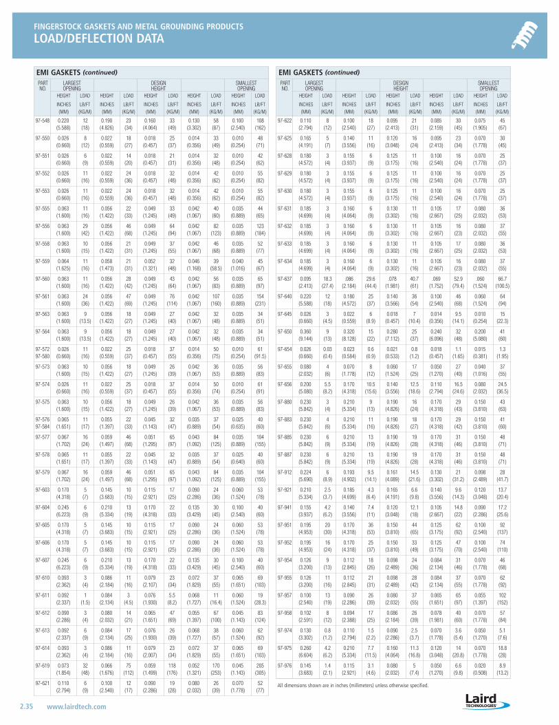
FINGERSTOCK GASKETS AND METAL GROUNDING PRODUCTS
LOAD/DEFLECTION DATA
2.35 www.lairdtech.com
All dimensions shown are in inches (millimeters) unless otherwise specified.
EMI GASKETS (continued)
PART LARGEST DESIGN SMALLEST NO. OPENING HEIGHT OPENING
HEIGHT LOAD HEIGHT LOAD HEIGHT LOAD HEIGHT LOAD HEIGHT LOAD
INCHES LB/FT INCHES LB/FT INCHES LB/FT INCHES LB/FT INCHES LB/FT(MM) (KG/M) (MM) (KG/M) (MM) (KG/M) (MM) (KG/M) (MM) (KG/M)
97-548 0.220 12 0.190 23 0.160 33 0.130 58 0.100 108(5.588) (18) (4.826) (34) (4.064) (49) (3.302) (87) (2.540) (162)
97-550 0.026 8 0.022 18 0.018 25 0.014 33 0.010 48(0.660) (12) (0.559) (27) (0.457) (37) (0.356) (49) (0.254) (71)
97-551 0.026 6 0.022 14 0.018 21 0.014 32 0.010 42(0.660) (9) (0.559) (20) (0.457) (31) (0.356) (48) (0.254) (62)
97-552 0.026 11 0.022 24 0.018 32 0.014 42 0.010 55(0.660) (16) (0.559) (36) (0.457) (48) (0.356) (62) (0.254) (82)
97-553 0.026 11 0.022 24 0.018 32 0.014 42 0.010 55(0.660) (16) (0.559) (36) (0.457) (48) (0.356) (62) (0.254) (82)
97-555 0.063 11 0.056 22 0.049 33 0.042 40 0.035 44(1.600) (16) (1.422) (33) (1.245) (49) (1.067) (60) (0.889) (65)
97-556 0.063 29 0.056 46 0.049 64 0.042 82 0.035 123(1.600) (42) (1.422) (68) (1.245) (94) (1.067) (123) (0.889) (184)
97-558 0.063 10 0.056 21 0.049 37 0.042 46 0.035 52(1.600) (15) (1.422) (31) (1.245) (55) (1.067) (68) (0.889) (77)
97-559 0.064 11 0.058 21 0.052 32 0.046 39 0.040 45(1.625) (16) (1.473) (31) (1.321) (48) (1.168) (58.5) (1.016) (67)
97-560 0.063 11 0.056 28 0.049 43 0.042 56 0.035 65(1.600) (16) (1.422) (42) (1.245) (64) (1.067) (83) (0.889) (97)
97-561 0.063 24 0.056 47 0.049 76 0.042 107 0.035 154(1.600) (36) (1.422) (69) (1.245) (114) (1.067) (160) (0.889) (231)
97-563 0.063 9 0.056 18 0.049 27 0.042 32 0.035 34(1.600) (13.5) (1.422) (27) (1.245) (40) (1.067) (48) (0.889) (51)
97-564 0.063 9 0.056 18 0.049 27 0.042 32 0.035 34(1.600) (13.5) (1.422) (27) (1.245) (40) (1.067) (48) (0.889) (51)
97-572 0.026 11 0.022 25 0.018 37 0.014 50 0.010 6197-580 (0.660) (16) (0.559) (37) (0.457) (55) (0.356) (75) (0.254) (91.5)
97-573 0.063 10 0.056 18 0.049 26 0.042 36 0.035 56(1.600) (15) (1.422) (27) (1.245) (39) (1.067) (53) (0.889) (83)
97-574 0.026 11 0.022 25 0.018 37 0.014 50 0.010 61(0.660) (16) (0.559) (37) (0.457) (55) (0.356) (74) (0.254) (91)
97-575 0.063 10 0.056 18 0.049 26 0.042 36 0.035 56(1.600) (15) (1.422) (27) (1.245) (39) (1.067) (53) (0.889) (83)
97-576 0.065 11 0.055 22 0.045 32 0.035 37 0.025 4097-584 (1.651) (17) (1.397) (33) (1.143) (47) (0.889) (54) (0.635) (60)
97-577 0.067 16 0.059 46 0.051 65 0.043 84 0.035 104(1.702) (24) (1.497) (68) (1.295) (97) (1.092) (125) (0.889) (155)
97-578 0.065 11 0.055 22 0.045 32 0.035 37 0.025 40(1.651) (17) (1.397) (33) (1.143) (47) (0.889) (54) (0.640) (60)
97-579 0.067 16 0.059 46 0.051 65 0.043 84 0.035 104(1.702) (24) (1.497) (68) (1.295) (97) (1.092) (125) (0.889) (155)
97-603 0.170 5 0.145 10 0.115 17 0.090 24 0.060 53(4.318) (7) (3.683) (15) (2.921) (25) (2.286) (36) (1.524) (78)
97-604 0.245 6 0.210 13 0.170 22 0.135 30 0.100 40(6.223) (9) (5.334) (19) (4.318) (33) (3.429) (45) (2.540) (60)
97-605 0.170 5 0.145 10 0.115 17 0.090 24 0.060 53(4.318) (7) (3.683) (15) (2.921) (25) (2.286) (36) (1.524) (78)
97-606 0.170 5 0.145 10 0.115 17 0.090 24 0.060 53(4.318) (7) (3.683) (15) (2.921) (25) (2.286) (36) (1.524) (78)
97-607 0.245 6 0.210 13 0.170 22 0.135 30 0.100 40(6.223) (9) (5.334) (19) (4.318) (33) (3.429) (45) (2.540) (60)
97-610 0.093 3 0.086 11 0.079 23 0.072 37 0.065 69(2.362) (4) (2.184) (16) (2.107) (34) (1.829) (55) (1.651) (103)
97-611 0.092 1 0.084 3 0.076 5.5 0.068 11 0.060 19(2.337) (1.5) (2.134) (4.5) (1.930) (8.2) (1.727) (16.4) (1.524) (28.3)
97-612 0.090 3 0.080 14 0.065 47 0.055 67 0.045 83(2.286) (4) (2.032) (21) (1.651) (69) (1.397) (100) (1.143) (124)
97-613 0.092 6 0.084 17 0.076 26 0.068 38 0.060 62(2.337) (9) (2.134) (25) (1.930) (39) (1.727) (57) (1.524) (92)
97-614 0.093 3 0.086 11 0.079 23 0.072 37 0.065 69(2.362) (4) (2.184) (16) (2.007) (34) (1.829) (55) (1.651) (103)
97-619 0.073 32 0.066 75 0.059 118 0.052 170 0.045 205(1.854) (48) (1.676) (112) (1.499) (176) (1.321) (253) (1.143) (305)
97-621 0.110 6 0.100 12 0.090 19 0.080 26 0.070 52(2.794) (9) (2.540) (17) (2.286) (28) (2.032) (39) (1.778) (77)
EMI GASKETS (continued)
PART LARGEST DESIGN SMALLEST NO. OPENING HEIGHT OPENING
HEIGHT LOAD HEIGHT LOAD HEIGHT LOAD HEIGHT LOAD HEIGHT LOAD
INCHES LB/FT INCHES LB/FT INCHES LB/FT INCHES LB/FT INCHES LB/FT(MM) (KG/M) (MM) (KG/M) (MM) (KG/M) (MM) (KG/M) (MM) (KG/M)
97-622 0.110 8 0.100 18 0.095 21 0.085 30 0.075 45(2.794) (12) (2.540) (27) (2.413) (31) (2.159) (45) (1.905) (67)
97-625 0.165 5 0.140 11 0.120 16 0.095 23 0.070 30(4.191) (7) (3.556) (16) (3.048) (24) (2.413) (34) (1.778) (45)
97-628 0.180 3 0.155 6 0.125 11 0.100 16 0.070 25(4.572) (4) (3.937) (9) (3.175) (16) (2.540) (24) (1.778) (37)
97-629 0.180 3 0.155 6 0.125 11 0.100 16 0.070 25(4.572) (4) (3.937) (9) (3.175) (16) (2.540) (24) (1.778) (37)
97-630 0.180 3 0.155 6 0.125 11 0.100 16 0.070 25(4.572) (4) (3.937) (9) (3.175) (16) (2.540) (24) (1.778) (37)
97-631 0.185 3 0.160 6 0.130 11 0.105 17 0.080 36(4.699) (4) (4.064) (9) (3.302) (16) (2.667) (25) (2.032) (53)
97-632 0.185 3 0.160 6 0.130 11 0.105 16 0.080 37(4.699) (4) (4.064) (9) (3.302) (16) (2.667) (23) (2.032) (55)
97-633 0.185 3 0.160 6 0.130 11 0.105 17 0.080 36(4.699) (4) (4.064) (9) (3.302) (16) (2.667) (25) (2.032) (53)
97-634 0.185 3 0.160 6 0.130 11 0.105 16 0.080 37(4.699) (4) (4.064) (9) (3.302) (16) (2.667) (23) (2.032) (55)
97-637 0.095 18.3 .086 29.6 .078 40.7 .069 52.9 .060 66.7(2.413) (27.4) (2.184) (44.4) (1.981) (61) (1.752) (79.4) (1.524) (100.5)
97-640 0.220 12 0.180 25 0.140 36 0.100 46 0.060 64(5.588) (18) (4.572) (37) (3.566) (54) (2.540) (68) (1.524) (94)
97-645 0.026 3 0.022 6 0.018 7 0.014 9.5 0.010 15(0.660) (4.5) (0.559) (8.9) (0.457) (10.4) (0.356) (14.1) (0.254) (22.3)
97-650 0.360 9 0.320 15 0.280 25 0.240 32 0.200 41(9.144) (13) (8.128) (22) (7.112) (37) (6.096) (48) (5.080) (60)
97-654 0.026 0.03 0.023 0.6 0.021 0.8 0.018 1.1 0.015 1.3(0.660) (0.4) (0.584) (0.9) (0.533) (1.2) (0.457) (1.65) (0.381) (1.95)
97-655 0.080 4 0.070 8 0.060 17 0.050 27 0.040 37(2.032) (6) (1.778) (12) (1.524) (25) (1.270) (40) (1.016) (55)
97-656 0.200 5.5 0.170 10.5 0.140 12.5 0.110 16.5 0.080 24.5(5.080) (8.2) (4.318) (15.6) (3.556) (18.6) (2.794) (24.6) (2.032) (36.5)
97-880 0.230 3 0.210 9 0.190 16 0.170 29 0.150 43(5.842) (4) (5.334) (13) (4.826) (24) (4.318) (43) (3.810) (63)
97-883 0.230 4 0.210 11 0.190 18 0.170 29 0.150 41(5.842) (6) (5.334) (16) (4.826) (27) (4.318) (42) (3.810) (60)
97-885 0.230 6 0.210 13 0.190 19 0.170 31 0.150 48(5.842) (9) (5.334) (19) (4.826) (28) (4.318) (46) (3.810) (71)
97-887 0.230 6 0.210 13 0.190 19 0.170 31 0.150 48(5.842) (9) (5.334) (19) (4.826) (28) (4.318) (46) (3.810) (71)
97-912 0.224 6 0.193 9.5 0.161 14.5 0.130 21 0.098 28(5.690) (8.9) (4.902) (14.1) (4.089) (21.6) (3.302) (31.2) (2.489) (41.7)
97-921 0.210 2.5 0.185 4.3 0.165 6.6 0.140 9.6 0.120 13.7(5.334) (3.7) (4.699) (6.4) (4.191) (9.8) (3.556) (14.3) (3.048) (20.4)
97-941 0.155 4.2 0.140 7.4 0.120 12.1 0.105 14.8 0.090 17.2(3.937) (6.2) (3.556) (11) (3.048) (18) (2.667) (22) (2.286) (25.6)
97-951 0.195 20 0.170 36 0.150 44 0.125 62 0.100 92(4.953) (30) (4.318) (53) (3.810) (65) (3.175) (92) (2.540) (137)
97-952 0.195 16 0.170 25 0.150 33 0.125 47 0.100 74(4.953) (24) (4.318) (37) (3.810) (49) (3.175) (70) (2.540) (110)
97-954 0.126 9 0.112 18 0.098 24 0.084 31 0.070 46(3.200) (13) (2.845) (26) (2.489) (36) (2.134) (46) (1.778) (68)
97-955 0.126 11 0.112 21 0.098 28 0.084 37 0.070 62(3.200) (16) (2.845) (31) (2.489) (42) (2.134) (55) (1.778) (92)
97-957 0.100 13 0.090 26 0.080 37 0.065 65 0.055 102(2.540) (19) (2.286) (39) (2.032) (55) (1.651) (97) (1.397) (152)
97-958 0.102 8 0.094 17 0.086 26 0.078 40 0.070 57(2.591) (12) (2.388) (25) (2.184) (39) (1.981) (60) (1.778) (84)
97-974 0.130 0.8 0.110 1.5 0.090 2.5 0.070 3.6 0.050 5.1(3.302) (1.2) (2.794) (2.2) (2.286) (3.7) (1.778) (5.4) (1.270) (7.6)
97-975 0.260 4.2 0.210 7.7 0.160 11.3 0.120 14 0.070 18.8(6.604) (6.2) (5.334) (11.5) (4.064) (16.8) (3.048) (20.8) (1.778) (28)
97-976 0.145 1.4 0.115 3.1 0.080 5 0.050 6.6 0.020 8.9(3.683) (2.1) (2.921) (4.6) (2.032) (7.4) (1.270) (9.8) (0.508) (13.2)
LT-3034 Metals_catalog 10/8/04 10:31 AM Page 2.35
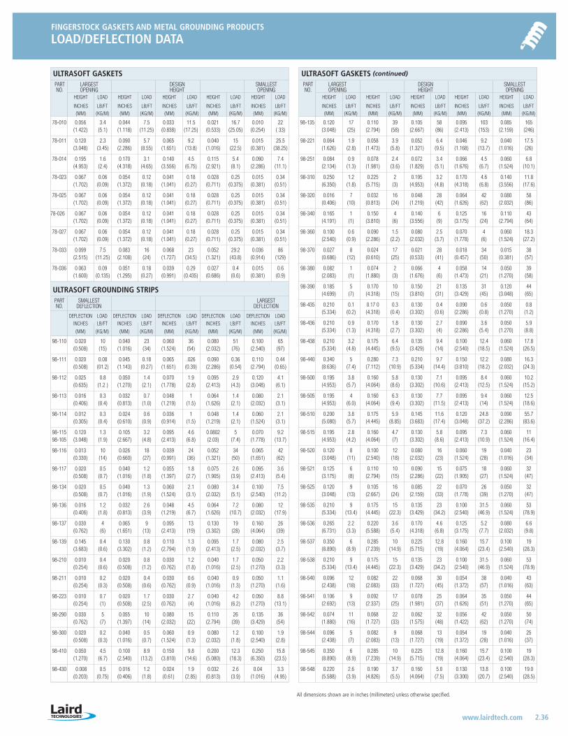
FINGERSTOCK GASKETS AND METAL GROUNDING PRODUCTS
LOAD/DEFLECTION DATA
2.36 www.lairdtech.com
All dimensions shown are in inches (millimeters) unless otherwise specified.
ULTRASOFT GASKETSPART LARGEST DESIGN SMALLEST NO. OPENING HEIGHT OPENING
HEIGHT LOAD HEIGHT LOAD HEIGHT LOAD HEIGHT LOAD HEIGHT LOAD
INCHES LB/FT INCHES LB/FT INCHES LB/FT INCHES LB/FT INCHES LB/FT(MM) (KG/M) (MM) (KG/M) (MM) (KG/M) (MM) (KG/M) (MM) (KG/M)
78-010 0.056 3.4 0.044 7.5 0.033 11.5 0.021 16.7 0.010 22(1.422) (5.1) (1.118) (11.25) (0.838) (17.25) (0.533) (25.05) (0.254) ( 33)
78-011 0.120 2.3 0.090 5.7 0.065 9.2 0.040 15 0.015 25.5(3.048) (3.45) (2.286) (8.55) (1.651) (13.8) (1.016) (22.5) (0.381) (38.25)
78-014 0.195 1.6 0.170 3.1 0.140 4.5 0.115 5.4 0.090 7.4(4.953) (2.4) (4.318) (4.65) (3.556) (6.75) (2.921) (8.1) (2.286) (11.1)
78-023 0.067 0.06 0.054 0.12 0.041 0.18 0.028 0.25 0.015 0.34(1.702) (0.09) (1.372) (0.18) (1.041) (0.27) (0.711) (0.375) (0.381) (0.51)
78-025 0.067 0.06 0.054 0.12 0.041 0.18 0.028 0.25 0.015 0.34(1.702) (0.09) (1.372) (0.18) (1.041) (0.27) (0.711) (0.375) (0.381) (0.51)
78-026 0.067 0.06 0.054 0.12 0.041 0.18 0.028 0.25 0.015 0.34(1.702) (0.09) (1.372) (0.18) (1.041) (0.27) (0.711) (0.375) (0.381) (0.51)
78-027 0.067 0.06 0.054 0.12 0.041 0.18 0.028 0.25 0.015 0.34(1.702) (0.09) (1.372) (0.18) (1.041) (0.27) (0.711) (0.375) (0.381) (0.51)
78-033 0.099 7.5 0.083 16 0.068 23 0.052 29.2 0.036 86(2.515) (11.25) (2.108) (24) (1.727) (34.5) (1.321) (43.8) (0.914) (129)
78-036 0.063 0.09 0.051 0.18 0.039 0.29 0.027 0.4 0.015 0.6(1.600) (0.135) (1.295) (0.27) (0.991) (0.435) (0.686) (0.6) (0.381) (0.9)
ULTRASOFT GROUNDING STRIPSPART SMALLEST LARGEST NO. DEFLECTION DEFLECTION
DEFLECTION LOAD DEFLECTION LOAD DEFLECTION LOAD DEFLECTION LOAD DEFLECTION LOADINCHES LB/FT INCHES LB/FT INCHES LB/FT INCHES LB/FT INCHES LB/FT
(MM) (KG/M) (MM) (KG/M) (MM) (KG/M) (MM) (KG/M) (MM) (KG/M)
98-110 0.020 10 0.040 23 0.060 36 0.080 51 0.100 65(0.508) (15) (1.016) (34) (1.524) (54) (2.032) (76) (2.540) (97)
98-111 0.020 0.08 0.045 0.18 0.065 .026 0.090 0.36 0.110 0.44(0.508) (01.2) (1.143) (0.27) (1.651) (0.39) (2.286) (0.54) (2.794) (0.65)
98-112 0.025 0.8 0.050 1.4 0.070 1.9 0.095 2.9 0.120 4.1(0.635) (1.2 ) (1.270) (2.1) (1.778) (2.8) (2.413) (4.3) (3.048) (6.1)
98-113 0.016 0.3 0.032 0.7 0.048 1 0.064 1.4 0.080 2.1(0.406) (0.4) (0.813) (1.0) (1.219) (1.5) (1.626) (2.1) (2.032) (3.1)
98-114 0.012 0.3 0.024 0.6 0.036 1 0.048 1.4 0.060 2.1(0.305) (0.4) (0.610) (0.9) (0.914) (1.5) (1.219) (2.1) (1.524) (3.1)
98-115 0.120 1.3 0.105 3.2 0.095 4.6 0.0802 5 0.070 9.298-105 (3.048) (1.9) (2.667) (4.8) (2.413) (6.8) (2.03) (7.4) (1.778) (13.7)
98-116 0.013 10 0.026 18 0.039 24 0.052 34 0.065 42(0.330) (14) (0.660) (27) (0.991) (36) (1.321) (50) (1.651) (62)
98-117 0.020 0.5 0.040 1.2 0.055 1.8 0.075 2.6 0.095 3.6(0.508) (0.7) (1.016) (1.8) (1.397) (2.7) (1.905) (3.9) (2.413) (5.4)
98-134 0.020 0.5 0.040 1.3 0.060 2.1 0.080 3.4 0.100 7.5(0.508) (0.7) (1.016) (1.9) (1.524) (3.1) (2.032) (5.1) (2.540) (11.2)
98-136 0.016 1.2 0.032 2.6 0.048 4.5 0.064 7.2 0.080 12(0.406) (1.8) (0.813) (3.9) (1.219) (6.7) (1.626) (10.7) (2.032) (17.9)
98-137 0.030 4 0.065 9 0.095 13 0.130 19 0.160 26(0.762) (6) (1.651) (13) (2.413) (19) (3.302) (28) (4.064) (39)
98-139 0.145 0.4 0.130 0.8 0.110 1.3 0.095 1.7 0.080 2.5(3.683) (0.6) (3.302) (1.2) (2.794) (1.9) (2.413) (2.5) (2.032) (3.7)
98-210 0.010 0.4 0.020 0.8 0.030 1.2 0.040 1.7 0.050 2.2(0.254) (0.6) (0.508) (1.2) (0.762) (1.8) (1.016) (2.5) (1.270) (3.3)
98-211 0.010 0.2 0.020 0.4 0.030 0.6 0.040 0.9 0.050 1.1(0.254) (0.3) (0.508) (0.6) (0.762) (0.9) (1.016) (1.3) (1.270) (1.6)
98-223 0.010 0.7 0.020 1.7 0.030 2.7 0.040 4.2 0.050 8.8(0.254) (1) (0.508) (2.5) (0.762) (4) (1.016) (6.2) (1.270) (13.1)
98-290 0.030 5 0.055 10 0.080 15 0.110 26 0.135 36(0.762) (7) (1.397) (14) (2.032) (22) (2.794) (39) (3.429) (54)
98-300 0.020 0.2 0.040 0.5 0.060 0.9 0.080 1.2 0.100 1.9(0.508) (0.3) (1.016) (0.7) (1.524) (1.3) (2.032) (1.8) (2.540) (2.8)
98-410 0.050 4.5 0.100 8.9 0.150 9.8 0.200 12.3 0.250 15.8(1.270) (6.7) (2.540) (13.2) (3.810) (14.6) (5.080) (18.3) (6.350) (23.5)
98-430 0.008 0.5 0.016 1.2 0.024 1.9 0.032 2.6 0.04 3.3(0.203) (0.75) (0.406) (1.8) (0.61) (2.85) (0.813) (3.9) (1.016) (4.95)
ULTRASOFT GASKETS (continued)
PART LARGEST DESIGN SMALLEST NO. OPENING HEIGHT OPENING
HEIGHT LOAD HEIGHT LOAD HEIGHT LOAD HEIGHT LOAD HEIGHT LOAD
INCHES LB/FT INCHES LB/FT INCHES LB/FT INCHES LB/FT INCHES LB/FT(MM) (KG/M) (MM) (KG/M) (MM) (KG/M) (MM) (KG/M) (MM) (KG/M)
98-135 0.120 17 0.110 39 0.105 58 0.095 103 0.085 165(3.048) (25) (2.794) (58) (2.667) (86) (2.413) (153) (2.159) (246)
98-221 0.064 1.9 0.058 3.9 0.052 6.4 0.046 9.2 0.040 17.5(1.626) (2.8) (1.473) (5.8) (1.321) (9.5) (1.168) (13.7) (1.016) (26)
98-251 0.084 0.9 0.078 2.4 0.072 3.4 0.066 4.5 0.060 6.8(2.134) (1.3) (1.981) (3.6) (1.829) (5.1) (1.676) (6.7) (1.524) (10.1)
98-310 0.250 1.2 0.225 2 0.195 3.2 0.170 4.6 0.140 11.8(6.350) (1.8) (5.715) (3) (4.953) (4.8) (4.318) (6.8) (3.556) (17.6)
98-320 0.016 7 0.032 16 0.048 28 0.064 42 0.080 58(0.406) (10) (0.813) (24) (1.219) (42) (1.626) (62) (2.032) (86)
98-340 0.165 1 0.150 4 0.140 6 0.125 16 0.110 43(4.191) (1) (3.810) (6) (3.556) (9) (3.175) (24) (2.794) (64)
98-360 0.100 0.6 0.090 1.5 0.080 2.5 0.070 4 0.060 18.3(2.540) (0.9) (2.286) (2.2) (2.032) (3.7) (1.778) (6) (1.524) (27.2)
98-370 0.027 8 0.024 17 0.021 28 0.018 34 0.015 38(0.686) (12) (0.610) (25) (0.533) (41) (0.457) (50) (0.381) (57)
98-380 0.082 1 0.074 2 0.066 4 0.058 14 0.050 39(2.083) (1) (1.880) (3) (1.676) (6) (1.473) (21) (1.270) (58)
98-390 0.185 5 0.170 10 0.150 21 0.135 31 0.120 44(4.699) (7) (4.318) (15) (3.810) (31) (3.429) (45) (3.048) (65)
98-435 0.210 0.1 0.17 0 0.3 0.130 0.4 0.090 0.6 0.050 0.8 (5.334) (0.2) (4.318) (0.4) (3.302) (0.6) (2.286) (0.8) (1.270) (1.2)
98-436 0.210 0.9 0.170 1.8 0.130 2.7 0.090 3.6 0.050 5.9(5.334) (1.3) (4.318) (2.7) (3.302) (4) (2.286) (5.4) (1.270) (8.8)
98-438 0.210 3.2 0.175 6.4 0.135 9.4 0.100 12.4 0.060 17.8(5.334) (4.8) (4.445) (9.5) (3.429) (14) (2.540) (18.5) (1.524) (26.5)
98-440 0.340 5 0.280 7.3 0.210 9.7 0.150 12.2 0.080 16.3(8.636) (7.4) (7.112) (10.9) (5.334) (14.4) (3.810) (18.2) (2.032) (24.3)
98-500 0.195 3.8 0.160 5.8 0.130 7.1 0.095 8.4 0.060 10.2(4.953) (5.7) (4.064) (8.6) (3.302) (10.6) (2.413) (12.5) (1.524) (15.2)
98-505 0.195 4 0.160 6.3 0.130 7.7 0.095 9.4 0.060 12.5(4.953) (6.0) (4.064) (9.4) (3.302) (11.5) (2.413) (14) (1.524) (18.6)
98-510 0.200 3.8 0.175 5.9 0.145 11.6 0.120 24.8 0.090 55.7(5.080) (5.7) (4.445) (8.85) (3.683) (17.4) (3.048) (37.2) (2.286) (83.6)
98-515 0.195 2.8 0.160 4.7 0.130 5.8 0.095 7.3 0.060 11(4.953) (4.2) (4.064) (7) (3.302) (8.6) (2.413) (10.9) (1.524) (16.4)
98-520 0.120 8 0.100 12 0.080 16 0.060 19 0.040 23(3.048) (11) (2.540) (18) (2.032) (23) (1.524) (28) (1.016) (34)
98-521 0.125 6 0.110 10 0.090 15 0.075 18 0.060 32(3.175) (8) (2.794) (15) (2.286) (22) (1.905) (27) (1.524) (47)
98-525 0.120 9 0.105 16 0.085 22 0.070 26 0.050 32(3.048) (13) (2.667) (24) (2.159) (33) (1.778) (39) (1.270) (47)
98-535 0.210 9 0.175 15 0.135 23 0.100 31.5 0.060 53(5.334) (13.4) (4.445) (22.3) (3.429) (34.2) (2.540) (46.9) (1.524) (78.9)
98-536 0.265 2.2 0.220 3.6 0.170 4.6 0.125 5.2 0.080 6.6(6.731) (3.3) (5.588) (5.4) (4.318) (6.8) (3.175) (7.7) (2.032) (9.8)
98-537 0.350 6 0.285 10 0.225 12.8 0.160 15.7 0.100 19(8.890) (8.9) (7.239) (14.9) (5.715) (19) (4.064) (23.4) (2.540) (28.3)
98-538 0.210 9 0.175 15 0.135 23 0.100 31.5 0.060 53(5.334) (13.4) (4.445) (22.3) (3.429) (34.2) (2.540) (46.9) (1.524) (78.9)
98-540 0.096 12 0.082 22 0.068 30 0.054 38 0.040 43(2.438) (18) (2.083) (33) (1.727) (45) (1.372) (57) (1.016) (63)
98-541 0.106 9 0.092 17 0.078 25 0.064 35 0.050 44(2.692) (13) (2.337) (25) (1.981) (37) (1.626) (51) (1.270) (65)
98-542 0.074 11 0.068 22 0.062 32 0.056 42 0.050 50(1.880) (16) (1.727) (33) (1.575) (48) (1.422) (62) (1.270) (74)
98-544 0.096 5 0.082 9 0.068 13 0.054 19 0.040 25(2.438) (7) (2.083) (13) (1.727) (19) (1.372) (28) (1.016) (37)
98-545 0.350 6 0.285 10 0.225 12.8 0.160 15.7 0.100 19(8.890) (8.9) (7.239) (14.9) (5.715) (19) (4.064) (23.4) (2.540) (28.3)
98-548 0.220 2.6 0.190 3.7 0.160 5.0 0.130 13.8 0.100 19.0(5.588) (3.9) (4.826) (5.5) (4.064) (7.5) (3.300) (20.7) (2.540) (28.5)
LT-3034 Metals_catalog 10/8/04 10:31 AM Page 2.36
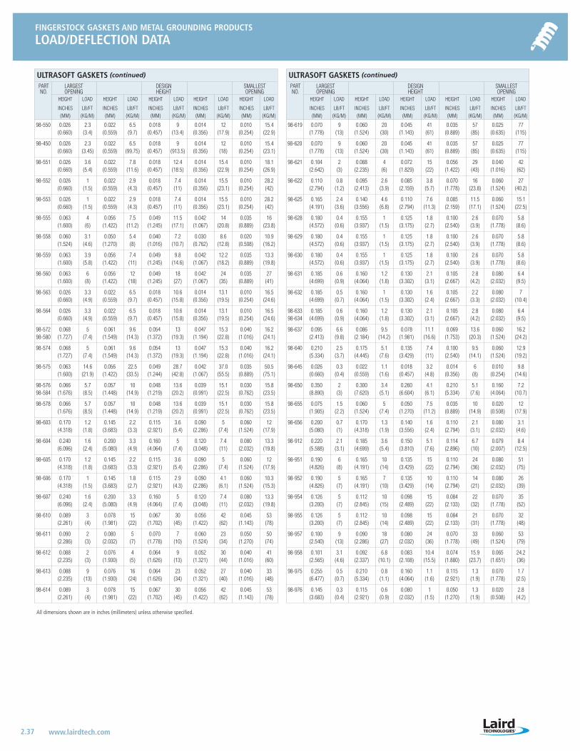
FINGERSTOCK GASKETS AND METAL GROUNDING PRODUCTS
LOAD/DEFLECTION DATA
2.37 www.lairdtech.com
All dimensions shown are in inches (millimeters) unless otherwise specified.
ULTRASOFT GASKETS (continued)
PART LARGEST DESIGN SMALLEST NO. OPENING HEIGHT OPENING
HEIGHT LOAD HEIGHT LOAD HEIGHT LOAD HEIGHT LOAD HEIGHT LOAD
INCHES LB/FT INCHES LB/FT INCHES LB/FT INCHES LB/FT INCHES LB/FT(MM) (KG/M) (MM) (KG/M) (MM) (KG/M) (MM) (KG/M) (MM) (KG/M)
98-550 0.026 2.3 0.022 6.5 0.018 9 0.014 12 0.010 15.4(0.660) (3.4) (0.559) (9.7) (0.457) (13.4) (0.356) (17.9) (0.254) (22.9)
98-450 0.026 2.3 0.022 6.5 0.018 9 0.014 12 0.010 15.4(0.660) (3.45) (0.559) (99.75) (0.457) (913.5) (0.356) (18) (0.254) (23.1)
98-551 0.026 3.6 0.022 7.8 0.018 12.4 0.014 15.4 0.010 18.1(0.660) (5.4) (0.559) (11.6) (0.457) (18.5) (0.356) (22.9) (0.254) (26.9)
98-552 0.026 1 0.022 2.9 0.018 7.4 0.014 15.5 0.010 28.2(0.660) (1.5) (0.559) (4.3) (0.457) (11) (0.356) (23.1) (0.254) (42)
98-553 0.026 1 0.022 2.9 0.018 7.4 0.014 15.5 0.010 28.2(0.660) (1.5) (0.559) (4.3) (0.457) (11) (0.356) (23.1) (0.254) (42)
98-555 0.063 4 0.056 7.5 0.049 11.5 0.042 14 0.035 16(1.600) (6) (1.422) (11.2) (1.245) (17.1) (1.067) (20.8) (0.889) (23.8)
98-558 0.060 3.1 0.050 5.4 0.040 7.2 0.030 8.6 0.020 10.9(1.524) (4.6) (1.270) (8) (1.016) (10.7) (0.762) (12.8) (0.508) (16.2)
98-559 0.063 3.9 0.056 7.4 0.049 9.8 0.042 12.2 0.035 13.3(1.600) (5.8) (1.422) (11) (1.245) (14.6) (1.067) (18.2) (0.889) (19.8)
98-560 0.063 6 0.056 12 0.049 18 0.042 24 0.035 27(1.600) (8) (1.422) (18) (1.245) (27) (1.067) (35) (0.889) (41)
98-563 0.026 3.3 0.022 6.5 0.018 10.6 0.014 13.1 0.010 16.5(0.660) (4.9) (0.559) (9.7) (0.457) (15.8) (0.356) (19.5) (0.254) (24.6)
98-564 0.026 3.3 0.022 6.5 0.018 10.6 0.014 13.1 0.010 16.5(0.660) (4.9) (0.559) (9.7) (0.457) (15.8) (0.356) (19.5) (0.254) (24.6)
98-572 0.068 5 0.061 9.6 0.054 13 0.047 15.3 0.040 16.298-580 (1.727) (7.4) (1.549) (14.3) (1.372) (19.3) (1.194) (22.8) (1.016) (24.1)
98-574 0.068 5 0.061 9.6 0.054 13 0.047 15.3 0.040 16.2(1.727) (7.4) (1.549) (14.3) (1.372) (19.3) (1.194) (22.8) (1.016) (24.1)
98-575 0.063 14.6 0.056 22.5 0.049 28.7 0.042 37.0 0.035 50.5(1.600) (21.9) (1.422) (33.5) (1.244) (42.8) (1.067) (55.5) (0.889) (75.1)
98-576 0.066 5.7 0.057 10 0.048 13.6 0.039 15.1 0.030 15.898-584 (1.676) (8.5) (1.448) (14.9) (1.219) (20.2) (0.991) (22.5) (0.762) (23.5)
98-578 0.066 5.7 0.057 10 0.048 13.6 0.039 15.1 0.030 15.8(1.676) (8.5) (1.448) (14.9) (1.219) (20.2) (0.991) (22.5) (0.762) (23.5)
98-603 0.170 1.2 0.145 2.2 0.115 3.6 0.090 5 0.060 12(4.318) (1.8) (3.683) (3.3) (2.921) (5.4) (2.286) (7.4) (1.524) (17.9)
98-604 0.240 1.6 0.200 3.3 0.160 5 0.120 7.4 0.080 13.3(6.096) (2.4) (5.080) (4.9) (4.064) (7.4) (3.048) (11) (2.032) (19.8)
98-605 0.170 1.2 0.145 2.2 0.115 3.6 0.090 5 0.060 12(4.318) (1.8) (3.683) (3.3) (2.921) (5.4) (2.286) (7.4) (1.524) (17.9)
98-606 0.170 1 0.145 1.8 0.115 2.9 0.090 4.1 0.060 10.3(4.318) (1.5) (3.683) (2.7) (2.921) (4.3) (2.286) (6.1) (1.524) (15.3)
98-607 0.240 1.6 0.200 3.3 0.160 5 0.120 7.4 0.080 13.3(6.096) (2.4) (5.080) (4.9) (4.064) (7.4) (3.048) (11) (2.032) (19.8)
98-610 0.089 3 0.078 15 0.067 30 0.056 42 0.045 53(2.261) (4) (1.981) (22) (1.702) (45) (1.422) (62) (1.143) (78)
98-611 0.090 2 0.080 5 0.070 7 0.060 23 0.050 50(2.286) (3) (2.032) (7) (1.778) (10) (1.524) (34) (1.270) (74)
98-612 0.088 2 0.076 4 0.064 9 0.052 30 0.040 41(2.235) (3) (1.930) (5) (1.626) (13) (1.321) (44) (1.016) (60)
98-613 0.088 9 0.076 16 0.064 23 0.052 27 0.040 33(2.235) (13) (1.930) (24) (1.626) (34) (1.321) (40) (1.016) (48)
98-614 0.089 3 0.078 15 0.067 30 0.056 42 0.045 53(2.261) (4) (1.981) (22) (1.702) (45) (1.422) (62) (1.143) (78)
ULTRASOFT GASKETS (continued)
PART LARGEST DESIGN SMALLEST NO. OPENING HEIGHT OPENING
HEIGHT LOAD HEIGHT LOAD HEIGHT LOAD HEIGHT LOAD HEIGHT LOAD
INCHES LB/FT INCHES LB/FT INCHES LB/FT INCHES LB/FT INCHES LB/FT(MM) (KG/M) (MM) (KG/M) (MM) (KG/M) (MM) (KG/M) (MM) (KG/M)
98-619 0.070 9 0.060 20 0.045 41 0.035 57 0.025 77(1.778) (13) (1.524) (30) (1.143) (61) (0.889) (85) (0.635) (115)
98-620 0.070 9 0.060 20 0.045 41 0.035 57 0.025 77(1.778) (13) (1.524) (30) (1.143) (61) (0.889) (85) (0.635) (115)
98-621 0.104 2 0.088 4 0.072 15 0.056 29 0.040 42(2.642) (3) (2.235) (6) (1.829) (22) (1.422) (43) (1.016) (62)
98-622 0.110 0.8 0.095 2.6 0.085 3.8 0.070 16 0.060 27(2.794) (1.2) (2.413) (3.9) (2.159) (5.7) (1.778) (23.8) (1.524) (40.2)
98-625 0.165 2.4 0.140 4.6 0.110 7.6 0.085 11.5 0.060 15.1(4.191) (3.6) (3.556) (6.8) (2.794) (11.3) (2.159) (17.1) (1.524) (22.5)
98-628 0.180 0.4 0.155 1 0.125 1.8 0.100 2.6 0.070 5.8(4.572) (0.6) (3.937) (1.5) (3.175) (2.7) (2.540) (3.9) (1.778) (8.6)
98-629 0.180 0.4 0.155 1 0.125 1.8 0.100 2.6 0.070 5.8(4.572) (0.6) (3.937) (1.5) (3.175) (2.7) (2.540) (3.9) (1.778) (8.6)
98-630 0.180 0.4 0.155 1 0.125 1.8 0.100 2.6 0.070 5.8(4.572) (0.6) (3.937) (1.5) (3.175) (2.7) (2.540) (3.9) (1.778) (8.6)
98-631 0.185 0.6 0.160 1.2 0.130 2.1 0.105 2.8 0.080 6.4(4.699) (0.9) (4.064) (1.8) (3.302) (3.1) (2.667) (4.2) (2.032) (9.5)
98-632 0.185 0.5 0.160 1 0.130 1.6 0.105 2.2 0.080 7(4.699) (0.7) (4.064) (1.5) (3.302) (2.4) (2.667) (3.3) (2.032) (10.4)
98-633 0.185 0.6 0.160 1.2 0.130 2.1 0.105 2.8 0.080 6.498-634 (4.699) (0.9) (4.064) (1.8) (3.302) (3.1) (2.667) (4.2) (2.032) (9.5)
98-637 0.095 6.6 0.086 9.5 0.078 11.1 0.069 13.6 0.060 16.2(2.413) (9.8) (2.184) (14.2) (1.981) (16.6) (1.753) (20.3) (1.524) (24.2)
98-640 0.210 2.5 0.175 5.1 0.135 7.4 0.100 9.5 0.060 12.9(5.334) (3.7) (4.445) (7.6) (3.429) (11) (2.540) (14.1) (1.524) (19.2)
98-645 0.026 0.3 0.022 1.1 0.018 3.2 0.014 6 0.010 9.8(0.660) (0.4) (0.559) (1.6) (0.457) (4.8) (0.356) (8) (0.254) (14.6)
98-650 0.350 2 0.300 3.4 0.260 4.1 0.210 5.1 0.160 7.2(8.890) (3) (7.620) (5.1) (6.604) (6.1) (5.334) (7.6) (4.064) (10.7)
98-655 0.075 1.5 0.060 5 0.050 7.5 0.035 10 0.020 12(1.905) (2.2) (1.524) (7.4) (1.270) (11.2) (0.889) (14.9) (0.508) (17.9)
98-656 0.200 0.7 0.170 1.3 0.140 1.6 0.110 2.1 0.080 3.1(5.080) (1) (4.318) (1.9) (3.556) (2.4) (2.794) (3.1) (2.032) (4.6)
98-912 0.220 2.1 0.185 3.6 0.150 5.1 0.114 6.7 0.079 8.4(5.588) (3.1) (4.699) (5.4) (3.810) (7.6) (2.896) (10) (2.007) (12.5)
98-951 0.190 6 0.165 10 0.135 15 0.110 24 0.080 51(4.826) (8) (4.191) (14) (3.429) (22) (2.794) (36) (2.032) (75)
98-952 0.190 5 0.165 7 0.135 10 0.110 14 0.080 26(4.826) (7) (4.191) (10) (3.429) (14) (2.794) (21) (2.032) (39)
98-954 0.126 5 0.112 10 0.098 15 0.084 22 0.070 35(3.200) (7) (2.845) (15) (2.489) (22) (2.133) (32) (1.778) (52)
98-955 0.126 5 0.112 10 0.098 15 0.084 21 0.070 32(3.200) (7) (2.845) (14) (2.489) (22) (2.133) (31) (1.778) (48)
98-957 0.100 9 0.090 18 0.080 24 0.070 33 0.060 53(2.540) (13) (2.286) (27) (2.032) (36) (1.778) (49) (1.524) (79)
98-958 0.101 3.1 0.092 6.8 0.083 10.4 0.074 15.9 0.065 24.2(2.565) (4.6) (2.337) (10.1) (2.108) (15.5) (1.880) (23.7) (1.651) (36)
98-975 0.255 0.5 0.210 0.8 0.160 1.1 0.115 1.3 0.070 1.7(6.477) (0.7) (5.334) (1.1) (4.064) (1.6) (2.921) (1.9) (1.778) (2.5)
98-976 0.145 0.3 0.115 0.6 0.080 1 0.050 1.3 0.020 2.8(3.683) (0.4) (2.921) (0.9) (2.032) (1.5) (1.270) (1.9) (0.508) (4.2)
LT-3034 Metals_catalog 10/8/04 10:31 AM Page 2.37
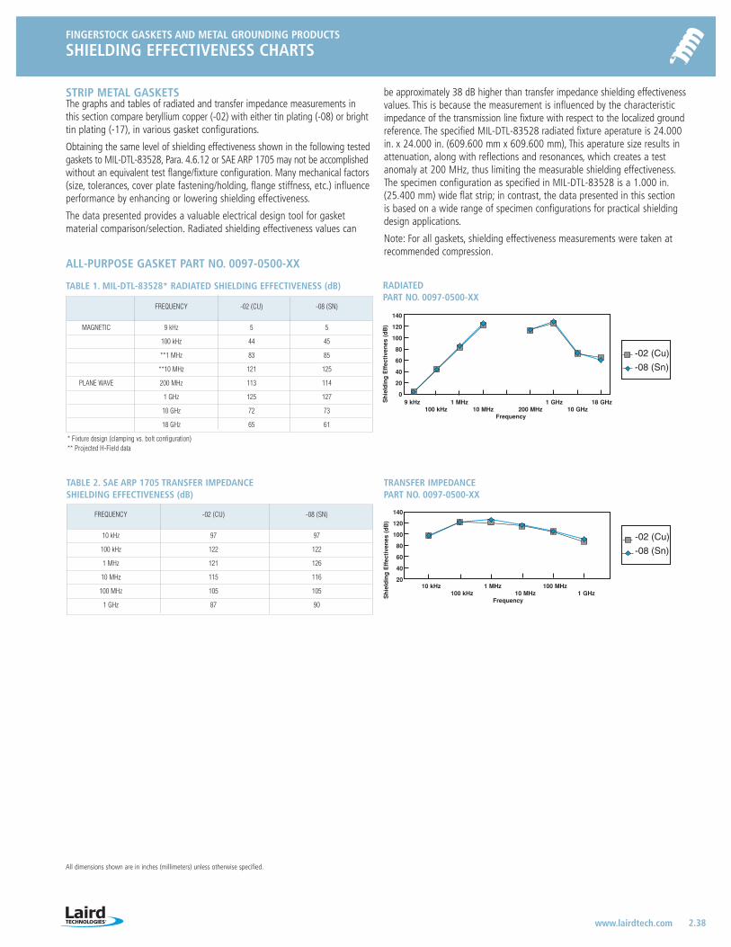
FINGERSTOCK GASKETS AND METAL GROUNDING PRODUCTS
SHIELDING EFFECTIVENESS CHARTS
2.38 www.lairdtech.com
All dimensions shown are in inches (millimeters) unless otherwise specified.
-02 (Cu)
-08 (Sn)
Sh
ield
ing
Eff
ecti
ven
es (
dB
)
140
120
100
80
60
40
20
09 kHz 1 MHz 1 GHz 18 GHz
100 kHz 10 MHz 200 MHz 10 GHzFrequency
RADIATED PART NO. 0097-0500-XX
-02 (Cu)
-08 (Sn)
Sh
ield
ing
Eff
ecti
ven
es (
dB
)
140
120
100
80
60
40
2010 kHz 1 MHz 100 MHz
100 kHz 10 MHz 1 GHzFrequency
TRANSFER IMPEDANCE PART NO. 0097-0500-XX
ALL-PURPOSE GASKET PART NO. 0097-0500-XX
TABLE 1. MIL-DTL-83528* RADIATED SHIELDING EFFECTIVENESS (dB)
* Fixture design (clamping vs. bolt configuration)** Projected H-Field data
STRIP METAL GASKETSThe graphs and tables of radiated and transfer impedance measurements inthis section compare beryllium copper (-02) with either tin plating (-08) or brighttin plating (-17), in various gasket configurations.
Obtaining the same level of shielding effectiveness shown in the following testedgaskets to MIL-DTL-83528, Para. 4.6.12 or SAE ARP 1705 may not be accomplishedwithout an equivalent test flange/fixture configuration. Many mechanical factors(size, tolerances, cover plate fastening/holding, flange stiffness, etc.) influenceperformance by enhancing or lowering shielding effectiveness.
The data presented provides a valuable electrical design tool for gasketmaterial comparison/selection. Radiated shielding effectiveness values can
be approximately 38 dB higher than transfer impedance shielding effectivenessvalues. This is because the measurement is influenced by the characteristicimpedance of the transmission line fixture with respect to the localized groundreference. The specified MIL-DTL-83528 radiated fixture aperature is 24.000in. x 24.000 in. (609.600 mm x 609.600 mm), This aperature size results inattenuation, along with reflections and resonances, which creates a testanomaly at 200 MHz, thus limiting the measurable shielding effectiveness.The specimen configuration as specified in MIL-DTL-83528 is a 1.000 in.(25.400 mm) wide flat strip; in contrast, the data presented in this section is based on a wide range of specimen configurations for practical shieldingdesign applications.
Note: For all gaskets, shielding effectiveness measurements were taken atrecommended compression.
FREQUENCY -02 (CU) -08 (SN)
MAGNETIC 9 kHz 5 5
100 kHz 44 45
**1 MHz 83 85
**10 MHz 121 125
PLANE WAVE 200 MHz 113 114
1 GHz 125 127
10 GHz 72 73
18 GHz 65 61
TABLE 2. SAE ARP 1705 TRANSFER IMPEDANCESHIELDING EFFECTIVENESS (dB)
FREQUENCY -02 (CU) -08 (SN)
10 kHz 97 97
100 kHz 122 122
1 MHz 121 126
10 MHz 115 116
100 MHz 105 105
1 GHz 87 90
LT-3034 Metals_catalog 10/8/04 10:31 AM Page 2.38
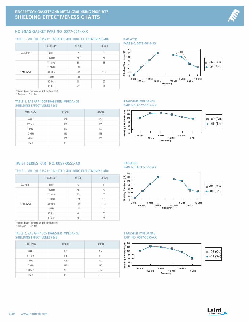
FINGERSTOCK GASKETS AND METAL GROUNDING PRODUCTS
SHIELDING EFFECTIVENESS CHARTS
2.39 www.lairdtech.com
-02 (Cu)
-08 (Sn)
Sh
ield
ing
Eff
ecti
ven
es (
dB
) 140
120
100
80
60
40
20
09 kHz 1 MHz 1 GHz 18 GHz
100 kHz 10 MHz 200 MHz 10 GHzFrequency
RADIATED PART NO. 0077-0014-XX
-02 (Cu)
-08 (Sn)S
hie
ldin
g E
ffec
tive
nes
(d
B) 140
120
100
80
60
40
2010 kHz 1 MHz 100 MHz
100 kHz 10 MHz 1 GHzFrequency
TRANSFER IMPEDANCE PART NO. 0077-0014-XX
-02 (Cu)
-08 (Sn)
Sh
ield
ing
Eff
ecti
ven
es (
dB
)
140
120
100
80
60
40
20
09 kHz 1 MHz 1 GHz 18 GHz
100 kHz 10 MHz 200 MHz 10 GHzFrequency
RADIATED PART NO. 0097-0555-XX
-02 (Cu)
-08 (Sn)
Sh
ield
ing
Eff
ecti
ven
es (
dB
)
140
120
100
80
60
40
2010 kHz 1 MHz 100 MHz
100 kHz 10 MHz 1 GHzFrequency
TRANSFER IMPEDANCE PART NO. 0097-0555-XX
NO SNAG GASKET PART NO. 0077-0014-XX
TABLE 1. MIL-DTL-83528* RADIATED SHIELDING EFFECTIVENESS (dB)
* Fixture design (clamping vs. bolt configuration)** Projected H-Field data
FREQUENCY -02 (CU) -08 (SN)
MAGNETIC 9 kHz 7 7
100 kHz 46 45
**1 MHz 85 83
**10 MHz 123 121
PLANE WAVE 200 MHz 114 114
1 GHz 128 101
10 GHz 65 65
18 GHz 47 44
TABLE 2. SAE ARP 1705 TRANSFER IMPEDANCESHIELDING EFFECTIVENESS (dB)
FREQUENCY -02 (CU) -08 (SN)
10 kHz 102 101
100 kHz 126 125
1 MHz 130 129
10 MHz 119 118
100 MHz 107 106
1 GHz 94 97
TWIST SERIES PART NO. 0097-0555-XX
TABLE 1. MIL-DTL-83528* RADIATED SHIELDING EFFECTIVENESS (dB)
* Fixture design (clamping vs. bolt configuration)** Projected H-Field data
FREQUENCY -02 (CU) -08 (SN)
MAGNETIC 9 kHz 13 13
100 kHz 49 49
**1 MHz 85 85
**10 MHz 121 121
PLANE WAVE 200 MHz 115 114
1 GHz 102 101
10 GHz 48 56
18 GHz 48 44
TABLE 2. SAE ARP 1705 TRANSFER IMPEDANCESHIELDING EFFECTIVENESS (dB)
FREQUENCY -02 (CU) -08 (SN)
10 kHz 102 102
100 kHz 124 123
1 MHz 121 120
10 MHz 113 110
100 MHz 96 95
1 GHz 59 61
LT-3034 Metals_catalog 10/8/04 10:31 AM Page 2.39
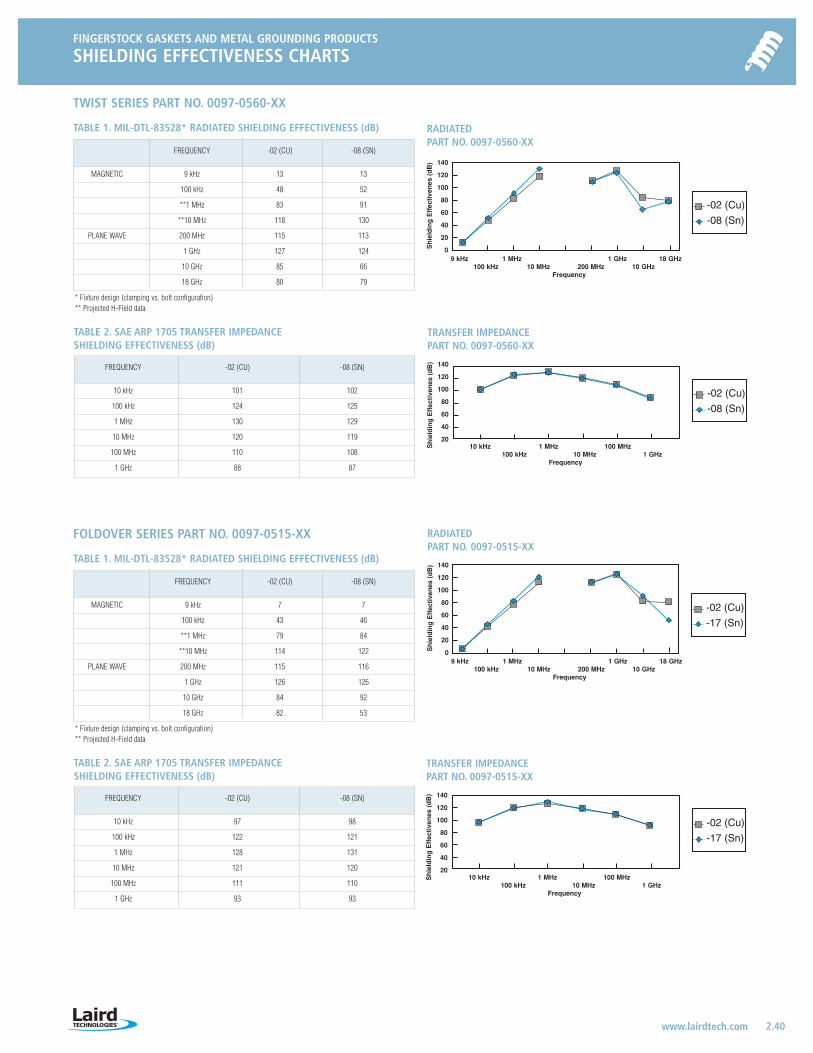
FINGERSTOCK GASKETS AND METAL GROUNDING PRODUCTS
SHIELDING EFFECTIVENESS CHARTS
2.40 www.lairdtech.com
TWIST SERIES PART NO. 0097-0560-XX
TABLE 1. MIL-DTL-83528* RADIATED SHIELDING EFFECTIVENESS (dB)
* Fixture design (clamping vs. bolt configuration)** Projected H-Field data
FREQUENCY -02 (CU) -08 (SN)
MAGNETIC 9 kHz 13 13
100 kHz 48 52
**1 MHz 83 91
**10 MHz 118 130
PLANE WAVE 200 MHz 115 113
1 GHz 127 124
10 GHz 85 66
18 GHz 80 79
TABLE 2. SAE ARP 1705 TRANSFER IMPEDANCESHIELDING EFFECTIVENESS (dB)
FREQUENCY -02 (CU) -08 (SN)
10 kHz 101 102
100 kHz 124 125
1 MHz 130 129
10 MHz 120 119
100 MHz 110 108
1 GHz 88 87
FOLDOVER SERIES PART NO. 0097-0515-XX
TABLE 1. MIL-DTL-83528* RADIATED SHIELDING EFFECTIVENESS (dB)
* Fixture design (clamping vs. bolt configuration)** Projected H-Field data
FREQUENCY -02 (CU) -08 (SN)
MAGNETIC 9 kHz 7 7
100 kHz 43 46
**1 MHz 79 84
**10 MHz 114 122
PLANE WAVE 200 MHz 115 116
1 GHz 126 126
10 GHz 84 92
18 GHz 82 53
TABLE 2. SAE ARP 1705 TRANSFER IMPEDANCESHIELDING EFFECTIVENESS (dB)
FREQUENCY -02 (CU) -08 (SN)
10 kHz 97 98
100 kHz 122 121
1 MHz 128 131
10 MHz 121 120
100 MHz 111 110
1 GHz 93 93
-02 (Cu)
-08 (Sn)
Sh
ield
ing
Eff
ecti
ven
es (
dB
) 140
120
100
80
60
40
20
09 kHz 1 MHz 1 GHz 18 GHz
100 kHz 10 MHz 200 MHz 10 GHzFrequency
RADIATED PART NO. 0097-0560-XX
-02 (Cu)
-08 (Sn)
Sh
ield
ing
Eff
ecti
ven
es (
dB
) 140
120
100
80
60
40
2010 kHz 1 MHz 100 MHz
100 kHz 10 MHz 1 GHzFrequency
TRANSFER IMPEDANCE PART NO. 0097-0560-XX
-02 (Cu)
-17 (Sn)
Sh
ield
ing
Eff
ecti
ven
es (
dB
) 140
120
100
80
60
40
20
09 kHz 1 MHz 1 GHz 18 GHz
100 kHz 10 MHz 200 MHz 10 GHzFrequency
RADIATED PART NO. 0097-0515-XX
-02 (Cu)
-17 (Sn)
Sh
ield
ing
Eff
ecti
ven
es (
dB
) 140
120
100
80
60
40
2010 kHz 1 MHz 100 MHz
100 kHz 10 MHz 1 GHzFrequency
TRANSFER IMPEDANCE PART NO. 0097-0515-XX
LT-3034 Metals_catalog 10/8/04 10:31 AM Page 2.40