Embed Size (px)
Citation preview
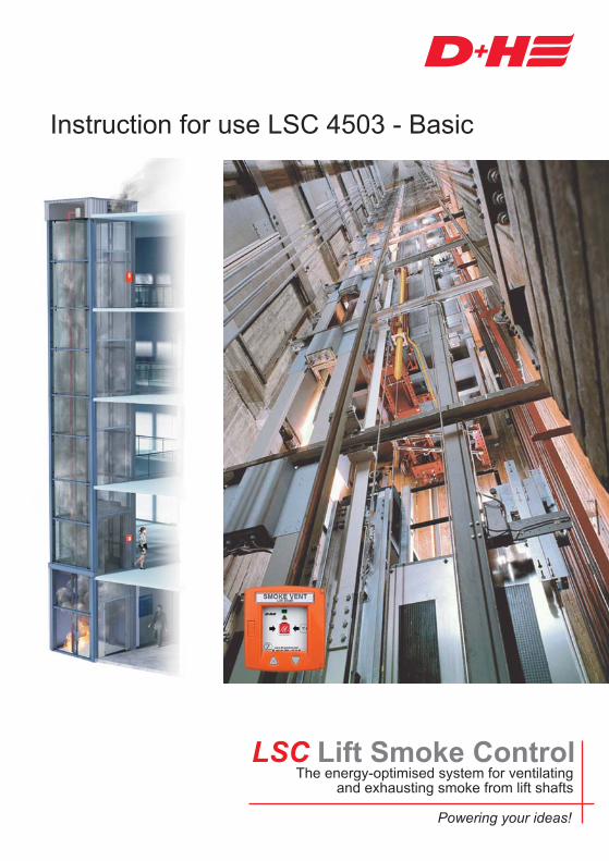
LSC Lift Smoke ControlThe energy-optimised system for ventilating
and exhausting smoke from lift shafts
Instruction for use LSC 4503 - Basic
SMOKE VENTLift Shaft
Powering your ideas!
Index
99.830.00 3.1/09/112/60 LSC-Basic
1.0 ........................................................................................4
2.0 .........................................................................7
3.0 System overview................................................................................................9
4.0 .....................................................................................................14
Lift Shaft Smoke Vent
Introduction to SHEV systems
Tube system
1.1 Legal aspects ...........................................................................................................................41.2 One system many advantages.................................................................................................51.3 Solutions for every case of application.....................................................................................6
2.1 Details to the product ...............................................................................................................72.2 Details about mounting.............................................................................................................72.3 Safety notes .............................................................................................................................72.4 Maintenance.............................................................................................................................82.5 Guarantee ................................................................................................................................8
3.1 Functional principle ................................................................................................................103.2 Why smoke suction? ..............................................................................................................113.3 Cable for D+H smoke and heat vent systems........................................................................123.4 Line lenghts and cross sections .............................................................................................123.5 Project planning of smoke suction system .............................................................................13
4.1 Mounting of tube system ........................................................................................................154.2 Mounting of reflux valve at suction tube end ..........................................................................164.3 Pipe clamps............................................................................................................................174.4 Checking of tube system........................................................................................................174.5 Suction openings....................................................................................................................184.6 Air filter LF-AD........................................................................................................................194.7 Free-blowing device ...............................................................................................................204.8 Titanus pipe-clean ..................................................................................................................20
5.1 Smoke extraction system, intake direction .............................................................................225.2 Smoke extraction system attachment ....................................................................................235.3 Plug-and-play commissioning ................................................................................................245.4 Commissioning using the DIAG 3 diagnostic tool ..................................................................25
5.0 Micro-Sens smoke extraction system ...........................................................21
English
3/6099.830.00 3.1/09/11 LSC-Basic
Index
6.0 LSC 4503 control system 26
7.0 Demand-optimized ventilation........................................................................36
8.0 Smoke vent button RT 45-H............................................................................44
6.1 Brief description of the LSC 4503 266.2 LSC 4503 installation location 266.3 Wiring plan .............................................................................................................................276.4 SHEV Type LSC 4503 control panel (Technical Data) ...........................................................286.5 Control panel, inside view ......................................................................................................296.6 Control panel installation ...................................................................................................30/316.7 RT 45 trigger button installation..............................................................................................326.8 LSC 4503 operation ..........................................................................................................33/346.9 Emergency closing .................................................................................................................35
7.1 View of main PCB ..................................................................................................................377.2 LSC 4503 functional description........................................................................................38/397.3 Factory setting DIP-switch......................................................................................................397.4 Control panel coding .........................................................................................................40/417.5 Line switch-off ........................................................................................................................417.6 Information for starting ...........................................................................................................427.7 Examination............................................................................................................................43
8.1 Connection SHEV button .......................................................................................................458.2 Connection of lift and external messages ..............................................................................468.3 Connection of smoke extraction system ...........................................................478.4 Connection MOT ....................................................................................................................488.5 Connection vent button LT + SLT 42 ......................................................................................498.6 Connection temperature control RTR 230..............................................................................508.7 Connection alarm siren B/SE 24 ............................................................................................508.8 Connection flashing light BL 41..............................................................................................508.9 Connection Co2 sensor..........................................................................................................518.10 Connection wind-rain-sensor WRG 82...................................................................................518.11 Connection of PCB KM 45 LSC .............................................................................................528.12 KM 45 LSC connection overview ...........................................................................................53
9.1 Louvre drive............................................................................................................................549.2 Domelight ...............................................................................................................................559.3 Informations for mounting of louvre / domelight .....................................................................56
Micro Sens®
9.0 Smoke vent device / Connecting elements .................................................................54
English
99.830.00 3.1/09/114/60 LSC-Basic English
1.0
1.1
Lift Shaft Smoke Vent
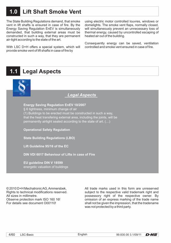
The State Building Regulations demand, that smokevent in lift shafts is ensured in case of fire. By theEnergy Saving Regulation EnEV is simultaneouslydemanded, that building external areas must beconstructed in such a way, that they are permanentair-tight according to the state of the art.
With LSC D+H offers a special system, which willprovide smoke vent of lift shafts in case of fire by
© 2010 D+H MechatronicAG,Ammersbek,Rights to technical modifications reserved.All sizes in millimetre.Observe protection mark ISO 160 16!For details see document O00110!
All trade marks used in this form are unreservedsubject to the respective valid trademark right andpossessory right of the respective owner. Byomission of an express marking of the trade nameshall not be given the impression, that the tradenamewas not protected by a third party.
Energy Saving Regulation EnEV 10/2007
Operational Safety Regulation
State Building Regulations (LBO)
Lift Guideline 95/16 of the EC
DIN VDI 6017 Behaviour of Lifts in case of Fire
EU guideline DIN V 18599
§ 6 tightness, minimum change of air(1) Buildings to be erected must be constructed in such a way,that the heat transfering external area, including the joints, will bepermanently airtight sealed according to the state of art. (…)
energetic valuation of buildings
Legal Aspects
Legal Aspects
using electric motor controlled louvres, windows ordomelights. The smoke vent flaps, normally closed,will simultaneously prevent an unnecessary loss ofthermal energy, caused by uncontrolled escaping ofheated air out of the building.
Consequently energy can be saved, ventilationcontrolled and smoke vent ensured in case of fire.
5/6099.830.00 3.1/09/11 LSC-BasicEnglish
1.2 One System many Advantages
LSC - Lift Control is an energy-optimized systemfor smoke vent and ventilation of lift shafts.
Less draught in a staircase
Early Evacuation
The closed smoke vent openings will lessen thedraught in the staircase and thereby the thermalcomfort will be improved for the user.
Possible whistling sounds will be additionallyavoided, caused by a too high flow of air.
A fire will be already recognized during a fireformation through the smoke suction system used.People in the lift can be moved earlier therefore tothe smokefree evacuating level.
Lower Thermal Energy Costs
Better Building-Energy Pass
Operators and users must rethink their attitudetowards energy consumption forced by thecontinous high oil price as well as generallyincreasing energy costs.
The D+H system LSC avoids unnecessary losses ofenergy, because a permanent opening in the top endarea of the lift shaft is avoided and with this, anuncontrolled ventilation of the building will beprevented.
The result:Operating expenses will be noticeably reduced.
An optimized thermal insulation will lead as well tobetter values in the building-energy pass, which willbe successively prepared from 2007 for all buildings.
This will have a positive effect on the image of abuilding.
From this will result better rentability, not leastbecause of lower additional costs. This will have apositive influence on the building value as well.
Using , the central control panel may bemounted on the next to the lift door. ASHEV trigger and integrated vent button is alreadyintegrated in the control centre.
may be used when the main evacuationlevel is monitored on-site or not at all. The shaft headmay optionally be monitored for overheating using aroom temperature controller.Ideally, the smoke extraction system should beinstalled in the lift machine room. If this is notpossible, a suitable location should be agreed on-site.
LSC-Basicground floor
LSC-Basic
The System is designed specifically forlift shafts with a height of 20 meters.Particular attention has been paid to investmentconsiderations. has a very shortamortization time.
LSC-Basic
LSC-Basic
Controlled ventilationThe smoke vent is individually controlled byappropr iate sensors for vent i la t ion andcontrolled heat extraction.
A thermostat may optionally be installed tomonitor the temperature to ensure a constantpleasant indoor climate while preventing liftoverheating without a machine room. An airquality (CO2) sensor may also be used.In addition to the automatic function, manualventilation is also possible for air change everyfive hours.
99.830.00 3.1/09/116/60 LSC-Basic English
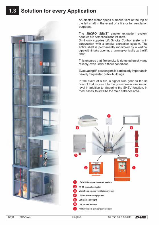
1.3 Solution for every Application
LSS dome skylight
LSL louver window
RTR 231 room temperature control
LSP 44 extraction pipe set
LSC 4503 compact control system
RT 45 manual activator
MicroSens smoke ventilation system
An electric motor opens a smoke vent at the top ofthe left shaft in the event of a fire or for ventilationpurposes.
The smoke extraction systemhandles fire detection in the lift shaft.D+H only supplies Lift Smoke Control systems inconjunction with a smoke extraction system. Theentire shaft is permanently monitored by a verticalpipe with intake openings running vertically up the liftshaft.
This ensures that fire smoke is detected quickly andreliably, even under difficult conditions.
Evacuating lift passengers is particularly important inheavily frequented public buildings.
In the event of a fire, a signal also goes to the liftcontrol that moves it to the preset main evacuationlevel in addition to triggering the SHEV function. Inmost cases, this will be the main entrance area.
MICRO SENS®
SMOKE VENTLift Shaft
SMOKE VENTLift Shaft
7/6099.830.00 3.1/09/11 LSC-BasicEnglish
2.0
2.2
2.1
2.3
Safety system for protecting human life andmaterial assets! Once a year functional testingby a specialist company authorized by themanufacturer.Connection, mounting and functional testing by aspecialist company authorized by the manufacturer.Green control diodes in the buttons must constantlylighten, otherwise see “Informations for Starting”.Repair power failure at once. Instructions of the fireprotection authorities must be always observed.
This SHEV-system has been constructed inaccordance with the latest state of the art andscience. In case of professional mounting andmaintenance it is of high operating safety.Nevertheless, there can dangers arise from theproduct, if by unqualified personell used inexpertly ornot in accordance with the regulations.
Introduction to SHEV Systems
Details about Mounting
Details to the Product
Safety Notes
Danger of Injury or Life!central appliance
switched idleWorking on the is only allowed, ifthis is . This includes distributionvoltage with 230 VAC alternating voltage as well asemergency power supply with 24 VDC directvoltage. Only electrical specialist companies areauthorized to install these systems, who haveelectrical specialist staff with relevant experiences ininstalling danger alarm systems or smoke and heatvent systems. Only these ones can take onresponsibility for functioning, and can ensureproduct liability for the whole system (see productliability law BGBL.I S.2198 and BGB (bodily injury,compensation for damage). Therfore, regularmaintenance and checking of functional readiness isimperative and has to be ensured.
Smoke and heat vent systems (SHEVs) are veryimportant elements of structural preventive fireprotection.
Smoke and heat vent systems are appliances ofpreventive fire protection. They fulfil importantfunctions in case of fire as there are: protection ofhuman life by creating a smokefree layer, by which
escape and rescue routes will be kept free for the firebrigade. Consequential damages by conflagrationgases are reduced and therefore considerablematerial assets are often protected from destruction.Precondition for this is, that the system will functionabsolutely reliable in a case of fire.
These standard requirements are demandedaccording to regulations of the DIN, of theAssociation of German Insurer against damage ofproperty (VdS) and the respective local authorities.In spite of greatest possible care we can not acceptresponsibility for this document. All informationsgiven are no warranted qualification in the sense of§ 434 BGB.Current directions of the authorities and the VDE-regulations must be taken into account during theentire mounting and installation of the system.Regulations of the local EVU must be additionallyobserved. Furthermore, individual working stepsmust be coordinated with the management of works.
Should special problems arise during mounting oroperation, with which is not extensively enough dealtwith in the operating instructions, so please for yourown safety do not hesitate to consult with themanufacturer.Apart from suction tubes with reflux valve and airrecirculation,
Acceptance through the TÜV can beonly obtained with this precondition as well as withsimple and economical maintenance warranted.
no components will be installed inthe lift shaft!
Unauthorized modifications and alterations at theSHEV-system are for safety reasons.This operating instruction must be
before installation.Keep to the instruction.
not allowedread through
carefully
Please observe in any case the safety notes.
99.830.00 3.1/09/118/60 LSC-Basic
2.5
2.4
Guarantee
Maintenance
Smoke and heat vent systems must be maintained atannual intervals by authorized specialist companiesaccording to DIN 18232 section 2 paragraph 10.2,and VDE 0833 section 1 paragraph 5.3.4 for alarmsystems and manufacturer guidelines.
Renew test badge, keep control book.The respective current D+H maintenance instructionis decisive.D+H authorized expert companies have beenspecially trained by D+H for carrying out expertly thismaintenance, and they get automatically the latestmaintenance instructions.
Following tests must be carried out in the course ofmaintenance:- Outside examination/ inspection of system
components- Measuring of insulation resistances- Checking of all relevant power supply units- Functional testing of connected system
components- Record of competent carrying-out of
maintenance, and designation accordingto directions
Once a year by a specialist company, who isauthorized by the appliance manufacturer.
- Cleaning the extraction pipe and replacing theextraction filter
The control panel will report an overduemaintenance after approx. 14–16 months.The yellow diode on the RT 45 will start to flash, andcan only be reset using a special software tool by aspecialist company authorized by the manufacturer.
Information
Only regular and professional maintenancewarrants the necessary and permanentfunctional safety.
D+H Mechatronic AG D+HMechatronic AG
D+HMechatronic AG
D+H Mechatronic AG
D+HMechatronic AG
Only authorized specialist companies are allowed toinstall and maintain smoke and heat vent systemsand system components, constructed anddistributed by . All
partners belong to theseauthorized specialist companies, who regularlyundergo an in-house training to ensure theirqualification and experience.
According to DIN VDE 0108 section 1 paragraph9.1.1 accumulators for emergency supply (leadaccumulators) must be checked every six months bya person, who has been introduced to this task, andonce a year, maintenance must be carried out byspecialist companies.Accumulator types, which are used for
smoke and heat vent systemsmust be VdS approved, and must be released by
to use in smoke and heat ventsystems.
According to DIN 18232 section 2 paragraph 10.2the tests must be put down in an operational book,which the operator/ building owner must present tothe building supervision authority on request.This operational book is available at
(Ord.-No.: 68.700.15)Executed maintenance must be proved by a
maintenance/ and testingconfirmation.
Observe regulations for danger warning systemsVDE 0833, guidelines for electrical systems VdS2221, DIN 18232 for smoke and heat vent systems,regulations of the local fire-brigade and of EVU forconnection to mains supply.
D+HMechatronicAG
You will get guarantee for all D+H productsfrom date of verified handing over of the system up tomaximal 3 years after date of delivery, whenmounting and starting has been carried out by a D+Hauthorized .
2 years
distributor
D+H guarantee is expired, with connection of D+Hcomponents with external systems or with mixing ofD+H products with parts of other manufacturers.
English
9/6099.830.00 3.1/09/11 LSC-Basic
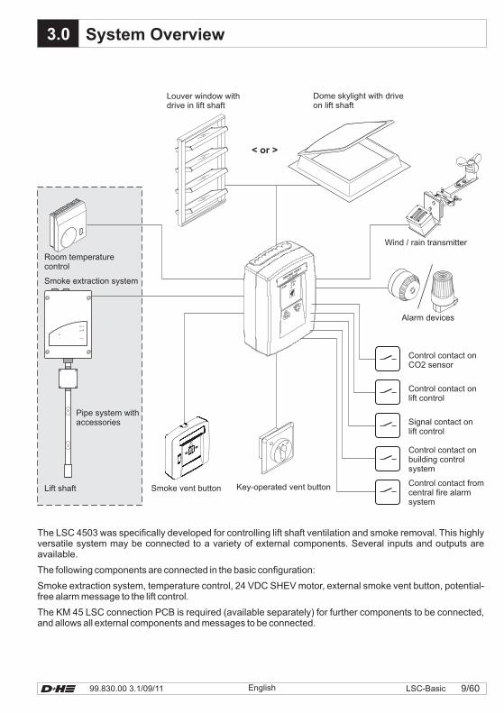
3.0 System Overview
English
Lift shaft Smoke vent button
Louver window withdrive in lift shaft
Dome skylight with driveon lift shaft
< or >
Alarm devices
Key-operated vent button
Control contact onCO2 sensor
Control contact onbuilding controlsystem
Control contact fromcentral fire alarmsystem
OK
Pipe system withaccessories
Wind / rain transmitter
I
0
Room temperaturecontrol
Smoke extraction system
Signal contact onlift control
Control contact onlift control
The LSC 4503 was specifically developed for controlling lift shaft ventilation and smoke removal. This highlyversatile system may be connected to a variety of external components. Several inputs and outputs areavailable.
The following components are connected in the basic configuration:
Smoke extraction system, temperature control, 24 VDC SHEV motor, external smoke vent button, potential-free alarm message to the lift control.
The KM 45 LSC connection PCB is required (available separately) for further components to be connected,and allows all external components and messages to be connected.
SMOKE VENT
LiftShaft
99.830.00 3.1/09/1110/60 LSC-Basic English
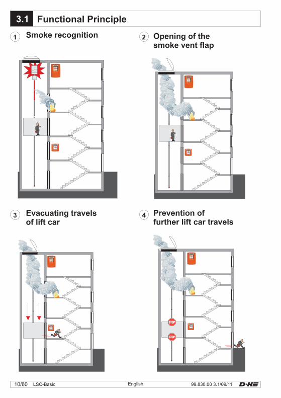
3.1 Functional Principle
1
3
Smoke recognition
Evacuating travelsof lift car
2
4
Opening of thesmoke vent flap
Prevention offurther lift car travels
11/6099.830.00 3.1/09/11 LSC-BasicEnglish
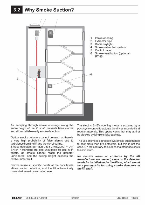
3.2 Why Smoke Suction?
Air sampling through intake openings along theentire height of the lift shaft prevents false alarmsand allows reliable early smoke detection.
Smoke intake at specific points at the floor levelsallows earlier detection, and the lift automaticallymoves to the main evacuation level.
Optical smoke detectors cannot be used, as there isa very high probability of false alarms due toturbulence from the lift and the risk of soiling.Smoke detectors per VDE 0833-2 (06/2009) + DINEN 54-7 standard are also unsuitable for use in liftshafts, as smoke cannot reach the detectorunhindered, and the ceiling height exceeds thetwelve-meter limit.
The electric SHEV opening motor is actuated by apost-cycle control to actuate the drives repeatedly atregular intervals. This opens vents that may at firstbe blocked by icing or sticky gaskets.
The use of smoke extraction systems is often thoughto cost more than fire detectors, but this is not thecase. On the contrary, this keeps maintenance coststo a minimum.
No control leads or contacts by the liftmanufacturer are needed, since no fire detectorneeds be installed under the lift car, which wouldbe a prerequisite for using smoke detectors inthe lift shaft.
2
1
6
1 Intake opening2 Extractor pipe3 Dome skylight4 Smoke extraction system5 Control panel6 Smoke vent button (optional)
RT 45
99.830.00 3.1/09/1112/60 LSC-Basic English
Cross section (mm²) =plain cable lenght (m) x total current
80
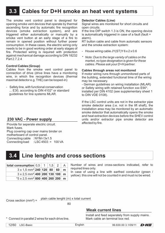
Line lenghts and cross sections
Cables for D+H smoke an heat vent systems
The smoke vent control panel is designed foropening smoke vent devices that operate by thermalascending force and by automatic fire recognitiondevices (smoke extraction system), and aretriggered either automatically or manually by asmoke vent button at an early stage of a fire toremain in opened position without further powerconsumption. In these cases, the electric wiring onlyneeds to be in good working order at early stages offire. Protected wiring is required with protectionagainst mechanical damage according to DIN 18232Part 2.7.2.4
-
Control Cables (Group)Cables from the smoke vent control panel toconnection of drive (drive lines have a monitoringwire, in which fire recognition devices (thermalmaximal detector e.g. THE) can be looped-in)
Safety line, with functional conservation... E30, according to DIN 4102* or standardguidelines for line systems MLAR.
Detector Cables (Line)
Cables through areas not monitored
Signal wires are monitored for short circuits andopen circuits.If the line DIP switch 1.3 is ON, the opening deviceis automatically triggered in case of a fault (fault =alarm).RT button cable and cable from automatic sensorsand the smoke extraction system:
- House wiring cable JY(ST)Y 6 x 2 x 0.6
* Note: Due to the large variety of cables on themarket, no type designation is given for thesecables. Please ask your D+H partner.
If motor wiring runs through unmonitored parts ofthe building, extended functional time of the wiringmay be necessary.- German guidelines on wiring installation (MLAR)or Safety wiring with retained function xxx E90*,installed per DIN 4102 (see supplementary sheet 1to DIN VDE 0108).
If the LSC control units are not in the extractor pipesmoke detector area (i.e. not in the lift shaft), theinstallation area may be monitored by an automaticsmoke detector that automatically opens the smokeand heat extraction devices before the SHEV controlunits and/or extractor pipe smoke detector areaffected by fire.
Number of wires and cross-sections indicated, refer torequired lines only.In case of using a line with earthed conductor (green /yellow). this one will not be counted in and must no be wired.
* Connect in parallel 2 wires for each drive line.Install and feed seperately from supply mains.Mark cable an terminal box red.
Weak current lines
Provide for seperate electric circuit.Mark fuses.Plug covering cap over mains binder onmotherboard of control panel.Connecting cable : NYM-I 3x1.5Connecting load : LSC 4503 = 100 VA
230 VAC - Power supply
3.3
3.4
total consumption
3 x 1,5 mm²
3 x 2,5 mm²
*5 x 2,5 mm²
0,5
240
400
800
1
120
200
400
1,5
80
130
260
2
60
100
200
A
m
m
m
13/6099.830.00 3.1/09/11 LSC-BasicEnglish
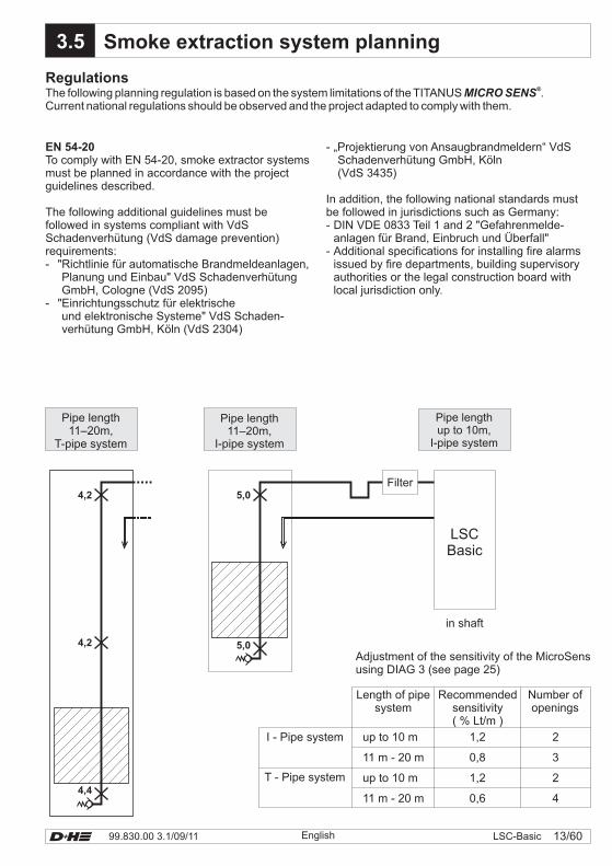
3.5 Smoke extraction system planning
RegulationsThe following planning regulation is based on the system limitations of the TITANUS .Current national regulations should be observed and the project adapted to comply with them.
MICRO SENS®
EN 54-20To comply with EN 54-20, smoke extractor systemsmust be planned in accordance with the projectguidelines described.
The following additional guidelines must befollowed in systems compliant with VdSSchadenverhütung (VdS damage prevention)requirements:- "Richtlinie für automatische Brandmeldeanlagen,
Planung und Einbau" VdS SchadenverhütungGmbH, Cologne (VdS 2095)
- "Einrichtungsschutz für elektrischeund elektronische Systeme" VdS Schaden-verhütung GmbH, Köln (VdS 2304)
- „Projektierung von Ansaugbrandmeldern“ VdSSchadenverhütung GmbH, Köln(VdS 3435)
In addition, the following national standards mustbe followed in jurisdictions such as Germany:- DIN VDE 0833 Teil 1 and 2 "Gefahrenmelde-
anlagen für Brand, Einbruch und Überfall"- Additional specifications for installing fire alarms
issued by fire departments, building supervisoryauthorities or the legal construction board withlocal jurisdiction only.
Adjustment of the sensitivity of the MicroSensusing DIAG 3 (see page 25)
Number ofopenings
Recommendedsensitivity( % Lt/m )
Length of pipesystem
I - Pipe system
T - Pipe system
up to 10 m
11 m - 20 m
up to 10 m
11 m - 20 m
1,2
0,8
1,2
0,6
2
3
2
4
Pipe lengthup to 10m,
I-pipe system
Pipe length11–20m,
I-pipe system
Pipe length11–20m,
T-pipe system
5,0
4,4
4,2
4,2
5,0
Filter
in shaft
LSCBasic
99.830.00 3.1/09/1114/60 LSC-Basic English
4.0
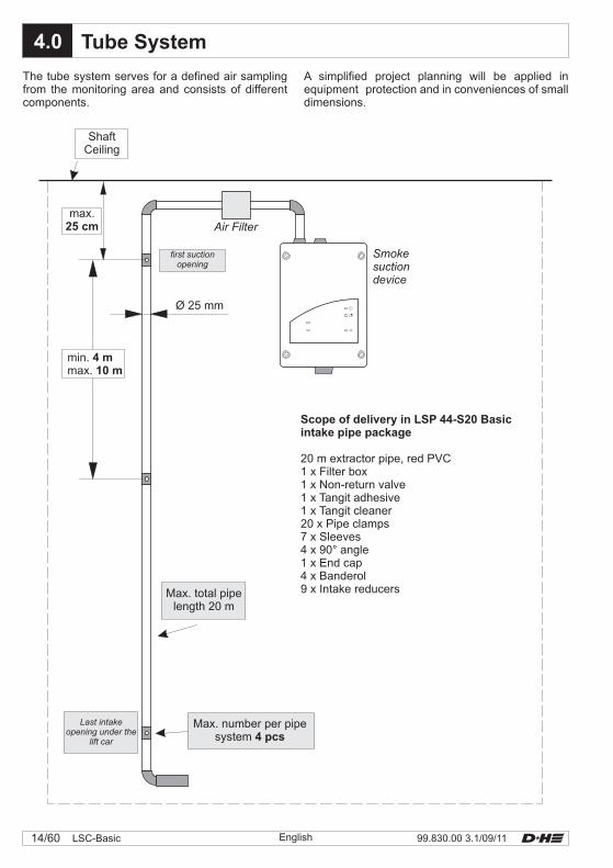
Smokesuctiondevice
Air Filter
Ø 25 mm
min.max.
4 m10 m
max.25 cm
Last intakeopening under the
lift car
Max. number per pipesystem 4 pcs
Max. total pipelength 20 m
first suctionopening
ShaftCeiling
Scope of delivery in LSP 44-S20 Basicintake pipe package
20 m extractor pipe, red PVC1 x Filter box1 x Non-return valve1 x Tangit adhesive1 x Tangit cleaner20 x Pipe clamps7 x Sleeves4 x 90° angle1 x End cap4 x Banderol9 x Intake reducers
The tube system serves for a defined air samplingfrom the monitoring area and consists of differentcomponents.
Tube System
A simplified project planning will be applied inequipment protection and in conveniences of smalldimensions.
15/6099.830.00 3.1/09/11 LSC-BasicEnglish
4.1
1
2
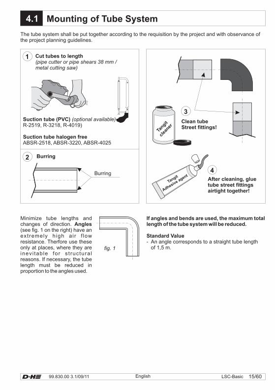
Mounting of Tube System
Burring
fig. 1
Cut tubes to length(pipe cutter or pipe shears 38 mm /metal cutting saw)
The tube system shall be put together according to the requisition by the project and with observance ofthe project planning guidelines.
Burring
Suction tube (PVC)
Suction tube halogen free
(optional available)R-2519, R-3218, R-4019)
ABSR-2518, ABSR-3220, ABSR-4025
Minimize tube lengths andchanges of direction.(see fig. 1 on the right) have anextremely high ai r f lowresistance. Therfore use theseonly at places, where they areinev i tab le for s t ruc tura lreasons. If necessary, the tubelength must be reduced inproportion to the angles used.
Angles
4
3
After cleaning, gluetube street fittingsairtight together!
Clean tubeStreet fittings!
If angles and bends are used, the maximum totallength of the tube system will be reduced.
Standard Value- An angle corresponds to a straight tube length
of 1,5 m.
Tangit
clea
ner
Tangit
Adhesive agent
99.830.00 3.1/09/1116/60 LSC-Basic English
X.x4.2
1
2
4
3
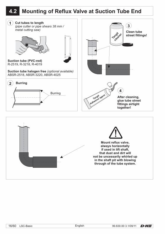
Mounting of Reflux Valve at Suction Tube End
Mount reflux valve,always horizontallyif used in lift shaft,
that dust and dirt willnot be uncessarily whirled upin the shaft pit with blowingthrough of the tube system.
Cut tubes to length(pipe cutter or pipe shears 38 mm /metal cutting saw)
Burring
Burring
Suction tube (PVC-red)
Suction tube halogen free
R-2519, R-3218, R-4019
ABSR-2518, ABSR-3220, ABSR-4025(optional available)
After cleaning,glue tube streetfittings airtighttogether!
Clean tubestreet fittings!
Tangit
clea
ner
Tangit
Adhesive agent
17/6099.830.00 3.1/09/11 LSC-BasicEnglish
4.3
4.4
E
D
C
B
A
10987654321
SHEV-control panel
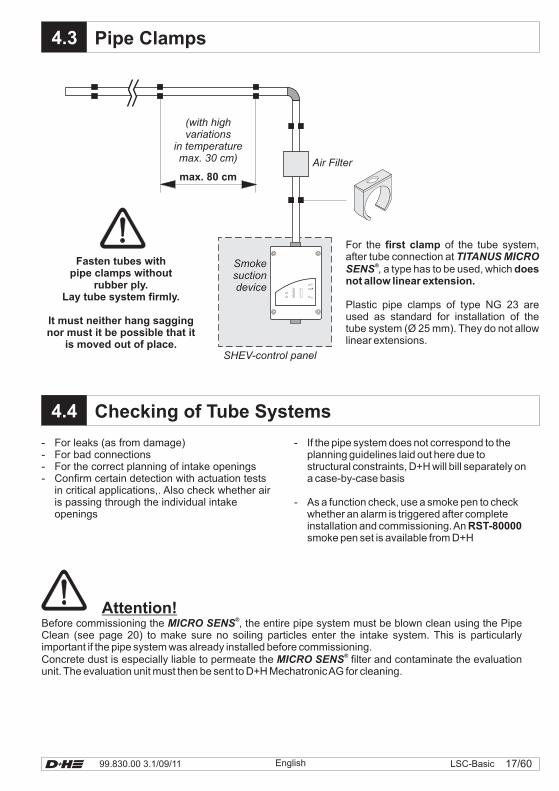
Checking of Tube Systems
Pipe Clamps
Smokesuctiondevice
For the of the tube system,after tube connection at
a type has to be used, which
Plastic pipe clamps of type NG 23 areused as standard for installation of thetube system (Ø 25 mm). They do not allowlinear extensions.
first clamp
doesnot allow linear extension.
TITANUS MICROSENS
®,
(with highvariations
in temperaturemax. 30 cm)
max. 80 cm
Fasten tubes withpipe clamps without
rubber ply.Lay tube system firmly.
It must neither hang saggingnor must it be possible that it
is moved out of place.
Air Filter
- For leaks (as from damage)- For bad connections- For the correct planning of intake openings- Confirm certain detection with actuation tests
in critical applications,. Also check whether airis passing through the individual intakeopenings
- If the pipe system does not correspond to theplanning guidelines laid out here due tostructural constraints, D+H will bill separately ona case-by-case basis
- As a function check, use a smoke pen to checkwhether an alarm is triggered after completeinstallation and commissioning.Ansmoke pen set is available from D+H
RST-80000
Attention!Before commissioning the , the entire pipe system must be blown clean using the PipeClean (see page 20) to make sure no soiling particles enter the intake system. This is particularlyimportant if the pipe system was already installed before commissioning.Concrete dust is especially liable to permeate the filter and contaminate the evaluationunit. The evaluation unit must then be sent to D+H MechatronicAG for cleaning.
MICRO SENS
MICRO SENS
®
®
99.830.00 3.1/09/1118/60 LSC-Basic English
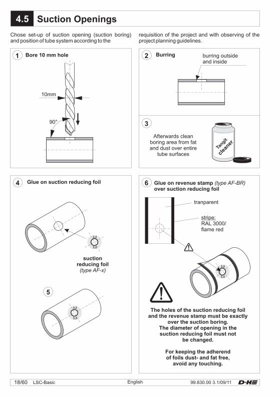
4.5
10mm
90°
3.2
3.2
3.2
3.2
3.2
3.2
1 2
3
64
5
Tangit
clea
ner
Suction Openings
burring outsideand inside
Afterwards cleanboring area from fatand dust over entire
tube surfaces
stripe:RAL 3000/flame red
tranparent
Glue on revenue stampover suction reducing foil
(type AF-BR)
suctionreducing foil(type AF-x)
Bore 10 mm hole Burring
Glue on suction reducing foil
Chose set-up of suction opening (suction boring)and position of tube system according to the
The holes of the suction reducing foiland the revenue stamp must be exactly
over the suction boring.The diameter of opening in thesuction reducing foil must not
be changed.
For keeping the adherendof foils dust- and fat free,
avoid any touching.
requisition of the project and with observing of theproject planning guidelines.
19/6099.830.00 3.1/09/11 LSC-BasicEnglish
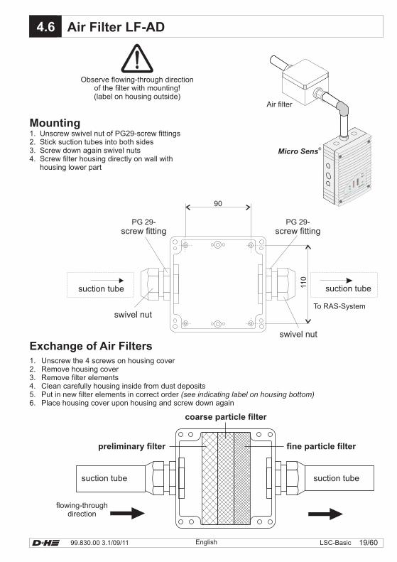
X.x4.6 Air Filter LF-AD
110
90
To RAS-System
Micro Sens®
TITANUS MICRO·S
ENS®
E
D
C
B
A
10987654321
Air filter
Observe flowing-through directionof the filter with mounting!(label on housing outside)
PG 29-screw fitting
swivel nut
Mounting1. Unscrew swivel nut of PG29-screw fittings2. Stick suction tubes into both sides3. Screw down again swivel nuts4. Screw filter housing directly on wall with
housing lower part
Exchange of Air Filters1. Unscrew the 4 screws on housing cover2. Remove housing cover3. Remove filter elements4. Clean carefully housing inside from dust deposits5. Put in new filter elements in correct order6. Place housing cover upon housing and screw down again
(see indicating label on housing bottom)
preliminary filter
coarse particle filter
fine particle filter
suction tubesuction tube
flowing-throughdirection
PG 29-screw fitting
swivel nut
suction tubesuction tube
99.830.00 3.1/09/1120/60 LSC-Basic English
X.x4.7
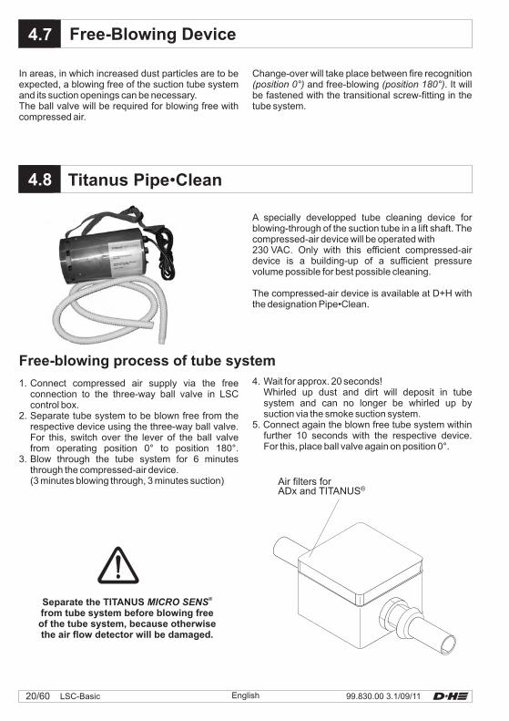
X.x4.8 Titanus Pipe Clean•
Free-Blowing Device
A specially developped tube cleaning device forblowing-through of the suction tube in a lift shaft. Thecompressed-air device will be operated with230 VAC. Only with this efficient compressed-airdevice is a building-up of a sufficient pressurevolume possible for best possible cleaning.
The compressed-air device is available at D+H withthe designation Pipe•Clean.
1. Connect compressed air supply via the freeconnection to the three-way ball valve in LSCcontrol box.
2. Separate tube system to be blown free from therespective device using the three-way ball valve.For this, switch over the lever of the ball valvefrom operating position 0° to position 180°.
3. Blow through the tube system for 6 minutesthrough the compressed-air device.(3 minutes blowing through, 3 minutes suction)
4. Wait for approx. 20 seconds!Whirled up dust and dirt will deposit in tubesystem and can no longer be whirled up bysuction via the smoke suction system.
5. Connect again the blown free tube system withinfurther 10 seconds with the respective device.For this, place ball valve again on position 0°.
Free-blowing process of tube system
In areas, in which increased dust particles are to beexpected, a blowing free of the suction tube systemand its suction openings can be necessary.The ball valve will be required for blowing free withcompressed air.
Separate the TITANUSfrom tube system before blowing freeof the tube system, because otherwisethe air flow detector will be damaged.
MICRO SENS®
Change-over will take place between fire recognitionand free-blowing . It will
be fastened with the transitional screw-fitting in thetube system.
(position 0°) (position 180°)
Air filters forADx and TITANUS®
21/6099.830.00 3.1/09/11 LSC-BasicEnglish
X.x5.0
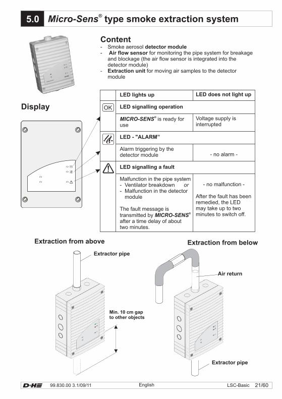
LED lights up
LED signalling operation
LED - "ALARM”
LED signalling a fault
MICRO-SENS
MICRO-SENS
is ready foruse
Alarm triggering by thedetector module
Malfunction in the pipe system- Ventilator breakdown- Malfunction in the detector
module
The fault message istransmitted byafter a time delay of abouttwo minutes.
®
®
or
LED does not light up
Voltage supply isinterrupted
- no alarm -
- no malfunction -
After the fault has beenremedied, the LEDmay take up to twominutes to switch off.
Micro-Sens® type smoke extraction system
Content- Smoke aerosol- for monitoring the pipe system for breakage
and blockage (the air flow sensor is integrated into thedetector module)
- for moving air samples to the detectormodule
detector moduleAir flow sensor
Extraction unit
Display
Air return
Extractor pipe
Extraction from above
Min. 10 cm gapto other objects
Extraction from below
Extractor pipe
99.830.00 3.1/09/1122/60 LSC-Basic English
X.x5.1
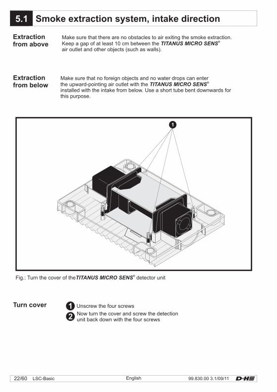
Extractionfrom above
Make sure that there are no obstacles to air exiting the smoke extraction.Keep a gap of at least 10 cm between theair outlet and other objects (such as walls).
TITANUS MICRO SENS®
Extractionfrom below
Make sure that no foreign objects and no water drops can enterthe upward-pointing air outlet with theinstalled with the intake from below. Use a short tube bent downwards forthis purpose.
TITANUS MICRO SENS®
Turn cover Unscrew the four screws
Now turn the cover and screw the detectionunit back down with the four screws
12
1
Fig.: Turn the cover of the detector unitTITANUS MICRO SENS®
Smoke extraction system, intake direction
23/6099.830.00 3.1/09/11 LSC-BasicEnglish
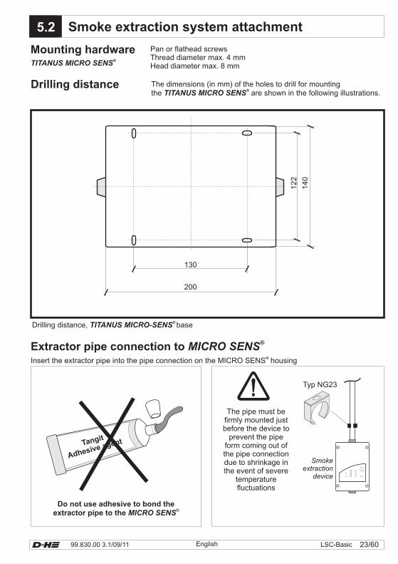
X.x5.2 Smoke extraction system attachment
JY (St) Y2x2x0,6
E
D
C
B
A
10987654321
Smokeextraction
device
Typ NG23
Insert the extractor pipe into the pipe connection on the MICRO SENS housing®
Extractor pipe connection to MICRO SENS®
The pipe must befirmly mounted justbefore the device to
prevent the pipeform coming out ofthe pipe connectiondue to shrinkage inthe event of severe
temperaturefluctuations
Do not use adhesive to bond theextractor pipe to the MICRO SENS
®
Tangit
Adhesive agent
Mounting hardware Pan or flathead screwsThread diameter max. 4 mmHead diameter max. 8 mmTITANUS MICRO SENS
®
Drilling distance The dimensions (in mm) of the holes to drill for mountingthe are shown in the following illustrations.TITANUS MICRO SENS
®
200
140
122
130
Drilling distance, baseTITANUS MICRO-SENS®
99.830.00 3.1/09/1124/60 LSC-Basic English
Testing the TITANUS MICRO SENS
MICRO SENS
®
®
Once initialization has been successfully completed,you can function-test it by blowing smoke from acigarette or the D+H smoke pen set into one of thepipe intake openings.
The must be set for the rightsensitivity depending on the system.
This adjustment must be performed separately usingthe diagnostic software. See the planninginstructions on page 13.
Attention!
X.x5.3
X4PIN 1 an 2PIN 2 an 3
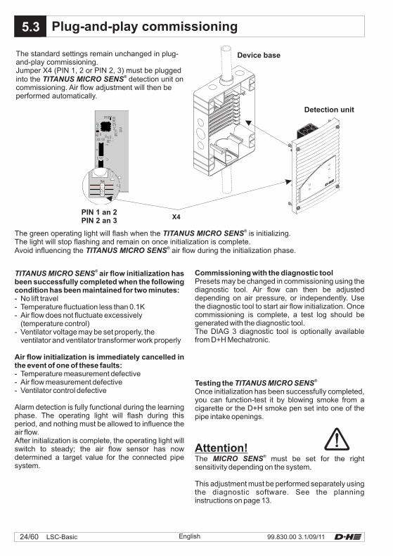
Device base
Detection unit
The standard settings remain unchanged in plug-and-play commissioning.Jumper X4 (PIN 1, 2 or PIN 2, 3) must be pluggedinto the detection unit oncommissioning. Air flow adjustment will then beperformed automatically.
TITANUS MICRO SENS®
The green operating light will flash when the is initializing.The light will stop flashing and remain on once initialization is complete.Avoid influencing the air flow during the initialization phase.
TITANUS MICRO SENS
TITANUS MICRO SENS
®
®
TITANUS MICRO SENS® air flow initialization has
been successfully completed when the followingcondition has been maintained for two minutes:
Air flow initialization is immediately cancelled inthe event of one of these faults:
- No lift travel- Temperature fluctuation less than 0.1K- Air flow does not fluctuate excessively
(temperature control)- Ventilator voltage may be set properly, the
ventilator and ventilator transformer work properly
- Temperature measurement defective- Air flow measurement defective- Ventilator control defective
Alarm detection is fully functional during the learningphase. The operating light will flash during thisperiod, and nothing must be allowed to influence theair flow.After initialization is complete, the operating light willswitch to steady; the air flow sensor has nowdetermined a target value for the connected pipesystem.
Commissioning with the diagnostic toolPresets may be changed in commissioning using thediagnostic tool. Air flow can then be adjusteddepending on air pressure, or independently. Usethe diagnostic tool to start air flow initialization. Oncecommissioning is complete, a test log should begenerated with the diagnostic tool.The DIAG 3 diagnostic tool is optionally availablefrom D+H Mechatronic.
Plug-and-play commissioning
25/6099.830.00 3.1/09/11 LSC-BasicEnglish
5.9X.x5.4
MICRO·SENS
MICRO SENSMICRO SENS
MICRO SENS
®
®
®
®
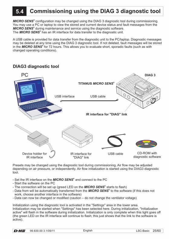
configuration may be changed using the DIAG 3 diagnostic tool during commissioning.You may use a PC or laptop to view the stored and current device status and fault messages from the
during maintenance and service using the diagnostic software.The has an IR interface for data transfer to the diagnostic unit.
A USB cable is provided for data transfer from the diagnostic unit to the PC/laptop. Diagnostic messagesmay be deleted at any time using the DIAG 3 diagnostic tool. If not deleted, fault messages will be storedin the for 72 hours. This allows you to evaluate short, sporadic faults (such as withchanged operating conditions).
Presets may be changed using the diagnostic tool during commissioning. Air flow may be adjusteddepending on air pressure, or independently. Air flow initialization is started using the DIAG3 diagnostictool.
- Set the IR interface on the and connect to the PC- Start the software on the PC- The connection will be set up (greed LED on the starts to flash)- Data from will be automatically transferred from the to the software (if this does not
work, choose another interface in the software)- Data can now be changed or modified (caution – do not change the ventilator voltage)
Initialization using the diagnostic tool is activated in the "Settings" area in the lower area.Initialization may be started when "Settings" has been selected here. During initialization, "Initializationactive" will flash in the software during initialization. Initialization is only complete when this light goes off(the green LED on the IR interface will continue to flash; this just shows that the link to the software isactive).
MICRO SENS
MICRO SENSMICRO SENS
®
®
®
DIAG3 diagnostic tool
USB cableUSB interface
PC
TITANUS MICRO SENS®
IR interface for "DIAG" link
TITANUS MICRO·S
ENS®
ED
CB
A
109
87
65
43
21
DIAG 3
DIAG 3
DIAG 3
USB cable CD-ROM withdiagnostic software
IR interface for"DIAG" link
Device holder forIR interface
Commissioning using the DIAG 3 diagnostic tool
99.830.00 3.1/09/1126/60 LSC-Basic English
X.x6.0
X.x
X.x
6.2
6.1
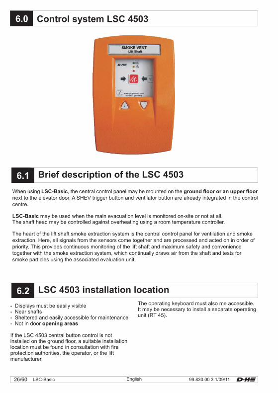
When using , the central control panel may be mounted on thenext to the elevator door. A SHEV trigger button and ventilator button are already integrated in the controlcentre.
may be used when the main evacuation level is monitored on-site or not at all.The shaft head may be controlled against overheating using a room temperature controller.
The heart of the lift shaft smoke extraction system is the central control panel for ventilation and smokeextraction. Here, all signals from the sensors come together and are processed and acted on in order ofpriority. This provides continuous monitoring of the lift shaft and maximum safety and conveniencetogether with the smoke extraction system, which continually draws air from the shaft and tests forsmoke particles using the associated evaluation unit.
LSC-Basic ground floor or an upper floor
LSC-Basic
Control system LSC 4503
- Displays must be easily visible- Near shafts
- Not in door
If the LSC 4503 central button control is notinstalled on the ground floor, a suitable installationlocation must be found in consultation with fireprotection authorities, the operator, or the liftmanufacturer.
- Sheltered and easily accessible for maintenanceopening areas
The operating keyboard must also me accessible.It may be necessary to install a separate operatingunit (RT 45).
LSC 4503 installation location
Brief description of the LSC 4503
SMOKE VENTLift Shaft
27/6099.830.00 3.1/09/11 LSC-BasicEnglish
6.3
M
JY (St) Y6x2x0,6
M
JY (St) Y2x2x0,6
JY (St) Y2x2x0,6
JY (St) Y2x2x0,6
JY (St) Y3x2x0,6
JY (St) Y2x2x0,6
JY (St) Y2x2x0,6
JY (St) Y2x2x0,6
JY (St) Y2x2x0,6
Smoke extractionsystem
Key-operated
vent button
External controlBMS
Signal contactLift
Signal contactCO2-sensor
Signal contactGLT
Smoke vent buttonwith
ventilator button
230 VAC / 50HzNot possible to switch off
Drive
Wind-/raindetector
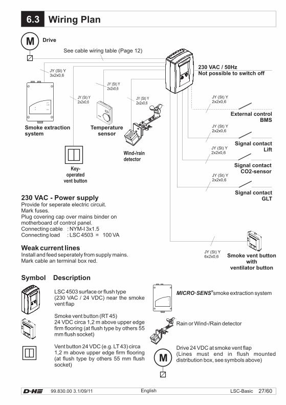
See cable wiring table (Page 12)
Symbol Description
Wiring Plan
LSC 4503 surface or flush type(230 VAC / 24 VDC) near the smokevent flap
Smoke vent button (RT 45)
Vent button 24 VDC (e.g. LT 43) circa1,2 m above upper edge firm flooring(at flush type by others 55 mm flushsocket)
24 VDC circa 1,2 m above upper edgefirm flooring (at flush type by others 55mm flush socket)
230 VAC - Power supplyProvide for seperate electric circuit.Mark fuses.Plug covering cap over mains binder onmotherboard of control panel.
Install and feed seperately from supply mains.Mark cable an terminal box red.
Connecting cable : NYM-I 3x1.5Connecting load : LSC 4503 = 100 VA
Weak current lines
MICRO·SENS®smoke extraction system
Rain or Wind-/Rain detector
Drive 24 VDC at smoke vent flap(Lines must end in flush mounteddistribution box, see symbols above)
Temperaturesensor
SMOKE VENT
LiftShaft
99.830.00 3.1/09/1128/60 LSC-Basic English
6.4
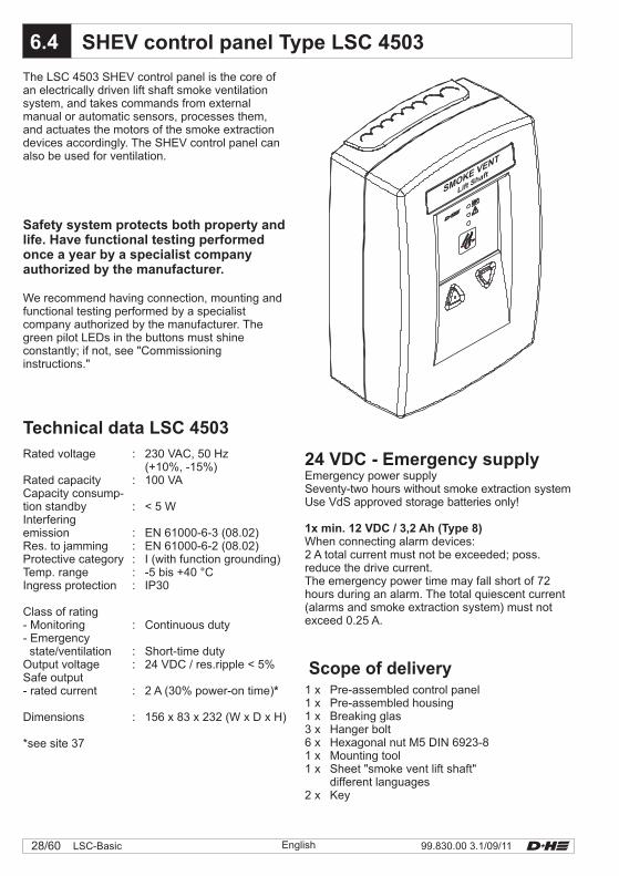
24 VDC - Emergency supplyEmergency power supplySeventy-two hours without smoke extraction systemUse VdS approved storage batteries only!
When connecting alarm devices:2 A total current must not be exceeded; poss.reduce the drive current.The emergency power time may fall short of 72hours during an alarm. The total quiescent current(alarms and smoke extraction system) must notexceed 0.25 A.
1x min. 12 VDC / 3,2 Ah (Type 8)
1 x Pre-assembled control panel1 x Pre-assembled housing1 x Breaking glas3 x Hanger bolt6 x Hexagonal nut M5 DIN 6923-81 x Mounting tool1 x Sheet "smoke vent lift shaft"
different languages2 x Key
Scope of delivery
Rated voltage : 230 VAC, 50 Hz(+10%, -15%)
Rated capacity : 100 VACapacity consump-tion standby : < 5 WInterferingemission : EN 61000-6-3 (08.02)Res. to jamming : EN 61000-6-2 (08.02)Protective category : I (with function grounding)Temp. range : -5 bis +40 °CIngress protection : IP30
Class of rating- Monitoring : Continuous duty- Emergencystate/ventilation : Short-time duty
Output voltage : 24 VDC / res.ripple < 5%Safe output- rated current : 2 A (30% power-on time)
Dimensions : 156 x 83 x 232 (W x D x H)
*see site 37
*
SHEV control panel Type LSC 4503
The LSC 4503 SHEV control panel is the core ofan electrically driven lift shaft smoke ventilationsystem, and takes commands from externalmanual or automatic sensors, processes them,and actuates the motors of the smoke extractiondevices accordingly. The SHEV control panel canalso be used for ventilation.
Technical data LSC 4503
Safety system protects both property andlife. Have functional testing performedonce a year by a specialist companyauthorized by the manufacturer.
We recommend having connection, mounting andfunctional testing performed by a specialistcompany authorized by the manufacturer. Thegreen pilot LEDs in the buttons must shineconstantly; if not, see "Commissioninginstructions."
Power
230 VAC Battery Detector LineDrive
GroupModule
Connector
X2
OF
F
ServiceX1
0Reset/I
S1
81
ON
www.dh-partner.com
Service
12 month
www.dh-partner.com
OK
www.dh-partner.com
Service
12 month
SMOKE VENT
LiftShaft
29/6099.830.00 3.1/09/11 LSC-BasicEnglish
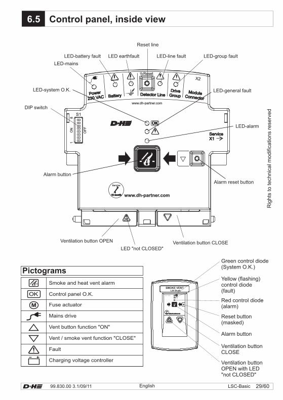
X.x6.5 Control panel, inside view
PowerPower
230 VAC230 VAC BatteryBattery Detector LineDetector LineDriveDrive
GroupGroupModuleModule
ConnectorConnector
X2
OF
F
ServiceX1ServiceX1
0Reset/I
S1
81
ON
www.dh-partner.com
Service
12 month12 month
www.dh-partner.com
LED-system O.K.
DIP switch
LED-mains
LED-alarm
LED-group faultLED-battery fault LED earthfault
Reset line
LED-line fault
LED-general fault
LED "not CLOSED"Ventilation button CLOSE
Alarm button
Alarm reset button
Ventilation button OPEN
OK
M
Pictograms
Smoke and heat vent alarm
Control panel O.K.
Fuse actuator
Mains drive
Vent button function "ON"
Vent / smoke vent function "CLOSE"
Fault
Charging voltage controller
www.dh-partner.comwww.dh-partner.com
Service
12 month12 month
Green control diode(System O.K.)
Yellow (flashing)control diode(fault)
Red control diode(alarm)
Reset button(masked)
Alarm button
Ventilation buttonOPEN with LED"not CLOSED"
Ventilation buttonCLOSE
Rig
hts
tote
chnic
al m
odifi
catio
ns
rese
rved
SMOKE VENTLift Shaft
99.830.00 3.1/09/1130/60 LSC-Basic English
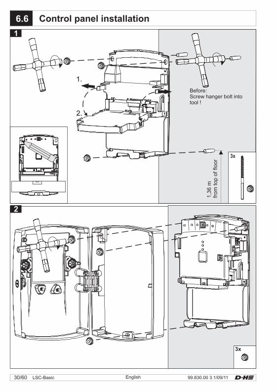
X.x6.6 Control panel installation
2
1
3x
1.
2.
Before:Screw hanger bolt intotool !
1,3
6m
from
top
offlo
or
3x
1.
2.
31/6099.830.00 3.1/09/11 LSC-BasicEnglish
1.
2.
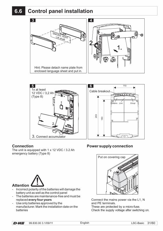
6.6 Control panel installation
SMOKE VENTLift shaft
3. Connect accumulator
1.
2.
3 4
51x at least12 VDC / 3,2 Ah(Type 8)
Hint: Please detach name plate fromenclosed language sheet and put in.
Cable breakout
LineMains Group
110
183203
6
Attention- Incorrect polarity of the batteries will damage the
battery unit as well as the control panel- The batteries are maintenance-free and must be
replaced- Use only batteries approved by the
manufacturer. Mark the installation date on thebatteries
every four years
Power supply connectionConnectionThe unit is equipped with 1 x 12 VDC / 3.2 Ahemergency battery (Type 8)
Connect the mains power via the L1, Nand PE terminals.These are protected by a micro-fuse.Check the supply voltage after switching on.
Put on covering cap
99.830.00 3.1/09/1132/60 LSC-Basic English
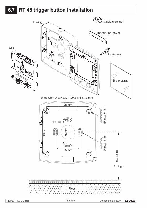
X.x6.7
95 mm
95
mm
55
mm
55 mm
Øm
ax.
5m
mØ
max.
4m
m
ca.1,5
m
Floor
www.dh-partner.com
Service
12 month
D67201A
01
12
34
56
78
910
11 12
�+49 (0) 1805 - 26 26 40
RT
45
RT
45-L
T
Cable grommet
Inscription cover
Plastic key
Break glass
Housing
Use
Dimension W x H x D: 129 x 138 x 39 mm
RT 45 trigger button installation
Smoke VentLift Shaft
Service
12 monthwww.dh-partner.com+49 (0) 1805 - 26 26 40
Smoke VentLift Shaft
Service
12 monthwww.dh-partner.com+49 (0) 1805 - 26 26 40
Smoke VentLift Shaft
Service
12 monthwww.dh-partner.com+49 (0) 1805 - 26 26 40
33/6099.830.00 3.1/09/11 LSC-BasicEnglish
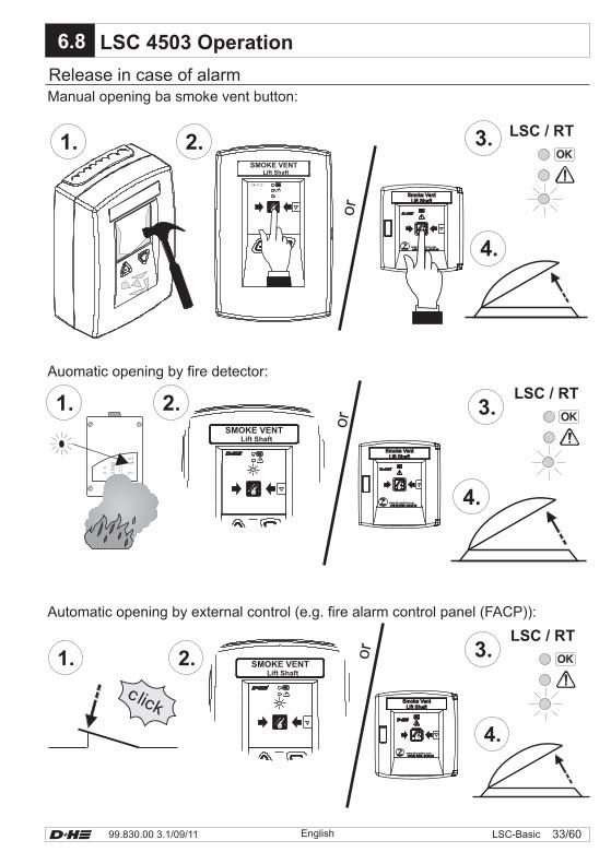
LSC 4503 Operation
E
D
C
B
A
10987654321
1. 2. 3.
4.
LSC / RT
3.1. 2.
SMOKE VENTLift Shaft
LSC / RT
4.
click
1. 2.
4.
3.LSC / RT
Release in case of alarmManual opening ba smoke vent button:
Auomatic opening by fire detector:
or
or
Automatic opening by external control (e.g. fire alarm control panel (FACP)):
or
6.8
SMOKE VENTLift Shaft
SMOKE VENTLift Shaft
Smoke VentLift Shaft
Service
12 month12 monthwww.dh-partner.com+49 (0) 1805 - 26 26 40+49 (0) 1805 - 26 26 40
Smoke VentLift Shaft
ServiceService
12 month12 monthwww.dh-partner.com+49 (0) 1805 - 26 26 40+49 (0) 1805 - 26 26 40
Smoke VentLift Shaft
Service
12 month12 monthwww.dh-partner.com+49 (0) 1805 - 26 26 40+49 (0) 1805 - 26 26 40
Service
12 monthwww.dh-partner.com+49 (0) 1805 - 26 26 40
99.830.00 3.1/09/1134/60 LSC-Basic English
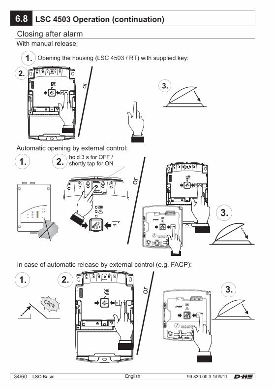
6.8 LSC 4503 Operation (continuation)
2.
1.
3.
3.
Closing after alarmWith manual release:
Opening the housing (LSC 4503 / RT) with supplied key:
Automatic opening by external control:hold 3 s for OFF /shortly tap for ON
or
or
In case of automatic release by external control (e.g. FACP):
or
E
D
C
B
A
10987654321
Service
12 monthwww.dh-partner.com+49 (0) 1805 - 26 26 40
35/6099.830.00 3.1/09/11 LSC-BasicEnglish
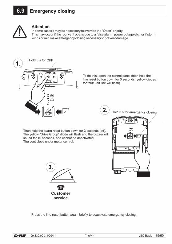
Emergency closing
Hold 3 s for OFF
Hold 3 s for emergency closing
6.9
AttentionIn some cases it may be necessary to override the "Open" priority.This may occur if the roof vent opens due to a false alarm, power outage etc., or if stormwinds or rain make emergency closing necessary to prevent damage.
To do this, open the control panel door, hold theline reset button down for 3 seconds (yellow diodesfor fault und line will flash)
Then hold the alarm reset button down for 3 seconds (off).The yellow "Drive Group" diode will flash and the buzzer willsound for 10 seconds, and cannot be deactivated.The vent close under motor control.
Press the line reset button again briefly to deactivate emergency closing.
Customerservice
99.830.00 3.1/09/1136/60 LSC-Basic English
The shaft has a permanent opening at the top that serves to release smoke in case of fire, but allowsheated air to escape uncontrolled. You can avoid uncontrolled energy losses and substantially lower youroperating costs using the LSC system.
Shaft ventilation must be assured during maintenance work at the top of the shaft. Before maintenance,the service technician shuts off the SHEV line with the reset button in the LSC 4503 (hold for 3 sec). Theventilation flap will open automatically until the SHEV line is reactivated after maintenance work (hold for3 sec again).This ensures good air quality in the shaft for maintenance work.
A room thermostat may be used to monitor the temperature in the shaft head or the machine room to setan upper temperature of up to 30°C.If this limit value is exceeded, the 24 VDC electric drive will move the ventilation and smoke extractionflap to the open position.
Optional automatic ventilator operation is possible with other sensors.
The shape of the lift shaft and the air flow caused by the movement of the lift up and down in the shaftmakes ventilation and smoke extraction of the shaft very important.If necessary, ventilation may be intelligently controlled using sensors in the shaft.
The LSC system may be equipped with a CO2 sensor in the shaft for permanent air quality monitoringand air exchange control.In addition, any desired ventilation intervals may be programmed by an optional timer, although anautomatic function makes this almost superfluous. The ventilation flap may be opened for fifteen minutesevery five hours for regular air exchange.
The system makes it possible to use the SHEV for ventilation as well. There are several ways todo this.
The LSC 4503 is a .The system's control is designed for the ventilation and smoke extraction flaps to move to theopen position automatically. There are conditions that may lead to complete opening of the flaps(including a dome skylight) for functional reasons such as SHEV actuation. This may lead to raindamage in the elevator shaft. Roof flaps should be planned and installed in such a way that noelectrical components (elevator drive or mechanism) are located directly underneath.If necessary, consult your D+H service and sales partner to install .
An alternative solution is the installation of a permanent opening using standard ventilationhoods, and then fitting it with a closure flap on the inside on the shaft ceiling (e.g. louverelement).It is also possible to reduce the opening angle as long as the necessary opening cross-section isretained.
An opening in the shaft wall is always preferable.
Controlled shaft ventilation
Room thermostat
fail-safe system
rain-proof roof flaps
X.x7.0 Demand-optimized ventilation
37/6099.830.00 3.1/09/11 LSC-BasicEnglish
X.x7.1
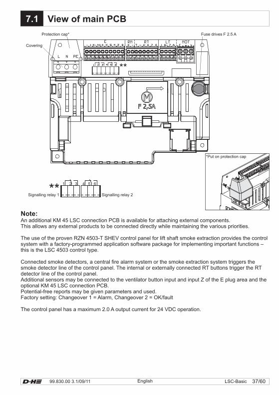
Note:An additional KM 45 LSC connection PCB is available for attaching external components.This allows any external products to be connected directly while maintaining the various priorities.
The use of the proven RZN 4503-T SHEV control panel for lift shaft smoke extraction provides the controlsystem with a factory-programmed application software package for implementing important functions –this is the LSC 4503 control type.
Connected smoke detectors, a central fire alarm system or the smoke extraction system triggers thesmoke detector line of the control panel. The internal or externally connected RT buttons trigger the RTdetector line of the control panel.Additional sensors may be connected to the ventilator button input and input Z of the E plug area and theoptional KM 45 LSC connection PCB.Potential-free reports may be given parameters and used.Factory setting: Changeover 1 = Alarm, Changeover 2 = OK/fault
The control panel has a maximum 2.0 A output current for 24 VDC operation.
View of main PCB
Fuse drives F 2.5 AProtection cap*
Covering
*Put on protection cap
**
**Signalling relay 1 Signalling relay 2
4 5 61 2 3
99.830.00 3.1/09/1138/60 LSC-Basic English
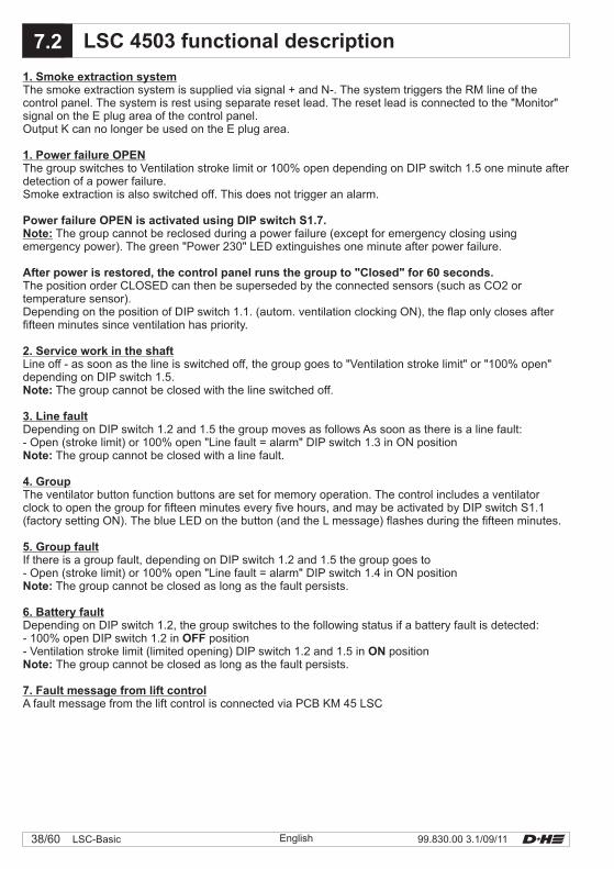
1. Smoke extraction system
2. Service work in the shaft
3. Line fault
4. Group
5. Group fault
6. Battery fault
7. Fault message from lift control
The smoke extraction system is supplied via signal + and N-. The system triggers the RM line of thecontrol panel. The system is rest using separate reset lead. The reset lead is connected to the "Monitor"signal on the E plug area of the control panel.Output K can no longer be used on the E plug area.
Line off - as soon as the line is switched off, the group goes to "Ventilation stroke limit" or "100% open"depending on DIP switch 1.5.
The group cannot be closed with the line switched off.
Depending on DIP switch 1.2 and 1.5 the group moves as follows As soon as there is a line fault:- Open (stroke limit) or 100% open "Line fault = alarm" DIP switch 1.3 in ON position
The group cannot be closed with a line fault.
The ventilator button function buttons are set for memory operation. The control includes a ventilatorclock to open the group for fifteen minutes every five hours, and may be activated by DIP switch S1.1(factory setting ON). The blue LED on the button (and the L message) flashes during the fifteen minutes.
If there is a group fault, depending on DIP switch 1.2 and 1.5 the group goes to- Open (stroke limit) or 100% open "Line fault = alarm" DIP switch 1.4 in ON position
The group cannot be closed as long as the fault persists.
Depending on DIP switch 1.2, the group switches to the following status if a battery fault is detected:- 100% open DIP switch 1.2 in position- Ventilation stroke limit (limited opening) DIP switch 1.2 and 1.5 in position
The group cannot be closed as long as the fault persists.
A fault message from the lift control is connected via PCB KM 45 LSC
1. Power failure OPEN
Note:
The group switches to Ventilation stroke limit or 100% open depending on DIP switch 1.5 one minute afterdetection of a power failure.Smoke extraction is also switched off. This does not trigger an alarm.
The group cannot be reclosed during a power failure (except for emergency closing usingemergency power). The green "Power 230" LED extinguishes one minute after power failure.
The position order CLOSED can then be superseded by the connected sensors (such as CO2 ortemperature sensor).Depending on the position of DIP switch 1.1. (autom. ventilation clocking ON), the flap only closes afterfifteen minutes since ventilation has priority.
Power failure OPEN is activated using DIP switch S1.7.
After power is restored, the control panel runs the group to "Closed" for 60 seconds.
Note:
Note:
Note:
OFFON
Note:
X.x7.2 LSC 4503 functional description
Power
230 VAC Battery Detector LineDrive
GroupModule
Connector
X2
OF
F
ServiceX1
0Reset/I
S1
81
ON
www.dh-partner.com
39/6099.830.00 3.1/09/11 LSC-BasicEnglish
PowerPower
230 VAC230 VAC BatteryBattery Detector LineDetector LineDriveDrive
GroupGroupModuleModule
ConnectorConnector
X2
OF
F
ServiceX1ServiceX1
0Reset/I
S1
81
ON
www.dh-partner.com
1 2 3 4 5 6 7 8
ON
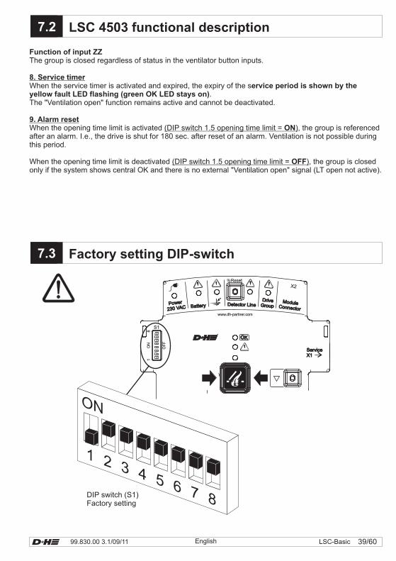
DIP switch (S1)Factory setting
Function of input ZZ
ervice period is shown by theyellow fault LED flashing (green OK LED stays on)
The group is closed regardless of status in the ventilator button inputs.
When the service timer is activated and expired, the expiry of the s.
The "Ventilation open" function remains active and cannot be deactivated.
When the opening time limit is activated , the group is referencedafter an alarm. I.e., the drive is shut for 180 sec. after reset of an alarm. Ventilation is not possible duringthis period.
When the opening time limit is deactivated , the group is closedonly if the system shows central OK and there is no external "Ventilation open" signal (LT open not active).
8. Service timer
9. Alarm resetON
OFF
(DIP switch 1.5 opening time limit = )
(DIP switch 1.5 opening time limit = )
X.x7.2
X.x7.3
LSC 4503 functional description
Factory setting DIP-switch
99.830.00 3.1/09/1140/60 LSC-Basic English
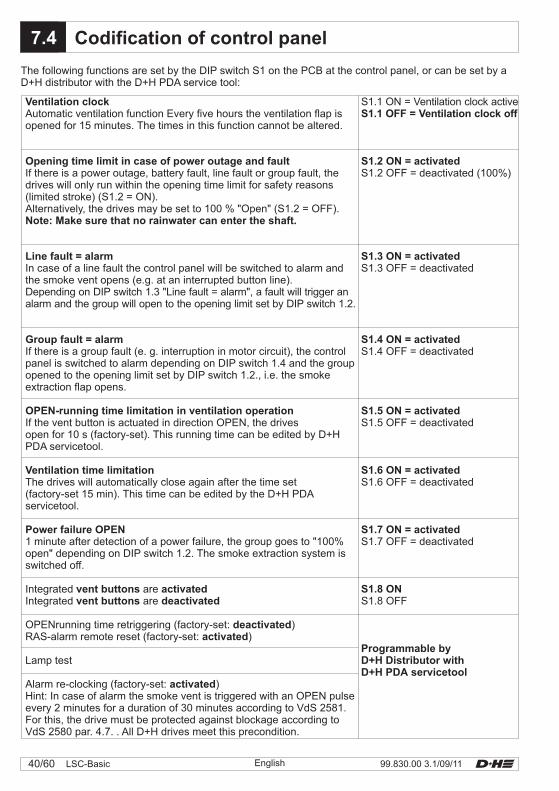
Ventilation clock
Opening time limit in case of power outage and fault
Note: Make sure that no rainwater can enter the shaft.
Line fault = alarm
Group fault = alarm
OPEN-running time limitation in ventilation operation
Ventilation time limitation
Power failure OPEN
vent buttons activated
deactivated
activated
Automatic ventilation function Every five hours the ventilation flap isopened for 15 minutes. The times in this function cannot be altered.
If there is a power outage, battery fault, line fault or group fault, thedrives will only run within the opening time limit for safety reasons(limited stroke) (S1.2 = ON).Alternatively, the drives may be set to 100 % "Open" (S1.2 = OFF).
In case of a line fault the control panel will be switched to alarm andthe smoke vent opens (e.g. at an interrupted button line).Depending on DIP switch 1.3 "Line fault = alarm", a fault will trigger analarm and the group will open to the opening limit set by DIP switch 1.2.
If there is a group fault (e. g. interruption in motor circuit), the controlpanel is switched to alarm depending on DIP switch 1.4 and the groupopened to the opening limit set by DIP switch 1.2., i.e. the smokeextraction flap opens.
If the vent button is actuated in direction OPEN, the drivesopen for 10 s (factory-set). This running time can be edited by D+HPDA servicetool.
The drives will automatically close again after the time set(factory-set 15 min). This time can be edited by the D+H PDAservicetool.
1 minute after detection of a power failure, the group goes to "100%open" depending on DIP switch 1.2. The smoke extraction system isswitched off.
Integrated are
OPENrunning time retriggering (factory-set: )RAS-alarm remote reset ( )
Lamp test
Alarm re-clocking (factory-set: )Hint: In case of alarm the smoke vent is triggered with an OPEN pulseevery 2 minutes for a duration of 30 minutes according to VdS 2581.For this, the drive must be protected against blockage according toVdS 2580 par. 4.7. . All D+H drives meet this precondition.
Integrated are
factory-set:
vent buttons deactivated
activated
S1.1 ON = Ventilation clock active
S1.2 OFF = (100%)
S1.3 OFF = deactivated
S1.4 OFF =
S1.5 OFF =
S1.6 OFF =
S1.7 OFF =
S1.8 OFF
S1.1 OFF = Ventilation clock off
S1.2 ON =
S1.3 ON = activated
S1.4 ON =
S1.5 ON =
S1.6 ON =
S1.7 ON =
S1.8 ON
Programmable byD+H Distributor withD+H PDA servicetool
activated
activated
activated
activated
activated
deactivated
deactivated
deactivated
deactivated
deactivated
The following functions are set by the DIP switch S1 on the PCB at the control panel, or can be set by aD+H distributor with the D+H PDA service tool:
X.x7.4 Codification of control panel
41/6099.830.00 3.1/09/11 LSC-BasicEnglish
X.x
X.x
7.4
7.5
Codification of control panel
Line switch-off
on off
flashing off
off on
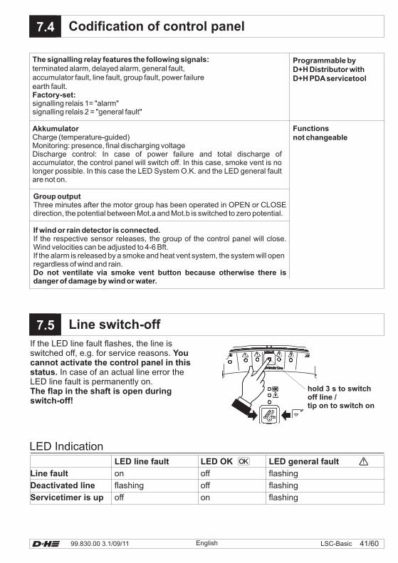
LED line fault LED OK LED general fault
Line fault flashing
flashing
flashing
Deactivated line
Servicetimer is up
LED Indication
hold 3 s to switchoff line /tip on to switch on
If the LED line fault flashes, the line isswitched off, e.g. for service reasons.
In case of an actual line error theLED line fault is permanently on.
Youcannot activate the control panel in thisstatus.
The flap in the shaft is open duringswitch-off!
Programmable byD+H Distributor withD+H PDAservicetool
Functionsnot changeable
The signalling relay features the following signals:
Factory-set:
Akkumulator
Group output
If wind or rain detector is connected.
Do not ventilate via smoke vent button because otherwise there isdanger of damage by wind or water.
terminated alarm, delayed alarm, general fault,accumulator fault, line fault, group fault, power failureearth fault.
signalling relais 1= "alarm"signalling relais 2 = "general fault"
Charge (temperature-guided)Monitoring: presence, final discharging voltageDischarge control: In case of power failure and total discharge ofaccumulator, the control panel will switch off. In this case, smoke vent is nolonger possible. In this case the LED System O.K. and the LED general faultare not on.
Three minutes after the motor group has been operated in OPEN or CLOSEdirection, the potential between Mot.a and Mot.b is switched to zero potential.
If the respective sensor releases, the group of the control panel will close.Wind velocities can be adjusted to 4-6 Bft.If the alarm is released by a smoke and heat vent system, the system will openregardless of wind and rain.
Connect mains.
Mains control on?........
99.830.00 3.1/09/1142/60 LSC-Basic English
1 2 3 4 5 6 7 8
ON
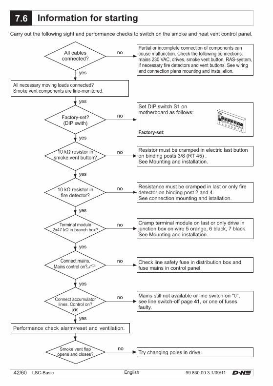
Carry out the following sight and performance checks to switch on the smoke and heat vent control panel.
yes
no
yes
no
yes
yes
yes
yes
yes
yes
no
no
no
no
no
no
Performance check alarm/reset and ventilation.
All cablesconnected?
All necessary moving loads connected?Smoke vent components are line-monitored.
Partial or incomplete connection of components cancouse malfunction. Check the following connections:mains 230 VAC, drives, smoke vent button, RAS-system,if necessary fire detectors and vent buttons. See wiringand connection plans mounting and installation.
Set DIP switch S1 onmotherboard as follows:
Factory-set?(DIP swith)
Factory-set:
X.x7.6 Information for starting
Resistor must be cramped in electric last buttonon binding posts 3/8 (RT 45) .See Mounting and installation.
Resistance must be cramped in last or only firedetector on binding post 2 and 4.See connection mounting and istallation.
Cramp terminal module on last or only drive injunction box on wire 5 orange, 6 black, 7 black.See Mounting and installation.
Check line safety fuse in distribution box andfuse mains in control panel.
Mains still not available or line switch on "0",see line switch-off page , or one of fusesfaulty.
41
Try changing poles in drive.
10 k resistor insmoke vent button?
Ω
10 k resistor infire detector?
Ω
Terminal module2x47 k in branch box?Ω
Connect accumulatorlines. Control on?
Smoke vent flapopens and closes?
43/6099.830.00 3.1/09/11 LSC-BasicEnglish
Red display diode must be on.Smoke vent must open. For closing wait until there isno more smoke in detector.Reset line in control panel (switch off/ switch on line),red display diode extinguishes in button andcontrol panel.Press masked button in control panel or in smokevent button. Smoke vent must close.The line can also be directly reset via smoke ventbutton, if remote reset is activated.For this, press masked button in smoke ventbutton (for 1 s).Red display diode extinguishes in button and incontrol panel.
Release external control.Smoke vent must open.Open contact in external system for closing, forexample by resetting of fire detector system.If smoke and heat exhaust do not automaticallyclose, press masked button in smoke ventbutton (1 s). Red display diodeextinguishes in button and control panel.Smoke vent must close.
Detach fuse MAINS in power distributor.Green mains indication diode on controlpanel must not be on.Repeat functional testing.Green control diode in smoke vent buttonsmust not be on.If "Power outage OPEN" is activated, the group willopen automatically. Reset the grid fuse in thebuilding's fuse box.
If severe dirt accumulation is visible or there are falsealarms, change the filter or replace the detector unit.
External control (optional):
Emergency supply:
Preperation:
Information:
Inpection:
Smoke vent button:
Automatic fire detectors:+ RAS-System
Notify user that the system is out of operationbefore starting with inspection.Notify user about false alarms.Interrupt or switch off monitored alarmindication and remote controls.
An overdue maintenance of the system will beindicated by the control panel after about 16 months.The yellow control diode in the control panel as wellas in the smoke vent button RT 45 will start flashing.
Amalfunction in the smoke vent system will becontinually indicated by the extinguished greencontrol diodes in the smoke vent buttons.Reset can be carried out by a specialist companyonly who has been authorized by the appliancemanufacturer.
Check all appliances and cable connectionsfor outer damage and dirt accumulation.Fire detectors, smoke vent buttons, smokevents and so on must not be impaired in theirfunction in structural changings.
Open smoke vent button .Press red button, red display diode is on inbutton and control panel.Smoke vent must open.Press masked button (1 s), red displaydiode extinguishes in button and controlpanel. Smoke vent must close.
Release smoke detector individual by D+Hsmoke detector tester or with D+H smoke pen(response delay circa 20 s).
Every six months and after repair by a specialist or staff, who has been introduced to the task.Eliminate failings at once. Keep control book.
7.7 Examination
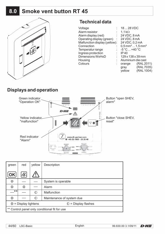
Displays and operation
OK
** Control panel only conditional fit for use
= Display lightens = Display flashes
Maintenance of system due
Malfunction
Alarm
System is operable
green red yellow Description
Button "open SHEV,alarm"
Green indicator"Operation OK"
Button "close SHEV,reset"
Yellow indicator"malfunction"
Red indicator"Alarm"
Technical dataVoltage : 18 ... 28 VDCAlarm resistor : 1,1 kAlarm display (red) : 24 VDC, 8 mAOperating display (green) : 24 VDC, 8 mAMalfunction display (yellow): 24 VDC, 0,2 mAConnection : 0,5 mm² ... 1,5 mm²Temperatur range : -5 °C ... +40 °CIngress protection : IP 40Dimensions WxHxD : 129 x 138 x 39 mmHousing : Aluminium die castColours orange (RAL2011)
gray (RAL7035)yellow (RAL1004)
�
:
X.x8.0 Smoke vent button RT 45
OK
99.830.00 3.1/09/1144/60 LSC-Basic English
1 2 3 4 5 6 7 8
LSC 4503
–– Ala
rm
Genera
l malfu
nct
ion
RM / RT
RT 45
10k�
10k�
Ala
rm
-
Mal
func
tion
2 78 3 1 6 4
Ala
rm
Smoke vent button
Contr
ol
Clo
se
Lin
e
Contr
ol
Clo
se
Lin
e
Lin
e
RD
GN
YE
Clo
se
-
3
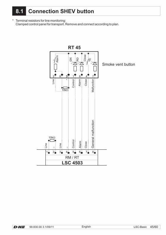
8.1 Connection SHEV button
*Clamped control panel for transport. Remove and connect according to plan.Terminal resistors for line monitoring:
45/6099.830.00 3.1/09/11 LSC-BasicEnglish
99.830.00 3.1/09/1146/60 LSC-Basic English
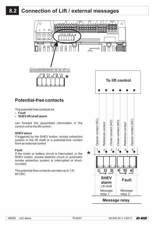
8.2
*
Potential-free contacts
The potential-free contacts for
can forward the assembled information in thecontrol unit to the lift control.
If triggered by the SHEV button, smoke extractionsystem in the lift shaft or a potential-free contactfrom an external control
If the motor or battery circuit is interrupted, or theSHEV button, smoke detector circuit or automaticsmoke extraction system is interrupted or short-circuited
The potential-free contacts can take up to 1A/60 VDC.
- Fault- SHEV lift shaft alarm
SHEV alarm
Fault
Connection of Lift / external messages
1 2 3 4 5 6
Message relay
To lift control
FaultSHEValarmLift shaft
Clo
ser
conta
ct(N
O)
Clo
ser
conta
ct(N
O)
Refe
rence
conta
ct
Refe
rence
conta
ct
Opener
conta
ct(N
C)
Opener
conta
ct(N
C)
Messagerelay 1
Messagerelay 2
*
*
47/6099.830.00 3.1/09/11 LSC-BasicEnglish
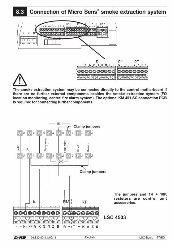
X.x8.3 Connection of Micro Sens smoke extraction system®
LSC 4503
*
Re
set+
Re
set
-
0V
1a
2a
3a
4a
5a
6a
7a
8a
1b
2b 3b
4b
5b
6b
7b
8b
+2
4V
Ala
rmre
lay
Fa
ult
rela
y
1K
10K
E RTRM
R T K A Z S
The jumpers and 1K + 10Kresistors are control unitaccessories.
The smoke extraction system may be connected directly to the control motherboard ifthere are no further external components besides the smoke extraction system (FOlocation monitoring, central fire alarm system). The optional KM 45 LSC connection PCBis required for connecting further components.
Clamp jumpers
Clamp jumpers
99.830.00 3.1/09/1148/60 LSC-Basic English
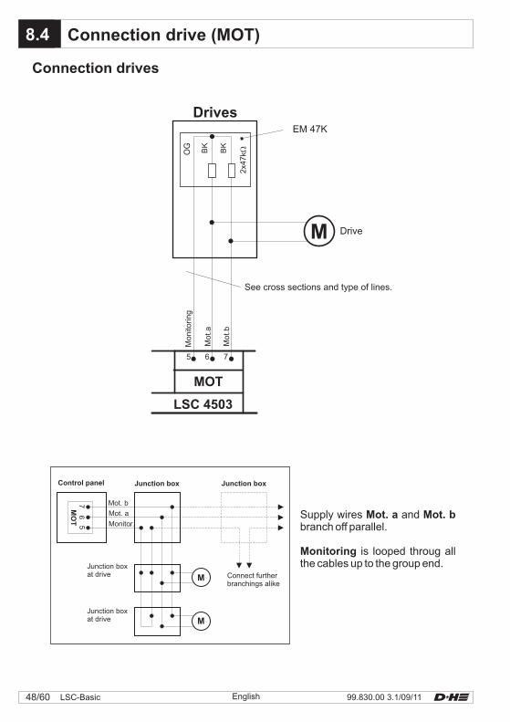
Connection drives
X.x8.4 Connection drive (MOT)
LSC 4503
Drives
See cross sections and type of lines.
Mo
nito
rin
g
Mo
t.a
Mo
t.b
5 6 7
MOT
BK
BK
OG
2x4
7k�
EM 47K
Drive
MO
T
Control panel
Mot. b76
5
Mot. a
Monitor..
M
M
Junction boxat drive Connect further
branchings alike
Junction box
Supply wires andbranch off parallel.
is looped throug allthe cables up to the group end.
Mot. a Mot. b
Monitoring
Junction box
Junction boxat drive
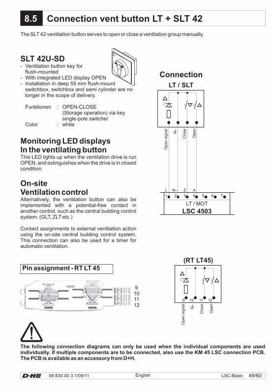
49/6099.830.00 3.1/09/11 LSC-BasicEnglish
8.5
Connection
SLT 42U-SD- Ventilation button key for
flush-mounted- With integrated LED display OPEN- Installation in deep 55 mm flush-mount
switchbox, switchbox and semi cylinder are nolonger in the scope of delivery.
Funktionen : OPEN-CLOSE(Storage operation) via keysingle-pole switcher
Color : white
Monitoring LED displaysIn the ventilating buttonThis LED lights up when the ventilation drive is runOPEN, and extinguishes when the drive is in closedcondition.
On-siteVentilation controlAlternatively, the ventilation button can also beimplemented with a potential-free contact inanother control, such as the central building controlsystem. (GLT, ZLT etc.)
Contact assignments to external ventilation actionusing the on-site central building control system.This connection can also be used for a timer forautomatic ventilation.
The SLT 42 ventilation button serves to open or close a ventilation group manually.
The following connection diagrams can only be used when the individual components are usedindividually. If multiple components are to be connected, also use the KM 45 LSC connection PCB.The PCB is available as an accessory from D+H.
Connection vent button LT + SLT 42
N–
Open
signal
Clo
se
9 10 11 12
Open
(RT LT45)Pin assignment - RT LT 45
9101112
N–
Open
signal
Clo
se
Open
LT / SLT
1 2 3 4 5
L
6
N–
7
Z A
LT / MOT
LSC 4503
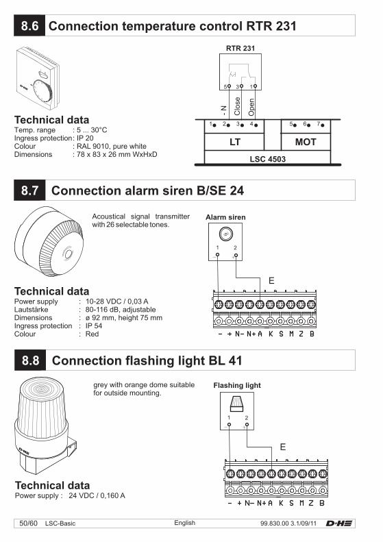
X.x8.6
LSC 4503
5 6 71 2 3 4
LT MOT
Open
Clo
se
-N
Technical dataTemp. range : 5 ... 30°CIngress protection
Dimensions : 78 x 83 x 26 mm WxHxD
: IP 20Colour : RAL 9010, pure white
Connection temperature control RTR 231
X.x8.8
8.x8.7
1 2
Connection flashing light BL 41
grey with orange dome suitablefor outside mounting.
Connection alarm siren B/SE 24
Acoustical signal transmitterwith 26 selectable tones.
Technical dataPower supply : 10-28 VDC / 0,03 ALautstärke : 80-116 dB, adjustableDimensions : ø 92 mm, height 75 mmIngress protection : IP 54Colour : Red
Technical dataPower supply : 24 VDC / 0,160 A
Flashing light
Alarm siren
E
E
1 2
99.830.00 3.1/09/1150/60 LSC-Basic English
RTR 231
5 3 1
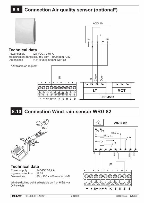
51/6099.830.00 3.1/09/11 LSC-BasicEnglish
* Available on request
8.9 Connection Air quality sensor (optional*)
Technical dataPower supply :24 VDC / 0,01 AMeasurement range:ca. 350 ppm - 3000 ppm (Co2)Dimensions :154 x 98 x 39 mm WxHxD
E
LSC 4503
5 6 71 2 3 4
LT MOT
Op
en
-N Clo
se
X.x8.10 Connection Wind-rain-sensor WRG 82
Technical dataPower supply : 24 VDC / 0,2 AIngress protection : IP 65Dimensions : 85 x 150 x 400 mm WxHxD
Wind-switching point adjustable on 4 or 6 Bft. viaDIP-switch
N- N+
AQS 10
E
-N +N
Rain
Win
d
1 2 4 3 5 7 6 8 9
R
W
WRG 82
S1 /1S1 /2
P3 P4
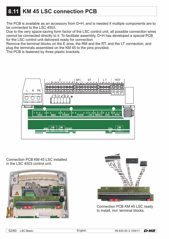
99.830.00 3.1/09/1152/60 LSC-Basic English
The PCB is available as an accessory from D+H, and is needed if multiple components are tobe connected to the LSC 4503.Due to the very space-saving form factor of the LSC control unit, all possible connection wirescannot be connected directly to it. To facilitate assembly, D+H has developed a special PCBfor the LSC control unit delivered ready for connection.Remove the terminal blocks on the E area, the RM and the RT, and the LT connection, andplug the terminals assembled on the KM 45 to the pins provided.The PCB is fastened by three plastic brackets.
X.x8.11 KM 45 LSC connection PCB
*
CO2CO2WRGASFO/HEFO/SÜBMZRAS RTR
ZN+
NSSSSRRRRB- - - - - - -- ---
RRKRN+ A NN N+
N Z A
S2FO/SÜ
S1BMZ
S3CO2CO2
Connection PCB KM 45 LSC installedin the LSC 4503 control unit.
Connection PCB KM 45 LSC readyto install, incl. terminal blocks.
Ala
rm
Stö
run
g7 2 8 3 6 4
RT45
Lin
ie
+K
on
tro
lle zu
+A
larm
-
1 5n
.c.
n.c.
X1
Mo
t.a
Mo
t.b
47k
47k
M
KA
K R>
R<
-> -< B ->- N->
N+
Z N->
A N-<
N+
N-
Z A
1 2 3 4 5 6
Pot. freier Wechsler
N-
a b
1 2 3 4 1 2 3
L Z A--
1 2 3 4 5 6 7 8
R T K A Z S
E
N-
N+
A K S M Z+ B-
+2
4V
1a
1b
0V
2a
2b
3a
3b
Ala
rmre
lais
4a
4b
5a
5b
6a
6b
+R
ese
t
7a
7b
-Re
set
8a
8b
10k
1k
1 2 3 4 5 6 7 8 9 10
E
RM RT LT MOT
1 2 4 5 3
WRG82
-N +N
S1/1
7 8 6
S1/2
9
P4P3
5 3 1
-
RTR230
RAS
KM 45 LSC
2 7
5
4
FO1362
-<R<
1k
Alarm Reset
-
RN-
+ R>
LSC 4503
BMZ FO/SÜ WRG CO2 RTR
bl
br
Üb
erw
.
sw
sw
or
Re
ge
n
Win
d
Regen
Wind
zu
au
f
Lin
ie
zu
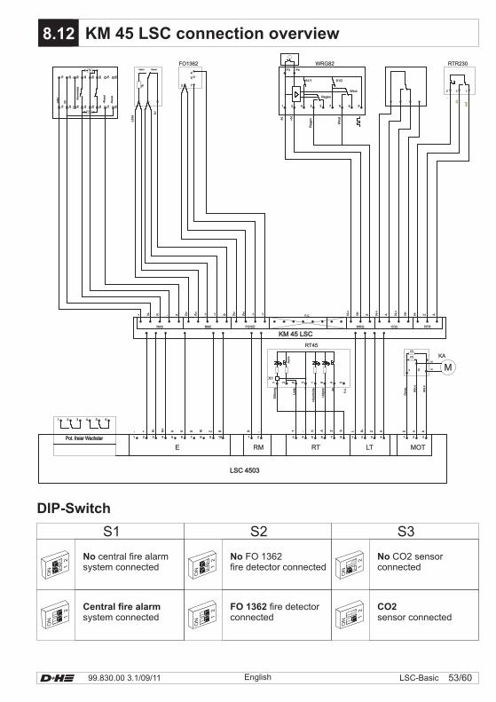
53/6099.830.00 3.1/09/11 LSC-BasicEnglish
CO2WRGASFO/HEFO/SÜBMZRAS RTR
ZN+
NSSSSRRRRB- - - - - - -- ---
RRKRN+ A NN N+
N Z A
S2FO/SÜ
S1BMZ
S3CO2
12
ON
12
ON
12
ON
X.x8.12 KM 45 LSC connection overview
Ala
rm
Stö
run
g7 2 8 3 6 4
RT45
Lin
ie
+K
on
tro
lle zu
+A
larm
-
1 5n
.c.
n.c.
X1
Mo
t.a
Mo
t.b
47k
47k
M
KA
K R>
R<
-> -< B ->- N->
N+
Z N->
A N-<
N+
N-
Z A
1 2 3 4 5 6
Pot. freier WechslerPot. freier Wechsler
N-
a b
1 2 3 4 1 2 3
L Z A--
1 2 3 4 5 6 7 8
R T K A Z S
E
N-
N+
A K S M Z+ B-
+2
4V
1a
1b
0V
2a
2b
3a
3b
Ala
rmre
lais
4a
4b
5a
5b
6a
6b
+R
ese
t
7a
7b
-Re
set
8a
8b
10k
1k
1 2 3 4 5 6 7 8 9 10
E
RM RT LT MOT
1 2 4 5 3
WRG82
-N +N
S1/1
7 8 6
S1/2
9
P4P3
5 3 1
-
RTR230
RAS
KM 45 LSCKM 45 LSC
2 7
5
4
FO1362
-<R<
1k
Alarm Reset
-
RN-
+ R>
LSC 4503LSC 4503
BMZ FO/SÜ WRG CO2 RTR
bl
br
Üb
erw
.
sw
sw
or
Re
ge
n
Win
d
Regen
Wind
zu
au
f
Lin
ie
zu
DIP-Switch
S1 S2 S3
No central fire alarmsystem connected
Central fire alarmsystem connected
No FO 1362fire detector connected
FO 1362 fire detectorconnected
CO2sensor connected1
2
ON
12
ON
12
ON
No CO2 sensorconnected
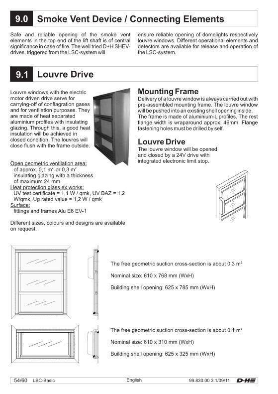
99.830.00 3.1/09/1154/60 LSC-Basic
X.x9.1
9.0
LSC
Nominal size: 610 x 768 mm (WxH)
Building shell opening: 625 x 785 mm (WxH)
The free geometric suction cross-section is about 0.3 m²
English
Louvre windows with the electricmotor driven drive serve forcarrying-off of conflagration gasesand for ventilation purposes. Theyare made of heat separatedaluminium profiles with insulatingglazing. Through this, a good heatinsulation will be achieved inclosed condition. The louvres willclose flush with the frame outside.
Open geometric ventilation area:
Heat protection glass ex works:
Surface:
of approx. 0,1 m or 0,3 minsulating glazing with a thicknessof maximum 24 mm.
UV test certificate = 1,1 W / qmk, UV BAZ = 1,2W/qmk, Ug rated value = 1,2 W / qmk
fittings and frames Alu E6 EV-1
Different sizes, colours and designs are availableon request.
2 2
Mounting FrameDelivery of a louvre window is always carried out withpre-assembled mounting frame. The louvre windowwill be pushed into an existing shell opening inside.The frame is made of aluminium-L profiles. The restflange width is wraparound approx. 46mm. Flangefastening holes must be drilled by self.
The louvre window will be openedand closed by a 24V drive withintegrated electronic limit stop.
Louvre Drive
Louvre Drive
Smoke Vent Device / Connecting Elements
Safe and reliable opening of the smoke ventelements in the top end of the lift shaft is of centralsignificance in case of fire. The well tried D+H SHEV-drives, triggered from the LSC-system will
ensure reliable opening of domelights respectivelylouvre windows. Different operational elements anddetectors are available for release and operation ofthe LSC-system.
Nominal size: 610 x 310 mm (WxH)
Building shell opening: 625 x 325 mm (WxH)
The free geometric suction cross-section is about 0.1 m²
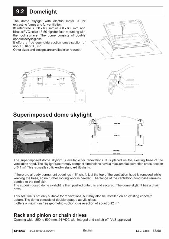
55/6099.830.00 3.1/09/11 LSC-Basic
The dome skylight with electric motor is forextracting fumes and for ventilation.Its rated size is 600 x 600 mm or 900 x 600 mm, andit has a PVC collar 15-50 high for flush mounting withthe roof surface. The dome consists of doubleopaque acrylic glass.It offers a free geometric suction cross-section ofabout 0.18 or 0.3 m².Other sizes and designs are available on request.
9.x9.2 Domelight
Superimposed dome skylight
Rack and pinion or chain drivesOpening width 350 to 500 mm, 24 VDC with integral end switch-off, VdS-approved
The superimposed dome skylight is available for renovations. It is placed on the existing base of theventilation hood. The skylight's extremely compact dimensions have a max. smoke extraction cross-sectionof 0.1 m². This is usually sufficient for standard lift shafts.
If there are already permanent openings in lift shaft, just the top of the ventilation hood is removed whilekeeping the base, so no further roofing work is needed. The flange of the ventilation hood base remainsbonded to the roof skin.The superimposed dome skylight is then pushed onto this and secured. The dome skylight has a chaindrive.
This solution is not only suitable for renovations, but may also be installed on an existing concreteupturn. The dome consists of double opaque acrylic glass.It offers a maximum free geometric suction cross-section of about 0.12 m².
English
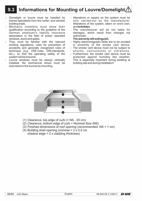
X.x9.3 Informations for Mounting of Louvre/Domelight
(1) Clearance, top edge of curb (= NS - 20 cm)(2) Clearance, bottom edge of curb = Nominal Size (NS)(3) Finished dimensions of roof opening (recommended: NS + 1 cm)(4) Building shell opening (nominal + 2 x 0.5 cm
shadow edge + 2 x cladding thickness)
- Domelight or louvre must be handled bytrained specialists from the roofer- and windowbuilding trade.
- Mechanic instal lers must show theirqualification according to the guideline of theGerman employer's liability insuranceassociation in the field of power operatedwindows, doors and gates.
- They must be familiar with the relevantworking regulations, rules for prevention ofaccidents and generally recognized rules oftechnique (e.g. VDE-rules, DIN-standards,etc.), so that the operating safety of thesystem will be ensured.
- Louvre windows must be always verticallyinstalled. No mechanical stress must beexercised on the louvres by mounting.
- Alterations or repairs on the system must beonly carried-out by the manufacturer.Alterations of the system, taken on one's own,are .The manufacturer will be not liable fordamages, which result from changes notauthorized.
- Highly electromagnetic fields are to be avoidedin proximity of the smoke vent device.
- The smoke vent device must not be subject tos h o c k s , c o n c u s s i o n s o r v i b r a t i o n s .
- Furthermore, the smoke vent device must beprotected against humidity like weather.This is especially important during bedding atbuilding site and during installation!
forbidden
The warranty will extinguish.
99.830.00 3.1/09/1156/60 LSC-Basic English

aaaaaaaaaaaaaaaaaaaaaaaaaaaaaaaaaaaaaaaaaaaaaaaaaaaaaaaaaaaaaaaaaaaaaaaaaaaaaaaaaaaaaaaaaaaaaaaaaaaaaaaaaaaaaaaaaaaaaaaaaaaaaaaaaaaaaaaaaaaaaaaaaaaaaaaaaaaaaaaaaaaaaaaaaaaaaaaaaaaaaaaaaaaaaaaaaaaaaaaaaaaaaaaaaaaaaaaaaaaaaaaaaaaaaaaaaaaaaaaaaaaaaaaaaaaaaaaaaaaaaaaaaaaaaaaaaaaaaaaaaaaaaaaaaaaaaaaaaaaaaaaaaaaaaaaaaaaaaaaaaaaaaaaaaaaaaaaaaaaaaaaaaaaaaaaaaaaaaaaaaaaaaaaaaaaaaaaaaaaaaaaaaaaaaaaaaaaaaaaaaaaaaaaaaaaaaaaaaaaaaaaaaaaaaaaaaaaaaaaaaaaaaaaaaaaaaaaaaaaaaaaaaaaaaaaaaaaaaaaaaaaaaaaaaaaaaaaaaaaaaaaaaaaaaaaaaaaaaaaaaaaaaaaaaaaaaaaaaaaaaaaaaaaaaaaaaaaaaaaaaaaaaaaaaaaaaaaaaaaaaaaaaaaaaaaaaaaaaaaaaaaaaaaaa
Notes
English 57/6099.830.00 3.1/09/11 LSC-Basic
English 99.830.00 3.1/09/1158/60 LSC-Basic
aaaaaaaaaaaaaaaaaaaaaaaaaaaaaaaaaaaaaaaaaaaaaaaaaaaaaaaaaaaaaaaaaaaaaaaaaaaaaaaaaaaaaaaaaaaaaaaaaaaaaaaaaaaaaaaaaaaaaaaaaaaaaaaaaaaaaaaaaaaaaaaaaaaaaaaaaaaaaaaaaaaaaaaaaaaaaaaaaaaaaaaaaaaaaaaaaaaaaaaaaaaaaaaaaaaaaaaaaaaaaaaaaaaaaaaaaaaaaaaaaaaaaaaaaaaaaaaaaaaaaaaaaaaaaaaaaaaaaaaaaaaaaaaaaaaaaaaaaaaaaaaaaaaaaaaaaaaaaaaaaaaaaaaaaaaaaaaaaaaaaaaaaaaaaaaaaaaaaaaaaaaaaaaaaaaaaaaaaaaaaaaaaaaaaaaaaaaaaaaaaaaaaaaaaaaaaaaaaaaaaaaaaaaaaaaaaaaaaaaaaaaaaaaaaaaaaaaaaaaaaaaaaaaaaaaaaaaaaaaaaaaaaaaaaaaaaaaaaaaaaaaaaaaaaaaaaaaaaaaaaaaaaaaaaaaaaaaaaaaaaaaaaaaaaaaaaaaaaaaaaaaaaaaaaaaaaaaaaaaaaaaaaaaaaaaaaaaaaaaaaaaaaaaaa
Notes

English 59/6099.830.00 3.1/09/11 LSC-Basic
aaaaaaaaaaaaaaaaaaaaaaaaaaaaaaaaaaaaaaaaaaaaaaaaaaaaaaaaaaaaaaaaaaaaaaaaaaaaaaaaaaaaaaaaaaaaaaaaaaaaaaaaaaaaaaaaaaaaaaaaaaaaaaaaaaaaaaaaaaaaaaaaaaaaaaaaaaaaaaaaaaaaaaaaaaaaaaaaaaaaaaaaaaaaaaaaaaaaaaaaaaaaaaaaaaaaaaaaaaaaaaaaaaaaaaaaaaaaaaaaaaaaaaaaaaaaaaaaaaaaaaaaaaaaaaaaaaaaaaaaaaaaaaaaaaaaaaaaaaaaaaaaaaaaaaaaaaaaaaaaaaaaaaaaaaaaaaaaaaaaaaaaaaaaaaaaaaaaaaaaaaaaaaaaaaaaaaaaaaaaaaaaaaaaaaaaaaaaaaaaaaaaaaaaaaaaaaaaaaaaaaaaaaaaaaaaaaaaaaaaaaaaaaaaaaaaaaaaaaaaaaaaaaaaaaaaaaaaaaaaaaaaaaaaaaaaaaaaaaaaaaaaaaaaaaaaaaaaaaaaaaaaaaaaaaaaaaaaaaaaaaaaaaaaaaaaaaaaaaaaaaaaaaaaaaaaaaaaaaaaaaaaaaaaaaaaaaaaaaaaaaaaaaaaa
Notes
D+H Mechatronic AG, Georg-Sasse-Straße 28-32, D-22949 AmmersbekTelefon: +49 40 605 65-0, Fax: +49 40 605 65-222Internet: www.lsc.dh-partner.com, E-Mail: [email protected] © 2010 D+H Mechatronic AG, Ammersbek
Consulting • Service • Sales
D+H is a member of the following associations:
99
.83
0.0
03
.1/0
9/1
1
![Smoke extraction and ventilation system for lift shafts · PDF fileAccording to the Model Building Code (MBO) ... according to EN 54-7 LIFT BEAM [- 4.2 -] Motorised linear smoke detector](https://img.pdfslide.us/doc/110x75/5a788b6f7f8b9a77438e9742/smoke-extraction-and-ventilation-system-for-lift-shafts-to-the-model-building-code.jpg)