Embed Size (px)
Citation preview
LS2 Dry Sleeve KitInstallation Guide

Thank you for purchasing the Darton state of the art newGM™ LS-2 Dry Sleeve Kit. The kit makes possible max-imum bore sizes, increased cylinder strength and superi-or wear resistance.
Darton wants to provide you with the best technical infor-mation we have available to ensure that your sleevedengine will perform to your expectations. Therefore, wehave formulated a program of required procedures andcomponents, which we believe will ensure operating suc-cess of your sleeved engine in whatever application it willsee service in.

INSTALLATION PROCEDURESRevised 5-15-06
LS2 Dry Sleeve Kit InstallationRead and make sure you understand these instruction beforeproceeding with block machining. If you have questions con-cerning machining, assembly, proper tooling, machines, etc.
call sales at Darton.
Preparation, Fixturing:
1. The block needs to be fully stripped, cleaned and inspected beforemachining. Main web cracks, or structural damage will prevent satisfac-tory sleeve installation.
2. Brand new blocks must be vibratory stress relieved prior to blockmachining. Failure to do this will result in out of round cylinder boresafter the engine is fired up.
Setup and Block Machining:
1. With your block mounting fixture securely bolted to the CNC machinetable, indicate the centerline of your block mounting bar in the “Y” axisdirection. That will be your “Y” fixture or part offset depending on ter-minology used with your machine. You will only have to do this onetime since this position will remain the same. The object is to correctfor factory machining errors, block warpage. You want the dry linersinstalled directly over the crankshaft axis and not offset as would prob-ably happen if you merely went off the existing cylinder centerline.
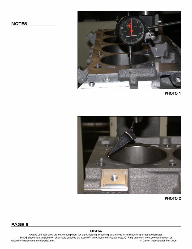
Now set the block up on the CNC machine. The preferred method iswith precision made mounting rings located in the front and rear mainbearing bores and with the bell housing face securely bolted to a fix-ture plate. Rotate your fixture so the left (driver’s side bank) is facingup. Indicate the rear deck surface of the block (by the bell housing) -photo 1. Rotate the block around the crank axis until you get close tozero run out across the deck from side to side. Lock your fixture whenyou are satisfied the block is true. Zero the degree wheel if soequipped. Note that most blocks will be warped front to back. This iswhy I recommend dialing in the deck surface at the rear of the block.Now indicate the “X” centerline of cylinder number one, (left bank firstcylinder) - photo 2. The centerline position is your “X” fixture offsetposition. Enter the “X” and “Y” offsets in your machine’s fixture or partoffset table.
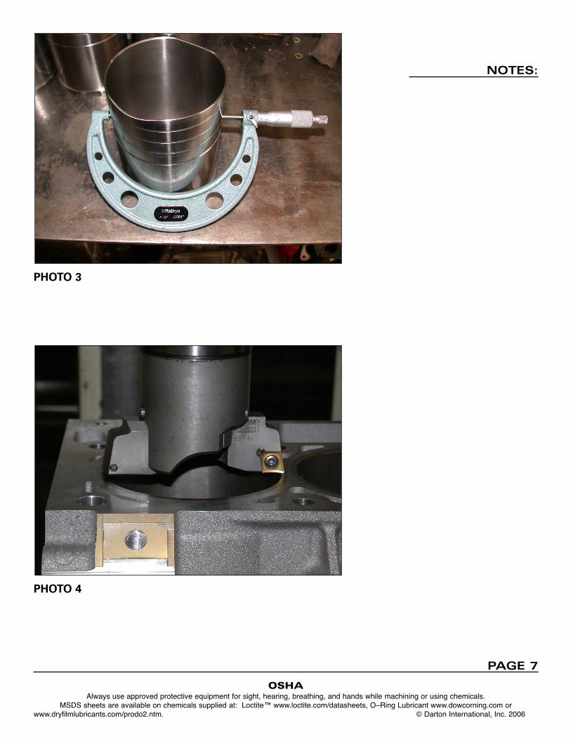
2. Clean the rust preventative from the sleeves using lacquer thinner.Measure the bottom diameter of each sleeve. Generally the diameterswill be very close - within .001” in any one set. Measure the diametersat 90 degrees and average the result - photo 3. The lower sleeve diam-
NOTES:
OSHAAlways use approved protective equipment for sight, hearing, breathing, and hands while machining or using chemicals.
MSDS sheets are available on chemicals supplied at: Loctite™ www.loctite.com/datasheets, O–Ring Lubricant www.dowcorning.com or www.dryfilmlubricants.com/prodo2.ntm. © Darton International, Inc. 2006
PAGE 2

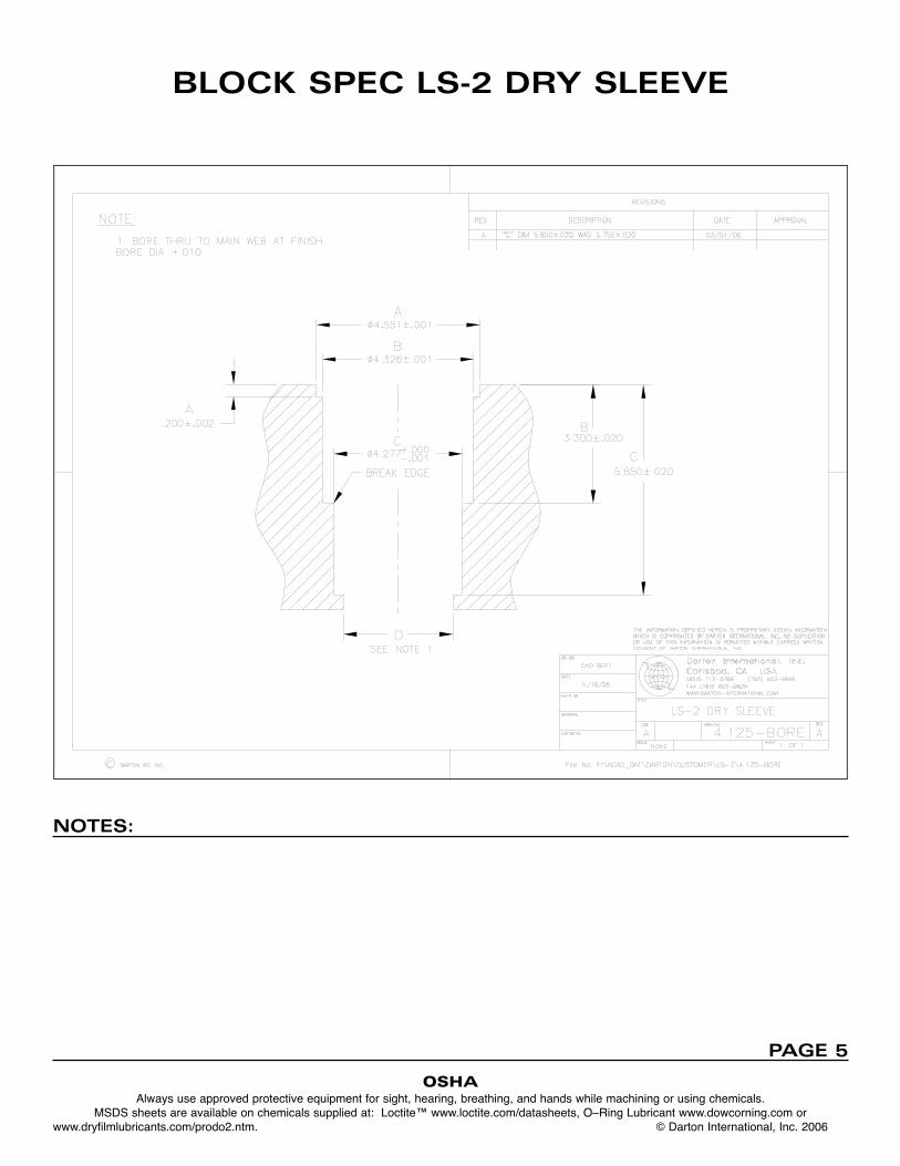
eter specification is 4.275”. The block is bored .0015” to .0017” larger
than the sleeve lower diameter. Do not attempt to install the sleeves ifyou can not hold this tolerance. Call Darton for info on proper toolingand or machines to ensure a satisfactory job. The upper body diameterhas a slight taper. Measure the diameter directly under the flange. Thisdiameter specification is 4.325”. Again, the block will be bored .0015”to .0017” larger than your measured diameter.
3. Touch off your tools on the deck surface at the front of the left bank eitherbefore you begin machining or as you are about to use them, whicheveryou prefer - photo 4. Set your tool length offsets into your machine’s tooltable. Machining depths are from the deck surface down.
4. Note that the bore center to center is 4.400”, same as a small blockChevy. You need to keep this centerline dimension to +-.0005”. Notethat in order to maintain the required tolerances it is highly advisableyou use a machine with flood coolant. It will be impossible to hold tol-erance otherwise and a poor job will be the result.
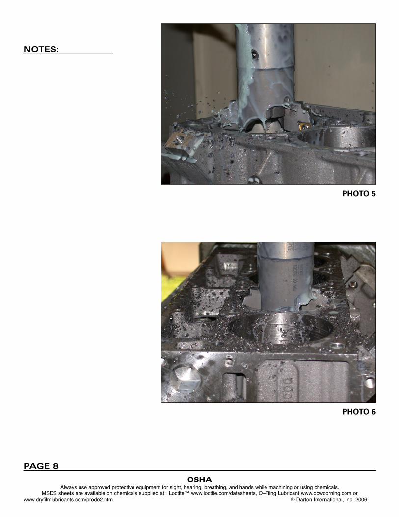
5. First operation is to bore the four cylinders on the left bank to 4.170”diameter to the main bearing webs. Use a double cutter boring headwith .030” radius inserts for this operation which will allow sizing in onepass - photos 5 and 6. Depth of cut is 6.250” from the deck surface.
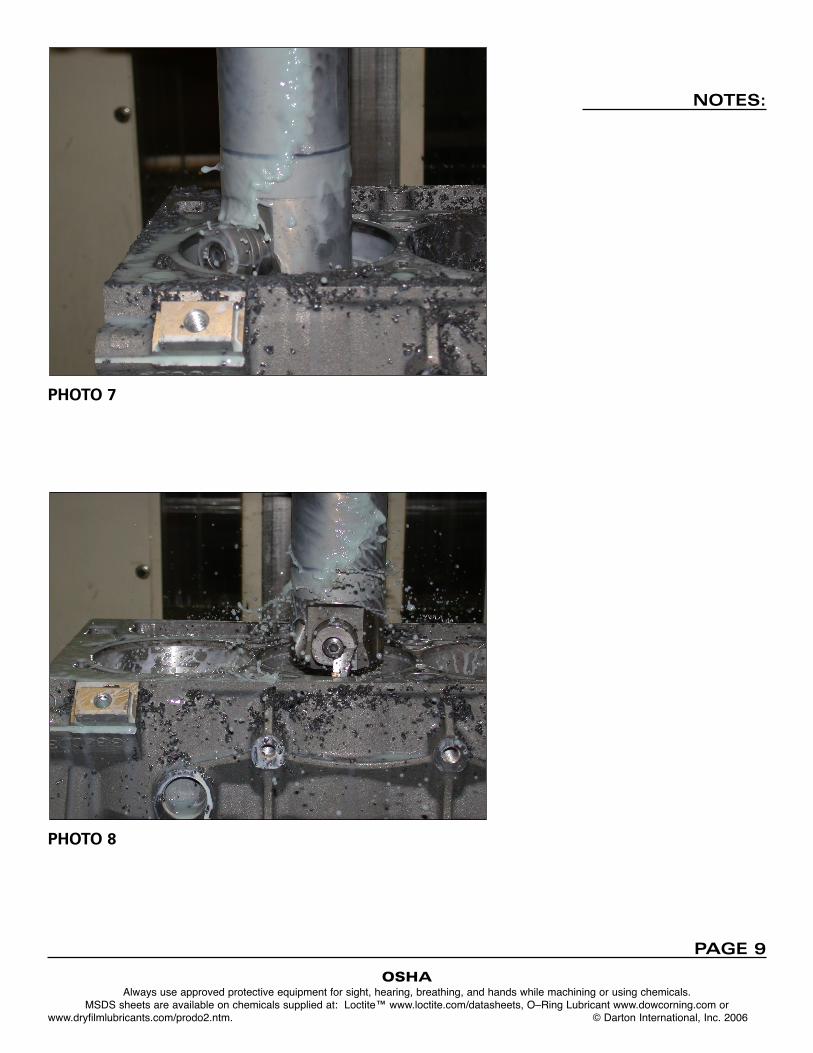
6. Next operation is boring for the lower body diameter. Bore larger thansleeve as instructed above. Depth of bore should be 5.850” to clean upthe casting at the bottom of the bore. Photos 7 and 8.
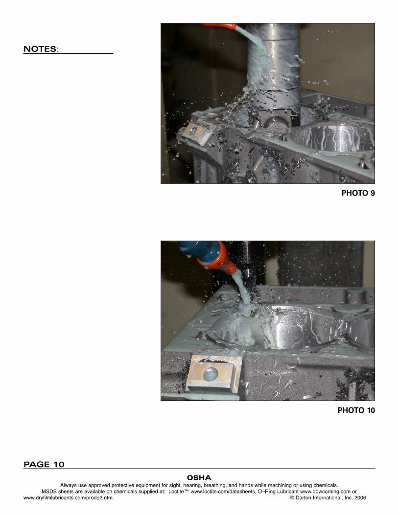
7. Next operation is boring for the upper body diameter. Again, bore larg-er than the measured sleeve diameter as instructed above. Machiningdepth should be 3.280” to 3.300”. Photo 9.
8. Next, machine the upper flange diameter to your measured diameter+.002”. The nominal diameter on the sleeve flange is 4.550”. Your flangebore should be 4.552” machined to a depth of .202”. You can bore oruse circular interpolation for this cut dependent on your tooling andexpertise. If you use circular interpolation with a carbide end mill, usetwo passes leaving ~ .010” for the finish pass. Photo 10. This willensure in a better surface finish and rounder hole.
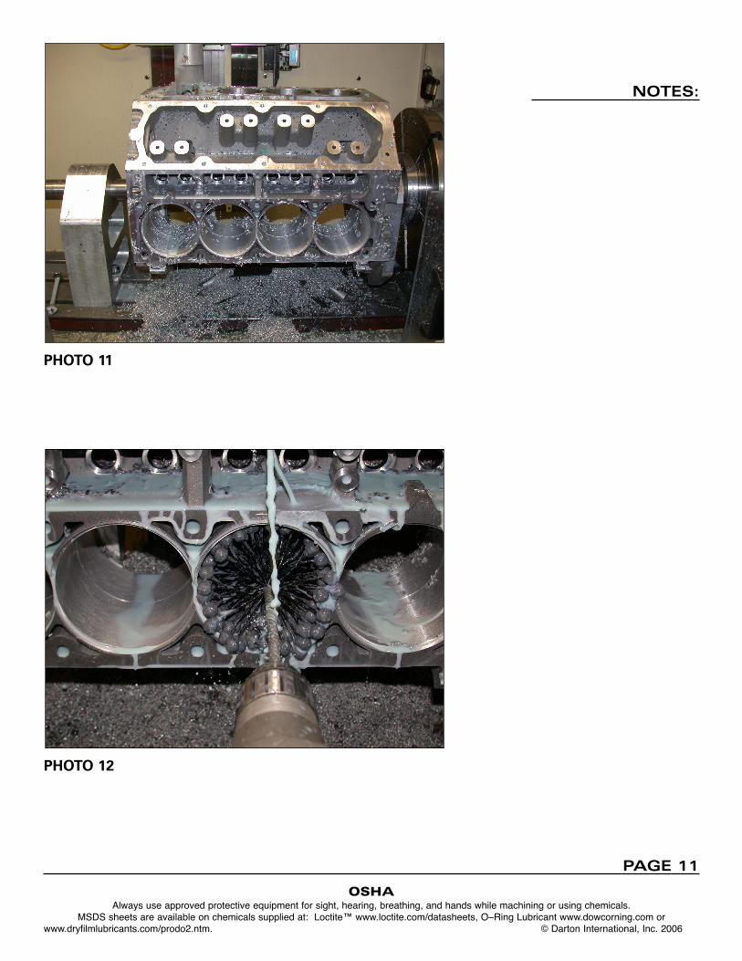
9. Repeat operations (5 through 8) on the opposite bank after indexing theblock 90 degrees. Note that the offset for cylinder two (front cylinder onthe right bank) is +.950” towards the rear of the block from cylinder oneon the left bank. Make certain to adjust your new “X” offset in themachine fixture or part offset table else you will ruin your block. Photo 11.
10. Prior to removing the block from the machine, run a ball hone throughall the bores. Remove the block, clean it, and deburr it. Make certainthe head threads are clean. A thread forming tool should be runthrough the head bolt holes on used blocks. Photo 12.
NOTES:
OSHAAlways use approved protective equipment for sight, hearing, breathing, and hands while machining or using chemicals.
MSDS sheets are available on chemicals supplied at: Loctite™ www.loctite.com/datasheets, O–Ring Lubricant www.dowcorning.com or www.dryfilmlubricants.com/prodo2.ntm. © Darton International, Inc. 2006
PAGE 3
Sleeve Installation:
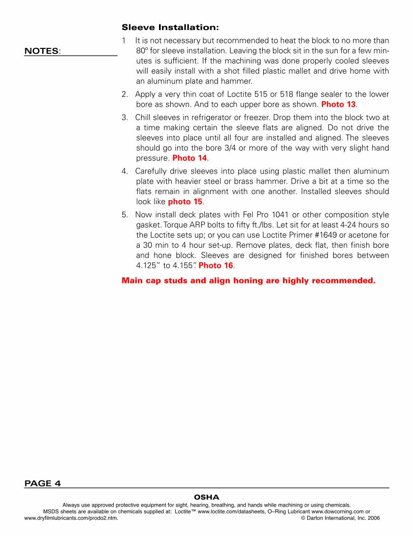
1 It is not necessary but recommended to heat the block to no more than80º for sleeve installation. Leaving the block sit in the sun for a few min-utes is sufficient. If the machining was done properly cooled sleeveswill easily install with a shot filled plastic mallet and drive home withan aluminum plate and hammer.
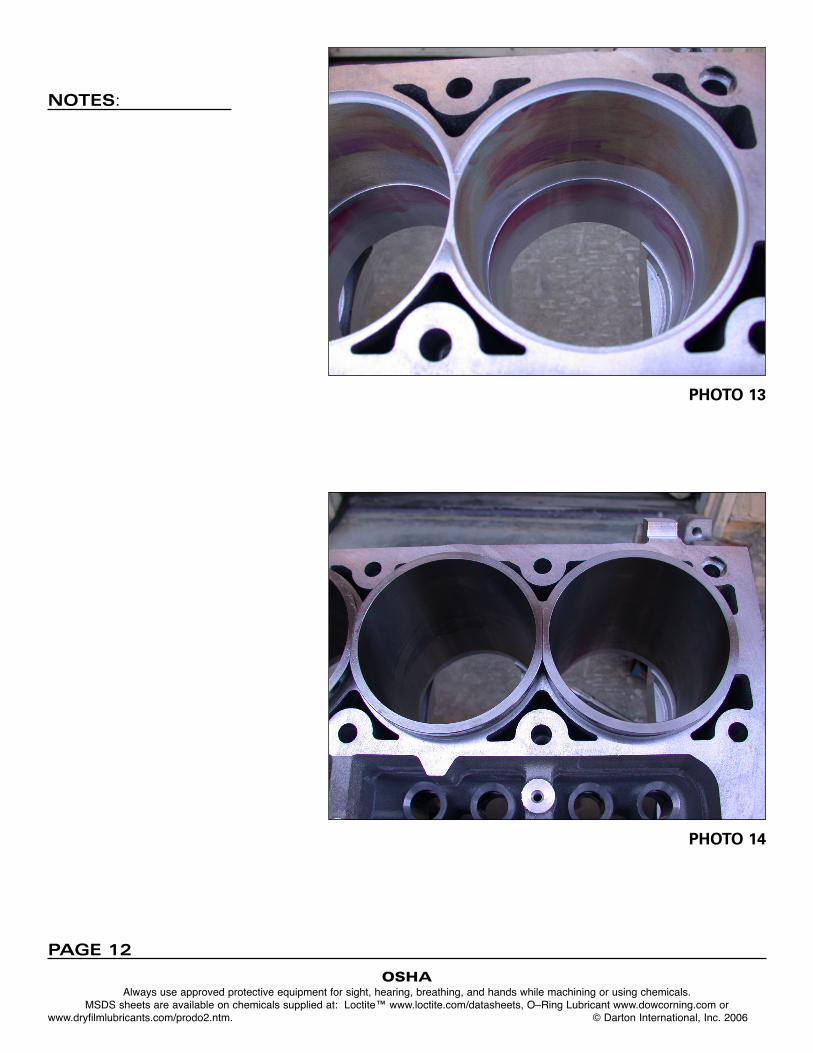
2. Apply a very thin coat of Loctite 515 or 518 flange sealer to the lowerbore as shown. And to each upper bore as shown. Photo 13.
3. Chill sleeves in refrigerator or freezer. Drop them into the block two ata time making certain the sleeve flats are aligned. Do not drive thesleeves into place until all four are installed and aligned. The sleevesshould go into the bore 3/4 or more of the way with very slight handpressure. Photo 14.
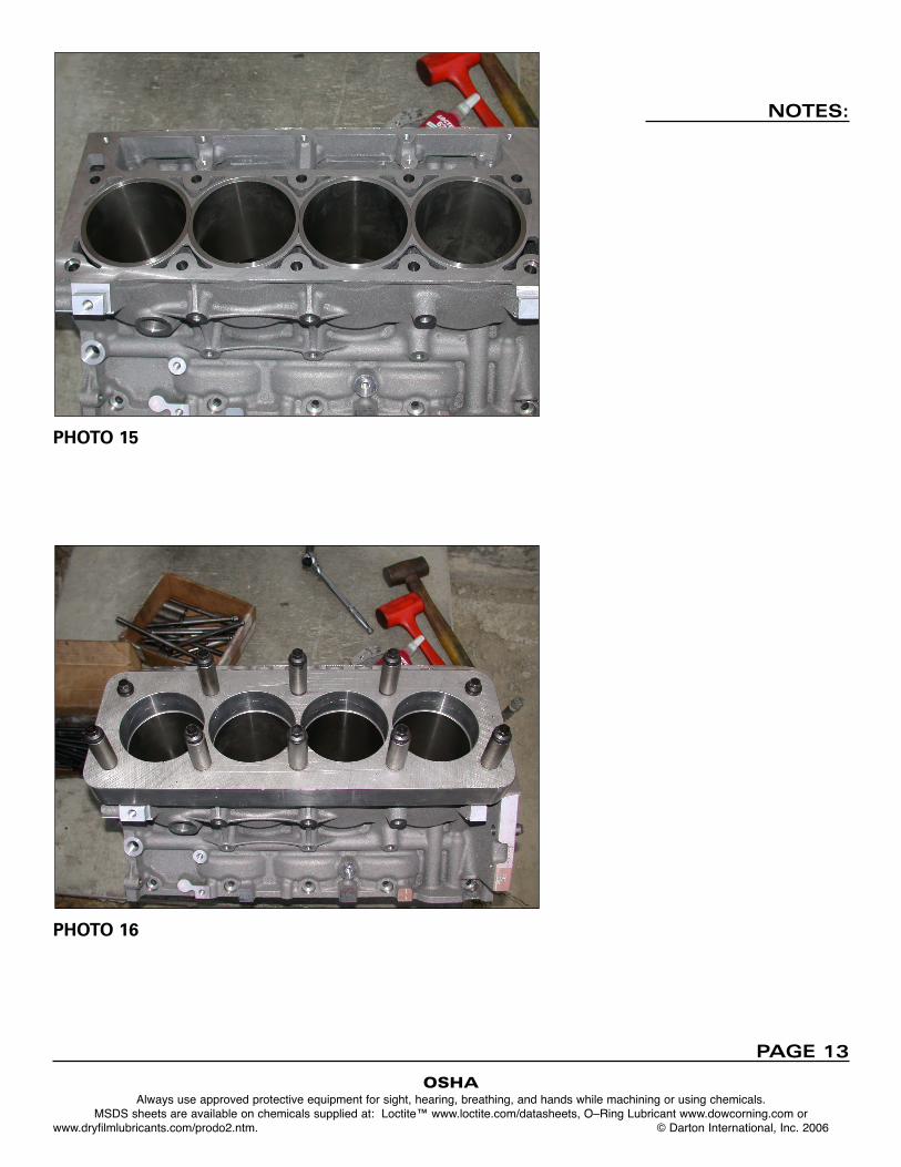
4. Carefully drive sleeves into place using plastic mallet then aluminumplate with heavier steel or brass hammer. Drive a bit at a time so theflats remain in alignment with one another. Installed sleeves shouldlook like photo 15.
5. Now install deck plates with Fel Pro 1041 or other composition stylegasket. Torque ARP bolts to fifty ft./lbs. Let sit for at least 4-24 hours sothe Loctite sets up; or you can use Loctite Primer #1649 or acetone fora 30 min to 4 hour set-up. Remove plates, deck flat, then finish boreand hone block. Sleeves are designed for finished bores between4.125” to 4.155”. Photo 16.
Main cap studs and align honing are highly recommended.
NOTES:
OSHAAlways use approved protective equipment for sight, hearing, breathing, and hands while machining or using chemicals.
MSDS sheets are available on chemicals supplied at: Loctite™ www.loctite.com/datasheets, O–Ring Lubricant www.dowcorning.com or www.dryfilmlubricants.com/prodo2.ntm. © Darton International, Inc. 2006
PAGE 4
OSHAAlways use approved protective equipment for sight, hearing, breathing, and hands while machining or using chemicals.
MSDS sheets are available on chemicals supplied at: Loctite™ www.loctite.com/datasheets, O–Ring Lubricant www.dowcorning.com or www.dryfilmlubricants.com/prodo2.ntm. © Darton International, Inc. 2006
NOTES:
BLOCK SPEC LS-2 DRY SLEEVE
PAGE 5
NOTES:
OSHAAlways use approved protective equipment for sight, hearing, breathing, and hands while machining or using chemicals.
MSDS sheets are available on chemicals supplied at: Loctite™ www.loctite.com/datasheets, O–Ring Lubricant www.dowcorning.com or www.dryfilmlubricants.com/prodo2.ntm. © Darton International, Inc. 2006
PHOTO 1
PHOTO 2
PAGE 6
NOTES:
OSHAAlways use approved protective equipment for sight, hearing, breathing, and hands while machining or using chemicals.
MSDS sheets are available on chemicals supplied at: Loctite™ www.loctite.com/datasheets, O–Ring Lubricant www.dowcorning.com or www.dryfilmlubricants.com/prodo2.ntm. © Darton International, Inc. 2006
PHOTO 3
PHOTO 4
PAGE 7
NOTES:
OSHAAlways use approved protective equipment for sight, hearing, breathing, and hands while machining or using chemicals.
MSDS sheets are available on chemicals supplied at: Loctite™ www.loctite.com/datasheets, O–Ring Lubricant www.dowcorning.com or www.dryfilmlubricants.com/prodo2.ntm. © Darton International, Inc. 2006
PHOTO 5
PHOTO 6
PAGE 8
NOTES:
OSHAAlways use approved protective equipment for sight, hearing, breathing, and hands while machining or using chemicals.
MSDS sheets are available on chemicals supplied at: Loctite™ www.loctite.com/datasheets, O–Ring Lubricant www.dowcorning.com or www.dryfilmlubricants.com/prodo2.ntm. © Darton International, Inc. 2006
PHOTO 7
PHOTO 8
PAGE 9
NOTES:
OSHAAlways use approved protective equipment for sight, hearing, breathing, and hands while machining or using chemicals.
MSDS sheets are available on chemicals supplied at: Loctite™ www.loctite.com/datasheets, O–Ring Lubricant www.dowcorning.com or www.dryfilmlubricants.com/prodo2.ntm. © Darton International, Inc. 2006
PHOTO 9
PHOTO 10
PAGE 10
NOTES:
OSHAAlways use approved protective equipment for sight, hearing, breathing, and hands while machining or using chemicals.
MSDS sheets are available on chemicals supplied at: Loctite™ www.loctite.com/datasheets, O–Ring Lubricant www.dowcorning.com or www.dryfilmlubricants.com/prodo2.ntm. © Darton International, Inc. 2006
PHOTO 11
PHOTO 12
PAGE 11
NOTES:
OSHAAlways use approved protective equipment for sight, hearing, breathing, and hands while machining or using chemicals.
MSDS sheets are available on chemicals supplied at: Loctite™ www.loctite.com/datasheets, O–Ring Lubricant www.dowcorning.com or www.dryfilmlubricants.com/prodo2.ntm. © Darton International, Inc. 2006
PHOTO 13
PHOTO 14
PAGE 12
NOTES:
OSHAAlways use approved protective equipment for sight, hearing, breathing, and hands while machining or using chemicals.
MSDS sheets are available on chemicals supplied at: Loctite™ www.loctite.com/datasheets, O–Ring Lubricant www.dowcorning.com or www.dryfilmlubricants.com/prodo2.ntm. © Darton International, Inc. 2006
PHOTO 15
PHOTO 16
PAGE 13
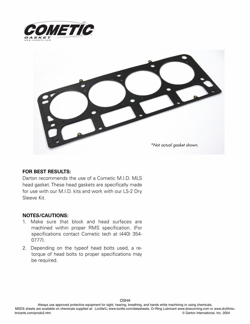
FOR BEST RESULTS:
Darton recommends the use of a Cometic M.I.D. MLShead gasket. These head gaskets are specifically madefor use with our M.I.D. kits and work with our LS-2 DrySleeve Kit.
NOTES/CAUTIONS:
1. Make sure that block and head surfaces aremachined within proper RMS specification. (Forspecifications contact Cometic tech at (440) 354-0777).
2. Depending on the typeof head bolts used, a re-torque of head bolts to proper specifications maybe required.
*Not actual gasket shown.
OSHAAlways use approved protective equipment for sight, hearing, breathing, and hands while machining or using chemicals.
MSDS sheets are available on chemicals supplied at: Loctite‰ www.loctite.com/datasheets, O–Ring Lubricant www.dowcorning.com or www.dryfilmlu-bricants.com/prodo2.ntm. © Darton International, Inc. 2004
Darton recommends theuse of Evans coolant!
MPG+ for all street applications.
MPGR for full race applications.
OSHAAlways use approved protective equipment for sight, hearing, breathing, and hands while machining or using chemicals.
MSDS sheets are available on chemicals supplied at: Loctite‰ www.loctite.com/datasheets, O–Ring Lubricant www.dowcorning.com or www.dryfilmlu-bricants.com/prodo2.ntm. © Darton International, Inc. 2004
PRODUCTS
®
PR
EC
IS
IO
N
EN
GI
NE
R
EB
UI
LD
IN
G
EQ
UI
PM
EN
T
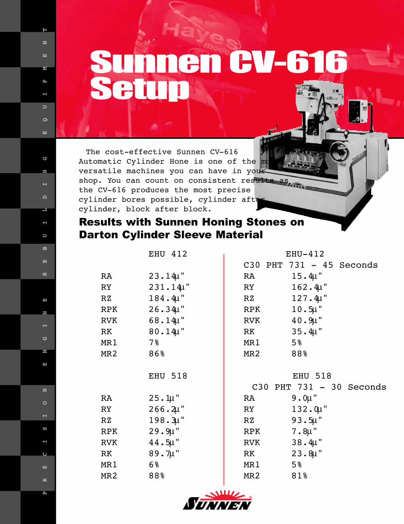
Sunnen CV-616Setup
EHU 412 EHU-412C30 PHT 731 - 45 Seconds
RA 23.14 μ" RA 15.4 μ"RY 231.14 μ" RY 162.4 μ"RZ 184.4 μ" RZ 127.4 μ"RPK 26.34 μ" RPK 10.5 μ"RVK 68.14 μ" RVK 40.9 μ"RK 80.14 μ" RK 35.4 μ"MR1 7% MR1 5%MR2 86% MR2 88%
EHU 518 EHU 518C30 PHT 731 - 30 Seconds
RA 25.1 μ" RA 9.0 μ"RY 266.2 μ" RY 132.0 μ"RZ 198.3 μ" RZ 93.5 μ"RPK 29.9 μ" RPK 7.8 μ"RVK 44.5 μ" RVK 38.4 μ"RK 89.7 μ" RK 23.8 μ"MR1 6% MR1 5%MR2 88% MR2 81%
Results with Sunnen Honing Stones onDarton Cylinder Sleeve Material
The cost-effective Sunnen CV-616Automatic Cylinder Hone is one of the mostversatile machines you can have in yourshop. You can count on consistent results asthe CV-616 produces the most precise cylinder bores possible, cylinder after cylinder, block after block.
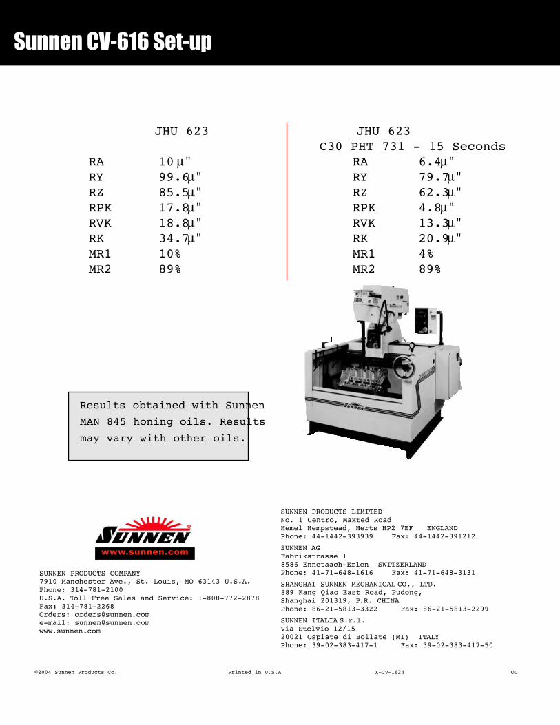
Sunnen CV-616 Set-up
JHU 623 JHU 623C30 PHT 731 - 15 Seconds
RA 10 μ" RA 6.4 μ"RY 99.6 μ" RY 79.7 μ"RZ 85.5 μ" RZ 62.3 μ"RPK 17.8 μ" RPK 4.8 μ"RVK 18.8 μ" RVK 13.3 μ"RK 34.7 μ" RK 20.9 μ"MR1 10% MR1 4%MR2 89% MR2 89%
Results obtained with Sunnen
MAN 845 honing oils. Results
may vary with other oils.
SUNNEN PRODUCTS COMPANY7910 Manchester Ave., St. Louis, MO 63143 U.S.A.Phone: 314-781-2100U.S.A. Toll Free Sales and Service: 1-800-772-2878Fax: 314-781-2268Orders: [email protected]: [email protected]
SUNNEN PRODUCTS LIMITEDNo. 1 Centro, Maxted RoadHemel Hempstead, Herts HP2 7EF ENGLANDPhone: 44-1442-393939 Fax: 44-1442-391212
SUNNEN AGFabrikstrasse 18586 Ennetaach-Erlen SWITZERLANDPhone: 41-71-648-1616 Fax: 41-71-648-3131
SHANGHAI SUNNEN MECHANICAL CO., LTD.889 Kang Qiao East Road, Pudong, Shanghai 201319, P.R. CHINAPhone: 86-21-5813-3322 Fax: 86-21-5813-2299
SUNNEN ITALIA S.r.l.Via Stelvio 12/1520021 Ospiate di Bollate (MI) ITALYPhone: 39-02-383-417-1 Fax: 39-02-383-417-50
www.sunnen.com
©2004 Sunnen Products Co. Printed in U.S.A X-CV-1624 OD


![Duraflow, ls2 & ergo tilt [mar 13]](https://img.pdfslide.us/doc/110x75/554b894cb4c90561588b53b8/duraflow-ls2-ergo-tilt-mar-13.jpg)