Embed Size (px)
Citation preview
506390-01 Issue 1728 Page 1 of 11
Save these instructions for future reference
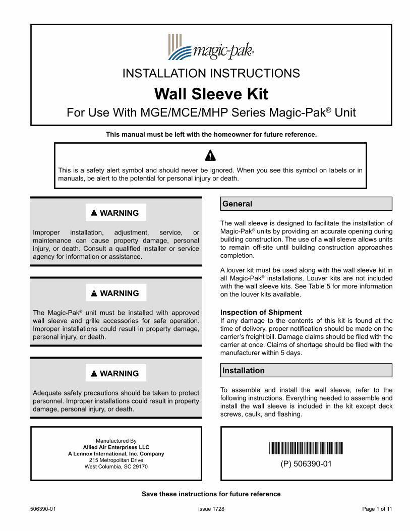
INSTALLATION INSTRUCTIONS
Wall Sleeve KitFor Use With MGE/MCE/MHP Series Magic-Pak® Unit
Manufactured ByAllied Air Enterprises LLC
A Lennox International, Inc. Company215 Metropolitan Drive
West Columbia, SC 29170
This manual must be left with the homeowner for future reference.
This is a safety alert symbol and should never be ignored. When you see this symbol on labels or in manuals, be alert to the potential for personal injury or death.
(P) 506390-01*P506390-01*
WARNING
Improper installation, adjustment, service, or maintenance can cause property damage, personal injury, or death. Consult a qualified installer or service agency for information or assistance.
WARNING
The Magic-Pak® unit must be installed with approved wall sleeve and grille accessories for safe operation. Improper installations could result in property damage, personal injury, or death.
WARNING
Adequate safety precautions should be taken to protect personnel. Improper installations could result in property damage, personal injury, or death.
General
The wall sleeve is designed to facilitate the installation of Magic-Pak® units by providing an accurate opening during building construction. The use of a wall sleeve allows units to remain off-site until building construction approaches completion.
A louver kit must be used along with the wall sleeve kit in all Magic-Pak® installations. Louver kits are not included with the wall sleeve kits. See Table 5 for more information on the louver kits available.
Inspection of ShipmentIf any damage to the contents of this kit is found at the time of delivery, proper notification should be made on the carrier’s freight bill. Damage claims should be filed with the carrier at once. Claims of shortage should be filed with the manufacturer within 5 days.
Installation
To assemble and install the wall sleeve, refer to the following instructions. Everything needed to assemble and install the wall sleeve is included in the kit except deck screws, caulk, and flashing.

506390-01Issue 1728Page 2 of 11
Installation Preparation1. Inspect the wall opening. Make sure that it is the
proper size (see the Required Wall Opening drawing on Page 10).
2. Before the wall sleeve can be installed, a platform must be built to support the Magic-Pak® unit. The platform may be constructed of plywood and 2 x 4’s.
Recommended Height of Platform: The platform must be made level to the sill plate of the wall opening (Figure 1). Minimum height of platform is 4”.
Figure 1. Platform Assembly
30" Minimum
Platform
4" Minimum
Floor
Sill Plate
RecommendedDepth*
* The recommended depth is equal to the unit depth plus the distance the unit is mounted away from the wall. Unit depth for 43” tall cabinets is 21”. Unit depth for all other cabinets is 24”.
Recommended Width: 30”
Recommended Depth: The platform depth must support the entire depth of unit. Unit depth plus the distance the unit is mounted away from the wall is recommended platform depth (Figure 1). Inside flange of top panel may not fit flush to inside wall. If it does not, the distance between the wall and the top panel flange must be added to the unit depth measurement to determine the recommended platform depth. Example: Wall sleeve kit ASLEEVE8-1 is 8” deep. If that wall sleeve is installed on a wall that is 6” thick, there would be a 2” difference. That 2” must be added to the unit depth (either 21” or 24” depending on the unit) to determine the recommended platform depth for that installation.
Wall Sleeve Assembly1. Place plastic base of wall sleeve on flat surface as
shown in Figure 2.2. Caulk each side of base panel as shown.3. Install both right and left side panel assemblies on
base panel using sheet metal screws (provided). Use three screws (numbered 1, 2, and 3 in Figure 2) per side as shown in Figure 2.
Caulk along sidesof base panel as shown
12
3
Figure 2. Attaching Side Panels to Base
4. Install top panel assembly onto side panels as shown in Figure 4.NOTE: Top panel fits on outside surface of side panels. Make sure that locking tabs on each side panel lock into holes on angles that are spot welded to the top panel. On ASLEEVE2 kits, there are no locking tabs so the top panel will rest on the side panels.
There are two (2) styles of wall sleeve kits; Standard kits ASLEEVE**-1,-3 and -4 will only have 2 division panel brackets. Universal wall sleeve ASLEEVE2-2, 6-2, 8-2, 10-2 and 12-2 kits will have 4 division panel brackets. To assemble universal kits refer to instruction #7, for all standard wall sleeves refer to instruction 6.
506390-01 Issue 1728 Page 3 of 11
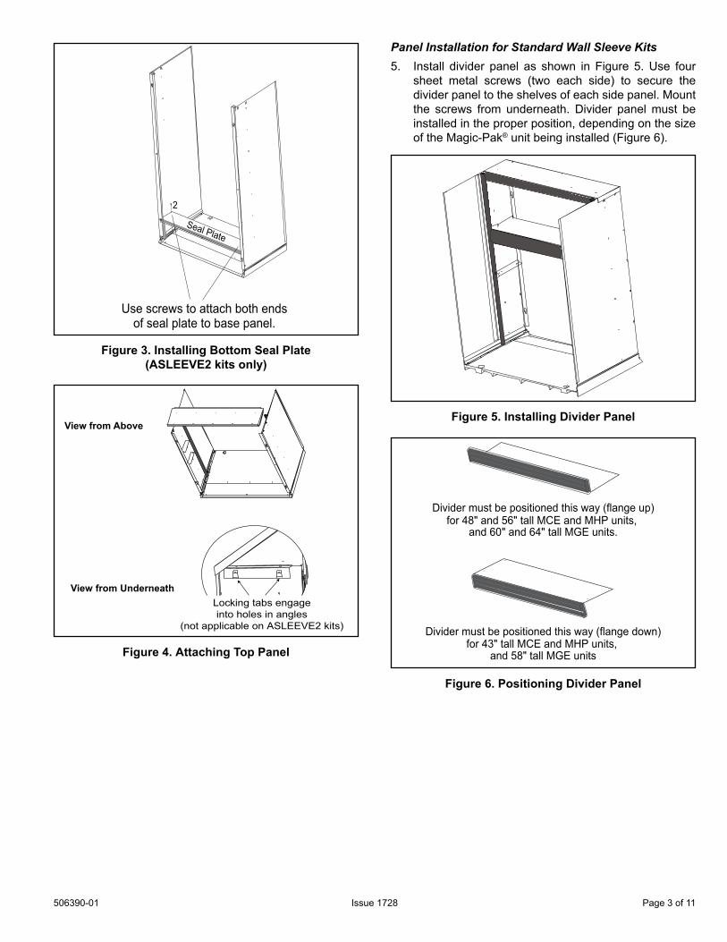
Seal Plate
Use screws to attach both ends of seal plate to base panel.
2
Figure 3. Installing Bottom Seal Plate(ASLEEVE2 kits only)
View from UnderneathLocking tabs engageinto holes in angles
(not applicable on ASLEEVE2 kits)
View from Above
Figure 4. Attaching Top Panel
Panel Installation for Standard Wall Sleeve Kits5. Install divider panel as shown in Figure 5. Use four
sheet metal screws (two each side) to secure the divider panel to the shelves of each side panel. Mount the screws from underneath. Divider panel must be installed in the proper position, depending on the size of the Magic-Pak® unit being installed (Figure 6).
Figure 5. Installing Divider Panel
Divider must be positioned this way (flange up)for 48" and 56" tall MCE and MHP units,
and 60" and 64" tall MGE units.
Divider must be positioned this way (flange down)for 43" tall MCE and MHP units,
and 58" tall MGE units.
Figure 6. Positioning Divider Panel

506390-01Issue 1728Page 4 of 11
Division Height Position
MHP
MHP4-09-12B Down
MHP4-09-18MHP4-09-24
B UpMHP4-09-30MHP4-09-36 A UpMHP4-10-18
B UpMHP4-10-24MHP4-10-30 A Up
MCE
MCE4-09-12B Down
MCE4-09-18MCE4-09-24
B UpMCE4-09-30MCE4-09-36 A UpMCE4-10-18
B UpMCE4-10-24MCE4-10-30 A Up
MGE
MGE4-09-12B Down
MGE4-09-18MGE4-09-24
B UpMGE4-09-30MGE4-09-36 A UpMGE4-10-18
B UpMGE4-10-24MGE4-10-30 A Up
Table 1.
View from UnderneathLocking tabs engageinto holes in angles
(not applicable on ASLEEVE2 kits)
View from Above
Figure 7. Attaching Top Panel
Panel for Universal Wall Sleeve Kits6. Install top panel as shown in Figure 7. Use four sheet
metal screws (two each side) to secure the divider panel to the shelves of each side panel. Divider panel must be installed in the proper position, angle up or
angle down, as well as divider panel placed on the correct shelf height. See Table 1 for panel location and direction. See Figure 8 for shelf location. See Figure 9 for divider panel position. Division panel must be installed before inserted into wall opening.
Division Height
A
B
Figure 8. Installing Divider Panel
Divider Panel Up
Divider Panel Down
Figure 9. Positioning Divider Panel
Flashing Angle Installation (if used)Flashing angles are provided in this wall sleeve kit to allow the installer a means to mount the wall sleeve to the exterior surface of the “rough wall.” Both side panels and the top panel have two sets of .110” diameter holes in them for mounting the flashing angles to each of the panel’s outside surfaces (Figure 10).
Determine which set of holes should be used. Using the row of holes on the side and top panels that are nearest the front of the wall sleeve assembly (the end that will protrude through the wall opening) will extend the wall sleeve 1/2” beyond the outside surface of the “rough wall.” Using the other set of holes will extend the wall sleeve 4-1/2” beyond the outside surface of the “rough wall.”
If your application requires that the wall sleeve be flush with the outside surface of the “rough wall,” reverse the flashing angles and use the holes closest to the front of the wall sleeve.

506390-01 Issue 1728 Page 5 of 11
NOTE: With the flashing angles reversed, the screw heads may interfere with the rough in opening. If this happens, clearance may need to be provided in the opening for the screw heads.
Once the flashing angles are mounted to the wall sleeve, the sleeve can only be inserted from the outside.
It is recommended that caulk be applied between the surfaces of the flashing angles and the wall sleeve panels prior to mounting the flashing angles to the wall sleeve. This will provide a weather seal between the sleeve and the flashing angles.
Using this row of holes will extend the wall sleeve
½" beyond outside wall
Using this row of holes will extend the wall sleeve 4-½" beyond outside wall
Figure 10. Installing Flashing Angles
Wall Sleeve Installation1. If flashing angles have been installed (see previous
section), the wall sleeve can only be inserted through the wall opening from the outside (Figure 11). Push the sleeve all the way into the opening until the flashing angles are up against the outside wall surface.NOTE: Caulk between the flashing angles and the outside wall to provide weather seal.
2. Secure wall sleeve to outside wall with field-supplied deck screws.
3. If flashing angles have not been installed, position wall sleeve base in wall opening as shown in Figure 12.NOTE: The notched edge on each front corner of the base must be positioned correctly.If an aluminum louver will be used in the installation, the notches must line up 1-1/4” back from the face of the outside wall. If a polypropylene louver will be used, the notches must line up 1” from the face of the outside wall.
Figure 11. Installing Wall Sleeve from Outside
Line up this notch in the base the proper distance from the face of the outside wall.
Platform
Wall Sleeve Base
Outside Wall
Caulk and flash betweenwall sleeve base and sill plate of wall opening.
Figure 12. Positioning Wall Sleeve
If the flashing angles were not installed, the wall sleeve will need to be secured to the opening. When the wall sleeve is in the desired position in the wall opening, secure the sleeve using field-supplied screws through the holes provided in the sides and top panels (Figure 13).
Secure sleeve to wallthrough these holes
in top and side panels
Figure 13. Securing Wall Sleeve to Wall Opening(if flashing angles were not installed)
506390-01Issue 1728Page 6 of 11
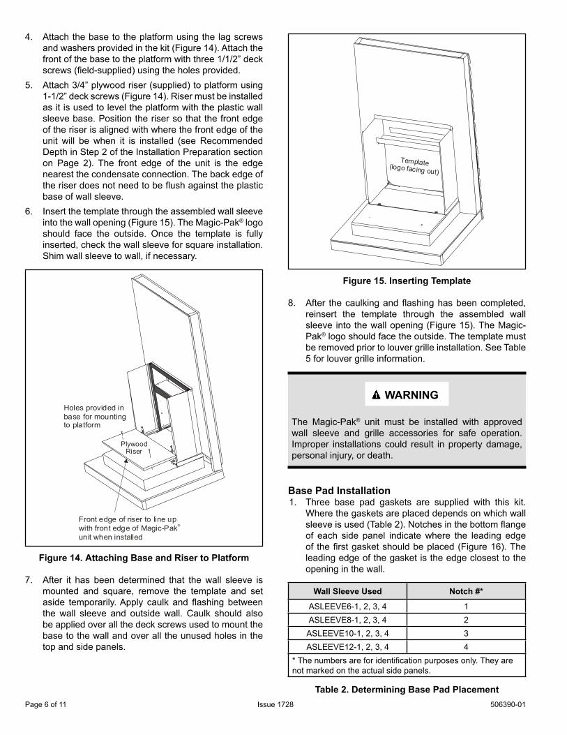
4. Attach the base to the platform using the lag screws and washers provided in the kit (Figure 14). Attach the front of the base to the platform with three 1/1/2” deck screws (field-supplied) using the holes provided.
5. Attach 3/4” plywood riser (supplied) to platform using 1-1/2” deck screws (Figure 14). Riser must be installed as it is used to level the platform with the plastic wall sleeve base. Position the riser so that the front edge of the riser is aligned with where the front edge of the unit will be when it is installed (see Recommended Depth in Step 2 of the Installation Preparation section on Page 2). The front edge of the unit is the edge nearest the condensate connection. The back edge of the riser does not need to be flush against the plastic base of wall sleeve.
6. Insert the template through the assembled wall sleeve into the wall opening (Figure 15). The Magic-Pak® logo should face the outside. Once the template is fully inserted, check the wall sleeve for square installation. Shim wall sleeve to wall, if necessary.
Holes provided in base for mounting to platform
Plywood
Front edge of riser to line up with front edge of Magic-Pak unit when installed
®
Riser
Figure 14. Attaching Base and Riser to Platform
7. After it has been determined that the wall sleeve is mounted and square, remove the template and set aside temporarily. Apply caulk and flashing between the wall sleeve and outside wall. Caulk should also be applied over all the deck screws used to mount the base to the wall and over all the unused holes in the top and side panels.
Template(logo facing out)
Figure 15. Inserting Template
8. After the caulking and flashing has been completed, reinsert the template through the assembled wall sleeve into the wall opening (Figure 15). The Magic-Pak® logo should face the outside. The template must be removed prior to louver grille installation. See Table 5 for louver grille information.
WARNING
The Magic-Pak® unit must be installed with approved wall sleeve and grille accessories for safe operation. Improper installations could result in property damage, personal injury, or death.
Base Pad Installation1. Three base pad gaskets are supplied with this kit.
Where the gaskets are placed depends on which wall sleeve is used (Table 2). Notches in the bottom flange of each side panel indicate where the leading edge of the first gasket should be placed (Figure 16). The leading edge of the gasket is the edge closest to the opening in the wall.
Wall Sleeve Used Notch #*
ASLEEVE6-1, 2, 3, 4 1ASLEEVE8-1, 2, 3, 4 2
ASLEEVE10-1, 2, 3, 4 3ASLEEVE12-1, 2, 3, 4 4
* The numbers are for identification purposes only. They are not marked on the actual side panels.
Table 2. Determining Base Pad Placement

506390-01 Issue 1728 Page 7 of 11
1
423
Notches** The numbers are for identification purposes only. They are not marked on the actual side panels.
Figure 16. Identifying Side Panel Notches
NOTE: Before attaching the base pads to the plastic base panel or plywood riser, make sure the surfaces are completely cleaned of oil or debris.Remove the paper backing of the base pad and align the leading edge of the first gasket to the proper notches found in the left and right side panels. Press gasket firmly in place making sure that adhesive on entire gasket comes in contact with the wall sleeve base.
2. Place the second base pad on the plywood riser. The front edge of the pad should align with the front edge of the plywood riser (Figure 17). If the riser has been installed correctly (see Step 5 on Page 6), the front edge of the plywood riser (and base pad) will be aligned with the front edge of the unit when it is installed. Press pad firmly into place.
3. The third base pad can be placed anywhere between the first and second gaskets as long as it is entirely positioned on either the plastic base panel or the plywood riser. This pad must not be placed partially on both surfaces.
4. Caulk along the edges of the first base pad where it meets the left and right side panels. Caulk should also be applied in the corners where the base pads and the side panels gaskets meet (Figure 17).
Install this base pad first
Install this base pad second
Install this base pad lastCaulk where base pad and side panels meet and in corners where side panel
gaskets and base pads meet
Figure 17. Installing Base Pads

506390-01Issue 1728Page 8 of 11
Letter Quantity Description
A 1 Top Panel AssemblyB 1 BaseC 1 Left Side Panel AssemblyD 1 Right Side Panel AssemblyE 1 3/4” Plywood RiserF 2 Divider Panel AssemblyG 1 Template-- 2 Lag Screws and Washers-- 12 Sheet Metal Screws-- 1 Installation Instructions
B
C
D
A
E
F
G
Parts

506390-01 Issue 1728 Page 9 of 11
Accessories
Kit No. Description Used With
ASLEEVE2-1* 2” Wall Sleeve KitMCE/MGE/MHP9-10, 18, 24 & 30
MCE/MGE/MHP12, 18, & 24
ASLEEVE2-2* 2” Wall Sleeve KitMCE/MGE/MHP9-36
MCE/MGE/MHP10 - 30
ASLEEVE-3* Wall Sleeve Kit (45” Louver) MCE/MHP9 SEER -1 AND 1.5 TON UNITS
ASLEEVE6-01 6” Wall Sleeve KitMCE/MGE/MHP9 SEER - ALL UNITS
MCE/MGE/MHP10 SEER - 1.5 & 2 TON UNITS
ASLEEVE6-2** 6” Wall Sleeve Kit MCE/MGE/MHP10 SEER - 2.5 TON UNITS
ASLEEVE8-1 8” Wall Sleeve KitMCE/MGE/MHP 9 SEER - ALL UNITS
MCE/MGE/MHP 10 SEER - 1.5 & 2 TON UNITS
ASLEEVE8-2** 8” Wall Sleeve Kit MCE/MGE/MHP 10 SEER - 2.5 TON UNITS
ASLEEVE10-1 10” Wall Sleeve KitMCE/MGE/MHP 9 SEER - ALL UNITS
MCE/MGE/MHP 10 SEER - 1.5 AND 2 TON UNITS
ASLEEVE10-2** 10” Wall Sleeve Kit MCE/MGE/MHP 10 SEER - 2.5 TON UNITS
ASLEEVE12-1 12” Wall Sleeve KitMCE/MGE/MHP 9 SEER - ALL UNITS
MCE/MGE/MHP 10 SEER - 1.5 & 2 TON UNITS
ASLEEVE12-2** 12” Wall Sleeve Kit MCE/MGE/MHP 10 SEER - 2.5 TON UNITS
ASLEEVE6-3 6” Wall Sleeve for 45” LouverMCE/MGE/MHP 9 SEER - 2 & 2.5 TON UNITS
MCE/MGE/MHP 10 SEER - 1.5 & 2 TON UNITS
ASLEEVE6-4 6” Wall Sleeve for 45” Louver MCE/MGE/MHP 10 SEER - 2.5 TON UNITS
ASLEEVE8-3 8” Wall Sleeve for 45” LouverMCE/MGE/MHP 9 SEER - 2 & 2.5 TON UNITS
MCE/MGE/MHP 10 SEER - 1.5 & 2 TON UNITS
ASLEEVE8-4 8” Wall Sleeve for 45” Louver MCE/MGE/MHP 10 SEER - 2.5 TON UNITS
ASLEEVE10-3 10” Wall Sleeve for 45” LouverMCE/MGE/MHP 9 SEER - 2 & 2.5 TON UNITS
MCE/MGE/MHP 10 SEER - 1.5 & 2 TON UNITS
ASLEEVE10-4 10” Wall Sleeve for 45” Louver MCE/MGE/MHP 10 SEER - 2.5 TON UNITS
ASLEEVE12-3 12” Wall Sleeve for 45” LouverMCE/MGE/MHP 9 SEER - 2 & 2.5 TON UNITS
MCE/MGE/MHP 10 SEER - 1.5 & 2 TON UNITS
ASLEEVE12-4 12” Wall Sleeve for 45” Louver MCE/MGE/MHP 10 SEER - 2.5 TON UNITS
* Thru-the-wall installations only** Universal Sleeve Kit Wall
Table 3. Wall Sleeve Kits

506390-01Issue 1728Page 10 of 11
Kit No. A B C D
ASLEEVE2-1* 2 29 29-1/8 29-1/8
ASLEEVE2-2* 2 32-3/4 32-7/8 29-1/8
ASLEEVE6-01 6 29 29-1/8 29-1/8
ASLEEVE6-2** 6 32-3/4 32-7/8 29-1/8
ASLEEVE6-36 45 45-1/8 29-1/8
ASLEEVE6-4
ASLEEVE8-1 8 29 29-1/8 29-1/8
ASLEEVE8-2** 8 32-3/4 32-7/8 29-1/8
ASLEEVE8-38 45 45-1/8 29-1/8
ASLEEVE8-4
ASLEEVE10-1 10 29 29-1/8 29-1/8
ASLEEVE10-2** 10 32-3/4 32-7/8 29-1/8
ASLEEVE10-310 45 45-1/8 29-1/8
ASLEEVE10-4
ASLEEVE12-1 12 29 29-1/8 29-1/8
ASLEEVE12-2** 12 32-3/4 32-7/8 29-1/8
ASLEEVE12-312 45 45-1/8 29-1/8
ASLEEVE12-4
ASLEEVE-3* * 45 45-1/8 29-1/8
Table 4. Wall Sleeve Dimensions (in.)
B
A
C
D
Required Wall Opening
Range ofWall Thickness
16-5/829
161-1/2
NOTE: Bottom surface of wall opening must be at least 4” off the floor.

506390-01 Issue 1728 Page 11 of 11
Kit Number Description Used With
ALVRPWHT-1 Polypropylene Louver Kit (White) MCE/MHP9-10,18,24 & 30 MCE/MHP10-18 & 24
ALVRPWHT-2 Polypropylene Louver Kit (White) MCE/MHP9-36 & MCE/MHP10-30
ALVRPSAN-1 Polypropylene Louver Kit (Sandstone) MCE/MHP9-10,18,24 & 30 MCE/MHP10,18 & 24
ALVRPSAN-2 Polypropylene Louver Kit (Sandstone) MCE/MHP9,36 & MCE/MHP10,30
ALVRPBGE-1 Polypropylene Louver Kit (Beige) MCE/MHP9-10,18,24 & 30 MCE/MHP10,18 & 24
ALVRPBGE-2 Polypropylene Louver Kit (Beige) MCE/MHP9,36 & MCE/MHP10,30
ALVRPTPST-1 Polypropylene Louver Kit (Taupestone) MCE/MHP9-12,18,24 & 30 MCE/MHP10,18 & 24
ALVRPTPST-2 Polypropylene Louver Kit (Taupestone) MCE/MHP9,36 & MCD/MHP10,30
ALVRPWHTMGE-1 Polypropylene Louver Kit (White) MGE9-12,18,24 & 30 MGE10,18 & 24
ALVRPWHTMGE-2 Polypropylene Louver Kit (White) MGE9,36/MGE10,30
ALVRPSANMGE-1 Polypropylene Louver Kit (Sandstone) MGE9-12,18,24 & 30 MGE10,18 & 24
ALVRPSANMGE-2 Polypropylene Louver Kit (Sandstone) MGE9,36/MGE10,30
ALVRPBGEMGE-1 Polypropylene Louver Kit (Beige) MGE9-12,18,24 & 30 MGE10,18 & 24
ALVRPBGEMGE-2 Polypropylene Louver Kit (Beige) MGE9,36/MGE10,30
ALVRPTPSTMGE-1 Polypropylene Louver Kit (Taupestone) MGE9-12,18,24 & 30 MGE10,18 & 24
ALVRPTPSTMGE-2 Polypropylene Louver Kit (Taupestone) MGE9,36/MGE10,30
ALVRAL-1 Extruded Aluminum Louver Kit MCE/MGE/MHP9-12,18,24 & 30 MCE/MGE/MHP10,18 & 24
ALVRAL-2 Extruded Aluminum Louver Kit MCE/MGE/MHP9,36 & MCE/MGE/MHP10,30
ALVRAL-3 Extruded Aluminum Louver Kit (45” Height) MCE/MGE/MHP9-10,18,24 & 30 MCE/MGE/MHP10,18 & 24
ALVRAL-4 Extruded Aluminum Louver Kit (45” Height) MCE/MGE/MHP9,36 & MCE/MGE/MHP10,30
ALVRAL-5 Extruded Aluminum Louver Kit (50” Height) MCE/MGE/MHP9-12,18,24 & 30 MCE/MGE/MHP10,18 & 24
ALVRAL-6 Extruded Aluminum Louver Kit (50” Height) MCE/MGE/MHP9,36 & MCE/MGE/MHP10,30
Table 5. Louver Kits