Embed Size (px)
Citation preview

LS-50B User’s Guide
Release History
Part Number Release Publication Date
0993 4317 A October 1999
User Assistance Perkin Elmer Ltd Post Office Lane Beaconsfield Buckinghamshire HP9 1QA Printed in the United Kingdom. Notices The information contained in this document is subject to change without notice. Perkin Elmer makes no warranty of any kind with regard to the material, including, but not limited to, the implied warranties of merchantability and fitness for a particular purpose. Perkin Elmer shall not be liable for errors contained herein for incidental consequential damages in connection with furnishing, performance or use of this material. Copyright Information This document contains proprietary information that is protected by copyright. All rights are reserved. No part of this publication may be reproduced in any form whatsoever or translated into any language without the prior, written permission of Perkin Elmer LLC or its affiliates. Copyright © 1999 Perkin Elmer LLC Trademarks Registered names, trademarks, etc. used in this document, even when not specifically marked as such, are protected by law. Perkin Elmer is a registered trademark of affiliates of Perkin Elmer LLC. FL WinLab is a trademark of the Perkin Elmer LLC. Windows is a trademark of the Microsoft Corporation.

LS-50B User’s Guide
3
Contents Contents ..........................................................................................................3 Warnings and Safety Information...............................................................7 Safety Information ..........................................................................................9
Environmental conditions for safe operation...........................................9 Warning Labels on the Instrument................................................................11
Further assistance...................................................................................12 Introduction.................................................................................................13 About this Manual.........................................................................................15
Conventions ...........................................................................................15 Definitions .............................................................................................18
Specifications of the LS-50B ........................................................................19 Unpacking and Installation ........................................................................21 Introduction...................................................................................................23 Shipping kit list (L225-0001)........................................................................25 Lifting the LS-50B Luminescence Spectrometer..........................................26 Removal of the shipping clamps ...................................................................27 Electrical Connections ..................................................................................30
Connection to electrical mains supply ...................................................30 Accessory connectors ............................................................................30 Rear panel connectors............................................................................31
Switching on the LS-50B..............................................................................35 Accessories: Installation and Use...............................................................37 Single Position Cellholder (standard) ...........................................................39
Description.............................................................................................39 Installation and maintenance..................................................................39
Stirred Single Position Cellholder.................................................................40 Description.............................................................................................40 Installation and maintenance..................................................................40 Operation ...............................................................................................40
Stirred Four-Position Cellchanger.................................................................41 Description.............................................................................................41 Installation and maintenance..................................................................41
Biokinetics Accessory...................................................................................42 Description.............................................................................................42 Installation and maintenance..................................................................42 Operation ...............................................................................................43
Screw-fitting Flowcell...................................................................................44 Description.............................................................................................44

LS-50B User’s Guide
4
Installation and maintenance..................................................................45 Operation ...............................................................................................45
Installing Thermostatting Tubing to Cellholders ..........................................46 The four-position cellchanger ................................................................48
Using the Septum Injector.............................................................................49 Using Stirrer Bars..........................................................................................51 Minimum volumes with various cuvette types .............................................52 Semi-micro Cuvette and Holder....................................................................53
Description.............................................................................................53 Installation .............................................................................................53
Stirred Semi-micro Cuvette ..........................................................................54 Description.............................................................................................54 Operation ...............................................................................................55
Care of Optical Mirrors Inside Cellholder Accessories ................................56 Resistance to Solvents...................................................................................57 Sipper ............................................................................................................58
Description.............................................................................................58 Installation and maintenance..................................................................59 Operation ...............................................................................................61
LC Flowcell ..................................................................................................64 Description.............................................................................................64 Installation .............................................................................................64 Operation ...............................................................................................66
Front Surface Accessory ...............................................................................67 Description.............................................................................................67 Installation and maintenance..................................................................68 Operation ...............................................................................................71 Using Powders .......................................................................................72
The Perfusion Coverslip Accessory..............................................................74 Description.............................................................................................74 Installation .............................................................................................77
Plate Reader ..................................................................................................78 Description.............................................................................................78 Installation .............................................................................................78 Operation ...............................................................................................85 The Well Plate Reader application ........................................................85 The TLC Scan application .....................................................................86 Measuring TLC plates, gels or other flat samples .................................87
Red-sensitive Detector ..................................................................................88 Description.............................................................................................88 Installation .............................................................................................89
Total Emission Accessory.............................................................................90

LS-50B User’s Guide
5
Description.............................................................................................90 Installation .............................................................................................90 Operation ...............................................................................................91
External Fibre Optic Accessory ....................................................................92 Description.............................................................................................92 Installation .............................................................................................93 Operation ...............................................................................................97
The Fast Filter Accessory .............................................................................99 Description.............................................................................................99 Installation ...........................................................................................101 Operation .............................................................................................109
The Polarizer Accessory .............................................................................110 Description...........................................................................................110 Installation ...........................................................................................111 Operation .............................................................................................115
Accessory spares .........................................................................................116 RS232 Commands.....................................................................................117 Introduction.................................................................................................119
VME Instrument Control Board Bit Switch Settings...........................121 Section 1- RS232C Communications..........................................................122
Monochromator Drive .........................................................................124 Plate Reader Driver..............................................................................124 Source Control and Photomultiplier Control .......................................125 Slit and Filter Motors...........................................................................125 Analogue Output..................................................................................126 Sample Acquisition Accessories..........................................................126 Fast Filter Accessory (FFA) ................................................................127
Section 2 - Command Formats....................................................................128 Monochromator Scan Control Commands ..........................................130 Time Drive Commands........................................................................133 TLC Scan Commands..........................................................................136 Data Collection/Processing Set Up Commands...................................140 Data Output Control Commands .........................................................145 Motor Control ......................................................................................146 Calibration Commands ........................................................................149 Miscellaneous Commands ...................................................................150 Plug-in Accessory Control Commands................................................154 Fast Kinetics Application (FKA) Commands......................................156 Fast Filter Accessory (FFA) Commands .............................................159
System Description and Maintenance .....................................................161 The Optical System.....................................................................................163 The Electronics System and Signal Handling.............................................165

LS-50B User’s Guide
6
Instrument Modes ................................................................................166 Signal Handling Diagram ....................................................................169
Fuses ...........................................................................................................170 Other Fuses ..........................................................................................171
Removing the Main Cover..........................................................................172 Refitting the main cover ......................................................................174
Removing the Main Optical Cover .............................................................175 Refitting the optical cover....................................................................177
Customizing filter wheels ...........................................................................178 Changing the Lamp.....................................................................................180 Changing the photomultiplier .....................................................................187 Preparing the LS-50B for transport.............................................................194
Inserting the clamps .............................................................................194 Lifting the LS-50B Luminescence Spectrometer.................................197 Removing the clamps...........................................................................197
Cleaning the air filter ..................................................................................198 Changing the Instrument Operating Voltage ..............................................199
Changing the mains fuse......................................................................201 The mains voltage plate .......................................................................202
Index...........................................................................................................203 Index ...........................................................................................................205

Warnings and Safety Information 1


Warnings and Safety Information
9
Safety Information
The LS-50B Luminescence Spectrometer has been designed and tested in accordance with Perkin Elmer Specifications and IEC 61010-1, 'Safety requirements for electrical equipment for measurement, control and laboratory use'.
This apparatus is protected in accordance with IEC Class 1 rating. This manual contains information and warnings that must be followed by the operator to ensure safe operation and to retain the instrument in a safe condition.
The instrument has been designed for indoor use and will operate correctly under the following conditions:
Ambient temperature 15 °C to 35 °C
Relative humidity 75% maximum, non-condensing
Environmental conditions for safe operation
The LS-50B has been designed to be safe under the following conditions:
• Indoor use.
• Altitude up to 2000 m.
• Temperature range 5 °C to 40 °C.
• Maximum relative humidity 80% for temperatures up to 31 °C, decreasing linearly to 50% relative humidity at 40 °C.
• Mains voltage fluctuations not to exceed 10% of the nominal voltage.
• An IEC Installation Category II (Overvoltage Category II) classification, suitable for connection to local level power supplies.
• An IEC Pollution Degree 2 classification: normally only non-conductive pollution occurs, occasionally, however, a temporary conductivity caused by condensation must be expected.
LS-50B User’s Guide
10
WARNING
This equipment must be earthed (grounded).
Any interruption of the protective conductor, inside or outside the instrument, or disconnection of the protective earth terminal is likely to make the instrument dangerous.
When the instrument is connected to the mains supply, terminals may be hazardous when live and the opening of covers or the removal of parts (except those to which access can be gained by hand) is likely to expose live parts. Any adjustment, maintenance and repair of the opened operating instrument must be carried out only by a skilled person who is aware of the hazards involved (a RESPONSIBLE BODY). The instrument must be disconnected from all voltage sources before it is opened for any adjustment, replacement, maintenance or repair.
Capacitors inside the instrument may still be charged even if the instrument has been disconnected from all voltage sources. Only fuses with the required current and voltage rating and of the specified type are to be used for replacement. Makeshift fuses must NOT be used and fuse holders must not be short-circuited.
Whenever it is likely that the protection has been impaired, the instrument must be made inoperative and secured against any unauthorized operation. The protection is likely to be impaired, for example, when the instrument:
• shows visible damage;
• fails to perform the intended measurement;
• has been subjected to prolonged storage under unfavorable conditions;
• has been subjected to severe transport stresses.
Warnings and Safety Information
11
Warning Labels on the Instrument
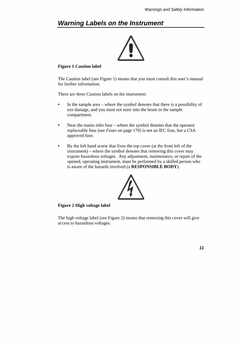
Figure 1 Caution label
The Caution label (see Figure 1) means that you must consult this user’s manual for further information.
There are three Caution labels on the instrument:
• In the sample area – where the symbol denotes that there is a possibility of eye damage, and you must not stare into the beam in the sample compartment.
• Near the mains inlet fuse – where the symbol denotes that the operator replaceable fuse (see Fuses on page 170) is not an IEC fuse, but a CSA approved fuse.
• By the left hand screw that fixes the top cover (at the front left of the instrument) – where the symbol denotes that removing this cover may expose hazardous voltages. Any adjustment, maintenance, or repair of the opened, operating instrument, must be performed by a skilled person who is aware of the hazards involved (a RESPONSIBLE BODY).
Figure 2 High voltage label
The high voltage label (see Figure 2) means that removing this cover will give access to hazardous voltages.

LS-50B User’s Guide
12
There are two High Voltage labels on the instrument:
• Inside the instrument on top of the source cover.
• Inside the instrument on top of the monochromator cover (on the right side of the instrument).
Both these labels mean that the instrument must be switched off, and the mains supply lead removed from its socket before the cover is removed. Any adjustment, maintenance, or repair of the opened, operating instrument, must be performed by a skilled person who is aware of the hazards involved (a RESPONSIBLE BODY).
Further assistance
For technical assistance, please contact your local Perkin Elmer office or agent, or the address at the front of this manual.

Introduction 2


Introduction
15
About this Manual
This LS-50B User's Guide describes specifications and the installation of the LS-50B Luminescence spectrometer and its accessories.
Information about the FL WinLab Software package can be found in the FL WinLab User's Guide, which is delivered with the instrument.
Conventions
The following conventions are used in this manual:
• Normal text is used to provide information and instructions.
• Bold text refers to text that is displayed on the screen.
• UPPERCASE text, for example ENTER or ALT, refers to keys on the PC keyboard. '+' is used to show that you have to press two keys at the same time, for example, ALT+F.
• All eight character ‘numbers’, for example L225-0140, are Perkin Elmer part numbers unless stated otherwise.
Notes, warnings and cautions
Three terms, in the following standard formats, are also used to highlight special circumstances and warnings.
NOTE: A note indicates additional, significant information that is provided with some procedures.
LS-50B User’s Guide
16
WARNING
We use the term WARNING to inform you about situations that could result in personal injury to yourself or other persons. Details about these circumstances are in a box like this one.
D Warning (Warnung) Bedeutet, daß es bei Nichtbeachten der genannten Anweisung zu einer Verletzung des Benutzers kommen kann.
DK Warning (Advarsel) Betyder, at brugeren kan blive kvæstet, hvis anvisningen ikke overholdes.
E Warning (Peligro) Utilizamos el término WARNING (PELIGRO) para informarle sobre situaciones que pueden provocar daños personales a usted o a otras personas. En los recuadros como éste se proporciona información sobre este tipo de circunstancias.
F Warning (Danger) Nous utilisons la formule WARNING (DANGER) pour avertir des situations pouvant occasionner des dommages corporels à l'utilisateur ou à d'autres personnes. Les détails sur ces circonstances sont données dans un encadré semblable à celui-ci.
I Warning (Pericolo) Con il termine WARNING (PERICOLO) vengono segnalate situazioni che potrebbero provocare incidenti alle persone. Troverete informazioni su tali circostanze in un riquadro come questo.
NL Warning (Waarschuwing) Betekent dat, wanneer de genoemde aanwijzing niet in acht wordt genomen, dit kan leiden tot verwondingen van de gebruiker.
P Warning (Aviso) Significa que a não observância da instrução referida poderá causar um ferimento ao usuário.
Introduction
17
CAUTION
We use the term CAUTION to inform you about situations that could result in serious damage to the instrument or other equipment. Details about these circumstances are in a box like this one.
D Caution (Achtung) Bedeutet, daß die genannte Anleitung genau befolgt werden muß, um einen Geräteschaden zu vermeiden.
DK Caution (Bemærk) Dette betyder, at den nævnte vejledning skal overholdes nøje for at undgå en beskadigelse af apparatet.
E Caution (Advertencia) Utilizamos el término CAUTION (ADVERTENCIA) para advertir sobre situaciones que pueden provocar averías graves en este equipo o en otros. En recuadros éste se proporciona información sobre este tipo de circunstancias.
F Caution (Attention) Nous utilisons le terme CAUTION (ATTENTION) pour signaler les situations susceptibles de provoquer de graves détériorations de l'instrument ou d'autre matériel. Les détails sur ces circonstances figurent dans un encadré semblable à celui-ci.
I Caution (Attenzione) Con il termine CAUTION (ATTENZIONE) vengono segnalate situazioni che potrebbero arrecare gravi danni allo strumento o ad altra apparecchiatura. Troverete informazioni su tali circostanze in un riquadro come questo.
NL Caution (Opgelet) Betekent dat de genoemde handleiding nauwkeurig moet worden opgevolgd, om beschadiging van het instrument te voorkomen.
P Caution (Atenção) Significa que a instrução referida tem de ser respeitada para evitar a danificação do aparelho.

LS-50B User’s Guide
18
Definitions
OPERATOR: Person operating the equipment for its intended purpose.
RESPONSIBLE BODY: Individual or group responsible for the use and maintenance of the equipment and for ensuring that the OPERATORS are adequately trained.
Introduction
19
Specifications of the LS-50B
Principle: Computer controlled ratioing luminescence spectrometer with the capability of measuring fluorescence, phosphorescence, chemiluminescence and bioluminescence
Source: Xenon discharge lamp, equivalent to 20 kW for 8 µs duration. Pulse width at half height <10 µs.
Sample detector: Gated photomultiplier with modified S5 response for operation up to around 650 nm. Red-sensitive R928 photomultiplier can be optionally fitted for operation up to 900 nm.
Reference detector: Gated photomultiplier with modified S5 response for operation up to around 650 nm.
Monochromators: Monk-Gillieson type monochromators cover the following ranges:
• Excitation 200-800 nm with zero order selectable.
• Emission 200-650 nm with standard photomultiplier with zero order selectable, 200-900 nm with optional R928 photomultiplier.
Synchronous scanning is available with constant wavelength or constant energy difference.
Wavelength accuracy: +1.0 nm
Wavelength reproducibility: +0.5 nm
Spectral bandpass: The excitation slits (2.5-15.0 nm) and emission slits (2.5-20.0 nm) can be varied and selected in 0.1 nm increments.
Phosphorescence mode: Delay and gate times can be varied to measure phosphorescence. Minimum total period 13.0 ms (50 Hz)
Scanning speed: Scanning speed can be selected in increments of 1 nm for 10-1500 nm/min. Time-dependent data can also be collected.

LS-50B User’s Guide
20
Emission filters: Computer selectable cut-off (high-pass) filters at 290, 350, 390, 430 and 515 nm, a blank (to act as shutter), a 1% T attenuator and clear beam position.
Sensitivity: Signal to noise is 500:1 r.m.s., using the Raman band of water with excitation at 350 nm, excitation and emission bandpass 10 nm.
Standard cellholder: A single position water thermostattable holder for 10 mm cuvettes.

Unpacking and Installation 3

Unpacking and Installation
23
Introduction
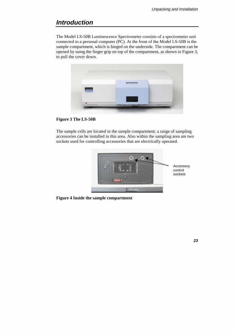
The Model LS-50B Luminescence Spectrometer consists of a spectrometer unit connected to a personal computer (PC). At the front of the Model LS-50B is the sample compartment, which is hinged on the underside. The compartment can be opened by using the finger grip on top of the compartment, as shown in Figure 3, to pull the cover down.
Figure 3 The LS-50B
The sample cells are located in the sample compartment; a range of sampling accessories can be installed in this area. Also within the sampling area are two sockets used for controlling accessories that are electrically operated.
Figure 4 Inside the sample compartment
Accessory control sockets
LS-50B User’s Guide
24
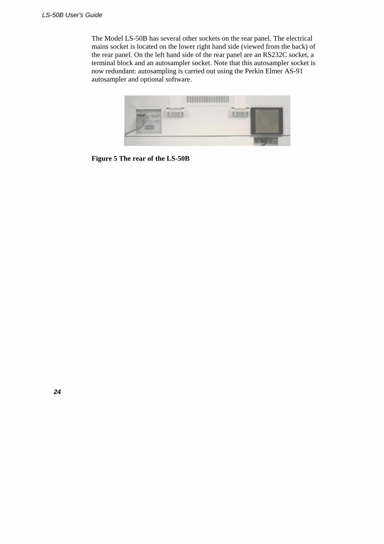
The Model LS-50B has several other sockets on the rear panel. The electrical mains socket is located on the lower right hand side (viewed from the back) of the rear panel. On the left hand side of the rear panel are an RS232C socket, a terminal block and an autosampler socket. Note that this autosampler socket is now redundant: autosampling is carried out using the Perkin Elmer AS-91 autosampler and optional software.
Figure 5 The rear of the LS-50B
Unpacking and Installation
25
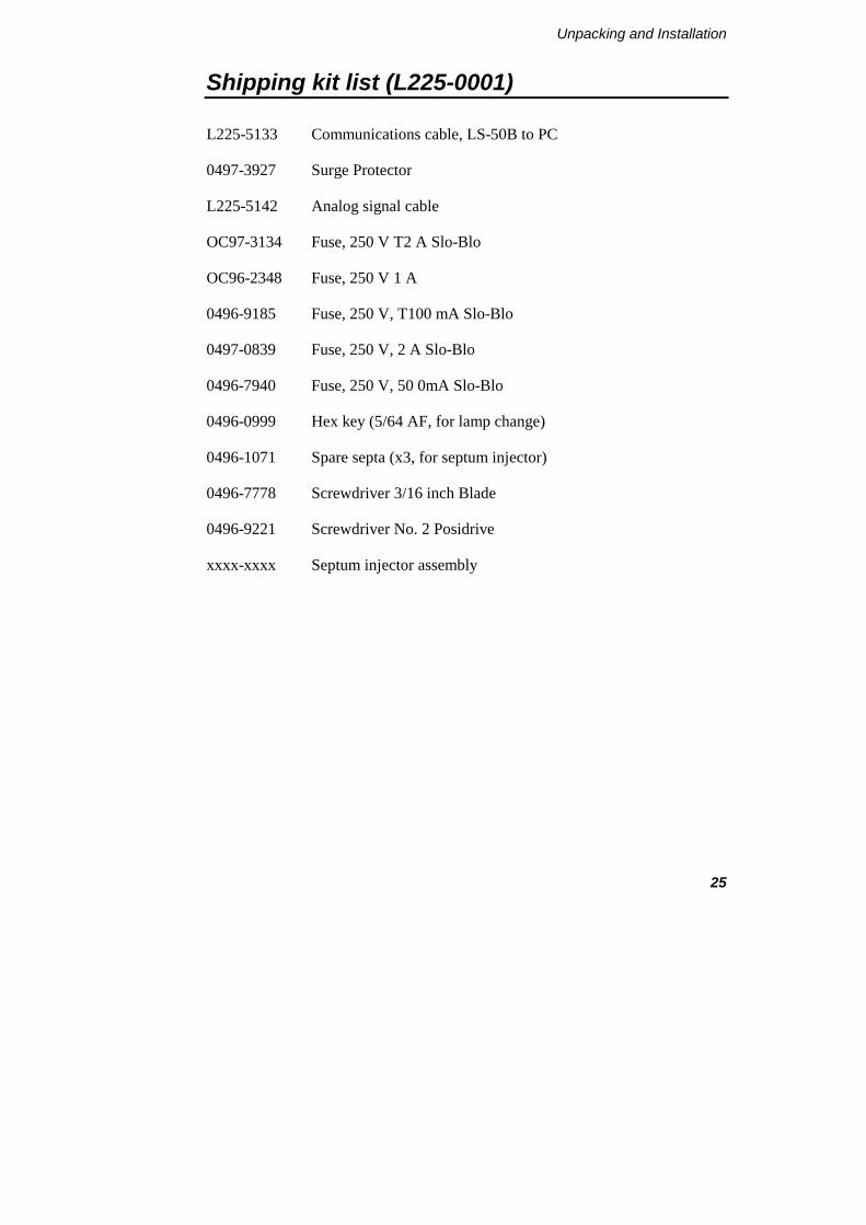
Shipping kit list (L225-0001)
L225-5133 Communications cable, LS-50B to PC
0497-3927 Surge Protector
L225-5142 Analog signal cable
OC97-3134 Fuse, 250 V T2 A Slo-Blo
OC96-2348 Fuse, 250 V 1 A
0496-9185 Fuse, 250 V, T100 mA Slo-Blo
0497-0839 Fuse, 250 V, 2 A Slo-Blo
0496-7940 Fuse, 250 V, 50 0mA Slo-Blo
0496-0999 Hex key (5/64 AF, for lamp change)
0496-1071 Spare septa (x3, for septum injector)
0496-7778 Screwdriver 3/16 inch Blade
0496-9221 Screwdriver No. 2 Posidrive
xxxx-xxxx Septum injector assembly

LS-50B User’s Guide
26
Lifting the LS-50B Luminescence Spectrometer
WARNING
Consult local codes of practice issued by safety advisors before attempting to lift the spectrometer.
As the LS-50B Luminescence Spectrometer weighs approximately 49 Kg (approximately 59 Kg with packaging), we recommend that the spectrometer is lifted by 2 adults, and that it is lifted by the base of the instrument.
Unpacking and Installation
27
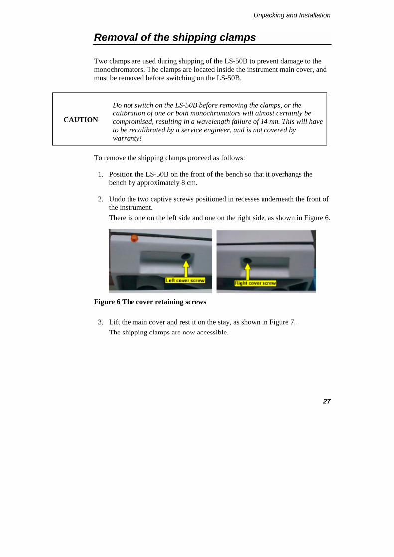
Removal of the shipping clamps
Two clamps are used during shipping of the LS-50B to prevent damage to the monochromators. The clamps are located inside the instrument main cover, and must be removed before switching on the LS-50B.
CAUTION
Do not switch on the LS-50B before removing the clamps, or the calibration of one or both monochromators will almost certainly be compromised, resulting in a wavelength failure of 14 nm. This will have to be recalibrated by a service engineer, and is not covered by warranty!
To remove the shipping clamps proceed as follows:
1. Position the LS-50B on the front of the bench so that it overhangs the bench by approximately 8 cm.
2. Undo the two captive screws positioned in recesses underneath the front of the instrument. There is one on the left side and one on the right side, as shown in Figure 6.
Figure 6 The cover retaining screws
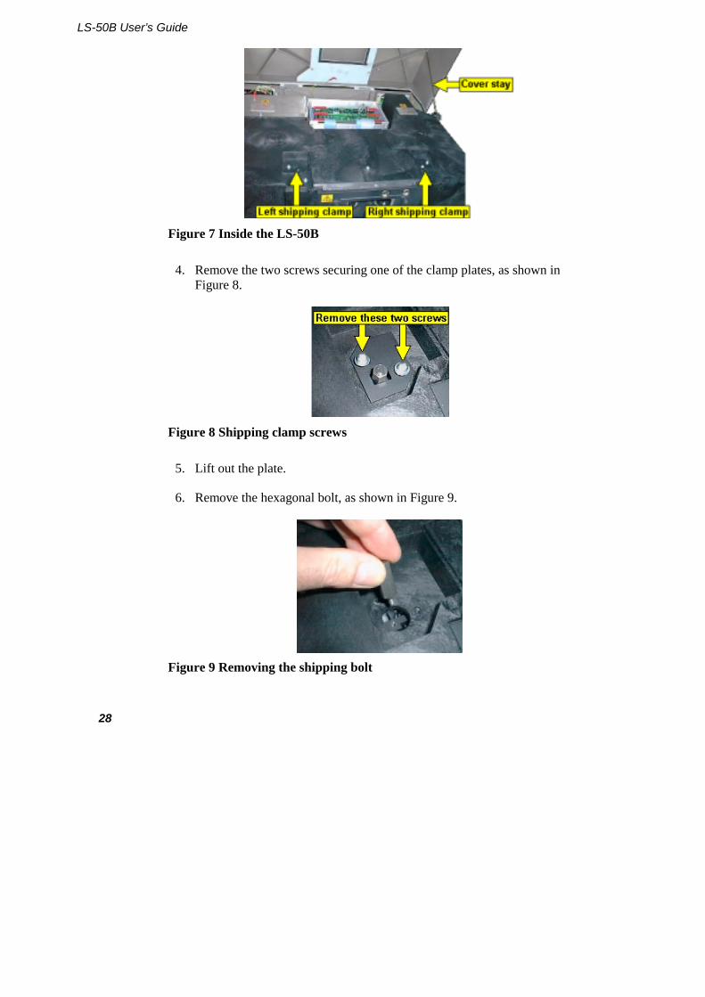
3. Lift the main cover and rest it on the stay, as shown in Figure 7. The shipping clamps are now accessible.
LS-50B User’s Guide
28
Figure 7 Inside the LS-50B
4. Remove the two screws securing one of the clamp plates, as shown in Figure 8.
Figure 8 Shipping clamp screws
5. Lift out the plate.
6. Remove the hexagonal bolt, as shown in Figure 9.
Figure 9 Removing the shipping bolt
Unpacking and Installation
29
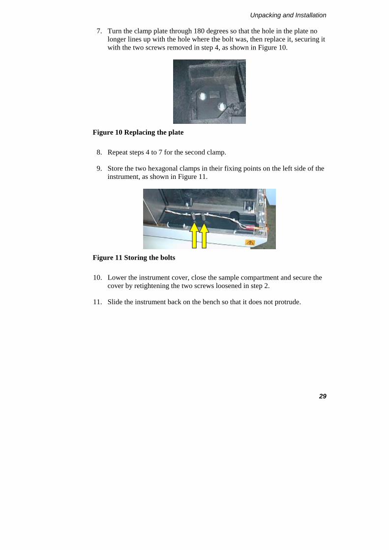
7. Turn the clamp plate through 180 degrees so that the hole in the plate no longer lines up with the hole where the bolt was, then replace it, securing it with the two screws removed in step 4, as shown in Figure 10.
Figure 10 Replacing the plate
8. Repeat steps 4 to 7 for the second clamp.
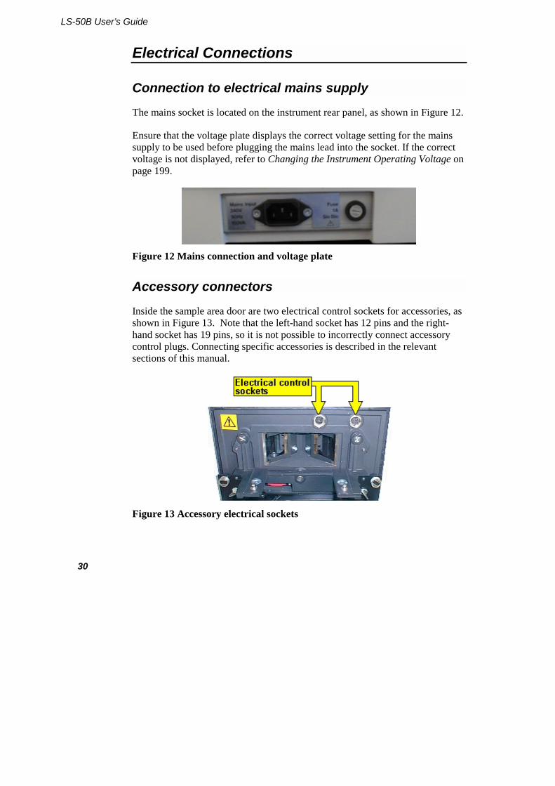
9. Store the two hexagonal clamps in their fixing points on the left side of the instrument, as shown in Figure 11.
Figure 11 Storing the bolts
10. Lower the instrument cover, close the sample compartment and secure the cover by retightening the two screws loosened in step 2.
11. Slide the instrument back on the bench so that it does not protrude.
LS-50B User’s Guide
30
Electrical Connections
Connection to electrical mains supply
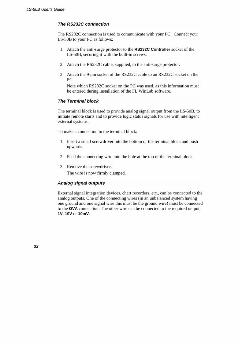
The mains socket is located on the instrument rear panel, as shown in Figure 12.
Ensure that the voltage plate displays the correct voltage setting for the mains supply to be used before plugging the mains lead into the socket. If the correct voltage is not displayed, refer to Changing the Instrument Operating Voltage on page 199.
Figure 12 Mains connection and voltage plate
Accessory connectors
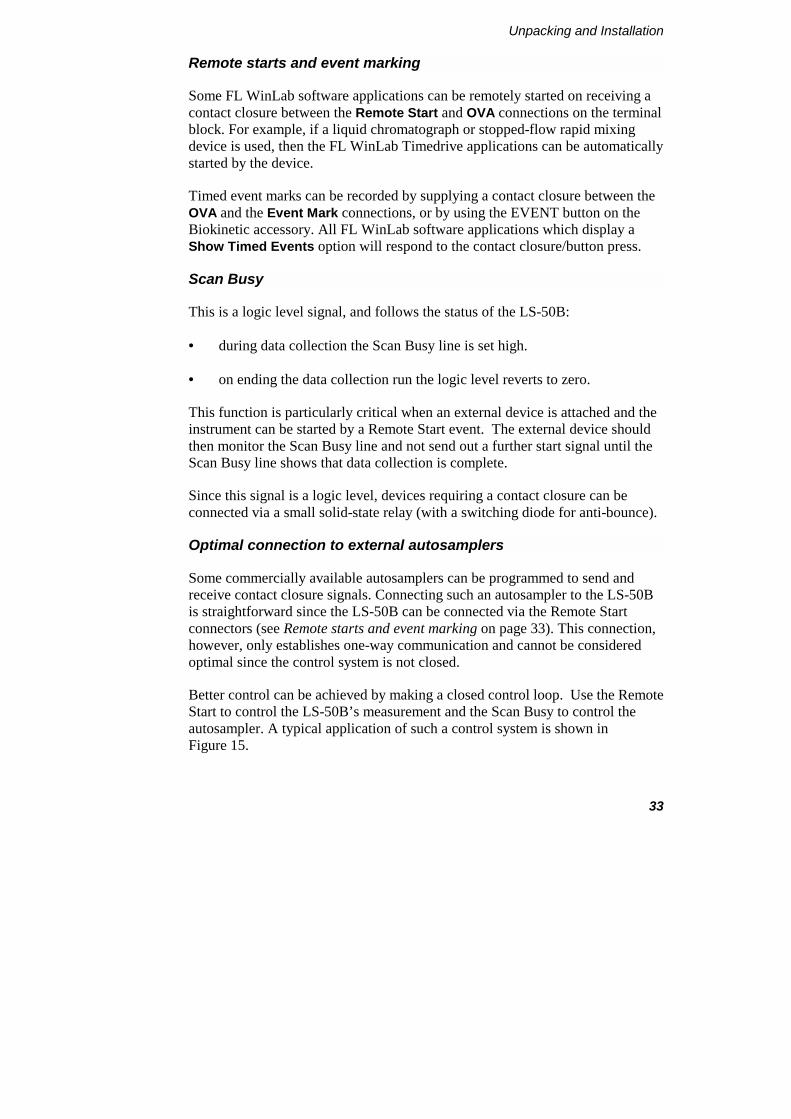
Inside the sample area door are two electrical control sockets for accessories, as shown in Figure 13. Note that the left-hand socket has 12 pins and the right-hand socket has 19 pins, so it is not possible to incorrectly connect accessory control plugs. Connecting specific accessories is described in the relevant sections of this manual.
Figure 13 Accessory electrical sockets

Unpacking and Installation
31
Remove the two dust covers before connecting accessories.
Rear panel connectors
On the left-hand side of the rear panel (viewed from the back) are two sockets labelled RS232C Controller and Autosampler, and an eight tag terminal block, as shown in Figure 14.
Figure 14 Rear panel electrical connections
LS-50B User’s Guide
32
The RS232C connection
The RS232C connection is used to communicate with your PC. Connect your LS-50B to your PC as follows:
1. Attach the anti-surge protector to the RS232C Controller socket of the LS-50B, securing it with the built-in screws.
2. Attach the RS232C cable, supplied, to the anti-surge protector.
3. Attach the 9-pin socket of the RS232C cable to an RS232C socket on the PC. Note which RS232C socket on the PC was used, as this information must be entered during installation of the FL WinLab software.
The Terminal block
The terminal block is used to provide analog signal output from the LS-50B, to initiate remote starts and to provide logic status signals for use with intelligent external systems.
To make a connection in the terminal block:
1. Insert a small screwdriver into the bottom of the terminal block and push upwards.
2. Feed the connecting wire into the hole at the top of the terminal block.
3. Remove the screwdriver. The wire is now firmly clamped.
Analog signal outputs
External signal integration devices, chart recorders, etc., can be connected to the analog outputs. One of the connecting wires (in an unbalanced system having one ground and one signal wire this must be the ground wire) must be connected to the OVA connection. The other wire can be connected to the required output, 1V, 10V or 10mV.
Unpacking and Installation
33
Remote starts and event marking
Some FL WinLab software applications can be remotely started on receiving a contact closure between the Remote Start and OVA connections on the terminal block. For example, if a liquid chromatograph or stopped-flow rapid mixing device is used, then the FL WinLab Timedrive applications can be automatically started by the device.
Timed event marks can be recorded by supplying a contact closure between the OVA and the Event Mark connections, or by using the EVENT button on the Biokinetic accessory. All FL WinLab software applications which display a Show Timed Events option will respond to the contact closure/button press.
Scan Busy
This is a logic level signal, and follows the status of the LS-50B:
• during data collection the Scan Busy line is set high.
• on ending the data collection run the logic level reverts to zero.
This function is particularly critical when an external device is attached and the instrument can be started by a Remote Start event. The external device should then monitor the Scan Busy line and not send out a further start signal until the Scan Busy line shows that data collection is complete.
Since this signal is a logic level, devices requiring a contact closure can be connected via a small solid-state relay (with a switching diode for anti-bounce).
Optimal connection to external autosamplers
Some commercially available autosamplers can be programmed to send and receive contact closure signals. Connecting such an autosampler to the LS-50B is straightforward since the LS-50B can be connected via the Remote Start connectors (see Remote starts and event marking on page 33). This connection, however, only establishes one-way communication and cannot be considered optimal since the control system is not closed.
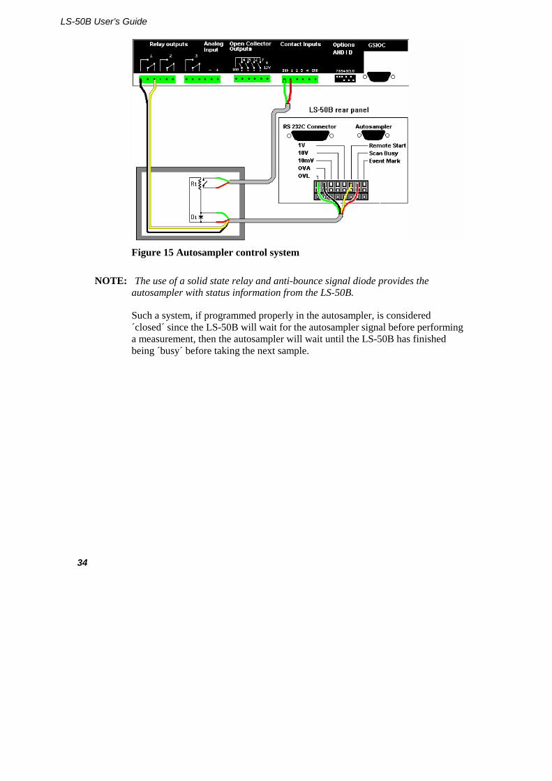
Better control can be achieved by making a closed control loop. Use the Remote Start to control the LS-50B’s measurement and the Scan Busy to control the autosampler. A typical application of such a control system is shown in Figure 15.
LS-50B User’s Guide
34
Figure 15 Autosampler control system
NOTE: The use of a solid state relay and anti-bounce signal diode provides the autosampler with status information from the LS-50B.
Such a system, if programmed properly in the autosampler, is considered ´closed´ since the LS-50B will wait for the autosampler signal before performing a measurement, then the autosampler will wait until the LS-50B has finished being ´busy´ before taking the next sample.
Unpacking and Installation
35
Switching on the LS-50B
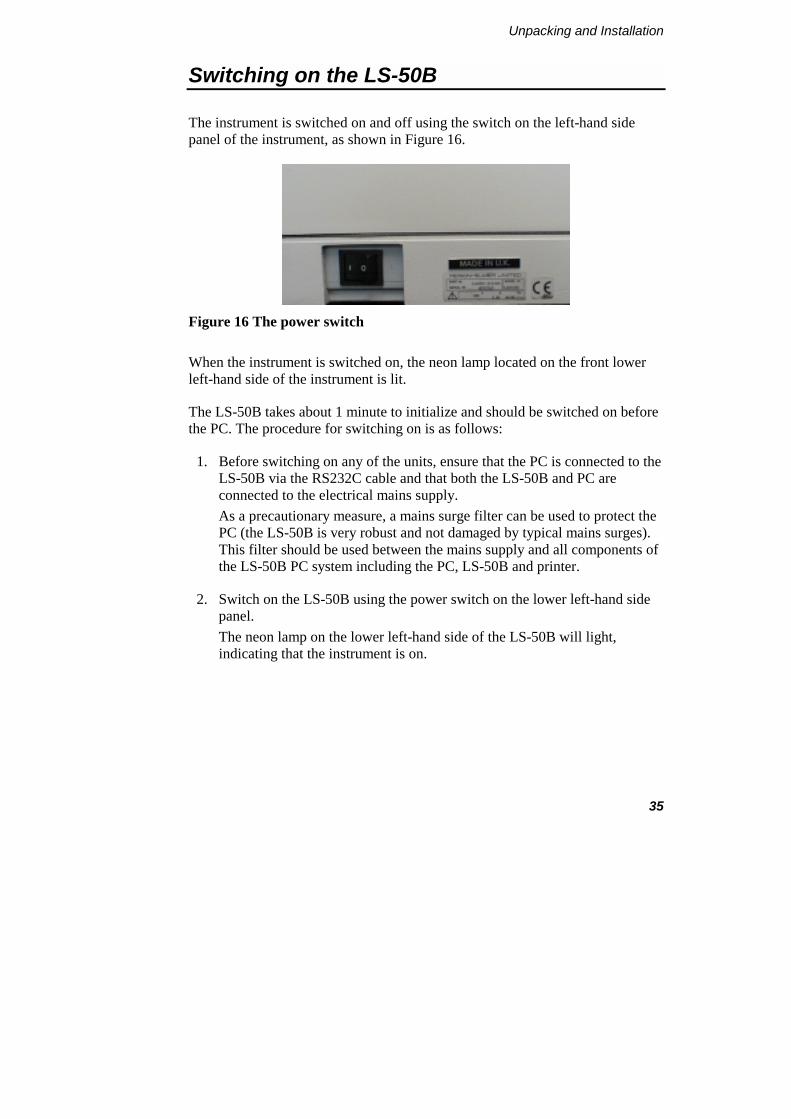
The instrument is switched on and off using the switch on the left-hand side panel of the instrument, as shown in Figure 16.
Figure 16 The power switch
When the instrument is switched on, the neon lamp located on the front lower left-hand side of the instrument is lit.
The LS-50B takes about 1 minute to initialize and should be switched on before the PC. The procedure for switching on is as follows:
1. Before switching on any of the units, ensure that the PC is connected to the LS-50B via the RS232C cable and that both the LS-50B and PC are connected to the electrical mains supply. As a precautionary measure, a mains surge filter can be used to protect the PC (the LS-50B is very robust and not damaged by typical mains surges). This filter should be used between the mains supply and all components of the LS-50B PC system including the PC, LS-50B and printer.
2. Switch on the LS-50B using the power switch on the lower left-hand side panel. The neon lamp on the lower left-hand side of the LS-50B will light, indicating that the instrument is on.

LS-50B User’s Guide
36
3. Switch on the PC.
4. When Windows has loaded, start the FL WinLab software.
NOTE: If the instrument has not yet finished initializing, this will be shown on the bottom-right side of FL WinLab Application dialogs. This will automatically reset to Online when the system is ready. At this point, data collection can proceed.
Accessories: Installation and Use 4

Accessories: Installation and Use
39
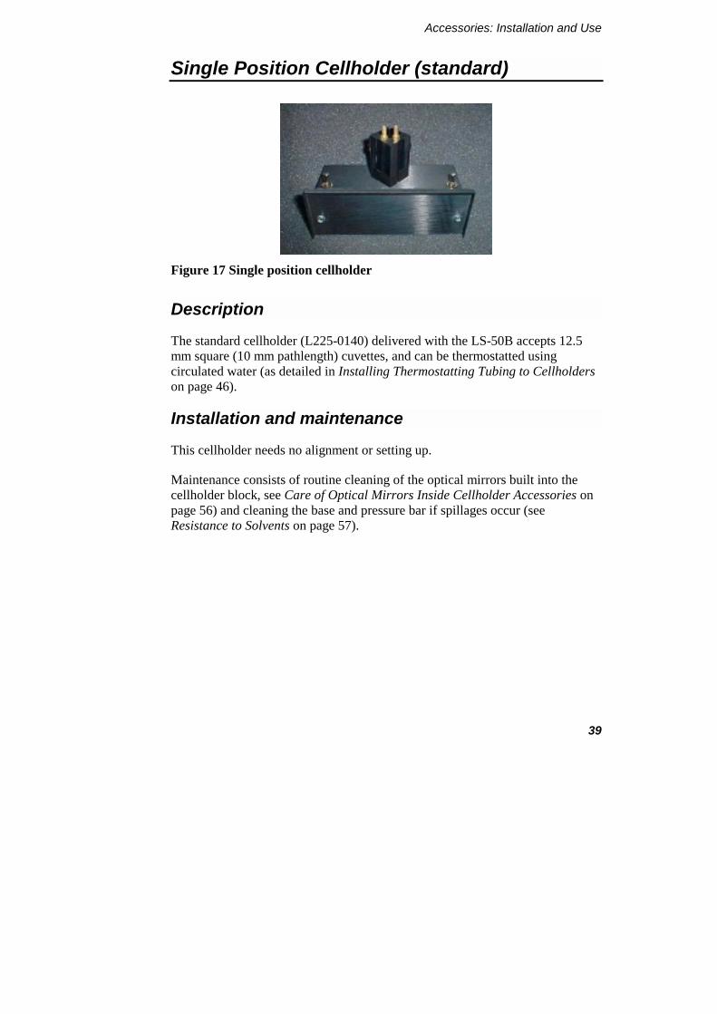
Single Position Cellholder (standard)
Figure 17 Single position cellholder
Description
The standard cellholder (L225-0140) delivered with the LS-50B accepts 12.5 mm square (10 mm pathlength) cuvettes, and can be thermostatted using circulated water (as detailed in Installing Thermostatting Tubing to Cellholders on page 46).
Installation and maintenance
This cellholder needs no alignment or setting up.
Maintenance consists of routine cleaning of the optical mirrors built into the cellholder block, see Care of Optical Mirrors Inside Cellholder Accessories on page 56) and cleaning the base and pressure bar if spillages occur (see Resistance to Solvents on page 57).
LS-50B User’s Guide
40
Stirred Single Position Cellholder
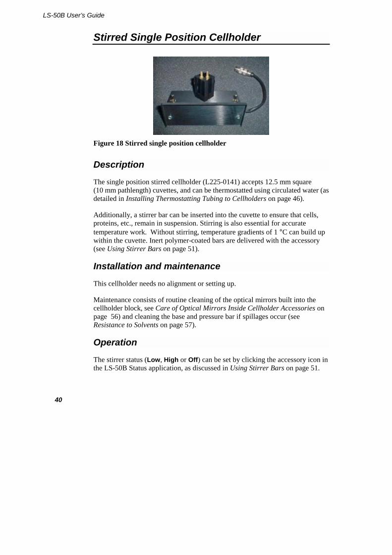
Figure 18 Stirred single position cellholder
Description
The single position stirred cellholder (L225-0141) accepts 12.5 mm square (10 mm pathlength) cuvettes, and can be thermostatted using circulated water (as detailed in Installing Thermostatting Tubing to Cellholders on page 46).
Additionally, a stirrer bar can be inserted into the cuvette to ensure that cells, proteins, etc., remain in suspension. Stirring is also essential for accurate temperature work. Without stirring, temperature gradients of 1 °C can build up within the cuvette. Inert polymer-coated bars are delivered with the accessory (see Using Stirrer Bars on page 51).
Installation and maintenance
This cellholder needs no alignment or setting up.
Maintenance consists of routine cleaning of the optical mirrors built into the cellholder block, see Care of Optical Mirrors Inside Cellholder Accessories on page 56) and cleaning the base and pressure bar if spillages occur (see Resistance to Solvents on page 57).
Operation
The stirrer status (Low, High or Off) can be set by clicking the accessory icon in the LS-50B Status application, as discussed in Using Stirrer Bars on page 51.
Accessories: Installation and Use
41
Stirred Four-Position Cellchanger
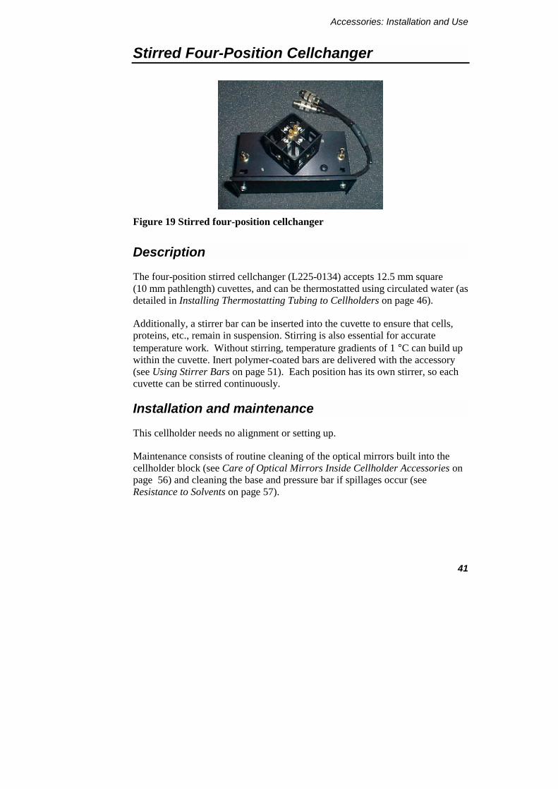
Figure 19 Stirred four-position cellchanger
Description
The four-position stirred cellchanger (L225-0134) accepts 12.5 mm square (10 mm pathlength) cuvettes, and can be thermostatted using circulated water (as detailed in Installing Thermostatting Tubing to Cellholders on page 46).
Additionally, a stirrer bar can be inserted into the cuvette to ensure that cells, proteins, etc., remain in suspension. Stirring is also essential for accurate temperature work. Without stirring, temperature gradients of 1 °C can build up within the cuvette. Inert polymer-coated bars are delivered with the accessory (see Using Stirrer Bars on page 51). Each position has its own stirrer, so each cuvette can be stirred continuously.
Installation and maintenance
This cellholder needs no alignment or setting up.
Maintenance consists of routine cleaning of the optical mirrors built into the cellholder block (see Care of Optical Mirrors Inside Cellholder Accessories on page 56) and cleaning the base and pressure bar if spillages occur (see Resistance to Solvents on page 57).
LS-50B User’s Guide
42
Biokinetics Accessory
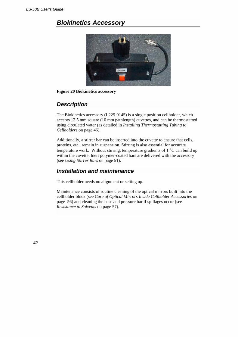
Figure 20 Biokinetics accessory
Description
The Biokinetics accessory (L225-0145) is a single position cellholder, which accepts 12.5 mm square (10 mm pathlength) cuvettes, and can be thermostatted using circulated water (as detailed in Installing Thermostatting Tubing to Cellholders on page 46).
Additionally, a stirrer bar can be inserted into the cuvette to ensure that cells, proteins, etc., remain in suspension. Stirring is also essential for accurate temperature work. Without stirring, temperature gradients of 1 °C can build up within the cuvette. Inert polymer-coated bars are delivered with the accessory (see Using Stirrer Bars on page 51).
Installation and maintenance
This cellholder needs no alignment or setting up.
Maintenance consists of routine cleaning of the optical mirrors built into the cellholder block (see Care of Optical Mirrors Inside Cellholder Accessories on page 56) and cleaning the base and pressure bar if spillages occur (see Resistance to Solvents on page 57).
Accessories: Installation and Use
43
Operation
The most important feature of the Biokinetics accessory is the temperature sensor. This is located in the block of the cellholder, and is used to report the temperature of the sample.
NOTE: The sensor should be calibrated using the FL WinLab LS-50B Status application.
FL WinLab applications which display graphical data (Scan, Timedrive, etc.) automatically record the temperature at the start of data collection in the result dataset header.
The Read application collects intensity, polarization or anisotropy data and saves this as a spreadsheet. If the Biokinetics accessory is fitted, then the temperature is saved simultaneously.
Another important feature is the event marker button on the front plate of the accessory. This is intended for identification of times when reagents are added to the cuvette. In most FL WinLab applications that collect time-dependent data, an option Show Timed Events is available. If this option is enabled, when you push the Event button, the Timed Event trace is modified to include a marker.
LS-50B User’s Guide
44
Screw-fitting Flowcell
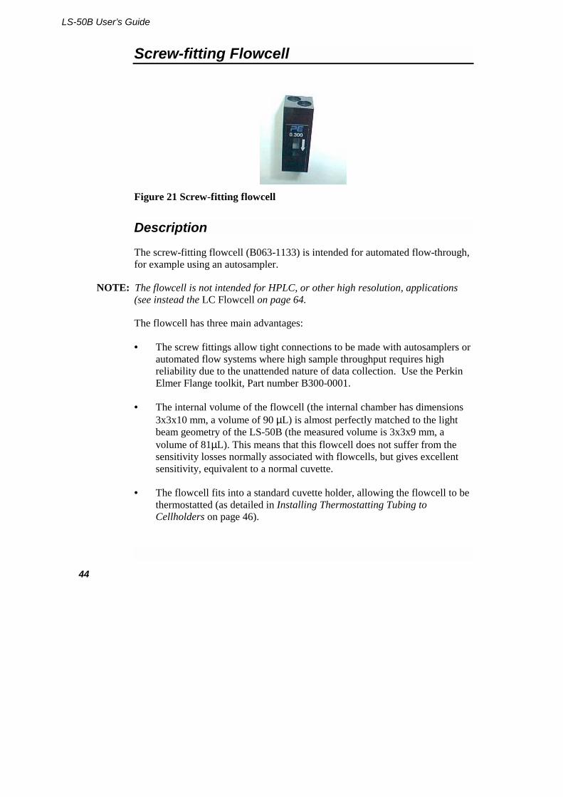
Figure 21 Screw-fitting flowcell
Description
The screw-fitting flowcell (B063-1133) is intended for automated flow-through, for example using an autosampler.
NOTE: The flowcell is not intended for HPLC, or other high resolution, applications (see instead the LC Flowcell on page 64.
The flowcell has three main advantages:
• The screw fittings allow tight connections to be made with autosamplers or automated flow systems where high sample throughput requires high reliability due to the unattended nature of data collection. Use the Perkin Elmer Flange toolkit, Part number B300-0001.
• The internal volume of the flowcell (the internal chamber has dimensions 3x3x10 mm, a volume of 90 µL) is almost perfectly matched to the light beam geometry of the LS-50B (the measured volume is 3x3x9 mm, a volume of 81µL). This means that this flowcell does not suffer from the sensitivity losses normally associated with flowcells, but gives excellent sensitivity, equivalent to a normal cuvette.
• The flowcell fits into a standard cuvette holder, allowing the flowcell to be thermostatted (as detailed in Installing Thermostatting Tubing to Cellholders on page 46).
Accessories: Installation and Use
45
Installation and maintenance
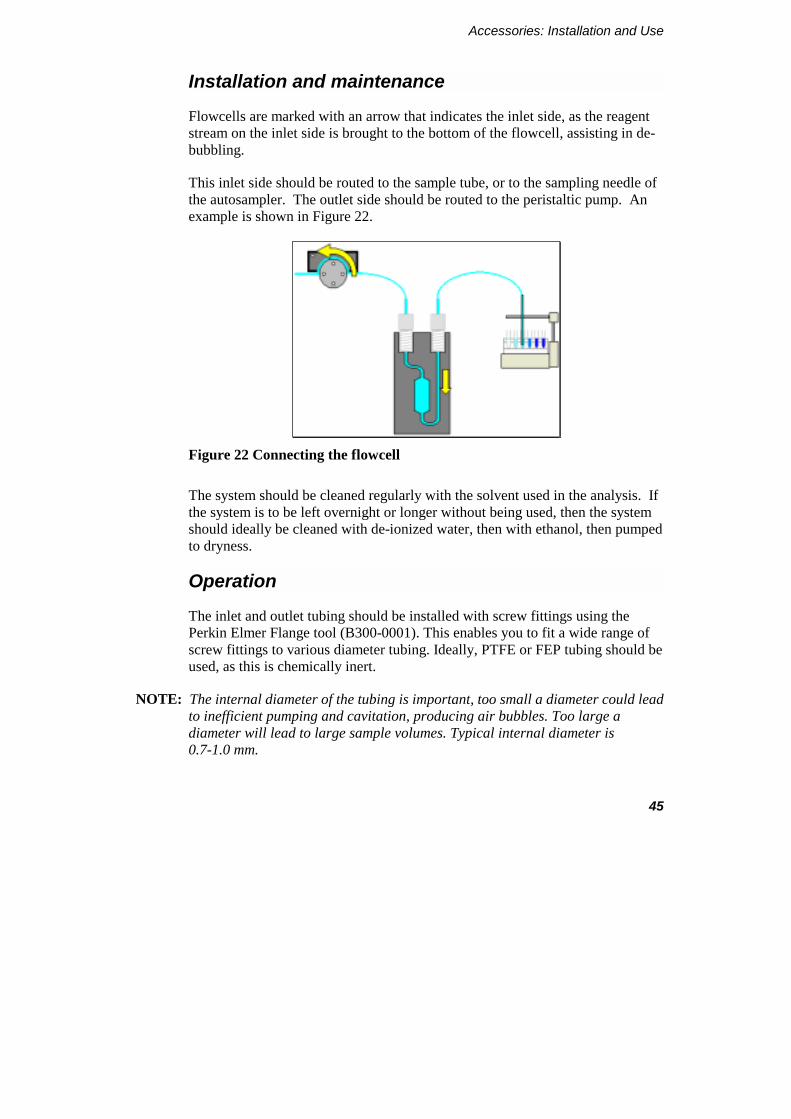
Flowcells are marked with an arrow that indicates the inlet side, as the reagent stream on the inlet side is brought to the bottom of the flowcell, assisting in de-bubbling.
This inlet side should be routed to the sample tube, or to the sampling needle of the autosampler. The outlet side should be routed to the peristaltic pump. An example is shown in Figure 22.
Figure 22 Connecting the flowcell
The system should be cleaned regularly with the solvent used in the analysis. If the system is to be left overnight or longer without being used, then the system should ideally be cleaned with de-ionized water, then with ethanol, then pumped to dryness.
Operation
The inlet and outlet tubing should be installed with screw fittings using the Perkin Elmer Flange tool (B300-0001). This enables you to fit a wide range of screw fittings to various diameter tubing. Ideally, PTFE or FEP tubing should be used, as this is chemically inert.
NOTE: The internal diameter of the tubing is important, too small a diameter could lead to inefficient pumping and cavitation, producing air bubbles. Too large a diameter will lead to large sample volumes. Typical internal diameter is 0.7-1.0 mm.
LS-50B User’s Guide
46
Installing Thermostatting Tubing to Cellholders
All cuvette holders supplied for use with the LS-50B are thermostattable using circulating water:
• The cuvette holders are made watertight with a sealant that is guaranteed up to 60 °C.
• Higher temperatures may make the sealant leak, in which case you should replace it with a suitable sealant with higher temperature specification.
• At temperatures below 15 °C, condensation may occur on the surfaces of the cuvette. If this is the case, either purge the sample area with dry air, or lead dry air onto the cuvette surfaces using tubing.
To fit the thermostatting tubing:
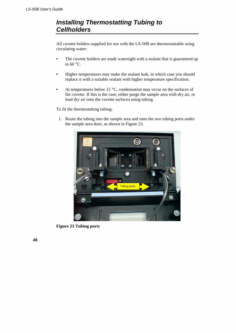
1. Route the tubing into the sample area and onto the two tubing ports under the sample area door, as shown in Figure 23.
Figure 23 Tubing ports
Tubing ports
Accessories: Installation and Use
47
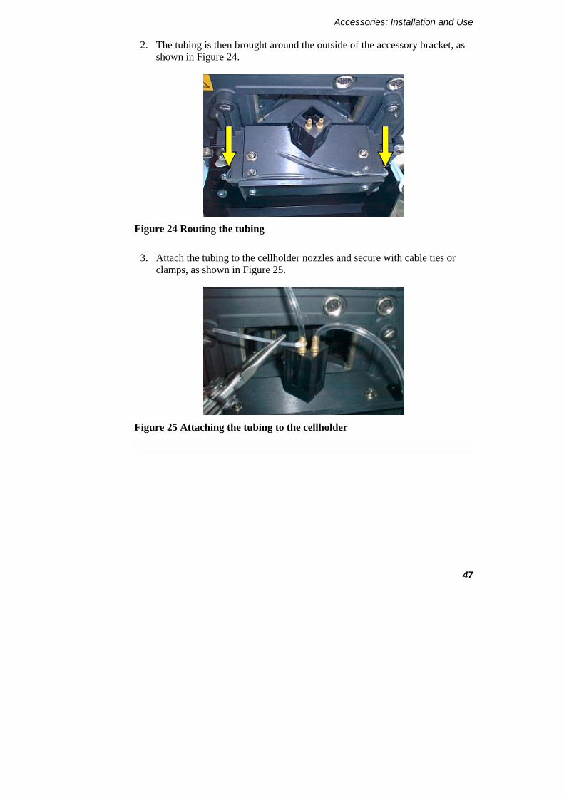
2. The tubing is then brought around the outside of the accessory bracket, as shown in Figure 24.
Figure 24 Routing the tubing
3. Attach the tubing to the cellholder nozzles and secure with cable ties or clamps, as shown in Figure 25.
Figure 25 Attaching the tubing to the cellholder
LS-50B User’s Guide
48
The four-position cellchanger
Installing tubing for the four-position cellchanger is slightly more complicated:
1. Disconnect the cellchanger, so it can be turned manually.
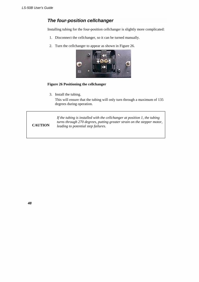
2. Turn the cellchanger to appear as shown in Figure 26.
Figure 26 Positioning the cellchanger
3. Install the tubing. This will ensure that the tubing will only turn through a maximum of 135 degrees during operation.
CAUTION
If the tubing is installed with the cellchanger at position 1, the tubing turns through 270 degrees, putting greater strain on the stepper motor, leading to potential step failures.
Accessories: Installation and Use
49
Using the Septum Injector
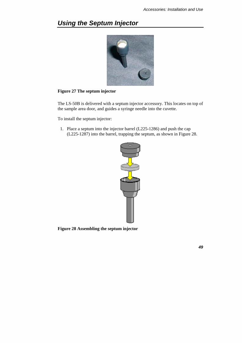
Figure 27 The septum injector
The LS-50B is delivered with a septum injector accessory. This locates on top of the sample area door, and guides a syringe needle into the cuvette.
To install the septum injector:
1. Place a septum into the injector barrel (L225-1286) and push the cap (L225-1287) into the barrel, trapping the septum, as shown in Figure 28.
Figure 28 Assembling the septum injector
LS-50B User’s Guide
50
2. Check that the cap fits securely. If not, the septum is probably too thick to allow the cap to grip the barrel adequately, and should be replaced.
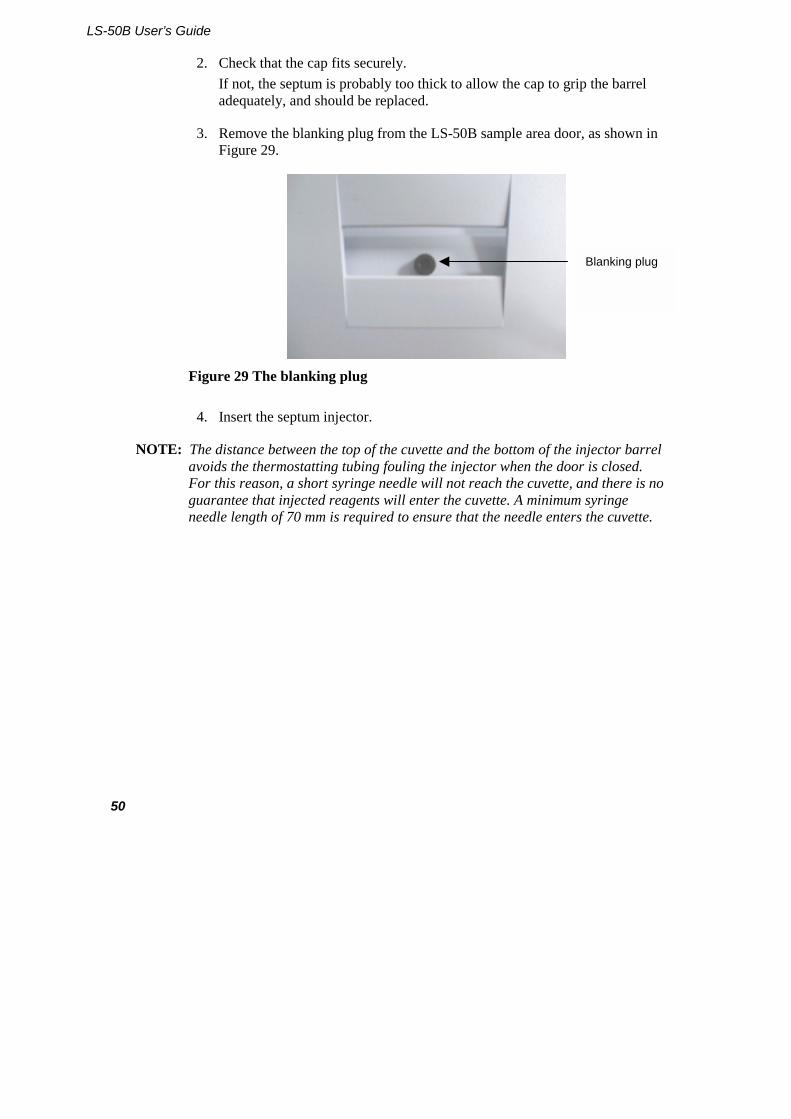
3. Remove the blanking plug from the LS-50B sample area door, as shown in Figure 29.
Figure 29 The blanking plug
4. Insert the septum injector.
NOTE: The distance between the top of the cuvette and the bottom of the injector barrel avoids the thermostatting tubing fouling the injector when the door is closed. For this reason, a short syringe needle will not reach the cuvette, and there is no guarantee that injected reagents will enter the cuvette. A minimum syringe needle length of 70 mm is required to ensure that the needle enters the cuvette.
Blanking plug
Accessories: Installation and Use
51
Using Stirrer Bars
Several accessories feature built-in stirring mechanisms.
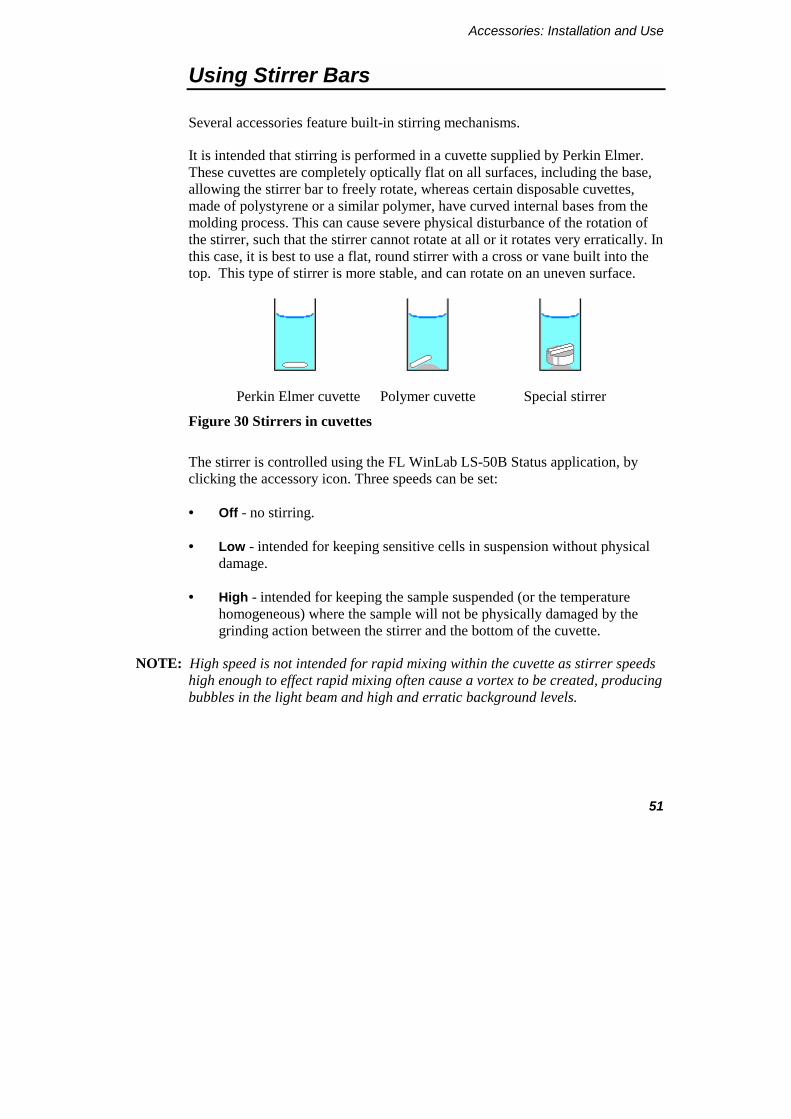
It is intended that stirring is performed in a cuvette supplied by Perkin Elmer. These cuvettes are completely optically flat on all surfaces, including the base, allowing the stirrer bar to freely rotate, whereas certain disposable cuvettes, made of polystyrene or a similar polymer, have curved internal bases from the molding process. This can cause severe physical disturbance of the rotation of the stirrer, such that the stirrer cannot rotate at all or it rotates very erratically. In this case, it is best to use a flat, round stirrer with a cross or vane built into the top. This type of stirrer is more stable, and can rotate on an uneven surface.
Perkin Elmer cuvette Polymer cuvette Special stirrer
Figure 30 Stirrers in cuvettes
The stirrer is controlled using the FL WinLab LS-50B Status application, by clicking the accessory icon. Three speeds can be set:
• Off - no stirring.
• Low - intended for keeping sensitive cells in suspension without physical damage.
• High - intended for keeping the sample suspended (or the temperature homogeneous) where the sample will not be physically damaged by the grinding action between the stirrer and the bottom of the cuvette.
NOTE: High speed is not intended for rapid mixing within the cuvette as stirrer speeds high enough to effect rapid mixing often cause a vortex to be created, producing bubbles in the light beam and high and erratic background levels.
LS-50B User’s Guide
52
Minimum volumes with various cuvette types
It is often desirable to minimize the volume of reagents used in the cuvette. This can be done using a smaller internal pathlength cuvette, with or without a stirring chamber underneath.
It should also be noted that cuvettes do not have to be totally filled, the liquid only has to cover the entire height of the light beam.
NOTE: However, failure to cover the height of the beam will cause light to be scattered off the underside of the meniscus, producing very high background signals.
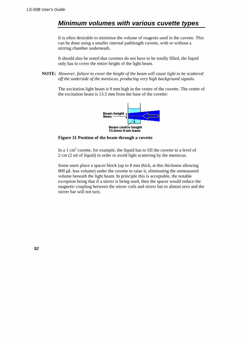
The excitation light beam is 9 mm high in the center of the cuvette. The center of the excitation beam is 13.5 mm from the base of the cuvette:
Figure 31 Position of the beam through a cuvette
In a 1 cm2 cuvette, for example, the liquid has to fill the cuvette to a level of 2 cm (2 ml of liquid) in order to avoid light scattering by the meniscus.
Some users place a spacer block (up to 8 mm thick, at this thickness allowing 800 µL less volume) under the cuvette to raise it, eliminating the unmeasured volume beneath the light beam. In principle this is acceptable, the notable exception being that if a stirrer is being used, then the spacer would reduce the magnetic coupling between the stirrer coils and stirrer bar to almost zero and the stirrer bar will not turn.

Accessories: Installation and Use
53
Semi-micro Cuvette and Holder
Figure 32 The semi-micro cuvette assembly
Description
The semi-micro cuvette and holder (L225-0139) enables you to measure smaller samples than with a standard cuvette. In spite of the decreased volume, however, sensitivity is not compromised since the LS-50B has a measured volume of 3 x 3 x 9 mm, which is smaller than the semi-micro cuvette's internal 5 mm pathlength.
Installation
The holder is simply inserted into a standard cellholder, as shown in Figure 33.
NOTE: The lip at the top, for removal of the holder, must be aligned away from you so that the lip does not contact the thermostatting nozzles, which would stop the holder from sitting properly in the cellholder.
Figure 33 Inserting the semi-micro cuvette
LS-50B User’s Guide
54
Stirred Semi-micro Cuvette
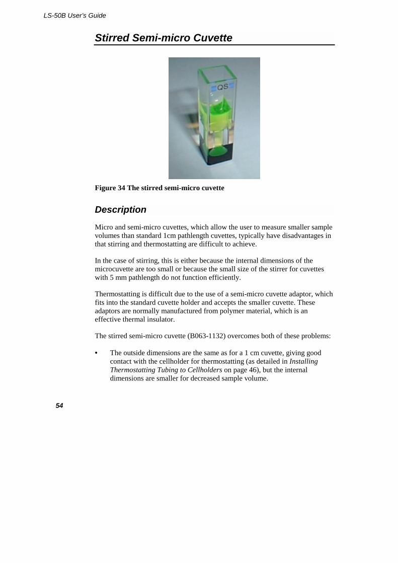
Figure 34 The stirred semi-micro cuvette
Description
Micro and semi-micro cuvettes, which allow the user to measure smaller sample volumes than standard 1cm pathlength cuvettes, typically have disadvantages in that stirring and thermostatting are difficult to achieve.
In the case of stirring, this is either because the internal dimensions of the microcuvette are too small or because the small size of the stirrer for cuvettes with 5 mm pathlength do not function efficiently.
Thermostatting is difficult due to the use of a semi-micro cuvette adaptor, which fits into the standard cuvette holder and accepts the smaller cuvette. These adaptors are normally manufactured from polymer material, which is an effective thermal insulator.
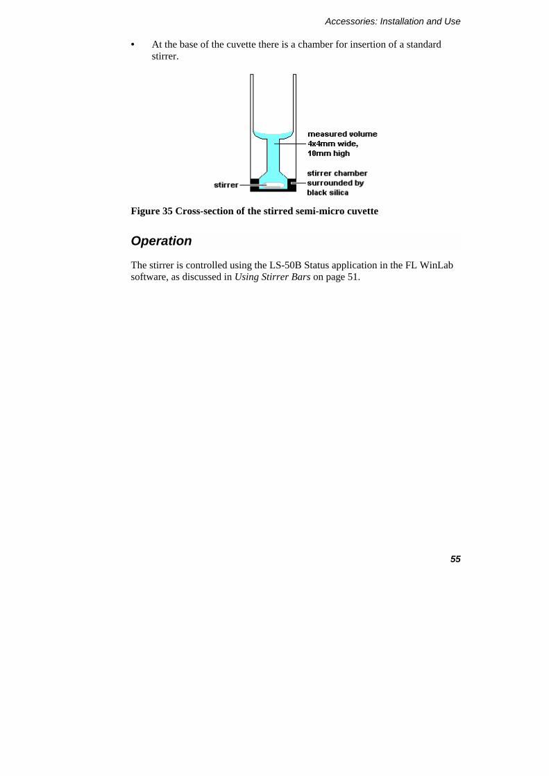
The stirred semi-micro cuvette (B063-1132) overcomes both of these problems:
• The outside dimensions are the same as for a 1 cm cuvette, giving good contact with the cellholder for thermostatting (as detailed in Installing Thermostatting Tubing to Cellholders on page 46), but the internal dimensions are smaller for decreased sample volume.
Accessories: Installation and Use
55
• At the base of the cuvette there is a chamber for insertion of a standard stirrer.
Figure 35 Cross-section of the stirred semi-micro cuvette
Operation
The stirrer is controlled using the LS-50B Status application in the FL WinLab software, as discussed in Using Stirrer Bars on page 51.

LS-50B User’s Guide
56
Care of Optical Mirrors Inside Cellholder Accessories
The mirrors built into cellholder accessories are used to reflect unabsorbed excitation light back into the sample to give a second pass at exciting the sample.
The emission mirror collects a portion of light emitted away from the instrument and reflects it back into the instrument.
Both mirrors together provide a 2.5-fold increase in signal, so in the worst case if both mirrors are totally corroded, they will not reflect light and the signal will decrease by a factor of 2.5-fold.
Additionally, if fluorescent material is allowed to build up on the mirrors, then background levels will increase significantly.
To prevent these possibilities, the mirrors should be regularly cleaned with methanol or a non-corrosive solvent.

Accessories: Installation and Use
57
Resistance to Solvents
The base of the cuvette holder block is manufactured from Delrin, a reasonably inert polymer. This is done to effect thermal isolation from the baseplate of the accessory for thermostatting. Although Delrin is resistant to most solvents, it can still be attacked by particularly aggressive solvents and acids such as 0.1 M perchloric acid.
The pressure bar which presses the cuvette back into the mirrored corner of the cuvette is also manufactured from Delrin.
To prevent damage, spillages should be washed with non-corrosive solvent or methanol.
If the base becomes attacked, the consequences are not severe unless it is totally dissolved, in which case the cuvette can fall through the base of the holder onto the metal baseplate. If the pressure bar is attacked, then the cuvette will not be located as firmly on the rear surfaces of the cellholder, possibly leading to unreproducible signals.
LS-50B User’s Guide
58
Sipper
Figure 36 The Sipper accessory
Description
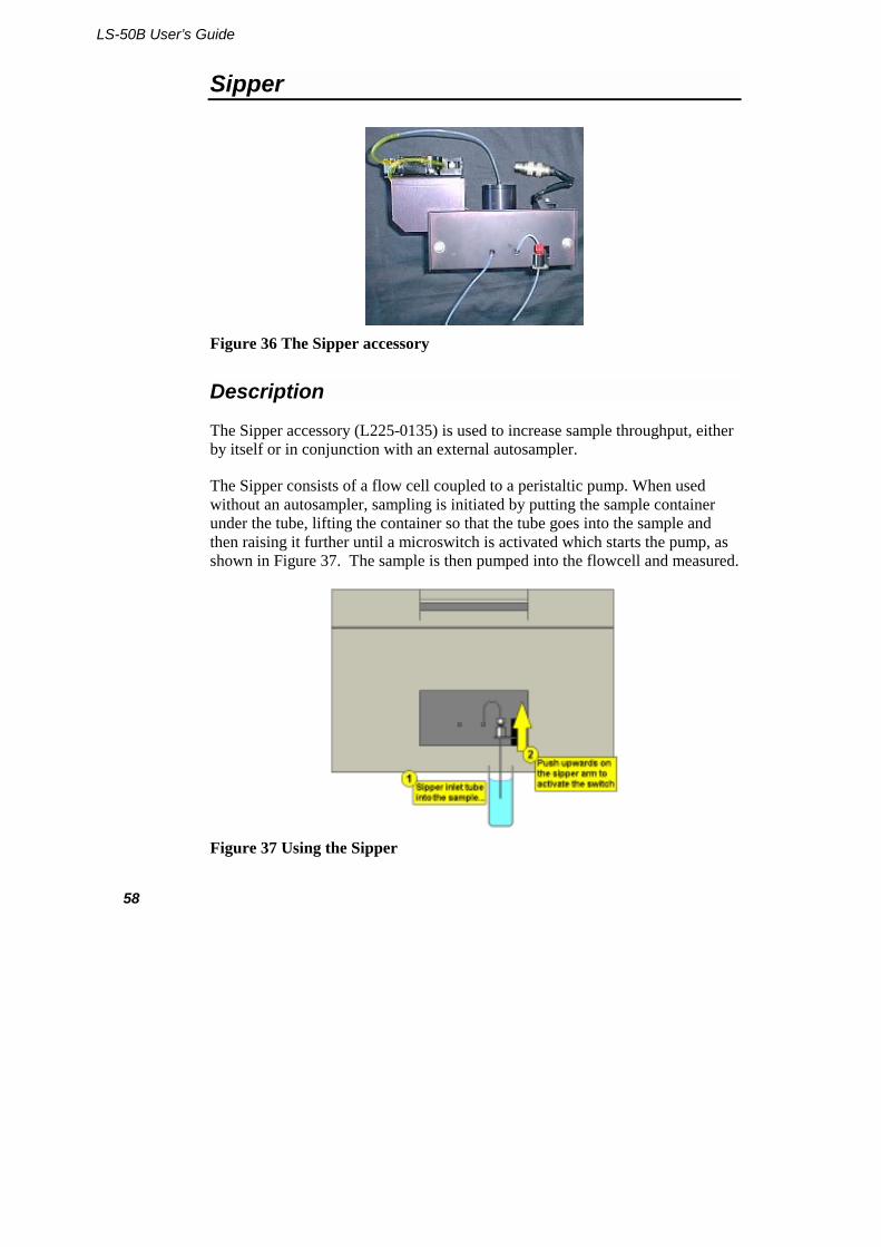
The Sipper accessory (L225-0135) is used to increase sample throughput, either by itself or in conjunction with an external autosampler.
The Sipper consists of a flow cell coupled to a peristaltic pump. When used without an autosampler, sampling is initiated by putting the sample container under the tube, lifting the container so that the tube goes into the sample and then raising it further until a microswitch is activated which starts the pump, as shown in Figure 37. The sample is then pumped into the flowcell and measured.
Figure 37 Using the Sipper

Accessories: Installation and Use
59
The measured volume of the sipper flowcell is approximately 1.5 x 1.5 x 10 mm. The maximum measured volume of the LS-50B (with wide open excitation and emission slits) is approximately 3 x 3 x 10 mm, so the absolute sensitivity when using the Sipper accessory would be around a factor of 4 times less sensitive than when using a cuvette. In spite of this loss, the Sipper accessory represents a much more sensitive option for high sampling throughput than for example a plate reader, where sensitivity would be at least a factor of 20 less sensitive (even for dedicated plate reader instruments).
Installation and maintenance
The Sipper accessory must be aligned before use, to ensure that the center of the flowcell sits correctly at the optical focus of the LS-50B. Installation is carried out as follows:
1. If the tubing is clamped in the switch lever, loosen the tubing clamp screw, as shown in Figure 38, and pull out the tubing.
Figure 38 The front of the Sipper
2. Loosen the two front plate fixing screws, as shown in Figure 38, and remove the front plate.
3. Loosen the two mount plate locking screws, as shown in Figure 39. This enables the mount plate to move freely during alignment.
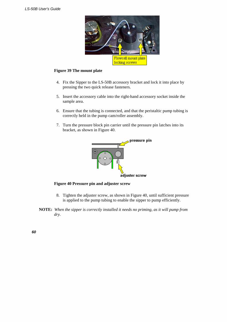
LS-50B User’s Guide
60
Figure 39 The mount plate
4. Fix the Sipper to the LS-50B accessory bracket and lock it into place by pressing the two quick release fasteners.
5. Insert the accessory cable into the right-hand accessory socket inside the sample area.
6. Ensure that the tubing is connected, and that the peristaltic pump tubing is correctly held in the pump cam/roller assembly.
7. Turn the pressure block pin carrier until the pressure pin latches into its bracket, as shown in Figure 40.
Figure 40 Pressure pin and adjuster screw
8. Tighten the adjuster screw, as shown in Figure 40, until sufficient pressure is applied to the pump tubing to enable the sipper to pump efficiently.
NOTE: When the sipper is correctly installed it needs no priming, as it will pump from dry.
Accessories: Installation and Use
61
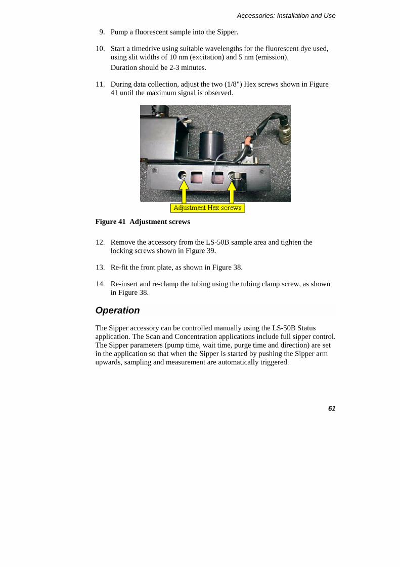
9. Pump a fluorescent sample into the Sipper.
10. Start a timedrive using suitable wavelengths for the fluorescent dye used, using slit widths of 10 nm (excitation) and 5 nm (emission). Duration should be 2-3 minutes.
11. During data collection, adjust the two (1/8") Hex screws shown in Figure 41 until the maximum signal is observed.
Figure 41 Adjustment screws
12. Remove the accessory from the LS-50B sample area and tighten the locking screws shown in Figure 39.
13. Re-fit the front plate, as shown in Figure 38.
14. Re-insert and re-clamp the tubing using the tubing clamp screw, as shown in Figure 38.
Operation
The Sipper accessory can be controlled manually using the LS-50B Status application. The Scan and Concentration applications include full sipper control. The Sipper parameters (pump time, wait time, purge time and direction) are set in the application so that when the Sipper is started by pushing the Sipper arm upwards, sampling and measurement are automatically triggered.
LS-50B User’s Guide
62
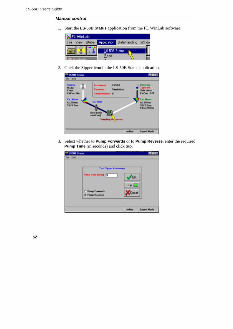
Manual control
1. Start the LS-50B Status application from the FL WinLab software.
2. Click the Sipper icon in the LS-50B Status application.
3. Select whether to Pump Forwards or to Pump Reverse, enter the required Pump Time (in seconds) and click Sip.
Accessories: Installation and Use
63
Scanning spectra
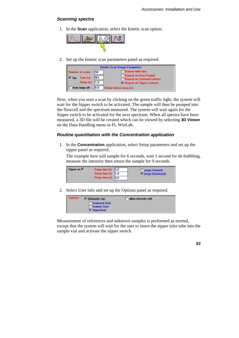
1. In the Scan application, select the kinetic scan option.
2. Set up the kinetic scan parameters panel as required.
Now, when you start a scan by clicking on the green traffic light, the system will wait for the Sipper switch to be activated. The sample will then be pumped into the flowcell and the spectrum measured. The system will wait again for the Sipper switch to be activated for the next spectrum. When all spectra have been measured, a 3D file will be created which can be viewed by selecting 3D Viewer on the Data Handling menu in FL WinLab.
Routine quantitation with the Concentration application
1. In the Concentration application, select Setup parameters and set up the sipper panel as required. The example here will sample for 6 seconds, wait 1 second for de-bubbling, measure the intensity then return the sample for 9 seconds.
2. Select User info and set up the Options panel as required.
Measurement of references and unknown samples is performed as normal, except that the system will wait for the user to insert the sipper inlet tube into the sample vial and activate the sipper switch.
LS-50B User’s Guide
64
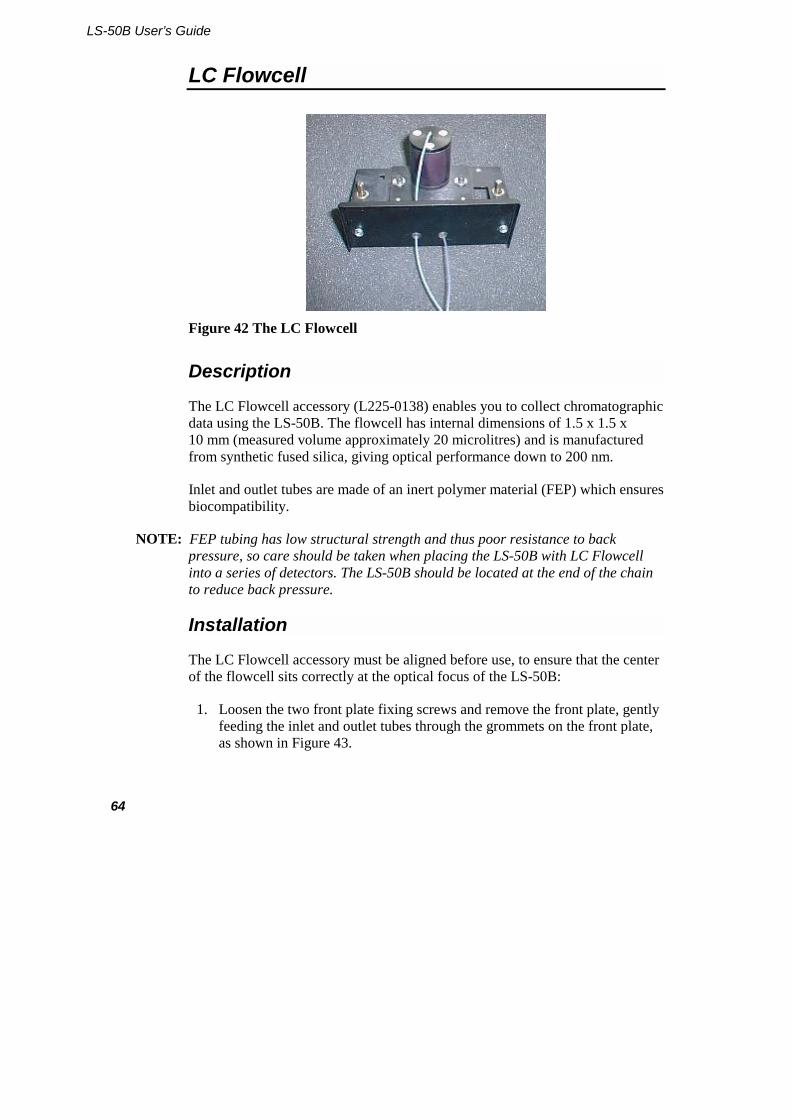
LC Flowcell
Figure 42 The LC Flowcell
Description
The LC Flowcell accessory (L225-0138) enables you to collect chromatographic data using the LS-50B. The flowcell has internal dimensions of 1.5 x 1.5 x 10 mm (measured volume approximately 20 microlitres) and is manufactured from synthetic fused silica, giving optical performance down to 200 nm.
Inlet and outlet tubes are made of an inert polymer material (FEP) which ensures biocompatibility.
NOTE: FEP tubing has low structural strength and thus poor resistance to back pressure, so care should be taken when placing the LS-50B with LC Flowcell into a series of detectors. The LS-50B should be located at the end of the chain to reduce back pressure.
Installation
The LC Flowcell accessory must be aligned before use, to ensure that the center of the flowcell sits correctly at the optical focus of the LS-50B:
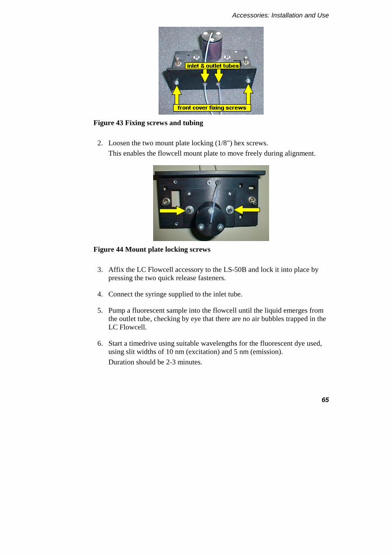
1. Loosen the two front plate fixing screws and remove the front plate, gently feeding the inlet and outlet tubes through the grommets on the front plate, as shown in Figure 43.
Accessories: Installation and Use
65
Figure 43 Fixing screws and tubing
2. Loosen the two mount plate locking (1/8") hex screws. This enables the flowcell mount plate to move freely during alignment.
Figure 44 Mount plate locking screws
3. Affix the LC Flowcell accessory to the LS-50B and lock it into place by pressing the two quick release fasteners.
4. Connect the syringe supplied to the inlet tube.
5. Pump a fluorescent sample into the flowcell until the liquid emerges from the outlet tube, checking by eye that there are no air bubbles trapped in the LC Flowcell.
6. Start a timedrive using suitable wavelengths for the fluorescent dye used, using slit widths of 10 nm (excitation) and 5 nm (emission). Duration should be 2-3 minutes.
LS-50B User’s Guide
66
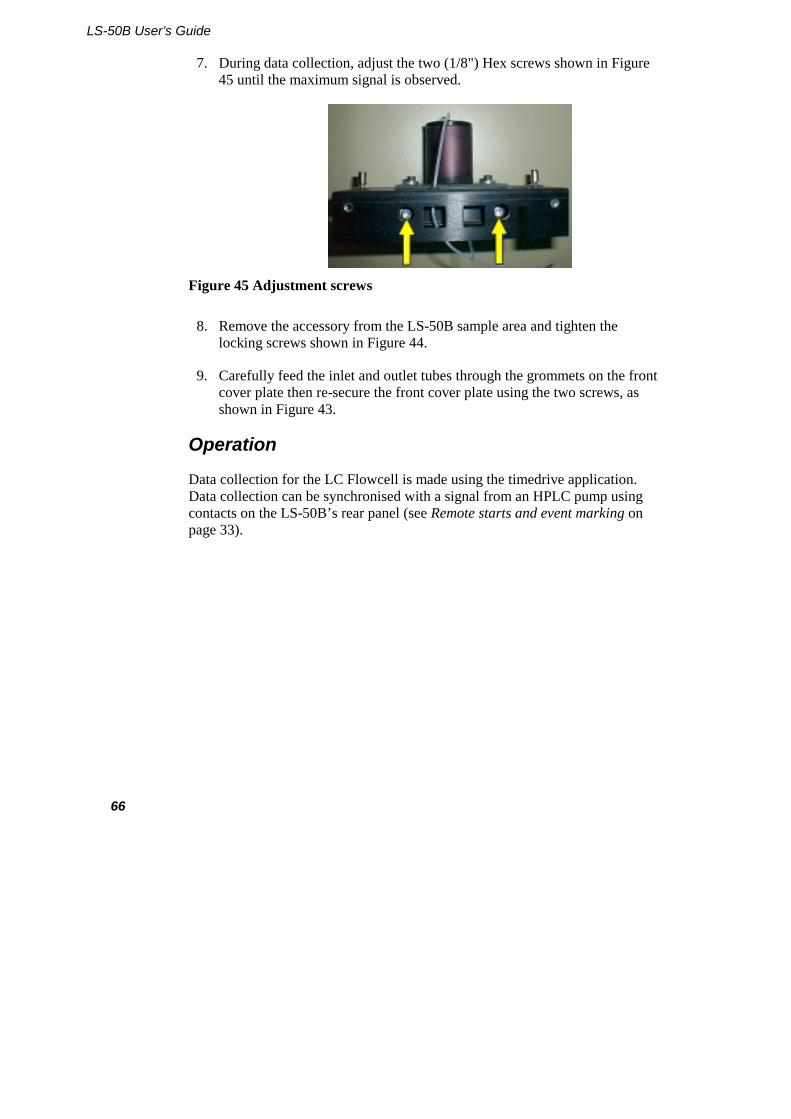
7. During data collection, adjust the two (1/8") Hex screws shown in Figure 45 until the maximum signal is observed.
Figure 45 Adjustment screws
8. Remove the accessory from the LS-50B sample area and tighten the locking screws shown in Figure 44.
9. Carefully feed the inlet and outlet tubes through the grommets on the front cover plate then re-secure the front cover plate using the two screws, as shown in Figure 43.
Operation
Data collection for the LC Flowcell is made using the timedrive application. Data collection can be synchronised with a signal from an HPLC pump using contacts on the LS-50B’s rear panel (see Remote starts and event marking on page 33).

Accessories: Installation and Use
67
Front Surface Accessory
Figure 46 The Front Surface accessory
Description
The Front Surface accessory (5212-3130) is used for the measurement of powders and flat samples such as papers, leaves, polymers, etc. It is also used in the life sciences for turbid samples where the sample cannot be diluted but gives severe quantitative problems due to light scattering.
The Front Surface accessory must be aligned to ensure correct sensitivity. Failure to do this could lead to a large loss of sensitivity. Furthermore, the process of alignment optimizes sensitivity to luminescence signals and minimizes the effect of light scattering.
LS-50B User’s Guide
68
Installation and maintenance
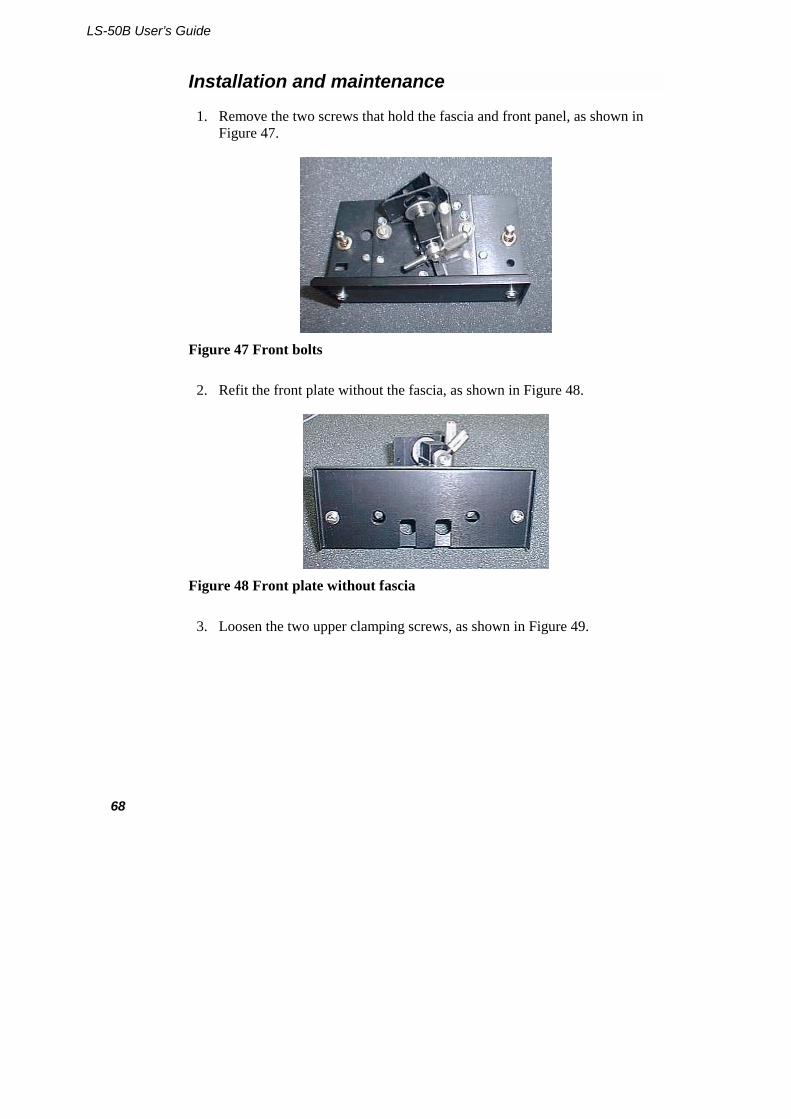
1. Remove the two screws that hold the fascia and front panel, as shown in Figure 47.
Figure 47 Front bolts
2. Refit the front plate without the fascia, as shown in Figure 48.
Figure 48 Front plate without fascia
3. Loosen the two upper clamping screws, as shown in Figure 49.
Accessories: Installation and Use
69
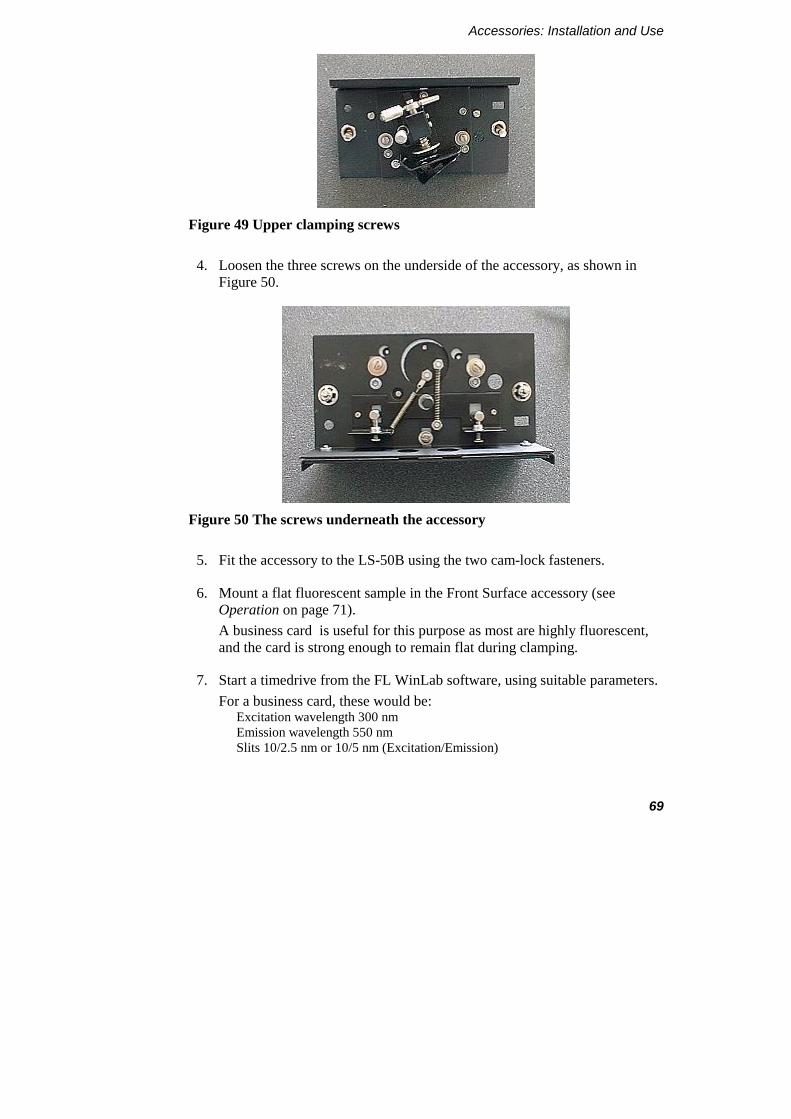
Figure 49 Upper clamping screws
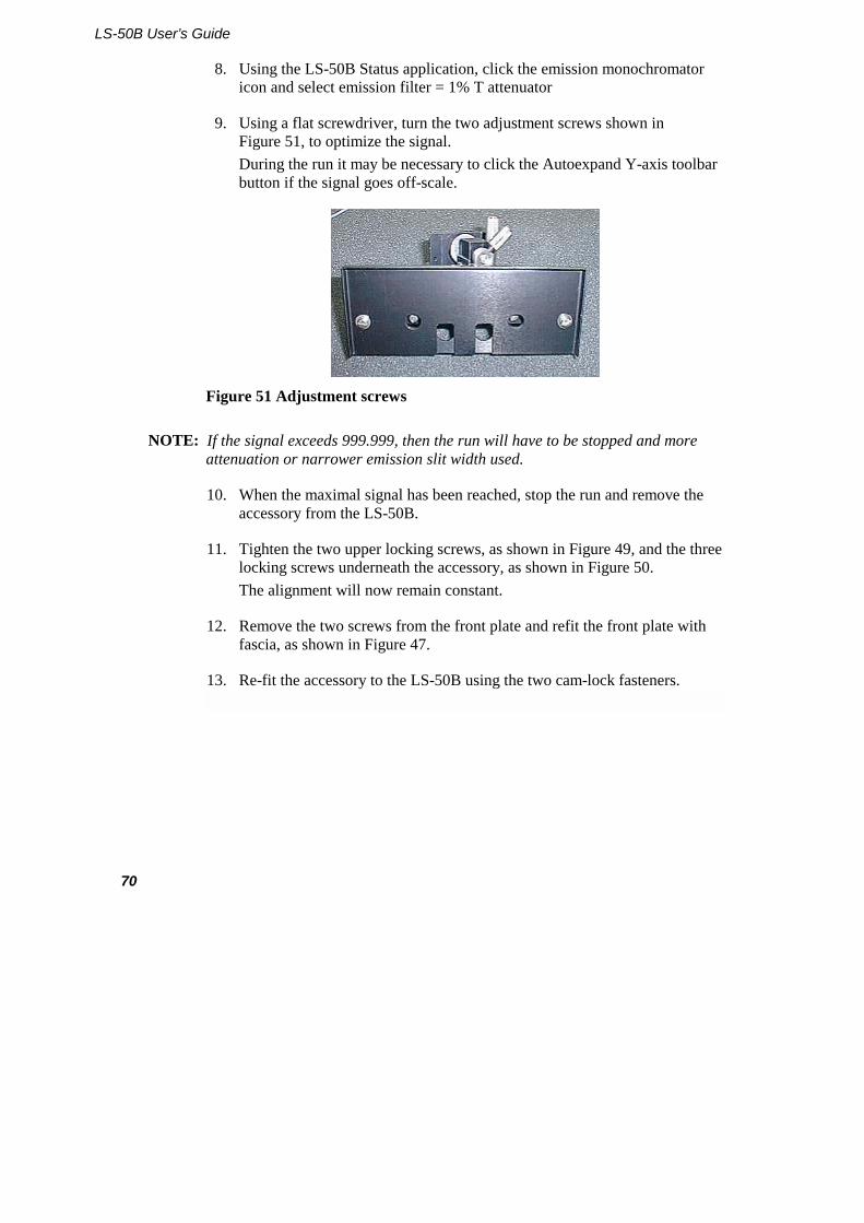
4. Loosen the three screws on the underside of the accessory, as shown in Figure 50.
Figure 50 The screws underneath the accessory
5. Fit the accessory to the LS-50B using the two cam-lock fasteners.
6. Mount a flat fluorescent sample in the Front Surface accessory (see Operation on page 71). A business card is useful for this purpose as most are highly fluorescent, and the card is strong enough to remain flat during clamping.
7. Start a timedrive from the FL WinLab software, using suitable parameters. For a business card, these would be:
Excitation wavelength 300 nm Emission wavelength 550 nm Slits 10/2.5 nm or 10/5 nm (Excitation/Emission)
LS-50B User’s Guide
70
8. Using the LS-50B Status application, click the emission monochromator icon and select emission filter = 1% T attenuator
9. Using a flat screwdriver, turn the two adjustment screws shown in Figure 51, to optimize the signal. During the run it may be necessary to click the Autoexpand Y-axis toolbar button if the signal goes off-scale.
Figure 51 Adjustment screws
NOTE: If the signal exceeds 999.999, then the run will have to be stopped and more attenuation or narrower emission slit width used.
10. When the maximal signal has been reached, stop the run and remove the accessory from the LS-50B.
11. Tighten the two upper locking screws, as shown in Figure 49, and the three locking screws underneath the accessory, as shown in Figure 50. The alignment will now remain constant.
12. Remove the two screws from the front plate and refit the front plate with fascia, as shown in Figure 47.
13. Re-fit the accessory to the LS-50B using the two cam-lock fasteners.
Accessories: Installation and Use
71
Operation
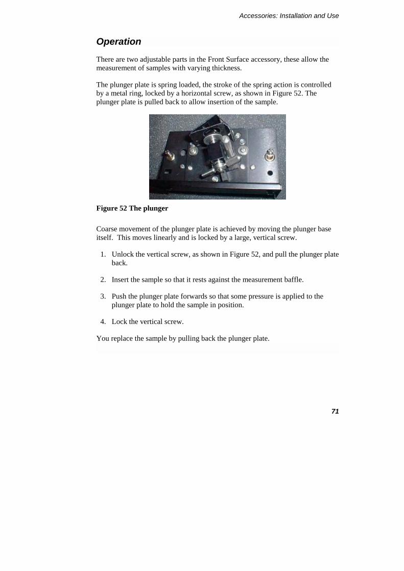
There are two adjustable parts in the Front Surface accessory, these allow the measurement of samples with varying thickness.
The plunger plate is spring loaded, the stroke of the spring action is controlled by a metal ring, locked by a horizontal screw, as shown in Figure 52. The plunger plate is pulled back to allow insertion of the sample.
Figure 52 The plunger
Coarse movement of the plunger plate is achieved by moving the plunger base itself. This moves linearly and is locked by a large, vertical screw.
1. Unlock the vertical screw, as shown in Figure 52, and pull the plunger plate back.
2. Insert the sample so that it rests against the measurement baffle.
3. Push the plunger plate forwards so that some pressure is applied to the plunger plate to hold the sample in position.
4. Lock the vertical screw.
You replace the sample by pulling back the plunger plate.
LS-50B User’s Guide
72
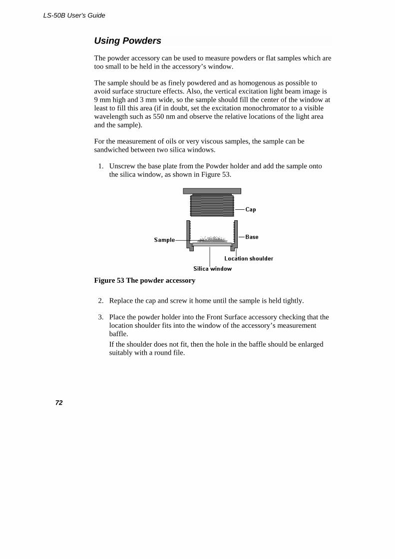
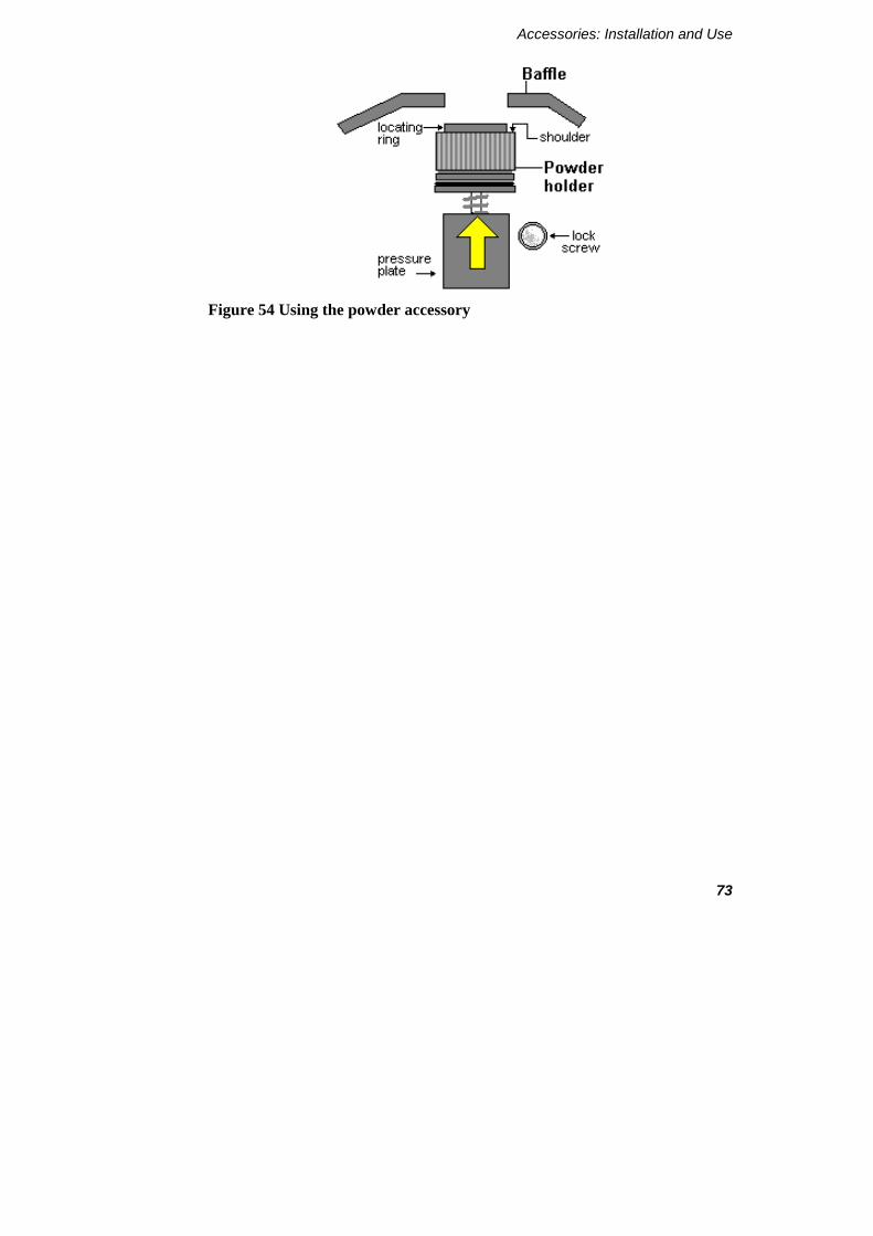
Using Powders
The powder accessory can be used to measure powders or flat samples which are too small to be held in the accessory’s window.
The sample should be as finely powdered and as homogenous as possible to avoid surface structure effects. Also, the vertical excitation light beam image is 9 mm high and 3 mm wide, so the sample should fill the center of the window at least to fill this area (if in doubt, set the excitation monochromator to a visible wavelength such as 550 nm and observe the relative locations of the light area and the sample).
For the measurement of oils or very viscous samples, the sample can be sandwiched between two silica windows.
1. Unscrew the base plate from the Powder holder and add the sample onto the silica window, as shown in Figure 53.
Figure 53 The powder accessory
2. Replace the cap and screw it home until the sample is held tightly.
3. Place the powder holder into the Front Surface accessory checking that the location shoulder fits into the window of the accessory’s measurement baffle. If the shoulder does not fit, then the hole in the baffle should be enlarged suitably with a round file.
Accessories: Installation and Use
73
Figure 54 Using the powder accessory
LS-50B User’s Guide
74
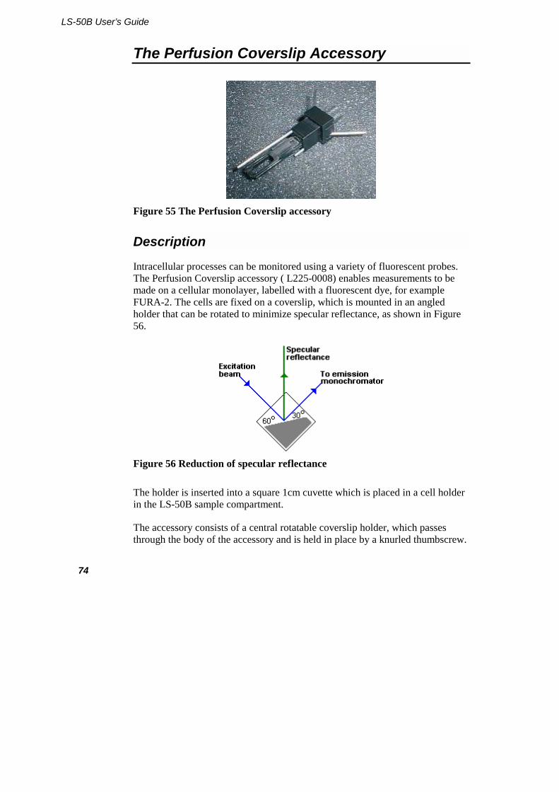
The Perfusion Coverslip Accessory
Figure 55 The Perfusion Coverslip accessory
Description
Intracellular processes can be monitored using a variety of fluorescent probes. The Perfusion Coverslip accessory ( L225-0008) enables measurements to be made on a cellular monolayer, labelled with a fluorescent dye, for example FURA-2. The cells are fixed on a coverslip, which is mounted in an angled holder that can be rotated to minimize specular reflectance, as shown in Figure 56.
Figure 56 Reduction of specular reflectance
The holder is inserted into a square 1cm cuvette which is placed in a cell holder in the LS-50B sample compartment.
The accessory consists of a central rotatable coverslip holder, which passes through the body of the accessory and is held in place by a knurled thumbscrew.

Accessories: Installation and Use
75
The body of the accessory has two built-in stainless steel tubes (and a third hole to allow another stainless steel tube to be added), as shown in Figure 57.
Figure 57 The parts of the accessory
Depending on the type of cellholder used, the sample can be stirred and thermostatted. Perfusion can be carried out by pumping buffer into and out of the accessory with different flow rates, as shown in Figure 58.
Figure 58 A buffered system
LS-50B User’s Guide
76
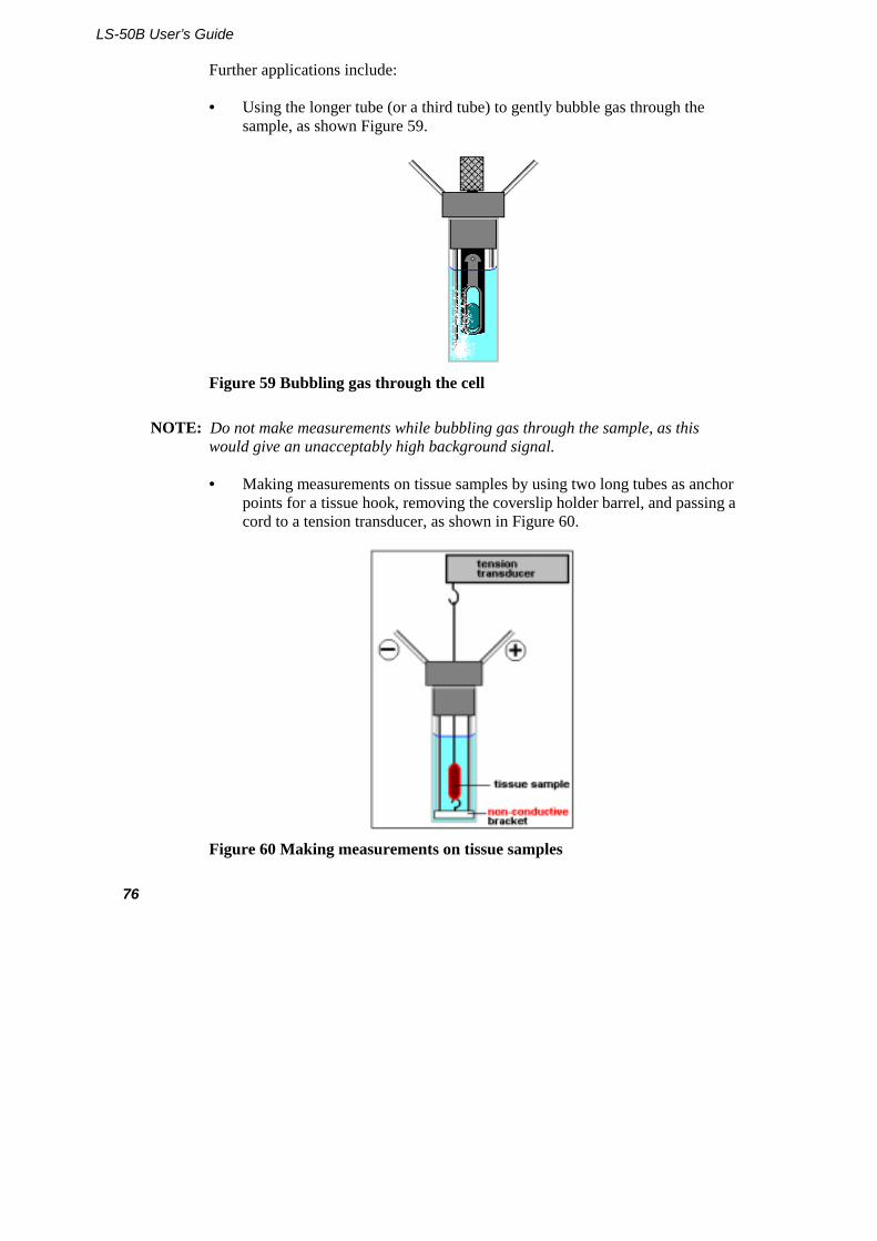
Further applications include:
• Using the longer tube (or a third tube) to gently bubble gas through the sample, as shown Figure 59.
Figure 59 Bubbling gas through the cell
NOTE: Do not make measurements while bubbling gas through the sample, as this would give an unacceptably high background signal.
• Making measurements on tissue samples by using two long tubes as anchor points for a tissue hook, removing the coverslip holder barrel, and passing a cord to a tension transducer, as shown in Figure 60.
Figure 60 Making measurements on tissue samples

Accessories: Installation and Use
77
Installation
1. Release the clip from the bottom of the coverslip accessory.
2. Slide the coverslip into place and reposition the clip.
3. If a magnetic stirrer is to be used, place this in the cuvette.
4. Insert the coverslip accessory into the cuvette.
5. If required, connect pump tubing to the two stainless steel tubes.
6. Close the sample compartment door and proceed with the analysis.
LS-50B User’s Guide
78
Plate Reader
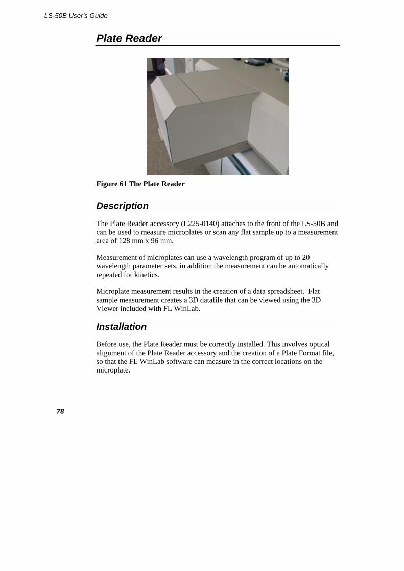
Figure 61 The Plate Reader
Description
The Plate Reader accessory (L225-0140) attaches to the front of the LS-50B and can be used to measure microplates or scan any flat sample up to a measurement area of 128 mm x 96 mm.
Measurement of microplates can use a wavelength program of up to 20 wavelength parameter sets, in addition the measurement can be automatically repeated for kinetics.
Microplate measurement results in the creation of a data spreadsheet. Flat sample measurement creates a 3D datafile that can be viewed using the 3D Viewer included with FL WinLab.
Installation
Before use, the Plate Reader must be correctly installed. This involves optical alignment of the Plate Reader accessory and the creation of a Plate Format file, so that the FL WinLab software can measure in the correct locations on the microplate.
Accessories: Installation and Use
79
In order to perform the optical alignment, a small (~4 cm square) flat mirror and a dentist’s mirror should be used.
1. Open the LS-50B top cover, as described in Removing the Main Cover on page 172.
2. Switch off the HT supply to the photomultiplier, as shown in Figure 62.
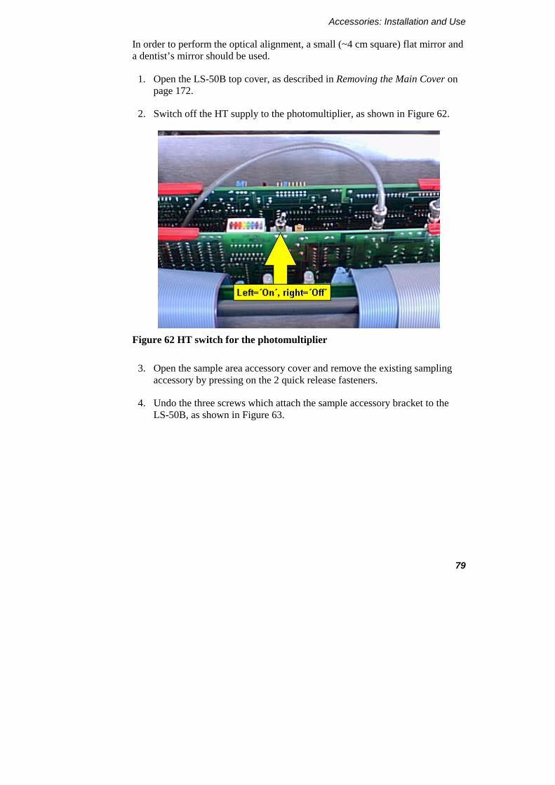
Figure 62 HT switch for the photomultiplier
3. Open the sample area accessory cover and remove the existing sampling accessory by pressing on the 2 quick release fasteners.
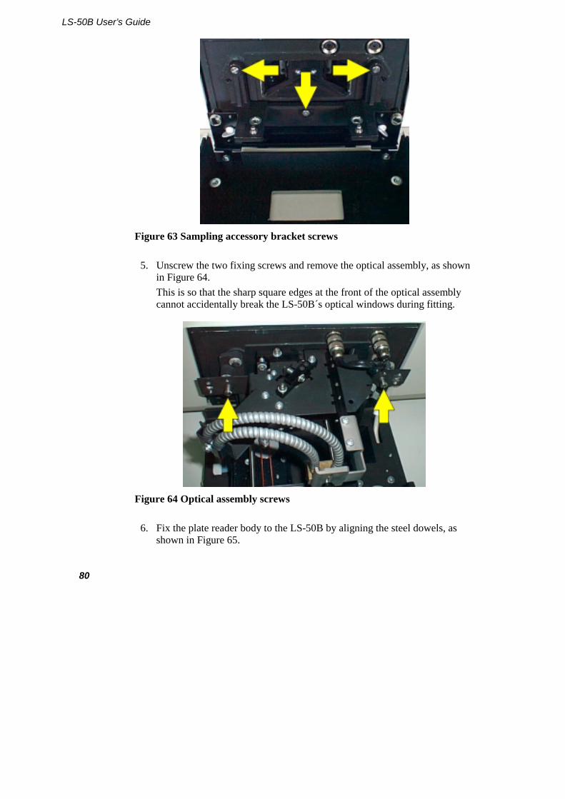
4. Undo the three screws which attach the sample accessory bracket to the LS-50B, as shown in Figure 63.
LS-50B User’s Guide
80
Figure 63 Sampling accessory bracket screws
5. Unscrew the two fixing screws and remove the optical assembly, as shown in Figure 64. This is so that the sharp square edges at the front of the optical assembly cannot accidentally break the LS-50B´s optical windows during fitting.
Figure 64 Optical assembly screws
6. Fix the plate reader body to the LS-50B by aligning the steel dowels, as shown in Figure 65.

Accessories: Installation and Use
81
Figure 65 Locating dowels
7. Tighten the three screws that secure the Plate Reader to the LS-50B, as shown in Figure 66.
Figure 66 Plate Reader screws
8. Attach the optical assembly to the Plate Reader and tighten the two screws which secure it, as shown in Figure 67.
LS-50B User’s Guide
82
Figure 67 Attaching the optical assembly
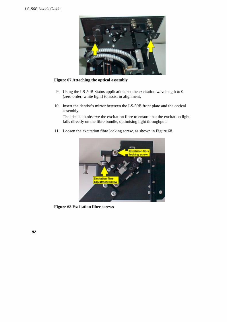
9. Using the LS-50B Status application, set the excitation wavelength to 0 (zero order, white light) to assist in alignment.
10. Insert the dentist’s mirror between the LS-50B front plate and the optical assembly. The idea is to observe the excitation fibre to ensure that the excitation light falls directly on the fibre bundle, optimising light throughput.
11. Loosen the excitation fibre locking screw, as shown in Figure 68.
Figure 68 Excitation fibre screws
Accessories: Installation and Use
83
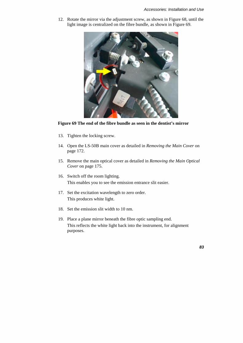
12. Rotate the mirror via the adjustment screw, as shown in Figure 68, until the light image is centralized on the fibre bundle, as shown in Figure 69.
Figure 69 The end of the fibre bundle as seen in the dentist’s mirror
13. Tighten the locking screw.
14. Open the LS-50B main cover as detailed in Removing the Main Cover on page 172.
15. Remove the main optical cover as detailed in Removing the Main Optical Cover on page 175.
16. Switch off the room lighting. This enables you to see the emission entrance slit easier.
17. Set the excitation wavelength to zero order. This produces white light.
18. Set the emission slit width to 10 nm.
19. Place a plane mirror beneath the fibre optic sampling end. This reflects the white light back into the instrument, for alignment purposes.
LS-50B User’s Guide
84
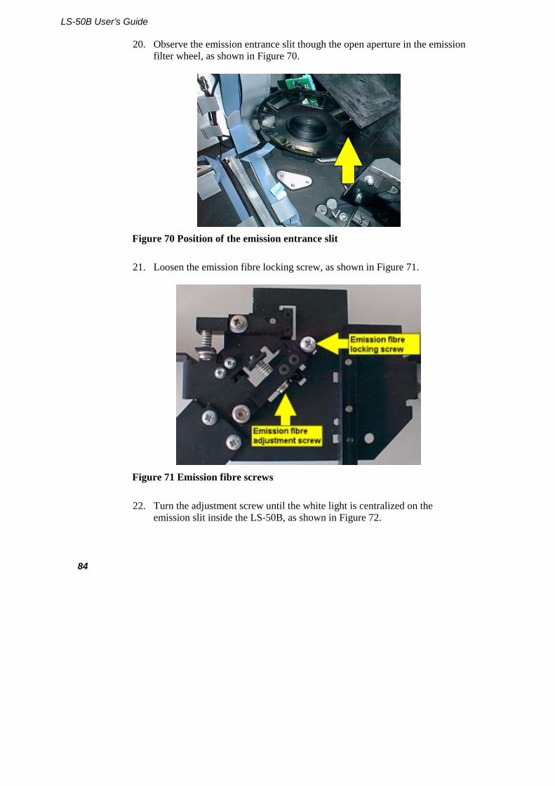
20. Observe the emission entrance slit though the open aperture in the emission filter wheel, as shown in Figure 70.
Figure 70 Position of the emission entrance slit
21. Loosen the emission fibre locking screw, as shown in Figure 71.
Figure 71 Emission fibre screws
22. Turn the adjustment screw until the white light is centralized on the emission slit inside the LS-50B, as shown in Figure 72.
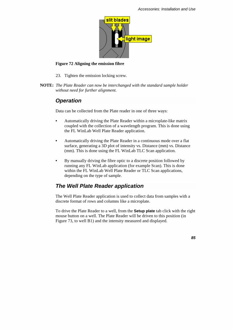
Accessories: Installation and Use
85
Figure 72 Aligning the emission fibre
23. Tighten the emission locking screw.
NOTE: The Plate Reader can now be interchanged with the standard sample holder without need for further alignment.
Operation
Data can be collected from the Plate reader in one of three ways:
• Automatically driving the Plate Reader within a microplate-like matrix coupled with the collection of a wavelength program. This is done using the FL WinLab Well Plate Reader application.
• Automatically driving the Plate Reader in a continuous mode over a flat surface, generating a 3D plot of intensity vs. Distance (mm) vs. Distance (mm). This is done using the FL WinLab TLC Scan application.
• By manually driving the fibre optic to a discrete position followed by running any FL WinLab application (for example Scan). This is done within the FL WinLab Well Plate Reader or TLC Scan applications, depending on the type of sample.
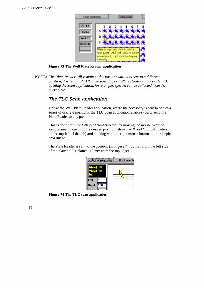
The Well Plate Reader application
The Well Plate Reader application is used to collect data from samples with a discrete format of rows and columns like a microplate.
To drive the Plate Reader to a well, from the Setup plate tab click with the right mouse button on a well. The Plate Reader will be driven to this position (in Figure 73, to well B1) and the intensity measured and displayed.
LS-50B User’s Guide
86
Figure 73 The Well Plate Reader application
NOTE: The Plate Reader will remain at this position until it is sent to a different position, it is sent to Park/Datum position, or a Plate Reader run is started. By opening the Scan application, for example, spectra can be collected from the microplate.
The TLC Scan application
Unlike the Well Plate Reader application, where the accessory is sent to one of a series of discrete positions, the TLC Scan application enables you to send the Plate Reader to any position.
This is done from the Setup parameters tab, by moving the mouse over the sample area image until the desired position (shown as X and Y in millimeters on the top left of the tab) and clicking with the right mouse button on the sample area image.
The Plate Reader is sent to the position (in Figure 74, 20 mm from the left side of the plate holder platten, 10 mm from the top edge).
Figure 74 The TLC scan application
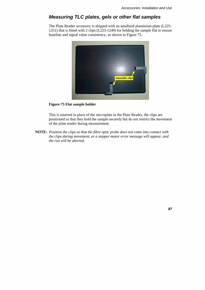
Accessories: Installation and Use
87
Measuring TLC plates, gels or other flat samples
The Plate Reader accessory is shipped with an anodized aluminium plate (L225-1251) that is fitted with 2 clips (L225-1249) for holding the sample flat to ensure baseline and signal value consistency, as shown in Figure 75.
Figure 75 Flat sample holder
This is inserted in place of the microplate in the Plate Reader, the clips are positioned so that they hold the sample securely but do not restrict the movement of the plate reader during measurement.
NOTE: Position the clips so that the fibre optic probe does not come into contact with the clips during movement, or a stepper motor error message will appear, and the run will be aborted.
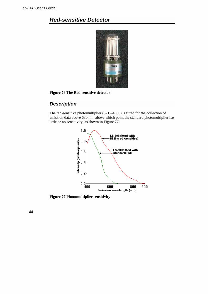
LS-50B User’s Guide
88
Red-sensitive Detector
Figure 76 The Red-sensitive detector
Description
The red-sensitive photomultiplier (5212-4966) is fitted for the collection of emission data above 630 nm, above which point the standard photomultiplier has little or no sensitivity, as shown in Figure 77.
Figure 77 Photomultiplier sensitivity

Accessories: Installation and Use
89
Installation
The photomultiplier installation procedure is detailed in Changing the photomultiplier on page 187.
NOTE: In order to obtain corrected emission spectra, the correction factor spectrum will have to be collected specifically for the red-sensitive photomultiplier. Data obtained using the standard photomultiplier is not applicable.
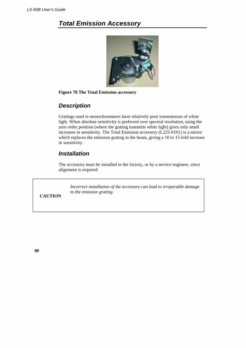
LS-50B User’s Guide
90
Total Emission Accessory
Figure 78 The Total Emission accessory
Description
Gratings used in monochromators have relatively poor transmission of white light. When absolute sensitivity is preferred over spectral resolution, using the zero order position (where the grating transmits white light) gives only small increases in sensitivity. The Total Emission accessory (L225-0101) is a mirror which replaces the emission grating in the beam, giving a 10 to 15-fold increase in sensitivity.
Installation
The accessory must be installed in the factory, or by a service engineer, since alignment is required.
CAUTION
Incorrect installation of the accessory can lead to irreparable damage to the emission grating.

Accessories: Installation and Use
91
Operation
When the Total Emission accessory is fitted, it can be selected in the LS-50B Status application's monochromator dialog. The emission grating is then driven out of the beam and is replaced by the mirror.
Select an emission filter to avoid excitation light being scattered directly onto the sample photomultiplier. If this not done, a warning will be displayed.
NOTE: The use of the Total Emission accessory is strongly recommended for bio- and chemi-luminescence measurements.

LS-50B User’s Guide
92
External Fibre Optic Accessory
Figure 79 The external fibre optic accessory
Description
The external fibre optic accessory (L225-0144) consists of a 1 meter-long fibre optic attached to a sample area holder, and can be used for remote sampling of luminescent samples. The transmission characteristics of silica allow excitation down to approximately 260 nm. At the sampling end, the two fibre bundles are hemispherical, as shown in Figure 80.
Figure 80 The end of the fibre optic accessory
The numerical aperture (around 0.2) of the material produces an emergence/acceptance angle of between 22-25 degrees, as shown in Figure 81.
Figure 81 The emergence/acceptance angle
Accessories: Installation and Use
93
Installation
The accessory needs to be optically aligned to ensure that excitation light passes into the fibre and that emission light from the fibre is correctly passed into the emission monochromator.
CAUTION
Take care not to bend the fibre to a radius of less than 10 cm, as this may cause damage to the fibres.
1. Remove the top cover as described in Removing the Main Cover on page 172.
2. Turn off the voltage to the photomultiplier, as shown in Figure 82.
Figure 82 Photomultiplier switch
3. Loosen the two knurled screws underneath the accessory, as shown in Figure 83.
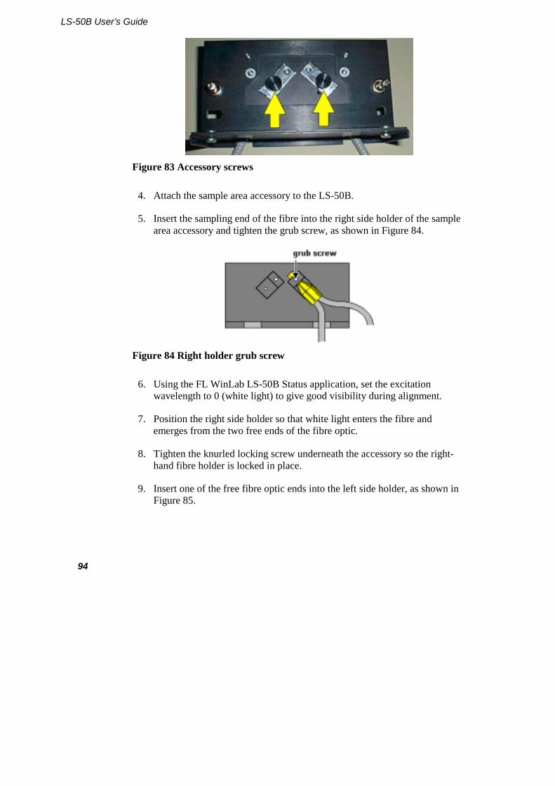
LS-50B User’s Guide
94
Figure 83 Accessory screws
4. Attach the sample area accessory to the LS-50B.
5. Insert the sampling end of the fibre into the right side holder of the sample area accessory and tighten the grub screw, as shown in Figure 84.
Figure 84 Right holder grub screw
6. Using the FL WinLab LS-50B Status application, set the excitation wavelength to 0 (white light) to give good visibility during alignment.
7. Position the right side holder so that white light enters the fibre and emerges from the two free ends of the fibre optic.
8. Tighten the knurled locking screw underneath the accessory so the right-hand fibre holder is locked in place.
9. Insert one of the free fibre optic ends into the left side holder, as shown in Figure 85.
Accessories: Installation and Use
95
Figure 85 Inserting into the left holder
10. Turn the fibre until it is vertical and tighten the grub screw, as shown in Figure 86.
Figure 86 Left holder grub screw
11. Open the central optical cover inside the LS-50B and observe the emission entrance slit through the open position of the emission filter wheel, as shown in Figure 87.
Figure 87 Viewing the emission slit
LS-50B User’s Guide
96
12. Move the left fibre holder until the light is central on the slit, as shown in Figure 88.
Figure 88 Aligning the light
13. Tighten the knurled screw under the left fibre holder, to lock it.
14. Remove the sampling fibre end from the right fibre holder.
15. Loosen the grub screw in the right fibre holder and insert the free fibre end, as shown in Figure 89.
Figure 89 Inserting the fibre end
16. Rotate the fibre until it is vertical then tighten the grub screw, as shown in Figure 90.
Accessories: Installation and Use
97
Figure 90 Right holder grub screw
17. Rotate the right fibre until the excitation light beam image is centralized on the optical fibres.
18. Loosen the grub screw again and move the fibre into and out of the holder (keeping the fibre bundle vertical) to optimize the focus.
19. Tighten the knurled screw under the base plate to lock the fibre.
20. Replace the LS-50B central optical cover.
21. Turn on the photomultiplier voltage.
22. Close the main cover.
Operation
The ~22o angle of emergence of light from the sampling end means that the further the sampling end is from the sample, the larger the excitation image will be, as shown in Figure 91.
Figure 91 Sampling positions
LS-50B User’s Guide
98
However, if the sampling end contacts the sample, very little light will be accepted by the emission fibre. Optimal sensitivity is achieved with a 1-2 mm distance between the fibre optic and the sample.
Improving resolution further can be achieved by masking the sampling end of the fibre to eliminate the outer parts of the semicircles from measurement:
Figure 92 Masking the outer areas
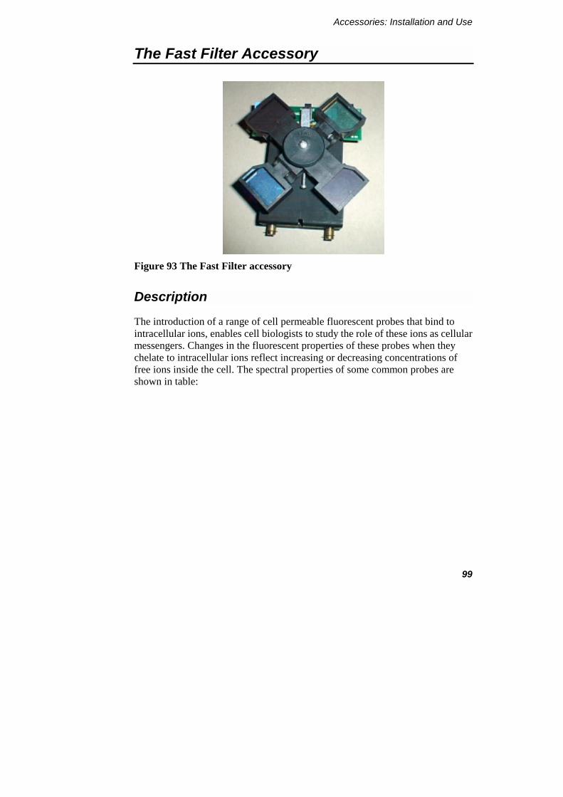
Accessories: Installation and Use
99
The Fast Filter Accessory
Figure 93 The Fast Filter accessory
Description
The introduction of a range of cell permeable fluorescent probes that bind to intracellular ions, enables cell biologists to study the role of these ions as cellular messengers. Changes in the fluorescent properties of these probes when they chelate to intracellular ions reflect increasing or decreasing concentrations of free ions inside the cell. The spectral properties of some common probes are shown in table:
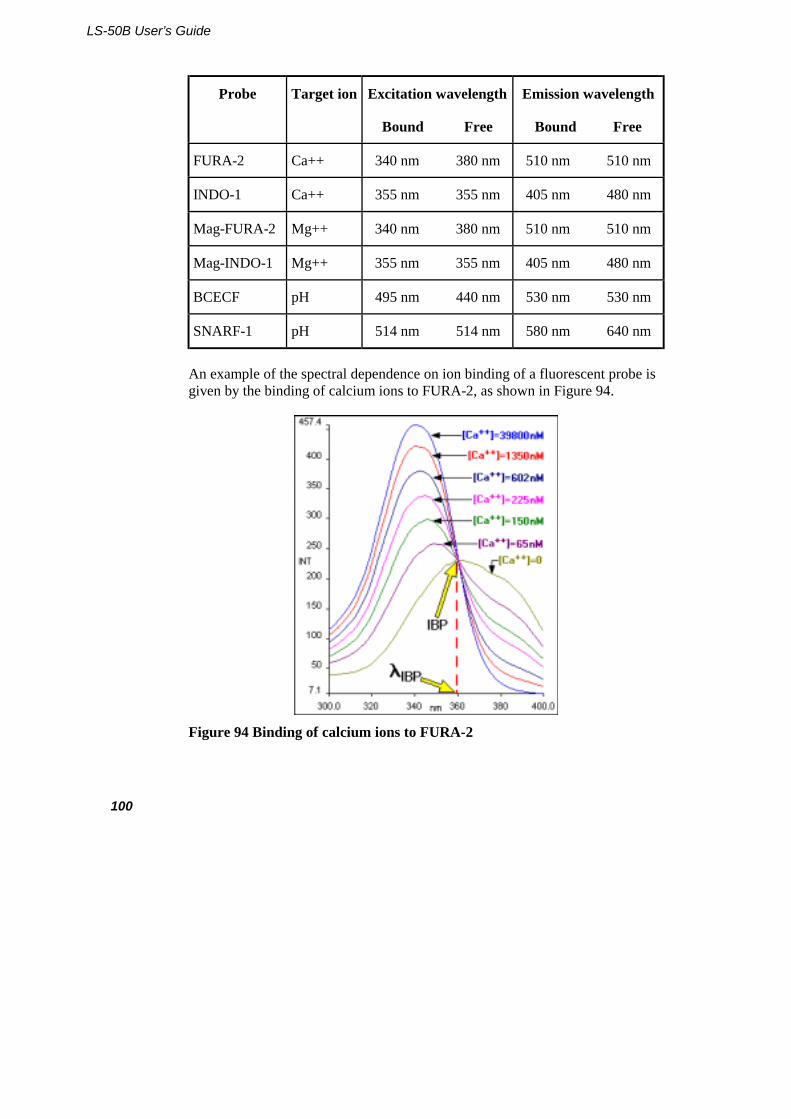
LS-50B User’s Guide
100
Probe Target ion Excitation wavelength
Bound Free
Emission wavelength
Bound Free
FURA-2 Ca++ 340 nm 380 nm 510 nm 510 nm
INDO-1 Ca++ 355 nm 355 nm 405 nm 480 nm
Mag-FURA-2 Mg++ 340 nm 380 nm 510 nm 510 nm
Mag-INDO-1 Mg++ 355 nm 355 nm 405 nm 480 nm
BCECF pH 495 nm 440 nm 530 nm 530 nm
SNARF-1 pH 514 nm 514 nm 580 nm 640 nm
An example of the spectral dependence on ion binding of a fluorescent probe is given by the binding of calcium ions to FURA-2, as shown in Figure 94.
Figure 94 Binding of calcium ions to FURA-2
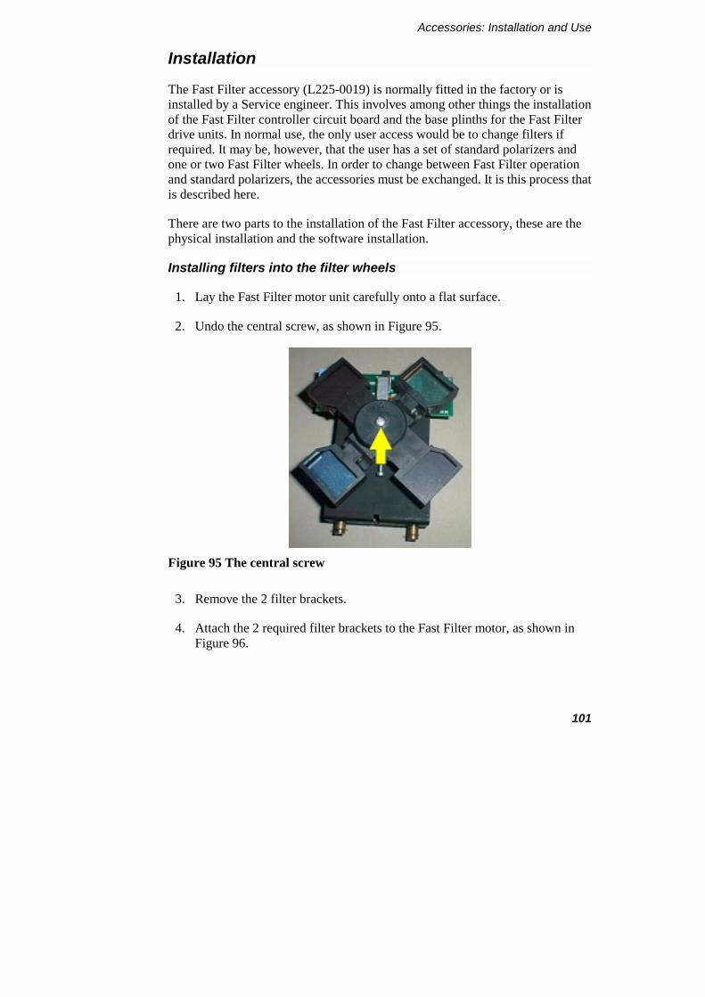
Accessories: Installation and Use
101
Installation
The Fast Filter accessory (L225-0019) is normally fitted in the factory or is installed by a Service engineer. This involves among other things the installation of the Fast Filter controller circuit board and the base plinths for the Fast Filter drive units. In normal use, the only user access would be to change filters if required. It may be, however, that the user has a set of standard polarizers and one or two Fast Filter wheels. In order to change between Fast Filter operation and standard polarizers, the accessories must be exchanged. It is this process that is described here.
There are two parts to the installation of the Fast Filter accessory, these are the physical installation and the software installation.
Installing filters into the filter wheels
1. Lay the Fast Filter motor unit carefully onto a flat surface.
2. Undo the central screw, as shown in Figure 95.
Figure 95 The central screw
3. Remove the 2 filter brackets.
4. Attach the 2 required filter brackets to the Fast Filter motor, as shown in Figure 96.
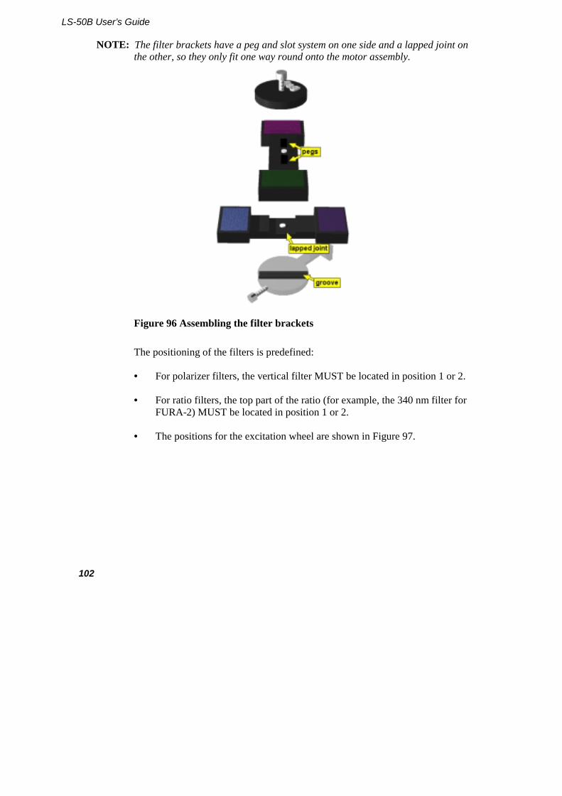
LS-50B User’s Guide
102
NOTE: The filter brackets have a peg and slot system on one side and a lapped joint on the other, so they only fit one way round onto the motor assembly.
Figure 96 Assembling the filter brackets
The positioning of the filters is predefined:
• For polarizer filters, the vertical filter MUST be located in position 1 or 2.
• For ratio filters, the top part of the ratio (for example, the 340 nm filter for FURA-2) MUST be located in position 1 or 2.
• The positions for the excitation wheel are shown in Figure 97.
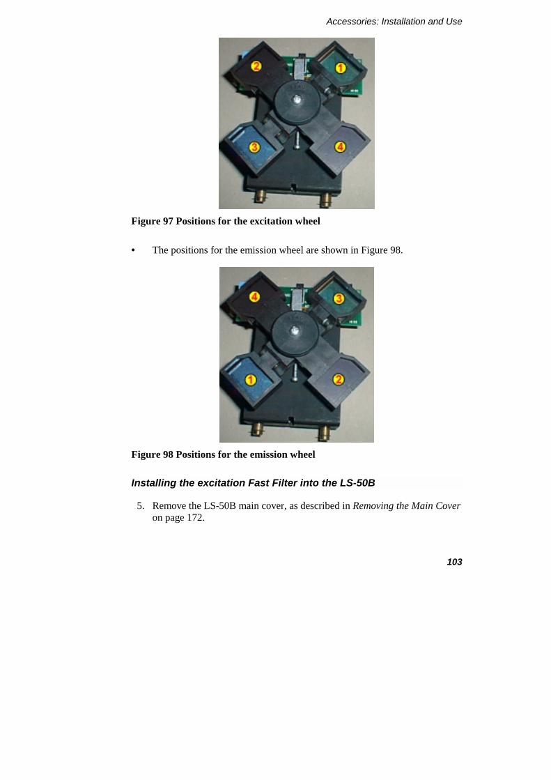
Accessories: Installation and Use
103
Figure 97 Positions for the excitation wheel
• The positions for the emission wheel are shown in Figure 98.
Figure 98 Positions for the emission wheel
Installing the excitation Fast Filter into the LS-50B
5. Remove the LS-50B main cover, as described in Removing the Main Cover on page 172.
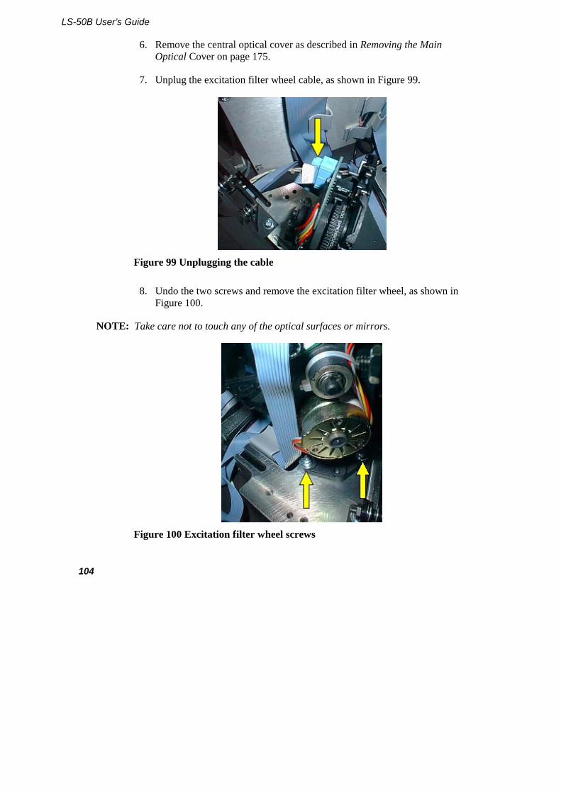
LS-50B User’s Guide
104
6. Remove the central optical cover as described in Removing the Main Optical Cover on page 175.
7. Unplug the excitation filter wheel cable, as shown in Figure 99.
Figure 99 Unplugging the cable
8. Undo the two screws and remove the excitation filter wheel, as shown in Figure 100.
NOTE: Take care not to touch any of the optical surfaces or mirrors.
Figure 100 Excitation filter wheel screws
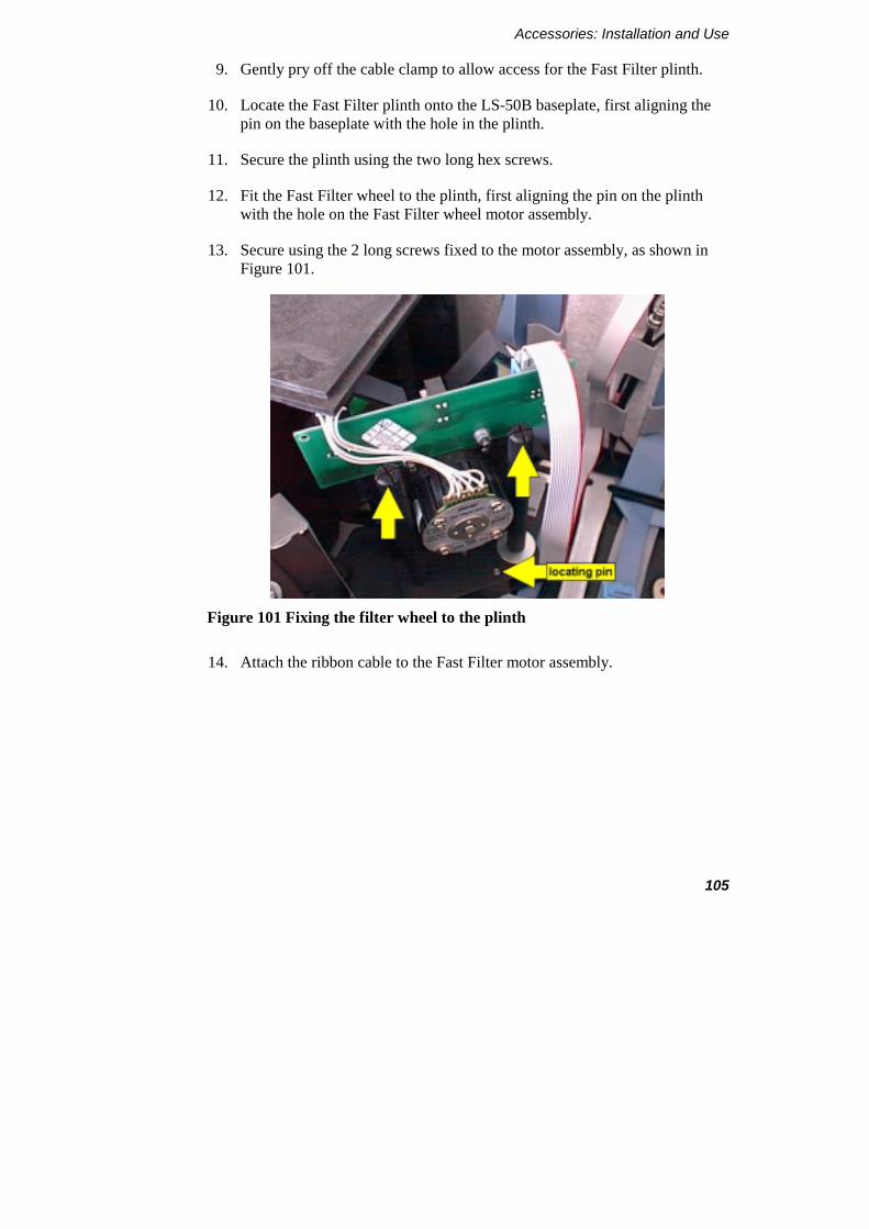
Accessories: Installation and Use
105
9. Gently pry off the cable clamp to allow access for the Fast Filter plinth.
10. Locate the Fast Filter plinth onto the LS-50B baseplate, first aligning the pin on the baseplate with the hole in the plinth.
11. Secure the plinth using the two long hex screws.
12. Fit the Fast Filter wheel to the plinth, first aligning the pin on the plinth with the hole on the Fast Filter wheel motor assembly.
13. Secure using the 2 long screws fixed to the motor assembly, as shown in Figure 101.
Figure 101 Fixing the filter wheel to the plinth
14. Attach the ribbon cable to the Fast Filter motor assembly.
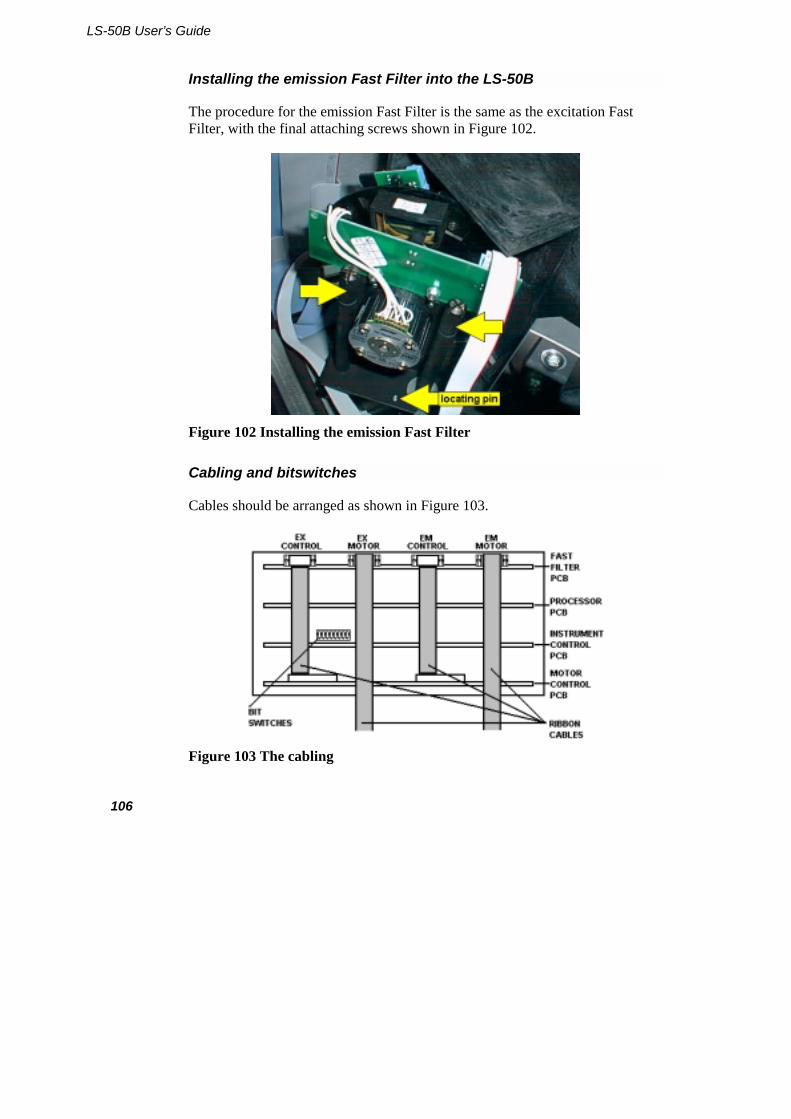
LS-50B User’s Guide
106
Installing the emission Fast Filter into the LS-50B
The procedure for the emission Fast Filter is the same as the excitation Fast Filter, with the final attaching screws shown in Figure 102.
Figure 102 Installing the emission Fast Filter
Cabling and bitswitches
Cables should be arranged as shown in Figure 103.
Figure 103 The cabling
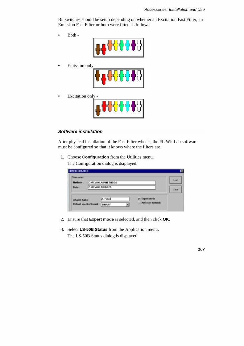
Accessories: Installation and Use
107
Bit switches should be setup depending on whether an Excitation Fast Filter, an Emission Fast Filter or both were fitted as follows:
• Both -
• Emission only -
• Excitation only -
Software installation
After physical installation of the Fast Filter wheels, the FL WinLab software must be configured so that it knows where the filters are.
1. Choose Configuration from the Utilities menu. The Configuration dialog is dsiplayed.
2. Ensure that Expert mode is selected, and then click OK.
3. Select LS-50B Status from the Application menu. The LS-50B Status dialog is displayed.
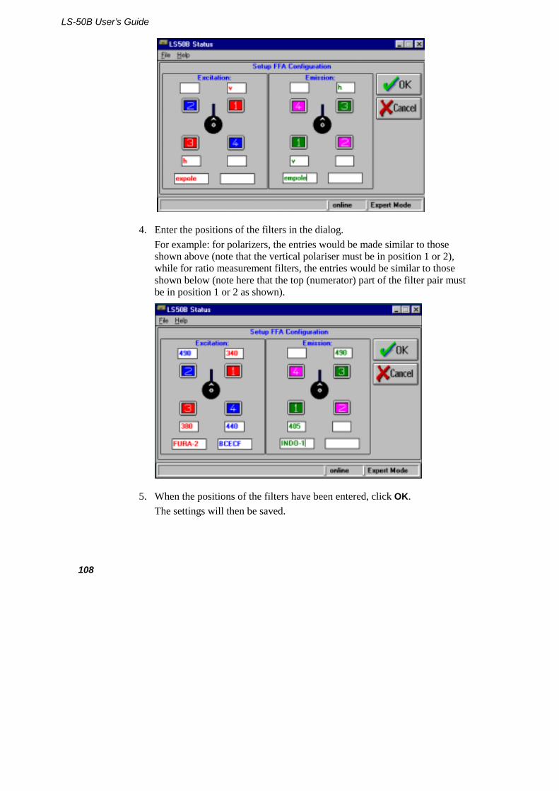
LS-50B User’s Guide
108
4. Enter the positions of the filters in the dialog. For example: for polarizers, the entries would be made similar to those shown above (note that the vertical polariser must be in position 1 or 2), while for ratio measurement filters, the entries would be similar to those shown below (note here that the top (numerator) part of the filter pair must be in position 1 or 2 as shown).
5. When the positions of the filters have been entered, click OK. The settings will then be saved.

Accessories: Installation and Use
109
Operation
Collection of data using the Fast Filter accessory is performed using the Fast Filter application in the FL WinLab menu.
On starting, the Fast Filter application interrogates the filter position information entered via the LS-50B Status application. If polarizers are present then options for time-dependent collection of polarization and anisotropy will be offered. If the filters are standard band-pass type, then ratiometric options are offered.
A description of the Fast Filter application is given in the FL WinLab Software manual.
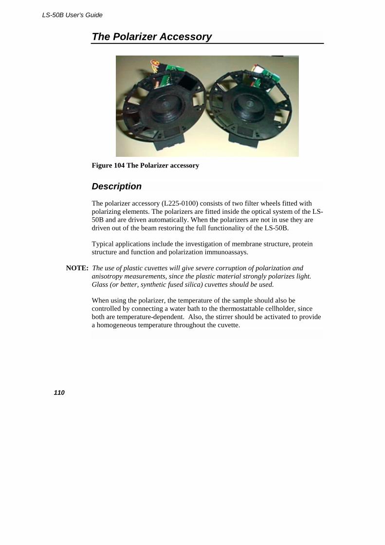
LS-50B User’s Guide
110
The Polarizer Accessory
Figure 104 The Polarizer accessory
Description
The polarizer accessory (L225-0100) consists of two filter wheels fitted with polarizing elements. The polarizers are fitted inside the optical system of the LS-50B and are driven automatically. When the polarizers are not in use they are driven out of the beam restoring the full functionality of the LS-50B.
Typical applications include the investigation of membrane structure, protein structure and function and polarization immunoassays.
NOTE: The use of plastic cuvettes will give severe corruption of polarization and anisotropy measurements, since the plastic material strongly polarizes light. Glass (or better, synthetic fused silica) cuvettes should be used.
When using the polarizer, the temperature of the sample should also be controlled by connecting a water bath to the thermostattable cellholder, since both are temperature-dependent. Also, the stirrer should be activated to provide a homogeneous temperature throughout the cuvette.

Accessories: Installation and Use
111
Installation
The polarizers are normally factory fitted or service installed. However, if you have one or two Fast Filter wheels fitted: if these do not have polarizers fitted, then to carry out polarization the Fast Filter wheels will have to be exchanged for the polarizers.
1. Remove the LS-50B main cover, as described in Removing the Main Cover on page 172.
2. Remove the central optical cover as described in Removing the Main Optical Cover on page 175.
3. Unplug the excitation filter wheel cable, as shown in Figure 105.
Figure 105 Excitation filter wheel cable
4. Undo the two screws and remove the excitation filter wheel, as shown in Figure 106.
NOTE: Take care not to touch any of the optical surfaces or mirrors.
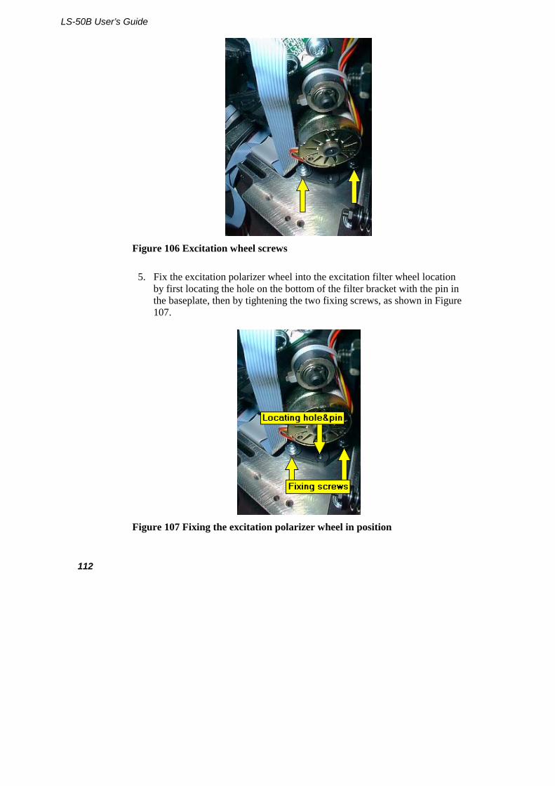
LS-50B User’s Guide
112
Figure 106 Excitation wheel screws
5. Fix the excitation polarizer wheel into the excitation filter wheel location by first locating the hole on the bottom of the filter bracket with the pin in the baseplate, then by tightening the two fixing screws, as shown in Figure 107.
Figure 107 Fixing the excitation polarizer wheel in position
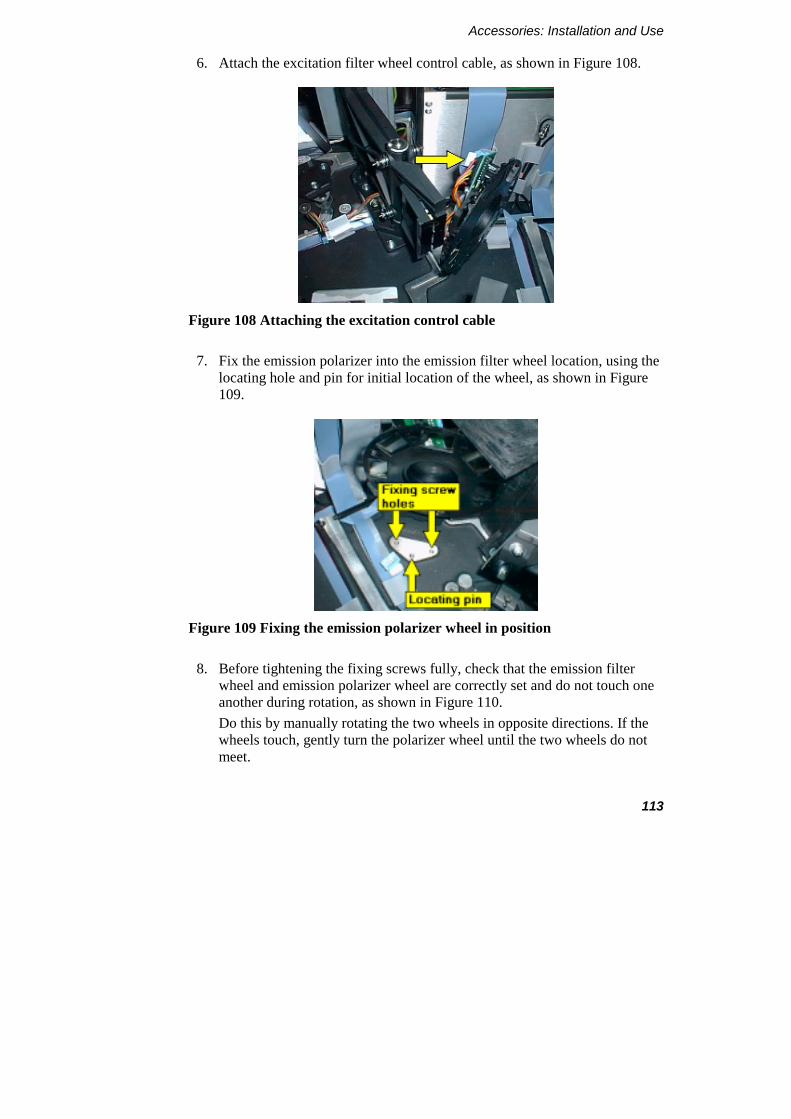
Accessories: Installation and Use
113
6. Attach the excitation filter wheel control cable, as shown in Figure 108.
Figure 108 Attaching the excitation control cable
7. Fix the emission polarizer into the emission filter wheel location, using the locating hole and pin for initial location of the wheel, as shown in Figure 109.
Figure 109 Fixing the emission polarizer wheel in position
8. Before tightening the fixing screws fully, check that the emission filter wheel and emission polarizer wheel are correctly set and do not touch one another during rotation, as shown in Figure 110. Do this by manually rotating the two wheels in opposite directions. If the wheels touch, gently turn the polarizer wheel until the two wheels do not meet.
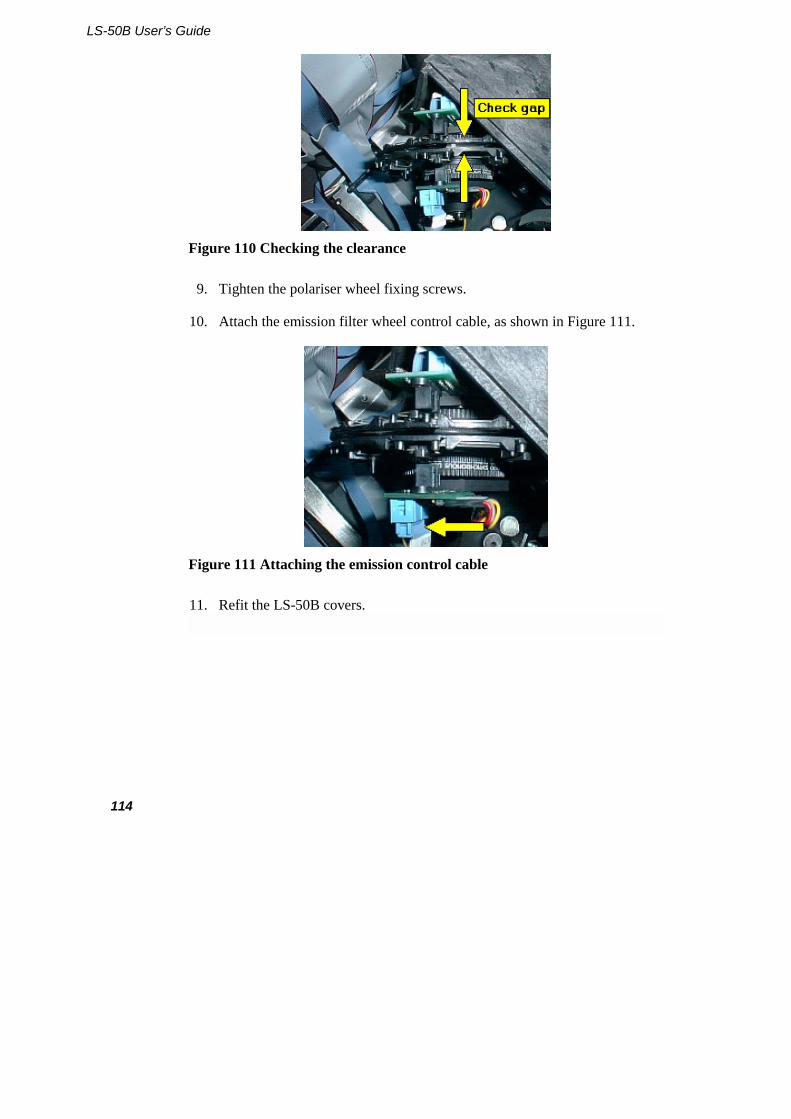
LS-50B User’s Guide
114
Figure 110 Checking the clearance
9. Tighten the polariser wheel fixing screws.
10. Attach the emission filter wheel control cable, as shown in Figure 111.
Figure 111 Attaching the emission control cable
11. Refit the LS-50B covers.

Accessories: Installation and Use
115
Operation
The measurement of polarization or anisotropy values can be performed using the FL WinLab software, where movement of the polarizers is done completely automatically.
1. In the FL WinLab software, select Read from the Applications menu.
2. Choose polarization or anisotropy. The polarisation/anisotropy value will be saved together with instrument parameters in the file specified in the Destination filename textbox. The format of the data file is as follows:
Mode: Polarisation Date: 16.07.98 09:57:34 Time Cuv ExSlit EmSlit ExWave EmWave Int Temp Ivv Ivh GF P Comment 0.0 1 10 10 350 455 1 30.0 123.5 97.6 0.93 0.153 DPH in DMPL 1:500 [surfactant]=1.3mM 1 10 10 350 455 1 30.0 123.5 85.2 0.93 0.218 DPH in DMPL 1:500 [surfactant]=0.65mM
LS-50B User’s Guide
116
Accessory spares
The following spares are available:
Accessory Description Part Number
Stirred cellchanger Stirrer bars (pack/6) 0497-8499
Thermostattable cellholders Tubing (2m) 0497-3213
Front Surface Powder holder complete with silica window
5212-3164
Front Surface Silica window for powder holder
5212-3814
Septum injector Silicone rubber septa (pack )
Any cuvette holder Semi-micro cuvette adapter
1cm Square-top cuvettes Coverslip accessory
Pulsed xenon source L225-1157
Red-sensitive photomultiplier
5212-4966
Plate reader Hi-white 96-well microplates (pack of 100)
L225-1692

RS232 Commands 5

RS232 Commands
119
Introduction
This section describes the instrument resident software in the Model LS-50B Luminescence Spectrometer.
All the instrument facilities described in this section are controlled via a single RS232C communications channel at 9600 baud. Data is output via the RS232C link and is also output in analogue form. The instrument has the following facilities:
• The SCAN BUSY logic output is asserted when the instrument is collecting data for output via the RS232 channel.
• Two general-purpose logic inputs are provided. One (EVENT) is used to mark output data with timed events; the other (START) is used by external devices to prompt data collection.
NOTE: In older instruments, the EVENT output is labeled 'Remote Start' and the START input is labeled 'Remote Integrate".
• Both monochromators may be driven to any valid wavelength (200-800 nm for excitation and 200-900 nm for emission). They may be scanned either individually or synchronously. When synchronously scanning either a constant wavelength separation or a constant frequency separation can be selected. All these operations can be aborted.
• The source is automatically turned off 30 minutes after the last external control command is received if data collection is not active.
• Data collection may be set up to operate in fluorescence, phosphorescence or bio-/chemi-luminescence modes. Data may be collected while the monochromators are stationary or scanning. In phosphorescence, bio or chemi-luminescence modes the main emission gate and delay times are fully adjustable in steps of 10 microseconds. Control is also available over the number of flashes and length of a data collection cycle. In bioluminescence mode the source is turned off and ratioing disabled.
LS-50B User’s Guide
120
• Collected data is excitation corrected, block averaged, ratioed, normalized, and smoothed. Excitation correction is achieved by reference to a table of correction factors held in non-volatile memory. Smoothing filters are 'Savitsky-Golay' or binomial types with filter widths user selectable as any odd number between 3 and 101 points. Normalization is by linear interpolation between nearest points to return data at specified abscissa interval.
• Data output is via RS232 and analogue output. Data may be output from anywhere on the data processing chain with the restriction that only one data value per mains cycle may be Output. Data to the analogue output may be scaled.
• Facilities are included to generate the excitation correction tables.
• Both slits are independently driveable. Automatic facilities are available for calibration. Calibration data is held in non-volatile memory. Preset photomultiplier (PMT) voltages are set up as a function of excitation slit setting.
• The emission filter wheel may be driven to any position independent of other instrument conditions. The excitation filter is selected automatically according to the current excitation monochromator position, unless a polarizer or blank position has been selected. A manual override to the automatic excitation filter selection is provided. A separate emission polarizer wheel accessory is provided.
• If fitted, a total emission accessory (emission mirror) can be driven in or out of the beam.
• A timed-event marker accessory fitted with temperature sensor and stirrer is supported.
• An x-y table may be used as a well plate multisampler or as a TLC plate reader. When used as a TLC plate reader, the probe may be scanned at constant speed parallel to a selected axis.
• A magnetic stirrer is available as an accessory and may be set to one of two possible speeds.
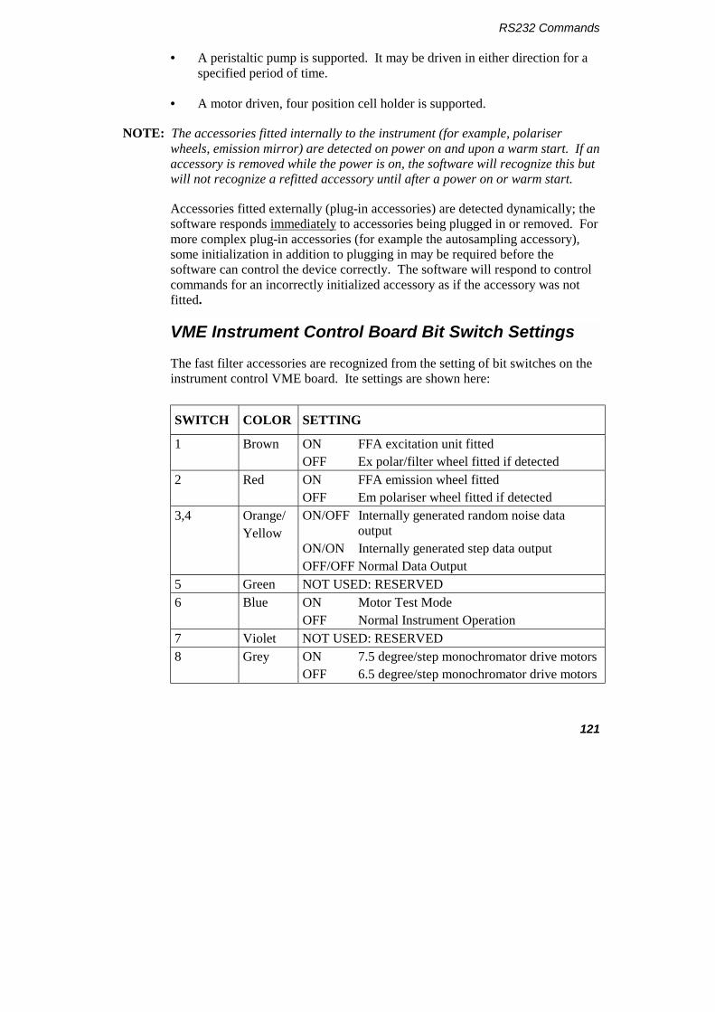
RS232 Commands
121
• A peristaltic pump is supported. It may be driven in either direction for a specified period of time.
• A motor driven, four position cell holder is supported.
NOTE: The accessories fitted internally to the instrument (for example, polariser wheels, emission mirror) are detected on power on and upon a warm start. If an accessory is removed while the power is on, the software will recognize this but will not recognize a refitted accessory until after a power on or warm start.
Accessories fitted externally (plug-in accessories) are detected dynamically; the software responds immediately to accessories being plugged in or removed. For more complex plug-in accessories (for example the autosampling accessory), some initialization in addition to plugging in may be required before the software can control the device correctly. The software will respond to control commands for an incorrectly initialized accessory as if the accessory was not fitted.
VME Instrument Control Board Bit Switch Settings
The fast filter accessories are recognized from the setting of bit switches on the instrument control VME board. Ite settings are shown here:
SWITCH COLOR SETTING
1 Brown ON FFA excitation unit fitted OFF Ex polar/filter wheel fitted if detected
2 Red ON FFA emission wheel fitted OFF Em polariser wheel fitted if detected
3,4 Orange/ Yellow
ON/OFF Internally generated random noise data output
ON/ON Internally generated step data output OFF/OFF Normal Data Output
5 Green NOT USED: RESERVED 6 Blue ON Motor Test Mode
OFF Normal Instrument Operation 7 Violet NOT USED: RESERVED 8 Grey ON 7.5 degree/step monochromator drive motors
OFF 6.5 degree/step monochromator drive motors
LS-50B User’s Guide
122
Section 1- RS232C Communications
All facilities are controllable via the RS232C link. Data transmission is fixed at 9600 baud, 8 bits, no parity and 1 stop bit. The instrument is always ready to receive data. All data sent from the instrument is in response to a command sent to it. The instrument outputs a busy error code if it is executing a command and another command is received. An exception to this rule occurs when interpreting an abortable command and the command received is abort. In such cases an error code is not output in response to the abort command - the error code sent in response to the original command will indicate that the command was aborted. The second exception is when a calibration command is active and a continue command is expected.
The RS232C interface may operate in either free-running or prompted modes. In free-running mode output can be stopped/restarted by conventional DC1/DC3 protocol. DC3 pauses transmission at the end of the current record being transmitted. The interface, defaults to prompted mode on power up.
The 25-way connector on the instrument is configured as DCE:
pin 1 chassis ground pin 6 DSR pin 2 data from instrument pin 7 signal ground pin 3 data to instrument pin 8 RCD pin 4 RTS pin 20 DTR pin 5 CTS
No connections are made to the other pins.
Data sent to the instrument is either a command or special character.
Command syntax is as follows:
$<mnemonic> <parameter list><terminator>
Where:
• The mnemonic is always 2 alpha characters. (Refer to Section 2 - Command Formats on page 128 for valid mnemonics.)
• The parameter list is a series of parameters delimited by a comma (,). A parameter is a series of ASCII characters representing integer, real, or string.
RS232 Commands
123
• The terminator is a single character: either c/r or l/f.
A command string, including the terminator, may not be longer than 128 characters.
Special characters are as follows:
• BS or % characters may be used to delete the previous character in a command string.
• NULL and DEL are ignored.
• DC1 prompts output when in prompted mode or causes return to free-running mode in the case that prompted mode was entered by receipt of DC3. Up to 32767 prompts may be accumulated. DC1 is ignored in free running mode.
• DC3 causes entry to prompted mode if in free-running mode, otherwise it is ignored.
Data is output in the form of records of up to 126 ASCII characters terminated with c/r and l/f or as a fixed length record of 40 bytes in the case of binary data transmission. The first response to any command is an output record consisting of a 4 digit error code. On some commands other output records may follow. The last transmission in response to a command is an error code output record. Any output records that do not contain only an error code have a DEL character in the first position.
In some cases the user may start an operation which requires some interaction with the user (for example, calibration procedures). In such cases unique error codes may be returned indicating to the user that either text or spectral data records are to follow. Another unique code indicates that no more data will be sent in response to this command but that the operation started is still active and is awaiting instruction in the form of one of the dialogue commands (for example, Continue). Only when the operation has finished will one of the normal error codes be sent indicating success or failure of the whole operation.

LS-50B User’s Guide
124
Monochromator Drive
The monochromators may be driven in one of two modes:
In Scan mode, either or both monochromators may be driven between specified limits. If both monochromators are driven, the excitation monochromator is driven at the specified constant wavelength speed and the emission monochromator either a constant wavelength or constant frequency offset from the excitation monochromator. If a single monochromator is driven, then it is at the specified wavelength speed.
The Scan start is synchronized to a mains cycle. Velocity may be 10 to 1500 nm/min or -10 to -1500 nm/min. Limits are specified for each monochromator and must in the range 200 to 800 nm for excitation, and 200 to 900 nm for emission. Wavelengths are a multiple of 0.1 nm. Scanning is in the direction specified by the sign of the scan velocity. A scan ends when one of the monochromators encounters its end limit or on an abort request.
In GOTO mode either monochromator is driven as fast as possible in the specified direction. Destination wavelengths must either be 0 nm or within the scan limits above. Unless an excitation polariser or blank position has been selected or a fast filter excitation unit is fitted, the excitation filter is selected according to the excitation monochromator destination. For excitation wavelengths <410 nm, a clear (no filter) position is selected, otherwise a 350 nm cutoff filter is used. A GOTO ends when the monochromator and excitation filter is at its destination, or when abort is requested.
Plate Reader Driver
The plate reader may be used as a well plate reader or as a TLC plate reader. In TLC plate reader mode the motors may be moved either in Scan or GOTO modes but in well plate mode only GOTO mode is available.
Positions are specified in units of 0.1 nm in the TLC plate reader case and as sample positions (1-96) in the well plate case.
In Scan mode the limits are 0 to 99.0 mm for the x-axis and 0 to 63.0 nm for the y-axis. The scan is in the direction specified by the sign of the speed.
RS232 Commands
125
Source Control and Photomultiplier Control
Thirty minutes after the last user command has been completed, the source is turned off but the idle time drive continues.
The PMT voltage is set nominally to a voltage dependent on the excitation slit position and the position of the excitation monochromator.
A PMT overload detection mechanism operates to indicate conditions where the ordinate data may be distorted by saturation effects. An error is indicated if the protection mechanism becomes active during a period of data collection but data collection continues.
Slit and Filter Motors
All motors listed here may only be driven when a scan or time drive is not active.
Excitation and emission slits are provided as standard and each may be independently driven in the range 0 and 2.5 to 15 nm (excitation), 0 and 2.5 to 20 nm (emission) to positions that are multiples of 0.1 nm.
NOTE: Slit settings below 2.5 nm are not calibrated.
An emission mirror is provided as an option. When the mirror is moved into place the emission monochromator is driven to 800 nm and emission wavelength subsequently assumed to be 0.
An emission filter with 8 positions is provided. The positions are: cut-off filter 1 to 5; blank; 1% attenuator and no filter.
An excitation cutoff filter at 390 nm is provided. This is switched in to the beam at 410 nm to remove second order artifacts.
An emission polarizer is provided as an accessory with the following positions: horizontal polarizing filter; vertical polarizing filter; and no filter.
An excitation polarizer is provided as an accessory with the following positions: horizontal polarizing filter, vertical polarizing filter, blank, and no filter.
LS-50B User’s Guide
126
A conceptual excitation shutter is provided in the form of an independent source ON/OFF switch.
Analogue Output
Analogue outputs of 0 - 10 V and 0 - 1 V are provided with a resolution of one part in 1024. The data output is processed in the same way as that output via the RS232C channel. The data is multiplied by a user specified scaling factor and then a user specified offset is added before output.
Sample Acquisition Accessories
There are 4 types of sample acquisition accessory available: the peristaltic pump, the four-position cellchanger, the plate reader and the biokinetic accessory.
• The peristaltic pump may be driven in either direction for a period of time specified in units of 0.1 seconds. Pumping may be aborted at any time by the user.
• The four-position cellchanger may be driven to position. The cellchanger may be fitted with coils driving magnetic stirrer bars. The stirrer speed may be set to one of three values: off; low; high.
• The plate reader can be used to read samples from a well plate, a TLC plate or a gel. For a well plate, the plate reader takes a reading at each well. For a TLC plate or gel, the plate is scanned in the x or y direction, starting at specified co-ordinates.
• The biokinetic accessory enables the temperature of the cell to be measured. It also has a stirrer as in the four-position cell holder (above) and the facility for event marking.
The Sipper, cell holder, and plate reader accessories require initialization before they are used. Initialization is required each time they are plugged into the instrument or if any operation is performed that changes the motor position(s) other than under control of the instrument. Explicit initialization commands are available. The instrument software automatically initializes accessories if a command to move a fitted accessory is issued and the accessory has not been initialized since it was last plugged in. An error is reported from accessory control commands if the accessory becomes unplugged at any time before or during the command or if the software initialization is unsuccessful.
RS232 Commands
127
Fast Filter Accessory (FFA)
Fast rotating filter units for excitation and emission can be fitted in place of the excitation filter/polarizer wheel and emission polarizer wheel. The FFA units are synchronized with the source flash and fluorescence data collection cycle. Data points are collected and output for each filter position at a rate controlled by the $FI command. The maximum data output rate is one point or filter position per fluorescence data collection cycle (mains cycle). Data collection is not possible in modes other than fluorescence.
The FFA units are controlled by a separate microprocessor board fitted with the existing VME boards. When FFA units are signaled fitted by the bit switch settings detailed on page 107, control signals are passed between the CPU and FFA control board via the ports usually used for the excitation filter/polarizer wheel and emission polarizer wheel accessory. If the bit switches are not set correctly inappropriate signals will be sent by the CPU and the accessories will not function.
During FFA data collection, synchronization pulses from the FFA board are monitored by the CPU software. Pulses must occur exactly once per filter unit rotation, be at least 1.7 ms in duration, and start in a window between 7.0 and 11.0 ms after the source flash (50 Hz and 60 Hz operation). If these conditions are not observed, data collection is terminated immediately and an error reported via the RS232C data output.
LS-50B User’s Guide
128
Section 2 - Command Formats
Following is a list of error codes.
0000 No error.
CODES INDICATING END OF COMMAND EXECUTION
0002 Command not recognized.
0003 Invalid parameter format (real where integer expected).
0005 Not enough parameters.
0006 Illegal character in expected numeric parameter.
0008 Negative numeric where positive expected.
0009 Value out of range.
0014 Input buffer overflow.
0022 Parity, framing, or overrun error.
0099 Abort termination of command.
0100 Accessory not fitted.
0103 Invalid phosphorescence data collection parameters.
0104 Calibration peak not found.
0105 Calibration operation not successful - user message gives reason.
0106 Non-volatile memory error - fatal.
0107 PMT over range warning.
0108 Non-volatile memory error - recovered from backup copies.
0109 Too many parameters.
RS232 Commands
129
0110 Instrument busy.
0111 Invalid parameter for instrument in current state.
0112 Motor stepping error or Fast Filter Accessory missing synchronous pulse.
0113 Scan finished prematurely but not due to abort command (for example excess speed in constant frequency scan).
0114 Scan recoverable error (data integrity cannot be guaranteed).
0200 to Auto-calibration operation internal errors. (User text messages 0215 give details).
CODES NOT INDICATING END OF COMMAND EXECUTION
1000 Last text string before end of current step of operation
1001 Text records to follow.
1002 Spectral data records to follow.
The following sections list commands, their associated parameters and output.
Unless otherwise stated all commands that have associated parameters will return the current value of the parameter(s) if the command is sent with no parameters and there is no error. The format of the response is: 0000c/r l/f <parameter values>c/r l/f 0000c/r l/f
Parameter values will be an ASCII representation of the value of the same type as the parameter specified for input. Multiple parameters are separated by commas. Asterisks are used to denote parameter values outside permitted ranges.

LS-50B User’s Guide
130
Monochromator Scan Control Commands
Command: ABSCISSA HIGH LIMIT
Syntax: $AH <abscissa limit>
Description: Sets either a new emission or excitation high abscissa limit depending on monochromator selection. Emission limit must be in range 200.0 to 900.0. Excitation limit must be in range 200.0 to 800.0. Limits are rounded to nearest 0.1 and are in units of wn. A high limit must be greater than the corresponding low limit. Power-on defaults for high limits are: 800 for excitation and 900 for emission. Returns high limit for selected monochromator if no parameter is specified.
NOTE: Excitation limit is set if monochromator selection is 'both'. Refer to command $MX.
Command: ABSCISSA LOW LIMIT
Syntax: $AL <abscissa limit>
Description: As for high limit. Power-on defaults for low limits are 200 for both. Returns low limit for selected monochromator if parameter is not specified.
Command: MONOCHROMATOR SELECTION QUALIFICATION
Syntax: $MQ qualifier
Description: Causes subsequent scans of both monochromators to be 'constant wavelength' if qualifier = 0, or 'constant frequency' if qualifier =1. Qualifier must be integer. Power-on default is 0.
RS232 Commands
131
Command: MONOCHROMATOR SELECTION
Syntax: $MX code
Description: Sets specified monochromator selection for subsequent scans: Code = 0 Excitation only, 1 Emission only, 2 Both. Returns error 0111 if emission or both selected with emission mirror in. Power-on default is 0.
Command: SCAN
Syntax: $SC start type
Description: Starts a scan according to start type (1 = immediate; 2=after START event detected). If the first error code indicated no error then a scan status record is sent. The monochromators are driven to the start positions specified by $AL, $AH, $SS and $MX commands.
Data records are then sent as data become available. An error code is sent on completion of the scan. A data record consists of 10 successive output points. A last record is padded with representations of the value -9999 and contains at least one of these. A data record is transmitted either in ASCII or binary. In ASCII mode points are separated with commas. In binary mode a 4 byte representation is sent with the least significant bytes foremost. Each real output value is an integer in the range -5000 to +999999 ('+' sign suppressed) and is derived from the data available in the data processing chain multiplied by the scale factor and truncated to integer. A data point appended with an exclamation mark (!) indicates that an event was detected during its collection.
A scan status record consists of the following:
50.<rev>,<ms><mq><dc><fi>,<ex.wavelength>, <em.slit width>, <max.points>,<data.int>.
LS-50B User’s Guide
132
Fields within the record separated by commas are of fixed length and are left-filled with spaces. Parameters in angle brackets are substituted as follows (x = ASCH digit, space, or minus):
<rev> is 2 character integer representing software revision. The first character corresponds to the software release number.
<ms> is a single character integer code representing current monochromator selection (see $MX command).
<mq> is a single character integer code representing current monochromator selection qualifier (see $MQ command).
<dc> is a single character integer code representing current data collection mode (see $PH command).
<fl> is a single character integer code representing current filter type (see $FL command).
<ex.wavelength> is fixed format (xxx.x) representing the excitation monochromator position at the start of the scan in nm.
<em.wavelength> is fixed format (xxx.x) representing the emission monochromator position at the start of the scan in rim.
<speed> is a 4 digit integer representing speed in nm/min. A leading minus is given for negative speeds.
<response> is a 3 digit integer representing current filter response number.
<ex. slit width> is fixed format (xx.x) representing the excitation slit width in nm.
<em. slit width> is fixed format (xx.x) representing the emission slit width in nm.
<max.points> is a 5 digit integer representing the maximum number of real data points that may be returned in the scan.
<data.int> is fixed format (xxxx.x) representing the abscissa interval between points in nm.
RS232 Commands
133
Command: SCAN DATA INTERVAL
Syntax: $SI interval
Description: Sets data output interval for subsequent scans. Interval is in range 0.1 to 5 nm and is rounded to nearest multiple of 0.1 nm. Current interval is returned if no parameter specified. Power-on default is 0.5 nm.
Command: SCAN SPEED
Syntax: $SS speed
Description: Sets the speed for subsequent scans. Speed may be integer in range 10 to 1500 or -1500 to -10 and has units of nm/min. Power-on default is 480. Returns scan speed if no parameter specified.
Time Drive Commands
Command: TIME DRIVE
Syntax: $TD points
Description: Causes a time drive returning the specified number of points. Points is an integer in the range 1 to 99999. An error code is returned immediately. If no error is indicated a time drive status record is sent followed by data records as the data become available. Data records are as per SCAN command. An error code is returned on completion. Returns error 0005 if no parameter specified.
A time drive status record consists of the following:
50.<rev>,<ms><mq><dc><fi>,<ex.wavelength>, <em.wavelength>,<speed>.<response>, <ex.slitwidth>,<em.slitwidth>,<max.points>, <data.int> c/r l/f 0000 c/r l/f
LS-50B User’s Guide
134
Fields within the record separated by commas are of fixed length and are left-filled with spaces. Parameters in angle brackets are substituted as follows (x = ASCH digit, space, or minus):
<rev> is two character code representing software revision.
<ms> is a single character integer code representing current monochromator selection (see $MX command).
<mq> is a single character integer code representing current monochromator selection qualifier (see $MO command).
<dc> is a single character integer code representing current data collection mode (see $PH command).
<fl> is a single character integer code representing current filter type (see $FL command).
<ex.wavelength> is fixed format (xxx.x) representing the excitation monochromator position in nm.
<em.wavelength> is fixed format (xxx.x) representing the emission monochromator position in nn.
<speed> is a 4 digit integer representing current scan speed in nm/min. A leading minus is given for negative speeds.
<response> is a 3 digit integer representing current response time (units 0.01s) (Refer to $RT).
<ex.slitwidth> is fixed format (xx.x) representing the excitation slit width in nm.
<em.slitwidth> is fixed format (xx.x) representing the emission slit width in nm.
<max.points> is a 5 digit integer representing the maximum number of real data points that may be returned in the time drive.
<data.int> is fixed format (xx.xx) representing the abscissa interval between points in seconds.
RS232 Commands
135
Command: RESPONSE TIME
Syntax $RT time
Description Set the time drive response time to the specified value (0 to 9.99 s, rounded down to nearest 0.02 s). Positive values turn filter and block average priming off; hence a propagation delay equal to the response time will occur before the first data point is ready for output. Negative values cause the filters to be fully primed with the first point; hence the propagation delay is zero but noise artifacts may distort initial data points output up to the response time.
A value of zero sets minimum response time consistent with the time interval and allows manual control of filter width. Power-on default is 0.
Returns current response time if no parameter is specified.
Command: TIME INTERVAL
Syntax: $TI time
Description: Sets the time drive time interval. Time must be in range 0.02 to 99.98 and is rounded to 0.02. Units are seconds. Power-on default is 0.5 s.
Command: PHOSPHORESCENCE DECAY TIME DRIVE
Syntax: $DP points
Description: Turns the source off and immediately starts a time drive with specified number of points output. Syntax and output format exactly as for $TD command. One data collection cycle will elapse between the source going off and the start of data collection. Raw data are smoothed according to current $RT setting.
LS-50B User’s Guide
136
Command: REMOTE TRIGGERED TIMEDRIVE
Syntax: $DS points
Description: Starts timedrive when START signal is detected. Specified number of points output. Syntax and output format exactly as for $TD command. Raw data are block averaged according to current $RT setting. $AB aborts command before or after remote signal is detected.
Command: REMOTE TRIGGERED PHOSPHORESCENCE DECAY TIMEDRIVE
Syntax: $PR POINTS
Description: Starts phosphorescence decay timedrive when START signal is detected. Specified number of points output. Syntax and output format exactly as for $DP command. Raw data are block averaged according to current $RT setting. $AB aborts command before or after remote signal is detected.
TLC Scan Commands
Command: TLC DATA INTERVAL
Syntax: $IT interval
Description: Sets data output interval for subsequent TLC scans. Interval is in range 0.1 to 2 mm and is rounded to nearest multiple of 0.1 mm. Power-on default is 0.5 mm.

RS232 Commands
137
Command: TLC X AXIS-HGH LIMIT
Syntax: $XH limit
Description: Sets high limit for TLC x scan. Range 0.1 to 99.0 mm. High limit may not be lower than TLC x low limit. Power-on default is 63.0 mm.
Command: TLC X AXIS LOW LIMIT
Syntax: $XL limit
Description: Sets low limit for TLC x scan. Range 0 to 98.9 mm. Low limit may not be higher than TLC x high limit. Power-on default is 0 mm.
Command: TLC Y AXIS HIGH
Syntax: $YH limit
Description: Set high limit for TLC y scan. Range 0.1 to 63.0 mm. High limit may not be lower than TLC y low limit. Power-on default is 63.0 mm.
Command: TLC Y AMS LOW
Syntax: $YL limit
Description: Set low limit for TLC y scan. Range 0 to 62.9 mm. Low limit may not be higher than TLC y high limit. Power-on default is 0 mm.

LS-50B User’s Guide
138
Command: TLC SCAN SPEED
Syntax: $TS speed
Description: Sets speed for subsequent TLC scans. Speed is integer in range -600 to 600 mm/min. Power-on default is 300 mm/min.
Command: TLC X SCAN
Syntax: $TX
Description: Starts TLC x scan. An error code is returned immediately. If no error is indicated a TLC scan status record is sent followed by data records as the data becomes available. Data records are as per Scan command. An error code is returned on completion.
A TLC scan status record consists of the following:
50.<rev>,<ms><mq><dc><fl>,<ex.wavelength>, <em.wavelength>,<speed>,<response>,<ex.slitwidth>, <em.slitwidth>,<max.points>,<data.int> c/f l/f 0000 c/r l/f
Fields within the record separated by commas are of fixed length and are left-filled with spaces. Parameters in angle brackets are substituted as follows (x = ASCII digit, space, or minus):
<rev> is two character code representing software revision.
<ms> is a single character integer code representing current monochromator selection (see $MX command).
<mq> is a single character integer code representing current monochromator selection qualifier (see $MQ command).
<dc> is a single character integer code representing current data collection mode (see $PH command).
<fl> is a single character integer code representing current filter type (see $FL command).
RS232 Commands
139
<ex.wavelength> is fixed format (xxx.x) representing the excitation monochromator position in nm.
<em.wavelength> is fixed format (xxx.x) representing the emission monochromator position in nm.
<speed> is a 4 digit integer representing speed in mm/min. A leading minus is given for negative speeds.
<response> is a 3 digit integer representing smoothing filter response width (000 to 101).
<ex.slitwidth> is fixed format (xx.x) representing the excitation slit width in nm.
<em.slitwidth> is fixed format (xx.x) representing the emission slit width in nm.
<max.points> is a 5 digit integer representing the maximum number of real data points that may be returned in the scan.
<data.int> is fixed format (xxxx.x) representing the abscissa interval between points in mm.
Command: TLC Y SCAN
Syntax: $TY
Description: Starts TLC y scan. See TLC X SCAN command for further information.
LS-50B User’s Guide
140
Data Collection/Processing Set Up Commands
Command: EXCITATION CORRECTION SELECTION
Syntax: $CX code
Description: Selects the excitation correction to be applied. Code is integer with following values: 0 no correction, 1 correction. Power-on default is 1.
NOTE: Scan and time drive commands return error code 0111 if no valid correction data in non-volatile memory and the code is 1.
Command: PHOSPHORESCENCE DARK CURRENT SELECT
Syntax: $DC code
Description: Selects whether a dark current of zero or one generated by the SET DARK CURRENT command is used. Code is 0 for dark current = 0, 1 otherwise. Power-on default is 0.
Dark current value is subtracted from the emission main signal on-the-fly before block averaging and ratioing (see $OS command).
Returns current dark current value if no parameter is specified.
Command: FILTER SELECT
Syntax: $FL code
Description: Selects the filtering applied in the data processing. Code is integer with one of following values: 0 Savitsky-Golay filter, 1 Binomial filter. Power-on default is 0.
RS232 Commands
141
Command: FILTER RESPONSE
Syntax: $FR response number
Description: Sets the active data processing filter characteristics for subsequent data processing. Response number must be an odd integer in range 3 to 101. Power-on default is response 19. Returns response of currently active filter if no parameter is specified.
Command: PHOSPHORESCENCE CYCLE
Syntax: $PC time
Description: Sets phosphorescence mode cycle time. Time is an integer in the range 0 to 9999 and has units of ms. If a time of zero is specified then the cycle time will be set to the minimum value required given current data collection parameters.
Returns error 0103 if time specified cannot be accommodated with current phosphorescence data collection parameters. Power-on default is to set minimum cycle time.
Command: PHOSPHORESCENCE DELAY
Syntax: $PD time
Description: Sets specified phosphorescence delay time for any subsequent phosphorescence mode data collection. Time is an integer in range 0 to 900 000 and has units of 0.01 ms. Error 0103 is returned if the time requested is greater than can be accommodated with current phosphorescence data collection parameters. Power-on default is 100 (1 ms).
LS-50B User’s Guide
142
Command: PHOSPHORESCENCE FLASH COUNT
Syntax: $PF count
Description: Sets the number of flashes per phosphorescence data collection cycle. Count is integer in range 1 to 10. Returns error 0103 if flash count requested cannot be accommodated with current phosphorescence data collection parameters. Power-on default is 1.
Command: PHOSPHORESCENCE GATE
Syntax: $PG time
Description: Sets specified phosphorescence gate time. Time is an integer in the range 1 ms to 50 000 ms. It can be incremented in steps of 0.01 ms. Returns error 0103 if requested time cannot be accommodated with current phosphorescence data collection parameters. Power-on default is 100 (l ms).
Command: PHOSPHORESCENCE/ FLUORESCENCE MODE
Syntax: $PH mode
Description: Mode is an integer with values: 0 sets normal fluorescence mode, 1 sets phosphorescence mode, 2 sets bioluminescence mode. Power-on default is 0. The current selection is returned if no parameter is specified.
RS232 Commands
143
Command: READ SINGLE DATA VALUE
Syntax: $RD time
Description: Performs a read operation averaging data for the time specified. Time is in range 0.1 to 100.0 seconds. If successful a no error response is sent immediately, then a single point data record followed by a final error code. Single point data record format:
<DEL><ex.wavelength>,<em.wavelength>,<temp>, <intensity>
wavelength format xxx.x, temp format xxx.x (°C) if biokinetic accessory is fitted (else ****), intensity format xxxxxxx(!) (!=EVENT detected during data collection).
Final error 0107 is returned if a PMT error was detected during this operation $RD 0 gives immediate output of an average of the last four intensity values collected during the idle time drive.
NOTE: The temperature is not updated during idle timedrive. The current integration time is returned if no parameter is specified.
Command: SET PHOSPHORESCENCE DARK CURRENT
Syntax: $SD data collection cycles.
Description: The specified number of data collection cycles are averaged to produce the dark current reading. Data collection cycles must be an integer in the range 1 to 1000. The default when the power is switched on is 10 cycles the dark current is set to zero. Returns error code 0103 if not in phosphorescence or bioluminescence mode.

LS-50B User’s Guide
144
Command: SET AUTOZERO
Syntax: $AZ, data collection cycles.
Description: Uses current data collection parameters to average the specified number of data collection cycles to produce a zero offset reading to be subtracted from all subsequent data before output. Data collection cycles must be integer and in the range 1 to 1000. Returns current autozero offset if no parameter given. $AZ 0 sets offset zero (autozero off). Power-on default is autozero off.
Command: SET AUTOCONC
Syntax: $AC concentration value
Description: Uses current data collection parameters to average 100 data collection cycles to produce a standard intensity reading. This reading is output in single point format (refer to $RD) and is ratioed with the specified concentration value to give a scaling factor (concentration/intensity) which is applied to all subsequent data output. Concentration value must be integer in the range 100 to 999999. Returns current scaling factor (format xxxxxx.xxxx) if no parameter given. $AC 0 set autoconc off. Power-on default is autoconc off.

RS232 Commands
145
Data Output Control Commands
Command: OUTPUT SELECT
Syntax: $OS selection
Description: Selects the data in the data processing chain to be output on subsequent scans or time drives. Returns current selection if no parameter is specified.
Selection is an integer of one of the following values, power-on default is filtered data:
0 Excitation main integration data
1 Excitation dark integration data
2 Emission main integration data
3 Emission dark integration data
4 Excitation dark subtracted data
5 Emission dark subtracted data
6 Excitation corrected data
7 Emission corrected data
8 Excitation block averaged data
9 Emission block averaged data
10 Ratioed data
11 Normalized data
12 Filtered data
NOTE: Selections 0 - 10 cannot be guaranteed to produce the quantity or abscissa interval of output points given in the scan/time drive status line during a data collection operation.
LS-50B User’s Guide
146
Command: ANALOGUE OUTPUT OFFSET
Syntax: $01 OFFSET
Description: Sets the analogue output offset. Added to output voltage after scaling. Offset is an integer in the range 0 to 10000 and has units of mV (0 - 10 V output) and 0.1 MV (0-1 V output). Power-on default is 0.
Command: ANALOGUE OUTPUT SCALE
Syntax: $Sl factor
Description: Sets the analogue output scaling factor. Factor is integer and may be in range 1 to 10 000. Units are microvolts at the 0 - 10 V output per intensity unit as output from the RS232C channel. Power-on default scaling factor is 10.
Command: SPECTRAL DATA TRANSMISSION MODE
Syntax: $DT mode
Description: Sets data transmission mode for scan and time drive data output: 0 = ASCII, 1 = binary. Power-on default is 0.
Motor Control
Command: EXCITATION SHUTTER
Syntax: $ES position
Description: Causes the source to be turned off. (Treated conceptually as a mechanical shutter). Position is an integer and may adopt the values: 0 = out (source on), 1 = in (source off). Returns position if no parameter is specified. Power-on default is 0.

RS232 Commands
147
Command: FILTER WHEEL
Syntax: $FW position
Description: Causes the emission filter to change to the specified position. Position is an integer and may adopt the values:
1 290 nm cutoff filter
2 350 nm cutoff filter
3 390 nm cutoff filter
4 430 nm cutoff filter
5 530 nm cutoff filter
6 blank
7 no filter (clear)
8 1% transmittance attenuator
Power-on default is 7. Returns filter number if no parameter is specified.
Command: GOTO MONOCHROMATORS
Syntax: $GM excitation abscissa value, emission abscissa value
Description: Drives both monochromators simultaneously to the specified wavelengths. Abscissa values must be zero or in the range 200.0 to 800.0 (excitation) and 200.0 to 900.0 (emission,) and are rounded to the nearest 0.1. Units are nm, zero corresponds to zero order position. Returns current wavelengths if no parameters specified. If either parameter is null, the corresponding monochromator does not move. Power-on defaults are 365.0 and 435.0 nm.
NOTE: No data are output during a GOTO.
LS-50B User’s Guide
148
Command: EMISSION MIRROR
Syntax: $MM position
Description: Moves emission mirror (if fitted) either in (position=l), or out (position=0). Error 0111 is returned if emission or both monochromators are selected. Power-on default is 0.
Command: EMISSION POLARIZER
Syntax: $PM position
Description: Sets the position of the emission polarizer wheel if fitted. Position is an integer and may have the following values: 0 clear, 1 vertical polarization filter, 2 horizontal polarization filter. Power-on default is 0.
Command: EXCITATION POLARIZER
Syntax: $PX position
Description: Sets the position of the excitation polarizer wheel if fitted. Position is an integer and may have the following values: 0 clear (automatic cutoff filter select), 1 vertical polarizer, 2 horizontal polarizer, 3 blank, 9 clear (fixed, no automatic cutoff filter). Power-on default is 0. Returns current position if no parameter specified.
NOTE: Cutoff filter position 5 returned if selected.
RS232 Commands
149
Command: EMISSION SLIT
Syntax: $SM position
Description: Sets the position of the emission slit. Position is in range 0 to 20 nm and is rounded to the nearest multiple of 0.1 nm. Power-on default is l nm.
NOTE: Slit positions below 2.5 nm are uncalibrated.
Command: EXCITATION SLIT
Syntax: $SX position
Description: Sets the position of the excitation slit. Position must be in the range 2.5 to 15 nm and is rounded to the nearest multiple of 0.1 nm. Power-on default is 10 nm.
NOTE: Slit positions below 2.5 nm are uncalibrated.
Calibration Commands
Command: CORRECTION TABLE GENERATION
Syntax: $CR
Description: Starts automatic generation of excitation correction table.
Command: CALIBRATE CONTINUE
Syntax: $CT
Description: Request to continue calibration operation. Used in response to request for action during calibration.
LS-50B User’s Guide
150
Command: EMISSION MONOCHROMATOR CALIBRATION
Syntax: $MC
Description: Starts automatic emission monochromator calibration.
Command: EMISSION SLIT CALIBRATION
Syntax: $MS
Description: Starts automatic calibration of the emission slit.
Command: EXCITATION MONOCHROMATOR CALIBRATION
Syntax: $XC
Description: Starts automatic calibration of the excitation monochromator.
Command: EXCITATION SLIT CALIBRATION
Syntax: $XS
Description: Starts automatic calibration of the excitation slit.
Miscellaneous Commands
Command: ABORT
Syntax: $AB
Description: Aborts scan, time drive, GOTO, wait for external input, pump drive, FKA/FFA run or calibration operations. Returns error 0110 if the active command not abortable or error 0002 if no command is active.
RS232 Commands
151
Command: ACCESSORIES FITTED
Syntax: $AF
Description: Returns code indicating which accessories are attached as fitted and ready for use. Code format is a comma separated list of ASCII digits with: 0 = not fitted, 1 = fitted.
Order of codes: Emission mirror, plate reader, excitation polarizer, emission polarizer, cell holder, well plate reader, stirrer, temperature controller, peristaltic pump, autosampler, FFA excitation unit, FFA emission unit.
Command: NON-VOLATILE MEMORY ERROR STATUS
Syntax: $ME
Description: Returns error code 0000, 0108, or 0106 depending on state of non-volatile memory.
Command: PMT ERROR
Syntax: $PIT
Description: Returns an error code of 0107 if a PMT error was detected since the last occurrence of this command or power-on.
Command: SET PMT VOLTAGE
Syntax: $PV voltage
Description: Sets specified PMT voltage to override default setting determined by excitation slit width. Valid voltage range 0-999 V. Parameter -1 sets default voltages defined according to the excitation slit position. Power-on default is -1. Returns actual value of voltage if no parameter given. An A after the voltage value indicates automatic mode.

LS-50B User’s Guide
152
Command: RESPOND
Syntax: $RE mode
Description: Sets free running output if mode = 0, or prompted output if mode = 1. Mode is an integer. Power-on default is 1.
Command: STATUS
Syntax: $ST
Description: An initial error response is sent. If this response indicates no error then the following status record is sent followed by another no error response.
A status record consists of the following:
50,<rev>,<ms><mq><dc><fi>,<ex.wavelength>, <em.wavelength>,<speed>,<response>,<ex.slitwidth>, <em.slitwidth>,<gate>,<delay>,<flashcount>, <cyc.time>
Fields within the record separated by commas are of fixed length and are left-filled with spaces. Parameters in angle brackets are substituted as follows (x = ASCII digit, space, or minus):
<rev> is two character code representing software revision.
<ms> is a single character integer code representing current monochromator selection (see $MX command).
<mq> is a single character integer code representing current monochromator selection qualifier (see $MQ command).
<dc> is a single character integer code representing current data collection mode (see $PH command).
<fl> is a single character integer code representing current filter type (see $FL command).
RS232 Commands
153
<ex.wavelength> is fixed format (xxx.x) representing the excitation monochromator position in nm.
<em.wavelength> is fixed format (xxx.x) representing the emission monochromator position in nm.
<speed> is a 4 digit integer representing speed in nm/min. A leading minus is given for negative speeds.
<response> is a 3 digit integer representing current filter response number.
<ex.slitwidth> is fixed format (xx.x) representing the excitation slit width in nm.
<em.slitwidth> is fixed format (xx.x) representing the emission slit width in nm.
<gate> is a 5 digit integer representing current phosphorescence gate time, units 0.01 ms.
<delay> is 6 digit integer representing current phosphorescence delay time, units 0.01 ms.
<flashcount> is a 2 digit integer representing current number of flashes per phosphorescence data collection cycle.
<cyc.time> is a 5 digit integer representing current data collection cycle length in ms (may be zero in fluorescence mode to indicate default 1 mains period).
Command: WAIT FOR EXTERNAL SIGNAL
Syntax: $WE signal
Description: Waits for a transition on one of the external digital inputs: 0 = positive transition on EVENT line, 1 = positive transition on START line.
NOTE: On earlier issue instruments the EVENT line is labeled REMOTE START and the START line is labeled REMOTE INTEGRATE.
LS-50B User’s Guide
154
Command: WARM START
Syntax: $WS
Description: Causes warm start and transfers valid calibration data to motor stepping software. Returns error 0106 or 0108 if there is a non-volatile memory error.
Plug-in Accessory Control Commands
Command: RETURN TEMPERATURE
Syntax: $TP
Description: Returns temperature XX.X °C as measured at sensor. Returns error 0100 if temperature sensor accessory not fitted.
Command: INITIALIZE CELL HOLDER
Syntax: $CI
Description: Drives cell holder to datum position. Used after any manual change to cell holder accessory.
Command: MOVE CELL HOLDER
Syntax: $CM position
Description: Moves cell holder to the specified position. Position is an integer in the range 1 to 4. Initialization default is 1.
RS232 Commands
155
Command: PERISTALTIC PUMP BLOW
Syntax: $PB time
Description: Causes the peristaltic pump to blow for the specified time. Time is in the range 0.1 to 100 s and is rounded to 0.1 s
Command: PERISTALTIC PUMP SUCK
Syntax: $PS time
Description: Causes peristaltic pump to suck for the specified time. Time is in the range 0.1 to 100 seconds and is rounded to nearest multiple of 0.1 s. Power-on default is 0.
Command: MOVE TO WELL NUMBER
Syntax: $WP well no.
Description: Moves plate reader to position corresponding to well no. Well no. is an integer in the range 1 to 96.
Command: MOVE TO TLC X POSITION
Syntax: $XM position
Description: Moves plate reader x-axis motor to the position specified. The position may be in the range 0 to 99.0 mm and is rounded to the nearest multiple of 0.1 mm. Power-on default is 0.
LS-50B User’s Guide
156
Command: MOVE TO TLC Y POSITION
Syntax: $YM position
Description: Moves plate reader y-axis motor to the position specified. Position may be in the range 0 to 63.0 mm and is rounded to the nearest multiple of 0.1 mm. Power-on default is 0.
Command: SET STIRRER SPEED
Syntax: $SF speed code
Description: Set stirrer speed according to single digit speed code: 0 = off, 1 = low, 2 = high. Power-on default is 0.
Fast Kinetics Application (FKA) Commands
Command: FKA WAVELENGTHS 1
Syntax: $Wl ex wavelength, em wavelength
Description: Sets wavelengths for first output data point of FKA run (and subsequent alternate data points). If no parameters are given, outputs current setting (power-on default 340 and 510 nm). If only one parameter given, assumes other wavelength to be current monochromator position.
Command: FKA WAVELENGTHS 2
Syntax: $W2 ex wavelength, em wavelength
Description: Sets wavelength for second output data point of FKA run (and subsequent alternate data points). If no parameters are given, outputs current setting (power-on default 380 and 510 mn). If only one parameter given, assumes other wavelength to be current monochromator position.
RS232 Commands
157
Command: FKA CYCLE TIME
Syntax: $FC time
Description: Sets FKA cycle time (interval between successive points output) for FKA runs. Time format xxx.x (seconds). Zero time sets minimum possible cycle time for current $RD integration time, data collection cycle length, and wavelengths $W1 and $W2 Power-on default 2.1 s. Minimum value for $RD 0.1 and default W1, W2 is 1.6 s. Returns error 0009 if requested time is smaller than current minimum possible time. Returns current cycle time if no parameter is given.
Command: FKA RUN
Syntax: $FK points
Description Starts FKA run to produce specified number of data points. Syntax is as for $TD command. Output format is: 0000.
<spectral data records as for time drive giving intensifies for wavelengths Wl,W2,Wl ... > <terminating record containing at least one -9999 value> <final error code as for time drive>
NOTE: No status line is output.
Command: REMOTE TRIGGERED FKA RUN
Syntax: $FF points
Description: Starts FKA run when START signal detected. Syntax and output format are as for $FK.
LS-50B User’s Guide
158
Command: RESPOND
Syntax: $RE mode
Description: Sets free running output if mode = 0, or prompted output if mode = 1. Mode is integer. Power-on default is 1.
$RE 1 clears any DC1 prompts stored in the instrument. Free running mode should be selected when a terminal is used to communicate with the instrument. Prompted mode must be selected before control is returned to the PC.
NOTE: A DC1 prompt for the error code from the $RE 1 command must be sent from the terminal before, control is finally returned to the PC. Control-E sent to the instrument toggles character echo from the instrument. Echo must be turned off before control is returned to the PC.
Command: ENTER/EXIT SOFTWARE MONITOR MODE
Syntax: $BE
Description: $BE 6161 causes entry into software monitor mode. A diagnostic software monitor task known as the multi-tasking executive monitor (MTEM) is started. The first action of MTEM is to output a record of the first few hundred commands sent to the instrument since last power on or last $BE 6161 command (whichever is more recent). The listing can be stopped by sending DC3 (cntrl-S) and continued with DC1 (cntrl-Q). MTEM can then be used to control and record the operation of the instrument's real-time executive. $BE (no parameter) causes exit from the software monitor mode. $BE must be sent before control is returned to the PC.
RS232 Commands
159
Fast Filter Accessory (FFA) Commands
Command: SET EXCITATION UNIT STATE
Syntax: $FX state
Description: Sets excitation unit state if fitted. Valid states are: 0 clear beam (power-on default), 1 position 1, 2 position 2, 3 position 3, 4 position 4, 8 running synchronous. If no parameter is specified, the current excitation unit state is returned.
Command: SET EMISSION UNIT STATE
Syntax: $FM state
Description: Sets emission unit state if fitted. Valid states are as for $FX command. If no parameter is specified, the current excitation unit state is returned. Error code 0100 means units are not fitted. Error code 0112 signifies a synchronization error.
NOTE: Excitation and emission units may not be run simultaneously.
Command: SET FFA CYCLE LENGTH
Syntax: $FI time
Description: Sets FFA data output cycle length rounded up to next multiple of 4 mains cycles from input time; time range 0.00 - 9.99s.
LS-50B User’s Guide
160
Command: COLLECT FFA DATA
Syntax: $XF cycles, prompt
Description: Starts FFA data collection and output. Data points are output in format as for $FK command, but in cycles of four, with the first point always corresponding to the first filter position flashed after the datum position for the currently rotating unit.
The specified whole number of cycles worth of data points are output (range 1 - 99999). The cycle duration is as specified by the $FI setting. Cycle lengths > 4 mains cycle, data is block averaged. No smoothing or normalization is applied to the data regardless of the $0$ state.
The optional prompt parameter specifies one of EVENT(0) or START(1) input line triggers for-data collection and output.
Returns error code 0005 if no parameters given, error code 0111 if no FFA unit running, error code 0112 if synchronization error occurs, error code 0099 if aborted.

System Description and Maintenance 6


System Description and Maintenance
163
The Optical System
The excitation source is a special xenon flash tube, which produces an intense, short duration pulse of radiation over the spectral range of the instrument. A small festoon lamp close to the excitation source maintains an even triggering of the xenon flash tube. The path of the radiation is shown in Figure 112. Energy from the source is focused by the ellipsoidal mirror M(E)5 and reflected by the toroidal mirror onto the entrance slit of the Excitation monochromator. The monochromator consists of the entrance slit, a 1440 lines per millimeter grating, a spherical mirror and an exit slit. A narrow wavelength band emerges from the exit slit, with the center wavelength being determined by the setting of the grating, the angle of which is controlled by a stepper motor. The majority of the excitation beam is transmitted to the sample area via the focusing toroidal mirror M(T)1, a small proportion is reflected by the beamsplitter onto the reference photomultiplier. To correct for the response of the reference photomultiplier a rhodamine correction curve is stored within the instrument. Rhodamine dye absorbs energy from 230 to 630 nm and fluoresces at about 650 mn with nearly constant quantum efficiency.
Energy emitted by the sample is focused by the toroidal mirror M(T)11 onto the entrance slit of the Emission monochromator. The monochromator consists of the entrance slit, a spherical mirror M(S)31, a 1200 lines per millimeter grating and the exit slit. A narrow wavelength band emerges from the exit slit, with the center wavelength being determined by the setting of the grating, the angle of which is controlled by a stepper motor. The Excitation and Emission monochromators can be scanned over their ranges independently, synchronously or driven to selected points in their ranges.
Synchronous scanning can be either a fixed wavelength difference or a fixed energy difference between the excitation and emission monochromators. The spectral ranges of the monochromators are:
• Excitation monochromator 200 nm to 800 nm and zero order
• Emission monochromator 200 nm to 900 nm and zero order
NOTE: UV output from a xenon source falls off rapidly at wavelengths below 230 nm. New sources have more energy in this region.
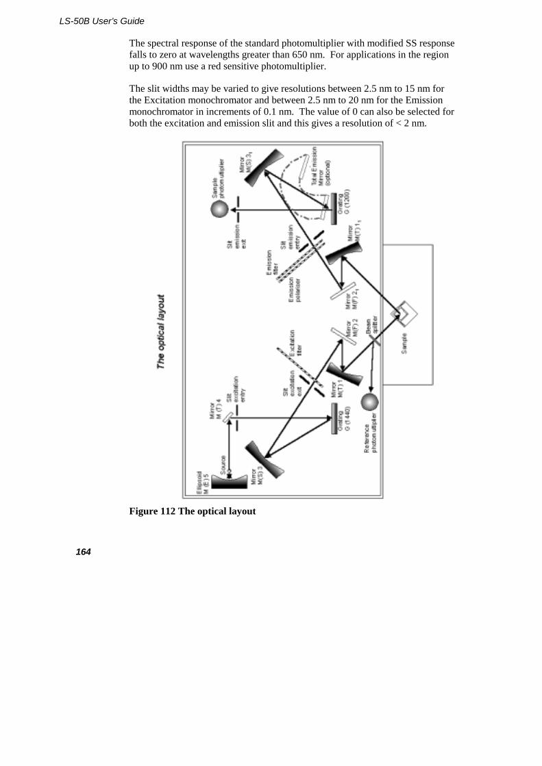
LS-50B User’s Guide
164
The spectral response of the standard photomultiplier with modified SS response falls to zero at wavelengths greater than 650 nm. For applications in the region up to 900 nm use a red sensitive photomultiplier.
The slit widths may be varied to give resolutions between 2.5 nm to 15 nm for the Excitation monochromator and between 2.5 nm to 20 nm for the Emission monochromator in increments of 0.1 nm. The value of 0 can also be selected for both the excitation and emission slit and this gives a resolution of < 2 nm.
Figure 112 The optical layout
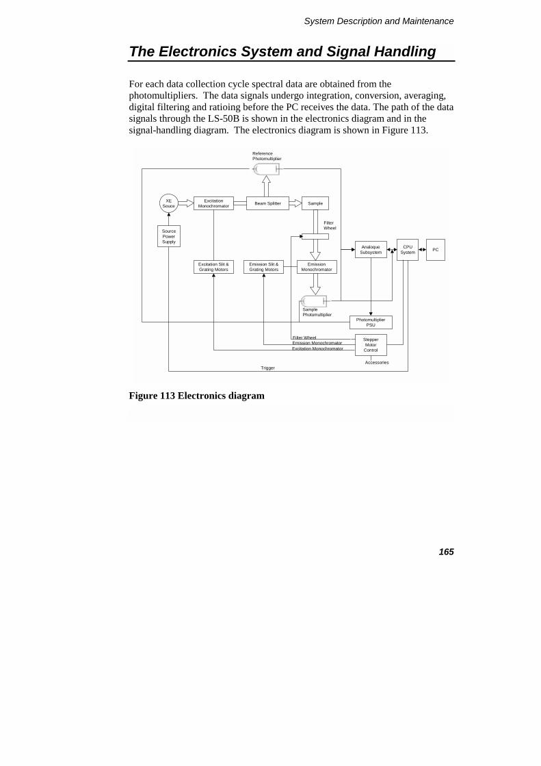
System Description and Maintenance
165
The Electronics System and Signal Handling
For each data collection cycle spectral data are obtained from the photomultipliers. The data signals undergo integration, conversion, averaging, digital filtering and ratioing before the PC receives the data. The path of the data signals through the LS-50B is shown in the electronics diagram and in the signal-handling diagram. The electronics diagram is shown in Figure 113.
CPUSystem PC
StepperMotor
Control
ReferencePhotomultiplier
SamplePhotomultiplier
Excitation MonochromatorEmission MonochromatorFilter Wheel
Accessories
XESouce
ExcitationMonochromator SampleBeam Splitter
EmissionMonochromator
AnaloqueSubsystem
PhotomultiplierPSU
Emission Slit &Grating Motors
Excitation Slit &Grating Motors
FilterWheel
SourcePowerSupply
Trigger
Figure 113 Electronics diagram
LS-50B User’s Guide
166
Instrument Modes
Fluorescence
When the instrument is operating in the fluorescence mode four integrations are performed for every data collection cycle. Two integrations are taken from the emission channel and two from the excitation channel. These integrations are performed at fixed times with respect to the last source flash.
An integration is taken of both the excitation and emission main signals. Emission from the source has a width at half peak height of less than 10 microseconds, the integrators are opened for 80 microseconds to collect all the signal. The effect of dark current (signal produced when no light is falling on the photomultiplier) is eliminated by gating open both channels a second time just before the next flash and integrating the signal. The dark current signals are then subtracted from the main fluorescence signals to give a dark current corrected signal.
Phosphorescence
When the instrument is operating in the phosphorescence mode the emission integration time is not fixed, but can be selected by the user. The integration can be started between 0 seconds and 9000 milliseconds after the start of the flash. This is the delay time. The time period over which the integration is performed, the gate time, can be varied from 0.01 milliseconds to 500 milliseconds. If the sum of the delay and gate times exceeds 13.0 milliseconds the cycle time must be increased to allow a longer data collection period.
The source can be pulsed between 1 and 10 times, to optimize the sample excitation and data collection. The exciting pulses occur on consecutive mains cycles at the start of the data collection cycle. The gate and delay times are measured from the beginning of the last pulse in the excitation pulse train. On initiating a phosphorescence measurement the dark current is measured and the value stored and subtracted from all sample signals.
System Description and Maintenance
167
Chemi- and Bio-luminescence
When the instrument is operating in the chemi- or bio-luminescence mode the source is switched off. Data signals are therefore only received from the sample photomultiplier. The integration time ranges are the same as for phosphorescence, but the signal is not ratioed. On initiating a bioluminescence measurement the dark current is measured and the value stored and subtracted from all sample signals.
Signal Conversion
After integration the photomultiplier signals are multiplexed, fed into the auto-ranging amplifier and then into the 12-bit successive approximation Analogue to Digital (A-D) converter. The auto-ranging amplifier increases the gain of the signal to optimize the A-D conversion. The conversion is obtained by using a 12 bit DAC (digital to analogue) converter and a comparator, where a 12 bit word is successively approximated to the analogue signal, with the control loop being supervised by the on-board microprocessor. The dark current is digitally subtracted from the reference signal and likewise from the sample signal, to give a true zero.
The DAC is also used to drive the analogue outputs such as chart recorders and other accessories.
Block Averaging
During scanning, the signal from the data collection cycle is block averaged, the degree of averaging being dependent upon the scan speed selected and the data interval. If the number of collection cycles is a non-integer, then the block average width is set to the smaller integer value. With the default data interval of 0.5 nm, examples of the number of collection cycles that are averaged for various scan speeds is shown in the table below.
LS-50B User’s Guide
168
Scan Speed nm/min
Block Average Width (50 Hz)
Block Average Width (60 Hz)
30 50 60
120 12 15
480 3 3
1500 1 1
Time Drive
In the time drive mode the amount of block averaging is determined by the value of the response time specified. The amount of block averaging is adjusted (taking into consideration the operating frequency of the instrument) to produce a 2% to 98% response to step signals over the specified response time. The default response time is 0.5 seconds.
Ratioing and Correction
After the sample and reference channels have been block averaged, they are ratioed to improve the signal to noise and to remove source related artifacts. This ratioed output is then scaled to either the wavelength range scanned or the time scale chosen to give the corrected result. The results are multiplied by the rhodamine correction curve, which is stored in the instrument, to correct for the spectral response of the photomultiplier tubes and the transmission response of the beamsplitter.
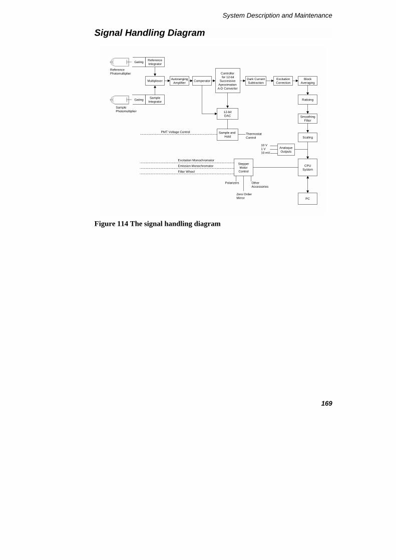
System Description and Maintenance
169
Signal Handling Diagram
Gating ReferenceIntegrator
Multiplexer
Gating SampleIntegrator
AutorangingAmplifier Comperator
Controller for 12-bit
SuccessiveAproximationA-D Converter
12-bitDAC
Dark CurrentSubtraction
ExcitationCorrection
BlockAveraging
Ratioing
SmoothingFilter
Scaling
CPUSystem
PC
AnaloqueOutputs
10 V1 V10 mV
Sample and Hold
PMT Voltage Control ThermostatControl
StepperMotor
Control
ReferencePhotomultiplier
SamplePhotomultiplier
Excitation Monochromator
Emission Monochromator
Filter Wheel
Polarizers
Zero OrderMirror
Other Accessories
Figure 114 The signal handling diagram
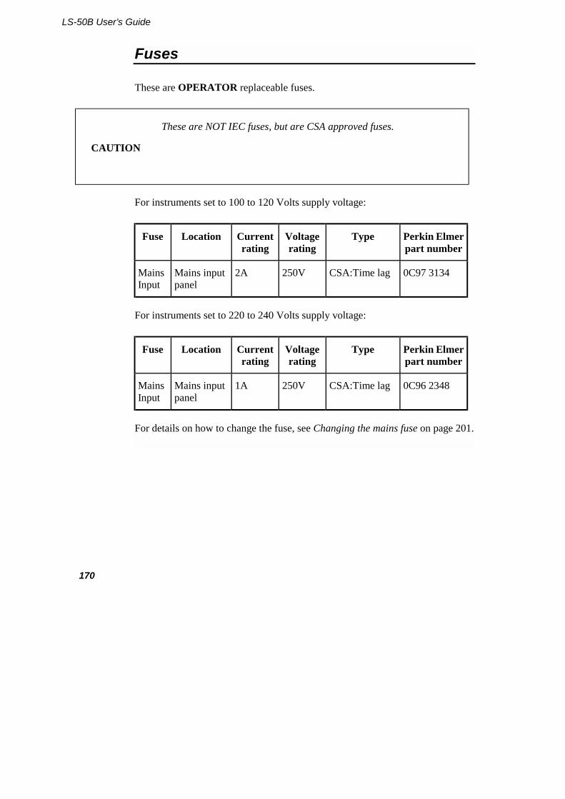
LS-50B User’s Guide
170
Fuses
These are OPERATOR replaceable fuses.
CAUTION
These are NOT IEC fuses, but are CSA approved fuses.
For instruments set to 100 to 120 Volts supply voltage:
Fuse Location Current rating
Voltage rating
Type Perkin Elmer part number
Mains Input
Mains input panel
2A 250V CSA:Time lag 0C97 3134
For instruments set to 220 to 240 Volts supply voltage:
Fuse Location Current rating
Voltage rating
Type Perkin Elmer part number
Mains Input
Mains input panel
1A 250V CSA:Time lag 0C96 2348
For details on how to change the fuse, see Changing the mains fuse on page 201.
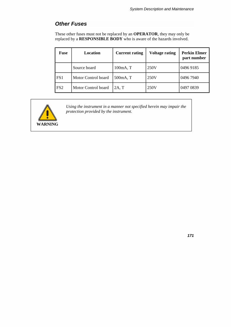
System Description and Maintenance
171
Other Fuses
These other fuses must not be replaced by an OPERATOR, they may only be replaced by a RESPONSIBLE BODY who is aware of the hazards involved.
Fuse Location Current rating Voltage rating Perkin Elmer part number
Source board 100mA, T 250V 0496 9185
FS1 Motor Control board 500mA, T 250V 0496 7940
FS2 Motor Control board 2A, T 250V 0497 0839
WARNING
Using the instrument in a manner not specified herein may impair the protection provided by the instrument.

LS-50B User’s Guide
172
Removing the Main Cover
Removing this cover will give access to hazardous voltages.
WARNING
Any adjustment, maintenance, or repair of the opened, operating instrument, must be performed by a skilled person who is aware of the hazards involved (a RESPONSIBLE BODY).
The main cover is hinged along the rear edge of the instrument.
1. Switch off the instrument and disconnect the electrical mains supply.
2. Position the LS-50B on the front of the bench so that it overhangs the bench by approximately 8 cm.
3. Loosen the two screws located on the left-hand and right-hand underside of the instrument, as shown in Figure 115. They are captive so will remain in the instrument.
Figure 115 Cover locking screws
4. Open the sample compartment cover.
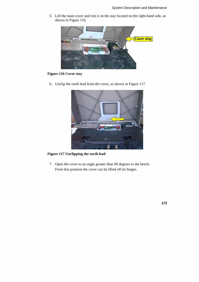
System Description and Maintenance
173
5. Lift the main cover and rest it on the stay located on the right-hand side, as shown in Figure 116.
Figure 116 Cover stay
6. Unclip the earth lead from the cover, as shown in Figure 117.
Figure 117 Unclipping the earth lead
7. Open the cover to an angle greater than 90 degrees to the bench. From this position the cover can be lifted off its hinges.

LS-50B User’s Guide
174
Refitting the main cover
To replace the cover proceed as follows:
1. Place the cover on its hinges.
2. Close the cover slightly and attach the earth lead.
3. Close the cover and tighten the screws to secure the cover.
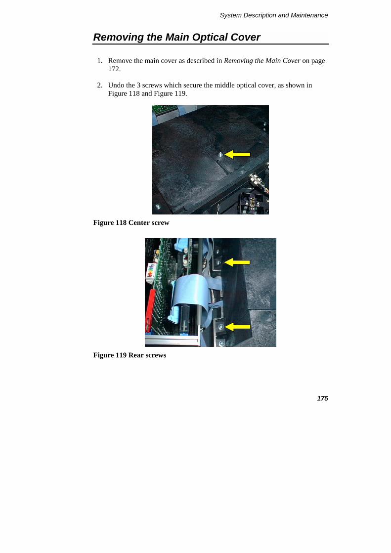
System Description and Maintenance
175
Removing the Main Optical Cover
1. Remove the main cover as described in Removing the Main Cover on page 172.
2. Undo the 3 screws which secure the middle optical cover, as shown in Figure 118 and Figure 119.
Figure 118 Center screw
Figure 119 Rear screws

LS-50B User’s Guide
176
3. Remove the middle optical cover by lifting it vertically, as shown in Figure 120.
Figure 120 Lifting the cover
CAUTION
Be careful not to touch any of the optical surfaces (mirrors or windows).
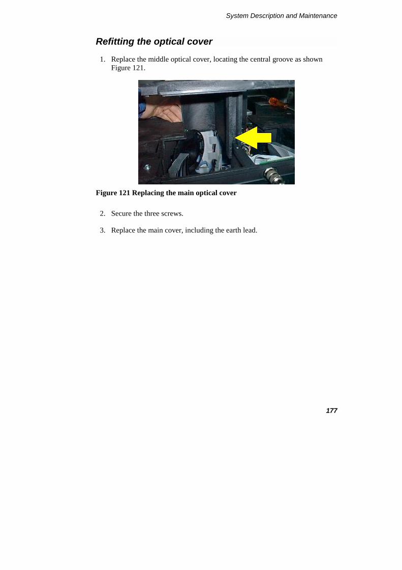
System Description and Maintenance
177
Refitting the optical cover
1. Replace the middle optical cover, locating the central groove as shown Figure 121.
Figure 121 Replacing the main optical cover
2. Secure the three screws.
3. Replace the main cover, including the earth lead.
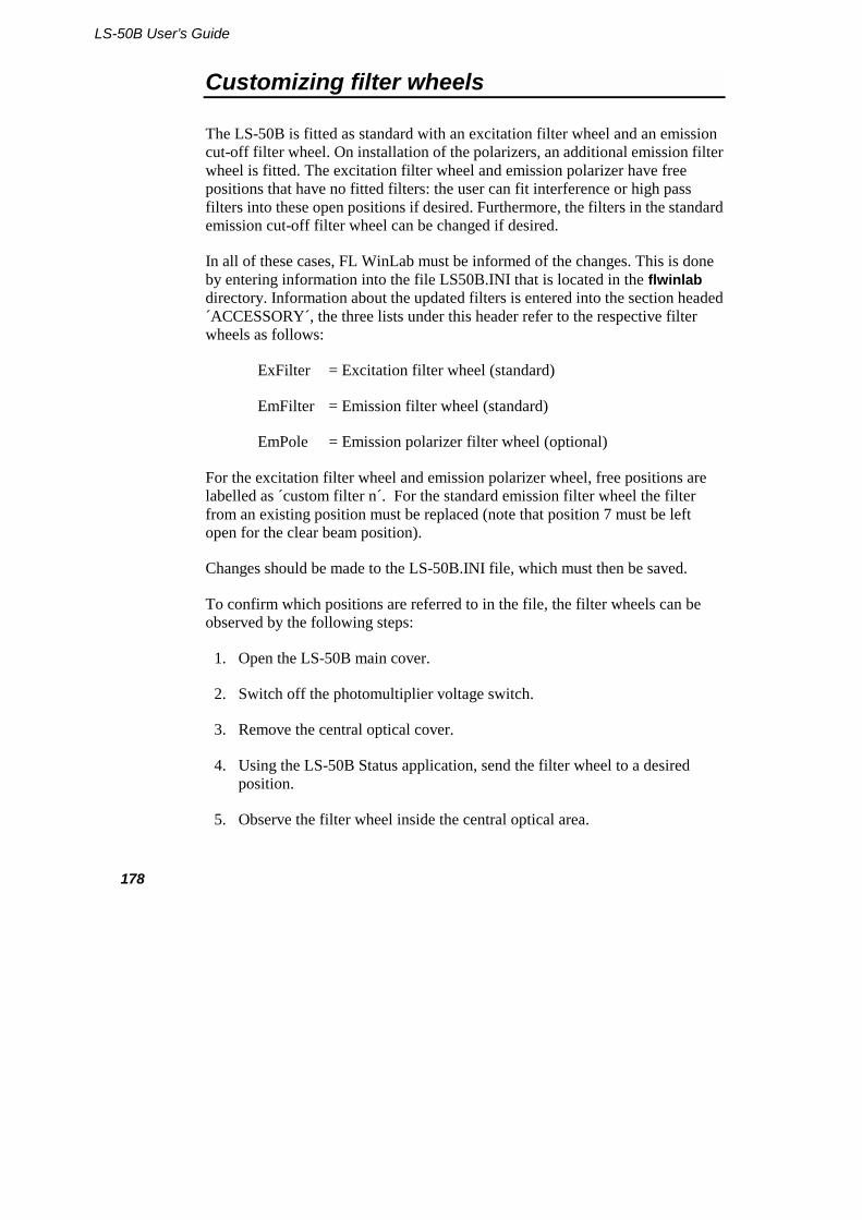
LS-50B User’s Guide
178
Customizing filter wheels
The LS-50B is fitted as standard with an excitation filter wheel and an emission cut-off filter wheel. On installation of the polarizers, an additional emission filter wheel is fitted. The excitation filter wheel and emission polarizer have free positions that have no fitted filters: the user can fit interference or high pass filters into these open positions if desired. Furthermore, the filters in the standard emission cut-off filter wheel can be changed if desired.
In all of these cases, FL WinLab must be informed of the changes. This is done by entering information into the file LS50B.INI that is located in the flwinlab directory. Information about the updated filters is entered into the section headed ´ACCESSORY´, the three lists under this header refer to the respective filter wheels as follows:
ExFilter = Excitation filter wheel (standard)
EmFilter = Emission filter wheel (standard)
EmPole = Emission polarizer filter wheel (optional)
For the excitation filter wheel and emission polarizer wheel, free positions are labelled as ´custom filter n´. For the standard emission filter wheel the filter from an existing position must be replaced (note that position 7 must be left open for the clear beam position).
Changes should be made to the LS-50B.INI file, which must then be saved.
To confirm which positions are referred to in the file, the filter wheels can be observed by the following steps:
1. Open the LS-50B main cover.
2. Switch off the photomultiplier voltage switch.
3. Remove the central optical cover.
4. Using the LS-50B Status application, send the filter wheel to a desired position.
5. Observe the filter wheel inside the central optical area.

System Description and Maintenance
179
NOTE: Many of the above steps are described graphically in the accessories section of this handbook.
The listing of the relevant section of LS50B.INI follows. Open filter wheel positions are shown in bold and italic script:
[ACCESSORY] PMT_Type=std ExFilter 1=clear (auto cutoff on) ExFilter 2=vertical polariser ExFilter 3=horizontal polariser ExFilter 4=blank
ExFilter 5=custom filter 1 ExFilter 6=auto ex cut off filter ExFilter 7=custom filter 2 ExFilter 8=UG 5 ExFilter 9=clear (auto cutoff off) EmFilter 1=290nm Cut-off EmFilter 2=350nm Cut-off EmFilter 3=390nm Cut-off EmFilter 4=430nm Cut-off EmFilter 5=515nm Cut-off EmFilter 6=closed EmFilter 7=open EmFilter 8=1%T attenuator EmPole 1=clear EmPole 2=vertical polariser EmPole 3=horizontal polariser EmPole 4=blank EmPole 5=custom filter 1 EmPole 6=custom filter 2 EmPole 7=custom filter 3 EmPole 8=custom filter 4
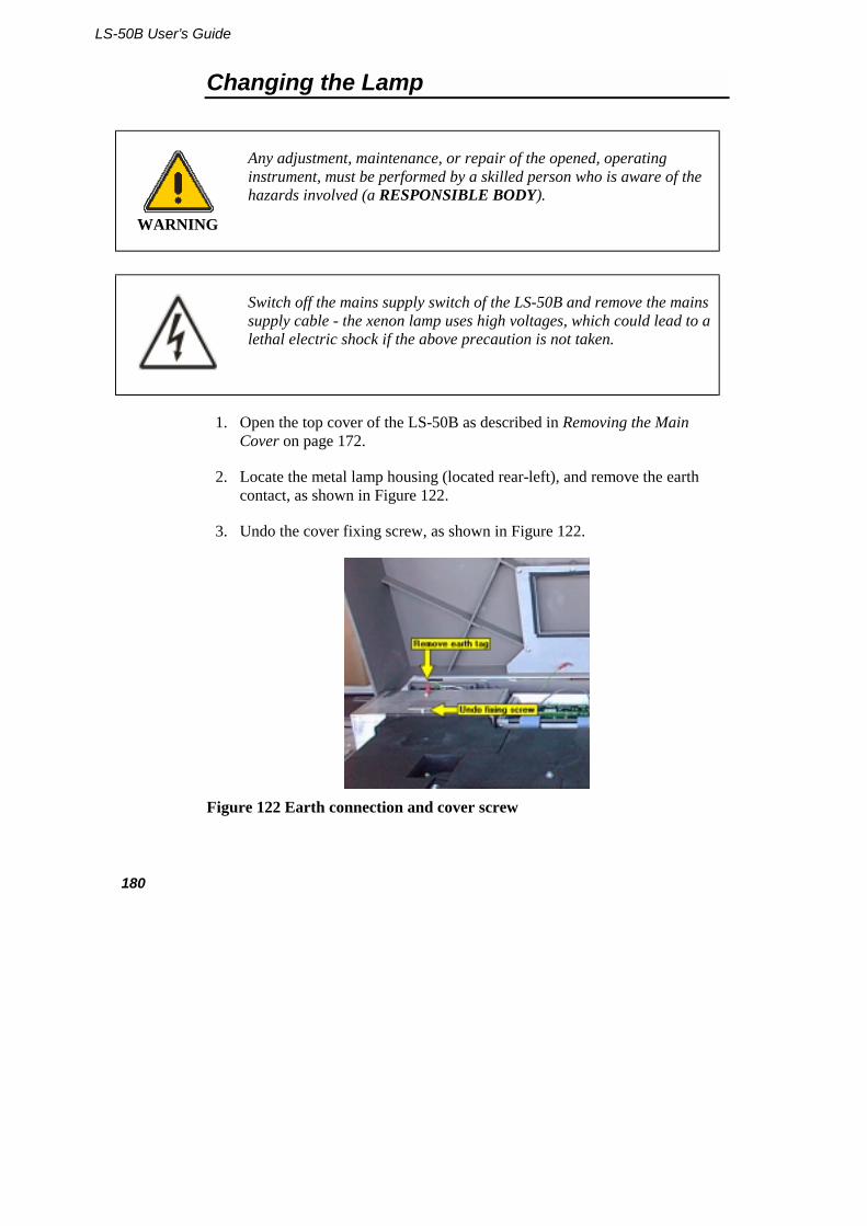
LS-50B User’s Guide
180
Changing the Lamp
WARNING
Any adjustment, maintenance, or repair of the opened, operating instrument, must be performed by a skilled person who is aware of the hazards involved (a RESPONSIBLE BODY).
Switch off the mains supply switch of the LS-50B and remove the mains supply cable - the xenon lamp uses high voltages, which could lead to a lethal electric shock if the above precaution is not taken.
1. Open the top cover of the LS-50B as described in Removing the Main Cover on page 172.
2. Locate the metal lamp housing (located rear-left), and remove the earth contact, as shown in Figure 122.
3. Undo the cover fixing screw, as shown in Figure 122.
Figure 122 Earth connection and cover screw

System Description and Maintenance
181
4. Lift the metal cover vertically away from the LS-50B, as shown in Figure 123, and store it securely.
Figure 123 Lifting the cover
5. Locate the lamp and the two electrode connectors, as shown in Figure 124.
Figure 124 Locating the parts
6. Press each connector in turn and remove the cables, as shown in Figure 125.

LS-50B User’s Guide
182
Figure 125 Disconnecting the cables
7. Loosen the grub screw at the bottom of the lamp holder bracket, as shown in Figure 126.
Figure 126 Loosen the grub screw
8. When the screw is correctly loosened, the lamp can be easily pulled vertically out of its bracket.
NOTE: If force is required, then the screw is still not loose enough.
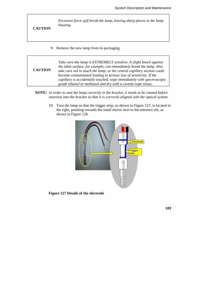
System Description and Maintenance
183
CAUTION
Excessive force will break the lamp, leaving sharp pieces in the lamp housing.
9. Remove the new lamp from its packaging.
CAUTION
Take care-the lamp is EXTREMELY sensitive. A slight knock against the table surface, for example, can immediately break the lamp. Also take care not to touch the lamp, or the central capillary section could become contaminated leading to serious loss of sensitivity. If the capillary is accidentally touched, wipe immediately with spectroscopic grade ethanol or methanol and dry with a cuvette-wipe tissue.
NOTE: In order to seat the lamp correctly in the bracket, it needs to be rotated before insertion into the bracket so that it is correctly aligned with the optical system.
10. Turn the lamp so that the trigger strip, as shown in Figure 127, is located to the right, pointing towards the small mirror next to the entrance slit, as shown in Figure 128.
Figure 127 Details of the electrode

LS-50B User’s Guide
184
Figure 128 Aligning the electrode
11. Insert the new lamp into the lamp holder bracket. There should be little resistance, but if this is not the case, loosen off the grub screw.
CAUTION
Use of excessive force when inserting the new lamp will most probably break it.
12. When the lamp has been fully inserted into the bracket, gently tighten the grub screw.
NOTE: The grub screw does not need to be overtight. Once the grub screw makes contact with the lamp post, this is tight enough. Overtightening could lead to scoring on the column of the lamp, making future removal difficult.
13. Connect both electrode cables by depressing the connector, inserting the cable, and releasing the connector, as shown in Figure 129.
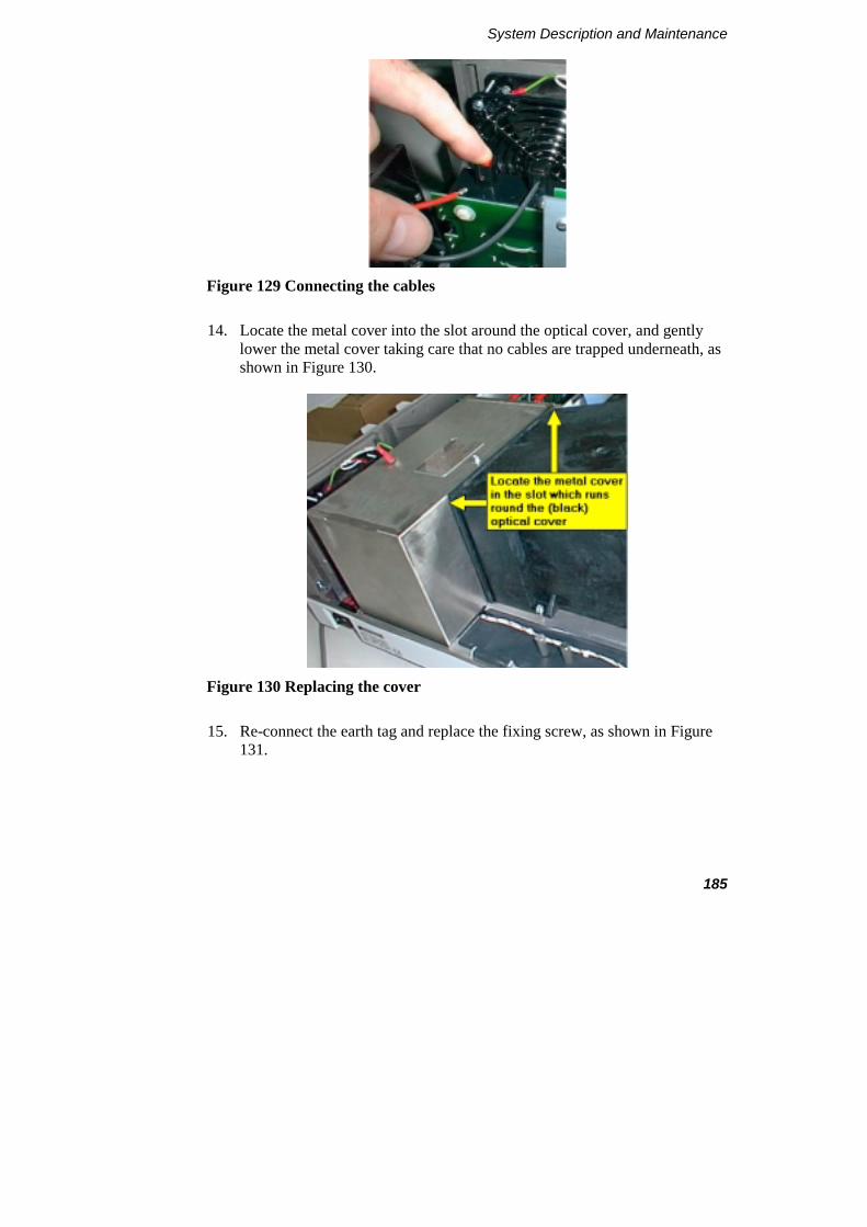
System Description and Maintenance
185
Figure 129 Connecting the cables
14. Locate the metal cover into the slot around the optical cover, and gently lower the metal cover taking care that no cables are trapped underneath, as shown in Figure 130.
Figure 130 Replacing the cover
15. Re-connect the earth tag and replace the fixing screw, as shown in Figure 131.

LS-50B User’s Guide
186
Figure 131 Earth lead and fixing screw
16. Close the main instrument cover.
17. Plug in the mains supply cable and switch on the LS-50B.
The performance of the LS-50B with the new lamp fitted can be tested using the FL WinLab validation routine. A silica cuvette with deionized water is inserted into the cuvette holder, and then the routine is started by selecting Validate LS-50B on the Applications menu in FL WinLab.
The routine will prompt you for the water-filled cuvette, then will measure and display the signal-to-noise value for the instrument, and the wavelength accuracy.
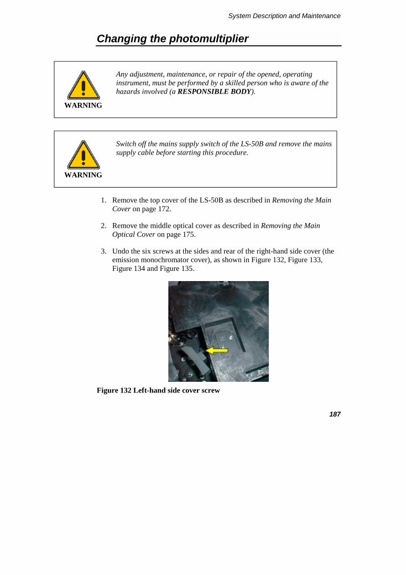
System Description and Maintenance
187
Changing the photomultiplier
WARNING
Any adjustment, maintenance, or repair of the opened, operating instrument, must be performed by a skilled person who is aware of the hazards involved (a RESPONSIBLE BODY).
WARNING
Switch off the mains supply switch of the LS-50B and remove the mains supply cable before starting this procedure.
1. Remove the top cover of the LS-50B as described in Removing the Main Cover on page 172.
2. Remove the middle optical cover as described in Removing the Main Optical Cover on page 175.
3. Undo the six screws at the sides and rear of the right-hand side cover (the emission monochromator cover), as shown in Figure 132, Figure 133, Figure 134 and Figure 135.
Figure 132 Left-hand side cover screw

LS-50B User’s Guide
188
Figure 133 Center in-board fixing screw
Figure 134 Rear in-board fixing screw

System Description and Maintenance
189
Figure 135 Three screws on the outer right side of the cover
CAUTION
Be careful to remove the cover VERTICALLY, to avoid damaging the delicate slit blades.
4. Lift the right side optical cover vertically off the base plate. The cover may stick slightly to the base plate due to the light-tight sealing.
CAUTION
Ensure that while the emission monochromator is open, the emission grating coarse sensor arm, as shown in Figure 136, is not accidentally knocked and bent out of shape. If this happens, then the coarse sensor arm may not actuate the coarse sensor switch on initialization, leading to errors in the emission wavelength position.
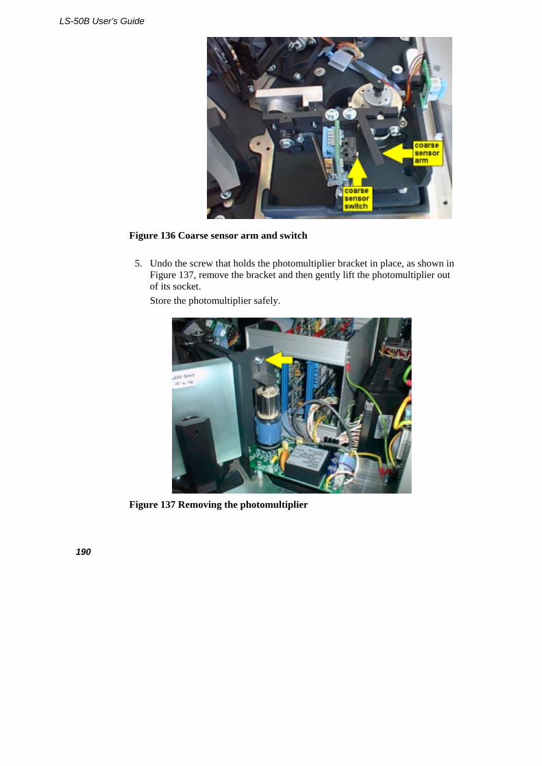
LS-50B User’s Guide
190
Figure 136 Coarse sensor arm and switch
5. Undo the screw that holds the photomultiplier bracket in place, as shown in Figure 137, remove the bracket and then gently lift the photomultiplier out of its socket. Store the photomultiplier safely.
Figure 137 Removing the photomultiplier

System Description and Maintenance
191
6. Locate the guide pin under the replacement photomultiplier, as shown in Figure 138, into the slot in the base plate, and press the photomultiplier gently into its socket. The photomultiplier can only be inserted into its base plate in one orientation.
Figure 138 Photomultiplier guide pin
7. Replace the photomultiplier bracket behind the screw, as shown in Figure 139.
Figure 139 Replacing the bracket
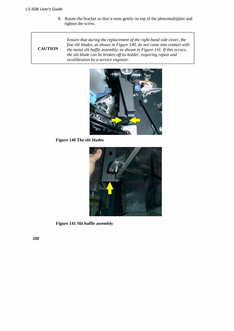
LS-50B User’s Guide
192
8. Rotate the bracket so that it rests gently on top of the photomultiplier and tighten the screw.
CAUTION
Ensure that during the replacement of the right-hand side cover, the fine slit blades, as shown in Figure 140, do not come into contact with the metal slit baffle assembly, as shown in Figure 141. If this occurs, the slit blade can be broken off its holder, requiring repair and recalibration by a service engineer.
Figure 140 The slit blades
Figure 141 Slit baffle assembly
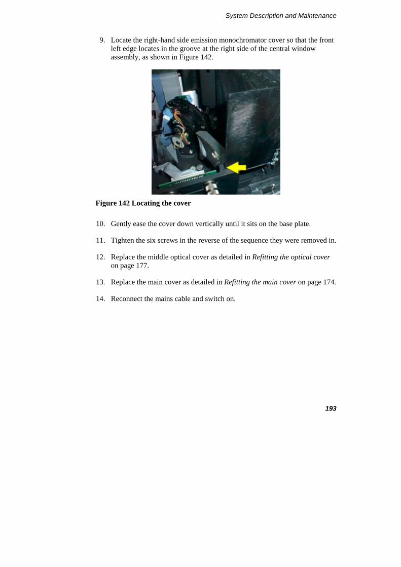
System Description and Maintenance
193
9. Locate the right-hand side emission monochromator cover so that the front left edge locates in the groove at the right side of the central window assembly, as shown in Figure 142.
Figure 142 Locating the cover
10. Gently ease the cover down vertically until it sits on the base plate.
11. Tighten the six screws in the reverse of the sequence they were removed in.
12. Replace the middle optical cover as detailed in Refitting the optical cover on page 177.
13. Replace the main cover as detailed in Refitting the main cover on page 174.
14. Reconnect the mains cable and switch on.

LS-50B User’s Guide
194
Preparing the LS-50B for transport
The LS-50B is extremely robust, and needs only to have its shipping clamps secured before transporting.
CAUTION
Always insert the shipping clamps before moving the LS-50B.
Never forget to remove the shipping clamps before switching on the LS-50B again - or the calibration of one or both monochromators could be severely corrupted leading to gross wavelength errors.
Inserting the clamps
1. Switch on the LS-50B and allow it to initialize fully. If the LS-50B is already running, then switch it off and on again. This is because the instrument is automatically driven to lock-down monochromator positions at the end of initialisation.
WARNING
Switch off the mains supply switch of the LS-50B and remove the mains supply cable before continuing this procedure.
2. Switch off the LS-50B and remove the mains supply cable.
3. Open the main cover as detailed in Removing the Main Cover on page 172.
4. Remove the two shipping clamp plates, by undoing the screws that hold them in place, as shown in Figure 143.
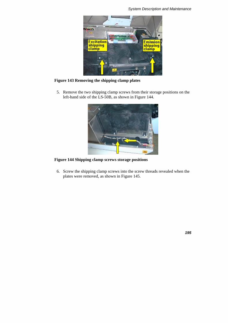
System Description and Maintenance
195
Figure 143 Removing the shipping clamp plates
5. Remove the two shipping clamp screws from their storage positions on the left-hand side of the LS-50B, as shown in Figure 144.
Figure 144 Shipping clamp screws storage positions
6. Screw the shipping clamp screws into the screw threads revealed when the plates were removed, as shown in Figure 145.
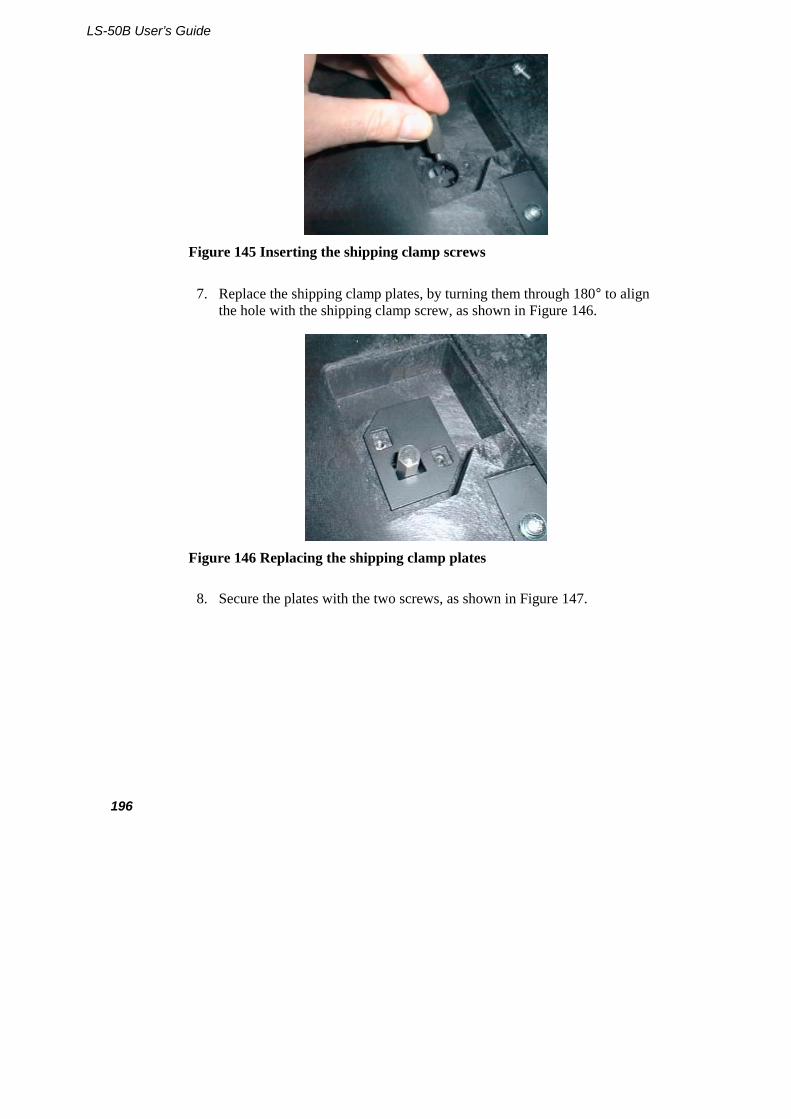
LS-50B User’s Guide
196
Figure 145 Inserting the shipping clamp screws
7. Replace the shipping clamp plates, by turning them through 180° to align the hole with the shipping clamp screw, as shown in Figure 146.
Figure 146 Replacing the shipping clamp plates
8. Secure the plates with the two screws, as shown in Figure 147.

System Description and Maintenance
197
Figure 147 Screwing down the plates
9. Close the main cover.
Lifting the LS-50B Luminescence Spectrometer
WARNING
Consult local codes of practice issued by safety advisors before attempting to lift the spectrometer.
As the LS-50B Luminescence Spectrometer weighs approximately 49 Kg (approximately 59 Kg with packaging), we recommend that the spectrometer is lifted by 2 adults, and that it is lifted by the base of the instrument.
Removing the clamps
Once the LS-50B has been moved to its new position, remove the clamps as detailed in Removal of the shipping clamps on page 27.
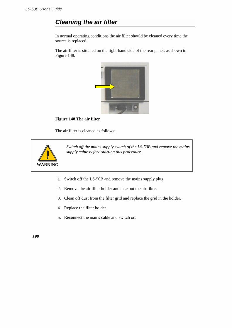
LS-50B User’s Guide
198
Cleaning the air filter
In normal operating conditions the air filter should be cleaned every time the source is replaced.
The air filter is situated on the right-hand side of the rear panel, as shown in Figure 148.
Figure 148 The air filter
The air filter is cleaned as follows:
WARNING
Switch off the mains supply switch of the LS-50B and remove the mains supply cable before starting this procedure.
1. Switch off the LS-50B and remove the mains supply plug.
2. Remove the air filter holder and take out the air filter.
3. Clean off dust from the filter grid and replace the grid in the holder.
4. Replace the filter holder.
5. Reconnect the mains cable and switch on.

System Description and Maintenance
199
Changing the Instrument Operating Voltage
WARNING
Any adjustment, maintenance, or repair of the opened, operating instrument, must be performed by a skilled person who is aware of the hazards involved (a RESPONSIBLE BODY).
WARNING
Switch off the mains supply switch of the LS-50B and remove the mains supply cable before starting this procedure.
The operating voltage of the instrument can be changed by altering the connections on the mains transformer, located inside the instrument.
1. Switch off the instrument and disconnect the electrical mains supply.
2. Open the main cover as detailed in Removing the Main Cover on page 172.
CAUTION
Do not change any of the terminal connections on the right-hand side of the transformer (viewed from the front of the instrument).
The mains transformer is located at the rear of the instrument. On the left-hand side of the transformer (viewed from the front) are five terminals with the voltages they each correspond to marked on the top of the transformer, as shown in Figure 149.
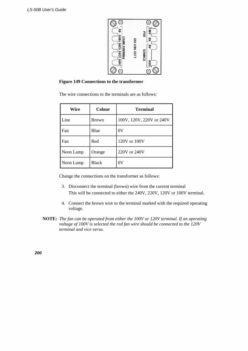
LS-50B User’s Guide
200
Figure 149 Connections to the transformer
The wire connections to the terminals are as follows:
Wire Colour Terminal
Line Brown 100V, 120V, 220V or 240V
Fan Blue 0V
Fan Red 120V or 100V
Neon Lamp Orange 220V or 240V
Neon Lamp Black 0V
Change the connections on the transformer as follows:
3. Disconnect the terminal (brown) wire from the current terminal This will be connected to either the 240V, 220V, 120V or 100V terminal.
4. Connect the brown wire to the terminal marked with the required operating voltage.
NOTE: The fan can be operated from either the 100V or 120V terminal. If an operating voltage of 100V is selected the red fan wire should be connected to the 120V terminal and vice versa.
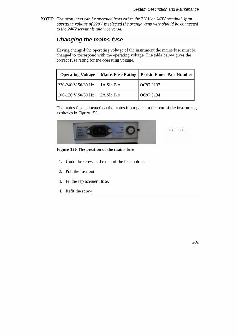
System Description and Maintenance
201
NOTE: The neon lamp can be operated from either the 220V or 240V terminal. If an operating voltage of 220V is selected the orange lamp wire should be connected to the 240V terminals and vice versa.
Changing the mains fuse
Having changed the operating voltage of the instrument the mains fuse must be changed to correspond with the operating voltage. The table below gives the correct fuse rating for the operating voltage.
Operating Voltage Mains Fuse Rating Perkin Elmer Part Number
220-240 V 50/60 Hz 1A Slo Blo OC97 3107
100-120 V 50/60 Hz 2A Slo Blo OC97 3134
The mains fuse is located on the mains input panel at the rear of the instrument, as shown in Figure 150.
Figure 150 The position of the mains fuse
1. Undo the screw in the end of the fuse holder.
2. Pull the fuse out.
3. Fit the replacement fuse.
4. Refit the screw.
Fuse holder

LS-50B User’s Guide
202
The mains voltage plate
NOTE: The mains voltage plate (on the mains input panel) must always indicate the voltage to which the instrument is set.
The mains voltage plate is double sided and it must be turned over when the voltage range is changed to correspond with the new setting. The voltage plate is secured by two screws, which also secure the mains socket. To change the voltage plate, proceed as follows.
1. Remove the two screws from the mains socket.
2. Carefully pull out the mains socket a small distance so that the voltage plate is released.
3. Turn the plate over and reposition behind the mains socket.
4. Push the mains socket back into place and replace the two screws.
The LS-50B can now be connected to the alternate mains voltage.

Index 7


Index
205
Index
A
About This Manual ......................15 accessories
cellchanger ...............................41 cellholders ....................39, 40, 42 external fibre optic ...................92 fast filter ...................................99 flowcell ....................................44 front surface .............................67 LC flowcell ..............................64 perfusion coverslip...................74 plate reader...............................78 polarizer .................................110 red sensitive detector................88 sipper........................................58 spares......................................116 total emission ...........................90
accessory connectors....................30 air filter.......................................198 analogue output commands........126 autosampler connection................33
B
biokinetic accessory commands ..............................126
biokinetics accessory....................42
C
care of optical mirrors ..................56 cellholders
cleaning ....................................57 cellholders
biokinetics accessory................42 care of optical mirrors ..............56 minimizing volume ..................52 resistance to solvents................57 screw fitting flowcell ...............44 semi-micro cuvette...................53 septum injector.........................49
single position..........................39 stirred four position cellchanger
.............................................41 stirred semi-micro cuvette .......54 stirred single position...............40 stirrer bars ................................51 thermostatting tubing ...............46
changing the lamp......................180 changing the mains fuse.............201 changing the operating voltage ..199 changing the photomultiplier .....187 cleaning
cellholders................................57 cleaning the air filter ..................198 connecting to a PC.......................32 connections ..................................30
accessory connectors................30 autosamplers ............................33 chart recorders .........................32 connection to a PC...................32 event marks..............................33 mains supply ............................30 remote starts.............................33 RS232C connection .................32 scan busy..................................33 terminal block ..........................32
conventions ..................................15 definitions ................................18
Conventions text ...........................................15
customizing the filter wheels .....178
D
description electronics system..................165 fuses .......................................170 optical system ........................163 signal handling.......................165
LS-50B User’s Guide
206
E
electrical connections...................30 electronics system ......................165 environmental conditions...............9 event mark connection .................33 external fibre optic accessory.......92
F
fast filter accessory.......................99 commands ..............................127
filter motor commands ...............125 filter wheel .................................178 filters ..........................................178 four position cellchanger
commands ..............................126 front surface accessory.................67 fuse
changing.................................201 fuses ...........................................170
I
inserting the shipping clamps.....194 introduction ..................................23
L
lamp............................................180 LC flowcell ..................................64 lifting............................................26
M
main cover..................................172 mains fuse ..................................201 mains supply ................................30 mains voltage plate.....................202 maintenance
care of optical mirrors ..............56 changing the lamp ..................180 changing the mains fuse.........201 changing the operating voltage
............................................199 changing the photomultiplier .187 cleaning the air filter ..............198
customizing the filter wheels .178 main cover .............................172 main optical cover..................175 preparing for transport ...........194
moving .......................................194
O
opening the main cover..............172 operating voltage .......................199 operator ........................................18 optical system ............................163
P
perfusion coverslip accessory ......74 peristaltic pump
commands ..............................126 photomultiplier ..........................187
red sensitive .............................88 photomultiplier control commands
...............................................125 plate reader
commands ..............................126 driver commands ...................124
plate reader accessory ..................78 polarizer accessory.....................110 power switch................................35 preparing for transport ...............194
R
red sensitive detector ...................88 refitting the main cover..............174 refitting the main optical cover ..177 remote start connection................33 removing the main cover ...........172 removing the main optical cover175 removing the shipping clamps .....27 replacing the main cover............174 responsible body ..........................18 RS232 commands ......................119
analogue output......................126 command formats ..................128 fast filter accessory ................127

Index
207
filter motor .............................125 photomultiplier control ..........125 plate reader driver ..................124 sample aquisition....................126 slit motor ................................125 source control.........................125
RS232C communications...........122 RS232C connections....................32
S
safety information ..........................9 scan busy connection ...................33 screw-fitting flowcell ...................44 semi-micro cuvette.......................53 septum injector.............................49 shipping clamps............................27
inserting..................................194 shipping kit...................................25 signal handling ...........................165 single position cellholder .............39 sipper accessory ...........................58 slit motor commands..................125 software
anisotropy...............................115 filter setup ..............................107 polarization ............................115 sipper control ...........................61
well plate reader.......................85 source control commands ..........125 spares for accessories.................116 specifications ...............................19 standard cellholder.......................39 start up .........................................35 starting .........................................35 stirred four position cellchanger ..41 stirred semi-micro cuvette ...........54 stirred single position cellholder..40 stirrer bars ....................................51 stirring samples............................51 switching on.................................35
T
temperature control ......................46 terminal block ..............................32 thermostatting tubing ...................46 total emission accessory...............90
V
voltage........................................199
W
warning labels..............................11 well plate reader software ............85

LS-50B User’s Guide
208