Embed Size (px)
Citation preview

International Ten Rater Class Sail Measurement Procedure
A suggested method
What is this document for - 1bull The measurement of a boat or its equipment to establish that it complies
with the relevant class rules is a process much like any scientific experiment In a scientific experiment the physical measurements are taken with suitable equipment by the experimenter Best practice demands that the measurements are valid reliable and credible
bull For the measurement of a boat or its equipment the validity of the measurements is determined by the class rules and is therefore not determined by the the official measurer However the reliability and credibility are entirely under his control and both are of interest to everyone involved ndash owner sailor official measurer certification authority and fellow competitors
bull Without good reliability and credibility in the measurement process one of the basic principles of the sport that competitors are governed by a body of rules that they are expected to follow breaks down See RRS lsquoBasic Principlesrsquo
bull It should be self evident that it is important to establish what represents good design for the measurement equipment and good practice for its use This document seeks to identify one example of good design of measurement equipment and the good practice of its use
What is this document for - 2
bull The Royal Yachting Association the World Sailing Member National Authority for Great Britain maintains the lsquoRYA Racing Charterrsquo which is included in its copies of the RRS
bull One of the objectives of the RYA Racing Charter is
lsquoTo provide the framework for everyone to enjoy the sport of sailboat racing in whatever capacity and to whatever level the individual desiresrsquo
It goes on to state Principles and Practices that support the objectives One is
lsquoOfficials agree to provide the fairest racing possiblersquo
bull Official Measurers play an essential and important role in helping to maintain the framework that supports sailing and unless they carry out their tasks diligently the fairest racing will not be possible
bull The Certification Authority should support its Official Measurers by assisting them to carry out their role effectively Training in the process of equipment measurement is an essential part of this support
bull This document is provided by IRSA to aid that support
References - 1
The following documents are referred to in the slides
bull IRSA International Ten Rater Class rules 2018 -link
bull ERS ndash Equipment Rules of Sailing 2017-2020 -link
References - 2
The following documents will give valuable additional insight into the measurement process for the Ten RaterClass as well as for any other class
bull International Measurers Manual ndash published by World Sailing - link
bull Guidance for Equipment Inspection (event measurement) ndash published by IRSA - link
Contents
bull Preparation
bull Equipment
bull Setting up
bull Mast spar measurement ndash constant amp evenly tapered profiles
bull Mast spar measurement - other profiles
bull Spar used to extend the tack andor clew of sail measurement
bull Sail area measurement
bull Data entry
bull Round measurements correctly
bull Comparing dimensions with limits
bull Certification of the largest sails
bull Certification of smaller sails
bull Sail maker guidance
Preparation bull Set of Ten RaterClass Rules
bull Set of Ten RaterCertificate amp Certification Control Forms (electronic and hard copy for recording convenience) [boat data input sheet shown here]
The process of measuring the rig and sails of a Ten Rater can be carried out easily by one person
Whilst not essential at this stage it is useful to have a full set of certification control forms printed off and set of Ten Rater Class rules
Open a certificate spread sheet on the computer and delete all existing data Print this blank copy to record the measurements taken
Equipment - 1
bull Flat surface 2500 mm x 650 mm
bull Sailspar measurement grid
bull Caliper (Vernier) tape measure and straight edge rule (600 amp 300 mm)
bull Adhesive tapes for holding sail measurement grid to flat surface
bull Pens and pencils for recording data
bull Waterproof pen for certifying sails
This list should not be regarded as everything that is essential for a measuring session nor should it be viewed as a list of the absolute minimum requirements
Equipment - 2
Sailspar measurement grid
Use thick Mylar film 2450 mm x 600 mm to make the grid
Place a vertical line 50 mm from the right hand edge
Add grid lines at 200 mm spacing perpendicular to the first line numbered 0 to 11
Add vertical lines at 50 mm spacing below the lowest grid line and perpendicular to that grid line numbered 0 to 11
Setting UpPrepare grid
Tape the sailspar measurement grid to the flat surface using tabs of tape at the four corners
Mast spar measurement ndash constant amp evenly tapered profiles
Many mast spars are of constant cross section or are evenly tapered along their length
In these cases the area of the spar Am is calculated as
Am = h x (m0 + mn) 2
where
h is the length of the spar above deck
m0 is the fore-and-aft mast spar cross section or vertical boom spar cross section at one end
mn is the fore-and-aft mast spar cross section or vertical boom spar cross section at the other end
Mast spar measurement -other profiles ndash 1
Many mast spar have an irregular taper They are measured on the sailspar measurement grid
Mast spar shall be placed over the sailspar measurement grid perpendicular to the grid lines and with a grid line at deck level
See Figure L11 and L12 of the class rules
Mast spar measurement -other profiles - 2
Mast spars shall be placed over the measurement grid perpendicular to the grid lines and with a grid line at deck level
See Figure L11 and L12 of the class rules
In this example there is a fitting (the grey tube) on the mast spar at deck level
Mast spar measurement - 3
Mast spars shall be placed over the measurement grid perpendicular to the grid lines and with a grid line at deck level
See Figure L11 and L12 of the class rules
The leading edge of this mast spar is on the vertical line
Mast spar measurement - 4
The fore-and-aft mast sparcross sections m0 to mn shall be measured at and along all the grid lines that the spar cuts
In the example on the right a fitting occurs at the grid line ndash the measurement required is of the sparcross section (the main structural part of the mast) so ignore the fitting when taking the measurement
Mast spar measurement - 5
The area of spar above the uppermost gridline cutting the spar At is calculated as
At = 07 x mn x E
where E is the height of the spar above the uppermost grid line and mn
is the uppermost width
Ignore any fitting that is not faired into the mastspar E in this example is 130 mm
Mast spar measurement - 6
Fittings not faired into a spar and no bigger than is reasonably required for their purpose shall not be considered to be part of the spar
Fittings faired into a spar andor bigger than reasonably required for their purpose shall be considered to be part of the spar
If the backstay crane had been faired into the spar or was bigger than necessary it would be included in the E measurement
Measurement of spars used to extend the tackandor clew of sail
One spar with a maximum spar cross section not exceeding 22 mm may be used to extend the tack andor clew of each sail without being included in the certified rig area ndash see next page
Most rigs have only two spars of less than 22 mm cross section used to extend he tack andor clew of each sail In this case there will be no need to measure any such spars
In the case of ldquoclassic swing rigldquo area of the spar cantilevered from the mastto which the spar used to extend the tack and clew of the headsail isattached shall be included in the certified rig area
Any spar that shall be included in the certified rig area according to the class rule J1 shall be measured as for mast spars
Check whether or not the spar used to extend the tack andor clew of each sail needs to be included in the certified rig area - it is to be done in accordance with class rule J1(a) as shown here
If the area is to be included in the certified rig area then measure the vertical boom spar cross section mentioned in Class Rules J3 J4 and Figure L1 - to be taken as shown here
vertical boom spar
cross section
Maximum spar cross section measurement
Sail area measurement ndash 1
Some general points in the Class Rules that vary the approach required by the Equipment Rules of Sailing
bull Battens need not be removed from sails
bull Sails can be left on the spars ndash but it will be easier if they are removed
bull Stays inside luff tabling that are less than 2 mm in diameter need not be removed
bull Tell tales overlapping sail edges shall be ignored
Sail area measurement - 2
Some general points in the Class Rules that vary the approach required by the Equipment Rules of Sailing
Parts of a headboard that are less than 2 mm in diameter and not covered by sail material shall not be taken as parts of the sail
Where a sail has a luff rope the cross widths shall be taken to aft edge of the spar
Sail area measurement - 3
Discontinuous attachments on the luff shall be disregarded for the purpose of measurement provided that their total length measured along the luff does not exceed 10 of the luff length and that the longest attachment is no more than twice the shortest
Sail area measurement - 4
The sail shall be placed over the measurement grid with the clew point on the datum grid line (below left)and with the head point (right) and tack point (below right) on a line perpendicular to the grid lines See Figure L21
Sail area measurement - 5The upper limit of area A1 shall be marked at the luff and leech where they pass over the grid line See Figure L23 The illustration to the right shows the sail correctly positioned on the grid The illustration below shows the sail (moved) after marking
Sail area measurement - 6
Cross widths c0 to cn shall be measured from the leech to the luff at and along all the horizontal grid lines which the sail cuts See Figure L24
The cross width is 408 mm
Sail area measurement - 7
Heights h0 to hn shall be measured from the datum grid line to the foot at and along all the vertical grid lines which the sail cuts See Figure L24
Data entry - 1
The cross widths c0 to cn heights h0 to hn and the extensions at the head of each sail E are entered into the spreadsheet for the two sails and the area of each sail is found from those measurements
bull The uppermost cross width is always entered into the box marked cn
bull The aftermost height is always entered into the box marked hn
bull Whole number values only ndash no decimal places
IRSA - WORLD RADIO SAILING
IRSA 10 RATER CLASS SAIL CERTIFICATION CONTROL FORM89
Sail 1
E 50
cn 55
c10 cn-1 118
c9 118
c8 167 To maximise sail area
Either
c7 212
c6 265 Or
c5 295
c4 329
c3 361
c2 392
c1 316
SUM1 2455 +
c0 435
hn 9
h10
h9
h8 Warning box
h7 19
h6 27
h5 34
h4 40
h3 45 Warning box
h2 45
h1 35
SUM2 245 h0 12
A1 c0 + cn 490 x 100 49000 + 491000 A1 540000
SUM1 2455 x 200
A2 05 x E (cn x (2 + E 200) - E x cn-1 200) A2 2356
A3 h0 + hn 21 x 25 525 + 12250 A3 12775
SUM2 245 x 50
555131
DECLARATION BY THE MEASURER
Name of Official Measurer Stamp (Certification Authority)
(BLOCK CAPITALS)
Signature Date
Effective 1st April 2018 V 18-2 copy 2018 IRSA
IRSA Ten Rater Class Sail 1 CCF - Certificate page 2 - not valid without pages 1 3 and 4
435
435
NB These dimensions are approximate
and for guidance only
2062
18
Leech length
official validity check
2345Hull registration number
Delta Sail 1 LP
Foot
Guide measurements for sail makers and
Equipment Inspectors
Luff length
Delta Sail 2 LP
Equivalent to Sail 1 LP
24
2096
The measurer may report anything here
Equivalent to Sail 2 LP
I confirm that I have taken the measurements on this form that they are correct and that to the best of my knowledge the sail
complies with the class rules in force at present except as I have stated below
453
Luff perpendicular
428
S (sail1)
A1
A2
A3
Data entry - 2To the right hand side of the data entry area and below it are graphs that show the sail profile
0
100
200
300
400
500
-200 0 200 400 600 800 1000 1200 1400 1600 1800 2000 2200
cro
ss w
idth
s
distance above datum grid line at luff
Sail 1 cross widths
sail 1 profile
cross width differences
ERS Cross Widths
sail 1 foot
height differences x 10
bull The leech profile is shown by dark blue diamonds and a dark blue line
bull The foot profile is shown by red crosses on yellow squares and a bright blue line
bull The pink squares and a pink line show the changes in cross widths
bull The pinks squares on a blue line shown the changes in foot heights
Two errors in the data entry for the cross widths are obvious from the leech profile line The
cross width at 200 mm (C1) is probably 100 mm too small The cross width at 1200 mm (C6) is
probably 10 mm too large
Large irregularities appear at those places in the lsquochange in cross widthrsquo line
Data entry - 3
To the right hand side of the data entry area are
tables in yellow that check for hollows in the sail
leech and foot profiles
Because the data entry for C1 was 100 mm too
small the word lsquocheckrsquo appears against C1
Because the data entry for C6 is 10 mm too great
it appears there are hollows each side of C6 ie
the word lsquocheckrsquo appears at C5 and C7
The word lsquocheckrsquo also appears for h2 and h3 for
the foot profile A visual check of the graph shows
this may not be the case
Check the sails to establish the correct
dimensions and for any hollows where indicated
Hollows check
C11 0 0
C10 55 55 ok
C9 118 111 ok
C8 167 165 ok
C7 212 216 check
C6 265 254 ok
C5 295 297 check
C4 329 328 ok
C3 361 361 ok
C2 392 339 ok
C1 316 414 check
C0 435 158 ok
hn 9
h10 0 285
h9 0 40
h8 0 425
h7 19 395
h6 27 335
h5 34 265
h4 40 18
h3 45 95 check
h2 45 45 check
h1 35 0
h0 12
Measurer - Please check
for hollows where noted
Data entry - 4Checking the sail reveals 316 was entered instead of 416 at C1 and 265 was entered instead of 256 at C6 When these corrections are made the sail profile appears shown here
The lsquochange in cross widthsrsquo and lsquochange of foot heightsrsquo lines are now smooth
Note that there are three data points (orangered on a red line) that show the estimated ERS quarter half and three-quarter cross widths for the sail Not used for measurement but used for the sail maker guidance page
0
100
200
300
400
500
-200 0 200 400 600 800 1000 1200 1400 1600 1800 2000 2200
cro
ss w
idth
s
distance above datum grid line at luff
Sail 1 cross widths
sail 1 profile
cross width differences
ERS Cross Widths
sail 1 foot
height differences x 10
Data entry - 5Mast spars that are of constant diameter or have an even taper are measured by measuring the width at the heel point (m0) and the top point (mn) and the distance between those (h)
See the Spar2 area to the right hand side of the spar ndashpage 4 sheet
In the example here this calculation is used to find the area of a boom spar that is part of a swing rig that uses three boom spars in total It is 440 mm long and 12 mm deep
Masts that have an irregular profile are measured in the same way that sails are measured
This includes any spar that is made with a step lsquotaperrsquo using tubes of different diameters This mast is made of 16 14 and 12 mm tubes
0
2
4
6
8
10
12
14
16
18
0 500 1000 1500 2000
sp
ar
wid
th
height above deck level
spar 1 profile
spar 1 profile
spar 2 profile
IRSA - WORLD RADIO SAILING
IRSA 10 RATER CLASS SPAR CERTIFICATION CONTROL FORM
71
delete as appropriate delete as appropriate
Spar1
E 150 Constant and
x Evenly Tapered Profiles
mn 12 mn 12
x mn 12
top of main structural part of mast 07 +
m11 m0 12
m10 24
length x
m9 12 of main h 440
structural x
m8 14 part of 05
mast
m7 14 2150 Am 5280
for
m6 14 information S(spar2) 5280
only Warning box
m5 16
m4 16
m3 16
m2 16
m1 16
+ heel point
m0 16 deck level
At 1260
m0+mn 28 x 100 2800 + 26800 Am 29600
SUM3 134 x 200 S(spar1) 30860
S(spar2) 5280
Other spar areas - show calculations here or on another sheet S(other spar)
Area of spars for alternative rigs shall not exceed this area S(rig area) 36140
DECLARATION BY THE MEASURER
Name of Measurer Stamp (National Authority)
(BLOCK CAPITALS)
Signature Date
Effective 1st April 2018 V 18-2 copy 2018 IRSA
IRSA Ten Rater Class Sail 1 CCF - Certificate page 3 - not valid without pages 1 2 and 3
The measurer may report anything here
2345
Spar2
I confirm that I have taken the measurements on this form that they are correct and that to the best of my knowledge
the spar complies with the class rules in force at present except as I have stated below
official validity check Hull registration number
Data entry - 6The length of the mast spar is calculated from the data and is shown near the middle of the page shown here
It is useful to make a quick check by measuring the approximate length of the mast This ensures no data entry is missed out
The mast spar length is compared with the mainsail luff length If it is shorter than the mainsail luff length a note to that effect is shown in one of the lsquowarning boxesrsquo
IRSA - WORLD RADIO SAILING
IRSA 10 RATER CLASS SPAR CERTIFICATION CONTROL FORM
71
delete as appropriate delete as appropriate
Spar1
E 150 Constant and
x Evenly Tapered Profiles
mn 12 mn 12
x mn 12
top of main structural part of mast 07 +
m11 m0 12
m10 24
length x
m9 12 of main h 440
structural x
m8 14 part of 05
mast
m7 14 2150 Am 5280
for
m6 14 information S(spar2) 5280
only Warning box
m5 16
m4 16
m3 16
m2 16
m1 16
+ heel point
m0 16 deck level
At 1260
m0+mn 28 x 100 2800 + 26800 Am 29600
SUM3 134 x 200 S(spar1) 30860
S(spar2) 5280
Other spar areas - show calculations here or on another sheet S(other spar)
Area of spars for alternative rigs shall not exceed this area S(rig area) 36140
DECLARATION BY THE MEASURER
Name of Measurer Stamp (National Authority)
(BLOCK CAPITALS)
Signature Date
Effective 1st April 2018 V 18-2 copy 2018 IRSA
IRSA Ten Rater Class Sail 1 CCF - Certificate page 3 - not valid without pages 1 2 and 3
The measurer may report anything here
2345
Spar2
I confirm that I have taken the measurements on this form that they are correct and that to the best of my knowledge
the spar complies with the class rules in force at present except as I have stated below
official validity check Hull registration number
Round measurements correctly
Always round up to the next whole number
ldquoLinear measurements shall be taken in millimetres and rounded up to the nearest whole numberhelliprdquo
For example a value judged to be just over 2080 mm say 2081 mm shall be rounded to 209 before being used on the certificate
Comparing dimensions with limits
Limits are not flexible
ldquoMaximum and minimum values of limitations in the class rules or certificate shall be taken as absolute limiting valuesrdquo
For example a boom spar with a spar cross section judged to be just over 220 mm say 221 mm is over the 22 mm limit above which its area shall be included in the certified rig area
Certification of the largest sails
Usually the largest sails and mast spar are measured first to establish the rating of the boat After completing thishellip
The official measurer shall add following at the tack
bull a certification mark (usually his signature) as a proof of successful certification control
bull the date of certification control (usually todayrsquos date)
bull the area of each sail hellip(look on the spreadsheet for the relevant sail ndash in square metres to 3 places of decimals eg 0644 )
Certification of smaller sails - 1Other sails shall comply with the dimensions of their lsquoparentrsquo sail recorded on the certificate
Their dimensions are found in the same way as for the parent sail with one exception
bull The sail may be moved vertically on the grid to achieve compliance
This is because the tack point (especially for headsails) will usually extend below the h0 dimension when its clew point is placed on the grid line In this case the sail is moved up the vertical grid line until the tack point is at the dimension recorded on the certificate (or further if necessary) Then the cross widths and heights can be taken and compared with the certificate values
Certification of smaller sails - 2
The sail may be moved vertically on the grid to achieve complianceNote that even though the clew point of the smaller sail extends beyond the actual profile of the largest measured sail its cross width and height measurements comply with those of the largest measured sail It is compliant
Certification of smaller sails - 3When the smaller sails have been checked and found to comply with the dimensions of their parent sailshellip
The official measurer shall add following at the tack
bull a certification mark (usually his signature) as a proof of successful certification control
bull the date of certification control (usually todayrsquos date)
bull the area of parent mainsail and headsail (look on the spreadsheet for the relevant sail ndash in square metres to 3 places of decimals eg 0644 ) for each alternative mainsailand headsail
Sail maker guidance - 1
This sheet is not part of the certification process but is created to log information that will be useful to the sail maker when making replacement sails to match the certificate for the boat
Data from the data entry amp rating calculation sheet appears on the sheet to identify the boat and owner
The primary dimensions of each sail including the ERS quarter halfand three-quarter cross widths are shown
The sail maker will also need copies of sail 1 ndash page 2 and sail 2 ndash page 3 from the certificate to ensure the sail is shaped exactly to match the certificate
IRSA - WORLD RADIO SAILING
IRSA 10 RATER CLASS SAIL MAKER GUIDANCE
Guide measurements for sail makers and Equipment Inspectors
NB These dimensions are approximate and for guidance only
The dimensions of sails shall not exceed the dimensions of the sails recorded on the certificate
Hull Reg No 2345 Dimension Sail 1 Sail 2
Boat Name Power Point Luff 2062 1575
Design Name High Voltage Leech 2096 1505
Owners Name A Powers three-q 177 140
Sails Measured 01 May 2018 half 287 244
96 Validity check quarter 373 336
LP 435 404
Foot 435 423
three quarter width Use with caution
025 LP plus 68
three quarter width To maximise sail area
025 LP Rating 9994
plus Max permitted sail area 0987362
39 Measured sail area 0986809
Deficit - m^2 0000553
Deficit - mm^2 553
half width Either
05 LP plus 70 Delta Sail 1 LP 1
half width Equivalent to Sail 1 LP 436
05 LP Or
plus Delta Sail 2 LP 1
42 Equivalent to Sail 2 LP 405
quarter width
075 LP plus 47 quarter width
075 LP
plus
33
Sail 1
Sail 2
Luff
Leech
LP
Sail 1
Sail 2
Leech
LP
Sail maker guidance - 2
The difference between the measured area of the rig and the maximum permitted area (Deficit) is shown in units of square metres and square millimetres
The deficit for this boat is 553 mm^2
To assist the owner maximising his sail area for future measurement a lsquonewrsquo dimension is found for Sail 1 LP and Sail 2 LP that will provide the additional sail area The quarter half and three-quarter cross widths have to be increased in correct proportion
In this case the increase in mainsail foot length (Delta Sail 1 LP) is 1 mm It is 553(05 x 2062) = 054 mm This is rounded to 1
In practice this would create a rig area that is marginally larger than permitted
Delta values greater than 1 indicate the possibility of having slightly larger sails
IRSA - WORLD RADIO SAILING
IRSA 10 RATER CLASS SAIL MAKER GUIDANCE
Guide measurements for sail makers and Equipment Inspectors
NB These dimensions are approximate and for guidance only
The dimensions of sails shall not exceed the dimensions of the sails recorded on the certificate
Hull Reg No 2345 Dimension Sail 1 Sail 2
Boat Name Power Point Luff 2062 1575
Design Name High Voltage Leech 2096 1505
Owners Name A Powers three-q 177 140
Sails Measured 01 May 2018 half 287 244
96 Validity check quarter 373 336
LP 435 404
Foot 435 423
three quarter width Use with caution
025 LP plus 68
three quarter width To maximise sail area
025 LP Rating 9994
plus Max permitted sail area 0987362
39 Measured sail area 0986809
Deficit - m^2 0000553
Deficit - mm^2 553
half width Either
05 LP plus 70 Delta Sail 1 LP 1
half width Equivalent to Sail 1 LP 436
05 LP Or
plus Delta Sail 2 LP 1
42 Equivalent to Sail 2 LP 405
quarter width
075 LP plus 47 quarter width
075 LP
plus
33
Sail 1
Sail 2
Luff
Leech
LP
Sail 1
Sail 2
Leech
LP
Sail maker guidance - 3Beneath the sail diagram and associated data is a graph that shows the profile of the sail foot shapes
The lower line (pink squares on a red line) is the headsail foot profile ndash two straight lines The upper line (red squares on a red line) is the same foot profile but with reference to a straight line between tack point and clew point It shows the foot profile is triangular with its greatest depth of 40 mm at 100 mm aft of the tack point
0
10
20
30
40
50
60
70
80
90
100
110
120
130
140
150
050100150200250300350400450500
roac
h d
ep
th a
nd
he
igh
t m
ea
su
rem
en
ts
distance from luff
approximate sail foot profiles and height measurements
Sail 1 foot heights
Sail 2 foot heights
Sail 1 foot roach
Sail 2 foot roach
Sail maker guidance - 4The curved line (blue diamonds on a blue line) is the mainsail foot profile The upper curved line (violet triangles on a violet line) is the same foot profile but with reference to a straight line between tack point and clew point
The upper line shows the foot roach is a maximum of 37 mm at 150 mm back from the tack point
0
10
20
30
40
50
60
70
80
90
100
110
120
130
140
150
050100150200250300350400450500
roac
h d
ep
th a
nd
he
igh
t m
ea
su
rem
en
ts
distance from luff
approximate sail foot profiles and height measurements
Sail 1 foot heights
Sail 2 foot heights
Sail 1 foot roach
Sail 2 foot roach
End
Valid from November 1st 2018
10 Rater Rig and Sail Measurement 2018_181028pptx
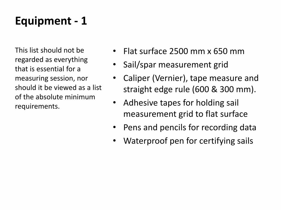
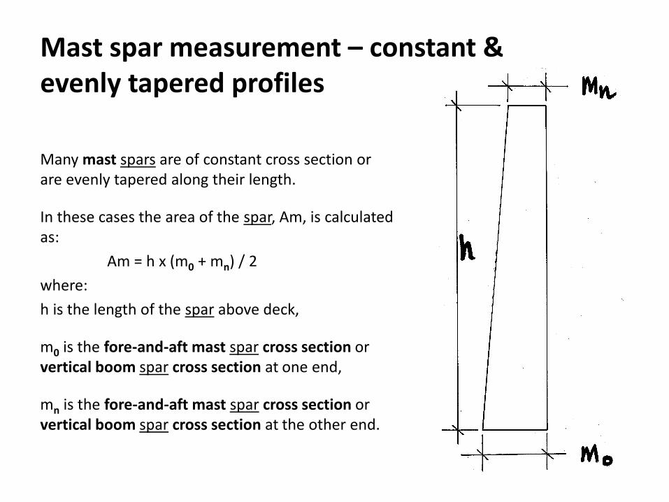
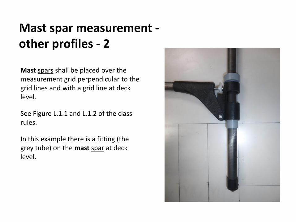
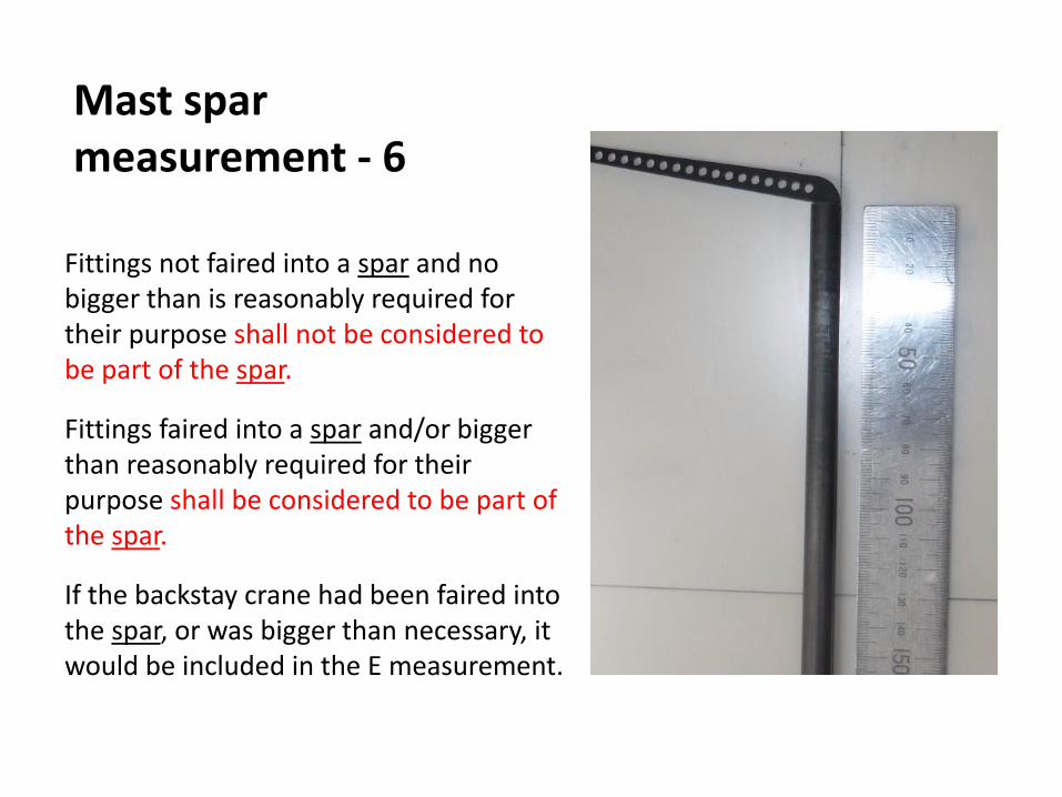
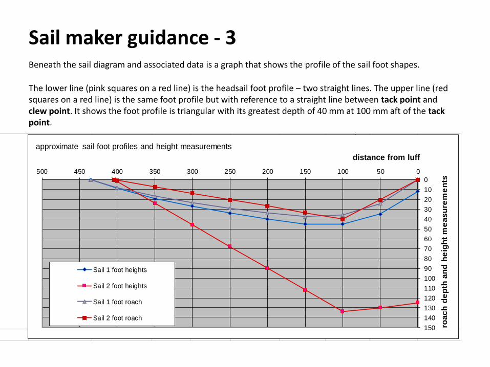

End
Valid from November 1st 2018
10 Rater Rig and Sail Measurement 2018_181028pptx