Embed Size (px)
DESCRIPTION
Lowara pumps Multistage catalogue. Complete range of lowara pump decription with specifications, technical information, dimensions and more.
Citation preview

e-SV™ Series1, 3, 5, 10, 15, 2233, 46, 66, 92, 125HIGH EFFICIENCY VERTICAL MULTISTAGE ELECTRIC PUMPSEQUIPPED WITH IE2/IE3 MOTORS COMPLYING WITH REGULATION (EC) no. 640/2009
60 Hz60 Hz60 Hz60 Hz60 Hz
CCCCCod.od.od.od.od. 191012081 R 191012081 R 191012081 R 191012081 R 191012081 Revevevevev.B Ed.06/2012.B Ed.06/2012.B Ed.06/2012.B Ed.06/2012.B Ed.06/2012

2
e-SV™ SERIESe-SV™ SERIESe-SV™ SERIESe-SV™ SERIESe-SV™ SERIESHYDRAHYDRAHYDRAHYDRAHYDRAULIC PERFORMANCE RANGE AULIC PERFORMANCE RANGE AULIC PERFORMANCE RANGE AULIC PERFORMANCE RANGE AULIC PERFORMANCE RANGE AT 60 HzT 60 HzT 60 HzT 60 HzT 60 Hz
0609
3_B
_CH
Q [m3/h]0.7 0.80.9 2 3 4 5 6 7 8 9 20 30 40 50 60 70 80 90 2001 10 100
H [m
]
3
4
56
8
20
30
40
5060
80
200
300
400
500
10
100
Q [US gpm]4 5 6 8 20 30 40 50 60 80 200 300 400 500 600 80010 100
H [f
t]
20
30
40
5060
80
200
300
400
500600
800
10
100
1000
Q [l/min]20 30 40 50 60 80 200 300 400 500 600 800 2000 3000100 1000
Q [Imp gpm]3 4 5 6 8 20 30 40 50 60 80 200 300 400 500 60010 100
1SV
3SV
5SV
10S
V
15S
V
22S
V
125S
V
33S
V
46S
V
66S
V
92S
V

3
e-SV™ series specifications ...................................................................................................................55555Characteristics of 1, 3, 5, 10, 15, 22, 33, 46, 66, 92, 125SV series ......................................................66666General characteristics ..........................................................................................................................77777Identification code ................................................................................................................................888881, 3, 5SV series and 10, 15, 22SV series ≤ 4 kW, pump cross section and main components .........101010101010, 15, 22SV series ≥ 5,5 kW, pump cross section and main components ......................................111111111133, 46, 66, 92, 125SV series, pump cross section and main components .......................................1212121212125SV series, pump cross section and main components ...............................................................1313131313Mechanical seals .............................................................................................................................1414141414Motors ............................................................................................................................................1616161616SVH series pumps with Hydrovar® control system ............................................................................2020202020Typical applications of e-SV™ pumps ..............................................................................................2222222222Hydraulic performance range e-SV™ series at 60 Hz, 2 poles ..........................................................2323232323Dimensions and weights at 60 Hz, 2 poles .....................................................................................2828282828Operating characteristics e-SV™ series at 60 Hz, 2 poles .................................................................2929292929Accessories .....................................................................................................................................5151515151Special versions ...............................................................................................................................5454545454Technical appendix ..........................................................................................................................5555555555
CONTENTSCONTENTSCONTENTSCONTENTSCONTENTS

4

5
VVVVVerticalerticalerticalerticalerticalMultistageMultistageMultistageMultistageMultistageElectric PumpsElectric PumpsElectric PumpsElectric PumpsElectric Pumps
MMMMMARKET SECTORSARKET SECTORSARKET SECTORSARKET SECTORSARKET SECTORSCIVIL, AGRICULTURAL, LIGHT INDUSTRY, WATERTREATMENT, HEATING AND AIR CONDITIONING.
MOTOR• Squirrel cage in short circuit, enclosed construction with external ventilation.• Standard supplied IE2/IE3Standard supplied IE2/IE3Standard supplied IE2/IE3Standard supplied IE2/IE3Standard supplied IE2/IE3 motors are compliant with motors are compliant with motors are compliant with motors are compliant with motors are compliant with Regulation (EC) no. 640/2009 Regulation (EC) no. 640/2009 Regulation (EC) no. 640/2009 Regulation (EC) no. 640/2009 Regulation (EC) no. 640/2009 and IEC 60034-30 and IEC 60034-30 and IEC 60034-30 and IEC 60034-30 and IEC 60034-30.• IP55 protection.• Class 155 (F) insulation.• Performances according to EN 60034-1.• Standard voltage: - Single-phase version: 220-230 V, 60 Hz. - Three-phase version 2 pole: 220 V ∆, 380 V Υ, 60 Hz up to 55 kW.
i-ALERT™i-ALERT™i-ALERT™i-ALERT™i-ALERT™Patented i-ALERT™ monitor continuouslymeasures vibration to support optimumperformance.Available as standardas standardas standardas standardas standard on pumps 7,5kW (10 HP) and above.
LIQUID END MADELIQUID END MADELIQUID END MADELIQUID END MADELIQUID END MADE ENTIREL ENTIREL ENTIREL ENTIREL ENTIRELY OFY OFY OFY OFY OF ST ST ST ST STAINLESAINLESAINLESAINLESAINLESS STEEL INS STEEL INS STEEL INS STEEL INS STEEL IN THE 1, 3, 5, 10, 15, THE 1, 3, 5, 10, 15, THE 1, 3, 5, 10, 15, THE 1, 3, 5, 10, 15, THE 1, 3, 5, 10, 15, 22 m 22 m 22 m 22 m 22 m33333/h/h/h/h/h ST ST ST ST STANDARD VERSIONANDARD VERSIONANDARD VERSIONANDARD VERSIONANDARD VERSION
STSTSTSTSTANDARDANDARDANDARDANDARDANDARD MECHANICAL SEAL MECHANICAL SEAL MECHANICAL SEAL MECHANICAL SEAL MECHANICAL SEAL CAN BE REPLACED CAN BE REPLACED CAN BE REPLACED CAN BE REPLACED CAN BE REPLACED WITHOUT REMO WITHOUT REMO WITHOUT REMO WITHOUT REMO WITHOUT REMOVINGVINGVINGVINGVING THE MOTOR FROM THE MOTOR FROM THE MOTOR FROM THE MOTOR FROM THE MOTOR FROM THE PUMP THE PUMP THE PUMP THE PUMP THE PUMP (FOR 10, 15, 22, 33, 46, (FOR 10, 15, 22, 33, 46, (FOR 10, 15, 22, 33, 46, (FOR 10, 15, 22, 33, 46, (FOR 10, 15, 22, 33, 46, 66, 92, 125SV) 66, 92, 125SV) 66, 92, 125SV) 66, 92, 125SV) 66, 92, 125SV)
STSTSTSTSTANDARD MOTORANDARD MOTORANDARD MOTORANDARD MOTORANDARD MOTOR
CAN BE USED WITHCAN BE USED WITHCAN BE USED WITHCAN BE USED WITHCAN BE USED WITH THE HYDRO THE HYDRO THE HYDRO THE HYDRO THE HYDROVVVVVARARARARAR®
CONTROL SYSTEM IN CONTROL SYSTEM IN CONTROL SYSTEM IN CONTROL SYSTEM IN CONTROL SYSTEM IN ORDER TO MANAGE ORDER TO MANAGE ORDER TO MANAGE ORDER TO MANAGE ORDER TO MANAGE THE OPERA THE OPERA THE OPERA THE OPERA THE OPERATION OFTION OFTION OFTION OFTION OF THE PUMP BASED ON THE PUMP BASED ON THE PUMP BASED ON THE PUMP BASED ON THE PUMP BASED ON THE SYSTEM THE SYSTEM THE SYSTEM THE SYSTEM THE SYSTEM CONDITIONS AND CONDITIONS AND CONDITIONS AND CONDITIONS AND CONDITIONS AND SA SA SA SA SAVE ENERGVE ENERGVE ENERGVE ENERGVE ENERGYYYYY
e-SV™ seriese-SV™ seriese-SV™ seriese-SV™ seriese-SV™ series
SPECIFICASPECIFICASPECIFICASPECIFICASPECIFICATIONSTIONSTIONSTIONSTIONSPUMPThe SV pump is a non-self primingvertical multistage pump coupled to astandard motor.The liquid end, located between theupper cover and the pump casing, isheld in place by tie rods. The pumpcasing is available with differentconfigurations and connection types.• Delivery: up to 160 m160 m160 m160 m160 m33333/h/h/h/h/h.• Head: up to 280 m280 m280 m280 m280 m.• Temperature of pumped liquid: - from -30°C to +120°C for standard version.• Maximum operating pressurepressurepressurepressurepressure: - 1, 3, 5, 10, 15, 22SV with oval flanges: 16 bar (PN16). - 1, 3, 5, 10, 15, 22SV with round flanges or Victaulic®, Clamp or DIN 11851 connections: 25 bar (PN 25). - 33, 46SV: 16, 25, 40 bar (PN 16, PN 25 or PN 40). - 66, 92, 125SV: 16 or 25 bar (PN 16 or PN 25).• Tested in compliance with ISO 9906 - Annex A.• Direction of rotation: clockwise looking at the pump from the top down (marked with an arrow on the adapter and on the coupling).
APPLICAAPPLICAAPPLICAAPPLICAAPPLICATIONSTIONSTIONSTIONSTIONS• Handling of water, free of suspended solids, in the civil, industrial and agricultural sectors.• Pressure boosting and water supply systems.• Irrigation systems.• Wash systems. • Water treatment plants. • Handling of moderately aggressive liquids, demineralised water, water and glycol, etc. • Circulation of hot and cold water for heating, cooling and conditioning systems. • Boiler feed. • Pharmaceutical industries. • Food & beverage industries.

6
CHARACTERISTICCHARACTERISTICCHARACTERISTICCHARACTERISTICCHARACTERISTICS OF 1, 3, 5, 10, 15, 22SV SERIESS OF 1, 3, 5, 10, 15, 22SV SERIESS OF 1, 3, 5, 10, 15, 22SV SERIESS OF 1, 3, 5, 10, 15, 22SV SERIESS OF 1, 3, 5, 10, 15, 22SV SERIES
• Vertical multistage centrifugal pump. All metal parts in contact with the pumped liquid are made of stainless steel.• The following versions are available: - FFFFF: round flanges, in-line delivery and suction ports, AISI 304. - TTTTT: oval flanges, in-line delivery and suction ports, AISI 304. - RRRRR: round flanges, delivery port above the suction port, with four adjustable positions, AISI 304. - NNNNN: round flanges, in-line delivery and suction ports, AISI 316. - VVVVV, PPPPP: Victaulic® couplings, in-line delivery and suction ports, AISI 316. - CCCCC: Clamp couplings (DIN 32676), in-line delivery and suction ports, AISI 316. - KKKKK: threaded couplings, (DIN 11851), in-line delivery and suction ports, AISI 316.• Reduced axial thrusts enable the use of standardstandardstandardstandardstandard motors motors motors motors motors that are easily found in the market. Standard supplied IE2/IE3 three-phaseStandard supplied IE2/IE3 three-phaseStandard supplied IE2/IE3 three-phaseStandard supplied IE2/IE3 three-phaseStandard supplied IE2/IE3 three-phase surface motors surface motors surface motors surface motors surface motors ≥ 0,75 kW are compliant0,75 kW are compliant0,75 kW are compliant0,75 kW are compliant0,75 kW are compliant with Regulation (EC) no. 640/2009 with Regulation (EC) no. 640/2009 with Regulation (EC) no. 640/2009 with Regulation (EC) no. 640/2009 with Regulation (EC) no. 640/2009.
• Mechanical seal according to EN 12756 (ex DIN 24960) and ISO 3069 for 1, 3, 5SV and 10, 15, 22SV (≤ of 4 kW) series.• Balanced mechanical sealBalanced mechanical sealBalanced mechanical sealBalanced mechanical sealBalanced mechanical seal according to EN 12756 (ex DIN 24960) and ISO 3069, which cancancancancan be replaced without removing the motorbe replaced without removing the motorbe replaced without removing the motorbe replaced without removing the motorbe replaced without removing the motor from the pumpfrom the pumpfrom the pumpfrom the pumpfrom the pump for 10, 15 and 22SV (≥ of 5,5 kW) series.• Seal housing chamber designed to prevent the accumulation of air in the critical area next to the mechanical seal.• A second plug is available for 10, 15, 22SV series.• Versions with round flanges that can be coupled to counter-flanges, according to EN 1092.• Threaded, oval counter-flanges made of stainless steel are standard supply for the T versions.• Round counter-flanges made of stainless steel are available on request for the F, R and N versions.• Easy maintenance. No special tools required for assembly or disassembly.• The pumps for FThe pumps for FThe pumps for FThe pumps for FThe pumps for F, T, T, T, T, T, R, R, R, R, R, N versions are, N versions are, N versions are, N versions are, N versions are certified for drinking water use certified for drinking water use certified for drinking water use certified for drinking water use certified for drinking water use (WRAS and AC (WRAS and AC (WRAS and AC (WRAS and AC (WRAS and ACS certified)S certified)S certified)S certified)S certified).• Standard version for temperatures ranging from -30°C to +120°C.
CHARACTERISTICCHARACTERISTICCHARACTERISTICCHARACTERISTICCHARACTERISTICS OF 33, 46, 66, 92, 125SV SERIESS OF 33, 46, 66, 92, 125SV SERIESS OF 33, 46, 66, 92, 125SV SERIESS OF 33, 46, 66, 92, 125SV SERIESS OF 33, 46, 66, 92, 125SV SERIES
• The following versions are available: - GGGGG: vertical multistage centrifugal pump with impellers, diffusers and outer sleeve made entirely of stainless steel, and with pump casing and motor adaptor made of cast iron. - NNNNN, PPPPP: version made entirely of AISI 316 stainless steel.• Innovative axial load compensation system on pumps with higher head. This ensures reduced axial thrusts and enables the use of standard motors standard motors standard motors standard motors standard motors that are easily found in the market. Standard suppliedStandard suppliedStandard suppliedStandard suppliedStandard supplied IE2/IE3 three-phase surface motors are IE2/IE3 three-phase surface motors are IE2/IE3 three-phase surface motors are IE2/IE3 three-phase surface motors are IE2/IE3 three-phase surface motors are compliant with Regulation (EC) no. 640/2009 compliant with Regulation (EC) no. 640/2009 compliant with Regulation (EC) no. 640/2009 compliant with Regulation (EC) no. 640/2009 compliant with Regulation (EC) no. 640/2009.• Balanced mechanical sealBalanced mechanical sealBalanced mechanical sealBalanced mechanical sealBalanced mechanical seal according to EN 12756 (ex DIN 24960) and ISO 3069, which cancancancancan be replaced without removing the motorbe replaced without removing the motorbe replaced without removing the motorbe replaced without removing the motorbe replaced without removing the motor
from the pumpfrom the pumpfrom the pumpfrom the pumpfrom the pump.• Seal housing chamber designed to prevent the accumulation of air in the critical area next to the mechanical seal.• The pumps for G, N versions areThe pumps for G, N versions areThe pumps for G, N versions areThe pumps for G, N versions areThe pumps for G, N versions are certified for drinking water use certified for drinking water use certified for drinking water use certified for drinking water use certified for drinking water use (WRAS and AC (WRAS and AC (WRAS and AC (WRAS and AC (WRAS and ACS certified)S certified)S certified)S certified)S certified).• Standard version for temperatures ranging from -30°C to +120°C.• Pump body fitted with couplings for installing pressure gauges on both suction and delivery flanges.• In-line ports with round flanges that can be coupled to counter-flanges, in compliance with EN 1092.• Mechanical sturdiness and easy maintenance. No special tools required for assembly or disassembly.
AAAAAVVVVVAILABLE ON REQUESTAILABLE ON REQUESTAILABLE ON REQUESTAILABLE ON REQUESTAILABLE ON REQUESTSpecial versions are available to suit many applications. For details see page 54.
Inlet pressure of the pump plus static pressure of the water within the pump cannot exceed the nominal pressure(PN). Using different motors from those provided by Lowara could limit inlet pressure.In this event please contact customer services.

7
VERSION DIAGRAMVERSION DIAGRAMVERSION DIAGRAMVERSION DIAGRAMVERSION DIAGRAM
1, 3, 5, 10, 15, 22SV VERSIONS1, 3, 5, 10, 15, 22SV VERSIONS1, 3, 5, 10, 15, 22SV VERSIONS1, 3, 5, 10, 15, 22SV VERSIONS1, 3, 5, 10, 15, 22SV VERSIONS
33, 46, 66, 92, 125SV VERSIONS33, 46, 66, 92, 125SV VERSIONS33, 46, 66, 92, 125SV VERSIONS33, 46, 66, 92, 125SV VERSIONS33, 46, 66, 92, 125SV VERSIONS
GENERAL CHARACTERISTICGENERAL CHARACTERISTICGENERAL CHARACTERISTICGENERAL CHARACTERISTICGENERAL CHARACTERISTICSSSSS2-POLE SV2-POLE SV2-POLE SV2-POLE SV2-POLE SV
- - - - - - - - - - z
Max efficiency flow (m³/h) 2 3,6 7 12,4 21,8 24,5 40 50 87 108 144
Flow range (m³/h) 0,8÷2,8 1,4÷5,2 3÷10 6÷17 10÷29 13÷34 18÷48 27÷72 36÷102 54÷144 60÷160
Maximum pressure ( bar ) 25 25 25 26 26 22 28 28 22 17 18
Motor power ( kW ) 0,37÷3 0,37÷4 0,55÷5,5 0,75÷11 1,5÷18,5 2,2÷18,5 3÷37 5.5÷45 7,5÷45 11÷45 15÷55
Max η ( % ) of pump 50 60 70 71 72 73 77 79 78 80 78
Standard temperature ( °C )
1-125sv_2p60_a_tg
-30 +120
3SV 5SV 10SV1SV 15SV 22SV 125SV33SV 46SV 66SV 92SV
- - - -
33SV 46SV 66SV 92SV 125SVG CAST IRON PUMP CASING, LIQUID END MADE OF
STAINLESS STEEL, IN-LINE ROUND FLANGES
PN16, PN25 OR PN40 DEPENDING ON NUMBER OF
STAGES AND MODEL.
N ALL AISI 316 STAINLESS STEEL, IN-LINE ROUND
FLANGES, PN16, PN25 OR PN40 DEPENDING ON NUMBER OF
STAGES AND MODEL.
P ALL AISI 316 STAINLESS STEEL.
FLANGES,IN-LINE ROUND, PN40.
• = Available. For P versions see specific catalogue. 33-125sv_2p50-en_a_tc
• • •
• •
• •
• •
TYPE
•
•
2 POLES SV
• • • •
-
1SV 3SV 5SV 10SV 15SV 22SV
F AISI 304, PN25. In-line ports, round flanges • • • • • •T AISI 304, PN16. In-line ports, oval flanges • • • • • •R AISI 304, PN25. Discharge port above suction, round flanges • • • • • •N AISI 316, PN25. In-line ports, round flanges • • • • • •V AISI 316, PN25. Victaulic® couplings • • • • • •P AISI 316, PN40. Victaulic® couplings • • • • • •C AISI 316, PN25. Clamp couplings (DIN 32676) • • • • • •K AISI 316, PN25. Threaded couplings (DIN 11851) • • • • • •
• = Available. For P versions see specific catalogue. 1-22sv_2p50-en_b_tc
TYPE2 POLES
8
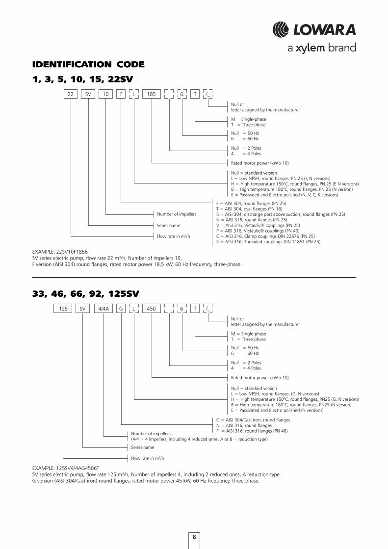
IDENTIFICAIDENTIFICAIDENTIFICAIDENTIFICAIDENTIFICATION CODETION CODETION CODETION CODETION CODE
22 L 185 T
1, 3, 5, 10, 15, 22SV1, 3, 5, 10, 15, 22SV1, 3, 5, 10, 15, 22SV1, 3, 5, 10, 15, 22SV1, 3, 5, 10, 15, 22SV
F10SV
EXAMPLE: 22SV10F1856TSV series electric pump, flow rate 22 m3/h, Number of impellers 10,F version (AISI 304) round flanges, rated motor power 18,5 kW, 60 Hz frequency, three-phase.
6
125 L 450 T
Number of impellers(4/4 = 4 impellers, including 4 reduced ones, A or B = reduction type)
33, 46, 66, 92, 125SV33, 46, 66, 92, 125SV33, 46, 66, 92, 125SV33, 46, 66, 92, 125SV33, 46, 66, 92, 125SV
GSV
EXAMPLE: 125SV4/4AG4506TSV series electric pump, flow rate 125 m3/h, Number of impellers 4, including 2 reduced ones, A reduction typeG version (AISI 304/Cast iron) round flanges, rated motor power 45 kW, 60 Hz frequency, three-phase.
64/4A
Flow rate in m3/h
Null = 2 Poles4 = 4 Poles
M = Single-phaseT = Three-phase
Series name
Number of impellers
Null = standard versionL = Low NPSH, round flanges, PN 25 (F, N versions)H = High temperature 150°C, round flanges, PN 25 (F, N versions)B = High temperature 180°C, round flanges, PN 25 (N version)E = Passivated and Electro polished (N, V, C, K versions)
Rated motor power (kW x 10)
F = AISI 304, round flanges (PN 25)T = AISI 304, oval flanges (PN 16)R = AISI 304, discharge port above suction, round flanges (PN 25)N = AISI 316, round flanges (PN 25)V = AISI 316, Victaulic® couplings (PN 25)P = AISI 316, Victaulic® couplings (PN 40)C = AISI 316, Clamp couplings DIN 32676 (PN 25)K = AISI 316, Threaded couplings DIN 11851 (PN 25)
Null = 50 Hz6 = 60 Hz
Flow rate in m3/h
Null = 2 Poles4 = 4 Poles
M = Single-phaseT = Three-phase
Series name
Null = standard versionL = Low NPSH, round flanges, (G, N versions)H = High temperature 150°C, round flanges, PN25 (G, N versions)B = High temperature 180°C, round flanges, PN25 (N version)E = Passivated and Electro polished (N versions)
Rated motor power (kW x 10)
G = AISI 304/Cast iron, round flangesN = AISI 316, round flangesP = AISI 316, round flanges (PN 40)
Null = 50 Hz6 = 60 Hz
/_
Null orletter assigned by the manufacturer
/_
Null orletter assigned by the manufacturer

9
RARARARARATING PLATING PLATING PLATING PLATING PLATETETETETE
1 - Mechanical seal material identification code 2 - Flow range 3 - Head range 4 - Minimum head 5 - Speed 6 - Frequency 7 - Maximum operating pressure 8 - Electric pump unit absorbed power
LEGENDLEGENDLEGENDLEGENDLEGEND 9 - Pump / electric pump unit type10 - O-ring material identification code11 - Electric pump unit / pump code12 - Protection class13 - Maximum liquid temperature14 - Motor nominal power15 - Rated voltage16 - Manufacturing date and serial number
1-22SV (ELECTRIC PUMP)1-22SV (ELECTRIC PUMP)1-22SV (ELECTRIC PUMP)1-22SV (ELECTRIC PUMP)1-22SV (ELECTRIC PUMP) 33-125SV (ELECTRIC PUMP)33-125SV (ELECTRIC PUMP)33-125SV (ELECTRIC PUMP)33-125SV (ELECTRIC PUMP)33-125SV (ELECTRIC PUMP)
1-22SV (PUMP)1-22SV (PUMP)1-22SV (PUMP)1-22SV (PUMP)1-22SV (PUMP) 33-125SV (PUMP)33-125SV (PUMP)33-125SV (PUMP)33-125SV (PUMP)33-125SV (PUMP)

10
1, 3, 5SV SERIES and 10, 15, 22SV SERIES 1, 3, 5SV SERIES and 10, 15, 22SV SERIES 1, 3, 5SV SERIES and 10, 15, 22SV SERIES 1, 3, 5SV SERIES and 10, 15, 22SV SERIES 1, 3, 5SV SERIES and 10, 15, 22SV SERIES ≤≤≤≤≤ 4 kW 4 kW 4 kW 4 kW 4 kWELECTRIC PUMP CROSELECTRIC PUMP CROSELECTRIC PUMP CROSELECTRIC PUMP CROSELECTRIC PUMP CROSS SECTION AND MAIN COMPONENTSS SECTION AND MAIN COMPONENTSS SECTION AND MAIN COMPONENTSS SECTION AND MAIN COMPONENTSS SECTION AND MAIN COMPONENTS
MATERIALI 1-22 SV VERSIONI F-T-R
REF. NAME MATERIAL
N. EUROPE USA
1 Pump body Stainless steel EN 10088-1-X5CrNi18-10 (1.4301) AISI 3042 Impeller Stainless steel EN 10088-1-X5CrNi18-10 (1.4301) AISI 3043 Diffuser Stainless steel EN 10088-1-X5CrNi18-10 (1.4301) AISI 3044 Outer sleeve Stainless steel EN 10088-1-X5CrNi18-10 (1.4301) AISI 3045 Shaft Stainless steel EN 10088-1-X5CrNi18-10 (1.4301) AISI 3046 Adapter Cast iron EN 1561-GJL-250 (JL1040) ASTM Class 357 Base Aluminium EN 1706-AC-AlSi11Cu2 (Fe) (AC46100) -8 Coupling Aluminium EN 1706-AC-AlSi11Cu2 (Fe) (AC46100) -9 Seal housing Stainless steel EN 10088-1-X5CrNi18-10 (1.4301) AISI 304
10 Mechanical seal Silicon carbide / Carbon / EPDM 11 Elastomers EPDM12 Coupling protection Stainless steel EN 10088-1-X5CrNi18-10 (1.4301) AISI 30413 Shaft sleeve and bushing Tungsten carbide14 Fill / drain plugs Stainless steel EN 10088-1-X5CrNi18-10 (1.4301) AISI 30415 Tie rods Galvanized steel EN 10277-3-36SMnPb14 (1.0765)16 Wear ring Technopolymer PPS
1-22sv-ftr-en_a_tm
REFERENCE STANDARDS
MATERIALI 1-22SV VERSIONI N-V-C-K
REF. NAME MATERIAL
N. EUROPE USA
1 Pump body Stainless steel EN 10088-1-X2CrNiMo17-12-2 (1.4404) AISI 316L2 Impeller Stainless steel EN 10088-1-X2CrNiMo17-12-2 (1.4404) AISI 316L3 Diffuser and upper spacer Stainless steel EN 10088-1-X2CrNiMo17-12-2 (1.4404) AISI 316L4 Outer sleeve Stainless steel EN 10088-1-X2CrNiMo17-12-2 (1.4404) AISI 316L5 Shaft Stainless steel EN 10088-1-X5CrNiMo17-12-2 (1.4401) AISI 3166 Adapter Cast iron EN 1561-GJL-250 (JL1040) ASTM Class 357 Base Aluminium EN 1706-AC-AlSi11Cu2 (Fe) (AC46100) -8 Coupling Aluminium EN 1706-AC-AlSi11Cu2 (Fe) (AC46100) -9 Seal housing Stainless steel EN 10088-1-X2CrNiMo17-12-2 (1.4404) AISI 316L
10 Mechanical seal Silicon carbide / Carbon / EPDM 11 Elastomers EPDM12 Coupling protection Stainless steel EN 10088-1-X5CrNi18-10 (1.4301) AISI 30413 Shaft sleeve and bushing Tungsten carbide14 Fill / drain plugs Stainless steel EN 10088-1-X5CrNiMo17-12-2 (1.4401) AISI 31615 Tie rods Stainless steel EN 10088-1-X17CrNi16-2 (1.4057) AISI 43116 Wear ring Technopolymer PPS
1-22sv-nvck-en_a_tm
REFERENCE STANDARDS
N, VN, VN, VN, VN, V, C, K VERSIONS, C, K VERSIONS, C, K VERSIONS, C, K VERSIONS, C, K VERSIONS
FFFFF, T, T, T, T, T, R VERSIONS, R VERSIONS, R VERSIONS, R VERSIONS, R VERSIONS

11
10, 15, 22SV SERIES 10, 15, 22SV SERIES 10, 15, 22SV SERIES 10, 15, 22SV SERIES 10, 15, 22SV SERIES ≥≥≥≥≥ 5,5 kW 5,5 kW 5,5 kW 5,5 kW 5,5 kWELECTRIC PUMP CROSELECTRIC PUMP CROSELECTRIC PUMP CROSELECTRIC PUMP CROSELECTRIC PUMP CROSS SECTION AND MAIN COMPONENTSS SECTION AND MAIN COMPONENTSS SECTION AND MAIN COMPONENTSS SECTION AND MAIN COMPONENTSS SECTION AND MAIN COMPONENTS
MATERIALI 10-22 SV VERSIONI F-T-R
REF. NAME MATERIAL
N. EUROPE USA
1 Pump body Stainless steel EN 10088-1-X5CrNi18-10 (1.4301) AISI 3042 Impeller Stainless steel EN 10088-1-X5CrNi18-10 (1.4301) AISI 3043 Diffuser Stainless steel EN 10088-1-X5CrNi18-10 (1.4301) AISI 3044 Outer sleeve Stainless steel EN 10088-1-X5CrNi18-10 (1.4301) AISI 3045 Shaft Stainless steel EN 10088-1-X5CrNi18-10 (1.4301) AISI 3046 Adapter Cast iron EN 1561-GJL-250 (JL1040) ASTM Class 357 Base Aluminium EN 1706-AC-AlSi11Cu2 (Fe) (AC46100) -8 Coupling Aluminium EN 1706-AC-AlSi11Cu2 (Fe) (AC46100) -9 Seal plate Stainless steel EN 10088-1-X5CrNi18-10 (1.4301) AISI 304
10 Mechanical seal Silicon carbide / Carbon / EPDM 11 Elastomers EPDM12 Coupling protection Stainless steel EN 10088-1-X5CrNi18-10 (1.4301) AISI 30413 Shaft sleeve and bushing Tungsten carbide14 Fill / drain plugs Stainless steel EN 10088-1-X5CrNi18-10 (1.4301) AISI 30415 Tie rods Stainless steel EN 10277-3-36SMnPb14 (1.0765)16 Wear ring Technopolymer PPS17 Seal gland Stainless steel EN 10213-4-GX5CrNi19-10 (1.4308) AISI 304
10-22sv-ftr-en_a_tm
REFERENCE STANDARDS
MATERIALI 10-22SV VERSIONI N-V-C-K
REF. NAME MATERIAL
N. EUROPE USA
1 Pump body Stainless steel EN 10088-1-X2CrNiMo17-12-2 (1.4404) AISI 316L2 Impeller Stainless steel EN 10088-1-X2CrNiMo17-12-2 (1.4404) AISI 316L3 Diffuser Stainless steel EN 10088-1-X2CrNiMo17-12-2 (1.4404) AISI 316L4 Outer sleeve Stainless steel EN 10088-1-X2CrNiMo17-12-2 (1.4404) AISI 316L5 Shaft Stainless steel EN 10088-1-X5CrNiMo17-12-2 (1.4401) AISI 3166 Adapter Cast iron EN 1561-GJL-250 (JL1040) ASTM Class 357 Base Aluminium EN 1706-AC-AlSi11Cu2 (Fe) (AC46100) -8 Coupling Aluminium EN 1706-AC-AlSi11Cu2 (Fe) (AC46100) -9 Seal plate Stainless steel EN 10088-1-X2CrNiMo17-12-2 (1.4404) AISI 316L
10 Mechanical seal Silicon carbide / Carbon / EPDM 11 Elastomers EPDM12 Coupling protection Stainless steel EN 10088-1-X5CrNi18-10 (1.4301) AISI 30413 Shaft sleeve and bushing Tungsten carbide14 Fill / drain plugs Stainless steel EN 10088-1-X5CrNiMo17-12-2 (1.4401) AISI 31615 Tie rods Stainless steel EN 10088-1-X17CrNi16-2 (1.4057) AISI 43116 Wear ring Technopolymer PPS17 Seal gland Stainless steel EN 10213-4-GX5CrNiMo19-11-2 (1.4408) AISI 316
10-22sv-nvck-en_a_tm
REFERENCE STANDARDS
N, VN, VN, VN, VN, V, C, K VERSIONS, C, K VERSIONS, C, K VERSIONS, C, K VERSIONS, C, K VERSIONS
FFFFF, T, T, T, T, T, R VERSIONS, R VERSIONS, R VERSIONS, R VERSIONS, R VERSIONS
12
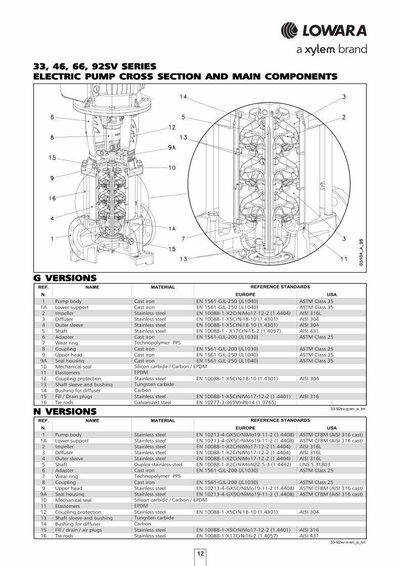
33, 46, 66, 92SV SERIES33, 46, 66, 92SV SERIES33, 46, 66, 92SV SERIES33, 46, 66, 92SV SERIES33, 46, 66, 92SV SERIESELECTRIC PUMP CROSELECTRIC PUMP CROSELECTRIC PUMP CROSELECTRIC PUMP CROSELECTRIC PUMP CROSS SECTION AND MAIN COMPONENTSS SECTION AND MAIN COMPONENTSS SECTION AND MAIN COMPONENTSS SECTION AND MAIN COMPONENTSS SECTION AND MAIN COMPONENTS
G VERSIONSG VERSIONSG VERSIONSG VERSIONSG VERSIONSMATERIALI 33-92SV VERSIONI G
REF. NAME MATERIAL
N. EUROPE USA
1 Pump body Cast iron EN 1561-GJL-250 (JL1040) ASTM Class 351A Lower support Cast iron EN 1561-GJL-250 (JL1040) ASTM Class 352 Impeller Stainless steel EN 10088-1-X2CrNiMo17-12-2 (1.4404) AISI 316L3 Diffuser Stainless steel EN 10088-1-X5CrNi18-10 (1.4301) AISI 3044 Outer sleeve Stainless steel EN 10088-1-X5CrNi18-10 (1.4301) AISI 3045 Shaft Stainless steel EN 10088-1 - X17CrNi16-2 (1.4057) AISI 4316 Adapter Cast iron EN 1561-GJL-200 (JL1030) ASTM Class 257 Wear ring8 Coupling Cast iron EN 1561-GJL-200 (JL1030) ASTM Class 259 Upper head Cast iron EN 1561-GJL-250 (JL1040) ASTM Class 35
9A Seal housing Cast iron EN 1561-GJL-250 (JL1040) ASTM Class 3510 Mechanical seal11 Elastomers12 Coupling protection Stainless steel EN 10088-1-X5CrNi18-10 (1.4301) AISI 30413 Shaft sleeve and bushing14 Bushing for diffuser15 Fill / Drain plugs Stainless steel EN 10088-1-X5CrNiMo17-12-2 (1.4401) AISI 31616 Tie rods Galvanized steel EN 10277-3-36SMnPb14 (1.0765) -
33-92sv-g-en_a_tm
Carbon
Technopolymer PPS
REFERENCE STANDARDS
Silicon carbide / Carbon / EPDM EPDM
Tungsten carbide
MATERIALI 33-92SV VERSIONI N
REF. NAME MATERIAL
N. EUROPE USA
1 Pump body Stainless steel EN 10213-4-GX5CrNiMo19-11-2 (1.4408) ASTM CF8M (AISI 316 cast)1A Lower support Stainless steel EN 10213-4-GX5CrNiMo19-11-2 (1.4408) ASTM CF8M (AISI 316 cast)2 Impeller Stainless steel EN 10088-1-X2CrNiMo17-12-2 (1.4404) AISI 316L3 Diffuser Stainless steel EN 10088-1-X2CrNiMo17-12-2 (1.4404) AISI 316L4 Outer sleeve Stainless steel EN 10088-1-X2CrNiMo17-12-2 (1.4404) AISI 316L5 Shaft Duplex stainless steel EN 10088-1-X2CrNiMoN22-5-3 (1.4462) UNS S 318036 Adapter Cast iron EN 1561-GJL-200 (JL1030) ASTM Class 257 Wear ring8 Coupling Cast iron EN 1561-GJL-200 (JL1030) ASTM Class 259 Upper head Stainless steel EN 10213-4-GX5CrNiMo19-11-2 (1.4408) ASTM CF8M (AISI 316 cast)
9A Seal housing Stainless steel EN 10213-4-GX5CrNiMo19-11-2 (1.4408) ASTM CF8M (AISI 316 cast)10 Mechanical seal11 Elastomers12 Coupling protection Stainless steel EN 10088-1-X5CrNi18-10 (1.4301) AISI 30413 Shaft sleeve and bushing14 Bushing for diffuser15 Fill / drain / air plugs Stainless steel EN 10088-1-X5CrNiMo17-12-2 (1.4401) AISI 31616 Tie rods Stainless steel EN 10088-1-X17CrNi16-2 (1.4057) AISI 431
33-92sv-n-en_a_tm
Carbon
Technopolymer PPS
REFERENCE STANDARDS
Silicon carbide / Carbon / EPDM EPDM
Tungsten carbide
N VERSIONSN VERSIONSN VERSIONSN VERSIONSN VERSIONS

13
125SV SERIES125SV SERIES125SV SERIES125SV SERIES125SV SERIESELECTRIC PUMP CROSELECTRIC PUMP CROSELECTRIC PUMP CROSELECTRIC PUMP CROSELECTRIC PUMP CROSS SECTION AND MAIN COMPONENTSS SECTION AND MAIN COMPONENTSS SECTION AND MAIN COMPONENTSS SECTION AND MAIN COMPONENTSS SECTION AND MAIN COMPONENTS
G VERSIONSG VERSIONSG VERSIONSG VERSIONSG VERSIONSMATERIALI 125 SV VERSIONI G
REF. NAME MATERIAL
N. EUROPE USA
1 Pump body Cast iron EN 1561-GJL-250 (JL1040) ASTM Class 351A Lower support Stainless steel EN 10213-GX5CrNi19-10 (1.4308) AISI 3042-3 Impeller, Diffuser Stainless steel EN 10213-GX5CrNi19-10 (1.4308) AISI 3044 Outer sleeve Stainless steel EN 10088-1-X5CrNi18-10 (1.4301) AISI 3045 Shaft Stainless steel EN 10088-1 - X17CrNi16-2 (1.4057) AISI 431
Adapter ( up to 45kW ) Cast iron EN 1561-GJL-200 (JL1030) ASTM Class 25 Adapter ( for higher powers ) Cast iron EN 1563-GJS-500-7 (JS1050) ASTM A 536 80-55-06
7 Wear ring Coupling ( up to 45kW ) Cast iron EN 1561-GJL-200 (JL1030) ASTM Class 25 Coupling ( for higher powers ) Cast iron EN 1563-GJS-500-7 (JS1050) ASTM A 536 80-55-06
9-9A Upper head, Seal housing Cast iron EN 1561-GJL-250 (JL1040) ASTM Class 3510 Mechanical seal11 Elastomers12 Coupling protection Stainless steel EN 10088-1-X5CrNi18-10 (1.4301) AISI 30413 Shaft sleeve and bushing14 Bushing for diffuser15 Fill / drain / air plugs Stainless steel EN 10088-1-X5CrNiMo17-12-2 (1.4401) AISI 31616 Tie rods Galvanized steel EN 10277-3-36SMnPb14 (1.0765) -17 Adapter ring Stainless steel EN 10213-GX5CrNi19-10 (1.4308) AISI 304
125sv-g-en_a_tm
REFERENCE STANDARDS
6
Technopolymer PPS
8
Silicon carbide / Carbon / EPDM EPDM
Tungsten carbide Carbon
MATERIALI 125SV VERSIONI N
REF. NAME MATERIAL
N. EUROPE USA
1 Pump body Stainless steel EN 10213-4-GX5CrNiMo19-11-2 (1.4408) ASTM CF8M (AISI 316) 1A Lower support Stainless steel EN 10213-4-GX5CrNiMo19-11-2 (1.4408) ASTM CF8M (AISI 316) 2-3 Impeller, Diffuser Stainless steel EN 10213-4-GX5CrNiMo19-11-2 (1.4408) ASTM CF8M (AISI 316) 4 Outer sleeve Stainless steel EN 10088-1-X2CrNiMo17-12-2 (1.4404) AISI 316L5 Shaft Duplex stainless steel EN 10088-1-X2CrNiMoN22-5-3 (1.4462) UNS S 31803
Adapter Cast iron EN 1561-GJL-200 (JL1030) ASTM Class 25 Adapter Cast iron EN 1563-GJS-500-7 (JS1050)
7 Wear ring Coupling Cast iron EN 1561-GJL-200 (JL1030) ASTM Class 25 Coupling Cast iron EN 1563-GJS-500-7 (JS1050)
9-9A Upper head, Seal housing Stainless steel EN 10213-4-GX5CrNiMo19-11-2 (1.4408) ASTM CF8M (AISI 316) 10 Mechanical seal11 Elastomers12 Coupling protection Stainless steel EN 10088-1-X5CrNi18-10 (1.4301) AISI 30413 Shaft sleeve and bushing14 Bushing for diffuser15 Fill / drain / air plugs Stainless steel EN 10088-1-X5CrNiMo17-12-2 (1.4401) AISI 31616 Tie rods Stainless steel EN 10088-1-X17CrNi16-2 (1.4057) AISI 43117 Adapter ring Stainless steel EN 10213-4-GX5CrNiMo19-11-2 (1.4408) ASTM CF8M (AISI 316)
125sv-n-en_a_tm
Silicon carbide / Carbon / EPDM EPDM
Tungsten carbide Carbon
REFERENCE STANDARDS
6
8
Technopolymer PPS
N VERSIONSN VERSIONSN VERSIONSN VERSIONSN VERSIONS

33, 46, 66, 92, 125SV33, 46, 66, 92, 125SV33, 46, 66, 92, 125SV33, 46, 66, 92, 125SV33, 46, 66, 92, 125SV
14
TENUTA MECCANICA SV MATERIALI
Q1 : Silicon Carbide E : EPDM GG : AISI 316
B : Resin impregnated carbon V V : FPM
C : Special resin impregnated carbon T T : PTFE
sv_ten-mec-en_a_tm
POSITION 1 - 2 POSITION 3 POSITION 4 - 5
e-SV™ SERIESe-SV™ SERIESe-SV™ SERIESe-SV™ SERIESe-SV™ SERIESMECHANICAL SEALS, ACCORDING TO EN 12756MECHANICAL SEALS, ACCORDING TO EN 12756MECHANICAL SEALS, ACCORDING TO EN 12756MECHANICAL SEALS, ACCORDING TO EN 12756MECHANICAL SEALS, ACCORDING TO EN 12756
LIST OF MALIST OF MALIST OF MALIST OF MALIST OF MATERIALSTERIALSTERIALSTERIALSTERIALS
PRESPRESPRESPRESPRESSURE/TEMPERASURE/TEMPERASURE/TEMPERASURE/TEMPERASURE/TEMPERATURE APPLICATURE APPLICATURE APPLICATURE APPLICATURE APPLICATION LIMITS FOR COMPLETE PUMPTION LIMITS FOR COMPLETE PUMPTION LIMITS FOR COMPLETE PUMPTION LIMITS FOR COMPLETE PUMPTION LIMITS FOR COMPLETE PUMP(APPLICABLE WITH ANY OF THE SEALS LISTED ABO(APPLICABLE WITH ANY OF THE SEALS LISTED ABO(APPLICABLE WITH ANY OF THE SEALS LISTED ABO(APPLICABLE WITH ANY OF THE SEALS LISTED ABO(APPLICABLE WITH ANY OF THE SEALS LISTED ABOVE)VE)VE)VE)VE)
TYPE OF SEALTYPE OF SEALTYPE OF SEALTYPE OF SEALTYPE OF SEAL
1, 3, 5SV 1, 3, 5SV 1, 3, 5SV 1, 3, 5SV 1, 3, 5SV10, 15, 22SV10, 15, 22SV10, 15, 22SV10, 15, 22SV10, 15, 22SV ≤≤≤≤≤ 4 kW4 kW4 kW4 kW4 kW
10, 15, 22SV10, 15, 22SV10, 15, 22SV10, 15, 22SV10, 15, 22SV ≥≥≥≥≥ 5,5 kW5,5 kW5,5 kW5,5 kW5,5 kW
TENUTA MECCANICA SV COMBINAZIONI
TEMPERATURE
1 2 3 4 5
ROTATING PART STATIONARY PART ELASTOMERS SPRINGS OTHER COMPONENTS
Q1 B E G G Q1 B E G G -30 +120
Q1 Q1 E G G Q1 Q1 E G G -30 +120
Q1 B V G G Q1 B V G G -10 +120
Q1 Q1 V G G Q1 Q1 V G G -10 +120
*Q1 C T G G Q1 C T G G 0 +120
*Q1 Q1 T G G Q1 Q1 T G G 0 +120
* Versions with anti-rotation lock pin of the fixed part. sv_tipi-ten-mec-en_b_tc
STANDARD MECHANICAL SEAL
OTHER TYPES OF AVAILABLE MECHANICAL SEAL
POSITION
( °C )TYPE
15
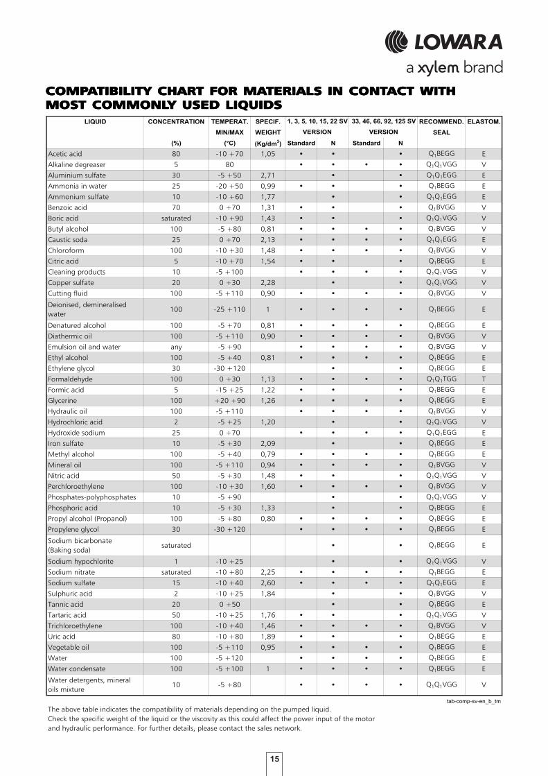
COMPCOMPCOMPCOMPCOMPAAAAATIBILITY CHART FOR MATIBILITY CHART FOR MATIBILITY CHART FOR MATIBILITY CHART FOR MATIBILITY CHART FOR MATERIALS IN CONTTERIALS IN CONTTERIALS IN CONTTERIALS IN CONTTERIALS IN CONTACT WITHACT WITHACT WITHACT WITHACT WITHMOST COMMONLMOST COMMONLMOST COMMONLMOST COMMONLMOST COMMONLY USED LIQUIDSY USED LIQUIDSY USED LIQUIDSY USED LIQUIDSY USED LIQUIDSTABELLA DI COMPATIBILITA' DEI MATERIALI A CONTATTO CON I PRINCIPALI LIQUIDI
LIQUID CONCENTRATION TEMPERAT. SPECIF. RECOMMEND. ELASTOM.
MIN/MAX WEIGHT SEAL
(%) (°C) (Kg/dm3) Standard N Standard N
Acetic acid 80 -10 +70 1,05 • • • Q1BEGG E
Alkaline degreaser 5 80 • • • • Q1Q1VGG V
Aluminium sulfate 30 -5 +50 2,71 • • Q1Q1EGG E
Ammonia in water 25 -20 +50 0,99 • • • Q1BEGG E
Ammonium sulfate 10 -10 +60 1,77 • • Q1Q1EGG E
Benzoic acid 70 0 +70 1,31 • • • Q1BVGG V
Boric acid saturated -10 +90 1,43 • • • Q1Q1VGG V
Butyl alcohol 100 -5 +80 0,81 • • • • Q1BVGG V
Caustic soda 25 0 +70 2,13 • • • • Q1Q1EGG E
Chloroform 100 -10 +30 1,48 • • • • Q1BVGG V
Citric acid 5 -10 +70 1,54 • • • Q1BEGG E
Cleaning products 10 -5 +100 • • • • Q1Q1VGG V
Copper sulfate 20 0 +30 2,28 • • Q1Q1VGG V
Cutting fluid 100 -5 +110 0,90 • • • • Q1BVGG V
Deionised, demineralised
water100 -25 +110 1 • • • • Q1BEGG E
Denatured alcohol 100 -5 +70 0,81 • • • • Q1BEGG E
Diathermic oil 100 -5 +110 0,90 • • • • Q1BVGG V
Emulsion oil and water any -5 +90 • • • • Q1BVGG V
Ethyl alcohol 100 -5 +40 0,81 • • • • Q1BEGG E
Ethylene glycol 30 -30 +120 • • Q1BEGG E
Formaldehyde 100 0 +30 1,13 • • • • Q1Q1TGG T
Formic acid 5 -15 +25 1,22 • • • Q1BEGG E
Glycerine 100 +20 +90 1,26 • • • • Q1BEGG E
Hydraulic oil 100 -5 +110 • • • • Q1BVGG V
Hydrochloric acid 2 -5 +25 1,20 • • Q1Q1VGG V
Hydroxide sodium 25 0 +70 • • • • Q1Q1EGG E
Iron sulfate 10 -5 +30 2,09 • • Q1BEGG E
Methyl alcohol 100 -5 +40 0,79 • • • • Q1BEGG E
Mineral oil 100 -5 +110 0,94 • • • • Q1BVGG V
Nitric acid 50 -5 +30 1,48 • • • Q1Q1VGG V
Perchloroethylene 100 -10 +30 1,60 • • • • Q1BVGG V
Phosphates-polyphosphates 10 -5 +90 • • Q1Q1VGG V
Phosphoric acid 10 -5 +30 1,33 • • Q1BEGG E
Propyl alcohol (Propanol) 100 -5 +80 0,80 • • • • Q1BEGG E
Propylene glycol 30 -30 +120 • • • • Q1BEGG E
Sodium bicarbonate
(Baking soda)saturated • • Q1BEGG E
Sodium hypochlorite 1 -10 +25 • • Q1Q1VGG V
Sodium nitrate saturated -10 +80 2,25 • • • • Q1BEGG E
Sodium sulfate 15 -10 +40 2,60 • • • • Q1Q1EGG E
Sulphuric acid 2 -10 +25 1,84 • • Q1BVGG V
Tannic acid 20 0 +50 • • Q1BEGG E
Tartaric acid 50 -10 +25 1,76 • • • Q1Q1VGG V
Trichloroethylene 100 -10 +40 1,46 • • • • Q1BVGG V
Uric acid 80 -10 +80 1,89 • • • Q1BEGG E
Vegetable oil 100 -5 +110 0,95 • • • • Q1BEGG E
Water 100 -5 +120 • • • • Q1BEGG E
Water condensate 100 -5 +100 1 • • • • Q1BEGG E
Water detergents, mineral
oils mixture10 -5 +80 • • • • Q1Q1VGG V
tab-comp-sv-en_b_tm
The above table indicates the compatibility of materials depending on the pumped liquid.
Check the specific weight of the liquid or the viscosity as this could affect the power input of the motor
and hydraulic performance. For further details, please contact the sales network.
VERSION VERSION
1, 3, 5, 10, 15, 22 SV 33, 46, 66, 92, 125 SV

16
e-SV™ SERIESe-SV™ SERIESe-SV™ SERIESe-SV™ SERIESe-SV™ SERIESMOTORSMOTORSMOTORSMOTORSMOTORS
SINGLE-PHASE MOTORS ASINGLE-PHASE MOTORS ASINGLE-PHASE MOTORS ASINGLE-PHASE MOTORS ASINGLE-PHASE MOTORS AT 60 Hz, 2 POLEST 60 Hz, 2 POLEST 60 Hz, 2 POLEST 60 Hz, 2 POLEST 60 Hz, 2 POLESMOTORI MONOFASE PER SERIE 1-22 SV 60 Hz, 2 poli
INPUT
CURRENT
PN In (A) Tn
kW 220-230 V µF V min-1 ls / ln η % cosϕ Nm Ts/Tn Tm/Tn
0,4 SM71RB14/1046 71R 2,86-2,94 14 450 3385 3,80 67,5 0,94 1,13 0,73 2,04
0,55 SM71B14/1056 71 3,68-3,62 16 450 3400 4,28 70,2 0,97 1,54 0,66 2,11
0,75 SM80RB14/1076 80R 4,98-4,88 20 450 3380 3,90 69,8 0,98 2,12 0,64 1,91
1,1 SM80B14/1116 80 6,94-6,89 30 450 3435 4,54 74,2 0,97 3,06 0,62 2,03
1,5 SM90RB14/1156 90R 9,28-9,35 40 450 3455 4,91 76,3 0,96 4,14 0,49 2,19
2,2 PLM90B14/1226 90 12,3-11,7 60 450 3455 4,99 83,4 0,98 6,08 0,54 2,06
* R =Reduced size of motor casing as compared to shaft extension and flange. 1-22sv-motm-2p60_en_d_te
IEC
SIZ
E*
MOTOR TYPE
V1
8/B
14
DATA FOR 220 V 60 Hz VOLTAGECAPACITOR
Co
nstr
ucti
on
Desig
n
• Standard supplied IE2/IE3 three-phaseStandard supplied IE2/IE3 three-phaseStandard supplied IE2/IE3 three-phaseStandard supplied IE2/IE3 three-phaseStandard supplied IE2/IE3 three-phase surface motors surface motors surface motors surface motors surface motors ≥ 0,75 kW are compliant0,75 kW are compliant0,75 kW are compliant0,75 kW are compliant0,75 kW are compliant with Regulation (EC) no. 640/2009 and with Regulation (EC) no. 640/2009 and with Regulation (EC) no. 640/2009 and with Regulation (EC) no. 640/2009 and with Regulation (EC) no. 640/2009 and IEC 60034-30 IEC 60034-30 IEC 60034-30 IEC 60034-30 IEC 60034-30.• Short-circuit squirrel-cage motor (TEFC), enclosed construction with external ventilation.• IP55 protection.• Class 155 (F) insulation.• Performance according to EN 60034-1.• Standard voltage.• Cable gland with standard passage dimensions according to EN 50262 (metric thread).
• Single-phase Single-phase Single-phase Single-phase Single-phase version: 220-230 V 60 Hz with built-in automatic reset overload protection up to 1,5 kW. For higher powers the protection must be provided by the user.• Three-phase Three-phase Three-phase Three-phase Three-phase version 2 pole: 220 V ∆, 380 V Υ, 60 Hz up to 55 kW. Overload protection to be provided by the user.
Standard supplied SV electric pumps are equipped with Standard motors.

17
e-SV™ SERIESe-SV™ SERIESe-SV™ SERIESe-SV™ SERIESe-SV™ SERIESTHREE-PHASE MOTORS ATHREE-PHASE MOTORS ATHREE-PHASE MOTORS ATHREE-PHASE MOTORS ATHREE-PHASE MOTORS AT 60 Hz, 2 POLES (up to 22 kW)T 60 Hz, 2 POLES (up to 22 kW)T 60 Hz, 2 POLES (up to 22 kW)T 60 Hz, 2 POLES (up to 22 kW)T 60 Hz, 2 POLES (up to 22 kW)MOTORI TRIFASE PER SERIE 1-125SV Ie2 60 Hz, 2 poli (fino a 22 kW)
PN
kW 4/4 3/4 2/4 4/4 3/4 2/4 4/4 3/4 2/4 4/4 3/4 2/4
0,4 - - - - - - - - - - - - -0,55 - - - - - - - - - - - - -0,75 83,4 82,4 79,0 83,4 82,4 79,0 83,4 82,4 79,0 83,4 82,4 79,01,1 85,6 85,0 82,1 85,6 85,0 82,1 85,6 85,0 82,1 85,6 85,0 82,11,5 87,2 87,0 84,6 87,2 87,0 84,6 87,2 87,0 84,6 87,2 87,0 84,62,2 85,5 85,5 84,5 85,5 85,5 84,5 85,5 85,5 84,5 85,5 85,5 84,53 87,8 88,0 86,0 87,8 88,0 86,0 87,8 88,0 86,0 87,8 88,0 86,04 87,5 87,5 86,8 87,5 87,5 86,8 87,5 87,5 86,8 87,5 87,5 86,8
5,5 88,5 88,5 88,5 88,5 88,5 88,5 88,5 88,5 88,5 88,5 88,5 88,57,5 89,5 89,5 88,5 89,5 89,5 88,5 89,5 89,5 88,5 89,5 89,5 88,511 90,2 90,2 89,7 90,2 90,2 89,7 90,2 90,2 89,7 90,2 90,2 89,715 90,2 90,2 90,2 90,2 90,2 90,2 90,2 90,2 90,2 90,2 90,2 90,2
18,5 91,0 91,0 91,0 91,0 91,0 91,0 91,0 91,0 91,0 91,0 91,0 91,022 91,0 91,0 91,0 91,0 91,0 91,0 91,0 91,0 91,0 91,0 91,0 91,0
PN fN TN
kW Hz cosϕ ls / lN Nm Ts/TN Tm/Tn
0,4 71R 0,81 4,76 1,16 3,48 2,150,55 71 0,84 5,83 1,55 3,09 2,770,75 80 0,79 8,25 2,05 3,80 4,021,1 80 0,80 9,11 3,01 4,15 4,291,5 90R 0,82 9,79 4,10 4,36 4,372,2 90 0,83 9,59 6,00 3,80 4,023 100R 0,84 9,12 8,22 3,52 3,654 112R 0,87 10,0 10,87 2,82 4,58
5,5 132R 0,89 11,4 14,97 4,28 5,807,5 132 0,88 9,83 20,29 3,21 4,6811 160R 0,88 10,2 29,81 3,43 4,5115 160 0,91 8,60 40,41 2,24 3,84
18,5 160 0,89 9,97 49,72 2,78 4,5922 180R 0,91 9,64 59,15 2,76 4,25
0
Altitude T. amb ATEX
PN 220 V 230 V 380 V 400 V 380 V 400 V 660 V 690 V above sea min/max
kW Level (m) °C
0,4 1,96 1,89 1,13 1,09 - - - -0,55 2,37 2,30 1,37 1,33 - - - -0,75 3,03 3,01 1,75 1,74 1,75 1,74 1,01 1,001,1 4,24 4,24 2,45 2,45 2,44 2,43 1,41 1,401,5 5,58 5,53 3,22 3,19 3,23 3,22 1,86 1,862,2 8,14 8,12 4,70 4,69 4,69 4,68 2,71 2,703 10,7 10,5 6,19 6,06 6,20 6,11 3,58 3,534 13,5 13,5 7,82 7,77 7,84 7,77 4,52 4,49
5,5 18,2 18,1 10,5 10,4 10,5 10,4 6,07 6,027,5 25,2 24,7 14,6 14,3 14,6 14,1 8,40 8,1611 36,1 35,2 20,8 20,3 21,1 20,7 12,2 12,015 47,1 45,6 27,2 26,4 27,3 26,3 15,8 15,2
18,5 59,2 58,2 34,2 33,6 34,3 33,6 19,8 19,422 69,1 67,4 39,9 38,9 39,8 38,2 23,0 22,0
* R =Reduced size of motor casing as compared to shaft extension and flange. sv-ie2-mott22-2p60_c_te
** Operating conditions to be referred to motor only. About electric pump, refer to limits in user’s manual.
By
June
20
11
V1
8/B
14
V1
/B5
2 60
Data for 380 V / 60 Hz
3
2
10
00
-15 / 4
0
No
IN (A) min-1
3545 ÷ 3550
3280 ÷ 3335
3490 ÷ 3505
3550 ÷ 3555
3380 ÷ 3415
∆ Y
Voltage UN
V
SM080B14/311PESM090RB14/315PEPLM090B14/322
IEC
SIZ
E*
SM071RB14/304SM071B14/305SM080B14/307PE
Manufacturer
Model
IE
Y
Operating conditions **
Co
nstr
ucti
on
Desig
n
Y 660 V Year
of
co
nstr
ucti
on
%
∆ 220 V
PLM132RB5/355
∆ 230 V
3490 ÷ 3500
3510 ÷ 3520
∆ 380 V
Y 380 V
∆ 400 V
Y 400 V
Ob
serv
e th
e re
gula
tions
and
cod
es loca
lly
in f
orc
e re
gard
ing
sort
ed w
ast
e d
isp
osa
l.
3545 ÷ 3555
3525 ÷ 35353520 ÷ 3540
PLM132B5/375
Efficiency ηN
Y 690 V
3505 ÷ 3515
N. of
Poles
∆
3485 ÷ 35053495 ÷ 3505
nN
3480 ÷ 3495
Lowara srl UnipersonaleReg. No. 341820260
Montecchio Maggiore Vicenza - Italia
PLM180RB5/3220
PLM160RB5/3110PLM160B5/3150PLM160B5/3185
PLM100RB14/330PLM112RB14/340

18
e-SV™ SERIESe-SV™ SERIESe-SV™ SERIESe-SV™ SERIESe-SV™ SERIESTHREE-PHASE MOTORS ATHREE-PHASE MOTORS ATHREE-PHASE MOTORS ATHREE-PHASE MOTORS ATHREE-PHASE MOTORS AT 60 Hz, 2 POLES (from 30 to 55 kW)T 60 Hz, 2 POLES (from 30 to 55 kW)T 60 Hz, 2 POLES (from 30 to 55 kW)T 60 Hz, 2 POLES (from 30 to 55 kW)T 60 Hz, 2 POLES (from 30 to 55 kW)MOTORI WEG 60 Hz, 2 poli
PN
kW
30374555
PN fN TN
kW Hz cosϕ ls / lN Nm Ts/TN Tm/Tn
30 200 0,86 6,40 80,65 2,10 2,4037 200 0,86 7,20 98,98 2,40 2,6045 225 0,89 7,80 120,5 2,20 2,9055 250 0,89 7,70 147,0 2,20 2,80
Altitude T. amb ATEX
PN above sea min/max
kW Level (m) °C
30374555
** Operating conditions to be referred to motor only. About electric pump, refer to limits in user’s manual. sv-ie2-mott55-2p60_a_te
Note: Observe the regulations and codes locally in force regarding sorted waste disposal.
Voltage UN
V
∆ Y
92,493,593,5
2
Co
nstr
ucti
on
Desig
n
92,4
N. of
Poles
92,491,893,0
93,5
Year
of
co
nstr
ucti
on
%
92,8
92,4
IE
91,5
Efficiency ηN
2
No
By
Jun
e
2011
min-1
See
note
.
10
00
Operating conditions **
3560
-15 / 4
0
Data for 380 V / 60 Hz
Manufacturer
35503555
3560
Model
60
70,7
IN (A)
99,0 57,3
nN
∆ 220 V
Y 380 V
4/4 3/4 2/4
92,0
W22 200L2-B5 30kW
220 V
IEC
SIZ
E
380 V
100,0142,0122,0
173,082,2
WEG Equipamentos Eletricos S.A.Reg. No. 07.175.725/0010-50
Jaragua do Sul - SC (Brazil)
V1/B
5 W22 200L2-B5 37kW W22 225S/M2-B5 45kW W22 250S/M2-B5 55kW
The table show the mean sound pressure (Lp) measuredas per Curve A (Standard ISO 1680).Noise values were measured with the 60 Hz motorrunning idle with a tolerance of 3 dB (A).
MOTOR NOISE 2 POLES 60 HzMOTOR NOISE 2 POLES 60 HzMOTOR NOISE 2 POLES 60 HzMOTOR NOISE 2 POLES 60 HzMOTOR NOISE 2 POLES 60 Hz
RUMOROSITA' MOTORI SV 2-POLI 60Hz
POWER MOTOR TYPE
kW IEC SIZE*
0,37 71R
0,55 71
0,75 80-80R
1,1 80
1,5 90-90R
2,2 90
3 100R
4 112R
5,5 132R
7,5 132
11 160R
15 160
18,5 160
22 180R
30 200
37 200
45 225
55 250
*R = Reduced motor casing size with respect 1-125sv_mott_2p60_c_tr
to shaft extension and related flange.
<70
<70
76
74
79
74
<70
<70
<70
<70
<70
<70
79
77
74
75
73
<70
NOISE
LpA
dB

19
AAAAAVVVVVAILABLE VAILABLE VAILABLE VAILABLE VAILABLE VOLOLOLOLOLTTTTTAGESAGESAGESAGESAGESMOTORS FOR e-SV™ SERIES (up to 22 kW)MOTORS FOR e-SV™ SERIES (up to 22 kW)MOTORS FOR e-SV™ SERIES (up to 22 kW)MOTORS FOR e-SV™ SERIES (up to 22 kW)MOTORS FOR e-SV™ SERIES (up to 22 kW)
MOTORS FOR e-SV™ SERIES (MOTORS FOR e-SV™ SERIES (MOTORS FOR e-SV™ SERIES (MOTORS FOR e-SV™ SERIES (MOTORS FOR e-SV™ SERIES (≥≥≥≥≥ 30 kW) 30 kW) 30 kW) 30 kW) 30 kW)
IEC
SIZ
E
1 x
220-2
40
1 x
100
1 x
110-1
20
1 x
220-2
30
1 x
100
1x
110-1
15
1 x
120-1
27
1 x
200-2
10
3 x
220-2
30-2
40/3
80-4
00-4
15
3 x
380-4
00-4
15/6
60-6
90
3 x
200-2
08/3
46-3
60
3 x
255-2
65/4
40-4
60
3 x
290-3
00/5
00-5
25
3 x
440-4
60/-
3 x
500-5
25/-
3 x
220-2
30/3
80-4
00
3 x
255-2
65-2
77/4
40-4
60-4
80
3 x
380-4
00/6
60-6
90
3 x
440-4
60-4
80/-
3 x
110-1
15/1
90-2
00
3 x
200-2
08/3
46-3
60
3 x
330-3
46/5
75-6
00
3 x
575/-
3 x
230/4
00 5
0 H
z
3 x
265/4
60 6
0 H
z
3 x
400/6
90 5
0 H
z
3 x
460/-
60 H
z
0,4 63 s o o s - o - - 0,37 s o o o o o o s o o o o o o o o o
0,55 71 s o o s o o o o 0,55 s o o o o o o s o o o o o o o o o
0,75 71 s o o s o o o o 0,75 s o o o o o o s o o o o o o o o o
1,1 80 s - o s - o - o 1,1 s o o o o o o s o o o o o o o o o
1,5 80 s - - s - o - o 1,5 s o o o o o o s o o o o o o o o o
2,2 90 s - - s - - - - 2,2 s o o o o o o s o o o o o o o o o
3 s o o o o o o s o o o o o o o o o
4 o s o o o o o s o o o o o o o o o
5,5 o s o o o o o s o o o o o o o o o
7,5 o s o o o o o s o o o o o o o o o
11 o s o o o o o s o o o o o o o o o
15 o s o o o o o s o o o o o o o o o
18,5 o s o o o o o s o o o o o o o o o
22 o s o o o o o s o o o o o o o o o
s = Standard voltage o = Optional voltage - = Not available sv-volt-lowa-en_a_te
THREE-PHASE - 2 POLES
PN
kW
SINGLE-PHASE
50 Hz 60 Hz
PN
kW
50/60 Hz50 Hz 60 Hz
3 x
220-2
30-2
40/3
80-4
00-4
15
3 x
380-4
00-4
15/6
60-6
90
3 x
11
0/1
90
3 x
200-2
08/3
46-3
60
3 x
255-2
65/4
40-4
60
3 x
290-3
00/5
00-5
25
3 x
440-4
60/-
3 x
500-5
25/-
3 x
23
0/3
80
3 x
380-4
00/6
60-6
90
3 x
440-4
80/-
3 x
110-1
15/1
90-2
00
3 x
200-2
08/3
46-3
60
3 x
255-2
65-2
77/4
40-4
60-4
80
3 x
330-3
46/5
75-6
00
3 x
575/-
3 x
230/4
00 5
0 H
z
3 x
265/4
60 6
0 H
z
3 x
400/6
90 5
0 H
z
3 x
460/-
60 H
z
30 o s o o o o o o s o o o o o o o o o
37 o s o o o o o o s o o o o o o o o o
45 o s o o o o o o s o o o o o o o o o
55 o s o o o o o o s o o o o o o o o o
s = Standard voltage o = Optional voltage - = Not available sv-volt-weg-en_b_te
PN
kW
50 Hz 60 Hz 50/60 Hz
THREE-PHASE - 2 POLES

20
SVH SERIES ELECTRIC PUMPS WITH HYDROSVH SERIES ELECTRIC PUMPS WITH HYDROSVH SERIES ELECTRIC PUMPS WITH HYDROSVH SERIES ELECTRIC PUMPS WITH HYDROSVH SERIES ELECTRIC PUMPS WITH HYDROVVVVVARARARARAR® CONTROLCONTROLCONTROLCONTROLCONTROLSYSTEMSYSTEMSYSTEMSYSTEMSYSTEMThe Lowara SV electric pumps are available in the SVHversion, i.e. coupled to Hydrovar®, the microprocessorbased control unit designed to manage the performanceof the pump based on the conditions and requirements ofthe system. The basic SV electric pump is thustransformed into a complete pumping system suitable fora number of applications, including:••••• Variable speed pressure boosting (constant pressure is maintained in industrial, civil and agricultural applications).••••• Water filtration and treatment (constant flow is maintained based on flow resistance).••••• Air conditioning and heating (constant differential pressure is maintained in a closed circuit).
••••• No special pumps or motorsNo special pumps or motorsNo special pumps or motorsNo special pumps or motorsNo special pumps or motors: HYDROVAR©
is mounted directly onto a standard three-phase TEFC motor with class F insulation up to 22 kW power. A wall-mounted version is available for higher powers, up to 45 kW.
••••• No extra pressure sensorsNo extra pressure sensorsNo extra pressure sensorsNo extra pressure sensorsNo extra pressure sensors: HYDROVAR© is equipped with a pressure transmitter or differential pressure transmitter, depending on the applications.
••••• No separate microprocessorsNo separate microprocessorsNo separate microprocessorsNo separate microprocessorsNo separate microprocessors: In multiple-pump systems the microprocessor regulates the sequential operation of the pumps or motors. Since HYDROVAR© features a built-in microprocessor, no other control devices are required.
••••• No separate control panels or convertersNo separate control panels or convertersNo separate control panels or convertersNo separate control panels or convertersNo separate control panels or converters: HYDROVAR© performs all the functions of a pump control panel, incorporating protections against overload, short circuit, high temperature, etc. The only external device required is a fuse on the power supply line. Will depend upon any local electrical installation regulations.
••••• No by-pass lines or safety systemsNo by-pass lines or safety systemsNo by-pass lines or safety systemsNo by-pass lines or safety systemsNo by-pass lines or safety systems: With HYDROVAR© the pump switches off immediately when demand is zero or exceeds the maximum capacity of the pump. This way there is no need to install additional safety devices.
••••• No large diaphragm tanks are requiredNo large diaphragm tanks are requiredNo large diaphragm tanks are requiredNo large diaphragm tanks are requiredNo large diaphragm tanks are required: Without a large pressure tank on the discharge side of the pump, a constant speed pump running at maximum power will be constantly switching on and off in order to satisfy system demands.
With the HYDROVAR© system the speed of each pump varies in order to maintain a constant pressure or flow. A small tank is sufficient to maintain system pressure and to ensure immediate shut off at zero demand, therefore there is no need to install a large tank. Where local regulations allow it, the HYDROVAR©
systems can be connected directly to the water supply line. The pump’s operation at the correct speed The pump’s operation at the correct speed The pump’s operation at the correct speed The pump’s operation at the correct speed The pump’s operation at the correct speed based on system requirements enables based on system requirements enables based on system requirements enables based on system requirements enables based on system requirements enables energy consumption to be substantially energy consumption to be substantially energy consumption to be substantially energy consumption to be substantially energy consumption to be substantially reduced. reduced. reduced. reduced. reduced.
••••• Anti-condensation heaterAnti-condensation heaterAnti-condensation heaterAnti-condensation heaterAnti-condensation heater All the units are equipped with anti-condensation heaters that switch on when the pump is in standby mode to prevent condensation inside the unit.

21
OPERAOPERAOPERAOPERAOPERATING PRINCIPLETING PRINCIPLETING PRINCIPLETING PRINCIPLETING PRINCIPLE
The basic function of the HYDROVAR® device is tocontrol the pump to meet the system demands.
HYDROHYDROHYDROHYDROHYDROVVVVVARARARARAR®®®®® performs these functions by performs these functions by performs these functions by performs these functions by performs these functions by:1) Measuring the system pressure or flow via a transmitter mounted on the pump’s delivery side.2) Calculating the motor speed to maintain the correct flow or pressure.3) Sending out a signal to the pump to start the motor, increase speed, decrease speed or stop.4) In the case of multiple pump installations, HYDROVAR®
will automatically provide for the cyclic changeover of the pump’s starting sequence.
In addition to these basic functions, HYDROVAR® can dothings only by the most advanced computerised controlsystems, such as:••••• Stop the pump(s) at zero demand.••••• Stop the pump(s) in case of water failure on the suction side (protection against dry running).••••• Stop the pump if the required delivery exceeds the pump’s capacity (protection against cavitation caused by excessive demand), or automatically switch on the next pump in a multiple series.••••• Protect the pump and motor from overvoltage, undervoltage, overload and earth fault.••••• Vary the pump speed acceleration and deceleration time.••••• Compensate for increased flow resistance at high flow rates.••••• Conduct automatic test starts at set intervals.••••• Monitor the converter and motor operating hours.••••• Display all functions on an LCD in different languages (Italian, English, French, German, Spanish, Portuguese, Dutch).••••• Send a signal to a remote control system which is proportional to the pressure and frequency.••••• Communicate with another HYDROVAR® or control system via an RS 485 interface.
TYPICAL EXAMPLE OF ENERGTYPICAL EXAMPLE OF ENERGTYPICAL EXAMPLE OF ENERGTYPICAL EXAMPLE OF ENERGTYPICAL EXAMPLE OF ENERGY SAY SAY SAY SAY SAVINGSVINGSVINGSVINGSVINGSSystem: 22SV07F75T vertical multistage electric pump with 7,5 kW motor equipped with HYDROVAR®, 70 m head.19 hour/day operation.Application: maintaining a constant pressure as the flow rate varies.
Control for constant pressure
Control to match a system curve
Control for constant flow
Control according to an external signal
TABELLA RISPARMIO ENERGETICO
FLOW POWER OPERATING TOTAL
CONSTANT SPEED VARIABLE SPEED SAVED TIME ENERGY
PUMP PUMP SAVINGS
m3/h kW kW kW (hours) kWh
24 7,4 7,4 0,0 876 - 21 6,9 6,1 0,8 876 701 18 6,5 5,0 1,5 1752 2.628 14 5,6 3,8 1,8 1752 3.154 10 5,1 2,8 2,3 1752 4.030
10.512
sv-hydr-en_a_te
YEARLY ENERGY SAVINGS (kWh)
ABSORBED POWER

22
TYPICAL APPLICATYPICAL APPLICATYPICAL APPLICATYPICAL APPLICATYPICAL APPLICATIONS OF e-SV™ SERIES ELECTRIC PUMPSTIONS OF e-SV™ SERIES ELECTRIC PUMPSTIONS OF e-SV™ SERIES ELECTRIC PUMPSTIONS OF e-SV™ SERIES ELECTRIC PUMPSTIONS OF e-SV™ SERIES ELECTRIC PUMPS
WAWAWAWAWATER SUPPLTER SUPPLTER SUPPLTER SUPPLTER SUPPLY AND PRESY AND PRESY AND PRESY AND PRESY AND PRESSURESURESURESURESUREBOOSTINGBOOSTINGBOOSTINGBOOSTINGBOOSTING• Pressure boosting in building, hotel, residential complexes.• Pressure booster stations, supply of water networks.• Booster packages.
WAWAWAWAWATER TREATER TREATER TREATER TREATER TREATMENTTMENTTMENTTMENTTMENT• Ultrafiltration systems.• Reverse osmosis systems.• Water softeners and de-mineralization.• Distillation systems.• Filtration.
LIGHT INDUSTRYLIGHT INDUSTRYLIGHT INDUSTRYLIGHT INDUSTRYLIGHT INDUSTRY• Washing and cleaning plants (washing and degreasing of mechanical parts, car and truck wash tunnels, washing of electronic industry circuits).• Commercial washers.• Firefighting system pumps.
PHARMACEUTICAL ANDPHARMACEUTICAL ANDPHARMACEUTICAL ANDPHARMACEUTICAL ANDPHARMACEUTICAL ANDFOOD & BEVERAGE INDUSTRIESFOOD & BEVERAGE INDUSTRIESFOOD & BEVERAGE INDUSTRIESFOOD & BEVERAGE INDUSTRIESFOOD & BEVERAGE INDUSTRIES• Production plant where specific sanitary standards are required.
IRRIGAIRRIGAIRRIGAIRRIGAIRRIGATION AND AGRICULTION AND AGRICULTION AND AGRICULTION AND AGRICULTION AND AGRICULTURETURETURETURETURE• Greenhouses.• Humidifiers.• Sprinkler irrigation.
HEAHEAHEAHEAHEATING, VENTILATING, VENTILATING, VENTILATING, VENTILATING, VENTILATION AND AIRTION AND AIRTION AND AIRTION AND AIRTION AND AIRCONDITIONING (HVCONDITIONING (HVCONDITIONING (HVCONDITIONING (HVCONDITIONING (HVAC)AC)AC)AC)AC)• Cooling towers and systems.• Temperature control systems.• Refrigerators.• Induction heating.• Heat exchangers.• Boilers, water recirculation and heating.

23
e-SV™ SERIESe-SV™ SERIESe-SV™ SERIESe-SV™ SERIESe-SV™ SERIESHYDRAHYDRAHYDRAHYDRAHYDRAULIC PERFORMANCE RANGE AULIC PERFORMANCE RANGE AULIC PERFORMANCE RANGE AULIC PERFORMANCE RANGE AULIC PERFORMANCE RANGE AT 60 Hz, 2 POLEST 60 Hz, 2 POLEST 60 Hz, 2 POLEST 60 Hz, 2 POLEST 60 Hz, 2 POLES
1 10 100
η [%
]
20
40
60
80
100
100 1000
H [m
]
0
20
40
60
80
100
120
140
160
180
200
220
240
260
280
30010 100
H [f
t]
0
100
200
300
400
500
600
700
800
900
10 100
0608
2_B
_CH
ISO 9906 - Annex A
Q [US gpm]
Q [Imp gpm]
Q [l/min]
Q [m3/h]
e-SV™ ∼ 3500 [rpm]
1SV
125SV15SV10SV5SV
3SV22SV
1SV
3SV
5SV
10S
V
15S
V
125S
V
22S
V
33S
V
46S
V
66S
V
92S
V
33SV 46SV 66SV 92SV

24
1, 3, 5SV SERIES1, 3, 5SV SERIES1, 3, 5SV SERIES1, 3, 5SV SERIES1, 3, 5SV SERIESHYDRAHYDRAHYDRAHYDRAHYDRAULIC PERFORMANCE TULIC PERFORMANCE TULIC PERFORMANCE TULIC PERFORMANCE TULIC PERFORMANCE TABLE AABLE AABLE AABLE AABLE AT 60 Hz, 2 POLEST 60 Hz, 2 POLEST 60 Hz, 2 POLEST 60 Hz, 2 POLEST 60 Hz, 2 POLESTABELLA DI PRESTAZIONI IDRAULICHE SERIE 1SV 3SV 5SV 2p 60 Hz
PUMP
TYPE l/min 0l/min 0 13,3413,34 2020 23,423,4 3030 3535 46,646,6 5050 6060 7070 86,686,6 100100 120120 166,67166,67
m3/h 0/h 0 0,80,8 1,21,2 1,41,4 1,81,8 2,12,1 2,82,8 3,03,0 3,63,6 4,24,2 5,25,2 6,06,0 7,27,2 10,010,0
kW HP
1SV02 0,37 0,5 17,4 17,3 16,9 16,5 15,3 14,0 9,7
1SV03 0,37 0,5 25,7 25,4 24,7 24,0 22,2 20,2 13,5
1SV04 0,37 0,5 33,9 33,1 32,0 31,1 28,5 25,7 16,8
1SV05 0,55 0,75 43,6 43,4 42,4 41,5 38,6 35,4 24,6
1SV06 0,55 0,75 52,1 51,7 50,4 49,2 45,6 41,7 28,6
1SV07 0,75 1 61,0 60,8 59,4 58,1 54,1 49,6 34,5
1SV08 0,75 1 69,4 69,1 67,5 65,9 61,2 56,0 38,7
1SV09 0,75 1 77,9 77,3 75,4 73,6 68,2 62,3 42,7
1SV10 1,1 1,5 87,6 87,5 85,7 83,8 78,1 71,8 50,3
1SV11 1,1 1,5 96,2 96,0 93,9 91,8 85,5 78,5 54,7
1SV12 1,1 1,5 104,7 104,4 102,0 99,7 92,7 85,0 59,0
1SV13 1,1 1,5 113,2 112,7 110,0 107,5 99,8 91,4 63,0
1SV15 1,5 2 131,2 131,2 128,6 125,8 117,4 108,0 75,7
1SV17 1,5 2 148,3 148,1 145,0 141,8 132,1 121,4 84,5
1SV18 2,2 3 158,4 158,7 155,6 152,5 142,5 131,4 93,0
1SV20 2,2 3 175,7 175,8 172,4 168,8 157,7 145,2 102,4
1SV22 2,2 3 192,9 193,0 189,1 185,0 172,6 158,8 111,6
1SV24 2,2 3 210,1 210,0 205,5 201,1 187,4 172,3 120,5
1SV26 2,2 3 227,3 226,8 221,9 217,1 202,1 185,6 129,2
1SV28 3 4 245,4 245,4 240,5 235,4 219,6 202,0 141,8
3SV02 0,37 0,5 21,3 20,8 20,4 19,9 18,5 18,0 16,1 13,9 8,9
3SV03 0,55 0,75 32,6 32,3 31,8 31,3 29,3 28,6 26,0 22,7 15,4
3SV04 0,75 1 43,4 43,1 42,5 41,8 39,3 38,3 34,8 30,5 20,8
3SV05 1,1 1,5 54,7 54,6 53,9 53,1 50,0 48,8 44,6 39,2 27,1
3SV06 1,1 1,5 65,4 65,2 64,3 63,2 59,4 58,0 52,8 46,3 31,8
3SV07 1,1 1,5 76,1 75,6 74,5 73,2 68,6 66,9 60,8 53,1 36,1
3SV08 1,5 2 87,2 86,6 85,5 84,2 79,5 77,7 70,9 62,2 43,1
3SV09 1,5 2 97,8 97,0 95,7 94,2 88,8 86,7 79,1 69,3 47,8
3SV10 2,2 3 109,5 108,9 107,6 106,0 100,3 98,0 89,7 78,9 55,0
3SV11 2,2 3 120,3 119,5 118,1 116,3 109,9 107,4 98,2 86,3 60,0
3SV12 2,2 3 131,0 130,1 128,4 126,4 119,4 116,6 106,6 93,5 64,8
3SV13 2,2 3 141,8 140,6 138,7 136,6 128,8 125,8 114,8 100,7 69,6
3SV14 2,2 3 152,5 151,0 148,9 146,5 138,1 134,8 123,0 107,7 74,2
3SV15 3 4 164,4 163,7 161,8 159,4 150,9 147,4 134,9 118,5 82,0
3SV17 3 4 185,9 184,8 182,5 179,8 169,9 166,0 151,6 132,9 91,4
3SV19 3 4 207,3 205,8 203,1 200,0 188,7 184,3 168,1 147,1 100,7
3SV21 4 5,5 230,9 230,4 227,7 224,6 212,7 207,9 190,5 167,6 116,7
3SV23 4 5,5 252,5 251,7 248,7 245,1 232,1 226,9 207,7 182,6 126,5
5SV02 0,55 0,75 21,9 20,7 20,3 19,8 18,8 17,8 16,1 10,2
5SV03 0,75 1 32,7 30,9 30,3 29,5 28,1 26,6 24,0 15,2
5SV04 1,1 1,5 43,9 41,7 40,9 40,0 38,1 36,2 32,7 21,0
5SV05 1,5 2 55,0 52,3 51,4 50,2 47,9 45,5 41,2 26,8
5SV06 1,5 2 65,9 62,4 61,2 59,7 56,8 54,0 48,8 31,3
5SV07 2,2 3 76,5 74,0 72,7 71,0 67,6 64,2 57,8 37,0
5SV08 2,2 3 87,2 84,2 82,6 80,7 76,7 72,8 65,5 41,6
5SV09 2,2 3 97,8 94,3 92,5 90,3 85,7 81,2 72,9 46,0
5SV10 3 4 109,2 105,8 103,9 101,5 96,7 91,8 82,7 53,0
5SV11 3 4 119,9 116,0 113,9 111,3 105,9 100,4 90,4 57,7
5SV12 3 4 130,6 126,1 123,8 120,9 114,9 108,9 98,0 62,2
5SV13 4 5,5 142,5 138,2 135,6 132,4 125,7 119,1 107,0 68,1
5SV14 4 5,5 153,4 148,5 145,7 142,2 135,0 127,9 114,8 72,9
5SV15 4 5,5 164,2 158,8 155,8 152,0 144,3 136,6 122,5 77,6
5SV16 4 5,5 174,9 169,0 165,8 161,8 153,4 145,2 130,2 82,2
5SV17 5,5 7,5 186,4 180,5 177,2 173,0 164,3 155,7 139,9 89,0
5SV19 5,5 7,5 208,0 201,2 197,4 192,7 182,9 173,2 155,4 98,5
5SV21 5,5 7,5 229,6 221,7 217,4 212,2 201,3 190,4 170,8 107,9
5SV23 5,5 7,5 251,0 242,2 237,4 231,5 219,5 207,6 185,9 116,9
Performances in compliance with ISO 9906 - Annex A. 1-5sv-2p60_a_th
H = TOTAL HEAD IN METRES OF COLUMN OF WATER
Q = DELIVERYRATED
POWER

25
10, 15, 22SV SERIES10, 15, 22SV SERIES10, 15, 22SV SERIES10, 15, 22SV SERIES10, 15, 22SV SERIESHYDRAHYDRAHYDRAHYDRAHYDRAULIC PERFORMANCE TULIC PERFORMANCE TULIC PERFORMANCE TULIC PERFORMANCE TULIC PERFORMANCE TABLE AABLE AABLE AABLE AABLE AT 60 Hz, 2 POLEST 60 Hz, 2 POLEST 60 Hz, 2 POLEST 60 Hz, 2 POLEST 60 Hz, 2 POLESTABELLA DI PRESTAZIONI IDRAULICHE SERIE 10SV 15SV 22SV 2p 60 Hz
PUMP
TYPE l/min 0 100 120 140 166,7 190 216,67 283,3 320 350 483,3 500 530 566
m3/h 0 6,0 7,2 8,4 10,0 11,4 13,0 17,0 19,2 21,0 29,0 30,0 31,8 34,0
kW HP
10SV01 0,75 1 17,0 16,0 15,5 14,8 13,7 12,6 10,9 5,5
10SV02 1,5 2 34,2 31,9 31,0 30,0 28,2 26,3 23,7 14,5
10SV03 2,2 3 51,8 48,3 47,0 45,4 42,9 40,1 36,3 23,3
10SV04 3 4 69,2 64,7 63,0 61,0 57,7 54,1 49,1 31,6
10SV05 4 5,5 87,3 82,2 80,2 77,9 73,9 69,5 63,3 41,2
10SV06 4 5,5 104,5 98,1 95,7 92,8 87,9 82,6 75,1 48,6
10SV07 5,5 7,5 122,1 114,5 111,7 108,4 102,7 96,5 87,8 56,9
10SV08 5,5 7,5 139,2 130,3 127,1 123,1 116,6 109,4 99,4 64,1
10SV09 7,5 10 157,4 148,5 145,2 141,2 134,3 126,6 115,8 76,6
10SV10 7,5 10 174,7 164,6 160,9 156,3 148,6 140,1 128,0 84,5
10SV11 7,5 10 192,0 180,6 176,5 171,4 162,9 153,5 140,1 92,2
10SV13 11 15 226,7 215,3 210,3 204,0 193,5 181,9 165,9 110,0
10SV15 11 15 261,2 247,6 241,7 234,4 222,1 208,7 190,1 125,5
15SV01 1,5 2 19,9 18,3 17,9 17,4 15,8 14,6 13,5 6,5
15SV02 3 4 41,9 39,2 38,7 38,0 35,4 33,6 31,7 19,3
15SV03 4 5,5 63,0 59,1 58,3 57,2 53,4 50,6 47,9 29,3
15SV04 5,5 7,5 83,9 78,7 77,6 76,2 71,2 67,4 63,8 39,1
15SV05 7,5 10 105,4 99,4 98,1 96,3 90,3 85,7 81,2 50,6
15SV06 11 15 126,7 119,8 118,3 116,2 109,1 103,7 98,3 61,7
15SV07 11 15 147,6 139,4 137,6 135,1 126,7 120,3 114,0 71,2
15SV08 15 20 171,9 161,2 159,5 157,1 148,7 142,2 135,6 88,7
15SV09 15 20 193,2 181,0 179,0 176,3 166,8 159,5 152,1 99,1
15SV10 15 20 214,4 200,8 198,5 195,4 184,8 176,6 168,3 109,4
15SV11 18,5 25 236,4 221,8 219,4 216,1 204,6 195,7 186,7 122,3
15SV12 18,5 25 257,8 241,7 239,0 235,3 222,8 213,0 203,1 132,7
22SV01 2,2 3 22,2 20,8 19,9 19,3 18,7 14,7 14,0 12,6 10,6
22SV02 4 5,5 44,5 41,6 39,9 38,7 37,5 29,5 28,1 25,2 21,3
22SV03 5,5 7,5 66,7 62,1 59,5 57,6 55,8 43,7 41,6 37,3 31,4
22SV04 7,5 10 89,0 85,0 81,6 79,1 76,7 60,1 57,2 51,5 43,6
22SV05 11 15 111,5 106,7 102,6 99,5 96,5 75,9 72,3 65,2 55,4
22SV06 11 15 133,5 127,5 122,4 118,6 114,9 90,1 85,8 77,2 65,4
22SV07 15 20 156,4 150,1 144,4 140,1 135,9 107,3 102,3 92,4 78,7
22SV08 15 20 178,6 171,0 164,4 159,5 154,7 121,9 116,2 104,8 89,1
22SV09 18,5 25 201,3 193,2 186,0 180,5 175,2 138,5 132,1 119,4 101,8
22SV10 18,5 25 223,5 214,3 206,2 200,1 194,1 153,2 146,1 131,9 112,3
Performances in compliance with ISO 9906 - Annex A. 10-22sv-2p60_b_th
H = TOTAL HEAD IN METRES OF COLUMN OF WATER
Q = DELIVERYRATED
POWER

26
33, 46SV SERIES33, 46SV SERIES33, 46SV SERIES33, 46SV SERIES33, 46SV SERIESHYDRAHYDRAHYDRAHYDRAHYDRAULIC PERFORMANCE TULIC PERFORMANCE TULIC PERFORMANCE TULIC PERFORMANCE TULIC PERFORMANCE TABLE AABLE AABLE AABLE AABLE AT 60 Hz, 2 POLEST 60 Hz, 2 POLEST 60 Hz, 2 POLEST 60 Hz, 2 POLEST 60 Hz, 2 POLESTABELLA DI PRESTAZIONI IDRAULICHE SERIE 33-46SV 2 poli 60 Hz
PUMP
TYPE l/min 0 300 350 400 450 550 700 800 900 1000 1200
m3/h 0 18 21 24 27 33 42 48 54 60 72
kW HP
33SV1/1A 3 4 24,5 22,8 22,2 21,5 20,6 18,2 13 8,3
33SV1 5,5 7,5 34,5 33,1 32,7 32,2 31,6 30,1 26,6 23,2
33SV2/2A 5,5 7,5 49,6 47,7 46,7 45,3 43,6 39 28,9 20
33SV2/1A 7,5 10 59,6 56,5 55,5 54,3 52,8 48,9 40,2 32,2
33SV2 11 15 69,4 66,8 66 65 64 61 54 47,3
33SV3/2A 11 15 86 81,8 80 78 76 70 57 44,7
33SV3/1A 11 15 94,7 90,4 89 87 85 80 68 56,9
33SV3 15 20 104,2 100,2 99 98 96 91 81 71,1
33SV4/2A 15 20 119,8 114,8 113 110 107 99 82 65
33SV4/1A 15 20 128,9 123,7 122 120 117 110 94 79
33SV4 18,5 25 138,3 132,9 131 129 127 121 107 93,8
33SV5/2A 18,5 25 155,8 149,4 147 145 141 132 112 94,1
33SV5/1A 22 30 163,9 157,5 155 153 150 142 123 105,3
33SV5 22 30 173 166,2 164 162 159 151 134 117,3
33SV6/2A 22 30 189 181,7 179 176 172 162 139 116
33SV6/1A 30 40 199,2 191,9 190 187 183 174 152 130,4
33SV6 30 40 208,5 200,9 199 196 192 183 163 142,8
33SV7/2A 30 40 224,6 216,5 214 210 206 194 168 141,8
33SV7/1A 30 40 233,9 225,4 223 219 215 204 179 154,2
33SV7 30 40 243,3 234,3 232 228 225 214 190 166,6
33SV8/2A 37 50 259,3 250 247 243 238 225 195 165,6
33SV8/1A 37 50 268,7 258,9 256 252 247 235 206 178
33SV8 37 50 278,1 267,8 265 261 257 245 217 190,4
46SV1/1A 5,5 7,5 29,1 28,6 27,7 25,4 23,1 20,2 16,7 7,9
46SV1 7,5 10 39,9 36 34,2 31,6 29,6 27,1 24,2 16,4
46SV2/2A 11 15 56,7 58,8 58 54 50 45,2 39,1 24
46SV2/1A 11 15 67,8 64,8 63 59 55 50 44,3 29
46SV2 15 20 78,2 72,1 70 67 64 60 54,7 40,8
46SV3/2A 18,5 25 95,5 94,6 93 87 82 75 66 44,2
46SV3/1A 18,5 25 106,1 101 99 93 88 82 74 52,1
46SV3 18,5 25 117,2 108,1 106 100 95 89 82 61,5
46SV4/2A 22 30 134,1 130,3 127 120 113 103 92 62,7
46SV4/1A 30 40 144,2 137,3 134 127 120 111 101 73
46SV4 30 40 155,7 143,9 140 133 126 118 108 80
46SV5/2A 30 40 171,6 166,7 163 154 146 134 121 86
46SV5/1A 30 40 183,1 173,3 169 160 152 141 127 93
46SV5 37 50 194,6 179,9 176 166 158 147 134 100
46SV6/2A 37 50 210,5 202,7 198 188 177 164 147 105,9
46SV6/1A 37 50 222 209,3 205 194 183 170 154 112,9
46SV6 37 50 233,6 215,9 211 200 190 177 161 120,1
46SV7/2A 45 60 250,3 239,5 234 222 210 194 176 127,6
46SV7/1A 45 60 261,8 246,2 241 228 216 201 183 134,6
46SV7 45 60 273,4 252,8 247 234 222 208 190 141,7
Performances in compilance with ISO 9906 - Annex A. 33-46sv-2p60-en_a_th
RATED
POWER
Q = CAPACITY
H = TOTAL HEAD IN METRES OF COLUMN OF WATER

27
66, 92, 125SV SERIES66, 92, 125SV SERIES66, 92, 125SV SERIES66, 92, 125SV SERIES66, 92, 125SV SERIESHYDRAHYDRAHYDRAHYDRAHYDRAULIC PERFORMANCE TULIC PERFORMANCE TULIC PERFORMANCE TULIC PERFORMANCE TULIC PERFORMANCE TABLE AABLE AABLE AABLE AABLE AT 60 Hz, 2 POLEST 60 Hz, 2 POLEST 60 Hz, 2 POLEST 60 Hz, 2 POLEST 60 Hz, 2 POLES
TABELLA DI PRESTAZIONI IDRAULICHE SERIE 125SV 2p 60 Hz
PUMP
TYPE l/min 0 600 700 800 900 1000 1200 1500 1700 1900 2000 2200 2400 2666
m3/h 0 36,0 42,0 48,0 54,0 60,0 72,0 90,0 102,0 114,0 120,0 132,0 144,0 160,0
kW HP
125SV1 15 20 40,1 31,7 30,4 28,5 27,2 25,7 24,9 23,1 21,1 17,9
125SV2/2A 22 30 73,0 61,7 59,6 56,3 53,8 51,1 49,6 46,3 42,6 36,9
125SV3/3B 30 40 101,9 85,3 82,2 77,1 73,3 69,0 66,6 61,5 55,5 46,3
125SV3 37 50 117,5 100,2 97,0 92,0 88,4 84,4 82,2 77,5 72,3 64,2
125SV4/4A 45 60 146,1 123,5 119,3 112,6 107,6 102,1 99,1 92,6 85,2 73,7
125SV5/5A 55 75 182,6 154,3 149,1 140,7 134,5 127,7 123,9 115,7 106,5 92,1
Performances in compliance with ISO 9906 - Annex A. 125sv-2p60_a_th
H = TOTAL HEAD IN METRES OF COLUMN OF WATER
Q = DELIVERYRATED
POWER
TABELLA DI PRESTAZIONI IDRAULICHE SERIE 66-92SV 2 poli 60 Hz
PUMP
TYPE l/min 0l/min 0 600 800 900 1200 1400 1600 1700 2000 2200 2400
m3/h 0 36 48 54 72 84 96 102 120 132 144
kW HP
66SV1/1A 7,5 10 31,4 28,6 26,7 25,6 21,2 17,0 11 7,8
66SV1 11 15 43,8 40 37,9 36,8 33,1 29,9 25,9 23,4
66SV2/2A 15 20 64,5 60,1 58 56 49,4 42 32,8 27
66SV2/1A 18,5 25 74,9 69,7 67 65 58 51 42,3 37,1
66SV2 18,5 25 85,4 79,5 76 74 66 60 52 47,7
66SV3/2A 22 30 106,6 99,5 96 93 82 72 59 52,2
66SV3/1A 30 40 117,4 110,3 106 103 92 82 70 63,7
66SV3 30 40 127,8 120,3 115 112 101 92 80 74
66SV4/2A 37 50 149,1 139,9 135 131 117 103 87 77,5
66SV4/1A 37 50 159,2 150 144 141 126 113 97 88,1
66SV4 37 50 169,3 160,2 154 150 136 123 108 98,6
66SV5/2A 45 60 191,9 180,9 174 170 152 135 115 103,2
66SV5/1A 45 60 202 191,2 184 180 162 146 125 113,6
66SV5 45 60 212,2 201,4 194 189 172 156 136 124,1
92SV1/1A 11 15 36,4 31,8 29,7 27,8 25,3 23,9 18,3 13,5 7,6
92SV1 15 20 49,5 41,7 37,7 35,3 33 31,9 28,1 24,7 19,9
92SV2/2A 18,5 25 69,9 64 60 57 52 50 39,6 31,1 21,1
92SV2/1A 22 30 83,6 74,2 69 65 60 58 49 41,5 32,1
92SV2 30 40 97,9 84,7 78 73 69 66 59 52 43,8
92SV3/2A 37 50 117,4 106,3 100 94 88 84 71 60 46,1
92SV3/1A 37 50 131,5 117,5 109 103 96 92 80 69 56,5
92SV3 45 60 144,9 127,8 118 111 104 101 90 81 68,4
92SV4/2A 45 60 163 147,6 138 131 122 117 100 86 67,8
Performances in compilance with ISO 9906 - Annex A. 66-92sv-2p60-en_a_th
RATED
POWER
Q = CAPACITY
H = TOTAL HEAD IN METRES OF COLUMN OF WATER

28
1SV SERIES1SV SERIES1SV SERIES1SV SERIES1SV SERIESDIMENSIONS AND WEIGHTS ADIMENSIONS AND WEIGHTS ADIMENSIONS AND WEIGHTS ADIMENSIONS AND WEIGHTS ADIMENSIONS AND WEIGHTS AT 60HzT 60HzT 60HzT 60HzT 60Hz, 2 POLES, 2 POLES, 2 POLES, 2 POLES, 2 POLES
DIMENSIONI E PESI SERIE 1SV 2 poli 60 Hz
PUMP
TYPE ELECTRIC
kW SIZE L1 1 ~ 3 ~ L3 L4 L5 L6 1 ~ 3 ~ 1 ~ 3 ~ D2 PUMP PUMP
1SV02.. 0,37 71 278 209 209 - - 253 253 111 111 120 120 105 8,3 13,2
1SV03.. 0,37 71 278 209 209 - - 253 253 111 111 120 120 105 8,6 13,4
1SV04.. 0,37 71 298 209 209 - - 273 273 111 111 120 120 105 9 13,8
1SV05.. 0,55 71 318 231 231 - - 293 293 121 121 140 140 105 9,4 16,1
1SV06.. 0,55 71 338 231 231 - - 313 313 121 121 140 140 105 9,8 16,5
1SV07../D 0,75 80 368 226 263 368 207 343 343 121 129 140 155 120 10,6 20,2
1SV08../D 0,75 80 388 226 263 388 227 363 363 121 129 140 155 120 11 20,6
1SV09../D 0,75 80 408 226 263 408 247 383 383 121 129 140 155 120 11,4 21
1SV10../D 1,1 80 428 263 263 428 267 403 403 137 129 155 155 120 11,8 23,2
1SV11../D 1,1 80 448 263 263 448 287 423 423 137 129 155 155 120 12,2 23,6
1SV12../D 1,1 80 468 263 263 468 307 443 443 137 129 155 155 120 12,6 24
1SV13../D 1,1 80 488 263 263 488 327 463 463 137 129 155 155 120 13 24,4
1SV15../D 1,5 90 538 263 263 538 367 513 513 137 129 155 155 140 14,1 27
1SV17../D 1,5 90 578 263 263 578 407 553 553 137 129 155 155 140 14,9 28
1SV18.. 2,2 90 598 298 298 598 427 573 573 151 134 174 174 140 15,3 33,5
1SV20.. 2,2 90 638 298 298 638 467 - 613 151 134 174 174 140 16,1 34,3
1SV22.. 2,2 90 678 298 298 678 507 - 653 151 134 174 174 140 16,9 35
1SV24.. 2,2 90 718 298 298 718 547 - 693 151 134 174 174 140 17,7 35,8
1SV26.. 2,2 90 758 298 298 758 587 - 733 151 134 174 174 140 18,5 36,6
1SV28.. 3 100 808 - 298 808 627 - 783 - 134 - 174 140 19,7 40,7
1sv-2p60_c_td
MOTOR WEIGHT kg
D1
DIMENSIONS (mm)
M L2

29
These performances are valid for liquids with density ρ = 1.0 Kg/dm3 and kinematic viscosity ν = 1 mm2/sec.
1SV SERIES1SV SERIES1SV SERIES1SV SERIES1SV SERIESOPERAOPERAOPERAOPERAOPERATING CHARACTERISTICTING CHARACTERISTICTING CHARACTERISTICTING CHARACTERISTICTING CHARACTERISTICS AS AS AS AS AT 60Hz, 2 POLEST 60Hz, 2 POLEST 60Hz, 2 POLEST 60Hz, 2 POLEST 60Hz, 2 POLES
Pp
[kW
]
0.04
0.06
0.08
0.10
η [%
]
0
20
40
60
0.0 0.4 0.8 1.2 1.6 2.0 2.4 2.8 3.2
NP
SH
[m]
0
2
4
6
0 10 20 30 40 50
NP
SH
[ft]
05
1015
H [m
]
0
20
40
60
80
100
120
140
160
180
200
220
240
2600 2 4 6 8 10 12 14
H [f
t]
0
100
200
300
400
500
600
700
800
0 2 4 6 8 10
0594
0_B
_CH
ISO 9906 - Annex A
Q [US gpm]
Q [Imp gpm]
Q [l/min]
Q [m3/h]
η
13121110
15
kW/stage
∼ 3500 [rpm]
28
26
24
22
20
17
18
1SV
0203040506070809

30
3SV SERIES3SV SERIES3SV SERIES3SV SERIES3SV SERIESDIMENSIONS AND WEIGHTS ADIMENSIONS AND WEIGHTS ADIMENSIONS AND WEIGHTS ADIMENSIONS AND WEIGHTS ADIMENSIONS AND WEIGHTS AT 60HzT 60HzT 60HzT 60HzT 60Hz, 2 POLES, 2 POLES, 2 POLES, 2 POLES, 2 POLES
DIMENSIONI E PESI SERIE 3SV 2 poli 60 Hz
PUMP
TYPE ELECTRIC
kW SIZE L1 1 ~ 3 ~ L3 L4 L5 L6 1 ~ 3 ~ 1 ~ 3 ~ D2 PUMP PUMP
3SV02.. 0,37 71 278 209 209 - - 253 253 111 111 120 120 105 8,1 12,8
3SV03.. 0,55 71 278 231 231 - - 253 253 121 121 140 140 105 8,5 15,2
3SV04../D 0,75 80 308 226 263 - - 283 283 121 129 140 155 120 9,3 18,9
3SV05../D 1,1 80 328 263 263 - - 303 303 137 129 155 155 120 9,7 21,1
3SV06../D 1,1 80 348 263 263 - - 323 323 137 129 155 155 120 10,1 21,5
3SV07../D 1,1 80 368 263 263 368 207 343 343 137 129 155 155 120 10,5 21,9
3SV08../D 1,5 90 398 263 263 398 227 373 373 137 129 155 155 140 11,2 24,5
3SV09../D 1,5 90 418 263 263 418 247 393 393 137 129 155 155 140 11,6 25
3SV10.. 2,2 90 438 298 298 438 267 413 413 151 134 174 174 140 12 30,2
3SV11.. 2,2 90 458 298 298 458 287 433 433 151 134 174 174 140 12,4 30,6
3SV12.. 2,2 90 478 298 298 478 307 453 453 151 134 174 174 140 12,8 30,9
3SV13.. 2,2 90 498 298 298 498 327 473 473 151 134 174 174 140 13,2 31,3
3SV14.. 2,2 90 518 298 298 518 347 493 493 151 134 174 174 140 13,6 31,7
3SV15.. 3 100 548 - 298 548 367 - 523 - 134 - 174 160 14,4 35,4
3SV17.. 3 100 588 - 298 588 407 - 563 - 134 - 174 160 15,2 36,2
3SV19.. 3 100 628 - 298 628 447 - 603 - 134 - 174 160 16 37
3SV21.. 4 112 668 - 319 668 487 - 643 - 154 - 197 160 16,8 43,2
3SV23.. 4 112 708 - 319 708 527 - 683 - 154 - 197 160 17,6 44
3sv-2p60_c_td
MOTOR WEIGHT kg
D1
DIMENSIONS (mm)
M L2
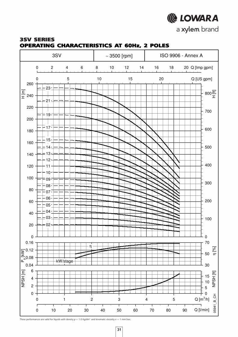
31
These performances are valid for liquids with density ρ = 1.0 Kg/dm3 and kinematic viscosity ν = 1 mm2/sec.
3SV SERIES3SV SERIES3SV SERIES3SV SERIES3SV SERIESOPERAOPERAOPERAOPERAOPERATING CHARACTERISTICTING CHARACTERISTICTING CHARACTERISTICTING CHARACTERISTICTING CHARACTERISTICS AS AS AS AS AT 60Hz, 2 POLEST 60Hz, 2 POLEST 60Hz, 2 POLEST 60Hz, 2 POLEST 60Hz, 2 POLES
Pp
[kW
]
0.04
0.08
0.12
0.16
η [%
]
30
50
70
0 1 2 3 4 5 6
NP
SH
[m]
0
2
4
6
0 10 20 30 40 50 60 70 80 90 100
NP
SH
[ft]
05
1015
H [m
]
0
20
40
60
80
100
120
140
160
180
200
220
240
2600 5 10 15 20 25
H [f
t]
0
100
200
300
400
500
600
700
800
0 2 4 6 8 10 12 14 16 18 20
0594
1_B
_CH
ISO 9906 - Annex A
Q [US gpm]
Q [Imp gpm]
Q [l/min]
Q [m3/h]
η
13
12
11
10
15
kW/stage
∼ 3500 [rpm]
17
23
21
19
14
3SV
02
03
04
05
06
07
08
09

32
5SV SERIES5SV SERIES5SV SERIES5SV SERIES5SV SERIESDIMENSIONS AND WEIGHTS ADIMENSIONS AND WEIGHTS ADIMENSIONS AND WEIGHTS ADIMENSIONS AND WEIGHTS ADIMENSIONS AND WEIGHTS AT 60HzT 60HzT 60HzT 60HzT 60Hz, 2 POLES, 2 POLES, 2 POLES, 2 POLES, 2 POLES
DIMENSIONI E PESI SERIE 5SV 2 poli 60 Hz
PUMP
TYPE ELECTRIC
kW SIZE L1 1 ~ 3 ~ L3 L4 L5 L6 1 ~ 3 ~ 1 ~ 3 ~ D2 PUMP PUMP
5SV02.. 0,55 71 268 231 231 - - 243 243 121 121 140 140 105 8,5 15,2
5SV03../D 0,75 80 303 226 263 - - 278 278 121 129 140 155 120 9,4 19
5SV04../D 1,1 80 328 263 263 - - 303 303 137 129 155 155 120 9,8 21,2
5SV05../D 1,5 90 363 263 263 - - 338 338 137 129 155 155 140 10,6 24
5SV06../D 1,5 90 388 263 263 - - 363 363 137 129 155 155 140 11,1 24,5
5SV07.. 2,2 90 413 298 298 413 242 388 388 151 134 174 174 140 11,6 29,8
5SV08.. 2,2 90 438 298 298 438 267 413 413 151 134 174 174 140 12,1 30,2
5SV09.. 2,2 90 463 298 298 463 292 438 438 151 134 174 174 140 12,5 30,7
5SV10.. 3 100 498 - 298 498 317 473 473 - 134 - 174 160 13,5 34,4
5SV11.. 3 100 523 - 298 523 342 498 498 - 134 - 174 160 13,9 34,9
5SV12.. 3 100 548 - 298 548 367 523 523 - 134 - 174 160 14,4 35,4
5SV13.. 4 112 573 - 319 573 392 548 548 - 154 - 197 160 14,9 41,2
5SV14.. 4 112 598 - 319 598 417 573 573 - 154 - 197 160 15,3 41,7
5SV15.. 4 112 623 - 319 623 442 - 598 - 154 - 197 160 15,8 42,2
5SV16.. 4 112 648 - 319 648 467 - 623 - 154 - 197 160 16,3 42,6
5SV17.. 5,5 132 693 - 375 693 492 - 668 - 168 - 214 300 20,7 58,2
5SV19.. 5,5 132 743 - 375 743 542 - 718 - 168 - 214 300 21,6 59,2
5SV21.. 5,5 132 793 - 375 793 592 - 768 - 168 - 214 300 22,6 60,1
5SV23.. 5,5 132 843 - 375 843 642 - 818 - 168 - 214 300 23,5 61,1
5sv-2p60_c_td
MOTOR WEIGHT kg
D1
DIMENSIONS (mm)
M L2

33
These performances are valid for liquids with density ρ = 1.0 Kg/dm3 and kinematic viscosity ν = 1 mm2/sec.
5SV SERIES5SV SERIES5SV SERIES5SV SERIES5SV SERIESOPERAOPERAOPERAOPERAOPERATING CHARACTERISTICTING CHARACTERISTICTING CHARACTERISTICTING CHARACTERISTICTING CHARACTERISTICS AS AS AS AS AT 60Hz, 2 POLEST 60Hz, 2 POLEST 60Hz, 2 POLEST 60Hz, 2 POLEST 60Hz, 2 POLES
Pp
[kW
]
0.1
0.2
0.3
0.4
η [%
]
20
40
60
80
0 1 2 3 4 5 6 7 8 9 10 11
NP
SH
[m]
0
2
4
6
0 20 40 60 80 100 120 140 160 180
NP
SH
[ft]
05
1015
H [m
]
0
20
40
60
80
100
120
140
160
180
200
220
240
2600 5 10 15 20 25 30 35 40 45
H [f
t]
0
100
200
300
400
500
600
700
800
0 5 10 15 20 25 30 35 40
0594
2_A
_CH
ISO 9906 - Annex A
Q [US gpm]
Q [Imp gpm]
Q [l/min]
Q [m3/h]
∼ 3500 [rpm]
η
14
13
12
11
10
15
16
kW/stage
21
19
17
23
5SV
02
03
04
05
06
07
08
09

34
10SV SERIES10SV SERIES10SV SERIES10SV SERIES10SV SERIESDIMENSIONS AND WEIGHTS ADIMENSIONS AND WEIGHTS ADIMENSIONS AND WEIGHTS ADIMENSIONS AND WEIGHTS ADIMENSIONS AND WEIGHTS AT 60HzT 60HzT 60HzT 60HzT 60Hz, 2 POLES, 2 POLES, 2 POLES, 2 POLES, 2 POLES
DIMENSIONI E PESI SERIE 10SV 2 poli 60 Hz
PUMP
TYPE ELECTRIC
kW SIZE L1 1 ~ 3 ~ L3 L4 L5 L6 1 ~ 3 ~ 1 ~ 3 ~ D2 PUMP PUMP
10SV01../D 0,75 80 357 226 263 - - 357 367 121 129 140 155 120 14,3 24
10SV02../D 1,5 90 367 263 263 - - 367 377 137 129 155 155 140 15,6 29
10SV03.. 2,2 90 399 298 298 - - 399 409 151 134 174 174 140 16,6 34,7
10SV04.. 3 100 441 - 298 - - 441 451 - 134 - 174 160 18,4 39,4
10SV05.. 4 112 473 - 319 473 259 473 483 - 154 - 197 160 19,3 45,7
10SV06.. 4 112 505 - 319 505 291 505 515 - 154 - 197 160 20,3 46,6
10SV07.. 5,5 132 604 - 375 604 323 604 614 - 168 - 214 300 26 63,5
10SV08.. 5,5 132 636 - 375 636 355 636 646 - 168 - 214 300 26,9 64,5
10SV09.. 7,5 132 668 - 367 668 387 668 678 - 191 - 256 300 27,9 83,6
10SV10.. 7,5 132 700 - 367 700 419 - 710 - 191 - 256 300 28,8 84,5
10SV11.. 7,5 132 732 - 367 732 451 - 742 - 191 - 256 300 29,7 85,5
10SV13.. 11 160 826 - 428 826 515 - 836 - 191 - 256 350 34,4 105
10SV15.. 11 160 890 - 428 890 579 - 900 - 191 - 256 350 36,3 107
10sv-2p60_c_td
MOTOR WEIGHT kg
D1
DIMENSIONS (mm)
M L2

35
These performances are valid for liquids with density ρ = 1.0 Kg/dm3 and kinematic viscosity ν = 1 mm2/sec.
10SV SERIES10SV SERIES10SV SERIES10SV SERIES10SV SERIESOPERAOPERAOPERAOPERAOPERATING CHARACTERISTICTING CHARACTERISTICTING CHARACTERISTICTING CHARACTERISTICTING CHARACTERISTICS AS AS AS AS AT 60Hz, 2 POLEST 60Hz, 2 POLEST 60Hz, 2 POLEST 60Hz, 2 POLEST 60Hz, 2 POLES
Pp
[kW
]
0.4
0.6
0.8
1.0
η [%
]
20
40
60
80
0 2 4 6 8 10 12 14 16 18 20
NP
SH
[m]
0
2
4
0 50 100 150 200 250 300
NP
SH
[ft]
0
5
10
H [m
]
0
20
40
60
80
100
120
140
160
180
200
220
240
260
2800 10 20 30 40 50 60 70 80
H [f
t]
0
100
200
300
400
500
600
700
800
900
0 10 20 30 40 50 60 70
0594
3_B
_CH
ISO 9906 - Annex A
Q [US gpm]
Q [Imp gpm]
Q [l/min]
Q [m3/h]
∼ 3500 [rpm]
η
10
kW/stage
10SV
11
13
15
01
02
03
04
05
06
07
08
09

36
15SV SERIES15SV SERIES15SV SERIES15SV SERIES15SV SERIESDIMENSIONS AND WEIGHTS ADIMENSIONS AND WEIGHTS ADIMENSIONS AND WEIGHTS ADIMENSIONS AND WEIGHTS ADIMENSIONS AND WEIGHTS AT 60HzT 60HzT 60HzT 60HzT 60Hz, 2 POLES, 2 POLES, 2 POLES, 2 POLES, 2 POLES
DIMENSIONI E PESI SERIE 15SV 2 poli 60 Hz
PUMP
TYPE ELECTRIC
kW SIZE L1 1 ~ 3 ~ L3 L4 L5 1 ~ 3 ~ 1 ~ 3 ~ D2 PUMP PUMP
15SV01../D 1,5 90 409 263 263 - - 409 137 129 155 155 140 15,4 29
15SV02.. 3 100 419 - 298 - - 419 - 134 - 174 160 17,7 38,7
15SV03.. 4 112 467 - 319 - - 467 - 154 - 197 160 19 45,4
15SV04.. 5,5 132 582 - 375 582 301 582 - 168 - 214 300 25,2 62,7
15SV05.. 7,5 132 630 - 367 630 349 630 - 191 - 256 300 26,5 82,3
15SV06.. 11 160 708 - 428 708 397 708 - 191 - 256 350 30,6 101
15SV07.. 11 160 756 - 428 756 445 756 - 191 - 256 350 32 103
15SV08.. 15 160 804 - 494 804 493 - - 240 - 313 350 33,3 136
15SV09.. 15 160 852 - 494 852 541 - - 240 - 313 350 34,6 137
15SV10.. 15 160 900 - 494 900 589 - - 240 - 313 350 36 138
15SV11.. 18,5 160 948 - 494 948 637 - - 240 - 313 350 37,3 148
15SV12.. 18,5 160 996 - 494 996 685 - - 240 - 313 350 38,6 150
15sv-2p60_c_td
MOTOR WEIGHT kg
D1
DIMENSIONS (mm)
M L2

37
These performances are valid for liquids with density ρ = 1.0 Kg/dm3 and kinematic viscosity ν = 1 mm2/sec.
15SV SERIES15SV SERIES15SV SERIES15SV SERIES15SV SERIESOPERAOPERAOPERAOPERAOPERATING CHARACTERISTICTING CHARACTERISTICTING CHARACTERISTICTING CHARACTERISTICTING CHARACTERISTICS AS AS AS AS AT 60Hz, 2 POLEST 60Hz, 2 POLEST 60Hz, 2 POLEST 60Hz, 2 POLEST 60Hz, 2 POLES
Pp
[kW
]
0.8
1.2
1.6
η [%
]
40
60
80
0 5 10 15 20 25 30 35
NP
SH
[m]
0
2
4
6
0 100 200 300 400 500
NP
SH
[ft]
0481216
H [m
]
0
20
40
60
80
100
120
140
160
180
200
220
240
2600 20 40 60 80 100 120 140
H [f
t]
0
100
200
300
400
500
600
700
800
0 20 40 60 80 100 120
0594
4_C
_CH
ISO 9906 - Annex A
Q [US gpm]
Q [Imp gpm]
Q [l/min]
Q [m3/h]
∼ 3500 [rpm]
η
kW/stage
11
10
12
15SV
01
02
03
04
05
06
07
08
09

38
22SV SERIES22SV SERIES22SV SERIES22SV SERIES22SV SERIESDIMENSIONS AND WEIGHTS ADIMENSIONS AND WEIGHTS ADIMENSIONS AND WEIGHTS ADIMENSIONS AND WEIGHTS ADIMENSIONS AND WEIGHTS AT 60HzT 60HzT 60HzT 60HzT 60Hz, 2 POLES, 2 POLES, 2 POLES, 2 POLES, 2 POLES
DIMENSIONI E PESI SERIE 22SV 2 poli 60 Hz
PUMP
TYPE ELECTRIC
kW SIZE L1 1 ~ 3 ~ L3 L4 L5 1 ~ 3 ~ 1 ~ 3 ~ D2 PUMP PUMP
22SV01.. 2,2 90 409 298 298 - - 409 151 134 174 174 140 15,9 34,1
22SV02.. 4 112 419 - 319 - - 419 - 154 - 197 160 18,1 44,5
22SV03.. 5,5 132 534 - 375 - - 534 - 168 - 214 300 24,3 61,8
22SV04.. 7,5 132 582 - 367 582 301 582 - 191 - 256 300 25,6 81,4
22SV05.. 11 160 660 - 428 660 349 660 - 191 - 256 350 29,8 100
22SV06.. 11 160 708 - 428 708 397 708 - 191 - 256 350 31,1 102
22SV07.. 15 160 756 - 494 756 445 756 - 240 - 313 350 32,4 135
22SV08.. 15 160 804 - 494 804 493 - - 240 - 313 350 33,8 136
22SV09.. 18,5 160 852 - 494 852 541 - - 240 - 313 350 35,1 146
22SV10.. 18,5 160 900 - 494 900 589 - - 240 - 313 350 36,4 148
22sv-2p60_c_td
MOTOR WEIGHT kg
D1
DIMENSIONS (mm)
M L2

39
These performances are valid for liquids with density ρ = 1.0 Kg/dm3 and kinematic viscosity ν = 1 mm2/sec.
22SV SERIES22SV SERIES22SV SERIES22SV SERIES22SV SERIESOPERAOPERAOPERAOPERAOPERATING CHARACTERISTICTING CHARACTERISTICTING CHARACTERISTICTING CHARACTERISTICTING CHARACTERISTICS AS AS AS AS AT 60Hz, 2 POLEST 60Hz, 2 POLEST 60Hz, 2 POLEST 60Hz, 2 POLEST 60Hz, 2 POLES
Pp
[kW
]
1.2
1.6
2.0
η [%
]
40
60
80
0 5 10 15 20 25 30 35 40
NP
SH
[m]
0
5
10
0 100 200 300 400 500 600
NP
SH
[ft]
0
10
20
30
H [m
]
0
20
40
60
80
100
120
140
160
180
200
220
2400 20 40 60 80 100 120 140 160
H [f
t]
0
100
200
300
400
500
600
700
0 20 40 60 80 100 120 140
0594
5_A
_CH
ISO 9906 - Annex A
Q [US gpm]
Q [Imp gpm]
Q [l/min]
Q [m3/h]
∼ 3500 [rpm]
η
kW/stage
10
22SV
09
08
07
06
05
04
03
02
01

40
DIMENSIONI E PESI SERIE 33SV 2 poli 60 Hz
PUMP PUMP
TYPE ELECTRIC TYPE ELECTRIC
kW SIZE L1 L2 D1 D2 M PN PUMP PUMP kW SIZE L1 L2 D1 D2 M PN PUMP PUMP
33SV1/1A.. 3 100 489 298 174 160 134 16 52 73 33SV7.. 30 200 994 657 402 400 317 25 92 307
33SV1.. 5,5 132 509 375 214 300 168 16 57 95 33SV8/2A.. 37 200 1069 657 402 400 317 40 101 331
33SV2/2A.. 5,5 132 584 375 214 300 168 16 61 99 33SV8/1A.. 37 200 1069 657 402 400 317 40 101 331
33SV2/1A.. 7,5 132 584 367 256 300 191 16 61 117 33SV8.. 37 200 1069 657 402 400 317 40 101 331
33SV2.. 11 160 619 428 256 350 191 16 65 136
33SV3/2A.. 11 160 694 428 256 350 191 16 69 140
33SV3/1A.. 11 160 694 428 256 350 191 16 69 140
33SV3.. 15 160 694 494 313 350 240 16 69 171
33SV4/2A.. 15 160 769 494 313 350 240 16 73 175
33SV4/1A.. 15 160 769 494 313 350 240 25 73 175
33SV4.. 18,5 160 769 494 313 350 240 25 73 184
33SV5/2A.. 18,5 160 844 494 313 350 240 25 77 188
33SV5/1A.. 22 180 844 494 313 350 240 25 78 200
33SV5.. 22 180 844 494 313 350 240 25 78 200
33SV6/2A.. 22 180 919 494 313 350 240 25 82 204
33SV6/1A.. 30 200 919 657 402 400 317 25 89 304
33SV6.. 30 200 919 657 402 400 317 25 89 304
33SV7/2A.. 30 200 994 657 402 400 317 25 92 307
33SV7/1A.. 30 200 994 657 402 400 317 25 92 307
33sv-2p60_c_td
DIMENSIONS (mm) WEIGHT kgMOTOR MOTORDIMENSIONS (mm) WEIGHT kg
33SV SERIES33SV SERIES33SV SERIES33SV SERIES33SV SERIESDIMENSIONS AND WEIGHTS ADIMENSIONS AND WEIGHTS ADIMENSIONS AND WEIGHTS ADIMENSIONS AND WEIGHTS ADIMENSIONS AND WEIGHTS AT 60 Hz, 2 POLEST 60 Hz, 2 POLEST 60 Hz, 2 POLEST 60 Hz, 2 POLEST 60 Hz, 2 POLES

41
Pp
[kW
]
1
3
5
η [%
]
40
60
80
0 4 8 12 16 20 24 28 32 36 40 44 48
NP
SH
[m]
0
4
8
12
0 100 200 300 400 500 600 700 800
NP
SH
[ft]
010
2030
H [m
]
0
20
40
60
80
100
120
140
160
180
200
220
240
260
2800 50 100 150 200
H [f
t]
0
100
200
300
400
500
600
700
800
900
0 50 100 150
0511
7B_B
_CH
ISO 9906 - Annex A
Q [US gpm]
Q [Imp gpm]
Q [l/min]
Q [m3/h]
∼ 3500 [rpm]
η
kW/stage
33SV
P2 1
P2 /1
1/1A1
2/2A2/1A2
3/2A3/1A3
4/2A4/1A4
5/2A5/1A5
6/2A6/1A6
7/2A7/1A7
8/2A8/1A8
These performances are valid for liquids with density ρ = 1.0 Kg/dm3 and kinematic viscosity ν = 1 mm2/sec.
33SV SERIES33SV SERIES33SV SERIES33SV SERIES33SV SERIESOPERAOPERAOPERAOPERAOPERATING CHARACTERISTICTING CHARACTERISTICTING CHARACTERISTICTING CHARACTERISTICTING CHARACTERISTICS AS AS AS AS AT 60 Hz, 2 POLEST 60 Hz, 2 POLEST 60 Hz, 2 POLEST 60 Hz, 2 POLEST 60 Hz, 2 POLES

42
DIMENSIONI E PESI SERIE 46SV 2 poli 60 Hz
PUMP PUMP
TYPE ELECTRIC TYPE ELECTRIC
kW SIZE L1 L2 D1 D2 M PN PUMP PUMP kW SIZE L1 L2 D1 D2 M PN PUMP PUMP
46SV1/1A.. 5,5 132 549 375 214 300 168 16 63 101 46SV7.. 45 225 1034 746 455 450 384 40 105 461
46SV1.. 7,5 132 549 367 256 300 191 16 63 119
46SV2/2A.. 11 160 659 428 256 350 191 16 70 141
46SV2/1A.. 11 160 659 428 256 350 191 16 70 141
46SV2.. 15 160 659 494 313 350 240 16 70 172
46SV3/2A.. 18,5 160 734 494 313 350 240 16 74 185
46SV3/1A.. 18,5 160 734 494 313 350 240 16 74 185
46SV3.. 18,5 160 734 494 313 350 240 16 74 185
46SV4/2A.. 22 180 809 494 313 350 240 16 79 201
46SV4/1A.. 30 200 809 657 402 400 317 16 86 301
46SV4.. 30 200 809 657 402 400 317 16 86 301
46SV5/2A.. 30 200 884 657 402 400 317 25 90 305
46SV5/1A.. 30 200 884 657 402 400 317 25 90 305
46SV5.. 30 200 884 657 402 400 317 25 90 305
46SV6/2A.. 37 200 959 657 402 400 317 25 94 324
46SV6/1A.. 37 200 959 657 402 400 317 25 94 324
46SV6.. 37 200 959 657 402 400 317 25 94 324
46SV7/2A.. 45 225 1034 746 455 450 384 40 105 461
46SV7/1A.. 45 225 1034 746 455 450 384 40 105 461
46sv-2p60_a_td
DIMENSIONS (mm) WEIGHT kgMOTOR MOTORDIMENSIONS (mm) WEIGHT kg
46SV SERIES46SV SERIES46SV SERIES46SV SERIES46SV SERIESDIMENSIONS AND WEIGHTS ADIMENSIONS AND WEIGHTS ADIMENSIONS AND WEIGHTS ADIMENSIONS AND WEIGHTS ADIMENSIONS AND WEIGHTS AT 60 Hz, 2 POLEST 60 Hz, 2 POLEST 60 Hz, 2 POLEST 60 Hz, 2 POLEST 60 Hz, 2 POLES

43
Pp
[kW
]
3
5
7
η [%
]
50
60
70
80
0 5 10 15 20 25 30 35 40 45 50 55 60 65 70 75
NP
SH
[m]
0
4
8
0 200 400 600 800 1000 1200
NP
SH
[ft]
0
10
20
H [m
]
0
20
40
60
80
100
120
140
160
180
200
220
240
260
2800 50 100 150 200 250 300
H [f
t]
0
200
400
600
800
0 50 100 150 200 250
0511
8B_B
_CH
ISO 9906 - Annex A
Q [US gpm]
Q [Imp gpm]
Q [l/min]
Q [m3/h]
∼ 3500 [rpm]
η
kW/stage
P2 1
P2 /1
46SV
1/1A1
2/2A2/1A2
3/2A3/1A3
4/2A4/1A4
5/2A5/1A5
6/2A6/1A6
7/2A7/1A7
These performances are valid for liquids with density ρ = 1.0 Kg/dm3 and kinematic viscosity ν = 1 mm2/sec.
46SV SERIES46SV SERIES46SV SERIES46SV SERIES46SV SERIESOPERAOPERAOPERAOPERAOPERATING CHARACTERISTICTING CHARACTERISTICTING CHARACTERISTICTING CHARACTERISTICTING CHARACTERISTICS AS AS AS AS AT 60 Hz, 2 POLEST 60 Hz, 2 POLEST 60 Hz, 2 POLEST 60 Hz, 2 POLEST 60 Hz, 2 POLES

44
DIMENSIONI E PESI SERIE 66SV 2 poli 60 Hz
PUMP
TYPE ELECTRIC
kW SIZE L1 L2 D1 D2 M PN PUMP PUMP
66SV1/1A.. 7,5 132 574 367 256 300 191 16 72 128
66SV1.. 11 160 609 428 256 350 191 16 76 147
66SV2/2A.. 15 160 699 494 313 350 240 16 81 183
66SV2/1A.. 18,5 160 699 494 313 350 240 16 81 192
66SV2.. 18,5 160 699 494 313 350 240 16 81 192
66SV3/2A.. 22 180 789 494 313 350 240 16 87 209
66SV3/1A.. 30 200 789 657 402 400 317 16 94 309
66SV3.. 30 200 789 657 402 400 317 16 94 309
66SV4/2A.. 37 200 879 657 402 400 317 16 100 330
66SV4/1A.. 37 200 879 657 402 400 317 25 102 332
66SV4.. 37 200 879 657 402 400 317 25 102 332
66SV5/2A.. 45 225 969 746 455 450 384 25 111 467
66SV5/1A.. 45 225 969 746 455 450 384 25 111 467
66SV5.. 45 225 969 746 455 450 384 25 111 467
66sv-2p60_a_td
MOTOR DIMENSIONS (mm) WEIGHT kg
66SV SERIES66SV SERIES66SV SERIES66SV SERIES66SV SERIESDIMENSIONS AND WEIGHTS ADIMENSIONS AND WEIGHTS ADIMENSIONS AND WEIGHTS ADIMENSIONS AND WEIGHTS ADIMENSIONS AND WEIGHTS AT 60 Hz, 2 POLEST 60 Hz, 2 POLEST 60 Hz, 2 POLEST 60 Hz, 2 POLEST 60 Hz, 2 POLES

45
Pp
[kW
]
4
6
8
10
η [%
]
50
70
90
0 20 40 60 80 100
NP
SH
[m]
0
5
10
15
0 500 1000 1500
NP
SH
[ft]
0
20
40
H [m
]
0
20
40
60
80
100
120
140
160
180
200
2200 100 200 300 400
H [f
t]
0
100
200
300
400
500
600
700
0 100 200 300 400
0511
9B_C
_CH
ISO 9906 - Annex A
Q [US gpm]
Q [Imp gpm]
Q [l/min]
Q [m3/h]
∼ 3500 [rpm]
η
kW/stage
P2 1
P2 /1
66SV
1/1A
1
2/2A
2/1A
2
3/2A
3/1A
3
4/2A
4/1A
4
5/1A
5/2A
5
These performances are valid for liquids with density ρ = 1.0 Kg/dm3 and kinematic viscosity ν = 1 mm2/sec.
66SV SERIES66SV SERIES66SV SERIES66SV SERIES66SV SERIESOPERAOPERAOPERAOPERAOPERATING CHARACTERISTICTING CHARACTERISTICTING CHARACTERISTICTING CHARACTERISTICTING CHARACTERISTICS AS AS AS AS AT 60 Hz, 2 POLEST 60 Hz, 2 POLEST 60 Hz, 2 POLEST 60 Hz, 2 POLEST 60 Hz, 2 POLES

46
DIMENSIONI E PESI SERIE 92SV 2 poli 60 Hz
PUMP
TYPE ELECTRIC
kW SIZE L1 L2 D1 D2 M PN PUMP PUMP
92SV1/1A.. 11 160 609 428 256 350 191 16 75 146
92SV1.. 15 160 609 494 313 350 240 16 75 177
92SV2/2A.. 18,5 160 699 494 313 350 240 16 80 191
92SV2/1A.. 22 180 699 494 313 350 240 16 82 204
92SV2.. 30 200 699 657 402 400 317 16 89 304
92SV3/2A.. 37 200 789 657 402 400 317 16 94 324
92SV3/1A.. 37 200 789 657 402 400 317 16 94 324
92SV3.. 45 225 789 746 455 450 384 16 97 453
92SV4/2A.. 45 225 879 746 455 450 384 16 103 459
92sv-2p60_a_td
MOTOR DIMENSIONS (mm) WEIGHT kg
92SV SERIES92SV SERIES92SV SERIES92SV SERIES92SV SERIESDIMENSIONS AND WEIGHTS ADIMENSIONS AND WEIGHTS ADIMENSIONS AND WEIGHTS ADIMENSIONS AND WEIGHTS ADIMENSIONS AND WEIGHTS AT 60 Hz, 2 POLEST 60 Hz, 2 POLEST 60 Hz, 2 POLEST 60 Hz, 2 POLEST 60 Hz, 2 POLES

47
Pp
[kW
]
5
10
15
η [%
]
50
60
70
80
0 20 40 60 80 100 120 140
NP
SH
[m]
0
5
10
15
0 500 1000 1500 2000 2500
NP
SH
[ft]
0
20
40
H [m
]
0
20
40
60
80
100
120
140
160
0 100 200 300 400 500 600
H [f
t]
0
100
200
300
400
500
0 100 200 300 400 500
0512
0B_B
_CH
ISO 9906 - Annex A
Q [US gpm]
Q [Imp gpm]
Q [l/min]
Q [m3/h]
∼ 3500 [rpm]
η
kW/stage
P2 1
P2 /1
92SV
1/1A
1
2/2A
2/1A
2
3/2A
3/1A
3
4/2A
These performances are valid for liquids with density ρ = 1.0 Kg/dm3 and kinematic viscosity ν = 1 mm2/sec.
92SV SERIES92SV SERIES92SV SERIES92SV SERIES92SV SERIESOPERAOPERAOPERAOPERAOPERATING CHARACTERISTICTING CHARACTERISTICTING CHARACTERISTICTING CHARACTERISTICTING CHARACTERISTICS AS AS AS AS AT 60 Hz, 2 POLEST 60 Hz, 2 POLEST 60 Hz, 2 POLEST 60 Hz, 2 POLEST 60 Hz, 2 POLES

48
125SV SERIES125SV SERIES125SV SERIES125SV SERIES125SV SERIESDIMENSIONS AND WEIGHTS ADIMENSIONS AND WEIGHTS ADIMENSIONS AND WEIGHTS ADIMENSIONS AND WEIGHTS ADIMENSIONS AND WEIGHTS AT 60 HzT 60 HzT 60 HzT 60 HzT 60 Hz, 2 POLES, 2 POLES, 2 POLES, 2 POLES, 2 POLES
DIMENSIONI E PESI SERIE 125SV 2 poli 60 Hz
PUMP
TYPE ELECTRIC
kW SIZE L1 L2 D1 D2 M PN PUMP PUMP
125SV1.. 15 160 728 494 313 350 240 16 120 222
125SV2/2A.. 22 180 878 494 313 350 240 16 132 253
125SV3/3B.. 30 200 1028 657 402 400 317 16 149 364
125SV3.. 37 200 1028 657 402 400 317 16 150 380
125SV4/4A.. 45 225 1178 746 455 450 384 16 164 520
125SV5/5A.. 55 250 1358 825 486 550 402 25 189 639
125sv-2p60_b_td
MOTOR DIMENSIONS (mm) WEIGHT kg

49
Pp
[kW
]
8
10
12
14
η [%
]
20
40
60
80
0 20 40 60 80 100 120 140 160 180
NP
SH
[m]
0
4
8
12
0 500 1000 1500 2000 2500 3000
NP
SH
[ft]
010
2030
H [m
]
0
20
40
60
80
100
120
140
160
180
2000 100 200 300 400 500 600 700
H [f
t]
0
100
200
300
400
500
600
0 100 200 300 400 500 600
0594
6_B
_CH
ISO 9906 - Annex A
Q [US gpm]
Q [Imp gpm]
Q [l/min]
Q [m3/h]
∼ 3500 [rpm]
η
1
kW/stage
125SV
3
P2 /1AP2 /1B
5/5A
4/4A
3/3B
2/2A
P2 1
These performances are valid for liquids with density ρ = 1.0 Kg/dm3 and kinematic viscosity ν = 1 mm2/sec.
125SV SERIES125SV SERIES125SV SERIES125SV SERIES125SV SERIESOPERAOPERAOPERAOPERAOPERATING CHARACTERISTICTING CHARACTERISTICTING CHARACTERISTICTING CHARACTERISTICTING CHARACTERISTICS AS AS AS AS AT 60 Hz, 2 POLEST 60 Hz, 2 POLEST 60 Hz, 2 POLEST 60 Hz, 2 POLEST 60 Hz, 2 POLES

50

51
Dimensions of counterflanges .........................................................................................................5252525252
Dimensions of Victaulic®, Clamp couplings ....................................................................................5353535353
ACCESACCESACCESACCESACCESSORIESSORIESSORIESSORIESSORIES

52
DIMENSIONS OF ODIMENSIONS OF ODIMENSIONS OF ODIMENSIONS OF ODIMENSIONS OF OVVVVVAL COUNTERFLANGES (T SV)AL COUNTERFLANGES (T SV)AL COUNTERFLANGES (T SV)AL COUNTERFLANGES (T SV)AL COUNTERFLANGES (T SV)
DIMENSIONS OF ROUND THREADED COUNTERFLANGES (FDIMENSIONS OF ROUND THREADED COUNTERFLANGES (FDIMENSIONS OF ROUND THREADED COUNTERFLANGES (FDIMENSIONS OF ROUND THREADED COUNTERFLANGES (FDIMENSIONS OF ROUND THREADED COUNTERFLANGES (F, N, R, N, R, N, R, N, R, N, R, G SV), G SV), G SV), G SV), G SV)ACCORDING TO EN 1092-1ACCORDING TO EN 1092-1ACCORDING TO EN 1092-1ACCORDING TO EN 1092-1ACCORDING TO EN 1092-1
DIMENSIONS OF WELDDIMENSIONS OF WELDDIMENSIONS OF WELDDIMENSIONS OF WELDDIMENSIONS OF WELD-ON ROUND -ON ROUND -ON ROUND -ON ROUND -ON ROUND COUNTERFLANGESCOUNTERFLANGESCOUNTERFLANGESCOUNTERFLANGESCOUNTERFLANGES (G, N SV) (G, N SV) (G, N SV) (G, N SV) (G, N SV)ACCORDING TO EN 1092-1ACCORDING TO EN 1092-1ACCORDING TO EN 1092-1ACCORDING TO EN 1092-1ACCORDING TO EN 1092-1
DIMENSIONI CONTROFLANGE OVALI per 1-2
PUMP
TYPE DN ø C A B D H ø F N° PN
1-3SVT 25 Rp 1 75 12 100 22 11 2 16
5SVT 32 Rp 1¼ 75 12 100 22 11 2 16
10SVT 40 Rp 1½ 100 15 132 25 14 2 16
15-22SVT 50 Rp 2 100 15 132 25 14 2 16
1-22sv-ctf-ovali-en_a_td
DIMENSIONS (mm) HOLES
Round counterflanges Kit available on request:Round counterflanges Kit available on request:Round counterflanges Kit available on request:Round counterflanges Kit available on request:Round counterflanges Kit available on request: Kit containing 2 counterflanges with bolts and gaskets.- threaded, galvanized steel (F, R, G versions).- threaded, AISI 316L stainless steel (N versions).
Standard supply (included with the pump)Standard supply (included with the pump)Standard supply (included with the pump)Standard supply (included with the pump)Standard supply (included with the pump)- AISI 304L stainless steel (T versions).
DIMENSIONI CONTROFLANGE TONDE FILETT
PUMP
TYPE DN ø C ø A B ø D H ø F N° PN
1-3SV 25 Rp 1 85 10 115 16 14 4 25
5SV 32 Rp 1¼ 100 13 140 16 18 4 25
10SV 40 Rp 1½ 110 14 150 19 18 4 25
15-22SV 50 Rp 2 125 16 165 24 18 4 25
33SV 65 Rp 2½ 145 16 185 23 18 4 16
46SV 80 Rp 3 160 17 200 27 18 8 16
66SV-92SV 100 Rp 4 180 18 220 31 18 8 16
1-92sv-ctf-tonde-f-en_a_td
DIMENSIONS (mm) HOLES
DIMENSIONI CONTROFLANGE TONDE A SA
PUMP
TYPE DN ø C ø A B ø D ø F N° PN
33SV 65 77 145 18 185 18 4 16
46SV 80 90 160 20 200 18 8 16
66SV-92SV 100 115,5 180 22 220 18 8 16
125SV 125 141 210 24 250 18 8 16
33SV 65 77 145 24 185 18 8 25-40
46SV 80 90 160 26 200 18 8 25-40
66SV-92SV 100 115,5 190 26 235 22 8 25-40
125SV 125 141 220 28 270 25 8 25-40
33-125sv-ctf-tonde-s-en_a_td
DIMENSIONS (mm) HOLES
Round counterflanges Kit available on request:Round counterflanges Kit available on request:Round counterflanges Kit available on request:Round counterflanges Kit available on request:Round counterflanges Kit available on request:Kit containing 2 counterflanges with bolts and gaskets.- weld-on counterflanges, galvanized steel (G versions).- weld-on counterflanges, AISI 316L stainless steel (N versions).

53
DIMENSIONS OF VICTDIMENSIONS OF VICTDIMENSIONS OF VICTDIMENSIONS OF VICTDIMENSIONS OF VICTAAAAAULICULICULICULICULIC®®®®® COUPLINGS (V SV) COUPLINGS (V SV) COUPLINGS (V SV) COUPLINGS (V SV) COUPLINGS (V SV)
DIMENSIONS OF CLAMP COUPLINGS (C SV)DIMENSIONS OF CLAMP COUPLINGS (C SV)DIMENSIONS OF CLAMP COUPLINGS (C SV)DIMENSIONS OF CLAMP COUPLINGS (C SV)DIMENSIONS OF CLAMP COUPLINGS (C SV)
DIMENSIONI GIUNTI VICTAULIC SV2
PUMP
TYPE ø D4 ø D5 M
1-3-5SV V R 1¼ 42,2 320
10-15-22SV V R 2 60,3 378
1-22sv-giunti-vict-en_a_td
DIMENSIONS (mm)
DIMENSIONI GIUNTI CLAMP 1-22 SV
PUMP
TYPE A B ø D6 ø D7
1-3-5SV C 208 245 35 Rp 1¼
10-15-22SV C 248 301 53 Rp 2
1-22sv-giunti-clamp-en_a_td
DIMENSIONS (mm)
WELD-ON SLEEVES THREADED SLEEVES
WELD-ON SLEEVES THREADED SLEEVES
VVVVVictaulic® couplings kit available on requestictaulic® couplings kit available on requestictaulic® couplings kit available on requestictaulic® couplings kit available on requestictaulic® couplings kit available on request::::: Victaulic® coupling with AISI 316L stainless steel weld-on or threaded sleeve, plus EPDM or FPM gasket. Kits are available for the single version (1 coupling) or double version (2 couplings).
Clamp couplings kit available on requestClamp couplings kit available on requestClamp couplings kit available on requestClamp couplings kit available on requestClamp couplings kit available on request::::: Kit containing 2 Clamp couplings with AISI 316L stainless steel weld-on or threaded sleeve, plus EPDM or FPM gasket. Coupling shape and dimensions according to DIN 32676.
OTHER ACCESOTHER ACCESOTHER ACCESOTHER ACCESOTHER ACCESSORIES:SORIES:SORIES:SORIES:SORIES:- Dry running sensorDry running sensorDry running sensorDry running sensorDry running sensor Optical sensor for detecting the lack of water in order to prevent damage deriving from dry running. This accessory can be applied at the filling tap.
- i-ALERT™i-ALERT™i-ALERT™i-ALERT™i-ALERT™ Patented i-ALERT™ monitor continuously measures vibration to support optimum performance. Available on requeston requeston requeston requeston request on pumps < 7,5 kW (10 HP).

54
SPECIAL VERSIONS ON REQUESTSPECIAL VERSIONS ON REQUESTSPECIAL VERSIONS ON REQUESTSPECIAL VERSIONS ON REQUESTSPECIAL VERSIONS ON REQUEST
More and more customers require specific solutions for satisfying particular application requirements.To meet their needs, Lowara offers a series of variants for personalising the e-SVTM pumps.
• High Pressure (50/60 Hz)High Pressure (50/60 Hz)High Pressure (50/60 Hz)High Pressure (50/60 Hz)High Pressure (50/60 Hz) Water treatment industry - washing and cleaning - Versatile range - Long lasting performances - Easy installation and maintenance
• Low NPSH (50/60 Hz)Low NPSH (50/60 Hz)Low NPSH (50/60 Hz)Low NPSH (50/60 Hz)Low NPSH (50/60 Hz) Solving cavitation issues in installation - Consistent operation - Long lasting performances - Easy installation
• High THigh THigh THigh THigh Temperatureemperatureemperatureemperatureemperature Electric pumps for high temperature applications - HHHHH versions for temperature values up to 150°C - BBBBB “BOILER”versions for temperature values up to 180°C
• e-SVH - e-SVH - e-SVH - e-SVH - e-SVH - e-SVe-SVe-SVe-SVe-SVTMTMTMTMTM with HYDRO with HYDRO with HYDRO with HYDRO with HYDROVVVVVARARARARAR®®®®®
An evolution of e-SVTM special version toward a variable speed intelligent system
• 4-POLE V4-POLE V4-POLE V4-POLE V4-POLE Version (50/60 Hz)ersion (50/60 Hz)ersion (50/60 Hz)ersion (50/60 Hz)ersion (50/60 Hz) Silencious operation - Low level of noise - Wide range of performances - Increased performance with Hydrovar®
• Reducing FReducing FReducing FReducing FReducing Footprint (50/60 Hz)ootprint (50/60 Hz)ootprint (50/60 Hz)ootprint (50/60 Hz)ootprint (50/60 Hz) Space saving in installation - Compact design - Versatile design - High level performances
• PPPPPassivated and electro-polished versionassivated and electro-polished versionassivated and electro-polished versionassivated and electro-polished versionassivated and electro-polished version All e-SVTM pump components are passivated and electro-polished in order to reduce the risk of corrosion and to comply with specific hygiene requirements.
• Horizontal VHorizontal VHorizontal VHorizontal VHorizontal Version (50/60 Hz)ersion (50/60 Hz)ersion (50/60 Hz)ersion (50/60 Hz)ersion (50/60 Hz) Installation in reduced vertical space or in sismic area - Reduced vertical space - Easy installation
• MotorsMotorsMotorsMotorsMotors Wide range of high efficiency motors - 50 and 60 Hz - Wide range of voltages - Wide range of standard options
• Protection sensor against dry runningProtection sensor against dry runningProtection sensor against dry runningProtection sensor against dry runningProtection sensor against dry running Sensor for detecting the lack of liquid
• i-ALERT™ - Conditional Monitoringi-ALERT™ - Conditional Monitoringi-ALERT™ - Conditional Monitoringi-ALERT™ - Conditional Monitoringi-ALERT™ - Conditional Monitoring Reduce life cycle cost by increasing Mean Time between Failures (MTBF)
• CertificatesCertificatesCertificatesCertificatesCertificates List of the main tests and certificates available for e-SVTM
• AccessoriesAccessoriesAccessoriesAccessoriesAccessories Wide range of accessories for connection and installation
• VVVVVersion with stainless steel baseersion with stainless steel baseersion with stainless steel baseersion with stainless steel baseersion with stainless steel base The SV pump can be supplied with a stainless steel base for applications in aggressive conditions.
For more information, please see e-SVTM Special Versions catalogue.

55
TECHNICALTECHNICALTECHNICALTECHNICALTECHNICALAPPENDIXAPPENDIXAPPENDIXAPPENDIXAPPENDIX

56TECHNICAL APPENDIXTECHNICAL APPENDIXTECHNICAL APPENDIXTECHNICAL APPENDIXTECHNICAL APPENDIX
The minimum operating values that can be reached at thepump suction end are limited by the onset of cavitation.
Cavitation is the formation of vapour-filled cavities withinliquids where the pressure is locally reduced to a critical value,or where the local pressure is equal to, or just below thevapour pressure of the liquid.
The vapour-filled cavities flow with the current andwhen they reach a higher pressure area the vapourcontained in the cavities condenses. The cavities collide,generating pressure waves that are transmitted to thewalls. These, being subjected to stress cycles, graduallybecome deformed and yield due to fatigue. Thisphenomenon, characterized by a metallic noiseproduced by the hammering on the pipe walls, is calledincipient cavitation.
The damage caused by cavitation may be magnified byelectrochemical corrosion and a local rise intemperature due to the plastic deformation of thewalls. The materials that offer the highest resistance toheat and corrosion are alloy steels, especially austeniticsteel. The conditions that trigger cavitation may beassessed by calculating the total net suction head,referred to in technical literature with the acronymNPSH (Net Positive Suction Head).
The NPSH represents the total energy (expressed in m.)of the liquid measured at suction under conditions ofincipient cavitation, excluding the vapour pressure(expressed in m.) that the liquid has at the pump inlet.
To find the static height hz at which to install themachine under safe conditions, the following formulamust be verified:
hp + hz ≥ (NPSHr + 0.5) + hf + hpv
where:hp is the absolute pressure applied to the free liquid surface in the suction tank, expressed in m. of liquid; hp is the quotient between the barometric pressure and the specific weight of the liquid.hz is the suction lift between the pump axis and the free liquid surface in the suction tank, expressed in m.; hz is negative when the liquid level is lower than the pump axis.hf is the flow resistance in the suction line and its accessories, such as: fittings, foot valve, gate valve, elbows, etc.hpv is the vapour pressure of the liquid at the operating temperature, expressed in m. of liquid. hpv is the quotient between the Pv vapour pressure and the liquid’s specific weight.0,5 is the safety factor.
The maximum possible suction head for installationdepends on the value of the atmospheric pressure(i.e. the elevation above sea level at which the pumpis installed) and the temperature of the liquid.
To help the user, with reference to water temperature(4° C) and to the elevation above sea level, thefollowing tables show the drop in hydraulic pressurehead in relation to the elevation above sea level, andthe suction loss in relation to temperature.
Friction loss is shown in the tables at pages 58-59 ofthis catalogue. To reduce it to a minimum, especiallyin cases of high suction head (over 4-5 m.) or withinthe operating limits with high flow rates, werecommend using a suction line having a largerdiameter than that of the pump’s suction port.It is always a good idea to position the pump as closeas possible to the liquid to be pumped.
Make the following calculation:
Liquid: water at ~15°C γ = 1 kg/dm3
Flow rate required: 25 m3/hHead for required delivery: 70 m.Suction lift: 3,5 m.The selection is an 33SVG075T pump whose NPSHrequired value is, at 25 m3/h, di 2 m.
For water at 15 °C
hp = Pa / γ = 10,33m, hpv = Pv / γ = 0,174m (0,01701 bar)
The Hf flow resistance in the suction line with footvalves is ~ 1,2 m.By substituting the parameters in formula with thenumeric values above, we have:
10,33 + (-3,5) ≥ (2 + 0,5) + 1,2 + 0,17
from which we have: 6,8 > 3,9
The relation is therefore verified.
Water temperature (°C) 20 40 60 80 90 110 120
Suction loss (m) 0,2 0,7 2,0 5,0 7,4 15,4 21,5
Elevation above sea level (m) 500 1000 1500 2000 2500 3000
Suction loss (m) 0,55 1,1 1,65 2,2 2,75 3,3
NPSHNPSHNPSHNPSHNPSH
1
1
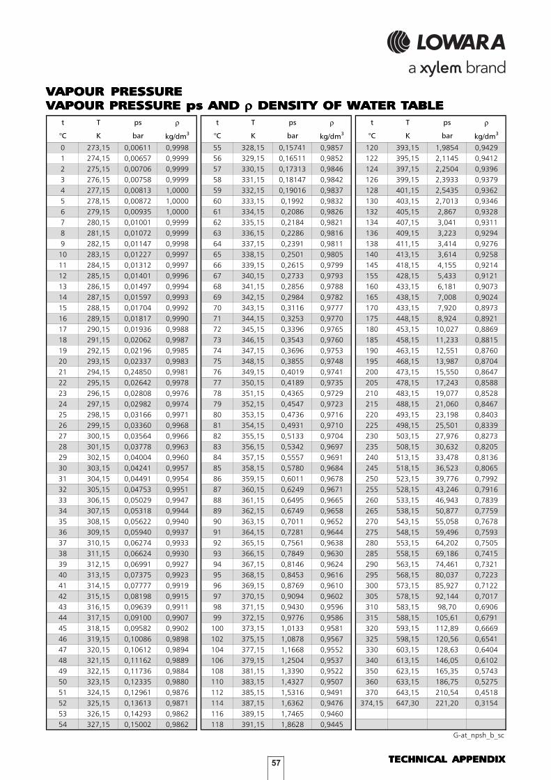
57 TECHNICAL APPENDIXTECHNICAL APPENDIXTECHNICAL APPENDIXTECHNICAL APPENDIXTECHNICAL APPENDIX
VVVVVAPOUR PRESAPOUR PRESAPOUR PRESAPOUR PRESAPOUR PRESSURESURESURESURESUREVVVVVAPOUR PRESAPOUR PRESAPOUR PRESAPOUR PRESAPOUR PRESSURE ps AND SURE ps AND SURE ps AND SURE ps AND SURE ps AND ρρρρρ DENSITY OF WA DENSITY OF WA DENSITY OF WA DENSITY OF WA DENSITY OF WATER TTER TTER TTER TTER TABLEABLEABLEABLEABLE
TENSIONE DI VAPORETABELLA TENSIONE DI VAPORE ps E DENSITA' DELL'ACQUA
t T ps ρ t T ps ρ t T ps ρ
°C K bar kg/dm3 °C K bar kg/dm
3 °C K bar kg/dm3
0 273,15 0,00611 0,9998 55 328,15 0,15741 0,9857 120 393,15 1,9854 0,9429
1 274,15 0,00657 0,9999 56 329,15 0,16511 0,9852 122 395,15 2,1145 0,9412
2 275,15 0,00706 0,9999 57 330,15 0,17313 0,9846 124 397,15 2,2504 0,9396
3 276,15 0,00758 0,9999 58 331,15 0,18147 0,9842 126 399,15 2,3933 0,9379
4 277,15 0,00813 1,0000 59 332,15 0,19016 0,9837 128 401,15 2,5435 0,9362
5 278,15 0,00872 1,0000 60 333,15 0,1992 0,9832 130 403,15 2,7013 0,9346
6 279,15 0,00935 1,0000 61 334,15 0,2086 0,9826 132 405,15 2,867 0,9328
7 280,15 0,01001 0,9999 62 335,15 0,2184 0,9821 134 407,15 3,041 0,9311
8 281,15 0,01072 0,9999 63 336,15 0,2286 0,9816 136 409,15 3,223 0,9294
9 282,15 0,01147 0,9998 64 337,15 0,2391 0,9811 138 411,15 3,414 0,9276
10 283,15 0,01227 0,9997 65 338,15 0,2501 0,9805 140 413,15 3,614 0,9258
11 284,15 0,01312 0,9997 66 339,15 0,2615 0,9799 145 418,15 4,155 0,9214
12 285,15 0,01401 0,9996 67 340,15 0,2733 0,9793 155 428,15 5,433 0,9121
13 286,15 0,01497 0,9994 68 341,15 0,2856 0,9788 160 433,15 6,181 0,9073
14 287,15 0,01597 0,9993 69 342,15 0,2984 0,9782 165 438,15 7,008 0,9024
15 288,15 0,01704 0,9992 70 343,15 0,3116 0,9777 170 433,15 7,920 0,8973
16 289,15 0,01817 0,9990 71 344,15 0,3253 0,9770 175 448,15 8,924 0,8921
17 290,15 0,01936 0,9988 72 345,15 0,3396 0,9765 180 453,15 10,027 0,8869
18 291,15 0,02062 0,9987 73 346,15 0,3543 0,9760 185 458,15 11,233 0,8815
19 292,15 0,02196 0,9985 74 347,15 0,3696 0,9753 190 463,15 12,551 0,8760
20 293,15 0,02337 0,9983 75 348,15 0,3855 0,9748 195 468,15 13,987 0,8704
21 294,15 0,24850 0,9981 76 349,15 0,4019 0,9741 200 473,15 15,550 0,8647
22 295,15 0,02642 0,9978 77 350,15 0,4189 0,9735 205 478,15 17,243 0,8588
23 296,15 0,02808 0,9976 78 351,15 0,4365 0,9729 210 483,15 19,077 0,8528
24 297,15 0,02982 0,9974 79 352,15 0,4547 0,9723 215 488,15 21,060 0,8467
25 298,15 0,03166 0,9971 80 353,15 0,4736 0,9716 220 493,15 23,198 0,8403
26 299,15 0,03360 0,9968 81 354,15 0,4931 0,9710 225 498,15 25,501 0,8339
27 300,15 0,03564 0,9966 82 355,15 0,5133 0,9704 230 503,15 27,976 0,8273
28 301,15 0,03778 0,9963 83 356,15 0,5342 0,9697 235 508,15 30,632 0,8205
29 302,15 0,04004 0,9960 84 357,15 0,5557 0,9691 240 513,15 33,478 0,8136
30 303,15 0,04241 0,9957 85 358,15 0,5780 0,9684 245 518,15 36,523 0,8065
31 304,15 0,04491 0,9954 86 359,15 0,6011 0,9678 250 523,15 39,776 0,7992
32 305,15 0,04753 0,9951 87 360,15 0,6249 0,9671 255 528,15 43,246 0,7916
33 306,15 0,05029 0,9947 88 361,15 0,6495 0,9665 260 533,15 46,943 0,7839
34 307,15 0,05318 0,9944 89 362,15 0,6749 0,9658 265 538,15 50,877 0,7759
35 308,15 0,05622 0,9940 90 363,15 0,7011 0,9652 270 543,15 55,058 0,7678
36 309,15 0,05940 0,9937 91 364,15 0,7281 0,9644 275 548,15 59,496 0,7593
37 310,15 0,06274 0,9933 92 365,15 0,7561 0,9638 280 553,15 64,202 0,7505
38 311,15 0,06624 0,9930 93 366,15 0,7849 0,9630 285 558,15 69,186 0,7415
39 312,15 0,06991 0,9927 94 367,15 0,8146 0,9624 290 563,15 74,461 0,7321
40 313,15 0,07375 0,9923 95 368,15 0,8453 0,9616 295 568,15 80,037 0,7223
41 314,15 0,07777 0,9919 96 369,15 0,8769 0,9610 300 573,15 85,927 0,7122
42 315,15 0,08198 0,9915 97 370,15 0,9094 0,9602 305 578,15 92,144 0,7017
43 316,15 0,09639 0,9911 98 371,15 0,9430 0,9596 310 583,15 98,70 0,6906
44 317,15 0,09100 0,9907 99 372,15 0,9776 0,9586 315 588,15 105,61 0,6791
45 318,15 0,09582 0,9902 100 373,15 1,0133 0,9581 320 593,15 112,89 0,6669
46 319,15 0,10086 0,9898 102 375,15 1,0878 0,9567 325 598,15 120,56 0,6541
47 320,15 0,10612 0,9894 104 377,15 1,1668 0,9552 330 603,15 128,63 0,6404
48 321,15 0,11162 0,9889 106 379,15 1,2504 0,9537 340 613,15 146,05 0,6102
49 322,15 0,11736 0,9884 108 381,15 1,3390 0,9522 350 623,15 165,35 0,5743
50 323,15 0,12335 0,9880 110 383,15 1,4327 0,9507 360 633,15 186,75 0,5275
51 324,15 0,12961 0,9876 112 385,15 1,5316 0,9491 370 643,15 210,54 0,4518
52 325,15 0,13613 0,9871 114 387,15 1,6362 0,9476 374,15 647,30 221,20 0,3154
53 326,15 0,14293 0,9862 116 389,15 1,7465 0,9460
54 327,15 0,15002 0,9862 118 391,15 1,8628 0,9445
G-at_npsh_b_sc
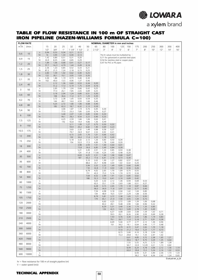
58TECHNICAL APPENDIXTECHNICAL APPENDIXTECHNICAL APPENDIXTECHNICAL APPENDIXTECHNICAL APPENDIX
TTTTTABLE OF FLABLE OF FLABLE OF FLABLE OF FLABLE OF FLOW RESISTOW RESISTOW RESISTOW RESISTOW RESISTANCE IN 100 m OF STRAIGHT CASTANCE IN 100 m OF STRAIGHT CASTANCE IN 100 m OF STRAIGHT CASTANCE IN 100 m OF STRAIGHT CASTANCE IN 100 m OF STRAIGHT CASTIRON PIPELINE (HAZEN-IRON PIPELINE (HAZEN-IRON PIPELINE (HAZEN-IRON PIPELINE (HAZEN-IRON PIPELINE (HAZEN-WILLIAMS FORMULA C=100)WILLIAMS FORMULA C=100)WILLIAMS FORMULA C=100)WILLIAMS FORMULA C=100)WILLIAMS FORMULA C=100)
m3/h l/min 15 20 25 32 40 50 65 80 100 125 150 175 200 250 300 350 400
1/2" 3/4" 1" 1 1/4" 1 1/2" 2 2 1/2" 3" 4" 5" 6" 7" 8" 10" 12" 14" 16"v 0,94 0,53 0,34 0,21 0,13
hr 16 3,94 1,33 0,40 0,13 The hr values must be multiplied by:
v 1,42 0,80 0,51 0,31 0,20 0,71 for galvanized or painted steel pipes
hr 33,9 8,35 2,82 0,85 0,29 0,54 for stainless steel or copper pipes
v 1,89 1,06 0,68 0,41 0,27 0,17 0,47 for PVC or PE pipes
hr 57,7 14,21 4,79 1,44 0,49 0,16
v 2,36 1,33 0,85 0,52 0,33 0,21
hr 87,2 21,5 7,24 2,18 0,73 0,25
v 2,83 1,59 1,02 0,62 0,40 0,25
hr 122 30,1 10,1 3,05 1,03 0,35
v 3,30 1,86 1,19 0,73 0,46 0,30
hr 162 40,0 13,5 4,06 1,37 0,46
v 2,12 1,36 0,83 0,53 0,34 0,20
hr 51,2 17,3 5,19 1,75 0,59 0,16
v 2,65 1,70 1,04 0,66 0,42 0,25
hr 77,4 26,1 7,85 2,65 0,89 0,25
v 3,18 2,04 1,24 0,80 0,51 0,30
hr 108 36,6 11,0 3,71 1,25 0,35
v 3,72 2,38 1,45 0,93 0,59 0,35
hr 144 48,7 14,6 4,93 1,66 0,46
v 4,25 2,72 1,66 1,06 0,68 0,40
hr 185 62,3 18,7 6,32 2,13 0,59
v 3,06 1,87 1,19 0,76 0,45 0,30
hr 77,5 23,3 7,85 2,65 0,74 0,27
v 3,40 2,07 1,33 0,85 0,50 0,33
hr 94,1 28,3 9,54 3,22 0,90 0,33
v 4,25 2,59 1,66 1,06 0,63 0,41
hr 142 42,8 14,4 4,86 1,36 0,49
v 3,11 1,99 1,27 0,75 0,50 0,32
hr 59,9 20,2 6,82 1,90 0,69 0,23
v 3,63 2,32 1,49 0,88 0,58 0,37
hr 79,7 26,9 9,07 2,53 0,92 0,31
v 4,15 2,65 1,70 1,01 0,66 0,42
hr 102 34,4 11,6 3,23 1,18 0,40
v 5,18 3,32 2,12 1,26 0,83 0,53 0,34
hr 154 52,0 17,5 4,89 1,78 0,60 0,20
v 3,98 2,55 1,51 1,00 0,64 0,41
hr 72,8 24,6 6,85 2,49 0,84 0,28
v 5,31 3,40 2,01 1,33 0,85 0,54 0,38
hr 124 41,8 11,66 4,24 1,43 0,48 0,20
v 6,63 4,25 2,51 1,66 1,06 0,68 0,47
hr 187 63,2 17,6 6,41 2,16 0,73 0,30
v 5,10 3,02 1,99 1,27 0,82 0,57 0,42
hr 88,6 24,7 8,98 3,03 1,02 0,42 0,20
v 5,94 3,52 2,32 1,49 0,95 0,66 0,49
hr 118 32,8 11,9 4,03 1,36 0,56 0,26
v 6,79 4,02 2,65 1,70 1,09 0,75 0,55
hr 151 42,0 15,3 5,16 1,74 0,72 0,34
v 7,64 4,52 2,99 1,91 1,22 0,85 0,62
hr 188 52,3 19,0 6,41 2,16 0,89 0,42
v 5,03 3,32 2,12 1,36 0,94 0,69 0,53
hr 63,5 23,1 7,79 2,63 1,08 0,51 0,27
v 6,28 4,15 2,65 1,70 1,18 0,87 0,66
hr 96,0 34,9 11,8 3,97 1,63 0,77 0,40
v 7,54 4,98 3,18 2,04 1,42 1,04 0,80
hr 134 48,9 16,5 5,57 2,29 1,08 0,56
v 8,79 5,81 3,72 2,38 1,65 1,21 0,93
hr 179 65,1 21,9 7,40 3,05 1,44 0,75
v 6,63 4,25 2,72 1,89 1,39 1,06 0,68
hr 83,3 28,1 9,48 3,90 1,84 0,96 0,32
v 8,29 5,31 3,40 2,36 1,73 1,33 0,85
hr 126 42,5 14,3 5,89 2,78 1,45 0,49
v 6,37 4,08 2,83 2,08 1,59 1,02 0,71
hr 59,5 20,1 8,26 3,90 2,03 0,69 0,28
v 7,43 4,76 3,30 2,43 1,86 1,19 0,83
hr 79,1 26,7 11,0 5,18 2,71 0,91 0,38
v 8,49 5,44 3,77 2,77 2,12 1,36 0,94
hr 101 34,2 14,1 6,64 3,46 1,17 0,48
v 6,79 4,72 3,47 2,65 1,70 1,18
hr 51,6 21,2 10,0 5,23 1,77 0,73
v 8,15 5,66 4,16 3,18 2,04 1,42
hr 72,3 29,8 14,1 7,33 2,47 1,02
v 6,61 4,85 3,72 2,38 1,65 1,21
hr 39,6 18,7 9,75 3,29 1,35 0,64
v 7,55 5,55 4,25 2,72 1,89 1,39
hr 50,7 23,9 12,49 4,21 1,73 0,82
v 8,49 6,24 4,78 3,06 2,12 1,56 1,19
hr 63,0 29,8 15,5 5,24 2,16 1,02 0,53
v 6,93 5,31 3,40 2,36 1,73 1,33
hr 36,2 18,9 6,36 2,62 1,24 0,65
G-at-pct-en_a_th
hr = flow resistance for 100 m of straight pipeline (m)
V = water speed (m/s)
105 1750
42 700
54 900
9
7,5 125
FLOW RATE NOMINAL DIAMETER in mm and inches
40
3,6 60
25
2,4
0,9 15
0,6
6 100
5,4
1,2 20
1,8 30
2,1 35
1,5
10
30
4,2 70
3 50
150
12 200
4,8 80
400
90
175
48
36
24
15
10,5
18 300
250
100060
90
75 1250
500
800
600
180 3000
2000120
150 2500
1500
210 3500
360 6000
240 4000
300 5000
420 7000
600 10000
8000480
540 9000

59 TECHNICAL APPENDIXTECHNICAL APPENDIXTECHNICAL APPENDIXTECHNICAL APPENDIXTECHNICAL APPENDIX
FLFLFLFLFLOW RESISTOW RESISTOW RESISTOW RESISTOW RESISTANCEANCEANCEANCEANCETTTTTABLE OF FLABLE OF FLABLE OF FLABLE OF FLABLE OF FLOW RESISTOW RESISTOW RESISTOW RESISTOW RESISTANCE IN BENDS, VANCE IN BENDS, VANCE IN BENDS, VANCE IN BENDS, VANCE IN BENDS, VALALALALALVES ANDVES ANDVES ANDVES ANDVES ANDGAGAGAGAGATESTESTESTESTES
The flow resistance is calculated using the equivalent pipeline length method according to the table below:
The table is valid for the Hazen Williams coefficient C=100 (cast iron pipework);for steel pipework, multiply the values by 1,41;for stainless steel, copper and coated cast iron pipework, multiply the values by 1,85;When the equivalent pipeline length equivalent pipeline length equivalent pipeline length equivalent pipeline length equivalent pipeline length has been determined, the flow resistance is obtained from the table offlow resistance.The values given are guideline values which are bound to vary slightly according to the model, especially for gatevalves and non-return valves, for which it is a good idea to check the values supplied by manufacturers.
TABELLA LUNGHEZZA DI TUBAZIONE EQUIVALENTE
ACCESSORY
TYPE 25 32 40 50 65 80 100 125 150 200 250 300
45° bend 0,2 0,2 0,4 0,4 0,6 0,6 0,9 1,1 1,5 1,9 2,4 2,8
90° bend 0,4 0,6 0,9 1,1 1,3 1,5 2,1 2,6 3,0 3,9 4,7 5,8
90° smooth bend 0,4 0,4 0,4 0,6 0,9 1,1 1,3 1,7 1,9 2,8 3,4 3,9
Union tee or cross 1,1 1,3 1,7 2,1 2,6 3,2 4,3 5,3 6,4 7,5 10,7 12,8
Gate - - - 0,2 0,2 0,2 0,4 0,4 0,6 0,9 1,1 1,3
Non return valve 1,1 1,5 1,9 2,4 3,0 3,4 4,7 5,9 7,4 9,6 11,8 13,9
G-a-pcv-en_a_th
DN
Equivalent pipeline length (m)

60TECHNICAL APPENDIXTECHNICAL APPENDIXTECHNICAL APPENDIXTECHNICAL APPENDIXTECHNICAL APPENDIX
VOLUMETRIC CAPACITYVOLUMETRIC CAPACITY
Litres Cubic metres Cubic feet Cubic feet Imp. gal. US gal.
per minute per hour per hour per minute per minute per minute
l/min m3/h ft
3/h ft
3/min Imp. gal/min Us gal./min
1,0000 0,0600 2,1189 0,0353 0,2200 0,2642
16,6667 1,0000 35,3147 0,5886 3,6662 4,4029
0,4719 0,0283 1,0000 0,0167 0,1038 0,1247
28,3168 1,6990 60,0000 1,0000 6,2288 7,4805
4,5461 0,2728 9,6326 0,1605 1,0000 1,2009
3,7854 0,2271 8,0208 0,1337 0,8327 1,0000
PRESSURE AND HEADPRESSURE AND HEAD
Newton per kilo Pascal bar Pound force per metre millimetre of
square metre square inch of water mercury
N/m2 kPa bar psi m H2O mm Hg
1,0000 0,0010 1 x 10⁻⁵ 1.45 x 10⁻⁴ 1.02 x 10⁻⁴ 0,0075
1000,0000 1,0000 0,0100 0,1450 0,1020 7,5006
1 x 10⁵ 100,0000 1,0000 14,5038 10,1972 750,0638
6894,7570 6,8948 0,0689 1,0000 0,7031 51,7151
9806,6500 9,8067 0,0981 1,4223 1,0000 73,5561
133,3220 0,1333 0,0013 0,0193 0,0136 1,0000
LENGTHLENGTH
millimetre centimetre metre inch foot yard
mm cm m in ft yd
1,0000 0,1000 0,0010 0,0394 0,0033 0,0011
10,0000 1,0000 0,0100 0,3937 0,0328 0,01091000,0000 100,0000 1,0000 39,3701 3,2808 1,0936
25,4000 2,5400 0,0254 1,0000 0,0833 0,0278
304,8000 30,4800 0,3048 12,0000 1,0000 0,3333
914,4000 91,4400 0,9144 36,0000 3,0000 1,0000
VOLUMEVOLUME
cubic metre litre millilitre imp. Gallon US gallon cubic foot
m3 litro ml imp. gal. US gal. ft
3
1,0000 1000,0000 1 x 10⁶ 219,9694 264,1720 35,3147
0,0010 1,0000 1000,0000 0,2200 0,2642 0,0353
1 x 10⁻⁶ 0,0010 1,0000 2.2 x 10⁻⁴ 2.642 x 10-43.53 x 10
-5
0,0045 4,5461 4546,0870 1,0000 1,2009 0,1605
0,0038 3,7854 3785,4120 0,8327 1,0000 0,1337
0,0283 28,3168 28316,8466 6,2288 7,4805 1,0000
G-at_pp-en_a_sc
VVVVVOLOLOLOLOLUMETRIC CAPUMETRIC CAPUMETRIC CAPUMETRIC CAPUMETRIC CAPACITYACITYACITYACITYACITY
PRESPRESPRESPRESPRESSURE AND HEADSURE AND HEADSURE AND HEADSURE AND HEADSURE AND HEAD
LENGLENGLENGLENGLENGTHTHTHTHTH
VVVVVOLOLOLOLOLUMEUMEUMEUMEUME

61 TECHNICAL APPENDIXTECHNICAL APPENDIXTECHNICAL APPENDIXTECHNICAL APPENDIXTECHNICAL APPENDIX
FURTHER PRODUCT SELECTION AND DOCUMENTFURTHER PRODUCT SELECTION AND DOCUMENTFURTHER PRODUCT SELECTION AND DOCUMENTFURTHER PRODUCT SELECTION AND DOCUMENTFURTHER PRODUCT SELECTION AND DOCUMENTAAAAATIONTIONTIONTIONTION
XylectXylectXylectXylectXylect
Xylect is pump solution selection software with an extensive online database of product information across the entireLowara, and Vogel range of pumps and related products, with multiple search options and helpful project managementfacilities. The system holds up-to-date product information on thousands of products and accessories.
The possibility to search by applications and the detailed information output given makes it easy to make the optimalselection without having detailed knowledge about the Lowara and Vogel products.
The search can be made by:
• Application
• Product type
• Duty point
Xylect gives a detailed output:
• List with search results
• Performance curves (flow, head, power,efficiency, NPSH)
• Motor data
• Dimensional drawings
• Options
• Data sheet printouts
• Document downloads incl dxf filesThe search by application guides users not familiar withthe product range to the right choice.

62TECHNICAL APPENDIXTECHNICAL APPENDIXTECHNICAL APPENDIXTECHNICAL APPENDIXTECHNICAL APPENDIX
FURTHER PRODUCT SELECTION AND DOCUMENTFURTHER PRODUCT SELECTION AND DOCUMENTFURTHER PRODUCT SELECTION AND DOCUMENTFURTHER PRODUCT SELECTION AND DOCUMENTFURTHER PRODUCT SELECTION AND DOCUMENTAAAAATIONTIONTIONTIONTION
XylectXylectXylectXylectXylect
The detailed output makes it easy to select the optimal pump from the given alternatives.
The best way to work with Xylect is to create apersonal account. This makes it possible to:
• Set own standard units
• Create and save projects
• Share projects with other Xylect users
Every user have a My Xylect space, where all projectsare saved.
For more information about Xylect please contactour sales network or visit www.xylect.com.
Dimensional drawings appear on the screen and can bedownloaded in dxf format.


Xylem1) The tissue in plants that brings water upward from the roots; 2) a leading global water technology company.
We’re 12,000 people unifi ed in a common purpose: creating innovative solutions to meet our world’s water needs. Developing new technologies that will improve the way water is used, conserved, and re-used in the future is central to our work. We move, treat, analyze, and return water to the environment, and we help people use water effi ciently, in their homes, buildings, factories and farms. In more than 150 countries, we have strong, long-standing relationships with customers who know us for our powerful combination of leading product brands and applications expertise, backed by a legacy of innovation.
For more information on how Xylem can help you, go to xyleminc.com.
Headquarters
LOWARA S.r.l. UnipersonaleVia Vittorio Lombardi 1436075 Montecchio Maggiore - Vicenza - ItalyTel.(+39) 0444 707111 - Fax(+39) 0444 492166e-mail: [email protected]: www.lowara.com - www.completewatersystems.comLOWARA reserves the right to make modifi cation without prior notice.LOWARA is a trademark of Xylem Inc. or one of its subsidiaries.