Embed Size (px)
Citation preview

SPD Product Catalogue 2010
Low VoltageSurge ProtectionAustralia & New Zealand
Eaton Surge Protection2
Why do I need surge protection?If a surge is of sufficient energy level then it can damage or destroy electrical equipment or even the electrical infrastructure itself. Direct & indirect costs to a business can be very expensive. A surge protection device is in real terms very in- expensive & when correctly selected & installed can prevent damage occurring.
What is a surge?A surge is a random, short burst of excess electrical energy to a system. It is typically measured in micro & milli-seconds. Also referred to as a transient, impulse or spike, these electrical disturbances can damage or even destroy sensitive microprocessor-based equipment. Surge protection devices are designed to reduce the amount of harmful energy that flows into a system.
Where do they come from?80% of transients are generated from internal sources such as load switching, motors starting up or even turning on air conditioning systems. The other 20% of transients are typically generated from external sources such as lightning strikes & power company grid switching. Like it or not, most electrical systems are subjected to some level of transients. What is SPD?Referred to as Surge Protection Device (SPD). They are defined as:“A device designed to protect electrical equipment from power surges & voltage spikes.”
Are there any standards that apply?For many years now there have been internationally recognised standards for surge & lightning risk assessment & protection. Research & standards committees publish many standards relating to surge risk & immunity. These standards however differ from one geography to another. Of importance is that there are two basic low voltage standards in the world. In the U.S. it is 120Vac, 60Hz. ( half the voltage & twice the current ). In Europe, Australasia & parts of Asia it is 220-240Vac, 50Hz. ( twice the voltage, half the current ). It is important to recognise that there are differing methodologies & compliance regulations for both systems. There are similarities between the US & European standards, but at key points the standards become mutually exclusive.
So what standards do I use?Our electrical infrastructure in Australia has been developed based on European standards. It is therefore appropriate to use the European standards as our guide. There are many surge standards that can be followed. Most AS/NZS standards have great similarity to the IEC standards. There are several levels of standards that can apply to any solution. It is important to understand that there is a hierarchy of standards. At the highest level there are the Low Voltage Framework Directives. Below this are Lightning & Surge Risk Assessment standards. Below this again are TVSS & SPD equipment standards & within these are test & waveform standards. All these standards need to
be used in conjunction with local electrical switchboard & wiring codes. Some of the standards that apply & are often mentioned are:
• IEC LV Framework
• ANSI / IEEE C62.41 Waveform, test & current standards & limits.
• AS/NZS1768 Lightning & Surge Protection - Risk assessment.
• IEC61643, UL1449 Equipment standards
• IEC 61006-1,2,3,4 EMI/RFI generation & immunity
And that’s not all of them. There’s a lot to understand.
Some standards overlap, it is easy to confuse them & apply an in appropriate standard. Understanding the standards is key to success.
System designSystem design is not as difficult as it seems. As long as the basic principles of applicable standards are applied then the job at hand is to:
1. Divert the incoming excess energy at the point-of-entry. (Stop it BEFORE it gets into the system. It’s cheaper & easier to deal with it at the point of entry).
2. Control current flow to the next zone.
Do it again!
1. Divert excess residual energy.
2. Control current flow to the next zone.
It’s that simple. However, understanding what the correct risk rating is, what needs to be protected vs. what does not, what product to use & how to correctly install it for full performance benefit can be difficult. By following the next few pages we make it easier to identify risk, classify protection zones & identify suitable products.
What are the rules for installation?One of the key issues often overlooked is the correct placement & installation practice that should be applied. Each site is different. There is no single definitive design that can be applied across the board for all surge protection situations. It very much depends on the specific site infrastructure. There are however, some basic rules that should be practiced to ensure that a solution will work effectively. Whilst not comprehensive, the following are guidelines for successful installation.
Low Voltage Surge ProtectionUnderstanding Surge Protection & it’s Applications

Eaton Surge Protection 3
Physical & electrical location.Location, Location, Location. It’s a familiar line but very true. Getting the location of an SPD right is paramount to success.It should be located as close as possible to Main Switch or metering point – within Main SWB if possible. The earthingpoint for the SPD (for Main SWBs) must be located within a short distance. The main earthing point is where you want the excess energy to end up being safely dissipated.
Safety disconnectors.It is preferred to use HRC Gg/Gl fuses, not CBs. HRC fuses perform better than CB’s which are not designed for surge waveforms & fast
rising transients. For medium & high-current services (250-3000A), use the maximum fuse as recommended by the manufacturer. For low-current services (<250A), the fuse rating will limit surge capacity. For very low-current services (<80A), it may be necessary to rely on line fuses.
Cable length & type. Cable length (inductance) is the biggest issue. Multiple, small cables are better than one large cable. Where permitted, busbars are much preferred as they provide the lowest impedance returnpath for the surge energy. Wherever possible, keep the total connection length below
0.5m on any cable & always tie cables tightly together. Try to keep surge voltage drop to <1kV/cable. Don’t loop extra cable! It only adds more inductance & reduces the surge withstand capacity of the circuit. EVERY millimetre counts.
Earthing.The site earth must be as good as possible. This is where the excess energy will end up. Again, if possible, busbars should be used for runs <3m. Use a ‘star’ (or ‘single-point’) earthing system in all cases. Do not daisy-chain earth in a surge circuit. Daisy chaining earth simply allows the surge return path to be connected
to the load with the potential to damage the load instead of being diverted to the main earth & safely dissipated AWAY FROM THE LOAD.By following the above guidelines you will maximise your investment in a surge product. All products in this catalogue have been designed & tested to international standards by Eaton’s SPD Engineering Division in laboratories in Australia & China. For more information including engineering support, white papers, specification advice & product support, contact your Eaton representative.
Selecting Surge Protection Equipment 4
Class I/Cat D & E - Direct Strike ProtectionSPDSG50-300 – Spark Gap Diverter 7
SPDSG50-255 – GDT Diverter 7
Class II/Cat D & C - Point of Entry ProtectionPPFi – 3 Phase Premium Power Filter 9
MSDI – 3 Phase Surge Diverter 13
SPDI – Din Rail Mounted Surge Diverters 15
SPDV60 & SPDT60 – Din Surge Diverters 18
Quickmov – Integrated Surge Protection 20
PVD40 Series – Photvoltaic Surge Diverters 22
Class II/Cat C & B - Secondary ProtectionMSFI – 1 & 3 Phase 40-63A Surge Filter 25
DSFI – 1 Phase High Performance Surge Filter 27
CSFI – Din Rail Compact Surge Filter 29
SPD50NGI – Neutral-Earth Surge Protector 31
Class III/Cat A Point of Use ProtectionPOD – Surge Powerboard 34
SSFI – Portable Surge Filter 36
SPD DM Series – 5-48V Low Voltage Diverters 38
EMTJ & ERAK – Dataline Protectors 39
SF8RM – Single Phase Rack Surge Filter 40
Quick Product Selection Guide 41
UPS & Surge Filter Selection Guide 42
Contents
Eaton Surge Protection4
Understanding Surge Protection Categories
Protection Categories
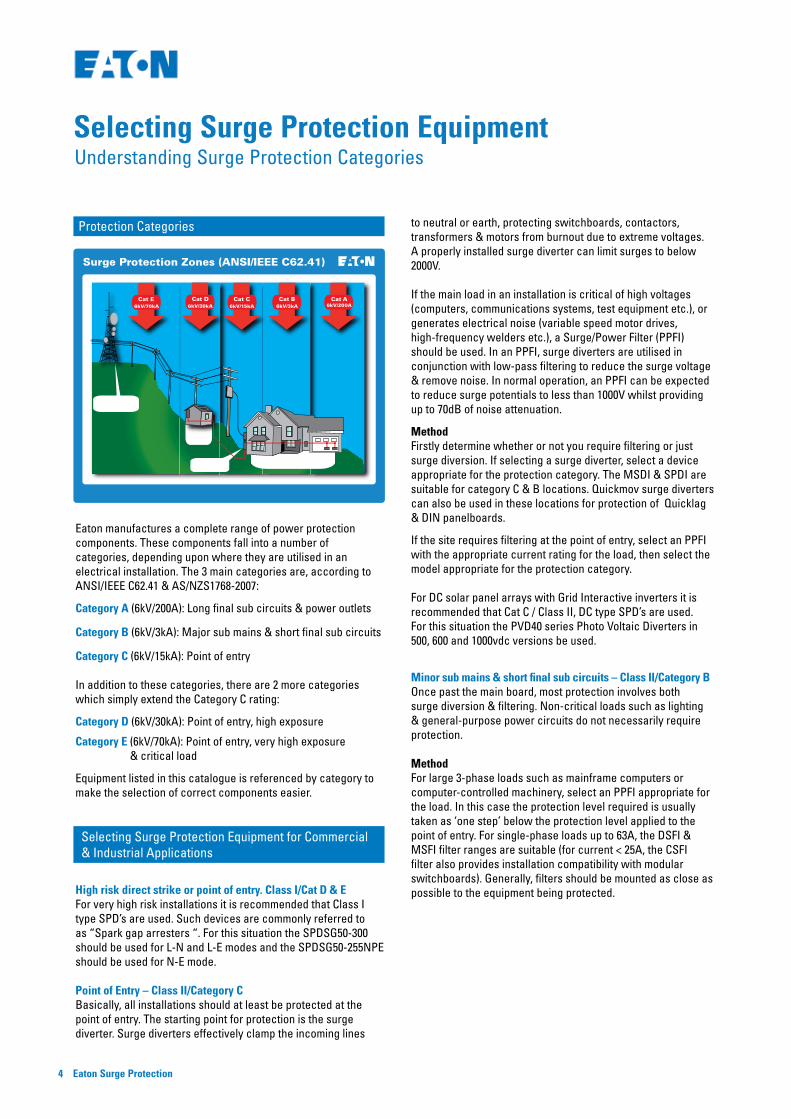
Eaton manufactures a complete range of power protection components. These components fall into a number of categories, depending upon where they are utilised in an electrical installation. The 3 main categories are, according to ANSI/IEEE C62.41 & AS/NZS1768-2007:
Category A (6kV/200A): Long final sub circuits & power outlets
Category B (6kV/3kA): Major sub mains & short final sub circuits
Category C (6kV/15kA): Point of entry
In addition to these categories, there are 2 more categories which simply extend the Category C rating:
Category D (6kV/30kA): Point of entry, high exposure
Category E (6kV/70kA): Point of entry, very high exposure & critical load
Equipment listed in this catalogue is referenced by category to make the selection of correct components easier.
Selecting Surge Protection Equipment for Commercial & Industrial Applications
High risk direct strike or point of entry. Class I/Cat D & E For very high risk installations it is recommended that Class I type SPD’s are used. Such devices are commonly referred to as “Spark gap arresters “. For this situation the SPDSG50-300 should be used for L-N and L-E modes and the SPDSG50-255NPE should be used for N-E mode.
Point of Entry – Class II/Category CBasically, all installations should at least be protected at the point of entry. The starting point for protection is the surge diverter. Surge diverters effectively clamp the incoming lines
to neutral or earth, protecting switchboards, contactors, transformers & motors from burnout due to extreme voltages. A properly installed surge diverter can limit surges to below 2000V.
If the main load in an installation is critical of high voltages (computers, communications systems, test equipment etc.), or generates electrical noise (variable speed motor drives, high-frequency welders etc.), a Surge/Power Filter (PPFI) should be used. In an PPFI, surge diverters are utilised in conjunction with low-pass filtering to reduce the surge voltage & remove noise. In normal operation, an PPFI can be expected to reduce surge potentials to less than 1000V whilst providing up to 70dB of noise attenuation.
MethodFirstly determine whether or not you require filtering or just surge diversion. If selecting a surge diverter, select a device appropriate for the protection category. The MSDI & SPDI are suitable for category C & B locations. Quickmov surge diverters can also be used in these locations for protection of Quicklag & DIN panelboards.
If the site requires filtering at the point of entry, select an PPFI with the appropriate current rating for the load, then select the model appropriate for the protection category.
For DC solar panel arrays with Grid Interactive inverters it is recommended that Cat C / Class II, DC type SPD’s are used. For this situation the PVD40 series Photo Voltaic Diverters in 500, 600 and 1000vdc versions be used.
Minor sub mains & short final sub circuits – Class II/Category BOnce past the main board, most protection involves both surge diversion & filtering. Non-critical loads such as lighting & general-purpose power circuits do not necessarily require protection.
MethodFor large 3-phase loads such as mainframe computers or computer-controlled machinery, select an PPFI appropriate for the load. In this case the protection level required is usually taken as ‘one step’ below the protection level applied to the point of entry. For single-phase loads up to 63A, the DSFI & MSFI filter ranges are suitable (for current < 25A, the CSFI filter also provides installation compatibility with modular switchboards). Generally, filters should be mounted as close as possible to the equipment being protected.
OUT BUILDING
RESIDENTIALBUILDINGSERVICE
ENTRANCE
TELECOM TOWER
6kV/200ACat A
6kV/3kACat B
6kV/15kACat C
6kV/30kACat D
6kV/70kACat E
Surge Protection Zones (ANSI/IEEE C62.41)
Selecting Surge Protection Equipment

Eaton Surge Protection 5
Long Final Sub circuits & Power Outlets - Class III/ Category AWhen protecting final sub circuits & power points there are 2 options. Either fit hard-wired filters to the circuit or use plug-in filters on the equipment to be protected. This choice will be determined by the load (plug-in filters are only rated up to 10A), & whether or not there is space for a plug-in filter adjacent to the equipment. With large computer networks, many administrators prefer not to use plug-in filters as they can be accidentally unplugged by the operator’s foot, causing network problems. For small servers however, a plug-in filter provides extra protection at the computer for ‘insurance’.
MethodFirstly select whether a hard-wired or plug-in filter is to be used. If selecting a hard-wired filter, the DSFI range is suitable for currents up to 32A (for currents < 25A, the CSFI filter also provides installation compatibility with modular switchboards). For plug-in filters, the SSFI series provides high levels of protection with good filtering.
Selecting Surge Protection Equipment for Domestic & Home-office Applications
Point of Entry – Class II/Cat C, BAs with commercial & industrial applications, all installations should at least be protected at the point of entry. Again, this usually involves the use of surge diverters. Surge diverters effectively clamp the incoming lines to neutral or earth, protecting the switchboard & wiring from damage due to extreme voltages.
Surge diverters are a ‘must’ if the building is located in an exposed position or fed by long aerial cables, as in rural installations. If the building is part of a medium or high-density development & is fed by an underground cable, the risk of high-energy surges is quite low. In these cases, a surge diverter may not be necessary.
In most domestic buildings, the main switchboard is the only switchboard & therefore, if it is desired to provide filtered power for critical applications such as computers, office equipment or entertainment systems, this should be done on the main switchboard. Few domestic applications use 3-phase power & those that do usually only use it for heating or air-conditioning. For this reason, only the phase supplying power to critical equipment is actually filtered. The remaining phases are simply fitted with shunt diverters.
MethodFirstly determine whether or not you require filtering or just surge diversion. If selecting a shunt diverter, select a device appropriate for the installation. The SPD3NI, SPD3GI, SPDV60 & SPDT60 are suitable for single & multi-phase installations whilst the SPD120I is ideal for very exposed sites (on hilltops or with long aerial cables).
If the site requires filtering at the point of entry, select a DSFI filter with the appropriate current rating for the load. The DSFI filter is rated at 5-32A (for current < 25A, the CSFI filter also provides installation compatibility with modular switchboards).
Final Sub circuits & Power Outlets – Class III/Cat AWhen protecting final sub circuits & power points there are 2 options. Either fit hard-wired filters to the circuit or use plug-in filters on the equipment to be protected. This choice will be determined by the load (plug-in filters are only rated up to 10A), & whether or not there is space for a plug-in filter adjacent to the equipment. Generally, a plug-in filter, used in conjunction with protection at the switchboard, gives the best protection.
MethodFirstly select whether a hard-wired or plug-in filter is to be used.
If selecting a hard-wired filter, the DSFI is suitable for currents from 5 to 32A (for currents < 25A, the CSFI filter also provides installation compatibility with modular switchboards).
For plug-in filters, the SSFI & POD provides high levels of protection with good filtering. The POD also provides protection for ancillary devices such as phone/fax, network & coaxial cables - ideal for protecting video TV systems in domestic applications.
Note: cable systems are electrically referred to mains neutral which only increases the potential of damage from electrical faults. If high levels of filtering are required such as for home automation or high-end audio visual, or other noise-critical equipment, the sub circuits supplying these systems should be protected at the switchboard by a high level device such as the CSFI.
Selecting Surge Protection for Dataline Applications
For IT & telecommunication applications, dataline network protectors provide further protection against transients which can enter the electrical system through “back-doors”. The EMTJ & ERAK series offer transient protection for single port or multi-port configuration on CAT5 & CAT6 networks. The SF8RM is designed for surge protection in data rack cabinets where space is typically limited.
For twisted pair coms and signalling data line it is recommended that Cat A / Class III type SPD’s are used. For this situation the SPD-DM series diverters in 5, 12, 24 or 48vdc versions be used.

Eaton Surge Protection6
Class I/Category D & E (6kV/30kA)Direct Strike Protection

Eaton Surge Protection 7
Shunt Surge Diverter 3 Phase, 100-400A, 80-240kA
The new SPDSG series diverters are designed as IEC 61643-1, Class I, direct strike, surge diverters to protect high risk installations. Typically known as spark gap devices, these diverters use the latest technology
multiple gap element design to ensure accurate triggering & with no follow current. There are 2 models to choose from. The SPDSG50-300 is suitable for connection across L-N or L-E. The SPDSG50-255NPE is suitable for connection in common mode across N – E. Each have been tested to the stringent requirements of 10/350us waveform standard , commonly known as I imp, & exhibit exceptionally low let through voltage of less than 2.5kV at 50kA.
Specifications• 1 mode protection. N-E, L-E or L-N• 50kA surge suppression rating• Compact modular solution• 2 unit DIN43880 case, 36mm DIN-rail mount
Applications• Direct strike point of entry locations.
Key Features:
Class I/Cat D & E Spark Gap & GDT Diverter Eaton® SPDSG Series
Technical Specifications SPDSG50-300 SPDSG50-255NPE
Technology Encapsulated Spark Gap Encapsulated Gas Arrester
Method of mounting 35mm Din rail 35mm Din rail
Input voltage (Un) 230vac nominal 230vac nominal
Max Continuous Voltage (Mcov) 300vac 255vac
Test classification IEC Class I Class I
Maximum rated surge current – (I imp) 10/350us
50kA 50kA
Max rated surge current – (Imax) 8/20us 140kA 140kA
Residual voltage (Vpl) <2.5KV <2.5KV
Leakage current None None
Response time <100ns <100ns
External disconnector max 160A gL None
Terminations 35mm multi-strand 35mm multi-strand
Insulation resistance > 103 M Ohm > 103 M Ohm
Enclosure material Thermo plastic. UL94-V0 Thermo plastic. UL94-V0
Enclosure rating IP20 IP20
Applicable standards. IEC61643-1:2001 IEC61643-1:2001
Dimensions 35mm (W) x 100mm (H) x 77mm (D) 35mm (W) x 100mm (H) x 77mm (D)
Weight 200 grams 200 grams
Environment -40c to +80c -40c to +80c
Warranty 5 years 5 years
Note: Specifications are subject to change without notice.

Eaton Surge Protection8
Class II/Category C (6kV/15kA)Point of Entry Protection

Eaton Surge Protection 9
Series Power & Noise Filter with Shunt Surge Diverter 3 Phase, 100-400A, 80-240kA
Applications:
• All Power Circuits including "Point-of-Entry"• Telecommunications Systems & Rectifiers• Process & Control Systems & UPS Systems• Computer Systems & Medical Systems• AV circuits for clubs & hotels• All sensitive Electronic Equipment
Key Features:
• Surge suppression & filtering in a single package• Standard Current ratings from 100A to 400A• 1 mode, Multi-Element Series Filter• 2 mode, 3 stage Surge Diverter• Surge suppression ratings from 80kA to 240kA• Provides extensive high frequency & RF filtering• Incorporates a EN certified EMI/RFI filter• Panel-mounted mimic display• Protection Fail Alarm Relay• Enclosed in IP24 painted steel cabinet• 5 Year Warranty
Options:
• Custom configurations• Isolation switches & circuit breakers• Custom cabinets• Chassis Mount versions
The PPFI is designed to provide point-of-entry (Category C) & sub-circuit protection (Category B) against power surges caused by external sources such as lightning strikes & substation switching as well as providing a measure of protection from surge events generated on the secondary side of the filter. An ideal device for all Category locations.
The PPFI is a 3-stage protection system utilising primary & secondary MOV protection in conjunction with a Low-Q LC filter. The unit provides filtering of the line harmonics, noise & RF transmitters with a cut-off frequency of <10kHz & a minimum attenuation of 70dB above 1MHz. Special care has been taken in the design of the filter to minimise ringing caused by light loads, surge diverter operation & inductive load back-EMF.
All models in the PPFI Series are fully enclosed in wall mounting IP24 steel enclosures. A graphical mimic display provides at-a-glance indication of the status of the PPFI with indicators showing correct functions in green & faults in red. The alarm function provides a summary alarm output for protection failure & power failure.
Class II/Cat C & D 3 Phase Premium Power Filter
Eaton® PPFi
Eaton Surge Protection10
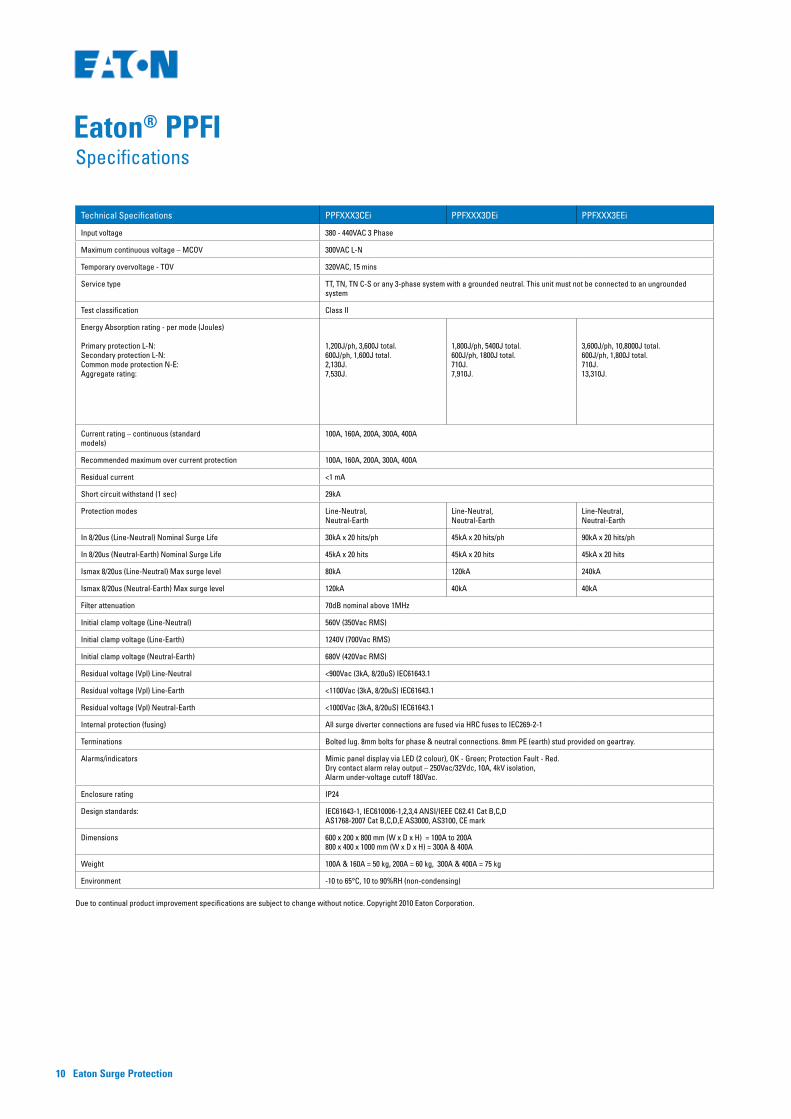
Technical Specifications PPFXXX3CEi PPFXXX3DEi PPFXXX3EEi
Input voltage 380 - 440VAC 3 Phase
Maximum continuous voltage – MCOV 300VAC L-N
Temporary overvoltage - TOV 320VAC, 15 mins
Service type TT, TN, TN C-S or any 3-phase system with a grounded neutral. This unit must not be connected to an ungrounded system
Test classification Class II
Energy Absorption rating - per mode (Joules) Primary protection L-N: Secondary protection L-N: Common mode protection N-E: Aggregate rating:
1,200J/ph, 3,600J total. 600J/ph, 1,600J total.2,130J.7,530J.
1,800J/ph, 5400J total. 600J/ph, 1800J total.710J.7,910J.
3,600J/ph, 10,8000J total. 600J/ph, 1,800J total.710J.13,310J.
Current rating – continuous (standard models)
100A, 160A, 200A, 300A, 400A
Recommended maximum over current protection 100A, 160A, 200A, 300A, 400A
Residual current <1 mA
Short circuit withstand (1 sec) 29kA
Protection modes Line-Neutral, Neutral-Earth
Line-Neutral, Neutral-Earth
Line-Neutral, Neutral-Earth
In 8/20us (Line-Neutral) Nominal Surge Life 30kA x 20 hits/ph 45kA x 20 hits/ph 90kA x 20 hits/ph
In 8/20us (Neutral-Earth) Nominal Surge Life 45kA x 20 hits 45kA x 20 hits 45kA x 20 hits
Ismax 8/20us (Line-Neutral) Max surge level 80kA 120kA 240kA
Ismax 8/20us (Neutral-Earth) Max surge level 120kA 40kA 40kA
Filter attenuation 70dB nominal above 1MHz
Initial clamp voltage (Line-Neutral) 560V (350Vac RMS)
Initial clamp voltage (Line-Earth) 1240V (700Vac RMS)
Initial clamp voltage (Neutral-Earth) 680V (420Vac RMS)
Residual voltage (Vpl) Line-Neutral <900Vac (3kA, 8/20uS) IEC61643.1
Residual voltage (Vpl) Line-Earth <1100Vac (3kA, 8/20uS) IEC61643.1
Residual voltage (Vpl) Neutral-Earth <1000Vac (3kA, 8/20uS) IEC61643.1
Internal protection (fusing) All surge diverter connections are fused via HRC fuses to IEC269-2-1
Terminations Bolted lug. 8mm bolts for phase & neutral connections. 8mm PE (earth) stud provided on geartray.
Alarms/indicators Mimic panel display via LED (2 colour), OK - Green; Protection Fault - Red. Dry contact alarm relay output – 250Vac/32Vdc, 10A, 4kV isolation, Alarm under-voltage cutoff 180Vac.
Enclosure rating IP24
Design standards: IEC61643-1, IEC610006-1,2,3,4 ANSI/IEEE C62.41 Cat B,C,D AS1768-2007 Cat B,C,D,E AS3000, AS3100, CE mark
Dimensions 600 x 200 x 800 mm (W x D x H) = 100A to 200A 800 x 400 x 1000 mm (W x D x H) = 300A & 400A
Weight 100A & 160A = 50 kg, 200A = 60 kg, 300A & 400A = 75 kg
Environment -10 to 65°C, 10 to 90%RH (non-condensing)
Due to continual product improvement specifications are subject to change without notice. Copyright 2010 Eaton Corporation.
Eaton® PPFISpecifications

Eaton Surge Protection 11
Eaton® PPFI
Surge Category
The PPFI is suitable for use in all category locations:
Class II/Cat D
(6kV/30KA) Point of Entry, High Exposure
Class II/Cat C
(6kV/15kA) Point of Entry/ Service Entrance
Class II/Cat B (Special Applications) (6kV/3kA) Major sub mains & short final sub circuits
1 Mode Multi-Element Series Filter2 Mode 2 Stage Surge Diverter
SPFXXX3CEi Block Diagram
Primary MOV
Protection
Secondary MOV
Protection
UL1283 EMF/RFI
Filter Block
Series Blocking Inductor
High FrequencyCapacitor
PowerInput
PowerOutput
Normal Mode
Common Mode Common Mode
Normal Mode
High FrequencyCapacitor
1 Mode Multi-Element Series Filter2 Mode 2 Stage Surge Diverter
SPFXXX3DEi & SPFXXX3EEi Block Diagram
Primary MOV Protection
Secondary MOV Protection
UL1283 EMF/RFI
Filter Block
Series Blocking Inductor
High FrequencyCapacitor
PowerInput
PowerOutput
Normal Mode
Common Mode
High FrequencyCapacitor
Normal Mode
Eaton® PPFIBlock Diagram & Mimic Display

Eaton Surge Protection12
LC3/2/2005550193
S PF i S eries3/2/2005
INPUT/S UPPLY
OUTPUT/LOAD
E Earth StudOn Gear Tray
8mm
MAIN SWBMAIN
E AR THINGPOINT (SWB)
LOAD
Min distanceto ceiling 300mm
Min distanceto floor 600mm
IMPOR TANT NOTE S :1. All phase and neutral connections via 8mm bolts .2. E arth connection via M8 stud, lower right of enclosure.3. R efer to labelling for connection points .4. Always run a separate earth cable, even if the unit is bolted to
the SWB tray.5. Keep input and output cables phys ically separated at all times.
Min. separation dis tance 500mm.6. HR C fuses are preferred to MCBs for connection to main SWB.
S ee Page 2 on installation guide for details .7. Unit is to be located within 3m (cable length) of the main system
E arth and Neutral link for point-of-entry application. G reaterlengths reduce protection.
8.1. E arth wiring: For proper operation of this S PF it is essential thata robust and phys ically short earth connection be made to thes ite earthing point. W ith reference to local wiring standards ,earth cables are usually s ized against a thermal rating,determined by expected fault currents , (5,000 to 25,000 amps).When installing an S PF however, the installer must be awarethat surge currents can exceed 50,000 amps, and thereforeheavier cables are generally required to limit voltage dropsunder surge conditions . To achieve these requirements , theearth cable s ize should be selected to be equal to, or greaterthan, the largest incoming cable into the S PF . This ensures thatvoltage drops on the earth cable are minimised.
8.2 Other wiring: All power-carrying conductors shall be s izedaccording to loca lly-applicable standards . It is recommendedthat the incoming neutral conductor be sized the same as (orlarger than) the phase conducts as it is the primary return forline-neutral surges .
S PF i S urge F ilterConnection Diagram
For S PF1003CE i, S PF1003DE i, S PF1003E E i,S PF150CE i, S PF150DE i, S PF150E E i,S PF200CE i, S PF200DE i, S PF200E E i,S PF250CE i, S PF250DE i, S PF250E E i
Earth
This document is to be us ed in conjunction with
3 - Phas e S urge F ilter Ins tallation Guide(Tvs s Doc#510063)
NL1 L2 L3
L1 L2 L3 N
CMYCM
MY
CY
CM
Y
K
550193_spfi_cn
x_dia_a4.p
df 6/10/2008 12:34:57 PM
Important: Before installing the device, please read & follow the instal-lation & operation instructions.
Connection & Line DiagramEaton® PPFI
1 2 43
A
B
C
D
4321
D
C
B
A Title
noisiveRrebmuNSize
A4
fo teehS 6002-guA-7:etaDFile: C:\tvss engineering\Product_engineering\current\MSF\MSF.ddbDrawn By:
FSEC
LINE IN
NEUTRAL IN
EARTH STUD
LINE OUT
Differential protection and filtering.One phase shown, all phases identical
NO
COM
NC
FROM OTHER PHASES
SPF FILTER LINE DIAGRAM0
1 1JDP
FPRI
L-N protection
N-E protection
L-N protection
NEUTRAL OUT
DIN-ADD
Common-mode protection.
550246
Display Driver
FILTER BLOCK
SPFDisplay PCB
ALARM OUT
CMYCM
MY
CY
CM
Y
K
SPFi_550246.pd
f 6/10/2008 12:21:37 PM

Eaton Surge Protection 13
Shunt Surge Diverter, 3 Phase 200kA
Typical applications:
• All Power Circuits including "Point-of-Entry"• Telecommunications Systems & Rectifiers• Process & Control Systems & UPS Systems• Computer & Medical Systems• Multi-storey buildings• All sensitive Electronic Equipment
Key Features:
• 3 Mode, 2 Stage Surge Diverter• Surge suppression rating of 200kA• Enclosed in IP24 cabinet• LED Bargraph display on each phase• Protection Fail Alarm Relay• 5 Year Warranty
The MSDI surge diverter is designed to provide point-of-entry protection against power surges caused by external sources such as lightning strikes & substation switching. Common-mode protection is available for sites remote from the M.E.N. point including industrial sites & rooftops in multi-storey buildings. An ideal device for all Category locations.
The MSDI surge diverters utilise MOV protection for both differential & common-mode protection. Multiple MOV devices are used in parallel for primary circuit redundancy. The status of protective devices is continuously monitored & displayed using LED bar-graph indicators. All MOV devices are thermally fused & isolated by ceramic fuses.
MSDI unit is provided with an alarm relay. The alarm function provides a summary alarm output for protection degradation as well as power failure. The alarm may be configured to indicate either partial or total protection failure. The level of protection remaining is indicated by LED bar-graph indicators on the front panel. A summary alarm relay contacts provide remote signalling to remote equipment.
Surge Category
The MSDI is suitable for use in category locations:
Class II/Cat D (6kV/30KA) Point of Entry, High Exposure
Class II/Cat C
(6kV/15kA) Point of Entry/ Service Entrance
Class I & II/Cat D & C Three Phase Surge Diverter
Eaton® MSDI
3 Mode 2 Stage Surge Diverter
MSDi Block Diagram (Only 1 phase shown, all phases are identical)
Primary MOV
Protection
PowerInput
PowerOutput
Normal Mode
Common Mode
Common Mode
Secondary MOV
Protection

Eaton Surge Protection14
Technical Specifications MSD200CM60i
Input voltage 200 - 250VAC (380 - 440VAC 3 Phase)
Maximum continuous voltage (MCOV) 320VAC
Temporary overvoltage - TOV 350VAC, 15 mins
Service type TT, TN, TN C-S or any 3-phase system with a grounded neutral
Energy Absorption rating - per mode (Joules) Primary Protection L-N = 3,000J/ph, 9,000J total Common mode protection L-E = 710J/ph, 2,130J total Common mode protection N-E = 2,130J total Aggregate rating 13,260J
Recommended max. overcurrent protection 125A GL HRC fuse
Protection modes Line-Neutral, Line-Earth, Neutral-Earth
In 8/20us (Line-Neutral) Nom. surge life 75kA per phase x 20 times
In 8/20us (Line-Earth) Nom. surge life 15kA per phase x 20 times
In 8/20us (Neutral-Earth) Nom. surge life 45kA x 20 times
Ismax 8/20us (Line-Neutral) Max. surge life 200kA
Ismax 8/20us (Line-Earth) Max. surge life 40kA
Ismax 8/20us (Neutral-Earth) Max. surge life 120kA
Initial clamp voltage (Line-Neutral) 560V (350Vac RMS)
Initial clamp voltage (Line-Earth) 680V (420Vac RMS)
Initial clamp voltage (Neutral-Earth) 680V (420Vac RMS)
Internal protection (fusing) All surge diverter connections are fused via HRC fuses to IEC269-2-1
Alarms/indicators Bargraph display for protection remaining, dry contact alarm relay output – 250Vac/32Vdc, 10A, 4kV isolation, Alarm under-voltage cutoff 180Vac.
Enclosure rating IP24
Design Standards: IEC61643-1, IEC610006-1,2,3,4 ANSI/IEEE C62.41 Cat B,C,D,E AS1768-2007 Cat B,C,D,E AS3000, AS3100, CE mark
Dimensions & Weight 370 x 160 x 560 mm (W x D x H), 14kg
Environment -10 to 65°C, 10 to 90%RH (non-condensing)
Eaton® MSDI
LC2/23/2005550192
MSDi S eries2/23/2005
INPUT
E E AR TH S TUDON CAS E
8mm
MAINE AR THING
POINT (SWB )
MSDi S urge DiverterConnection Diagram
This document is to be us ed in conjunction with
MSDi S urge Diverter Ins tallation Guide(Tvs s Doc#510065)
NEUTR AL LINKOR
M.E .N.
L1
L2
L3
MAIN SWB
FUSE
< 3m line distance
Min distanceto floor 600mm
Min distanceto ceiling 300mm
TO LOADS
IMPOR TANT NOTE S :1. All phase and neutral connections via 8mm bolts .2. E arth connection via M8 stud, lower right of enclosure.3. R efer to labelling for connection points .4. Always run a separate earth cable, even if the unit is bolted to
the SWB tray.5. Keep input and output cables phys ically separated at all times.
Min. separation dis tance 500mm.6. HR C fuses are preferred to MCBs for connection to main SWB.
S ee Page 2 on installation guide for details .7. Unit is to be located within 3m (cable length) of the main system
E arth and Neutral link for point-of-entry application. G reaterlengths reduce protection.
8.1. E arth wiring: For proper operation of this MSD it is essential thata robust and phys ically short earth connection be made to thes ite earthing point. W ith reference to local wiring standards ,earth cables are usually s ized against a thermal rating,determined by expected fault currents , (5,000 to 25,000 amps).When installing an MSD however, the installer must be awarethat surge currents can exceed 50,000 amps, and thereforeheavier cables are generally required to limit voltage dropsunder surge conditions . To achieve these requirements , theearth cable s ize should be selected to be equal to, or greaterthan, the largest incoming cable into the MSD. This ensures thatvoltage drops on the earth cable are minimised.
8.2 Other wiring: All power-carrying conductors shall be sizedaccording to loca lly-applicable standards . It is recommendedthat the incoming neutral conductor be s ized the same as (orlarger than) the phase conducts as it is the primary return forline-neutral surges .
L3 L2 L1 N
CMYCM
MY
CY
CM
Y
K
550192_msd
i_cnx_d
ia_a4.pd
f 6/10/2008 1:30:27 PM
Important: Before installing the device, please read & follow the installation & operation instructions.
1 2 43
A
B
C
D
4321
D
C
B
A Title
noisiveRrebmuNSize
A4
fo teehS 6002-guA-7:etaDFile: C:\tvss engineering\Product_engineering\current\MSF\MSF.ddbDrawn By:
LINE
NEUTRAL
EARTH STUD
Differential protection.One phase shown, all phases identical
NO
COM
NC
FROM OTHER PHASES
MSD LINE DIAGRAM0
1 1JDP
FPRI
L-N protection
N-E protection L-E protection
Protection alarm
Common-mode protection.One phase shown, all phases identical
550250
CMYCM
MY
CY
CM
Y
K
MSD
i_550250.pd
f 6/10/2008 1:33:06 PM
Eaton® MSDISpecifications
Connection & Line Diagram
Due to continual product improvement specifications are subject to change without notice. Copyright 2010 Eaton Corporation.

Eaton Surge Protection 15
Shunt Surge Diverter, 1 & 3 Phase, 40kA & 100kA
Key Features:
• Surge ratings starting from 40kA up to 100kA (8/20uS) • DIN43880 profile IP20 enclosure allows compatibility with most common switchboards• Versatile mounting clips offer the option of DIN rail or surface mount with ease• Clear & concise protection status indicators &
a dry-contact alarm• Extended voltage range to suit most common power distribution systems
Eaton's SPDI surge diverters provide the ultimate solution for surge protection in single & multi-phase systems. Whether the application involves residential homes, telecommunication facilities, hospitals, schools or heavy industrial plants, the SPDI surge diverters provide protection against the damaging effects of lightning, utility switching, switching electric motors & more. SPDI surge diverters can be installed as point-of-entry or sub-board protection & are connected in parallel with the power circuit via separate protection HRC fuses. These devices are ideal for Category C & B locations.
The SPD120I is designed to protect single-phase power systems against surges & spikes caused by lightning strikes & other electrical sources. The unit is intended for point-of-entry or main board protection in medium to high exposed locations. SPD120I are easily configured for L-N or L-E protection for installations adjacent or remote from the M.E.N. link, which means it can provide protection for commercial buildings to rural sites.
1 Mode (L-N) 1 Stage Diverter
SPD120i Block Diagram
MOV Protection
PowerInput
PowerOutput
Normal Mode
Class I & II/Cat D, C & B Din Rail Mounted Surge Diverters
Eaton® SPDI Series
Class I/Cat D

Eaton Surge Protection16
The SPD3NI is designed to protect 3-phase power systems against damage from surges & spikes caused by lightning & other electrical sources. The unit is intended for point-of-entry or sub-board protection in low to medium exposed locations adjacent to the M.E.N. link. For protection in locations remote from the M.E.N. link use a SPD3GI Gas Arrestor model.
2 Mode 1 Stage Surge Diverter
SPD3Ni Block Diagram
L1 MOV Protection
L2 MOV Protection
L3 MOV Protection
PowerInput
PowerOutput
NormalMode
Normal Mode
Common Mode
Normal Mode
L1
L2
L3
N
E
L1
L2
L3
N
E
Surge Category
The SPDI is suitable for use in category locations:
Class II/Cat D
(6kV/30KA) Point of Entry, High Exposure (SPD120I Only)
Class II/Cat C
(6kV/15kA) Point of Entry/ Service Entrance
Class II/Cat B (6kV/3kA) Major sub mains & short final sub circuits
2 Mode 1 Stage Surge Diverter
SPD3Gi Block Diagram
L1 MOV Protection
L2 MOV Protection
L3 MOV Protection
PowerInput
PowerOutput
Common Mode
Common Mode
Common Mode
Common Mode
L1
L2
L3
N
E
L1
L2
L3
N
E
Applications:
• Ideal for Point of Entry or Sub-board Protection• Telecommunication Systems & Rectifiers• Process & Control Systems• Computer Systems• Medical Systems• All Sensitive Electronic Equipment
Class II/Cat C & B Din Rail Mounted Surge Diverters
Eaton® SPDI Series
Class II/Cat C & B

Eaton Surge Protection 17
Technical Specifications SPD120I SPD3NI SPD3GI
Input voltage 220-277VAC (380-480V) 40-70 Hz
220-277VAC (380-480V) 40-70 Hz
220-300VAC (380-520V) 40-70 Hz
Maximum continuous operating voltage (MCOV) 320VAC 350VAC
Temporary overvoltage - TOV 350VAC, 15 mins 420VAC, 15 mins
Service Type TN-C & TN C-S (3-wire with grounded neutral) TN-S & TT (3-wire with grounded neutral)
Test Classification (IEC61643-1) Class II
Initial clamp voltage 560V 680V
Maximum rated surge current - Ismax 8/20us 100kA 40kA / Phase
Nominal surge current - In 8/20us 50kA 20kA / Phase
Residual voltage (Vpl) @ 3kA, 8/20us 1.0kV <1.2kV L-N, 900V N-E <1.2kV L-N, 1.4kV N-E
Residual voltage (Vpl) @ 40kA, 8/20us 1.65kV <2.1kV L-N, 1.46kV N-E <2.1kV L-N, 2.45kV N-E
Energy absorption (2ms) 2130 Joules 3640 Joules
Nominal surge lifetime (In) 50kA (8/20us), 20 times 20kA (8/20us), 20 times
Recommended maximum over- current protection gG/gL HRC fuses, 1 per phase, 125A maximum
Terminations Power terminals 16mm2, Alarm terminals 1.5mm2
Alarms/Indicators 5 indicators, dry contact alarm relay - 250VAC/32VDC, 5A
Design standards IEC61643-1, IEC610006, ANSI/EEE C62.41, AS1768-2007, AS3100, CE mark
Dimensions & Weight (DIN43880) 70 x 68 x 90 mm (WxDxH), 200g
Important: Before installing the device, please read & follow the installation & operating instructions.
Eaton® SPDISpecifications
Connection Diagrams
Due to continual product improvement specifications are subject to change without notice. Copyright 2010 Eaton Corporation.
SPD120I SPD3NI SPD3GI
L-N ConnectionL-E Connection

Eaton Surge Protection18
Key Features:
• 1 mode plug-in protection • 60kA 8/20uS maximum surge rating• Compact solution for primary protection• DIN43880 case, 35mm DIN-rail• Removable dry-contact alarm connection• Thermally protected
Applications:
• Mains point-of-entry / Sub-board • Factories / Workshops• Small Offices / Residential homes
Surge Category
The SPDV60 & SPDT60 is suitable for use in category locations:
Class II/Cat C(6kV/15kA) Point of Entry/ Service Entrance
Class II/Cat B(6kV/3kA) Major sub mains & short final sub circuits
Shunt Surge Diverter, 1 Pole 60kA
The new SPDV60-300 & SPDT60-255 single pole DIN surge diverters offer 60kA of surge suppression, making them suitable for either main or sub-board protection. The compact modular design allows the units to be easily installed in new or retrofitting existing installations. The units feature a plug-in module that may be replaced without rewiring in the event of a fault.
The SPDV60-300 utilises the latest thermal MOV technology, making it suitable for point-of-entry protection in main switchboards & can be used in conjunction with an SPDT60-225 Gas Arrestor for protection on distribution boards remote from the M.E.N. point. Both models come as standard with mechanical flag status indication & a dry contact alarm for remote status monitoring.
1 Mode (L-N) 1 Stage Diverter
SPDV60 Block Diagram
MOV Protection
PowerInput
PowerOutput
Normal Mode
1 Mode (N-E) 1 Stage Diverter
SPDT60 Block Diagram
GDTProtection
PowerInput
PowerOutput
Common Mode
Class II/Cat C & B Modular Single Pole DIN Surge Diverters
Eaton® SPDV60 & SPDT60

Eaton Surge Protection 19
Important: Before installing the device, please read & follow the installation & operating instructions.
Technical Specifications SPDV60-300 SPDT60-255Input voltage 220-250VAC (380-480V) 40-70Hz Neutral - Earth connection only. System voltage 220-
250VAC (380-440V)
Maximum Continuous voltage - MCOV 300VAC 255VAC (no conduction under load fault conditions)
Shunt Technology MOV GDT
Service type TN-C & TN C-S (3-Phase with grounded neutral)
Single & 3-Phase with remotely grounded neutral
Test Classification (IEC61643-1) Class II
Supply Current <10mA
Initial clamp voltage 470V N/A
Initial spark over voltage N/A 600V
Maximum rated surge current - Ismax 8/20us 60kA
Nominal surge current - in 8/20us 30kA 40kA
Residual voltage (Vpl) @ 3kA, 8/20us 1.0kV N/A
Residual voltage (Vpl) @ Ismax, 8/20us 1.4kV 1.8kV
Energy absorption (2ms) 2130 Joules N/A
Nominal surge lifetime (In) 30kA (8/20us), 20 times 40kA (8/20us), 20 times
Internal protection MOV thermal disconnect device Thermal disconnector
Recommended maximum over-current protection gG/gL HRC fuses, 1 per phase, 160A max None
Terminations Power terminals 16mm2, Alarm terminals 1.5mm2
Alarms / indicators Flag indicator, dry contact alarm relay - 250VAC/24VDC, 2A
Design Standards: IEC61643-1, IEC610006, ANSI/IEEE C62.41, AS1768-2007, AS3100, CE mark
Dimensions & Weight (DIN43880) 17 x 68 x 90 mm (not incl relay), 100g
Eaton® SPDV60 & SPDT60Specifications
Connection Diagrams
Due to continual product improvement specifications are subject to change without notice. Copyright 2010 Eaton Corporation.
SPDV60-300 SPDT60-255

Eaton Surge Protection20
Key Features:
• Surge rating 30kA Inom & 60kA Imax • Integrated Surge Protection solution• In-built HRC fusing• Dual Barrier Flame Retardant Housing• Fail Safe Status Indicator• Protection for MEN & non-MEN applications • Compatibility with Quicklag™ accessories• Designed in Australia
Shunt Surge Diverter, 1 Pole 60kA
Quickmov™ is Australia's first fully integrated Surge Protection Device (SPD), designed to protect single & multi-phase electrical distribution systems against the damaging effects of voltage spikes & surges.
The new Quickmov™ SPD plugs straight into a Quicklag™ loadcentre, connecting to the chassis busbar for the lowest source impedance. Its integrated HRC fuse enables the Quickmov™ to be connected directly to the neutral bar, providing the shortest possible cable length for superior protection of the entire loadcentre. The advanced MOV technology is housed in a dual barrier flame retardant case to provide optimum surge protection performance without compromising safety & reliability.
The Quicklag™ range of mounting accessories compliments the Quickmov™, extending its features & benefits to many applications. Its integrated protection reduces the amount of extra components required to carry out a typical installation, saving valuable space & installation time. With a 60kA (MOV Imax) surge suppression rating, Quickmov™ is ideal for primary protection in main switchboards & can be used in conjunction with an Eaton SPD50NGI Neutral-Earth arrestor for distribution boards remote from the M.E.N. point.
Surge Category
The Quickmov™ is suitable for use in category locations:
Class II Cat C (6kV/15kA) Point of Entry/ Service Entrance
Class II Cat B (6kV/3kA) Major sub mains & short final sub circuits
1 Mode (L-N) 1 Stage Diverter
Quickmov Block Diagram
MOV Protection
PowerInput
PowerOutput
Normal Mode
HRC Fuse
MOV
ThermalFuse
Element
Class II/Cat C & B Integrated Quicklag Protection Device
Eaton Quickmov™

Eaton Surge Protection 21
Important: Before installing the device, please read & follow the installation & operating instructions.
Technical Specifications SPDQM1
Protection Mode Single Mode - connected L-N
Service type TNC, TN C-S (for TNS add 1 x SPD50NGI protector)
System voltage - Un 220 - 250VAC (380 - 440VAC 3 Ph) 50/60 Hz
Test Classification Class II (IEC 61643-1), Category C3 (ANSI/IEEE C62.41)
Maximum Continuous Over Voltage (MCOV - Uc) 300VAC
Temporary Over Voltage (TOV) (5s) 330VAC
External disconnector requirements None. In-built 100AgL/50kA HRC fuse
Surge current rating In (20 times) 30kA (8/20us)
Surge current rating Ismax (2 times) 60kA (Imax MOV rating, 8/20us)
Residual voltage (Vpl) @ 3kA 1.1kV (cable trimmed to 250mm)
Residual voltage (Vpl) @ In 1.8kV (device only)
Connections Quicklag™ terminal for phase connection. 6mm2 cable (black) for Neutral connection (500mm length)
Dimensions & Weight 25 x 71 x 93 mm (WxDxH), 310g
Eaton Quickmov™Specifications
Connection Diagram
Due to continual product improvement specifications are subject to change without notice. Copyright 2010 Eaton Corporation.

Eaton Surge Protection22
Shunt Surge Diverter, 60kA The new PVD series diverters are designed to protect home & industrial solar panel arrays commonly used in grid interactive power solutions in the 1.5kW to 10kW range. These systems commonly use voltages between 500-1000VDC from the solar panels.
Class II/Cat C & D Photovoltaic Diverters
Eaton PVD40 Series
Technical Specifications PVD40-500-V-C PVD40-600-V-C PVD40-1000-V-CD
Nominal Voltage Un 500VDC 600VDC 1000VDC
Voltage Uc 530VDC 620VDC 1060VDC
Nominal Discharge Current ( 8/20us, kA ) Inom. 20 20 20
Max Discharge Current ( 8/20us, kA ) Imax. 40 40 40
Nominal current (ma) IL 10 10 10
Residual voltage (Vpl) @ Inom 20kA, 8/20us 1.6kV 2.0kV 3.2kV
Test classification Class II Class II Class II
External disconnector ( if required ) 125A Gg/Gl fuse 125A Gg/Gl fuse 125A Gg/Gl fuse
Internal protection MOV thermal disconnect MOV thermal disconnect MOV thermal disconnect
Alarm & indicators Red flag indicator on moduleAlarm relay contact. 250vac/24vdc, 2A
Red flag indicator on moduleAlarm relay contact. 250vac/24vdc, 2A
Red flag indicator on moduleAlarm relay contact. 250vac/24vdc, 2A
Terminations Main terminals 25mmAlarm terminals 1.5mm
Main terminals 25mmAlarm terminals 1.5mm
Main terminals 25mmAlarm terminals 1.5mm
Degree of protection ( IP rating ).
20 20 20
Mounting Din rail Din rail Din rail
Enclosure material UL94 V0 UL94 V0 UL94 V0
Environment temperature ( C ) -10 to 60c, 0-90% RH -10 to 60c, 0-90% RH -10 to 60c, 0-90% RH
Applicable standards IEC61643-1:2000UL1449 ed3
IEC61643-1:2000UL1449 ed3
IEC61643-1:2000UL1449 ed3
Weight 180g 180g 240g
Dimensions 90mm (H) x 36mm (W) x 68mm (D) excluding alarm connectors
90mm (H) x 36mm (W) x 68mm (D) excluding alarm connectors
90mm (H) x 54mm (W) x 68mm (D) excluding alarm connectors
Warranty 12 months 12 months 12 months
The PVD series diverters are designed to protect the DC input side of grid interactive inverters from harmful transients that can appear on the output of solar arrays, especially where they are located on roof or other high infrastructure locations. These units can be combined with existing SPDV60 series diverters on the AC Input/Output side of the inverter to provide complete protection from surges & thus increasing the life of a grid interactive solution investment. IEC61643-1 & UL1449 ed3 compliant. Available in 3 models to suit nominal 500, 600 & 1000VDC systems.
Key Features
• 2 mode plug in protection• 40kA surge suppression rating• Compact modular solution• 2 & 3 unit DIN43880 case, 36 & 54mm DIN-rail mount
Applications
• Standalone & Grid Interactive Solar arrays.

Eaton Surge Protection 23
In microseconds a power surge can do major damage to sensitive equipment and data. It can come from anywhere, and like a bullet, you only know it has been by the destruction leftbehind. That's why surge protection is so critical. And why Eaton builds so much
quality into our full line of Powerware surge protection products. Eaton has a world beating reputation for Power Quality and a full range of surge protection solutions, covering every eventuality.
Faster than a speeding bullet
Much faster.

Eaton Surge Protection24
Class II/Category B (6kV/3kA)Secondary Point Protection

Eaton Surge Protection 25
Series Filter with Shunt Surge Diverter, 1 & 3 Phase, 40A, 63A & 160kA
The MSFI is designed to provide point-of-entry protection against power surges caused by external sources such as lightning strikes & substation switching as well as providing a measure of protection from surge events generated on the secondary side of the filter. An ideal device for Category B & some Category C locations.
The MSFI is a 3-stage protection unit utilising primary & secondary MOV protection in conjunction with a Low-Q LC filter. The unit provides filtering of the line harmonics, noise & RF transmitters with a cut-off frequency of <10kHz & a minimum attenuation of 40dB above 1MHz. Special care has been taken in the design of the filter to minimise ringing caused by light loads, surge diverter operation & inductive load back-EMF.
Surge Category
The MSFI is suitable for use in category locations:
Class II/Cat C
(6kV/15kA) Point of En-try/ Service Entrance
Class II/Cat B
(6kV/3kA) Major sub mains & short final sub circuits
1 Mode 2 Element Series Filter3 Mode 2 Stage Surge Diverter
MSFi Block Diagram (Single Phase shown)
Primary MOV
Protection
Secondary MOV
Protection
Series Blocking Inductor
High FrequencyCapacitor
PowerInput
PowerOutput
Normal Mode
Common Mode
Normal Mode
Class II/Cat C & B 1 & 3 Phase 40-63A Series Surge Filters
Powerware® MSFI
Typical applications:
• All Power Circuits including "Point-of-Entry"• Telecommunications Systems & Rectifiers• Process & Control Systems & UPS Systems• Computer Systems & Medical Systems• All sensitive Electronic Equipment
Key Features:
• Surge suppression & filtering in a single package• 1 mode, 2 Element Series Filter• 3 Mode, 2 Stage Surge Diverter• Surge suppression rating of 160kA• Power & Protection status indicators• Protection Fail Alarm Relay• 5 Year Warranty

Eaton Surge Protection26
Technical Specifications MSF401CCMI MSF631CCMI MSF403CCMI MSF633CCMI
Input voltage 220 – 254VAC 1 Phase 380 - 440VAC 3 Phase
Maximum continuous voltage - MCOV 320VAC
Temporary overvoltage - TOV 350VAC, 15 mins
Service type TT, TN, TN C-S or any system with a grounded neutral. This unit must not be connected to an ungrounded system
Test Classification Class II (IEC 61643-1), Category C3 (ANSI/IEEE C62.41)
Energy Absorption rating - per mode (joules) Primary protection L-N = 2,400J/ph, Three Phase unit = 7,200J total Secondary protection L-N = 600J/ph, Three Phase unit = 1,800J total Common mode protection L-N & N-E = 1,420J, Three Phase unit = 4,280J total Aggregate rating 4,420J (single phase units), 13,260J (three phase units)
Current rating - continuous 40A 63A 40A 63A
Recommended maximum over current protection 40A 63A 40A 63A
Short circuit withstand (1 sec) 29kA
Protection modes Line-Neutral, Line-Earth, Neutral-Earth
In 8/20us (Line-Neutral) Nom. surge life 60kA x 20 hits 60kA x 20 hits/ph
In 8/20us (Line-Earth) Nom. surge life 15kA x 20 hits 15kA x 20 hits/ph
In 8/20us (Neutral-Earth) Nom. surge life 15kA x 20 hits 45kA x 20 hits
Ismax 8/20us (Line-Neutral) Max surge level 160kA 160kA/ph
Ismax 8/20us (Line-Earth) Max surge level 40kA 40kA/ph
Ismax 8/20us (Neutral-Earth) Max surge level 40kA 120kA/ph
Filter attenuation 40dB nominal above 1MHz
Initial clamp voltage (Line-Neutral) 560V (350Vac RMS)
Initial clamp voltage (Line-Earth) 680V (420Vac RMS)
Initial clamp voltage (Neutral-Earth) 680V (420Vac RMS)
Internal protection (fusing) All surge diverter connections are fused via HRC fuses to IEC269-2-1
Alarms/indicators 2 LED display, dry contact alarm relay output – 250Vac/32Vdc, 10A, 4kV isolation, Alarm under-voltage cutoff 180Vac.
Enclosure rating IP24
Design Standards: IEC61643-1, IEC610006-1,2,3,4 ANSI/IEEE C62.41 Cat B,C,D,E AS1768-2007 Cat B,C,D,E AS3000,AS3100, CE mark
Dimensions 210 x 160 x 560 mm (W x D x H) 370 x 160 x 560 mm (W x D x H)
Weight 9kg 14Kg
Environment -10 to 65°C, 10 to 90%RH (non-condensing)
LC2/23/2005550190
3-Phase MS F i S eries2/23/2005
INPUT
OUTPUT
E Earth StudOn Case8mm
MAIN SWBMAIN
E AR THINGPOINT (SWB)
LOAD
Min distanceto ceiling 300mm
Min distanceto floor 600mm
3-Phas e MS F i S urge F ilterConnection Diagram
For MS F323CCMi, MS F403CCMi, MS F633CCMi
E arth
This document is to be us ed in conjunction with
3-Phas e S urge F ilter Ins tallation Guide(Tvs s Doc#510063)
N L1 L2 L3
N L1 L2 L3
IMPOR TANT NOTE S :1. All phase and neutral connections via 8mm bolts .2. E arth connection via M8 stud, lower right of enclosure.3. R efer to labelling for connection points .4. Always run a separate earth cable, even if the unit is bolted to
the SWB tray.5. Keep input and output cables phys ically separated at all times.
Min. separation dis tance 500mm.6. HR C fuses are preferred to MCBs for connection to main SWB.
S ee Page 2 on installation guide for details .7. Unit is to be located within 3m (cable length) of the main system
E arth and Neutral link for point-of-entry application. G reaterlengths reduce protection.
8.1. E arth wiring: For proper operation of this MS F it is essential thata robust and phys ically short earth connection be made to thes ite earthing point. W ith reference to local wiring standards ,earth cables are usually s ized against a thermal rating,determined by expected fault currents , (5,000 to 25,000 amps).When installing an MS F however, the installer must be awarethat surge currents can exceed 50,000 amps, and thereforeheavier cables are generally required to limit voltage dropsunder surge conditions . To achieve these requirements , theearth cable s ize should be selected to be equal to, or greaterthan, the largest incoming cable into the MSF . This ensures thatvoltage drops on the earth cable are minimised.
8.2 Other wiring: All power-carrying conductors shall be s izedaccording to locally-applicable standards . It is recommendedthat the incoming neutral conductor be sized the same as (orlarger than) the phase conducts as it is the primary return forline-neutral surges .
LC2/25/2005550191
S ingle Phase MS F i S eries2/25/2005
INPUT
OUTPUT
E Earth StudOn Case8mm
MAIN SWBMAIN
E AR THINGPOINT (SWB)
LOAD
Min distanceto ceiling 300mm
Min distanceto floor 600mm
S ingle Phas e MS F i S urge F ilterConnection Diagram
For MS F321CCMi, MS F401CCMi, MS F631CCMi
E arth
This document is to be us ed in conjunction with
S ingle Phas e S urge F ilter Ins tallation Guide(Tvs s Doc#510064)
N L
N L
IMPOR TANT NOTE S :1. All phase and neutral connections via 8mm bolts .2. E arth connection via M8 stud, lower right of enclosure.3. R efer to labelling for connection points .4. Always run a separate earth cable, even if the unit is bolted to
the SWB tray.5. Keep input and output cables phys ically separated at all times.
Min. separation dis tance 500mm.6. HR C fuses are preferred to MCBs for connection to main SWB.
S ee Page 2 on installation guide for details .7. Unit is to be located within 3m (cable length) of the main system
E arth and Neutral link for point-of-entry application. G reaterlengths reduce protection.
8.1. E arth wiring: For proper operation of this MS F it is essential thata robust and phys ically short earth connection be made to thes ite earthing point. W ith reference to local wiring standards ,earth cables are usually s ized against a thermal rating,determined by expected fault currents , (5,000 to 25,000 amps).When installing an MS F however, the installer must be awarethat surge currents can exceed 50,000 amps, and thereforeheavier cables are generally required to limit voltage dropsunder surge conditions . To achieve these requirements , theearth cable s ize should be selected to be equal to, or greaterthan, the largest incoming cable into the MSF . This ensures thatvoltage drops on the earth cable are minimised.
8.2 Other wiring: All power-carrying conductors shall be s izedaccording to locally-applicable standards . It is recommendedthat the incoming neutral conductor be sized the same as (orlarger than) the phase conducts as it is the primary return forline-neutral surges .
Important: Before installing the device, please read & follow the installation & operating instructions.
Single Phase Connection
3 Phase Connection
Eaton® MSFISpecifications
Connection Diagrams
Due to continual product improvement specifications are subject to change without notice. Copyright 2010 Eaton Corporation.

Eaton Surge Protection 27
Applications:
• Secondary power circuits/Sub-boards• UPS Systems & Rectifiers• Telecommunications Systems & Rectifiers• Process & Control Systems & UPS's up to 6kVA• Computer Systems & Medical Systems• AV circuits for clubs & hotels• All sensitive Electronic Equipment
Key Features:
• Surge suppression & filtering in a single package• Modular design• Enclosed in IP20 painted steel housing• Protection Fail Alarm Relay• 3 mode, 3 Stage Protection• 5 Year Warranty
The DSFI is designed to provide secondary protection against power surges caused by external sources such as lightning strikes & substation switching as well as providing a measure of protection from surge events generated on the secondary side of the filter.
The DSFI is a 3-stage protection unit utilising primary & secondary MOV protection in conjunction with a 2-stage Low-Q LC filter (i.e. 2 inductive coils) using separate differential mode & common mode circuits. The unit providesfiltering of the line harmonics, noise & RF transmitters with a cut-off frequency of <1.5kHz & a minimum attenuation of >55dB to 10MHz.
Secondary MOV protection (in all 3 modes) is located after the inductive coils, to provide further surge reduction & to protect against load-generated surges. An ideal device for Category B & A locations.
NormalMode
2 Mode 5 Element Series Filter3 Mode 2 Stage Surge Diverter
DSFi Block Diagram
Primary MOV
Protection
Secondary MOV
Protection
Series Blocking inductor
Series Blocking Inductors
High FrequencyCapacitor
High FrequencyCapacitor
PowerInput
PowerOutput
Normal Mode
Common Mode
Normal Mode
Common Mode
Surge Category
The DSFI is suitable for use in category locations:
Class II/Cat B (6kV/3kA) Major sub mains & short final sub circuits
Class II/Cat A
(6kV/200A) Long final sub circuits & power outlets
Class II/Cat B & A Single Phase High Performance Surge Filter
Eaton® DSFI
Series Filter with Shunt Surge Diverter, 1 Phase 5-32A, 40kA Primary

Eaton Surge Protection28
Technical Specifications DSFIInput voltage 200-250VAC 1 Phase
Service type TT, TN, TN C-S or any single-phase system with a grounded neutral.
Test Classification Class III (IEC 61643-1), Category A & B (ANSI/IEEE C62.41)
Energy Absorption rating - per mode (joules) Primary Protection L-N = 740 J Primary common mode protection L-E & N-E = 780 J Secondary protection L-N = 225J Secondary common mode protection L-E & N-E = 480J Aggregate rating = 2,225J
Current rating – continuous 5 - 32A
Recommended max. overcurrent protection 32A (C curve MCCB)
Short circuit withstand (1 sec) Suitable for use with a 6kAIC C Curve MCB
Protection modes Line-Neutral, Line-Earth, Neutral-Earth
In 8/20us (Line-Neutral) 15kA x 20 hits
In 8/20us (Line-Earth) 10kA x 20 hits
In 8/20us (Neutral-Earth) 10kA x 20 hits
Ismax 8/20us (Line-Neutral) 40kA
Ismax 8/20us (Line-Earth) 25kA
Ismax 8/20us (Neutral-Earth) 25kA
Filter attenuation >55dB to 10MHz
Internal protection (fusing) Thermal
Terminations 10mm2 PCB Mounted Terminals
Alarms/indicators 2 LED display, Power OK & Protection OK LEDs, Dry contact alarm relay output – 250Vac/32Vdc, 5A, 5kV isolation, Alarm under-voltage cutoff 180Vac
Enclosure rating IP20
Design Standards: IEC61643-1, IEC610006-1,2,3,4 ANSI/IEEE C62.41 Cat B,C,D,E AS1768-2007 Cat B,C,D,E AS3000,AS3100, CE mark
Dimensions & Weight 140 x 50 x 270 mm (W x D x H), 1.5kg
Environment -10 to 65°C, 10 to 90%RH (non-condensing)
1 2 43
A
B
C
D
4321
D
C
B
A Title
noisiveRrebmuNSize
A4
fo teehS 6002-guA-7:etaDFile: C:\tvss engineering\Product_engineering\current\MSF\MSF.ddbDrawn By:
LINE IN
NEUTRAL IN
EARTH STUD
LINE OUT
Differential filtering
DSFi FILTER LINE DIAGRAM
01 1
JDP
L-N protection
N-E protection L-E protection
L-N protection
NEUTRAL OUT
Common-mode protection.
550248
N-E protectionL-E protection
Thermal fuse
CM TX
Indicator/Alarm
EARTH STUD
INDUCTOR
Common mode filtering
Important: Before installing the device, please read & follow the installation & operating instructions.
Eaton® DSFISpecifications
Connection & Line Diagram
Due to continual product improvement specifications are subject to change without notice. Copyright 2010 Eaton Corporation.
Eaton Surge Protection 29
Series Filter with Shunt Surge Diverter, 1 Phase 3-25A, 25kA Primary
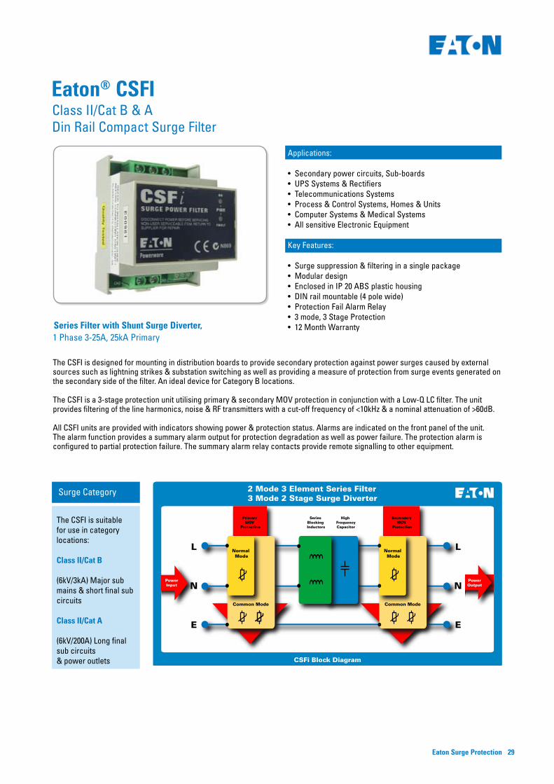
The CSFI is designed for mounting in distribution boards to provide secondary protection against power surges caused by external sources such as lightning strikes & substation switching as well as providing a measure of protection from surge events generated on the secondary side of the filter. An ideal device for Category B locations.
The CSFI is a 3-stage protection unit utilising primary & secondary MOV protection in conjunction with a Low-Q LC filter. The unit provides filtering of the line harmonics, noise & RF transmitters with a cut-off frequency of <10kHz & a nominal attenuation of >60dB.
All CSFI units are provided with indicators showing power & protection status. Alarms are indicated on the front panel of the unit. The alarm function provides a summary alarm output for protection degradation as well as power failure. The protection alarm is configured to partial protection failure. The summary alarm relay contacts provide remote signalling to other equipment.
2 Mode 3 Element Series Filter3 Mode 2 Stage Surge Diverter
CSFi Block Diagram
Primary MOV
Protection
Secondary MOV
Protection
Series Blocking Inductors
High FrequencyCapacitor
PowerInput
PowerOutput
Normal Mode
Common Mode
Normal Mode
Common Mode
Surge Category
The CSFI is suitable for use in category locations:
Class II/Cat B
(6kV/3kA) Major sub mains & short final sub circuits
Class II/Cat A
(6kV/200A) Long final sub circuits & power outlets
Class II/Cat B & A Din Rail Compact Surge Filter
Eaton® CSFI
Applications:
• Secondary power circuits, Sub-boards• UPS Systems & Rectifiers• Telecommunications Systems• Process & Control Systems, Homes & Units • Computer Systems & Medical Systems• All sensitive Electronic Equipment
Key Features:
• Surge suppression & filtering in a single package• Modular design• Enclosed in IP 20 ABS plastic housing• DIN rail mountable (4 pole wide)• Protection Fail Alarm Relay• 3 mode, 3 Stage Protection• 12 Month Warranty

Eaton Surge Protection30
Technical Specifications CSFIInput voltage 200-250VAC 1 Phase
Service type TT, TN, TN C-S or any single-phase system with a grounded neutral. This unit must not be connected to an ungrounded system
Test Classification Class III (IEC 61643-1), Category A & B (ANSI/IEEE C62.41)
Energy Absorption rating - per mode (joules) Primary protection L-N = 370J Primary common mode protection L-E & N-E = 480J Secondary protection L-N = 225JSecondary common mode protection L-E & N-E = 480J Aggregate rating = 1555J
Current rating - continuous 3 - 25A
Recommended max. overcurrent protection 25A (C curve MCB 25A)
Protection modes Line-Neutral, Line-Earth, Neutral-Earth
In 8/20us (Line-Neutral) Nominal surge life 10kA x 20 hits
In 8/20us (Line-Earth) Nominal surge life 3kA x 20 hits
In 8/20us (Neutral-Earth) Nominal surge life 3kA x 20 hits
Ismax 8/20us (Line-Neutral) Max surge level 25kA
Ismax 8/20us (Line-Earth) Max surge level 10kA
Ismax 8/20us (Neutral-Earth) Max surge level 10kA
Filter attenuation 62dB above 1MHz
Internal protection (fusing) All surge diverter connections are fused via HRC fuses to IEC269-2-1
Terminations 6mm2 PCB Mounted Terminals
Alarms/indicators 2 LED display, Power OK & Protection OK LEDs, Dry contact alarm relay output – 250Vac/32Vdc, 5A, 5kV isolation, Alarm under-voltage cutoff 180Vac
Location Category Indoor
Enclosure rating IP20
Design Standards: IEC61643-1, IEC610006-1,2,3,4 ANSI/IEEE C62.41 Cat B,C,D,E AS1768-2007 Cat B,C,D,E AS3000,AS3100, CE mark
Dimensions & Weight 70 x 68 x 90 mm (W x D X H), 200g
Environment -10 to 65°C, 10 to 95%RH (non-condensing)
1 2 43
A
B
C
D
4321
D
C
B
A Title
noisiveRrebmuNSize
A4
fo teehS 6002-guA-7:etaDFile: C:\tvss engineering\Product_engineering\current\MSF\MSF.ddbDrawn By:
CF
LINE IN
NEUTRAL IN
EARTH IN
LINE OUT
Differential protectionDifferential and common-mode filtering
CSFi/SSFi/SF1510i/SF8R/POD FILTER LINE DIAGRAM
01 1
JDP
L-N protection
N-E protection L-E protection
L-N protection
NEUTRAL OUT
Common-mode protection.
550247
N-E protectionL-E protection
Thermal fuse
CM TX
Indicator/Alarm
EARTH OUT
Eaton® CSFISpecifications
Connection & Line Diagram
Important: Before installing the device, please read & follow the installation & operating instructions.
Due to continual product improvement specifications are subject to change without notice. Copyright 2010 Eaton Corporation.
Eaton Surge Protection 31
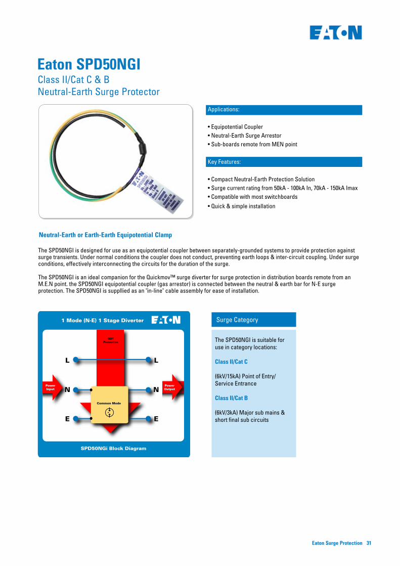
Applications:
• Equipotential Coupler• Neutral-Earth Surge Arrestor• Sub-boards remote from MEN point
Key Features:
• Compact Neutral-Earth Protection Solution• Surge current rating from 50kA - 100kA In, 70kA - 150kA Imax• Compatible with most switchboards
• Quick & simple installation
The SPD50NGI is designed for use as an equipotential coupler between separately-grounded systems to provide protection against surge transients. Under normal conditions the coupler does not conduct, preventing earth loops & inter-circuit coupling. Under surge conditions, effectively interconnecting the circuits for the duration of the surge.
The SPD50NGI is an ideal companion for the Quickmov™ surge diverter for surge protection in distribution boards remote from an M.E.N point. the SPD50NGI equipotential coupler (gas arrestor) is connected between the neutral & earth bar for N-E surge protection. The SPD50NGI is suppllied as an "in-line" cable assembly for ease of installation.
Surge Category
The SPD50NGI is suitable for use in category locations:
Class II/Cat C (6kV/15kA) Point of Entry/ Service Entrance
Class II/Cat B
(6kV/3kA) Major sub mains & short final sub circuits
1 Mode (N-E) 1 Stage Diverter
SPD50NGi Block Diagram
GDTProtection
PowerInput
PowerOutput
Common Mode
Class II/Cat C & B Neutral-Earth Surge Protector
Eaton SPD50NGI
Neutral-Earth or Earth-Earth Equipotential Clamp

Eaton Surge Protection32
Important: Before installing the device, please read & follow the installation & operating instructions.
Technical Specifications SPD50NGI
Protection Mode Single Mode - connected Neutral-Earth or between separately earthed systems
Service type (N-E protection only) TNS or similar (neutral must be grounded either locally or remotely)
System voltage - Un Applicable to any common LV system voltage
Test Classification Class I & II (IEC 61643-1) Cat B & C ANSI C62.41
External disconnector requirements None
DC breakdown voltage (1mA) 230V +/-20%
Firing voltage 800V +-20%
Operating current <1mA
Surge current rating In (20 times) 50kA (8/20us)
Surge current rating Ismax (2 times) 70kA (8/20us)
Residual voltage with full cable <1.3kV (3kA, 8/20uS)
Residual voltage with minimal cable (100mm total)
<1.3kV (15kA, 8/20uS) <2.5kV (50kA, 8/20uS)
Connections 6mm2 cable (black & green/yellow) for connection
Mounting None required for fixed installation (suspended by cable)
Dimensions & Weight 60 x 15 x 15 mm (not including cables), 70g
Sub-board with remote MEN link connection
Eaton SPD50NGISpecifications
Connection Diagram
Due to continual product improvement specifications are subject to change without notice. Copyright 2010 Eaton Corporation.

Eaton Surge Protection 33
Class III/Category A (6kV/200A)Point of Use Protection

Eaton Surge Protection34
Series Power Filter & Shunt Surge Diverter
10A, 220-250V, 60kA
Key Features:
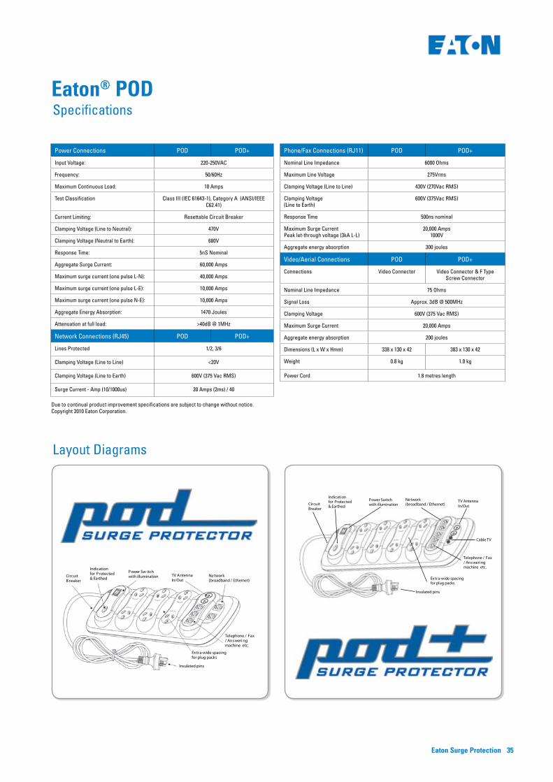
• POD 6 Outlet or POD+ 8 Outlet models• 60,000 Amp surge protection• Highest quality power sockets with extra wide spacing• Visual indication of Power & Surge Protection status• 1.8 metre power cord with insulated pins• Resettable circuit breaker• Power On/Off switch• Data, Video/Aerial & Phone Line surge protection on POD• Data, Video/Aerial, Cable TV & Phone Line surge protection on POD+ • Network cable, telephone cable & Coax cable supplied• Wall mountable to save valuable floor space
The Eaton POD protects your precious Computer System, Home Entertainment System & other valuable electronic equipment from surges, spikes & noise caused by lightning & other power disturbances.
Its series power filter provides superior protection against surges & spikes, with the additional benefit of protecting against line noise that may affect sensitive equipment. With a surge rating of 60kA, the POD out-performs & outlasts many other products that provide shunt-only protection.
The POD not only protects your power circuits, but also protects against “back door” surges that can enter your systems telephone lines, aerials or network cables.
The POD is manufactured from the highest quality materials & is ergonomically & aesthetically designed to suit office & home installations. Rest easy with a five year full replacement warranty & a $100,000 load protection guarantee* (Australia & New Zealand).
2 Mode 3 Element Series Filter3 Mode 2 Stage Surge Diverter
POD Block Diagram
Primary MOV
Protection
Secondary MOV
Protection
Series Blocking Inductors
High FrequencyCapacitor
PowerInput
PowerOutput
Normal Mode
Common Mode
Normal Mode
Common Mode
Surge Category
POD & POD+ are suitable for use in category locations:
Class III/Cat A (6kV/200A) Long final sub circuits & power outlets
Class III/Cat A Surge Powerboard for IT & AV applications
Eaton® POD
Eaton Surge Protection 35
Power Connections POD POD+
Input Voltage: 220-250VAC
Frequency: 50/60Hz
Maximum Continuous Load: 10 Amps
Test Classification Class III (IEC 61643-1), Category A (ANSI/IEEE C62.41)
Current Limiting: Resettable Circuit Breaker
Clamping Voltage (Line to Neutral): 470V
Clamping Voltage (Neutral to Earth): 680V
Response Time: 5nS Nominal
Aggregate Surge Current: 60,000 Amps
Maximum surge current (one pulse L-N): 40,000 Amps
Maximum surge current (one pulse L-E): 10,000 Amps
Maximum surge current (one pulse N-E): 10,000 Amps
Aggregate Energy Absorption: 1470 Joules
Attenuation at full load: >40dB @ 1MHz
Network Connections (RJ45) POD POD+
Lines Protected 1/2, 3/6
Clamping Voltage (Line to Line) <20V
Clamping Voltage (Line to Earth) 600V (375 Vac RMS)
Surge Current - Amp (10/1000us) 20 Amps (2ms) / 40
Circuit B reaker
Indication for Protected & Earthed
Power Sw itch with illumination TV Antenna
In/Out
Ex tra-wide spacing for plug packs
Insulated pins
Telephone / Fax / Answeri ng machine etc.
Network (broadband / Ethernet)
Phone/Fax Connections (RJ11) POD POD+
Nominal Line Impedance 6000 Ohms
Maximum Line Voltage 275Vrms
Clamping Voltage (Line to Line) 430V (270Vac RMS)
Clamping Voltage (Line to Earth)
600V (375Vac RMS)
Response Time 500ns nominal
Maximum Surge CurrentPeak let-through voltage (3kA L-L)
20,000 Amps1000V
Aggregate energy absorption 300 joules
Video/Aerial Connections POD POD+
Connections Video Connector Video Connector & F Type Screw Connector
Nominal Line Impedance 75 Ohms
Signal Loss Approx. 3dB @ 500MHz
Clamping Voltage 600V (375 Vac RMS)
Maximum Surge Current 20,000 Amps
Aggregate energy absorption 200 joules
Dimensions (L x W x Hmm) 338 x 130 x 42 383 x 130 x 42
Weight 0.8 kg 1.0 kg
Power Cord 1.8 metres length
Eaton® PODSpecifications
Layout Diagrams
Circuit B reaker
Indication for Protected & Earthed
Power Sw itch with illumination TV Antenna
In/Out
Ex tra-wide spacing for plug packs
Insulated pins
Telephone / Fax / Answeri ng machine etc.
Network (broadband / Ethernet)
Due to continual product improvement specifications are subject to change without notice. Copyright 2010 Eaton Corporation.

Eaton Surge Protection36
Applications
• Plug-in UPS systems• Servers• Portable instrumentation• POS systems • Small office systems• Industrial & rural surge prone sites
The SSFI is designed to provide secondary protection against power surges caused by external sources such as lightning strikes & substation switching, as well as providing a measure of protection from surge events generated on the secondary side of the filter. The unit has been designed in accordance with AS3100, AS1768, IEC61643-1, IEC61000-6-1, 2, 3, 4 & other standards & codes as applicable.
The SSFI is a 3-stage protection unit utilising primary & secondary MOV protection in conjunction with a Low-Q LC filter. The unit provides filtering of the line harmonics, noise & RF transmitters with a cut-off frequency of <10kHz & a minimum attenuation of 40dB above 1Mhz. The operation status of the SSFI is indicated by lamps on the front panel. The "OK" light indicates that power is applied to the SSFI. The "FAULT" light indicates that the surge protection circuitry is damaged & the unit should be replaced. An ideal device for Category A locations.
Key Features
• Surge suppression & filtering in a single package• Small footprint, modular design• Enclosed in IP 20 painted metal housing• Surge suppression rating of 20kA (L-N)• Protection Fail Indicators• 3 mode, 3 Stage Protection• 12 Month WarrantySurge Filter, 1 Phase 10A & 15A, 25kA Primary
2 Mode 3 Element Series Filter3 Mode 2 Stage Surge Diverter
SSFi Block Diagram
Primary MOV
Protection
Secondary MOV
Protection
Series Blocking Inductors
High FrequencyCapacitor
PowerInput
PowerOutput
Normal Mode
Common Mode
Normal Mode
Common Mode
Surge Category
SSF10I & SSF15I are suitable for use in category locations:
Class III/Cat A
(6kV/200A) Long final sub circuits & power outlets
Class III/Cat A Portable Surge Filter
Eaton® SSFI

Eaton Surge Protection 37
Technical SSF10I SSF15I
Number of ports 2 Port
Method of mounting Portable
Input voltage - Uc 200-250VAC 1 Phase
Maximum Continuous voltage - MCOV 285VAC L-N
Temporary overvoltage - TOV 300VAC L-N, 15 mins
Service type TT, TN, TN C-S or any 1 phase system with a grounded neutral. This unit must not be connected to an ungrounded system.
Test Classification Class II
Energy Absorption rating - per mode (joules) Primary Protection L-N = 370JPrimary Common Mode protection L-E & N-E = 480J
Secondary protection L-N = 225JSecondary Common Mode protection L-E & N-E = 480J
Aggregate rating = 1,555J
Current rating - continuous 10A 15A
Test Classification Class III (IEC 61643-1), Category A (ANSI/IEEE C62.41)
Recommended max. overcurrent protection 10A 15A
Residual current <0.5 mA
Protection modes Line-Neutral, Line-Earth, Neutral-Earth
In 8/20us (Line-Neutral) Nominal surge life 10kA x 20 hits
In 8/20us (Line-Earth) Nominal surge life 3kA x 20 hits
In 8/20us (Neutral-Earth) Nominal surge life 3kA x 20 hits
Ismax 8/20us (Line-Neutral) Max surge level 20kA
Ismax 8/20us (Line-Earth) Max surge level 10kA
Ismax 8/20us (Neutral-Earth) Max surge level 10kA
Filter attenuation 40dB nominal above 1MHz
Initial clamp voltage (Line-Neutral) 560V
Initial clamp voltage (Line-Earth) 680V
Initial clamp voltage (Neutral-Earth) 680V
Residual voltage (Vpl) (Line-Neutral) (Let through voltage) <1100 (3kA, 8/20uS)
Residual voltage (Vpl) (Line-Earth) (Let through voltage) <1400 (3kA, 8/20uS)
Residual voltage (Vpl) (Neutral-Earth) (Let through voltage) <1400 (3kA, 8/20uS)
Internal protection (fusing) Thermal fusing on primary line-connected MOVs
Terminations IEC 320-C14 10A input x 1, , IEC 320-C13 10A output x 1 IEC 320-C20 16A input x 1,, IEC 320-C19 16A output x 1
Alarms/indicators 2 LED display, Power OK, Protection Fault
Location Category Indoor
Enclosure rating IP20
Design Standards: IEC61643-1, IEC610006-1, 2, 3, 4 ANSI/IEEE C62.41 Cat B, C, D, E AS1768-2007 Cat B, C, D, E AS3000, AS3100, CE mark
Dimensions & Weight 155 x 150 x 50 mm (W x D x H), 500g
Environment -10 to 60oC, 0 to 95% RH (non-condensing)
1 2 43
A
B
C
D
4321
D
C
B
A Title
noisiveRrebmuNSize
A4
fo teehS 6002-guA-7:etaDFile: C:\tvss engineering\Product_engineering\current\MSF\MSF.ddbDrawn By:
CF
LINE IN
NEUTRAL IN
EARTH IN
LINE OUT
Differential protectionDifferential and common-mode filtering
CSFi/SSFi/SF1510i/SF8R/POD FILTER LINE DIAGRAM
01 1
JDP
L-N protection
N-E protection L-E protection
L-N protection
NEUTRAL OUT
Common-mode protection.
550247
N-E protectionL-E protection
Thermal fuse
CM TX
Indicator/Alarm
EARTH OUT
Eaton® SSFISpecifications
Line Diagram
Due to continual product improvement specifications are subject to change without notice. Copyright 2010 Eaton Corporation.

Eaton Surge Protection38
DM Series
The new SPD ‘D’ series digital signalling surge diverters are designed for low voltage data signalling systems in the 5 volt to 48 volt range. Models are available in 5, 12, 24 & 48 volt DC. All are IEC 61643-21:2000 compliant.
Class III/Cat A 5-48V Surge Diverters
Eaton SPD-DM Series
Key Features:
• 1 mode plug-in protection• 10kA surge suppression rating• Compact solution for data systems protection• DIN43880 case, 13mm wide
Applications:
• Data networks signalling protection
Specifications:
Part Code Description
SPD-DM05 1 Pole, 5vdc, 10kA, 1 mode Surge Diverter w/ removable module
SPD-DM12 1 Pole, 12vdc, 10kA, 1 mode Surge Diverter w/ removable module
SPD-DM24 1 Pole, 24vdc, 10kA, 1 mode Surge Diverter w/ removable module
SPD-DM48 1 Pole, 48vdc, 10kA, 1 mode Surge Diverter w/ removable module
Technical Specifications SPD-DM05 SPD-DM12 SPD-DM24 SPD-DM48
Nominal Voltage Un 5 12 24 48
Max Continuous Voltage Uc AC/DC 5/6 12/15 24/28 48/60
Nominal Discharge Current ( 8/20us, kA ) per line. Inom. 5 5 5 5
Max Discharge Current ( 8/20us, kA ) Per line. Imax. 10 10 10 10
Nominal current (A) IL 0.5 0.5 0.5 0.5
Voltage Protection Level ( 8/20us, V ) UpLine –LineLine - Ground
<80v<350v
<150v<350v
<200v<500v
<250v<500v
Voltage Protection Level ( 1KV/us, V ) UpLine - LineLine - ground
<10v<600v
<18v<600v
<30v<600v
<70v<600v
Series impedance per line ( Ohm ) 4 4 4 4
Insertion loss at 100Mhz (dB) <3.0 <3.0 <3.0 <3.0
Degree of protection ( IP rating ). 20 20 20 20
Mounting Din rail Din rail Din rail Din rail
Enclosure material UL94 V0 UL94 V0 UL94 V0 UL94 V0
Environment temperature ( C ) -40 to 80c, 0-90% RH
-40 to 80c, 0-90% RH
-40 to 80c, 0-90% RH
-40 to 80c, 0-90% RH
Warranty ( months ) 12 12 12 12
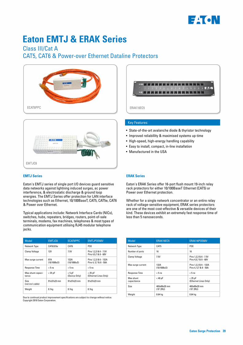
Eaton Surge Protection 39
ECAT6PPC
EMTJC6
ERAK16EC5
EMTJ Series
Eaton's EMTJ series of single port I/O devices guard sensitive data networks against lightning induced surges, ac power interference, & electrostatic discharge & ground loop energies. The EMTJ Series offer protection for LAN interface technologies such as Ethernet, 10/100BaseT, CAT5, CAT5e, CAT6 & Power over Ethernet.
Typical applications include: Network Interface Cards (NICs), switches, hubs, repeaters, bridges, routers, point-of-sale terminals, modems, fax machines, telephones & most types of communication equipment utilising RJ45 modular telephone jacks.
ERAK Series
Eaton's ERAK Series offer 16-port flush mount 19-inch relay rack protectors for either 10/100BaseT Ethernet (CAT5) or Power over Ethernet protection.
Whether for a single network concentrator or an entire relay rack of voltage-sensitive equipment, ERAK series protectors are one of the most cost-effective & versatile devices of their kind. These devices exhibit an extremely fast response time of less than 5 nanoseconds.
Model EMTJC6 ECAT6PPC EMTJPOE60V
Network Type CAT6/5/5e CAT6 POE
Clamp Voltage 12V 7.5V Pins 1,2,3 & 6 - 7.5V Pins 4,5,7 & 8 - 60V
Max surge current 97A(10/1000uS)
132A(10/1000uS)
Pins 1,2,3 & 6 - 132APins 4, 5,7 & 8 - 50A
Response Time < 5 ns < 5 ns < 5 ns
Max shunt capaci-tance
< 25 pF < 5 pF (Device Only)
< 25 pF(Ethernet Lines Only)
Size (not incl cable)
91x37x23 mm 91x37x23 mm 91x37x23 mm
Weight 0.1kg 0.1kg 0.1kg
Model ERAK16EC5 ERAK16POE60V
Network Type CAT5 POE
Number of ports 16 16
Clamp Voltage 7.5V Pins 1,2,3 & 6 - 7.5V Pins 4,5,7 & 8 - 60V
Max surge current 132A(10/1000uS)
Pins 1,2,3 & 6 - 132APins 4, 5,7 & 8 - 50A
Response Time < 5 ns < 5 ns
Max shunt capacitance
< 40 pF < 25 pF(Ethernet Lines Only)
Size 483x89x20 mm(19" 2RU)
483x89x20 mm(19" 2RU)
Weight 0.64 kg 0.64 kg
Eaton EMTJ & ERAK Series
Due to continual product improvement specifications are subject to change without notice. Copyright 2010 Eaton Corporation.
ECAT6PPC
EMTJC6
ERAK16EC5
Class III/Cat A CAT5, CAT6 & Power-over Ethernet Dataline Protectors
Key Features:
• State-of-the-art avalanche diode & thyristor technology • Improved reliabillity & maximised systems up-time• High-speed, high-energy handling capability• Easy to install, compact, in-line installation• Manufactured in the USA

Eaton Surge Protection40
The SF8RM is designed to protect equipment against power surges & electrical noise whilst providing a convenient combination of power outlets to suit most applications. A unique mounting system allows mounting in many different modes to suit crowded racks. Even if no rack space exists, the units may be mounted externally on the front or rear of the rack. For horizontal mounting, the units require a single 1RU rack space for installation. The unit may also be flush mounted to either side of a rack or cabinet.
Technical Specifications SF8RM
Current rating 10A total
Configuration Single-phase, L/N/E.
Surge Protection Category AS/NZS1768-2007 Category B
Primary protection modes L-N, L-E, & N-E
Secondary protection modes L-N, L-E, & N-E
Surge rating (8/20uS L-N) 22.5kA
Let-through voltage < 700V@ 3kA
Overvoltage withstand 300VRMS
Filter type Low Q/low C filter providing differential & common-mode filtering.
Attenuation > 50dB above 1MHz.
Voltage drop Less than 3V at rated load.
Input connection Approved power cord with Australian 10A plug
Output connections Australian 3 pin 10A (x8).
Enclosure Steel, powder coated, black.
Dimensions (without brackets) 441 x 120 x 44 mm (W x D x H)
Weight 1.2kg
Eaton® SF8RMClass II & III/Cat B & A Single Phase Rack Mounted Filter/PDU
Surge Filter, 1 Phase 10A, 25kA Primary
Due to continual product improvement specifications are subject to change without notice. Copyright 2010 Eaton Corporation.
Key Features
• 8 way 10A Power Filter• Can be rack or surface mounted• 3 mode, 3 stage protection• Resettable circuit breaker for over-current protection

Eaton Surge Protection 41
Qui
ck P
rodu
ct S
elec
tion
Gui
deFo
r use
in c
omm
erci
al, i
ndus
trial
& d
omes
tic a
pplic
atio
ns
Su
rge
P
rote
ctio
n
P
rod
uct
Cla
ss /
Cat
ego
ry
AN
SI/I
EE
E
C6
2.4
1
Co
nn
ecti
on
/P
has
esN
om
inal
S
urg
e
Cu
rren
t (In
)
L-N
x 2
0 h
its
Max
Su
rge
Cu
rren
t (m
ax)
L-N
Max
Lo
ad
Cu
rren
tP
rote
ctiv
e M
od
esS
hu
nt
Div
ers
ion
S
tag
es
Mo
un
tin
gC
E M
ark
A
pp
lica
ble
Y
/N
Po
wer
Fi
lter
ing
Y
/N
Sta
tus
Ind
icat
ors
Y
/N
Rem
ote
A
larm
Y
/N
Dim
ensi
on
s &
Wei
gh
t
Po
rtab
le S
urg
e P
ow
er F
ilte
rs
PO
DIII
/ A
Cor
d3k
A40
kA10
AL-
N, L
-E, N
-E2
Por
tabl
eN
oYe
sYe
sN
o33
8x13
0x42
mm
, 800
g
PO
D+
III /
AC
ord
3kA
40kA
10A
L-N
, L-E
, N-E
2P
orta
ble
No
Yes
Yes
No
383x
130x
42m
m, 1
kg
SS
F10I
/ 15
IIII
/ A
Cor
d10
kA25
kA10
A /
15A
L-N
, L-E
, N-E
2P
orta
ble
Yes
Yes
Yes
No
150x
140x
50m
m, 5
00g
Har
dw
ired
Su
rge
Div
erte
rs
SP
DQ
M1
II / B
, C1
30kA
60kA
N/A
L-N
1-
No
No
Yes
No
25x7
1x93
mm
, 0.3
kg
SP
D50
NG
III
/ B-
50kA
(N-E
)70
kA (N
-E)
N/A
N-E
1C
able
No
No
No
No
60x1
5x15
mm
, 0.1
5kg
SP
DV
60-3
00II
/ B, C
130
kA60
kAN
/AL-
N1
DIN
Yes
No
Yes
Yes
18x6
5x97
mm
, 0.1
kg
SP
DT6
0-25
5II
/ B-
40kA
60kA
N/A
N-E
1D
INYe
sN
oYe
sYe
s18
x65x
97m
m, 0
.1kg
SP
D12
0III
/ B, C
150
kA10
0kA
N/A
L-N
or
L-E
1D
IN R
ail
Yes
No
Yes
Yes
70x6
8x90
mm
, 200
g
SP
D3N
/ G
III
/ B, C
320
kA40
kA/p
hN
/AL-
N, N
-E o
r L-
N, L
-E1
DIN
Rai
lYe
sN
oYe
sYe
s70
x68x
90m
m, 2
00g
MS
DI
II / B
, C3
75kA
/ph
200k
A/p
hN
/AL-
N, L
-E, N
-E1
Sur
face
Yes
No
Yes
Yes
370x
160x
560m
m, 1
4kg
Har
dw
ired
Su
rge
Po
wer
Fil
ters
CS
FIII
/ B1
10kA
25kA
25A
L-N
, L-E
, N-E
2D
IN R
ail
Yes
Yes
Yes
Yes
70x6
8x90
mm
, 200
g
DS
FIII
/ B1
15kA
50kA
32A
L-N
, L-E
, N-E
2S
urfa
ceYe
sYe
sYe
sYe
s14
0x50
x270
mm
, 1.5
kg
MS
FXX
1III
/ B &
C1
60kA
160k
A40
A o
r 63
AL-
N, L
-E, N
-E2
Sur
face
Yes
Yes
Yes
Yes
210x
160x
560m
m, 9
kg
MS
FXX
3III
/ B &
C3
60kA
/ph
160k
A/p
h40
A o
r 63
AL-
N, L
-E, N
-E2
Sur
face
Yes
Yes
Yes
Yes
370x
160x
560m
m, 1
4kg
PP
FII &
II /
A,B
,C,D
3C
Ei =
30k
A/p
h D
Ei =
45k
A/p
h E
Ei =
90k
A/p
h
CE
i = 8
0kA
/ph
DE
i = 1
20kA
/ph
EE
i = 2
40kA
/ph
100A
, 160
A,
200A
, 315
A,
400A
L-N
, N-E
2S
urfa
ceYe
sYe
sYe
sYe
s10
0-25
0A =
600
x 2
00 x
80
0mm
, 50-
60kg
31
5A &
400
A =
800
x 4
00 x
10
00m
m, 1
00kg
Dat
alin
e N
etw
ork
Tra
nsi
ent
Pro
tect
ors
ER
AK
16E
C5
III /
A-
N/A
132A
/por
tN
/AW
-W, W
-E1/
port
19" R
ack
No
N/A
No
No
483x
98x2
0mm
, 0.6
4kg
EM
TJC
6III
/ A
-N
/A97
AN
/AW
-W, W
-E1
Por
tabl
eN
oN
/AN
oN
o91
x37x
23m
m, 0
.1kg
EC
AT6
PP
CIII
/ A
-N
/A13
2AN
/AW
-W, W
-E1
Por
tabl
eN
oN
/AN
oN
o91
x37x
23m
m, 0
.1kg
Rac
km
ou
nt
Po
wer
Fil
ters
SF8
RM
III /
AC
ord
N/A
22.5
kA10
AL-
N, L
-E, N
-E2
19" R
ack
No
Yes
Yes
No
441x
120x
44m
m, 1
.2kg

Eaton Surge Protection42
For UPS ratings above 160 kVA please contact your Eaton representative for further information.
UPS & Surge Filter Selection Guide
UPS Model Rating Main (Rectifier) Input Surge Filter Bypass Input Surge Filter
Powerware 5125
PW51251000A 1kVA SSF10I NA
PW51251500A 1.5kVA SSF10I NA
PW51252000A 2kVA SSF10I NA
PW51252200A 2.2kVA SSF10I NA
Powerware 5130
PW5130i1250-XL2U 1.25kVA SSF10I NA
PW5130i1750-XL2U 1.75kVA SSF10I NA
PW5130i2500-XL2U 2.5kVA SSF15I NA
PW5130i3000-XL2U 3kVA SSF15I NA
Powerware 9120 Dual or Single Input UPS, for single input use Rectifier input rating
PW91206000A 6kVA DSFI DSFI
Powerware 9130
PW9130G700T-XLAU 0.7kVA SSF10I plug/play, or CSFI/DSFI Hardwired NA
PW9130G1000T-XLAU 1kVA SSF10I plug/play, or CSFI/DSFI Hardwired NA
PW9130G1500T-XLAU 1.5kVA SSF10I plug/play, or CSFI/DSFI Hardwired NA
PW9130G2000T-XLAU 2kVA SSF10I plug/play, or CSFI/DSFI Hardwired NA
PW9130G3000T-XLAU 3kVA SSF15I plug/play, or CSFI/DSFI Hardwired NA
PW9130G1000R-XL2UAU 1kVA SSF10I plug/play, or CSFI/DSFI Hardwired NA
PW9130G2000R-XL2UAU 2kVA SSF10I plug/play, or CSFI/DSFI Hardwired NA
PW9130G3000R-XL2UAU 3kVA SSF15I plug/play, or CSFI/DSFI Hardwired NA
Powerware 9135
PW9135G6000-XL3U 6kVA DSFI NA
Powerware 9140 Dual or Single Input UPS, for single input use Rectifier input rating
PW91407500HW 7.5kVA DSFI DSFI
PW914010000HW 10kVA DSFI DSFI
Powerware 9155S Dual or Single Input UPS, for single input use Rectifier input rating
PW91558iSxx 8kVA MSF401CCMI MSF401CCMI
PW915510iSxx 10kVA MSF631CCMI MSF631CCMI
Powerware 9155N Dual Input UPS, 3 Phase Rectifier, 1 Phase Bypass
PW91558iNxx 8kVA MSF403CCMI MSF401CCMI
PW915510iNxx 10kVA MSF403CCMI MSF631CCMI
PW915512iNxx 12kVA MSF403CCMI MSF631CCMI
PW915515iNxx 15kVA MSF403CCMI MSF631CCMI
PW915520iNxx 20kVA MSF403CCMI Contact Eaton
PW915530iNxx 30kVA MSF403CCMI Contact Eaton
Powerware 9355 Dual or Single Input UPS, for single input use Rectifier input rating
93558Nxx 8kVA MSF403CCMI MSF403CCMI
935510Nxx 10kVA MSF403CCMI MSF403CCMI
935512Nxx 12kVA MSF403CCMI MSF403CCMI
935515Nxx 15kVA MSF403CCMI MSF403CCMI
935520Nxx 20kVA MSF633CCMI MSF403CCMI
935530Nxx 30kVA MSF633CCMI MSF633CCMI
935540Nxx 40kVA PPF1003CEi MSF633CCMI
Powerware 9390 Dual or Single Input UPS, for single input use Rectifier input rating
PW939040N 40kVA PPF1003CEi MSF633CCMI
PW939060U 60kVA PPF1003CEi PPF1003CEi
PW939080N 80kVA PPF1603CEi PPF1603CEi
PW9390100U 100kVA PPF2003CEi PPF1603CEi
PW9390120N 120kVA PPF3003CEi PPF2003CEi
PW9390120U 120kVA PPF3003CEi PPF2003CEi
PW9390160N 160kVA PPF4003CEi PPF3003CEi

Eaton Surge Protection 43
Eaton’s Quickmov™ is a fully integrated Surge Protection Device (SPD), designed for stand-alone mounting or to plug straight into a Quicklag™ loadcentre, connecting to the chassis busbar for the lowest source impedance. Quickmov™ employs advanced MOV technology with embedded thermal protection housed in a dual barrier flame retardant case to provide optimum surge protection performance. With a 60kA surge suppression rating, Quickmov™ is
ideal for primary protection in main switchboards and can be used in conjunction with an Eaton Neutral-Earth arrestor for distribution boards remote from the M.E.N point. Quickmov™ combines surge diversion with fail-safe protection to deliver unsurpassed levels of safety and performance.
Quickmov™
Fast, Safe &Dependable
Safety and Performance.

Eaton Corporation is a diversified power management company rankedamong the largest Fortune 500 companies. The electrical group is Eaton’slargest division & is a global leader in electrical control, power distribution, power quality, automation, & monitoring products andservices. Eaton’s global electrical brands, including Cutler-Hammer®,MGE Office Protection Systems™, Powerware®, Holec®, MEM®, Santakand Moeller, provide customer-driven PowerChain Management®
solutions to serve the power system needs of the industrial, institutional,government, utility, commercial, residential, IT, mission critical & OEMmarkets worldwide.
PowerChain Management solutions help enterprises achieve sustainableand competitive advantages through proactive management of thepower system as a strategic, integrated asset throughout its life cycle.With Eaton’s distribution, generation & power quality equipment,full-scale engineering services & information management systems,the power system is positioned to deliver powerful results: greaterreliability, operating cost efficiencies, effective use of capital, enhancedsafety & risk mitigation.
PowerChain Management is a trademark of Eaton Corporation. All other trademarks are property of their respective owners.
©2010 Eaton CorporationAll Rights ReservedPrinted in AUS077PQ
Eaton Industries Pty. Ltd.Electrical Sector10 Kent Road Mascot,NSW 2020 Australia1300 3 EATON (1300 3 332 866)www.eaton.com/powerquality www.eatonelectric.com.au