Embed Size (px)
Citation preview
Preprint typeset in JINST style - HYPER VERSION
Testing of High Voltage Surge Protection Devices forUse in Liquid Argon TPC Detectors
J. Asaadia, J.M. Conradb, S. Gollapinnic, B.J.P. Jonesb∗, H. Jostleind , J.M. St. Johne,T. Strauss f , S. Wolbersd , and J. Zennamog.
aSyracuse University, 900 South Crouse Ave, Syracuse, NY 13244, USAbMassachusetts Institute of Technology, 77 Massachusetts Avenue, Cambridge, MA 02139, USAE-mail: [email protected]
cKansas State University, Manhattan, KS 66506, USAdFermi National Accelerator Laboratory, Batavia, IL 60510, USAeUniversity of Cincinnati, 2600 Clifton Ave, Cincinnati, OH 45220, USAf University of Bern, Albert Einstein Center, LHEP, Sidlerstasse 5, CH-3012 Bern, SwitzerlandgUniversity of Chicago, Enrico Fermi Institute, 5801 S Ellis Ave, Chicago, IL 60637, USA
ABSTRACT: In this paper we demonstrate the capability of high voltage varistors and gas dischargetube arrestors for use as surge protection devices in liquid argon time projection chamber detectors.The insulating and clamping behavior of each type of device is characterized in air (room temper-ature), and liquid argon (90 K), and their robustness under high voltage and high energy surges incryogenic conditions is verified. The protection of vulnerable components in liquid argon during a150 kV high voltage discharge is also demonstrated. Each device is tested for argon contaminationand light emission effects, and both are constrained to levels where no significant impact upon liq-uid argon time projection chamber functionality is expected. Both devices investigated are shownto be suitable for HV surge protection applications in cryogenic detectors.
KEYWORDS: Cryogenic detectors; Noble liquid detectors (scintillation, ionization,double-phase); Voltage distributions.
∗Corresponding Author
arX
iv:1
406.
5216
v2 [
phys
ics.
ins-
det]
23
Jun
2014

Contents
1. Introduction 1
2. Devices under test 4
3. Behaviour under cryogenic conditions 6
4. Robustness under repeated surges in liquid argon 10
5. Practical considerations for use in LArTPCs 145.1 Purity considerations 145.2 Light emission 17
6. Conclusions 18
1. Introduction
Large liquid argon time projection chambers (LArTPCs) are of great importance to the field ofexperimental neutrino physics [1–5]. The increasing scale of such detectors is motivated by theneed to collect a large sample of neutrino interactions, often at a distance from a pulsed neutrinobeam. Liquid argon TPCs for direct dark matter detection [6–10] are also increasing in scale, a largefiducial volume being required to explore the parameter space of small dark matter interaction crosssections which the next generation of such experiments intends to probe.
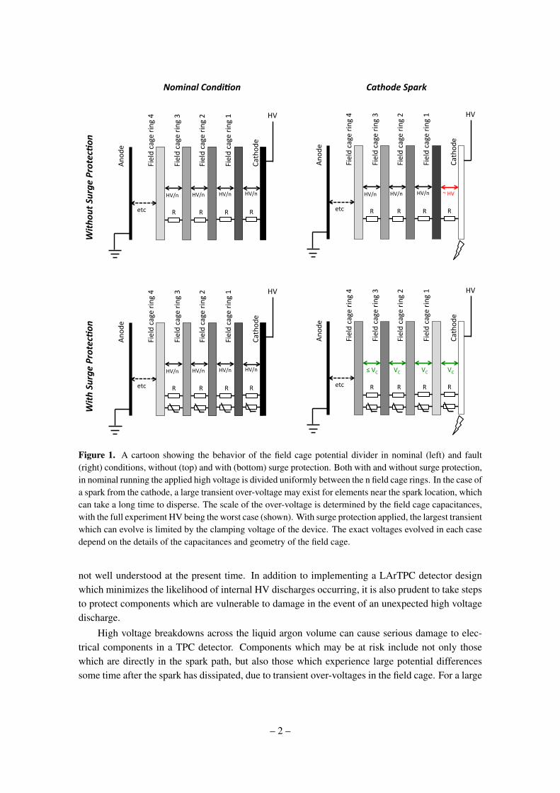
To provide a strong enough electric field for electron drift over a large distance to readoutwires near ground, a high voltage must be supplied to the cathode of the TPC. To increase the driftlength of a liquid argon TPC whilst maintaining a fixed electric field strength, the high voltagesupplied must increase proportionally. For the present generation of large LArTPCs, voltages oforder 100 kV are required in order to provide a constant 500 V/cm electric field for approximatelytwo meters. To ensure uniformity, this field is usually shaped by a series of field cage rings whichare connected by resistors, thus creating a voltage divider. This network is shown schematically inFigure 1, top left.
The need for larger LArTPC detectors with higher applied voltages has led to new studiesof the dielectric strength of liquid argon [11–13]. In contrast to the commonly used referencevalue of 1.4 MV/cm from Ref. [14], which was measured using only moderately pure argon, recentinvestigations have shown that the dielectric strength of argon at LArTPC purity with sub-ppbconcentrations of oxygen and water may be much lower than anticipated, with Ref. [12] reportingbreakdowns at 40 kV/cm. In addition to argon purity, the breakdown voltage of liquid argon alsodepends upon electrode geometry, surface finish and accumulated space charge in ways which are
– 1 –
Cathod
e
Field cage ring 1
Field cage ring 2
Field cage ring 3
Field cage ring 4
HV/n
etc
HV An
ode
HV/n HV/n HV/n
R R R R
Cathod
e
Field cage ring 1
Field cage ring 2
Field cage ring 3
Field cage ring 4
HV/n
etc
HV
Anod
e
HV/n HV/n HV/n
R R R R
Cathod
e
Field cage ring 1
Field cage ring 2
Field cage ring 3
Field cage ring 4
HV/n
etc
HV
Anod
e
HV/n HV/n ~ HV
R R R R
Cathod
e
Field cage ring 1
Field cage ring 2
Field cage ring 3
Field cage ring 4
etc
HV
Anod
e
VC
R R R R
VC VC ≤ VC
With
Surge
Protec.on
With
out S
urge
Protec.on
Nominal Condi.on Cathode Spark
Figure 1. A cartoon showing the behavior of the field cage potential divider in nominal (left) and fault(right) conditions, without (top) and with (bottom) surge protection. Both with and without surge protection,in nominal running the applied high voltage is divided uniformly between the n field cage rings. In the case ofa spark from the cathode, a large transient over-voltage may exist for elements near the spark location, whichcan take a long time to disperse. The scale of the over-voltage is determined by the field cage capacitances,with the full experiment HV being the worst case (shown). With surge protection applied, the largest transientwhich can evolve is limited by the clamping voltage of the device. The exact voltages evolved in each casedepend on the details of the capacitances and geometry of the field cage.
not well understood at the present time. In addition to implementing a LArTPC detector designwhich minimizes the likelihood of internal HV discharges occurring, it is also prudent to take stepsto protect components which are vulnerable to damage in the event of an unexpected high voltagedischarge.
High voltage breakdowns across the liquid argon volume can cause serious damage to elec-trical components in a TPC detector. Components which may be at risk include not only thosewhich are directly in the spark path, but also those which experience large potential differencessome time after the spark has dissipated, due to transient over-voltages in the field cage. For a large
– 2 –
liquid argon TPC like MicroBooNE or LBNE, typical capacitances between elements of the fieldcage will be of order 0.1−1 nF, whereas the resistances between some elements in the field cagenetwork are of order 0.1−1 GΩ. This suggests that the relaxation time of the system after a high-voltage discharge may be of order 0.1−1 s. During this time, a significant fraction of the full highvoltage of the experiment can be held between elements which would ordinarily only experience amoderate potential difference. An over-voltage in case of a discharge arises due to the distributionof interelectrode capacitances given by the geometry of the electrode (cathode-field cage-cryostat)system. The field cage voltage divider without and with surge protection is illustrated schematicallyin Figure 1.
One method of protecting electrically sensitive components from large transient over-voltagesis the application of a surge arrestor. A surge arrestor is a device which is insulating at low voltages,but allows a current to flow if a critical voltage is exceeded. This prevents large potential differencesfrom being developed across a vulnerable component by allowing charge to be redistributed withinthe system more quickly than is allowed by the intrinsic resistances. Commercially available surgeprotectors include varistors [15] and gas discharge tubes (GDTs) [16], both of which are usedwidely in various industrial applications. The commercially available surge arrestors at the timeof writing have not been rated for use at liquid argon temperatures and none have been previouslyused in a running LArTPC detector.
In this paper we report on tests of high voltage GDTs and varistors for the protection of vul-nerable components in the event of HV discharges in LArTPCs. The specific application whichinitiated this investigation is the protection of field cage resistors for the MicroBooNE detector.The requirements for this application are given below. The derivation of these requirements basedon the MicroBooNE TPC geometry and electrical properties, as well as the experimental testingperformed to verify these properties, are outside the scope of this paper and will be reported ina future publication [17]. Our goal is to demonstrate that both GDTs and varistors continue tofunction well in a cryogenic environment and do not have detrimental effects on key aspects ofLArTPC operation, and as such are appropriate for both this specific application, and more generaluse cases in cryogenic TPC detectors. The requirements for a surge protection device suitable forthe MicroBooNE detector are:
• The device must have a significantly higher resistance than the field cage resistances of250 MΩ at the nominal operating voltage of 2 kV.
• The device must clamp the over-voltage that evolves during a fault condition to less than thevoltage which can damage the field cage resistors in liquid argon, determined experimentallyto be 30 kV.
• The device must be able to survive repeated discharges of the system, which are estimated todeposit at most 2 J of energy per device
• The device must function in cryogenic temperatures and in the dielectric environment ofLArTPC purity liquid argon.
• The device must not damage the argon purity in the detector
– 3 –
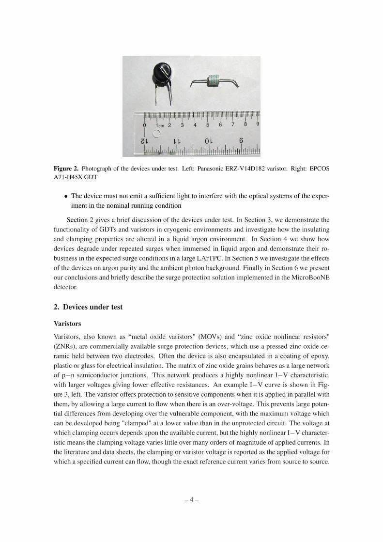
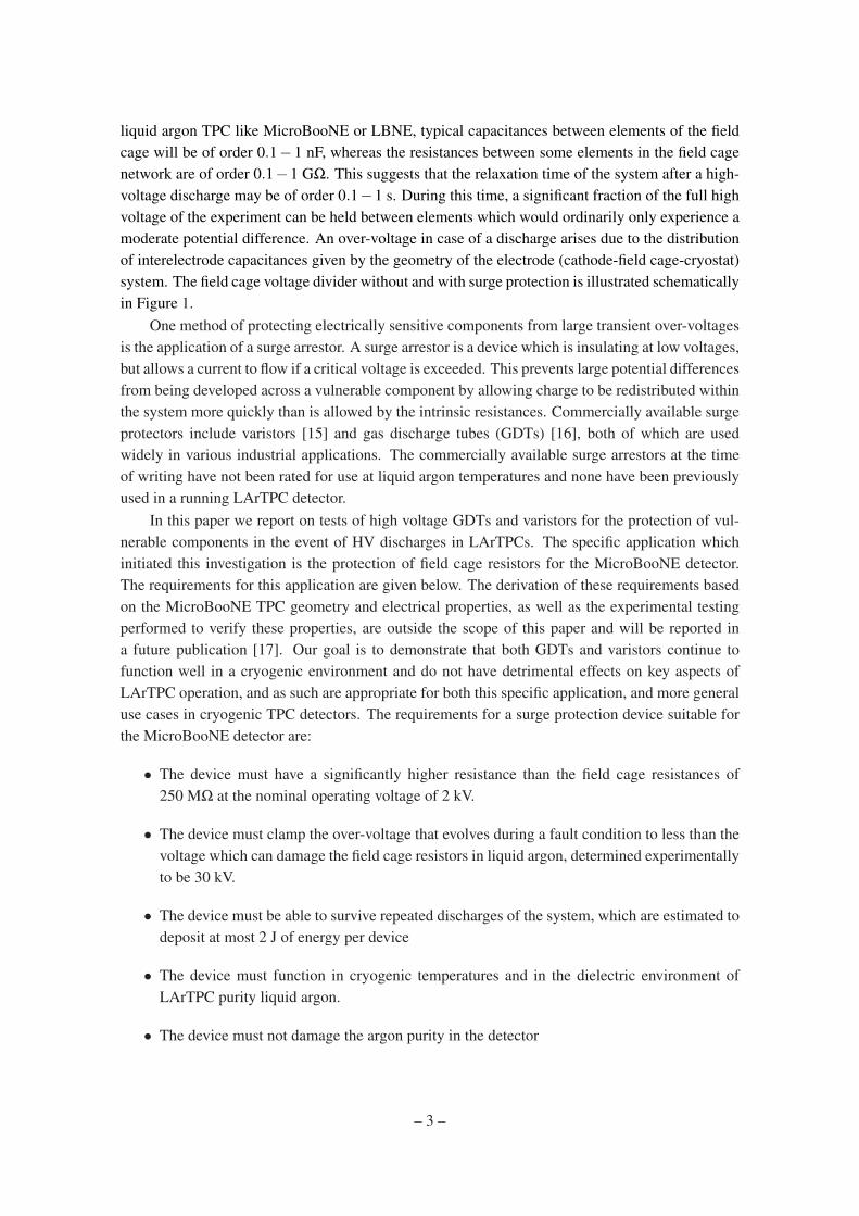
Figure 2. Photograph of the devices under test. Left: Panasonic ERZ-V14D182 varistor. Right: EPCOSA71-H45X GDT
• The device must not emit a sufficient light to interfere with the optical systems of the exper-iment in the nominal running condition
Section 2 gives a brief discussion of the devices under test. In Section 3, we demonstrate thefunctionality of GDTs and varistors in cryogenic environments and investigate how the insulatingand clamping properties are altered in a liquid argon environment. In Section 4 we show howdevices degrade under repeated surges when immersed in liquid argon and demonstrate their ro-bustness in the expected surge conditions in a large LArTPC. In Section 5 we investigate the effectsof the devices on argon purity and the ambient photon background. Finally in Section 6 we presentour conclusions and briefly describe the surge protection solution implemented in the MicroBooNEdetector.
2. Devices under test
Varistors
Varistors, also known as “metal oxide varistors" (MOVs) and “zinc oxide nonlinear resistors"(ZNRs), are commercially available surge protection devices, which use a pressed zinc oxide ce-ramic held between two electrodes. Often the device is also encapsulated in a coating of epoxy,plastic or glass for electrical insulation. The matrix of zinc oxide grains behaves as a large networkof p−n semiconductor junctions. This network produces a highly nonlinear I−V characteristic,with larger voltages giving lower effective resistances. An example I−V curve is shown in Fig-ure 3, left. The varistor offers protection to sensitive components when it is applied in parallel withthem, by allowing a large current to flow when there is an over-voltage. This prevents large poten-tial differences from developing over the vulnerable component, with the maximum voltage whichcan be developed being "clamped" at a lower value than in the unprotected circuit. The voltage atwhich clamping occurs depends upon the available current, but the highly nonlinear I−V character-istic means the clamping voltage varies little over many orders of magnitude of applied currents. Inthe literature and data sheets, the clamping or varistor voltage is reported as the applied voltage forwhich a specified current can flow, though the exact reference current varies from source to source.
– 4 –
Figure 3. Left: I-V characterstic for the Panasonic ERZ range of varistors, from Ref. [15]. Right: measuredI−V characteristic of series combinations of Panasonic ERZ-V14D182 varistors in air, shown on a linearscale to demonstrate additivity of clamping voltages. The clamping voltage scales by a factor of N for Nvaristors in series.
For the purposes of this paper, we will define the clamping voltage as the applied voltage when0.5 mA of current can flow. For more information on the physics and functionality of varistors, seeRef. [18].
Commercially available varistors of the appropriate size for mounting on a MicroBooNE-scaleTPC field cage span clamping voltages from 6 to 1800 V. Since this voltage range is below the re-quired 2 kV, no single device appears to be appropriate for field cage protection, where the nominalapplied voltage 2 kV must be held with low current leakage. This is a commonly encounteredsituation in the field of surge protection, and can solved by applying N devices in series [19]. Theapplied voltage is then shared approximately equally between devices, effectively increasing theclamping voltage by a factor of N. Even if there are small mismatches between the I−V charac-teristics of the individual units, the smoothly varying nature of the I−V curve ensures that a stablevoltage sharing is achieved for any series combination. The measured I−V characteristic for asingle varistor and sets of two and three in series are shown in Figure 3, right.
By adjusting the varistor grain size, device dimensions and dopant composition, differentclamping voltages and energy tolerances can be achieved. The device we investigate in this paperis the Panasonic ERZ-V14D182 [15], whose I−V curve is shown on the left hand side of Figure 3.This device has a clamping voltage of 1800 V, a maximum surge energy rating of 510 J for anindustry standard 8/20 µs pulse, and is rated for the temperature range −40 to +85 C. Two or threedevices in series can provide an appropriate clamping behavior for the MicroBooNE application.
Gas Discharge Tubes (GDTs)
Gas discharge tube arrestors, or GDTs, are commercially available surge protection devices whichconsist of a small volume of gas inside a ceramic housing, in contact with two electrodes. In theevent of an over-voltage, a spark forms between the electrodes which allows a large current to flow.
– 5 –
Current continues to flow until the voltage across the device drops below the extinction voltage. Theamount of charge which flows across the device before extinction occurs depends on the availablecurrent feeding the discharge. At the spark voltage, GDTs undergo a discontinuous transition fromthe resistive to conductive state, causing the device to act as a crowbar. This transition, and theeventual extinction, may not always occur at exactly the same voltage with repeated pulses. Thismeans that unlike varistors, GDTs do not have a smooth and well defined I−V characteristic.
By changing the device geometry, and gas composition and pressure, different spark-overvoltages can be achieved. For the application described above, we require a GDT with a DCbreakdown voltage above 2 kV, but below 30 kV. The device we investigate in this paper is theEPCOS A71-H45X [20], which has a DC spark-over voltage of 4500 V, an insulation resistancespecification of > 10 GΩ, a current rating of 2.5 kA for an industry standard 8/20 µs pulse, and atemperature rating of −40 to +90 C. Extinction occurs at around 500 V warm and cold. Deviceswith both higher and lower DC spark-over voltages are available. For the model chosen, a singleunit can provide the appropriate clamping behaviour for the MicroBooNE applicaiton.
3. Behaviour under cryogenic conditions
It is vital for the proper function of a surge arrestor that it remain sufficiently insulating under thenominal applied voltage, and become sufficiently conducting to provide clamping in a surge condi-tion. We observe that both varistors and GDTs experience changes in their electrical characteristicswhen operated at cryogenic temperatures. The varistor voltage and GDT DC spark-over voltagewere characterized for 168 varistors and 60 GDTs both in air (warm) and in liquid argon (cold).Batches of around 20 devices were mounted on a specially constructed wheel which can be steeredto place electrical contacts across each component sequentially. This test wheel was operated bothin the air and immersed in an open dewar of liquid argon to characterize a large sample of devices.
For each device, the voltage supplied using a calibrated DC high voltage supply is graduallyincreased from zero. For varistors, the voltage supplied when a total current of 0.5 mA is drawnis recorded. For GDTs, we record the largest voltage supplied before the GDT transitions into aconducting mode, exceeding the 0.8 mA trip current of the power supply. In what follows we willrefer to the relevant recorded voltage as the clamping voltage, despite the different definition ineach case. For the first batch of 20 devices the repeatability of the characterization was establishedby measuring the warm clamping voltage two times each. These data are shown in Figure 4. Thevaristors have a clamping voltage which is repeatably measurable to within a few volts. The GDTshave more variability in the clamping voltage, taking a somewhat random value each time. Alldevices clamp well within their specification, which is 1800+180
−100 V for the varistors, and 4500±900 V for GDTs.
The clamping voltage was compared warm and cold for the two samples. The cool-downprocedure involved holding the devices in the argon vapor around 10 cm from the liquid surfacefor around 10 minutes, before immersing the wheel completely in the liquid. A further 10 minuteswas allowed for the temperature of the wheel and attached devices to equilibrate with the liquidargon. The warm and cold clamping points of each device are shown in Figure 5. For varistorsthe clamping voltage always drops when cold, and there is a strong correlation between the warm
– 6 –

Figure 4. Repeatability of warm clamping measurement for varistors (left) and GDTs (right). Measurement1 and measurement 2 were made for the same device, approximately 30 minutes apart. The varistors have avery stable clamping point, whereas the voltage at which GDTs clamp is somewhat random each time.
Figure 5. Cold versus warm clamping voltage for varistors (left) and GDTs (right).
and cold values. For GDTs there is no clear correlation, although the cold clamping voltages aretypically lower and more scattered than warm.
As well as being suitably conducting in the surge regime, a surge protection device must besufficiently insulating under the nominal applied voltage. For our application this is 2 kV for singledevices, or 2 kV/N per device for N devices in series, where for varistors N must be at least 2. Theleakage current for both varistors and GDTs was investigated both warm and cold.
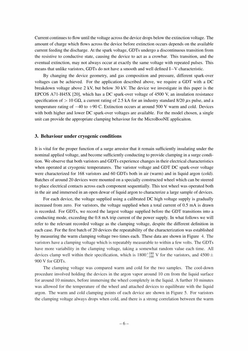
For varistors, a stable DC current is drawn at the nominal applied voltage. To measure thevaristor curve warm and cold, the circuit shown in Figure 6, left was used. The measured I−Vcharacteristic warm and cold is shown in Figure 6, right. The interpretation of the leakage currentover long timescales is not trivial, since the varistor has a finite capacitance which charges througha large resistance. This results in a capacitive component to the leakage current which decays over
– 7 –
Vmeas
1 kΩ 1 MΩ
Vapplied
1.E+06'
1.E+07'
1.E+08'
1.E+09'
1.E+10'
1.E+11'
1.E+12'
1.E+13'
0' 500' 1000' 1500' 2000'
Effec%v
e'Re
sistan
ce'(Ω
)'
Voltage'over'Varistor'(V)'
Warm'
Cold'
Figure 6. Left: circuit used to characterize varistor leakage behavior in warm and cold. Right: effectivevaristor resistance measured in warm and cold conditions.
Vmeas
1 MΩ 1 GΩ
Vapplied
Figure 7. Top: circuit used to characterize GDT leakage behavior in warm and cold. Bottom: effectiveleakage current and resistance measured in warm and cold conditions at 2 kV applied voltage.
a few minute timescale as well as a possible DC resistive component. The measurements shown infigure 6 represent the leakage current measured within a few seconds of voltage being applied, andgive a lower limit to the effective insulating resistances which can be expected at long times.
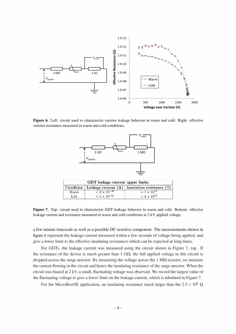
For GDTs, the leakage current was measured using the circuit shown in Figure 7, top. Ifthe resistance of the device is much greater than 1 GΩ, the full applied voltage in this circuit isdropped across the surge arrestor. By measuring the voltage across the 1 MΩ resistor, we measurethe current flowing in the circuit and hence the insulating resistance of the surge arrestor. When thecircuit was biased at 2 kV, a small, fluctuating voltage was observed. We record the largest value ofthe fluctuating voltage to give a lower limit on the leakage current, which is tabulated in Figure 7.
For the MicroBooNE application, an insulating resistance much larger than the 2.5× 10⁸ Ω
– 8 –
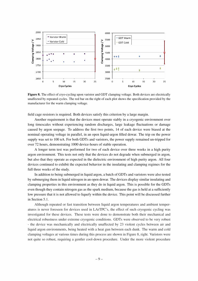
Figure 8. The effect of cryo-cycling upon varistor and GDT clamping voltage. Both devices are electricallyunaffected by repeated cycles. The red bar on the right of each plot shows the specification provided by themanufacturer for the warm clamping voltage.
field cage resistors is required. Both devices satisfy this criterion by a large margin.Another requirement is that the devices must operate stably in a cryogenic environment over
long timescales without experiencing random discharges, large leakage fluctuations or damagecaused by argon seepage. To address the first two points, 14 of each device were biased at thenominal operating voltage in parallel, in an open liquid-argon filled dewar. The trip on the powersupply was set to 100 nA. For both GDTs and varistors, the power supply remained un-tripped forover 72 hours, demonstrating 1000 device-hours of stable operation.
A longer term test was performed for two of each device over three weeks in a high purityargon environment. This tests not only that the devices do not degrade when submerged in argon,but also that they operate as expected in the dielectric environment of high purity argon. All fourdevices continued to exhibit the expected behavior in the insulating and clamping regimes for thefull three weeks of the study.
In addition to being submerged in liquid argon, a batch of GDTs and varistors were also testedby submerging them in liquid nitrogen in an open dewar. The devices display similar insulating andclamping properties in this environment as they do in liquid argon. This is possible for the GDTseven though they contain nitrogen gas as the spark medium, because the gas is held at a sufficientlylow pressure that it is not allowed to liquefy within the device. This point will be discussed furtherin Section 5.1.
Although repeated or fast transition between liquid argon temperatures and ambient temper-atures is never foreseen for devices used in LArTPC’s, the effect of such cryogenic cycling wasinvestigated for these devices. These tests were done to demonstrate both their mechanical andelectrical robustness under extreme cryogenic conditions. GDTs were observed to be very robust- the device was mechanically and electrically unaffected by 23 violent cycles between air andliquid argon environments, being heated with a heat gun between each dunk. The warm and coldclamping voltages at various times during this process are shown in Figure 8, right. Varistors werenot quite so robust, requiring a gentler cool-down procedure. Under the more violent procedure
– 9 –
VHV C
HV relay
RBleed
VRelay
Relay switch
HV cage
1 GΩ
Test device
Liquid Argon Dewar
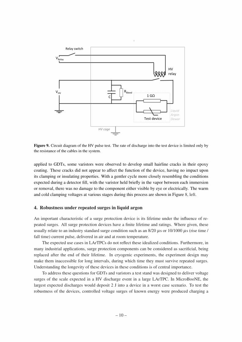
Figure 9. Circuit diagram of the HV pulse test. The rate of discharge into the test device is limited only bythe resistance of the cables in the system.
applied to GDTs, some varistors were observed to develop small hairline cracks in their epoxycoating. These cracks did not appear to affect the function of the device, having no impact uponits clamping or insulating properties. With a gentler cycle more closely resembling the conditionsexpected during a detector fill, with the varistor held briefly in the vapor between each immersionor removal, there was no damage to the component either visible by eye or electrically. The warmand cold clamping voltages at various stages during this process are shown in Figure 8, left.
4. Robustness under repeated surges in liquid argon
An important characteristic of a surge protection device is its lifetime under the influence of re-peated surges. All surge protection devices have a finite lifetime and ratings. Where given, theseusually relate to an industry standard surge condition such as an 8/20 µs or 10/1000 µs (rise time /fall time) current pulse, delivered in air and at room temperature.
The expected use cases in LArTPCs do not reflect these idealized conditions. Furthermore, inmany industrial applications, surge protection components can be considered as sacrificial, beingreplaced after the end of their lifetime. In cryogenic experiments, the experiment design maymake them inaccessible for long intervals, during which time they must survive repeated surges.Understanding the longevity of these devices in these conditions is of central importance.
To address these questions for GDTs and varistors a test stand was designed to deliver voltagesurges of the scale expected in a HV discharge event in a large LArTPC. In MicroBooNE, thelargest expected discharges would deposit 2 J into a device in a worst case scenario. To test therobustness of the devices, controlled voltage surges of known energy were produced charging a
– 10 –
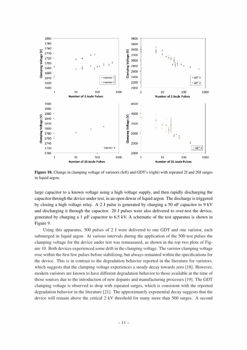
Figure 10. Change in clamping voltage of varistors (left) and GDT’s (right) with repeated 2J and 20J surgesin liquid argon.
large capacitor to a known voltage using a high voltage supply, and then rapidly discharging thecapacitor through the device under test, in an open dewar of liquid argon. The discharge is triggeredby closing a high voltage relay. A 2 J pulse is generated by charging a 50 nF capacitor to 9 kVand discharging it through the capacitor. 20 J pulses were also delivered to over-test the device,generated by charging a 1 µF capacitor to 6.5 kV. A schematic of the test apparatus is shown inFigure 9.
Using this apparatus, 500 pulses of 2 J were delivered to one GDT and one varistor, eachsubmerged in liquid argon. At various intervals during the application of the 500 test pulses theclamping voltage for the device under test was remeasured, as shown in the top two plots of Fig-ure 10. Both devices experienced some drift in the clamping voltage. The varistor clamping voltagerose within the first few pulses before stabilizing, but always remained within the specifications forthe device. This is in contrast to the degradation behavior reported in the literature for varistors,which suggests that the clamping voltage experiences a steady decay towards zero [18]. However,modern varistors are known to have different degradation behavior to those available at the time ofthose sources due to the introduction of new dopants and manufacturing processes [19]. The GDTclamping voltage is observed to drop with repeated surges, which is consistent with the reporteddegradation behavior in the literature [21]. The approximately exponential decay suggests that thedevice will remain above the critical 2 kV threshold for many more than 500 surges. A second
– 11 –
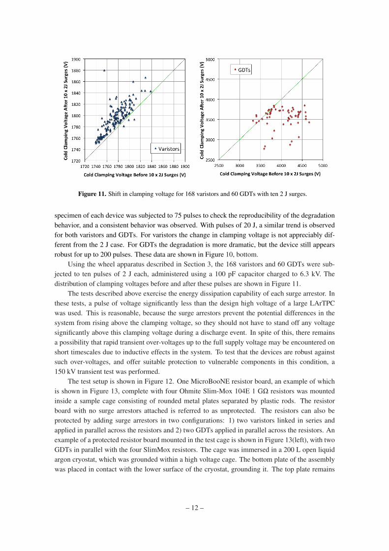
Figure 11. Shift in clamping voltage for 168 varistors and 60 GDTs with ten 2 J surges.
specimen of each device was subjected to 75 pulses to check the reproducibility of the degradationbehavior, and a consistent behavior was observed. With pulses of 20 J, a similar trend is observedfor both varistors and GDTs. For varistors the change in clamping voltage is not appreciably dif-ferent from the 2 J case. For GDTs the degradation is more dramatic, but the device still appearsrobust for up to 200 pulses. These data are shown in Figure 10, bottom.
Using the wheel apparatus described in Section 3, the 168 varistors and 60 GDTs were sub-jected to ten pulses of 2 J each, administered using a 100 pF capacitor charged to 6.3 kV. Thedistribution of clamping voltages before and after these pulses are shown in Figure 11.
The tests described above exercise the energy dissipation capability of each surge arrestor. Inthese tests, a pulse of voltage significantly less than the design high voltage of a large LArTPCwas used. This is reasonable, because the surge arrestors prevent the potential differences in thesystem from rising above the clamping voltage, so they should not have to stand off any voltagesignificantly above this clamping voltage during a discharge event. In spite of this, there remainsa possibility that rapid transient over-voltages up to the full supply voltage may be encountered onshort timescales due to inductive effects in the system. To test that the devices are robust againstsuch over-voltages, and offer suitable protection to vulnerable components in this condition, a150 kV transient test was performed.
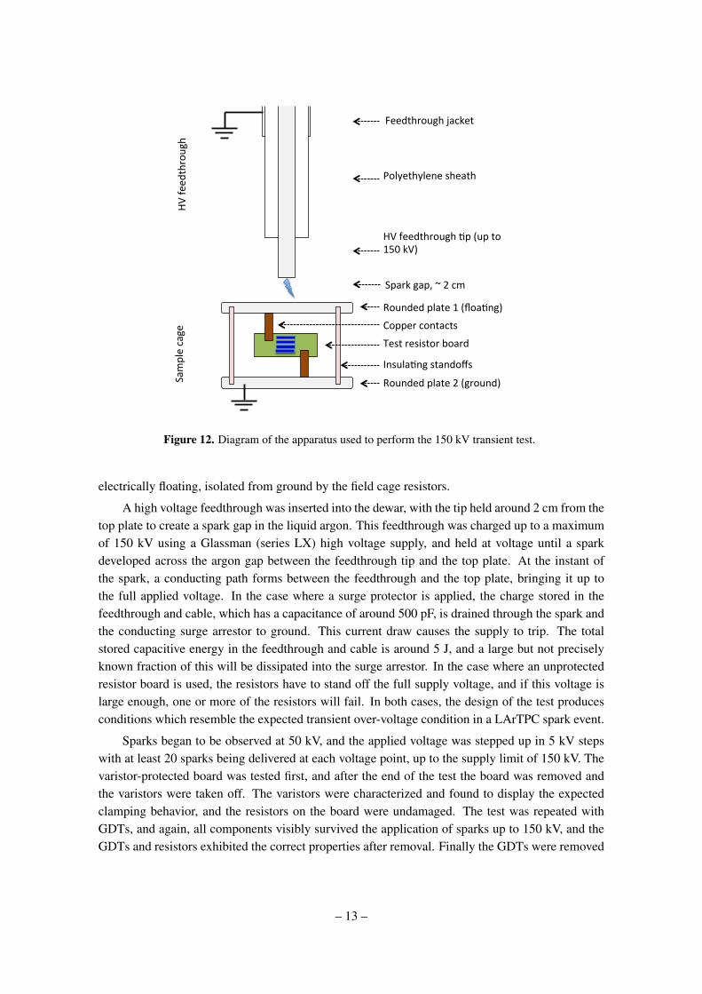
The test setup is shown in Figure 12. One MicroBooNE resistor board, an example of whichis shown in Figure 13, complete with four Ohmite Slim-Mox 104E 1 GΩ resistors was mountedinside a sample cage consisting of rounded metal plates separated by plastic rods. The resistorboard with no surge arrestors attached is referred to as unprotected. The resistors can also beprotected by adding surge arrestors in two configurations: 1) two varistors linked in series andapplied in parallel across the resistors and 2) two GDTs applied in parallel across the resistors. Anexample of a protected resistor board mounted in the test cage is shown in Figure 13(left), with twoGDTs in parallel with the four SlimMox resistors. The cage was immersed in a 200 L open liquidargon cryostat, which was grounded within a high voltage cage. The bottom plate of the assemblywas placed in contact with the lower surface of the cryostat, grounding it. The top plate remains
– 12 –
HV feedthrough -p (up to 150 kV)
Polyethylene sheath
Feedthrough jacket
Rounded plate 1 (floa-ng)
HV fe
edthrough
Sample cage
Rounded plate 2 (ground)
Copper contacts
Test resistor board
Insula-ng standoffs
Spark gap, ~ 2 cm
Figure 12. Diagram of the apparatus used to perform the 150 kV transient test.
electrically floating, isolated from ground by the field cage resistors.
A high voltage feedthrough was inserted into the dewar, with the tip held around 2 cm from thetop plate to create a spark gap in the liquid argon. This feedthrough was charged up to a maximumof 150 kV using a Glassman (series LX) high voltage supply, and held at voltage until a sparkdeveloped across the argon gap between the feedthrough tip and the top plate. At the instant ofthe spark, a conducting path forms between the feedthrough and the top plate, bringing it up tothe full applied voltage. In the case where a surge protector is applied, the charge stored in thefeedthrough and cable, which has a capacitance of around 500 pF, is drained through the spark andthe conducting surge arrestor to ground. This current draw causes the supply to trip. The totalstored capacitive energy in the feedthrough and cable is around 5 J, and a large but not preciselyknown fraction of this will be dissipated into the surge arrestor. In the case where an unprotectedresistor board is used, the resistors have to stand off the full supply voltage, and if this voltage islarge enough, one or more of the resistors will fail. In both cases, the design of the test producesconditions which resemble the expected transient over-voltage condition in a LArTPC spark event.
Sparks began to be observed at 50 kV, and the applied voltage was stepped up in 5 kV stepswith at least 20 sparks being delivered at each voltage point, up to the supply limit of 150 kV. Thevaristor-protected board was tested first, and after the end of the test the board was removed andthe varistors were taken off. The varistors were characterized and found to display the expectedclamping behavior, and the resistors on the board were undamaged. The test was repeated withGDTs, and again, all components visibly survived the application of sparks up to 150 kV, and theGDTs and resistors exhibited the correct properties after removal. Finally the GDTs were removed
– 13 –
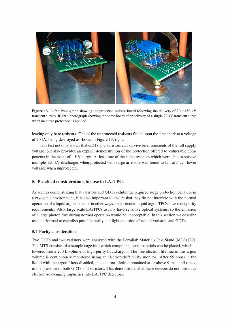
Figure 13. Left : Photograph showing the protected resistor board following the delivery of 20× 150 kVtransient surges. Right : photograph showing the same board after delivery of a single 70 kV transient surgewhen no surge protection is applied.
leaving only bare resistors. One of the unprotected resistors failed upon the first spark at a voltageof 70 kV, being destroyed as shown in Figure 13, right.
This test not only shows that GDTs and varistors can survive brief transients of the full supplyvoltage, but also provides an explicit demonstration of the protection offered to vulnerable com-ponents in the event of a HV surge. At least one of the same resistors which were able to survivemultiple 150 kV discharges when protected with surge arrestors was found to fail at much lowervoltages when unprotected.
5. Practical considerations for use in LArTPCs
As well as demonstrating that varistors and GDTs exhibit the required surge protection behavior ina cryogenic environment, it is also important to ensure that they do not interfere with the normaloperation of a liquid argon detector in other ways. In particular, liquid argon TPCs have strict purityrequirements. Also, large scale LArTPCs usually have sensitive optical systems, so the emissionof a large photon flux during normal operation would be unacceptable. In this section we describetests performed to establish possible purity and light emission effects of varistors and GDTs.
5.1 Purity considerations
Two GDTs and two varistors were analyzed with the Fermilab Materials Test Stand (MTS) [22].The MTS consists of a sample cage into which components and materials can be placed, which islowered into a 250 L volume of high purity liquid argon. The free electron lifetime in this argonvolume is continuously monitored using an electron-drift purity monitor. After 55 hours in theliquid with the argon filters disabled, the electron lifetime remained at or above 9 ms at all times,in the presence of both GDTs and varistors. This demonstrates that these devices do not introduceelectron-scavenging impurities into LArTPC detectors.
– 14 –
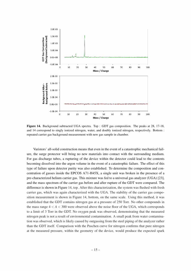
Figure 14. Background subtracted UGA spectra. Top : GDT gas composition. The peaks at 28, 17-18,and 14 correspond to singly ionized nitrogen, water, and doubly ionized nitrogen, respectively. Bottom :repeated carrier gas background measurement with new gas sample in chamber.
Varistors’ all-solid construction means that even in the event of a catastrophic mechanical fail-ure, the surge protector will bring no new materials into contact with the surrounding medium.For gas discharge tubes, a rupturing of the device within the detector could lead to the contentsbecoming dissolved into the argon volume in the event of a catastrophic failure. The effect of thistype of failure upon detector purity was also established. To determine the composition and con-centration of gasses inside the EPCOS A71-H45X, a single unit was broken in the presence of apre-characterized helium carrier gas. This mixture was fed to a universal gas analyzer (UGA) [23],and the mass spectrum of the carrier gas before and after rupture of the GDT were compared. Thedifference is shown in Figure 14, top. After this characterization, the system was flushed with freshcarrier gas, which was again characterized with the UGA. The stability of the carrier gas compo-sition measurement is shown in Figure 14, bottom, on the same scale. Using this method, it wasestablished that the GDT contains nitrogen gas at a pressure of 250 Torr. No other compounds inthe mass range 4 < A < 300 were observed above the noise floor of the UGA, which correspondsto a limit of 3 Torr in the GDT. No oxygen peak was observed, demonstrating that the measurednitrogen peak is not a result of environmental contamination. A small peak from water contamina-tion was observed, which is likely caused by outgassing from the steel piping of the analyzer ratherthan the GDT itself. Comparison with the Paschen curve for nitrogen confirms that pure nitrogenat the measured pressure, within the geometry of the device, would produce the expected spark
– 15 –
1.E-‐05
1.E-‐04
1.E-‐03
1.E-‐02
1.E-‐01
1.E+00
1.E+01
1.E+02
1.E+03
0 50 100 150 200 250 300 350 400
Pressure / M
Pa
Temperature / K
solid
liquid
gas
STP
Room Temp
LAr
LN2
Cri(cal Point
Triple Point
Room$temp$
LAr$
LN2$
~Our$m
easuremen
t$supercri6cal
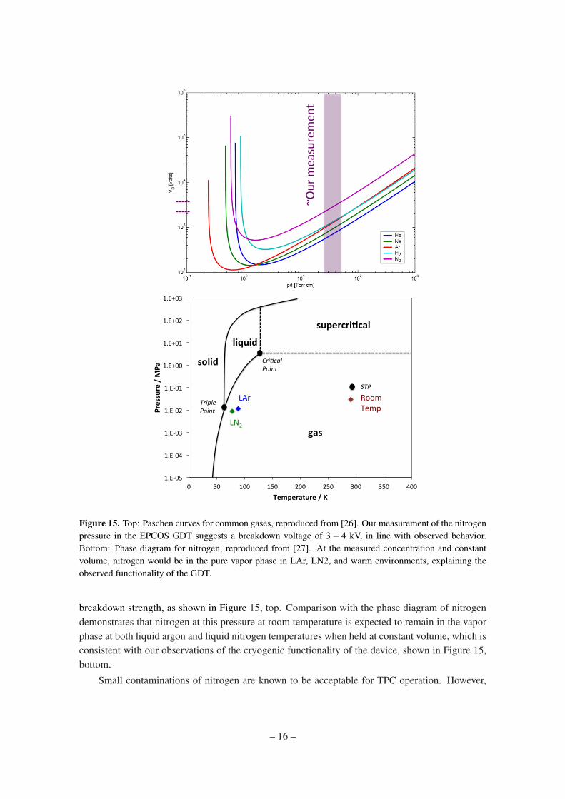
Figure 15. Top: Paschen curves for common gases, reproduced from [26]. Our measurement of the nitrogenpressure in the EPCOS GDT suggests a breakdown voltage of 3− 4 kV, in line with observed behavior.Bottom: Phase diagram for nitrogen, reproduced from [27]. At the measured concentration and constantvolume, nitrogen would be in the pure vapor phase in LAr, LN2, and warm environments, explaining theobserved functionality of the GDT.
breakdown strength, as shown in Figure 15, top. Comparison with the phase diagram of nitrogendemonstrates that nitrogen at this pressure at room temperature is expected to remain in the vaporphase at both liquid argon and liquid nitrogen temperatures when held at constant volume, which isconsistent with our observations of the cryogenic functionality of the device, shown in Figure 15,bottom.
Small contaminations of nitrogen are known to be acceptable for TPC operation. However,
– 16 –

19.20&
19.25&
19.30&
19.35&
19.40&
19.45&
19.50&
19.55&
19.60&
HV&off&
HV&off&
2kV,&GDT
&1&
2kV,&GDT
&1&
HV&off&
1kV,&Varistor&1&
1kV,&Varistor,&1&
HV&Off&
HV&Off&
2kV,&GDT
&2&&
2kV,&GDT
&2&&
HV&Off&
1kV,&Varistor,&2&
1kv,&Varistor,&2&
HV&Off&
Rate%/%KHz
%
Average dark rate
Figure 16. The rate of a single photoelectron trigger with different devices held at nominal high voltagearound 15 cm from an LBNE lightguide detector
nitrogen at the part-per-million level can have detrimental effects upon liquid argon scintillationlight collection [24, 25]. Our measurements show that a single GDT, which has a volume of ap-proximately 0.4 cm3, contains 6×10⁻⁶ mol of nitrogen gas. As an example, if one GDT were toleak into the MicroBooNE detector, which contains 170 tons of liquid argon, this would introducea nitrogen contamination of around 1.4× 10⁻¹². This is far below nitrogen concentrations whichare problematic for scintillation light collection.
5.2 Light emission
The devices under consideration are to be operated at a nominal voltage of 2 kV (this voltagewould be applied across a single GDT, or two or more varistors in series). In past detectors, someelectronic components have been reported to glow when HV is applied [28]. In order to establishwhether there is light emission associated with the operation of GDTs and varistors at nominalvoltages, two of each were installed alongside tests of prototype optical detectors for the LBNEexperiment [29], in the TallBo optical test cryostat at Fermilab [30].
The prototype optical detectors consist of an acrylic light guide coated in a wavelength shiftingTPB coating [29]. This is coupled to three silicon photomultiplier (SiPM) detectors which havetheir signals fed to a shaper. For this test, the shaped signal from one SiPM was viewed usingan oscilloscope. Binning the pulse amplitudes shows a clear separation of each N photoelectronpeaks up to at least 20. The detectors have an estimated average collection efficiency of O(0.03%)[31] for 128 nm liquid argon scintillation light. A trigger was set at 10 mV, which is below thesingle photoelectron level of 12 mV, and the single photoelectron trigger rate was determined bycounting the number of triggers in five minutes. The rate when no voltage was supplied to anysurge protector was 19.44±0.02 kHz, which includes both thermionic SiPM noise and the promptand late scintillation signals from cosmic ray muons passing through the detector. The rate was
– 17 –
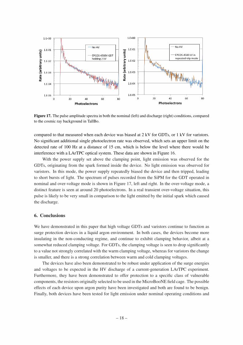
Figure 17. The pulse amplitude spectra in both the nominal (left) and discharge (right) conditions, comparedto the cosmic ray background in TallBo.
compared to that measured when each device was biased at 2 kV for GDTs, or 1 kV for varistors.No significant additional single photoelectron rate was observed, which sets an upper limit on thedetected rate of 100 Hz at a distance of 15 cm, which is below the level where there would beinterference with a LArTPC optical system. These data are shown in Figure 16.
With the power supply set above the clamping point, light emission was observed for theGDTs, originating from the spark formed inside the device. No light emission was observed forvaristors. In this mode, the power supply repeatedly biased the device and then tripped, leadingto short bursts of light. The spectrum of pulses recorded from the SiPM for the GDT operated innominal and over-voltage mode is shown in Figure 17, left and right. In the over-voltage mode, adistinct feature is seen at around 20 photoelectrons. In a real transient over-voltage situation, thispulse is likely to be very small in comparison to the light emitted by the initial spark which causedthe discharge.
6. Conclusions
We have demonstrated in this paper that high voltage GDTs and varistors continue to function assurge protection devices in a liquid argon environment. In both cases, the devices become moreinsulating in the non-conducting regime, and continue to exhibit clamping behavior, albeit at asomewhat reduced clamping voltage. For GDTs, the clamping voltage is seen to drop significantlyto a value not strongly correlated with the warm clamping voltage, whereas for varistors the changeis smaller, and there is a strong correlation between warm and cold clamping voltages.
The devices have also been demonstrated to be robust under application of the surge energiesand voltages to be expected in the HV discharge of a current-generation LArTPC experiment.Furthermore, they have been demonstrated to offer protection to a specific class of vulnerablecomponents, the resistors originally selected to be used in the MicroBooNE field cage. The possibleeffects of each device upon argon purity have been investigated and both are found to be benign.Finally, both devices have been tested for light emission under nominal operating conditions and
– 18 –
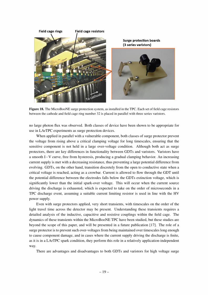
Figure 18. The MicroBooNE surge protection system, as installed in the TPC. Each set of field cage resistorsbetween the cathode and field cage ring number 32 is placed in parallel with three series varistors.
no large photon flux was observed. Both classes of device have been shown to be appropriate foruse in LArTPC experiments as surge protection devices.
When applied in parallel with a vulnerable component, both classes of surge protector preventthe voltage from rising above a critical clamping voltage for long timescales, ensuring that thesensitive component is not held in a large over-voltage condition. Although both act as surgeprotectors, there are key differences in functionality between GDTs and varistors. Varistors havea smooth I−V curve, free from hysteresis, producing a gradual clamping behavior. An increasingcurrent supply is met with a decreasing resistance, thus preventing a large potential difference fromevolving. GDTs, on the other hand, transition discretely from the open to conductive state when acritical voltage is reached, acting as a crowbar. Current is allowed to flow through the GDT untilthe potential difference between the electrodes falls below the GDTs extinction voltage, which issignificantly lower than the initial spark-over voltage. This will occur when the current sourcedriving the discharge is exhausted, which is expected to take on the order of microseconds in aTPC discharge event, assuming a suitable current limiting resistor is used in line with the HVpower supply.
Even with surge protectors applied, very short transients, with timescales on the order of thelight travel time across the detector may be present. Understanding these transients requires adetailed analysis of the inductive, capacitive and resistive couplings within the field cage. Thedynamics of these transients within the MicroBooNE TPC have been studied, but these studies arebeyond the scope of this paper, and will be presented in a future publication [17]. The role of asurge protector is to prevent such over-voltages from being maintained over timescales long enoughto cause component damage, and in cases where the current supply driving the discharge is finite,as it is in a LArTPC spark condition, they perform this role in a relatively application-independentway.
There are advantages and disadvantages to both GDTs and varistors for high voltage surge
– 19 –
protection. In particular, easily mountable varistors are not commercially available in the appropri-ate voltage range for typical LArTPC applications, so several devices must be used in series. Thisrequires more solder connections and mounting hardware than in the case of a GDT, where a singleunit may be mounted directly in parallel with the vulnerable component to be protected. On theother hand, the gradual clamping behavior and well defined I−V curve of varistors makes it easierto model the dynamics of the field cage in surge conditions using software such as SPICE [32].
As a result of this work, a varistor based surge protection system was installed in parallelwith the MicroBooNE TPC resistor chain between the the cathode and the thirty-two nearest fieldcage rings. Sets of three series varistors, having a combined clamping voltage of 5.26± 0.04 kV,were mounted on G10 boards and affixed using brass contacts to the mount points of the field cageresistor boards on the TPC frame. A picture is shown in Figure 18.
As well as being suitable for this specific application, this work demonstrates generally thatGDTs and varistors continue to act as surge protection devices in liquid argon environments. Assuch, both classes of device may find wider applications in electrical protection of sensitive com-ponents in LArTPC detectors.
Acknowledgements
We thank Walter Jaskierny for assistance in the design and implementation of safe and conclusivehigh voltage tests, and Jonathan Woodworth of ArrestorWorks for helpful consultations on indus-trial use of varistors. We thank Henning Back helping us to perform gas analysis using a UGAwhich is part of the low-radioactivity argon purification project, Stuart Mufson and Denver Whit-tington for the equipment and expertise used to measure light emission from devices in the Bo teststand, Stephen Pordes for allowing us access to the MTS and other facilities at the Proton AssemblyBuilding, Ewa Skup for operating the MTS, and Sarah Lockwitz for setting up the MicroBooNEHV feedthrough test stand. We also thank our MicroBooNE collaborators for giving helpful feed-back at all stages of this work, in particular Linda Bagby, Regina Rameika, Jennifer Raaf, AnneSchukraft, and Michele Weber.
This work was supported by the Fermi National Accelerator Laboratory, which is operatedby the Fermi Research Alliance, LLC under Contract No. De-AC02- 07CH11359 with the UnitedStates Department of Energy. The surge protection components under test, and the work by BJPJand JMC, were funded by the National Science Foundation grant PHY-1205175. JA is supportedby National Science Foundation grant PHY-1068553. SG is supported by the Department of En-ergy through grant DE-FG03-99ER41093 and JMSJ through grant DE-SC0011784. TS acknowl-edges the support of the Swiss National Science Foundation. JZ is supported by the University ofChicago.
References
[1] G. Raselli, “ICARUS T600: Status and perspectives of liquid-argon technology for neutrino physics,”Nuovo Cim., vol. C036, no. 01, pp. 243–246, 2013.
[2] C. Adams et al., “Scientific Opportunities with the Long-Baseline Neutrino Experiment,” 2013.
– 20 –
[3] H. Chen et al., “Proposal for a New Experiment Using the Booster and NuMI Neutrino Beamlines:MicroBooNE,” 2007.
[4] A. de Gouvea et al., “Working Group Report: Neutrinos,” 2013.
[5] S. Agarwalla et al., “The mass-hierarchy and CP-violation discovery reach of the LBNOlong-baseline neutrino experiment,” 2013.
[6] A. Zani, “The WArP Experiment: A Double-Phase Argon Detector for Dark Matter Searches,”Adv.High Energy Phys., vol. 2014, p. 205107, 2014.
[7] K. Rielage, “Status and prospects of the MiniCLEAN dark matter experiment,” AIP Conf.Proc.,vol. 1441, pp. 518–520, 2012.
[8] M. Boulay, “DEAP-3600 Dark Matter Search at SNOLAB,” J.Phys.Conf.Ser., vol. 375, p. 012027,2012.
[9] M. Bossa, “DarkSide-50, a background free experiment for dark matter searches,” JINST, vol. 9,p. C01034, 2014.
[10] A. Badertscher, F. Bay, N. Bourgeois, C. Cantini, A. Curioni, et al., “ArDM: first results fromunderground commissioning,” JINST, vol. 8, p. C09005, 2013.
[11] MicroBooNE Collaboration, “Measurements of hv breakdown strength in argon with the hvc teststand,” In preparation.
[12] A. Blatter, A. Ereditato, C.-C. Hsu, S. Janos, I. Kreslo, et al., “Experimental study of electricbreakdowns in liquid argon at centimeter scale,” JINST, vol. 9, p. P04006, 2014.
[13] F. Bay, C. Cantini, S. Murphy, F. Resnati, A. Rubbia, et al., “Evidence of electric breakdown inducedby bubbles in liquid argon,” 2014.
[14] D. Swan and T. Lewis J.Electrochem.Soc., vol. 107, no. 180, 1960.
[15] Panosonic Corporaiton, “ZNT Transient Surge Absorbers.”http://industrial.panasonic.com/www-data/pdf/AWA0000/AWA0000CE2.pdf.
[16] EPCOS, “EPCOS Product Profile 2013: Surge Arresters and Switching Spark Gaps.”http://www.epcos.com/blob/174146/download/5/
ueberspannungsableiter-und-schaltfunkenstrecken.pdf.
[17] MicroBooNE Collaboration, “The MicroBooNE Detector,” In preparation.
[18] T. K. Gupta, “Application of zinc oxide varistors,” Journal of the American Ceramic Society, vol. 73,no. 7, pp. 1817–1840, 1990.
[19] J. Woodworth of ArrestorWorks. Personal Communication.
[20] EPCOS, “EPCOS A71-H45X Data sheet.”http://www.epcos.com/inf/100/ds/a71h45xx2590.pdf.
[21] Bourns Corporation, “First Principles of a Gas Discharge Tube (GDT) Primary Protector.”http://www.bourns.com/pdfs/bourns_gdt_whitepaper.pdf.
[22] B. Rebel, M. Adamowski, W. Jaskierny, H. Jostlein, C. Kendziora, et al., “Results from the Fermilabmaterials test stand and status of the liquid argon purity demonstrator,” J.Phys.Conf.Ser., vol. 308,p. 012023, 2011.
[23] Stanford Research Systems, “Universal gas analyzer manual.”http://www.thinksrs.com/downloads/PDFs/Manuals/UGAm.pdf.
– 21 –
[24] R. Acciarri et al., “Effects of Nitrogen contamination in liquid Argon,” JINST, vol. 5, p. P06003,2010.
[25] B. Jones, C. Chiu, J. Conrad, C. Ignarra, T. Katori, and M. Toups, “A measurement of the absorptionof liquid argon scintillation light by dissolved nitrogen at the part-per-million level,” JINST, vol. 8,no. P07011, 2013.
[26] Lieberman and Lichtenberg, “Principles of plasma discharges.” Wiley 2005.
[27] Wolfram Alpha, “Phase diagram for nitrogen.” www.wolframalpha.com.
[28] M. Hofmann, “Liquid scintillators and liquefied rare gases for particle detectorsbackground-determination in double chooz and scintillation properties of liquid argon,” Master’sthesis, Technische Universitat Munchen, 9 2012.
[29] B. Baptista, L. Bugel, C. Chiu, J. Conrad, C. Ignarra, et al., “Benchmarking TPB-coated Light Guidesfor Liquid Argon TPC Light Detection Systems,” 2012.
[30] B. Jones, “Results from the Bo Liquid Argon Scintillation Test Stand at Fermilab,” JINST, vol. 8,p. C09003, 2013.
[31] D. Whittington Private communication.
[32] L. W. Nagel and D. Pederson, “Spice (simulation program with integrated circuit emphasis),” Tech.Rep. UCB/ERL M382, EECS Department, University of California, Berkeley, Apr 1973.
– 22 –