Embed Size (px)
Citation preview
Low Voltage Power Supply Incorporating
Cerami TransformerMasatosi Imori and Yasumasa Kanada
Authors thanks Messrs Masafumi Katsuno and Yoichi Mamiya at TOKIN Corporation for providing stepdown ceranmc transformers
Information Technology Center, University of Tokyo
Merits of Ceramic Transformer
• Power density of the ceramic transformer is more than 5 times higher than that of the magnetic transformer.
• The ceramic transformer is operated at high frequencies where the magnetic transformer can not operate efficiently.
• A power module can be reduced in size by employing the ceramic transformer.
Amplitude Ratio
• A carrier drives the ceramic transformer.
• The carrier at the input is transformed to the one at the output
• The ceramic transformer includes internal resonance circuit.
• The amplitude of the carrier at the input is changed at the output, with the input to output voltage ratio of the amplitude being an amplitude ratio.
• The amplitude ratio shows a resonance as a function of the driving frequency: the frequency of the carrier.
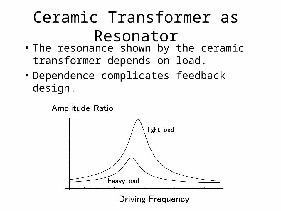
Ceramic Transformer as Resonator• The resonance shown by the ceramic
transformer depends on load.
• Dependence complicates feedback design.
Ground Isolation
• It is important for a power supply to isolate ground between the primary and the secondary.
• When energy is stored in inductance, it might be difficult to implement ground isolation without the magnetic transformer.
• When energy is stored in capacitance, is it possible to realize ground isolation without the ceramic transformer?
4 Terminal Ceramic Transformer
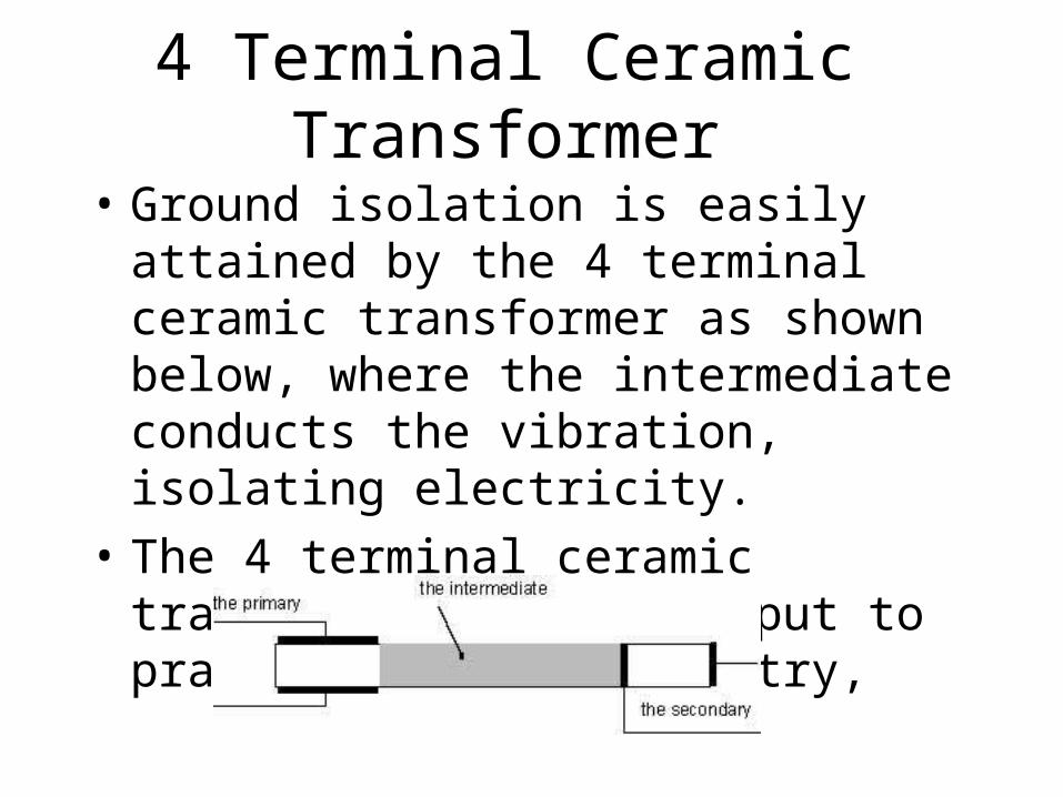
• Ground isolation is easily attained by the 4 terminal ceramic transformer as shown below, where the intermediate conducts the vibration, isolating electricity.
• The 4 terminal ceramic transformer has been put to practical use in industry,
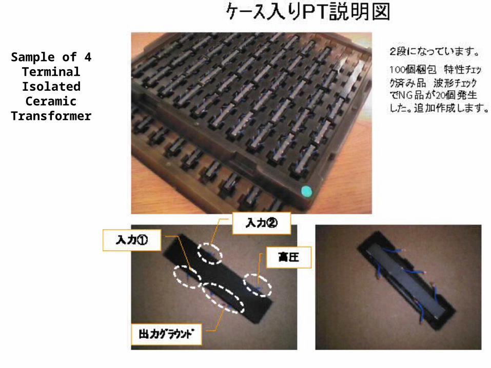
Sample of 4 Terminal
Isolated Ceramic Transformer

Tokin Corp. has provided the stepdown ceramic transformers.
• We began to design the stepdown DC-DC converter employing the ceramic transformer.
• The converter has been extensively simulated by OrCAD and SCAT.
• Implementation of the converter is at the beginning stage of artwork.
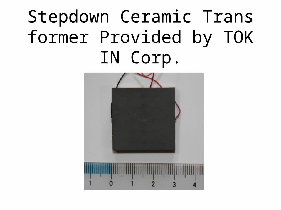
Stepdown Ceramic Transformer Provided by TOKIN Corp.
Capability of Stepdown Ceramic Transformer
• The stepdown transformer is capable of converting dc 380 V to dc 17 V with the output current of 2 A.
• Rating of the transformer is about 34W.
• The frequency at which the transformer is driven move to the resonance frequency as the increase of the load current.
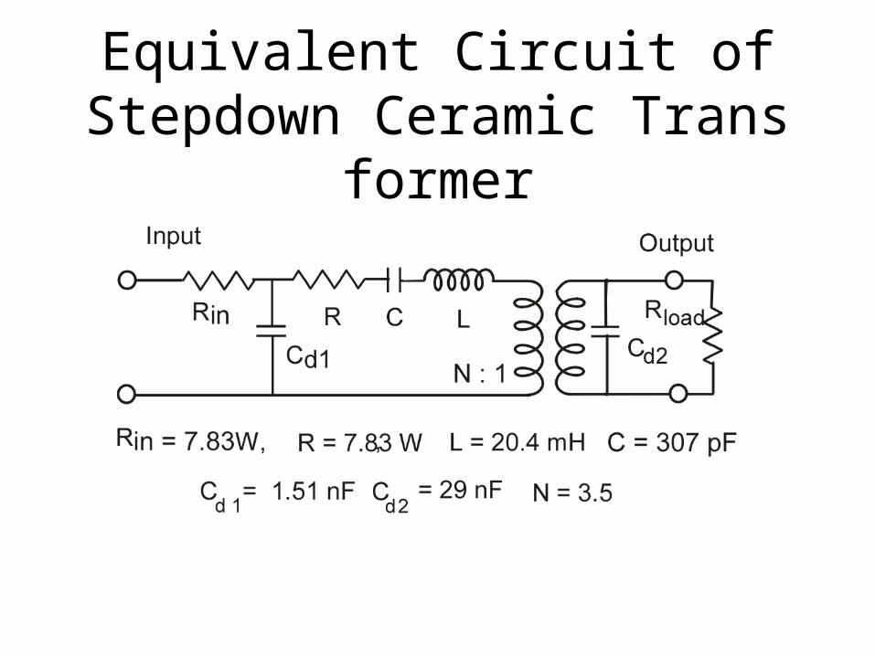
Equivalent Circuit of Stepdown Ceramic Transformer
How to drive the ceramic transformer
• A FET full bridge drives the ceramic transformer or generates the carrier.
• The full bridge operates in a phase shift mode.• A pair of gate pulses drives a half bridge.• Two pairs of gate pulses share the driving
frequency of the carrier,• Phase shift between the pairs controls the
amplitude of the carrier
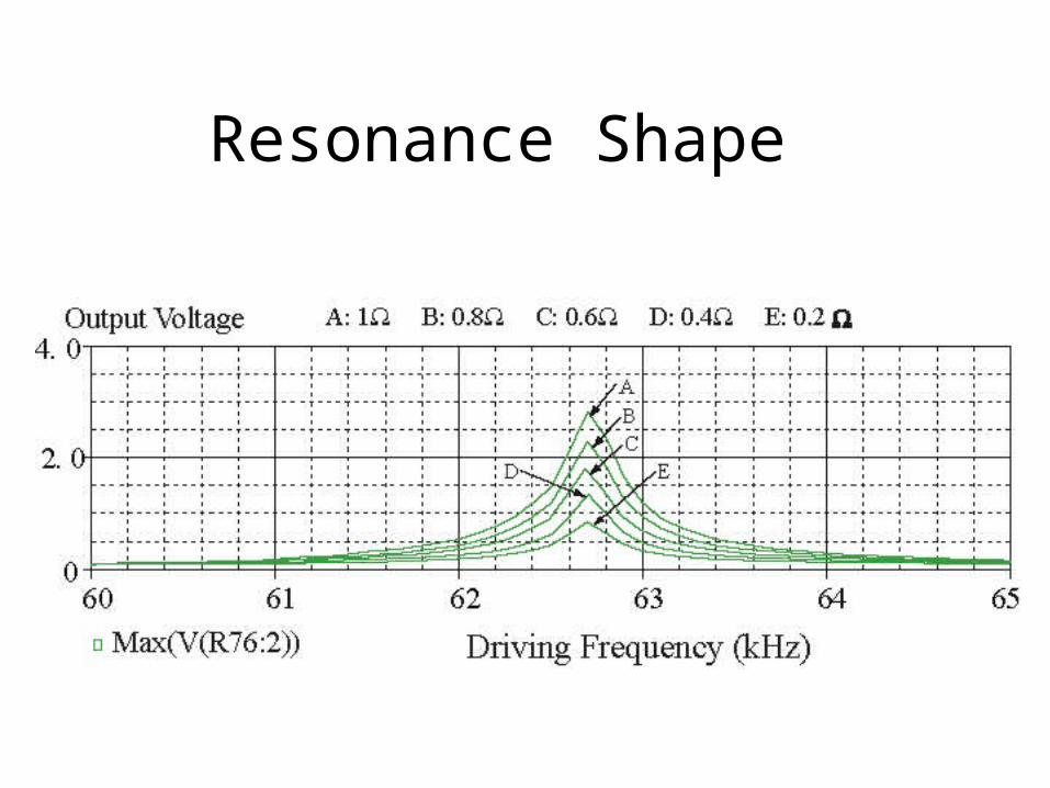
Resonance Shape
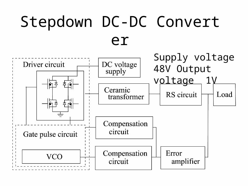
Stepdown DC-DC Converter
Supply voltage 48V Output voltage 1V
Frequency Modulation• The output of the error amplifier is supplied to
the compensation circuit.• Its transfer function is similar to the one of the
high voltage power supply.• The carrier which drives the ceramic
transformer is modulated in frequency by the output of the compensation circuit.
• The ceramic transformer convert the modulation from frequency modulation at the input to amplitude modulation at the output.
Amplitude Modulation
• The output of the error amplifier is supplied to the driver circuit through the compensation circuit which cancels the delay caused by the RS circuit.
• The output of the compensation circuit controls the phase shift between the pairs, and then controls the amplitude of the carrier
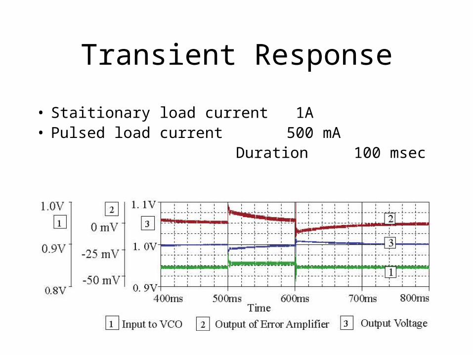
Transient Response
• Staitionary load current 1A• Pulsed load current 500 mA Duration 100 msec
What limits bandwidth for feedback?
• Bandwidth of the ceramic transformer. Let δ be defined by ωr / 2Q, the bandwidth is roughly approximated by δ
• Output impedance of the ceramic transformer.
• If the resonance frequency is ten times high, the transient response will be improved by a factor of ten.
Complying With Large and Rapid Load Change
• The stepdown converter can not follow, for example, a full load change within 1 μsec.
• A double-layered capacitor could buffer such the large and rapid load change so as to suit the stepdown converter
• Is the double-layered capacitor available in the radiation-hard environment?


![, Kyi Moe , Yasumasa Obo , Shiniti Obo , Aung Zaw Htwe ... · position of crop residues and physicochemical properties of soil [1]. Seaweed extract has been used as a source of organic](https://img.pdfslide.us/doc/110x75/5e67b58375580b04b601f443/-kyi-moe-yasumasa-obo-shiniti-obo-aung-zaw-htwe-position-of-crop-residues.jpg)