Embed Size (px)
Citation preview

12
Low-thrust Propulsion Technologies, Mission Design, and Application
John W. Dankanich Gray Research Inc.
U.S.A.
1. Introduction
Electric propulsion has been widely accepted for station-keeping and final orbit insertion of
commercial satellites. NASA, JAXA, and ESA have all used primary electric propulsion
systems for science missions. Electric propulsion systems have been recently developed with
a significant increase in performance and ability to process large amounts of onboard solar
power. While the use of electric propulsion offers significant performance gains, it is not
appropriate for all missions, has limitations, and the trajectories have characteristics that
may be counterintuitive to those unfamiliar with low-thrust trajectory design. This chapter
describes recent U.S. technology investments in electric propulsion thrusters with emphasis
on mission application and low-thrust mission design for interplanetary trajectories and
geosynchronous transfer using primary electric propulsion.
2. Overview of electric propulsion technologies
Unlike chemical propulsion, which is limited to the energy available through the
decomposition or combustion of molecular compounds, electric propulsion makes use of
energy from an external source, typically solar power, to electrically accelerate the
propellant to higher energies. The efficiency of momentum transfer is often described in
terms of specific impulse which is proportional to the average exhaust velocity in the thrust
direction.
荊鎚椎 噺 懸帳掴朕銚通鎚痛訣 (1)
The three basic types of electric propulsion systems are electrothermal, electrostatic, and
electromagnetic. The types are categorized by the method of accelerating the propellant.
Resistojets, arcjets, pulsed plasma, gridded-ion and Hall thrusters have significant flight
experience. Electrothermal thrusters are the most widely used electric propulsion systems to
date, but electrostatic systems are the industry’s state-of-the-art (SOA) with higher specific
impulses. The electrostatic thruster successes are made possible through technology
advancements for increased power processing capability and increased thruster life driven
by an increase in spacecraft available power.
Source: Aerospace Technologies Advancements, Book edited by: Dr. Thawar T. Arif, ISBN 978-953-7619-96-1, pp. 492, January 2010, INTECH, Croatia, downloaded from SCIYO.COM
www.intechopen.com
Aerospace Technologies Advancements 220
2.1 Electrothermal propulsion
In electrothermal propulsion thrusters, electrical energy is applied to heat a working fluid to increase the exhaust velocity. Resistojets are a form of electrothermal propulsion that operate by passing a gaseous propellant though an electric heater and then expanding it through a conventional converging diverging nozzle to create thrust. The typical flight operation is superheating catalytically decomposed hydrazine to leverage the propellant commonality of standard monopropellant chemical propulsion systems. The specific impulse of resistojets is limited by the high molecular mass of hydrazine and the maximum sustainable temperature. Specific impulse values near 350s is achievable; 40 percent higher than the conventional chemical equivalent. Arcjets are another form of electrothermal propulsion that passes propellants through an electric arc that heats the gas before it expands through a nozzle. Arcjet specific impulses are typically in the 500–600s range. Higher specific impulses are achieved because the maximum temperatures are not in contact with engine component walls, though efficiencies are less than that of resistojets.
2.2 Electromagnetic propulsion Electromagnetic propulsion devices leverage magnetic fields, self-field or applied, to accelerate plasma, typically with a Lorentz force (J × B) where the accelerating force is proportional to the cross product of the electric current density and the magnetic field. The pulsed plasma thruster (PPT) is a form of electromagnetic propulsion that uses a capacitor to store electrical energy and when triggered creates a pulsed arc discharge across the face of a block of propellant, typically polytetrafluoroethylene (e.g. Teflon). This arc ablates and ionizes a small amount of propellant and the self-induced magnetic field acts on the ions to create a Lorentz force accelerating the plasma. The use of PPTs for East-West station keeping began in 1968 on the Lincoln Laboratory LES-6 satellite. Pulsed inductive thrusters (PIT) and magnetoplasmadynamic (MPD) thrusters are additional forms of electromagnetic propulsion. The majority of these concepts are proposed for high power levels, >100 kWe, and have not gained any flight experience.
2.3 Electrostatic propulsion While field emission electric propulsion (FEEP) and colloid thrusters fall in the electrostatic category, they are typically perceived as very low thrust devices lending themselves for disturbance force cancellation or precision control. For this reason, they are not candidates for primary propulsion. Large arrays are under investigation for primary propulsion. Gridded-ion and Hall thrusters are the leading concepts for primary electric propulsion. Ion thrusters can achieve very high exit velocities, and have typical specific impulses in the 3000–4000s range. The first U.S. flight test with an ion engine was in 1964 with the Space Electric Rocket Test (SERT) I. Gridded-ion engines are in routine operation since the 1990s for geostationary north-south station keeping. In 1998, Deep Space 1 (DS1) was the first U.S. demonstration of primary electric propulsion. In September of 2007, NASA launched its first science mission, Dawn, using an ion engine for primary electric propulsion. Gridded-ion thrusters operate by injecting a neutral gas in a thrust chamber. The gas is then ionized and magnetically contained within the chamber. The positively-charged ions migrate between a set of grids where the ions experience a large voltage potential. The ions are accelerated by a Coulomb force to high exhaust velocity, typically 30,000–40,000 m/s. The electrons inside the thruster chamber are then pumped by the system’s power
www.intechopen.com

Low-thrust Propulsion Technologies, Mission Design, and Application 221
processing unit to a neutralizing cathode to maintain a zero net charge in the plume. An operational schematic of a gridded-ion engine is shown in figure 1.
Fig. 1. Operational schematic of a gridded-ion engine.
A Hall thruster is essentially a grid-less ion engine. The thruster operates by employing magnetic fields to deflect low-mass electrons so that they are trapped under the influence of an E × B azimuthal field. The electrons are forced into an orbiting motion by the Hall effect near the exit plane of the thruster. A propellant is injected through the anode where the trapped electrons will collide and ionize the propellant. The ionized propellant will see the potential of the electron plasma and accelerate towards the thruster exit. Hall thruster exhaust velocities are typically 15,000–25,000 m/s. An operational schematic of a Hall thruster is shown in figure 2.
Fig. 2. Operational schematic of a Hall thruster.
www.intechopen.com

Aerospace Technologies Advancements 222
3. U.S. advancement in electrostatic propulsion technologies
The state-of-the-art in electric propulsion thrusters suitable for primary electric propulsion is the L-3 25-cm Xenon Ion Propulsion System (XIPS), NASA’s Solar Electric Propulsion Technology Application Readiness (NSTAR) thruster, and the Aerojet BPT-4000 Hall thruster. These three systems are all fully qualified with flight experience on the L-3 XIPS and NSTAR thrusters, and Aerojet’s BPT-4000 is scheduled to launch in 2010. NASA is also completing the prototype development of NASA’s Evolutionary Xenon Thruster (NEXT), and is completing the engineering model development of the High Voltage Hall Accelerator (HiVHAC) with Aerojet. While there are other great advancements in U.S. electrostatic thrusters, such as the BHT-200, it is not considered a candidate for primary electric propulsion and is not discussed. Representative thrust and specific impulse throttle tables of the L-3 25-cm XIPS, Aerojet BPT-4000, NSTAR and NEXT are shown in figure 3. Greater detailed performance data is available in open literature. The thrusters can operate well outside the throttle tables shown with varying thruster efficiencies.
Fig. 3. Representative throttle tables for multiple commercial and NASA EP thrusters.
www.intechopen.com

Low-thrust Propulsion Technologies, Mission Design, and Application 223
3.1 Commercial thrusters Two commercially available thrusters are of high interest for primary electric propulsion; the L-3 XIPS and the Aerojet BPT-4000. Both commercial thrusters have a maximum operating input power near 4.5kW and primarily designed to operate over a few operating points, but have demonstrated large throttleability. The XIPS 25-cm and BPT-4000 thrusters are shown operating in figure 4.
Fig. 4. The XIPS-25 firing (left) and the BPT-4000 thruster firing(right).
The L-3 25-cm XIPS thruster is used on the Boeing 702 communcation satellite for attitude control, north-south and east-west station keeping, momentum dumping, de-orbit, and augmenting orbit transfer (Tighe et al., 2006). The flight system operates in modes, 2.2 kW for attidue control and 4.4 kW for orbit transfer. The 25-cm XIPS qualification testing demonstrated over 2,500 hours of operation at full power and over 13,000 hours at the lower power setting. While erosion and throughput capability is a function of the operating conditions of the engine, the 25-cm XIPS was projected to have similar life capability as the NSTAR thruster. Additional testing over a large throttle range was demonstrated (Goebel et al., 2006). Aerojet completed qualification of the BPT-4000 Hall thruster in 2006 (Wilson & Smith, 2006). The BPT-4000 is a 4.5 kW multi-mode Hall thruster developed by Aerojet and Lockheed Martin Space Systems Company as part of a Hall Ion Propulsion System (IPS) for use on geosynchronous satellites. The thruster is designed to operate between 3 kW and 4.5 kW at discharge voltages between 300 volts and 400 volts. The thruster operates at lower voltage for orbit raising maneuvers and higher voltage to provide a higher specific impulse during station keeping. Qualification life testing processed approximately 272kg for a flight operational throughput capability of 181kg. It is predicted that the thruster will have a mission throughput capability greater than 285kg of propellant that may provide science mission applicability. Multiple sources funded additional life testing of the BPT-4000 for additional erosion data, to demonstrate a larger throughput capability, and to assess performance at low powers (Welander et al., 2006).
3.2 NASA thrusters NASA leads the U.S. development of primary electric propulsion thrusters. Three particular thrusters, NSTAR, NEXT, and HiVHAC were or are under development for interplanetary
www.intechopen.com

Aerospace Technologies Advancements 224
science missions under NASA’s science mission directorate (SMD), and all were led by the NASA Glenn Research Center (GRC). NASA’s Solar electric propulsion Technology Application Readiness thruster is the state-of-the-art electric propulsion engine for primary propulsion on NASA science missions. The thruster has a nominal full power operation of 2.3kW at 3,100 seconds of specific impulse and 94mN of thrust. The NSTAR engine flew on the (DS1) technology demonstration mission funded through the NASA New Millennium Program in 1998. The DS1 mission successfully demonstrated the capability of the ion propulsion system by processing 81 kg of xenon propellant. A DS1 flight spare thruster was part of an extended life test (ELT) that validated the thruster life up to 235kg of propellant or 157kg of operation life. Probabilistic failure analysis predicts only a one percent failure rate below 178kg (Brophy, 2007). Most recently, NASA launched the Dawn Discovery Class mission to Ceres and Vesta which makes use of multiple NSTAR thrusters to perform the first multi-rendezvous mission, significantly improving the science capability of a single spacecraft. The NEXT project was competitively selected to develop a nominal 40-cm gridded ion electric propulsion system (Patterson & Benson, 2007) though NASA‘s In-Space Propulsion Technology (ISPT) project. The objectives of this development were to improve upon the experimental NSTAR system by achieving lower specific mass, higher specific impulse (4,050 seconds), greater propellant throughput (current estimates exceed 700kg of xenon) and increase the power handling capability (6.9kw), thrust (240mN), and throttle range (12:1) to enable use on Flagship Class missions. The ion propulsion system components being developed under the NEXT task include the ion thruster, the power processing unit (PPU), the xenon feed system, and a gimbal mechanism. NEXT multi-thruster testing is shown in figure 5.
Fig. 5. Multi-thruster testing with NEXT.
The NEXT project is developing prototype-model fidelity thrusters with Aerojet. In addition to the technical goals, the project also has the goal of transitioning thruster manufacturing capability with predictable yields to an industrial source. Recent accomplishments include the production of a prototype-model NEXT thruster which has successfully completed qualification level environmental testing. As of July 1, 2009 a NEXT thruster has
www.intechopen.com
Low
deoptotbeyThshopromiNEthenoeff
Fig
SighiganHagrisuc4,7deentesthrthr
4.
Thalwroc
w-thrust Propulsion
monstrated morperation at varioutal impulse ever yond 700kg of th
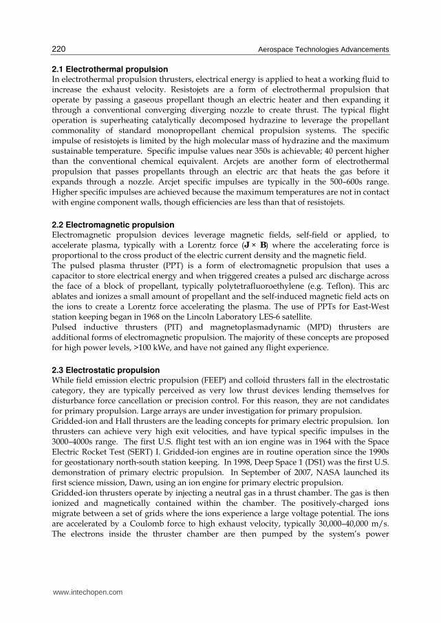
he ISPT project iown in figure 6,ovide a low-costissions. The HiVHEXT, but a highere anticipated de
ominal full poweficiency.
g. 6. HiVHAC lab
gnificant advancegh discharge voltd a very long-lifall thruster has idded-ion alternaccessfully comple
750 hours of opesign and developgineering model
sting starting in truster lifetime carougput in excess
Interplanetary
here is a misconways translates dcket equation.
n Technologies, Mis
e than 425kg of us throttle condit
achieved by a roughout. is also investing , is the first NASt electric propulsHAC thruster dor thrust-to-poweremands of theseer operation of 3
boratory model th
ements in the HiVtage for an incre
fe capability to alfewer parts and
atives. A laboratoeted its test demoeration at a dischpment of two enthruster should bthe fall of 2009. apability on the s of 600kg of prop
y application of
nception outside directly to higher
ssion Design, and A
xenon throughptions. The NEXT gridded ion thru
in the HiVHACSA electric propuion option optim
oes not provide ar ratio and lower smaller class s
3.6kW and a spe
hruster.
VHAC thruster ineased specific impllow for greater td low complexi
ory model HiVHAonstrating over 10harge voltage of ngineering modebe delivered and The engineeringorder of 30,000
pellant (Kamhaw
f electric propu
the low-thrust cperformance. Th
Application
put and has excwear test has deuster. Wear rat
C thruster (Manulsion thruster s
mized for Discoveas high a maximupower requirem
science missions.ecific impulse of
nclude a very largpulse over convetotal impulse witty with significa
AC thruster unde00kg of propellan700V. The ISPT
l HiVHAC thrusavailable to begi
g model thrusters hours of operai et al., 2009).
ulsion
community that his belief is found
eeded 23,000 hoemonstrated the ltes predict first
zella, 2007). HiVpecifically designery and New Froum specific impu
ments are well suit. The HiVHAC
2,800 seconds a
ge (12:1) throttle entional Hall thrth fewer thrusterant cost benefitsrwent wear testinnt throughput anT project procursters with Aerojein performance as are projected toation or having a
high specific imded from Tsiolko
225
ours of largest failure
VHAC, ned to ontiers ulse as ted for has a
at 55%
range, usters, rs. The s over ng and
nd over ed the et. The and life o have a total
mpulse ovsky’s
www.intechopen.com
Aerospace Technologies Advancements 226
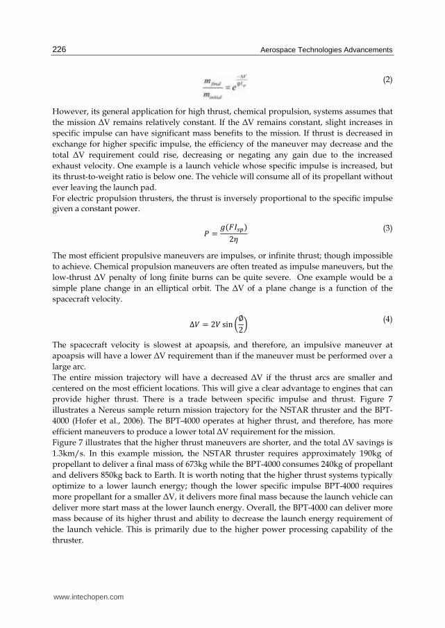
(2)
However, its general application for high thrust, chemical propulsion, systems assumes that
the mission ΔV remains relatively constant. If the ΔV remains constant, slight increases in
specific impulse can have significant mass benefits to the mission. If thrust is decreased in
exchange for higher specific impulse, the efficiency of the maneuver may decrease and the
total ΔV requirement could rise, decreasing or negating any gain due to the increased
exhaust velocity. One example is a launch vehicle whose specific impulse is increased, but
its thrust-to-weight ratio is below one. The vehicle will consume all of its propellant without
ever leaving the launch pad.
For electric propulsion thrusters, the thrust is inversely proportional to the specific impulse given a constant power.
鶏 噺 訣岫繋荊鎚椎岻2考 (3)
The most efficient propulsive maneuvers are impulses, or infinite thrust; though impossible
to achieve. Chemical propulsion maneuvers are often treated as impulse maneuvers, but the
low-thrust ΔV penalty of long finite burns can be quite severe. One example would be a
simple plane change in an elliptical orbit. The ΔV of a plane change is a function of the
spacecraft velocity.
∆撃 噺 2撃 sin 磐叶2卑 (4)
The spacecraft velocity is slowest at apoapsis, and therefore, an impulsive maneuver at
apoapsis will have a lower ΔV requirement than if the maneuver must be performed over a
large arc.
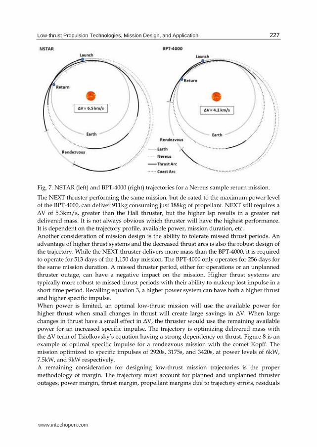
The entire mission trajectory will have a decreased ΔV if the thrust arcs are smaller and
centered on the most efficient locations. This will give a clear advantage to engines that can
provide higher thrust. There is a trade between specific impulse and thrust. Figure 7
illustrates a Nereus sample return mission trajectory for the NSTAR thruster and the BPT-
4000 (Hofer et al., 2006). The BPT-4000 operates at higher thrust, and therefore, has more
efficient maneuvers to produce a lower total ΔV requirement for the mission.
Figure 7 illustrates that the higher thrust maneuvers are shorter, and the total ΔV savings is
1.3km/s. In this example mission, the NSTAR thruster requires approximately 190kg of
propellant to deliver a final mass of 673kg while the BPT-4000 consumes 240kg of propellant
and delivers 850kg back to Earth. It is worth noting that the higher thrust systems typically
optimize to a lower launch energy; though the lower specific impulse BPT-4000 requires
more propellant for a smaller ΔV, it delivers more final mass because the launch vehicle can
deliver more start mass at the lower launch energy. Overall, the BPT-4000 can deliver more
mass because of its higher thrust and ability to decrease the launch energy requirement of
the launch vehicle. This is primarily due to the higher power processing capability of the
thruster.
www.intechopen.com
Low-thrust Propulsion Technologies, Mission Design, and Application 227
Fig. 7. NSTAR (left) and BPT-4000 (right) trajectories for a Nereus sample return mission.
The NEXT thruster performing the same mission, but de-rated to the maximum power level
of the BPT-4000, can deliver 911kg consuming just 188kg of propellant. NEXT still requires a
ΔV of 5.3km/s, greater than the Hall thruster, but the higher Isp results in a greater net
delivered mass. It is not always obvious which thruster will have the highest performance.
It is dependent on the trajectory profile, available power, mission duration, etc.
Another consideration of mission design is the ability to tolerate missed thrust periods. An
advantage of higher thrust systems and the decreased thrust arcs is also the robust design of
the trajectory. While the NEXT thruster delivers more mass than the BPT-4000, it is required
to operate for 513 days of the 1,150 day mission. The BPT-4000 only operates for 256 days for
the same mission duration. A missed thruster period, either for operations or an unplanned
thruster outage, can have a negative impact on the mission. Higher thrust systems are
typically more robust to missed thrust periods with their ability to makeup lost impulse in a
short time period. Recalling equation 3, a higher power system can have both a higher thrust
and higher specific impulse.
When power is limited, an optimal low-thrust mission will use the available power for
higher thrust when small changes in thrust will create large savings in ΔV. When large
changes in thrust have a small effect in ΔV, the thruster would use the remaining available
power for an increased specific impulse. The trajectory is optimizing delivered mass with
the ΔV term of Tsiolkovsky’s equation having a strong dependency on thrust. Figure 8 is an
example of optimal specific impulse for a rendezvous mission with the comet Kopff. The
mission optimized to specific impulses of 2920s, 3175s, and 3420s, at power levels of 6kW,
7.5kW, and 9kW respectively.
A remaining consideration for designing low-thrust mission trajectories is the proper
methodology of margin. The trajectory must account for planned and unplanned thruster
outages, power margin, thrust margin, propellant margins due to trajectory errors, residuals
www.intechopen.com

Aerospace Technologies Advancements 228
that cannot be expelled from the tank, or flow control accuracy, ΔV margins, etc. Though the
margins are interdependent, the electric propulsion system can offer advantages with an
ability to compensate for one area with additional margin in another (Oh et al., 2008).
In general, interplanetary missions with the greatest benefit of using electric propulsion are
missions that do not capture into large gravity wells, and have very large total ΔV mission
requirements. High ΔV missions include missions to multiple targets, large inclination
changes, and deep space rendezvous with trip time limitations. Trajectory analyses were
performed in Copernicus and MIDAS for chemical comparison and using SEPTOP,
SEPSPOT, and MALTO for the low thrust solutions.
Fig. 8. Optimal specific impulse comparison for a comet rendezvous mission.
4.1 Multiple targets Multi-target missions are a method to achieve considerably higher science return for a single
spacecraft. Multi-target missions can range from two targets in similar orbits, several targets
requiring large maneuvers, and to some extent, sample return missions.
The Dawn mission illustrates the mission enhancing capabilities of electric propulsion for
just such a mission. It is the first NASA science mission to use electric propulsion. For a
mission to be competitively selected and to justify new technology, the science return must
be remarkably high. The Dawn mission utilizes a single spacecraft that carries an instrument
suite to multiple targets, Ceres and Vesta. By traveling to multiple targets with a single
spacecraft there are savings in spacecraft development, instrument development, and
launch costs. The mission provides a unique opportunity to compare data from an identical
sets of instruments. The Dawn mission was determined to only be viable through the use of
electric propulsion. The use of chemical propulsion required significantly higher launch
mass and could only feasibly reach a single target. Figure 9 illustrates the Dawn EP multi-
rendezvous trajectory.
www.intechopen.com

Low
Fig
Fo
mi
ins
gre
sys
pe
nu
po
inc
pro
UsreqmithrsyssysilluNEHiinc
w-thrust Propulsion
g. 9. Trajectory of
r a Dawn-like m
ission advantages
sufficient to com
eater payload, bu
stem complexity
rforming the D
umerous advanta
ower requirement
cluding significan
ofile.
sing a thruster tquirements, reduissions can benefiruster can delivestem is expectedstem is expectedustrates performaEXT thruster caniVHAC thruster, creased performa
n Technologies, Mis
f the Dawn missio
mission, the use o
s over NSTAR. T
mplete the mission
ut can do so us
and spacecraft in
awn mission w
ages including g
ts are driven by t
nt operation at re
that can throttle ucing the overall it from higher threr greater paylo to have lower th
d to provide sigance and cost ben
n outperform the specifically desig
ance and reduced
ssion Design, and A
on to Ceres and V
of either the NEX
The throughput c
n. The use of th
ing a single thru
ntegration advant
with a single op
greater payload a
the need to opera
elatively high AU
to very low pospacecraft cost.
rust, lower specifad than the NShruster and pow
gnificant reductionefits of ISPT proj
NSTAR thrustergned for Discove system complex
Application
Vesta (Brophy et a
XT or HiVHAC t
capability of a sin
he NEXT thruste
uster. The use of
tages. The HiVHA
erating thruster,
and reduced cos
ate the thruster th
U. Figure 10 illust
ower can reduceBecause many s
fic impulse, thrusTAR thruster. F
wer processing unons in IPS costs ject technologies r with reduced sery Class missionity and cost (Oh,
al., 2008).
thruster has sign
ngle NSTAR thru
er can not only d
f a single thrust
AC thruster, capa
, is expected to
st. The Dawn m
hroughout the m
trates the Dawn
e the spacecraft small body rendesters, a low powe
Finally, a Hall thnit costs. The HiV
over SOA. Figuover SOA. Overaystem complexit
ns, has the potent2005).
229
nificant
uster is
deliver
ter has
able of
o have
mission
mission,
power
power ezvous er Hall hruster VHAC ure 11 all, the ty. The tial for
www.intechopen.com

23
Fig
Fig
ThDataropintincplafro
0
g. 10. Power profi
g. 11. Mass and co
he extreme examawn” class missirgets with a singl
pens up the trade terest targets are clination, eccentranning could alloom several second
ile for the Dawn m
ost comparison fo
mple of a multiplon is the conceple launch. The thspace of achievabnot necessarily cicity, period, etcow missions to vdary near-by targ
mission (Oh, 2007
or the Dawn miss
le target missionpt of traveling tohroughput potentble multi-rendezvo-located to allow. Sufficient throu
visit multiple higgets.
Aerospace Tec
7).
sion (Reference).
n would be a Suo and stopping atial of both NEXTvous options. Unw for short transfughput capabilit
gh interest targets
chnologies Advanc
uper-Dawn. A “Sat several high inT and HiVHAC gnfortunately, mosfers due to varianty and creative ms and gain inform
ements
Super-nterest greatly st high nces in
mission mation
www.intechopen.com

Low-thrust Propulsion Technologies, Mission Design, and Application 231
The targets for a hypothetical “Super-Dawn” mission were chosen from a list of high interest targets formulated by the scientific community. Based on preliminary analysis of throughput requirements and delivered mass, a single spacecraft, with only a 5-kW array, could be used to rendezvous with four high interest near-Earth targets shown in table 1. The final delivered mass is comparable to the Dawn spacecraft. The “Super-Dawn” mission illustrates the tremendous potential of electric propulsion for these types of missions. Studies have looked at using a single spacecraft for tours of near-Earth objects, main-belt asteroids, and even Jupiter Trojans. Sample return missions are multi-body missions because they need to return to Earth. Sample return missions are often considered high priority because of the higher fidelity science that can be performed terrestrially. Mars sample return was under investigation for many years, but the large costs of such a mission has deterred its implementation. Regolith from Phobos and Deimos are of high scientific value. The mission options offer significantly lower cost with minimal technology development required.
Segment Target Start Mass,
kg
Propellant
Required, kg
End Mass,
kg
1 Nereus 1650 309 1341
2 1993 BD3 1341 52 1289
3 Belenus 1289 44 1245
4 1996 FG3 1245 456 789
Table 1. Table of ΔV for a “Super-Dawn” type mission.
Two concepts for a Phobos and Deimos sample return mission were evaluated using solar electric propulsion: a single spacecraft to both moons or twin spacecraft capable of returning samples from either moon. The small bodies of Phobos and Deimos, with small gravity fields (especially Deimos), make electric propulsion rendezvous and sample return missions attractive. Electric propulsion systems can be used for the transfer to Mars, and then to spiral into an orbit around the moons. Chemical systems cannot easily leverage the Oberth effect for the sample return mission from Mars‘ moons because of the higher altitude orbit requirement. So while the mission can be completed, it comes at a large mass penalty. Figure 12 illustrates the benefits of using electric propulsion for a Phobos and Deimos sample return mission. Results show significant savings for using electric propulsion for Phobos and Deimos sample return missions. The baseline case uses a NEXT thruster with one operating thruster, and a spare system for redundancy (1+1). A Delta II class launch vehicle is capable of delivering enough mass for a sample return from both targets. For electric propulsion, the transfer between Phobos and Deimos has minimal mass implications. The mass and technology requirements could potentially fit within the Mars Scout cost cap. Using an Evolved Expendable Launch Vehicle (EELV), twin electric propulsion vehicles can be sent for a low-risk approach of collecting samples from Phobos and Deimos independently. However, the use of an EELV enables a chemical solution for a sample return mission. Going to a single moon chemically remains a significant challenge and results in a spacecraft that is greater than 70 percent propellant; a mass fraction more typical of a launch vehicle stage. Launching a single chemically propelled spacecraft to retrieve samples from both moons requires staging events adding risk and complexity.
www.intechopen.com

Aerospace Technologies Advancements 232
Fig. 12. Comparison of required launch mass for chemical and EP Mars’ moons missions.
The use of electric propulsion was studied for various comet surface sample return (CSSR)
missions. The results are highly dependant on the targets of interest. Electric propulsion
compares favorably with chemical alternatives resulting in either higher performance or
reduced trip times. Studies for Temple 1 (Woo et al., 2006) determined the SOA NSTAR
thruster to be inadequate due to its propellant throughput capability. The mission required
the use of a NEXT thruster. Studies for the comet Wirtanen (Witzberger, 2006) were
conducted and determined that the NSTAR could not deliver positive payload while both
the NEXT and HiVHAC thrusters can complete the mission with sufficient margin. The
largest benefit is that electric propulsion enables a wide range of targets that cannot be
reached using chemical propulsion systems.
In 2008, NASA GRC completed a mission design study for a multiple near-Earth asteroid
sample return mission (Oleson et al., 2009). The results indicated that it is feasible to use
electric propulsion to collect multiple samples from two distinct targets in very different
orbits. An Earth fly-by was performed after leaving the primary target and before arriving at
the second to releae the sample return capsule for a lower risk mission and mass savings to
the secondary target. This mission was not feasible using chemical propulsion. The
conceptual spacecraft for the multi-asteroid sample return mission is shown in figure 13.
4.2 Inclined targets Other missions enabled by electric propulsion are missions to highly inclined targets. There
are several Earth crossing targets that are thought to be old and inactive comets. These
asteroids typically have inclined orbits. The ∆V requirement for a plane change is a function
of the spacecraft velocity and angle of the plane change as shown in equation 1. With the
Earth’s heliocentric orbital speed near 30 km/s, a simple plane change of even 30 degrees
will require a ∆V of at least 15 km/s to perform a fly-by, following equation 4.
www.intechopen.com

Low
Fig
AnEainchiglow14 the
Fig
w-thrust Propulsion
g. 13. NEARER sp
n example missioarth-crossing bodclination of 64º. Bgh launch velocitwer velocity. Figukm/s. The Tsiol
e mission is comp
g. 14. Optimal che
n Technologies, Mis
pacecraft photo.
on to an inclined dy with a semi-mBecause of the incty so that the spaure 14 illustrates tlkovsky’s mass frpletely infeasible
emical trajectory
ssion Design, and A
target would be major axis of 1.2clination change, acecraft can perfothe chemical tranraction is only onwith any launch
to Tantalus.
Application
to the asteroid T29 AU, an eccenthe optimal chem
orm the plane chansfer which requin the order of onvehicle using che
Tantalus. Tantaluntricity of 0.3, a
mical transfer requange at high AU res a post-launch
ne percent dry memical propulsion
233
us is an and an uires a with a
h ∆V of ass, so n.
www.intechopen.com

Aerospace Technologies Advancements 234
The electric propulsion transfer to Tantalus is also a challenging mission. The low-thrust transfer is over 30 km/s over 4.5 years, but can still deliver over 800 kg of dry mass on a rendezvous mission using an Atlas V. The mission would require two NEXT thrusters, and would not be viable with the NSTAR or Hall thruster based propulsion system. Rather than going to high AU to perform the plane change, the low-thrust transfer gradually performs the plan change through several revolutions. Figure 15 illustrates the low-thrust transfer to Tantalus. Because of the advantages of electric propulsion, efficient use of propellant and low-thrust trajectory options, scientists can plan missions to high interest targets previously unattainable.
Fig. 15. Optimal low-thrust trajectory to Tantalus.
4.3 Radioisotope electric propulsion Another area of interest pushing the limits of propulsion technology is the use of a radioisotope power source with an electric propulsion thruster. This achieves high post launch ∆V on deep-space missions with limited solar power. Radioisotope electric propulsion systems (REPS) have significant potential for deep-space rendezvous that is not possible using conventional propulsion options. One example of mission that can benifit from REPS is a Centaur orbiter. The Centaurs are of significant scientific interest, and recommended by the Decadal Survey Primitive Bodies Panel as a New Frontiers mission for reconnaissance of the Trojans and Centaurs. The original recommendation was for a flyby of a Jupiter Trojan and Centaur. While a flyby mission can use imaging, imaging spectroscopy, and radio science for a glimpse at these objects, a REP mission provides an opportunity to orbit and potentially land on a Centaur. This greatly increases the science return. An exhaustive search of Centair obiter missions concluded that a wide range of Trojan flybys with Centaur Rendezvous missions are pracitical with near-term electric propulsion technology and a Stirling radioisotope generator (Dankanich & Oleson, 2008). With near-term technology, flyby missions may no longer be scientifically acceptable. Investigations are continuing using the enabling combination of electric propuslion and radioisotope power systems. On-going and recent studies include multi-Trojan landers, Kuiper-belt object rendezvous, Titan-to-Enceldaus
www.intechopen.com

Low
trasho
Fig
5.
ThsataltmobetcomA usetrepotrecomSevstato comapsigexptimKepoin
w-thrust Propulsion
ansfer, and Neptown in figure 16.
g. 16. Centaur orb
Near-Earth ap
here are currentlytellites have multitude, two from oon. The vast majtween low-Earthmmercial satelliteconjunction of de of electric prop
ends of satellite power technology, ends of both inmmunication sateveral studies we
arting at LEO. A leverage the lau
mmercial launchogee altitudes of
gnificantly reduceposure to the ra
mes and ∆V reqennedy Space Cenower-to-mass rati
figures 18 and
n Technologies, Mis
tune Orbiters. A
biter spacecraft de
plication of ele
y over 200 satellitiple thrusters. ONASA, one fromjority of mission h orbit (LEO) aes with GEO oper
developments greulsion for Earth-opower-to-mass raand the broad u
ncreasing power-ellites are shown ere performed tostrong deterrent unch vehicle to
h vehicles is to a f 185 km and 35e the orbit trans
adiation environmquirements fromnter (KSC)) wereos (Dankanich &19 respectively.
ssion Design, and A
A conceptual spa
esign.
ectric propulsi
ites using electricOnly four spacecrm JAXA to a near
pull of electric prand geosynchrorational orbits. eatly increased thorbit transportatiatios, required sp
use of electric pro-to-mass ratios in figure 17 (Bye
o evaluate the uis the very long an eccentric or
geosynchronous5,786 km respectfer time while a
ment within the m equatorial laune evaluated and c& Woodcock, 2006. Above 3 W/kg
Application
acecraft design o
on
c propulsion andraft flew beyondr-Earth object, anropulsion is for ap
onous Earth orb
he practicality anion. Key among tpacecraft mass, aopulsion systemsand spacecraft
ers & Dankanich, use of electric ptransfer times. O
rbit. The primary transfer orbit (Gtively. Launching
also reducing riskVan Allen belts
nch sites (Baikoncharacterized as a6). Results for KSg, the accelerati
of a Centuar orb
d the majority ofd geosynchronound one from ESA pplication in the
bit (GEO,) speci
nd expectations fthese advancemenadvancements ins. An illustration
mass for comm2008).
propulsion for trOne near-term opy design capabiGTO) with perigeg directly to GTOk of orbital debr. Analyses for trnur, Kourou, ana function of spaSC launches are son is high enou
235
biter is
f those s orbit to the
region ifically
for the nts are
n space of the
mercial
ransfer ption is lity of ee and O will
ris and ransfer nd the cecraft shown ugh to
www.intechopen.com

Aerospace Technologies Advancements 236
minimize gravity losses of the transfer. The low-thrust ∆Vs are approximately 800 m/s more than a chemical GEO insertion.
Fig. 17. Trends of commercial satellite beginning-of-life (BOL) P/M ratio and average mass.
Fig. 18. GTO-to-GEO transfer times as a function of spacecraft specific power.
www.intechopen.com
Low-thrust Propulsion Technologies, Mission Design, and Application 237
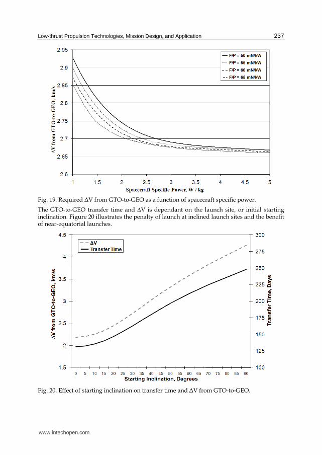
Fig. 19. Required ΔV from GTO-to-GEO as a function of spacecraft specific power.
The GTO-to-GEO transfer time and ∆V is dependant on the launch site, or initial starting inclination. Figure 20 illustrates the penalty of launch at inclined launch sites and the benefit of near-equatorial launches.
Fig. 20. Effect of starting inclination on transfer time and ΔV from GTO-to-GEO.
www.intechopen.com

Aerospace Technologies Advancements 238
There were 32 commercial communication satellites launched in 2005 and 2006 as provided
by the Union of Concerned Scientists database. These specific satellites were evaluated for
potential to use an integrated electric propulsion system with a specific impulse of 1000
seconds, 1500 seconds, and 2100 seconds. Integrated electric propulsion systems assume the
use of 95% of the onboard solar array power of the spacecraft as launched.
Using electric propulsion for the GEO insertion has significant mass benefits. Typically this
is evaluated as a method to leverage the launch vehicle performance to deliver the greatest
possible mass. Another perspective is to evaluate the potential for existing launch vehicles to
meet the demands of the COMSAT market. Figure 21 illustrates that currently launch
vehicles with GTO drop mass capabilities in excess of 7,500kg are required for a complete
market capture. However, using electric propulsion, a launch vehicle with a drop mass
capability of 5,500kg can have complete market capture. A low cost launcher with a
capability to deliver 3,500kg to 5,500kg can create a paradigm shift in the commercial launch
market. This assumes the commercial entity is willing to endure the long transfer time,
ranging from 66–238 days, depending on the spacecraft power-to-mass ratio and EP thruster
selected.
Fig. 21. Capture fraction as a function of GTO drop mass for various propulsion options.
6. Conclusion
Electric propulsion technology is widely used today, and multiple thrusters exist for
primary electric propulsion application. NASA and the U.S. commercial market developed
several thrusters suitable for primary electric propulsion on full scale spacecraft. The
www.intechopen.com
Low-thrust Propulsion Technologies, Mission Design, and Application 239
technology drivers for new electric propulsion thrusters include: ability to use available
power (i.e. high maximum power with large throttle range), increased total throughput
capability, and lower cost systems and integration. The optimal specific impulse is limited
by thrust required to minimize propulsive inefficiencies and available power. Due to power
constraints, the optimal specific impulse is typically less than 5,000s and closer to 2,000s for
near-Earth application. Electric propulsion is an enabling technology for a large suite of
interplanetary missions. Several targets are infeasible with advanced chemical propulsion
technologies, while practical with today’s electric propulsion options. Electric propulsion is
well suited for missions with very high post-launch ∆Vs including multi-target missions,
sample return missions, deep-space rendezvous, and highly inclined targets. Electric
propulsion has tremendous capability to impact the commercial launch market by
leveraging on-board available power. Today’s commercial satellites have mass-to-power
ratios for practical GTO-to-GEO low-thrust transfer. As available power and performance
demand continues to rise, electric propulsion technologies will continue to supplant
chemical alternatives for a wide range of missions. The technology will continue to focus on
developing lower cost propulsion systems with higher power and longer lifetime
capabilities.
7. References
Brophy, J. R. (2007). Propellant Throughput Capability of the Dawn ion Thrusters, IEPC-
2007-279, 30th International Electric Propulsion Conference, Florence, Italy,
September 2007.
Brophy, J., Rayman, M. D., & Pavri, B. (2008). Dawn: An Ion-propellanted Jounrey to the
Beginning of the Solar System, IEEE Aerospace Conference, Big Sky, MT, March
2008.
Byers, D., & Dankanich, J. W. (2008). Geosynchronous-Earth-Orbit Communication Satellite
Deliveries with Integrated Electric Propulsion. Journal of Power and Propulsion, Vol.
24, No. 6, November–December 2008, pp 1369–1375.
Dankanich, J. W. & Oleson, S. R. (2008). Radioisotope Electric Propulsion (REP) Centaur
Orbiter Mission Design, 44th AIAA/ASME/SAE/ASEE Joint Propulsion
Conference, Hartford, CT, July 2008.
Dankanich, J. W., & Woodcock, G. R. (2007). Electric Propulsion Performance from GEO-
Transfer to Geosynchronous Orbits, International Electric Propulsion Conference,
Florence, Italy, September 2007.
Kamhawi, H., Manzella, D., Pinero, L., & Mathers, A. (2009). Overview of the High Voltage
Hall Accelerator Project, AIAA 2009-5282, 45th AIAA/ASME/SAE/ASEE Joint
Propulsion Conference, Denver, CO, August 2009.
Manzella, D. (2007). Low Cost Electric Propulsion Thruster for Deep Space Robotic
Missions, 2007 NASA Science Technology Conference, University of Maryland,
MD, June 2007.
Oh, D. (2007). Evaluation of Solar Electric Propulsion Technologies for Discovery-Class
Missions. Journal of Spacecraft and Rockets, Vol. 44, No. 2., March-April 2007, pp 399–
411.
www.intechopen.com
Aerospace Technologies Advancements 240
Oh, D., Witzberger, K., & Cupples, M. 2004). Deep Space Mission Applications for NEXT:
NASA’s Evolutionary Xenon Thruster, AIAA-2004-3806, 40th
AIAA/ASME/SAE/ASEE Joint Propulsion Conference, Fort Laudersale, FL, July
2004.
Oleson, S. et al. (2009) Near-Earth Asteroid Sample Return Mission, 31st International
Electric Propulsion Conference, Ann Arbor, MI, September 2009 (to be publsihed).
Patterson, M. & Benson, S. (2007). NEXT Ion Propulsion System Development Status and
Performance, AIAA-2007-5199, 43rd AIAA/ASME/SAE/ASEE Joint Propulsion
Conference, Cincinatti, OH, July 2007.
Welander, B., Carpenter, C., de Grys, K., Hofer, R. R., Randolph, T. M., & Manzella, D. H.
(2006). Life and Operating Range Extension of the BPT-4000 Qualification Model
Hall Thruster, AIAA 2006-5263, 42nd AIAA/ASME/SAE/ASEE Joint Propulsion
Conference, Sacramento, CA, July 2006.
Wilson, F., & Smith, B. (2006). Hall Thruster System Qualification Provides Major Satellite
Benefits, IAC-06-C4.4.09, 57th International Astronautical Congress, Valencia,
Spain, October 2006.
Witzberger, K. E. (2006). Solar Electric Propulsion for Primitive Body Science Missions,
NASA TM 2006-214236, March 2006.
Woo, B., Coverstone, V. L., & Cupples, M. (2006). Application of Solar Electric Propulsion to
a Comet Surface Sample Return Missions. Journal of Spacecraft and Rockets, Vol. 43,
No. 6, November–December 2006, pp 1225–1230.
www.intechopen.com

Aerospace Technologies AdvancementsEdited by Thawar T. Arif
ISBN 978-953-7619-96-1Hard cover, 492 pagesPublisher InTechPublished online 01, January, 2010Published in print edition January, 2010
InTech EuropeUniversity Campus STeP Ri Slavka Krautzeka 83/A 51000 Rijeka, Croatia Phone: +385 (51) 770 447 Fax: +385 (51) 686 166www.intechopen.com
InTech ChinaUnit 405, Office Block, Hotel Equatorial Shanghai No.65, Yan An Road (West), Shanghai, 200040, China
Phone: +86-21-62489820 Fax: +86-21-62489821
Space technology has become increasingly important after the great development and rapid progress ininformation and communication technology as well as the technology of space exploration. This book dealswith the latest and most prominent research in space technology. The first part of the book (first six chapters)deals with the algorithms and software used in information processing, communications and control ofspacecrafts. The second part (chapters 7 to 10) deals with the latest research on the space structures. Thethird part (chapters 11 to 14) deals with some of the latest applications in space. The fourth part (chapters 15and 16) deals with small satellite technologies. The fifth part (chapters 17 to 20) deals with some of the latestapplications in the field of aircrafts. The sixth part (chapters 21 to 25) outlines some recent research efforts indifferent subjects.
How to referenceIn order to correctly reference this scholarly work, feel free to copy and paste the following:
John W. Dankanich (2010). Low-thrust Propulsion Technologies, Mission Design, and Application, AerospaceTechnologies Advancements, Thawar T. Arif (Ed.), ISBN: 978-953-7619-96-1, InTech, Available from:http://www.intechopen.com/books/aerospace-technologies-advancements/low-thrust-propulsion-technologies-mission-design-and-application

© 2010 The Author(s). Licensee IntechOpen. This chapter is distributedunder the terms of the Creative Commons Attribution-NonCommercial-ShareAlike-3.0 License, which permits use, distribution and reproduction fornon-commercial purposes, provided the original is properly cited andderivative works building on this content are distributed under the samelicense.