Embed Size (px)
Citation preview

GSFC· 2015
Thermal Fluid Analysis for
Nuclear Thermal Propulsion
Radiation Shield
Carlos Gomez
Marshall Space Flight Center

NTR
• Nuclear Thermal Rockets (NTR) are capable of producing high
specific impulse by employing heat produced by a nuclear fission
reactor to heat and therefore accelerate hydrogen through a rocket
nozzle providing thrust.
Reactor Core
Super Heated Hydrogen
Cold Gas Hydrogen
Radiation
• Nuclear radiation ( Gamma rays and high energy Neutrons) is freely
sprayed in all directions.
• Astronauts are exposed to nuclear and cosmic radiation
• Some components in the spacecraft are sensitive to radiation
damage caused by radiation embrittlement, particularly electronic
control circuits.
• Some materials are subjected to a substantial thermal load as
radiation energy is converted to heat
Radiation Shields and Shadow
4TFAWS 2015 – August 3-7, 2015 – Silver Spring, MD
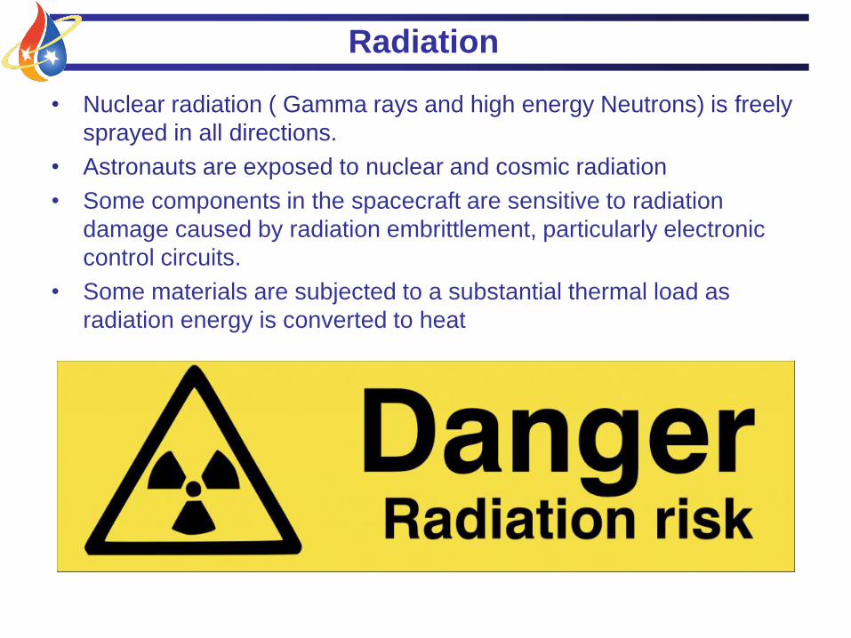
• Shadow shields are used specifically to protect the crew and spacecraft
components from radiation emitted by the NTR. A safe design would be to encase
the NTR in a shield, but that would reduce the ships payload since radiation
shields weigh tons.
• Engineering challenge: protect crew and reduce mass

Staging Radiation Shields
5TFAWS 2015 – August 3-7, 2015 – Silver Spring, MD
• Staging radiation shields help reduce weight but they have to be strategically
placed
• Internal shields receive the majority of the high energy radiation but require active
cooling due to the thermal loads.
• External shields provide the “shadow shielding” effect and are designed to be a
thick solid mass. These shields take advantage of radiative cooling and loses heat
by thermal radiation.
Internal
Shield
External
Disc Shield NASA-NERVA-diagram

Radiation Shield
Design Constraints and Materials
TFAWS 2015 – August 3-7, 2015 – Silver Spring, MD
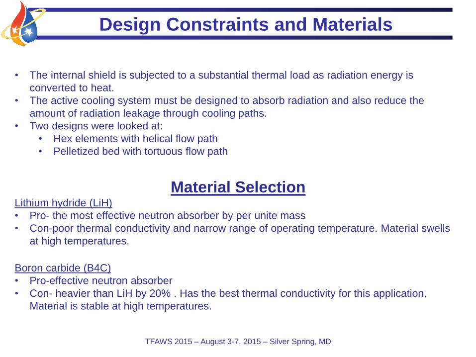
• The internal shield is subjected to a substantial thermal load as radiation energy is
converted to heat.
• The active cooling system must be designed to absorb radiation and also reduce the
amount of radiation leakage through cooling paths.
• Two designs were looked at:
• Hex elements with helical flow path
• Pelletized bed with tortuous flow path
Material SelectionLithium hydride (LiH)
• Pro- the most effective neutron absorber by per unite mass
• Con-poor thermal conductivity and narrow range of operating temperature. Material swells
at high temperatures.
Boron carbide (B4C)
• Pro-effective neutron absorber
• Con- heavier than LiH by 20% . Has the best thermal conductivity for this application.
Material is stable at high temperatures.

Internal Radiation Shield Concepts
TFAWS 2015 – August 3-7, 2015 – Silver Spring, MD
Hex elements stacked
• Cooling using flow channels
through each hexagon element creating
a helicoidal flow
Pelletized bed
• Randomly packed bed
• Tortuous flow distribution

COMSOL Assumptions for Pelletized Bed
TFAWS 2015 – August 3-7, 2015 – Silver Spring, MD
Model Parameters• Mass flow= 13.2 [kg/s]• Superficial Velocity= 5.4 [m/s]• Outlet Pressure= 3757 [kPa]• Inlet Temperature= 306.6 [K]• Shield Diameter= 1 [m]• Shield Length = 0.5 [m]• Void Fraction= 0.4• Mapped Heat Load• Allowable DeltaP= 1379[kPa]≈ 200 [psi]
Model Assumptions• Axisymmetric • Pellet Diameter= 2 [cm]• Density is based on ideal gas• Gas and pellet surface temperature
are the same

Heat Load Distribution
Note
• Heat loads were derived out
of a Monte Carlo radiation
transport code from Los Alamos
National Laboratory (LANL)

Temperature Distribution
TFAWS 2015 – August 3-7, 2015 – Silver Spring, MD
Pellet Surface Temp Assuming:• Mass flow= 13.2 [kg/s]• Superficial Velocity= 5.36 [m/s]• Pellet Diameter= 2 [cm]
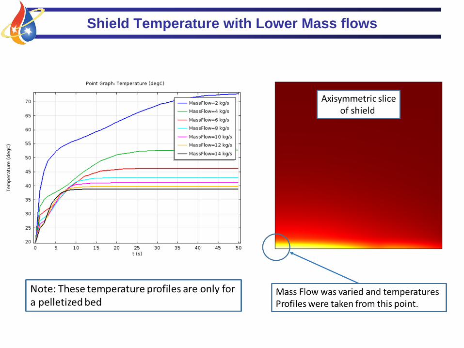
Shield Temperature with Lower Mass flows
Pelletized Bed Pressure Drop
TFAWS 2015 – August 3-7, 2015 – Silver Spring, MD
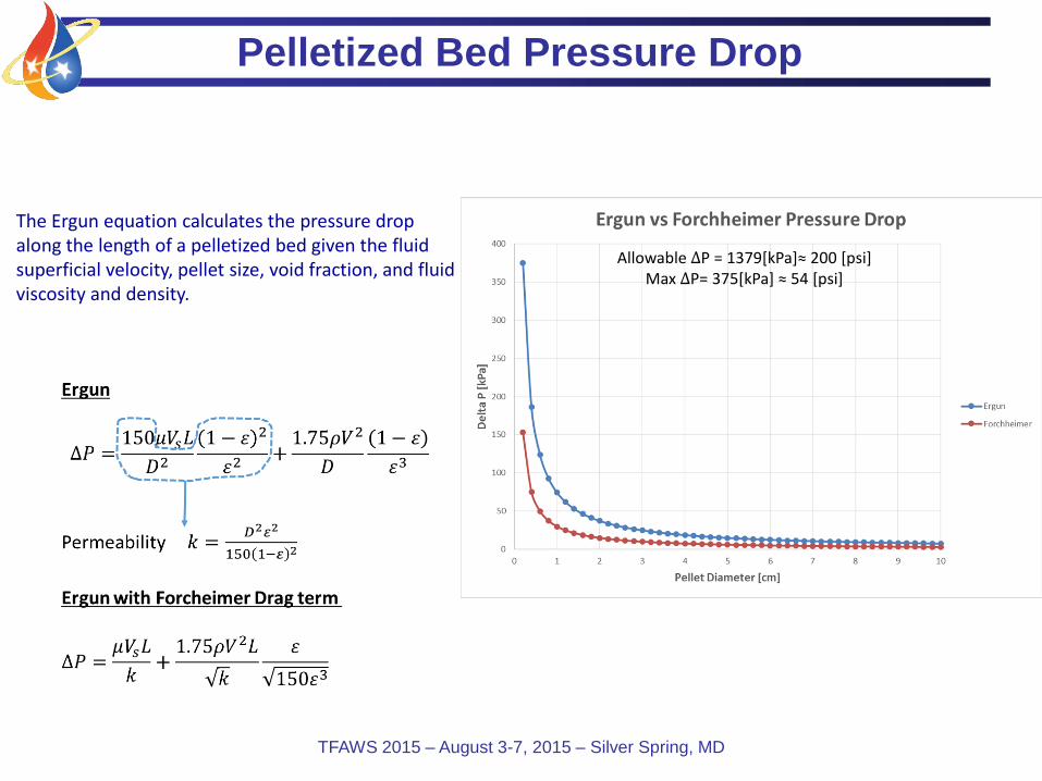
Allowable ∆P = 1379[kPa]≈ 200 [psi]Max ∆P= 375[kPa] ≈ 54 [psi]
The Ergun equation calculates the pressure dropalong the length of a pelletized bed given the fluid superficial velocity, pellet size, void fraction, and fluid viscosity and density.