Embed Size (px)
Citation preview
TS0066UK01
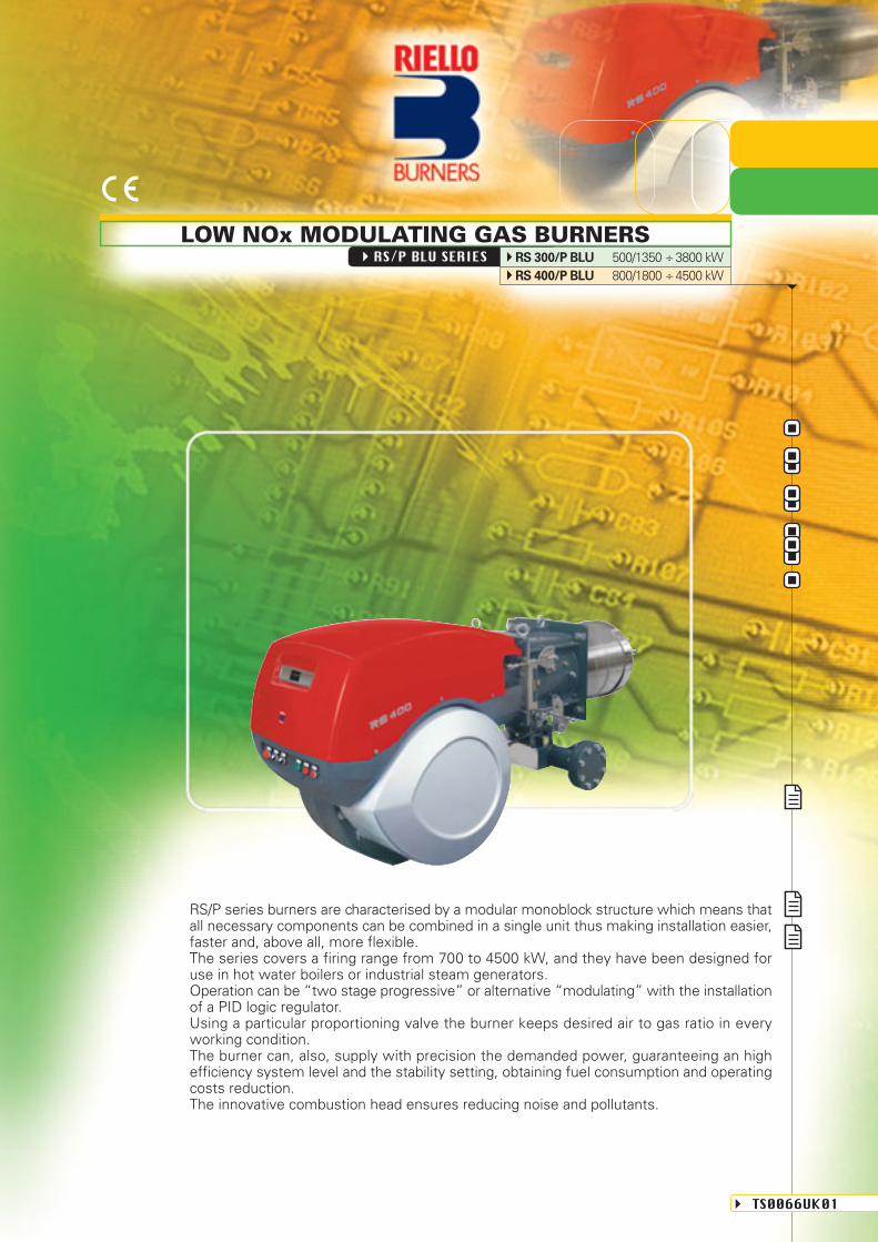
RS/P BLU SERIES RS 300/P BLU 500/1350 ÷ 3800 kWRS 400/P BLU 800/1800 ÷ 4500 kW
RS/P series burners are characterised by a modular monoblock structure which means thatall necessary components can be combined in a single unit thus making installation easier,faster and, above all, more flexible.The series covers a firing range from 700 to 4500 kW, and they have been designed foruse in hot water boilers or industrial steam generators.Operation can be “two stage progressive” or alternative “modulating” with the installationof a PID logic regulator.Using a particular proportioning valve the burner keeps desired air to gas ratio in everyworking condition.The burner can, also, supply with precision the demanded power, guaranteeing an highefficiency system level and the stability setting, obtaining fuel consumption and operatingcosts reduction.The innovative combustion head ensures reducing noise and pollutants.
LOW NOx MODULATING GAS BURNERS
TECHNICAL DATAA
pp
rova
lFu
el /
air
dat
aE
lect
rica
l d
ata
Em
issi
ons
type
s
kW
Mcal/h
°C min./max.
kWh/Nm3
kg/Nm3
Nm3/h
kWh/Nm3
kg/Nm3
Nm3/h
kWh/Nm3
kg/Nm3
Nm3/h
type
max °C
Ph/Hz/V
Ph/Hz/V
type
kW
kW
IP
kW
A
A
IP
type
V1 - V2
I1 - I2
dB (A)
W
mg/kWh
mg/kWh
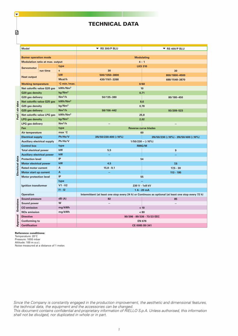
Model
Burner operation mode
Modulation ratio at max. output
Servomotorrun time
Heat output
Working temperature
Net calorific value G20 gas
G20 gas density
G20 gas delivery
Net calorific value G25 gas
G25 gas density
G25 gas delivery
Net calorific value LPG gas
LPG gas density
LPG gas delivery
Fan
Air temperature
Electrical supply
Auxiliary electrical supply
Control box
Total electrical power
Auxiliary electrical power
Protection level
Motor electrical power
Rated motor current
Motor start up current
Motor protection level
Ignition transformer
Operation
Sound pressure
Sound power
CO emission
NOx emission
Directive
Conforming to
Certification
Modulating
4 ÷ 1
LKS 310
0/60
10
0,71
8,6
0,78
25,8
2,02
Reverse curve blades
60
1/50/230 ~ (±10%)
RMG/M
54
55
--
230 V - 1x8 kV
1 A - 20 mA
Intermittent (at least one stop every 24 h) or Continuos as optional (at least one stop every 72 h)
< 10
< 80
90/396 - 89/336 - 73/23 EEC
EN 676
CE 0085 B0 341
RS 300/P BLU
30
500/1350÷3800
430/1161÷3268
50/135÷380
58/156÷442
--
3N/50/230-400 (±10%)
5,5
--
4,5
15,8 - 9,1
--
82
--
RS 400/P BLU
30
800/1800÷4500
688/1548÷3870
80/180÷450
93/209÷523
--
3N/50/230 (±10%) - 3N/50/400 (±10%)
9
--
7,5
17,5 - 30
113 - 195
85
--
Reference conditions:Temperature: 20°CPressure: 1000 mbarAltitude: 100 m a.s.l.Noise measured at a distance of 1 meter.
Since the Company is constantly engaged in the production improvement, the aesthetic and dimensional features,the technical data, the equipment and the accessories can be changed.This document contains confidential and proprietary information of RIELLO S.p.A. Unless authorised, this informationshall not be divulged, nor duplicated in whole or in part.
2
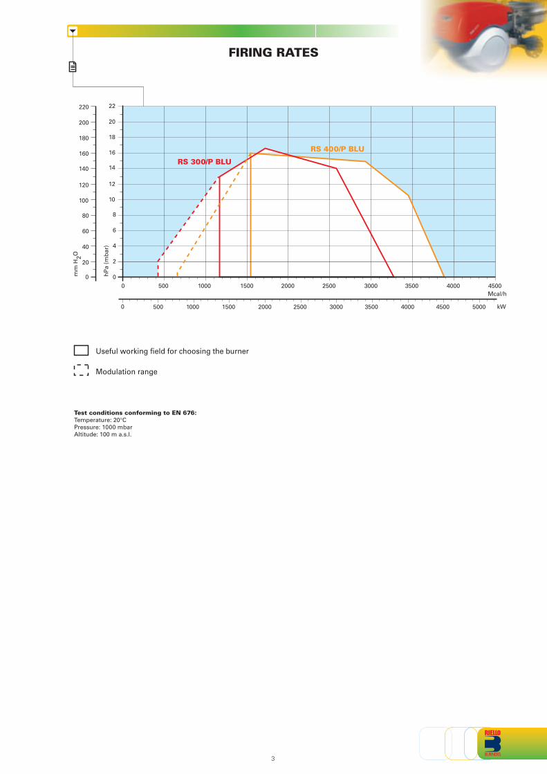
FIRING RATES
0
4
8
12
10
6
2
14
18
16
20
22
00
40
80
120
100
60
20
140
180
160
200
220
RS 300/P BLU
RS 400/P BLU
hP
a (m
bar
)
mm
H2O
3
Mcal/h15001000500 2000 2500 3000 3500 4000 4500
Test conditions conforming to EN 676:Temperature: 20°CPressure: 1000 mbarAltitude: 100 m a.s.l.
Useful working field for choosing the burner
Modulation range
kW500 10000 1500 2000 2500 3000 3500 4000 4500 5000
GAS TRAIN
FUEL SUPPLY
VGD gas train with seal control
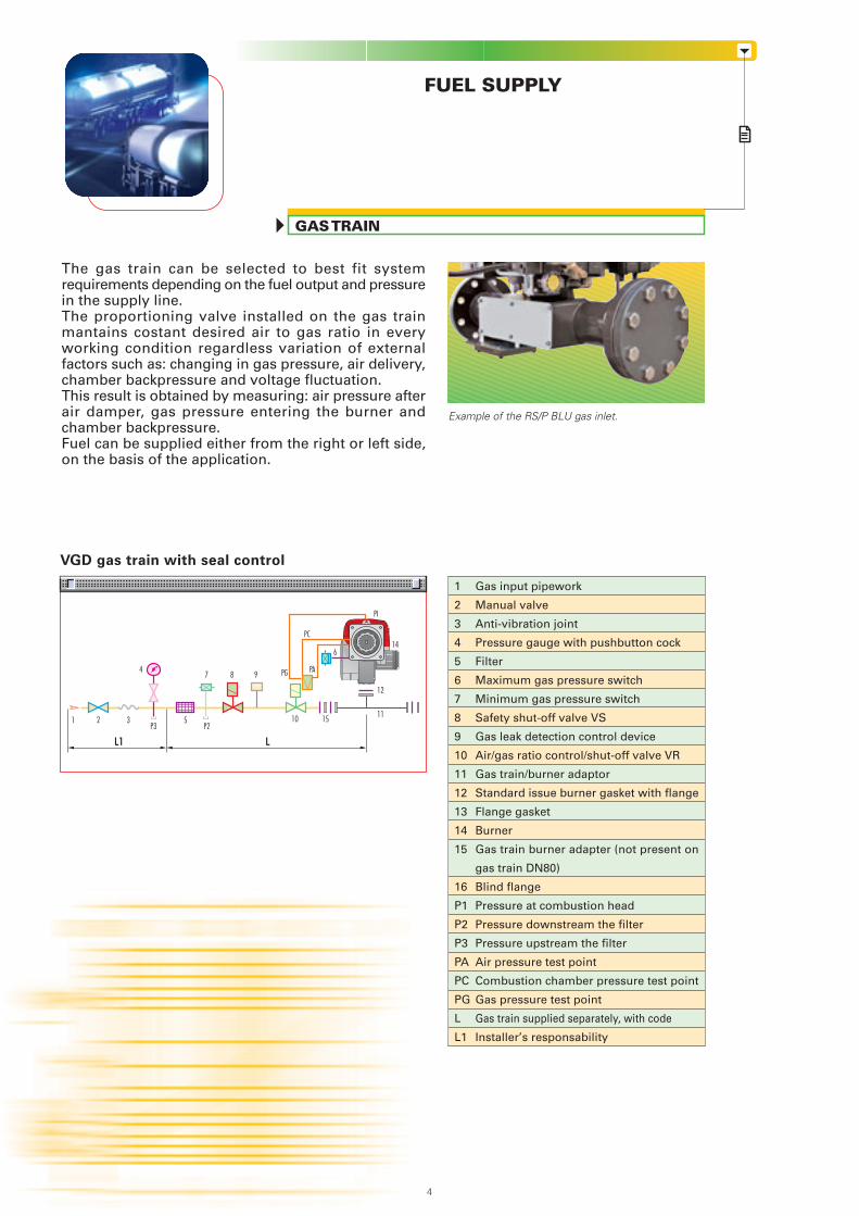
The gas train can be selected to best fit systemrequirements depending on the fuel output and pressurein the supply line.The proportioning valve installed on the gas trainmantains costant desired air to gas ratio in everyworking condition regardless variation of externalfactors such as: changing in gas pressure, air delivery,chamber backpressure and voltage fluctuation.This result is obtained by measuring: air pressure afterair damper, gas pressure entering the burner andchamber backpressure.Fuel can be supplied either from the right or left side,on the basis of the application.
Gas input pipework
Manual valve
Anti-vibration joint
Pressure gauge with pushbutton cock
Filter
Maximum gas pressure switch
Minimum gas pressure switch
Safety shut-off valve VS
Gas leak detection control device
Air/gas ratio control/shut-off valve VR
Gas train/burner adaptor
Standard issue burner gasket with flange
Flange gasket
Burner
Gas train burner adapter (not present on
gas train DN80)
Blind flange
Pressure at combustion head
Pressure downstream the filter
Pressure upstream the filter
Air pressure test point
Combustion chamber pressure test point
Gas pressure test point
Gas train supplied separately, with code
Installer’s responsability
1
2
3
4
5
6
7
8
9
10
11
12
13
14
15
16
P1
P2
P3
PA
PC
PG
L
L1
Example of the RS/P BLU gas inlet.
4
LL1
12
P3
PI
21P2
7 9
3
84
6
10 15
PG
PC
PA
14
511
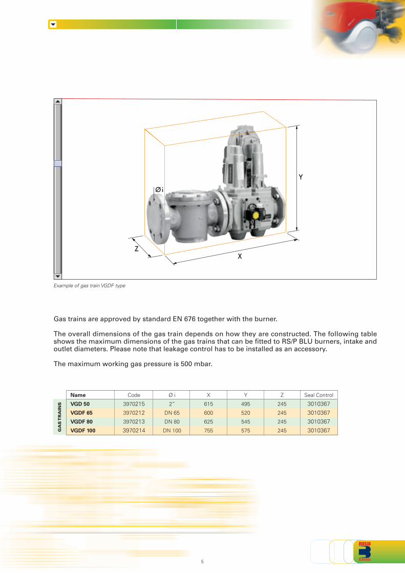
Example of gas train VGDF type
GA
S T
RA
INS
Name
VGD 50
VGDF 65
VGDF 80
VGDF 100
Code
3970215
3970212
3970213
3970214
Ø i
2”
DN 65
DN 80
DN 100
X
615
600
625
755
Y
495
520
545
575
Z
245
245
245
245
Seal Control
3010367
3010367
3010367
3010367
Gas trains are approved by standard EN 676 together with the burner.
The overall dimensions of the gas train depends on how they are constructed. The following tableshows the maximum dimensions of the gas trains that can be fitted to RS/P BLU burners, intake andoutlet diameters. Please note that leakage control has to be installed as an accessory.
The maximum working gas pressure is 500 mbar.
5
Y
ZX
Øi
RS 300/P BLU
RS 400/P BLU
PRESSURE DROP DIAGRAM
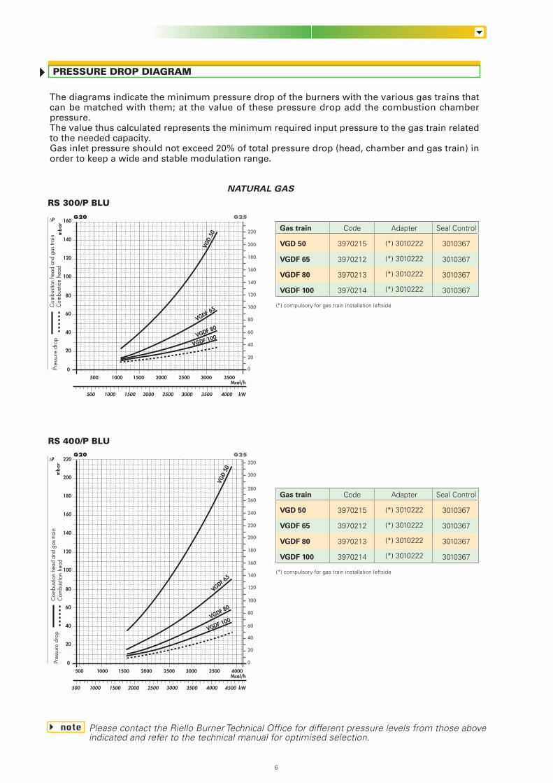
The diagrams indicate the minimum pressure drop of the burners with the various gas trains thatcan be matched with them; at the value of these pressure drop add the combustion chamberpressure.The value thus calculated represents the minimum required input pressure to the gas train relatedto the needed capacity.Gas inlet pressure should not exceed 20% of total pressure drop (head, chamber and gas train) inorder to keep a wide and stable modulation range.
NATURAL GAS
note Please contact the Riello Burner Technical Office for different pressure levels from those aboveindicated and refer to the technical manual for optimised selection.
(*) compulsory for gas train installation leftside
Gas train
VGD 50
VGDF 65
VGDF 80
VGDF 100
Code
3970215
3970212
3970213
3970214
Adapter
(*) 3010222
(*) 3010222
(*) 3010222
(*) 3010222
Seal Control
3010367
3010367
3010367
3010367
(*) compulsory for gas train installation leftside
Gas train
VGD 50
VGDF 65
VGDF 80
VGDF 100
Code
3970215
3970212
3970213
3970214
Adapter
(*) 3010222
(*) 3010222
(*) 3010222
(*) 3010222
Seal Control
3010367
3010367
3010367
3010367
Mcal/h
20
40
0
mb
ar
G25G20
0
kW
60
80
100
120
140
160
180
Com
busti
on h
ead
and
gas
train
Com
busti
on h
ead
Pres
sure
dro
p
20
40
60
80
100
120
140
160
180
200
220
240
280
2500 350030002000 4000 4500
3000 400035001500 25002000
500 1000 1500
500 1000
Mcal/h
20
40
0
mb
ar
G25G20
0
kW
60
80
100
120
140
160
Com
busti
on h
ead
and
gas
train
Com
busti
on h
ead
Pres
sure
dro
p
20
40
60
80
100
120
140
160
180
200
220
2500 350030002000 4000
3000 35001500 25002000
500 1000 1500
500 1000
VGD
50
VGDF 65
VGDF 80
VGDF 100
VGD
50
VGDF 65
VGDF 80
VGDF 100
ΔP
ΔP
200
220
260
300
320
6
7
0,1 0,2 0,3 0,4 0,5 0,6 0,7 0,8 1 2 3 4 5 106 20
50 60 10080 200 400 800 1000600
3
69
12152230
45 61 76 95 122 152 V1 2 3 4 5 6 7 8 10 20 30 40
1,4
1/2
3/4
1"
1" 1/2
6"
1" 1/4
4"
3"2" 1/22"
PRESSURE DROP (mbar)
PIPE DIAMETER
PIPE LENGTH (m)
= Gas output Nmc/h
f1 - G20
= 0,62 - G251,18 - G31{
fV
15,34
Figure A
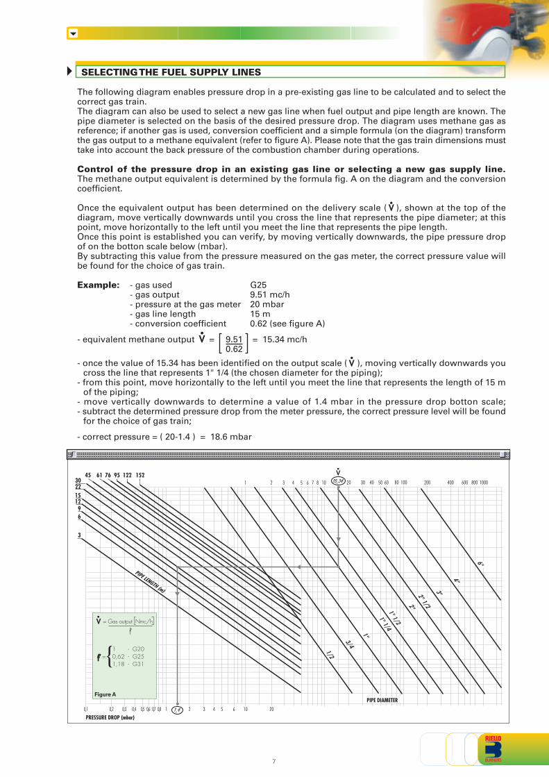
The following diagram enables pressure drop in a pre-existing gas line to be calculated and to select thecorrect gas train.The diagram can also be used to select a new gas line when fuel output and pipe length are known. Thepipe diameter is selected on the basis of the desired pressure drop. The diagram uses methane gas asreference; if another gas is used, conversion coefficient and a simple formula (on the diagram) transformthe gas output to a methane equivalent (refer to figure A). Please note that the gas train dimensions musttake into account the back pressure of the combustion chamber during operations.
Control of the pressure drop in an existing gas line or selecting a new gas supply line.The methane output equivalent is determined by the formula fig. A on the diagram and the conversioncoefficient.
Once the equivalent output has been determined on the delivery scale ( ), shown at the top of thediagram, move vertically downwards until you cross the line that represents the pipe diameter; at thispoint, move horizontally to the left until you meet the line that represents the pipe length.Once this point is established you can verify, by moving vertically downwards, the pipe pressure dropof on the botton scale below (mbar).By subtracting this value from the pressure measured on the gas meter, the correct pressure value willbe found for the choice of gas train.
Example: - gas used G25- gas output 9.51 mc/h- pressure at the gas meter 20 mbar- gas line length 15 m- conversion coefficient 0.62 (see figure A)
- equivalent methane output = 9.51 = 15.34 mc/h0.62
- once the value of 15.34 has been identified on the output scale ( ), moving vertically downwards youcross the line that represents 1" 1/4 (the chosen diameter for the piping);
- from this point, move horizontally to the left until you meet the line that represents the length of 15 mof the piping;
- move vertically downwards to determine a value of 1.4 mbar in the pressure drop botton scale;- subtract the determined pressure drop from the meter pressure, the correct pressure level will be found
for the choice of gas train;
- correct pressure = ( 20-1.4 ) = 18.6 mbar
V
V
V
SELECTING THE FUEL SUPPLY LINES
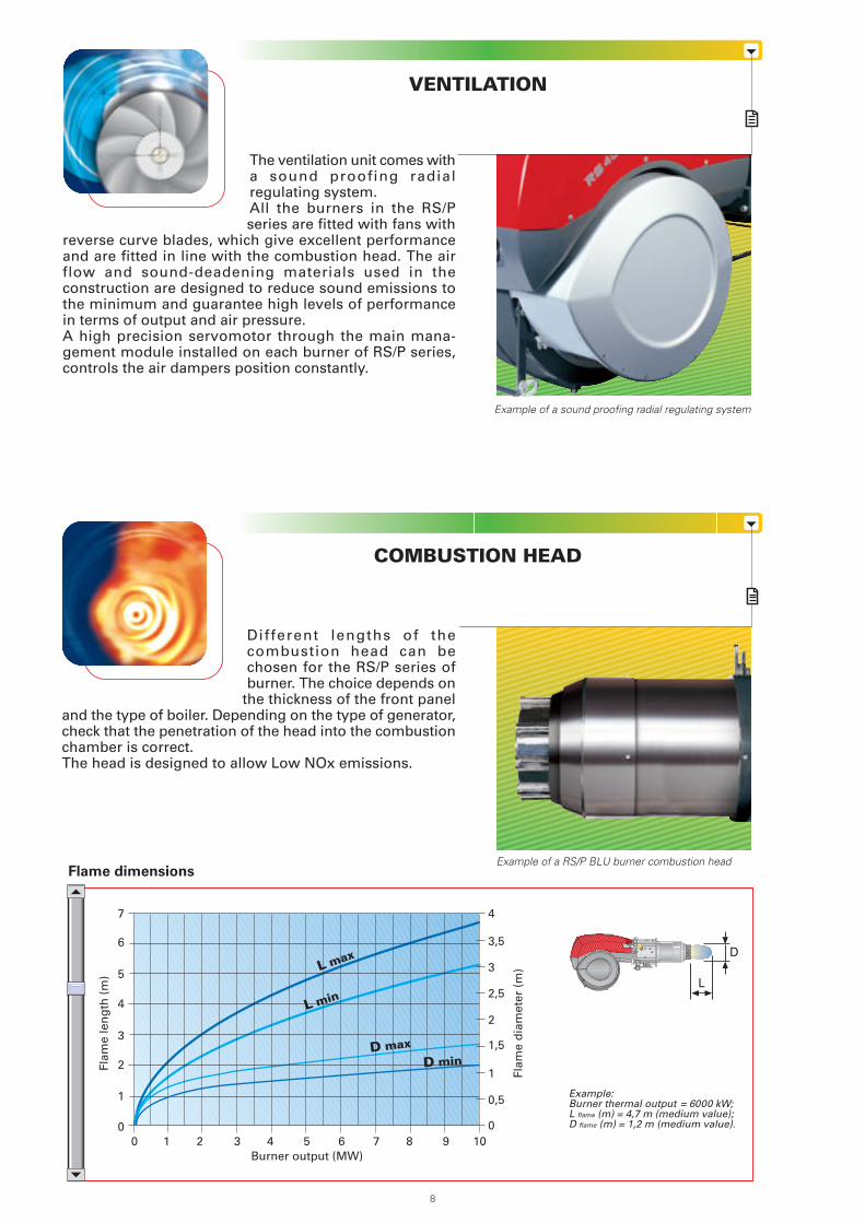
The ventilation unit comes witha sound proofing radialregulating system.All the burners in the RS/Pseries are fitted with fans with
reverse curve blades, which give excellent performanceand are fitted in line with the combustion head. The airflow and sound-deadening materials used in theconstruction are designed to reduce sound emissions tothe minimum and guarantee high levels of performancein terms of output and air pressure.A high precision servomotor through the main mana-gement module installed on each burner of RS/P series,controls the air dampers position constantly.
COMBUSTION HEAD
VENTILATION
Different lengths of thecombustion head can bechosen for the RS/P series ofburner. The choice depends on
the thickness of the front paneland the type of boiler. Depending on the type of generator,check that the penetration of the head into the combustionchamber is correct.The head is designed to allow Low NOx emissions.
Flame dimensions
Example:Burner thermal output = 6000 kW;L flame (m) = 4,7 m (medium value);D flame (m) = 1,2 m (medium value).
D
L
Burner output (MW)0 2
3
5
1
1 3
2
4
6
7
4 5 6 7 8 9 10
Flam
e le
ng
th (
m)
Flam
e d
iam
eter
(m
)
0
4
0
0,5
1
1,5
2
2,5
3
3,5
L max
L min
D max
D min
8
Example of a sound proofing radial regulating system
Example of a RS/P BLU burner combustion head
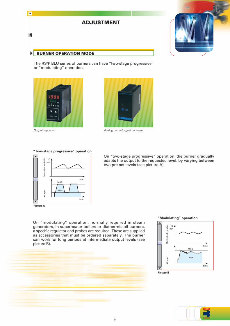
ADJUSTMENT
BURNER OPERATION MODE
On “modulating” operation, normally required in steamgenerators, in superheater boilers or diathermic oil burners,a specific regulator and probes are required. These are suppliedas accessories that must be ordered separately. The burnercan work for long periods at intermediate output levels (seepicture B).
On “two-stage progressive” operation, the burner graduallyadapts the output to the requested level, by varying betweentwo pre-set levels (see picture A).
Ou
tpu
tC
on
tro
lled
var
iab
le
Picture A
bar°C
MAX
MIN
time
time
The RS/P BLU series of burners can have “two-stage progressive”or “modulating” operation.
Output regulator
“Two-stage progressive” operation
Ou
tpu
t
Picture B
Co
ntr
olle
d v
aria
ble
bar°C
MAX
MIN
time
time
“Modulating” operation
9
Analog control signal converter
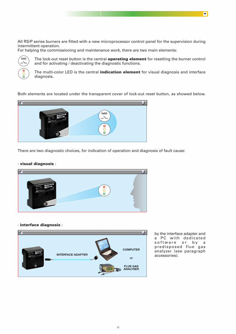
All RS/P series burners are fitted with a new microprocessor control panel for the supervision duringintermittent operation.For helping the commissioning and maintenance work, there are two main elements:
The lock-out reset button is the central operating element for resetting the burner controland for activating / deactivating the diagnostic functions.
The multi-color LED is the central indication element for visual diagnosis and interfacediagnosis.
Both elements are located under the transparent cover of lock-out reset button, as showed below.
There are two diagnostic choices, for indication of operation and diagnosis of fault cause:
- visual diagnosis :
- interface diagnosis :
by the interface adapter anda PC with dedicateds o f t w a r e o r b y apredisposed f lue gasanalyzer (see paragraphaccessories).
Switch
Switch
COMPUTER
or
FLUE GASANALYSER
INTERFACE ADAPTER
10
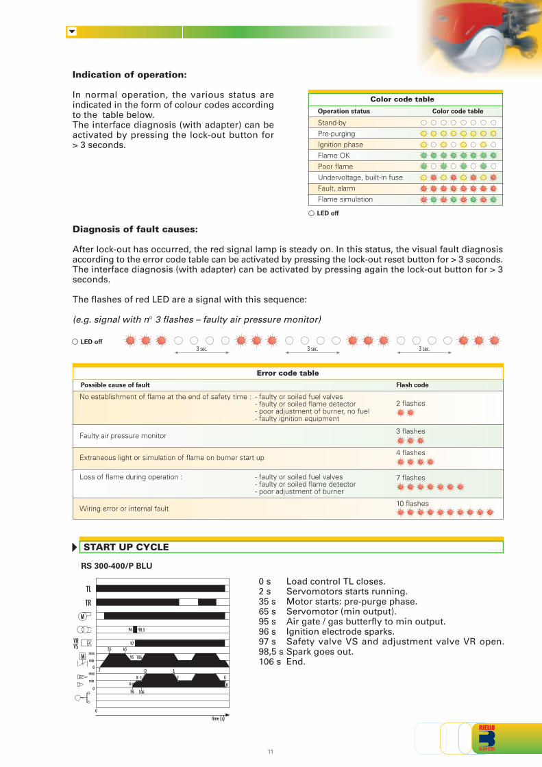
START UP CYCLE
RS 300-400/P BLU
Indication of operation:
In normal operation, the various status areindicated in the form of colour codes accordingto the table below.The interface diagnosis (with adapter) can beactivated by pressing the lock-out button for> 3 seconds.
Color code table
Operation status
Stand-byPre-purgingIgnition phaseFlame OKPoor flameUndervoltage, built-in fuseFault, alarmFlame simulation
Color code table
LED off
Diagnosis of fault causes:
After lock-out has occurred, the red signal lamp is steady on. In this status, the visual fault diagnosisaccording to the error code table can be activated by pressing the lock-out reset button for > 3 seconds.The interface diagnosis (with adapter) can be activated by pressing again the lock-out button for > 3seconds.
The flashes of red LED are a signal with this sequence:
(e.g. signal with n° 3 flashes – faulty air pressure monitor)
LED off3 sec. 3 sec. 3 sec.
time (s)
96 98,5
65
96 106
2
9735
95 106
AB C
D EF G
H
0 s Load control TL closes.2 s Servomotors starts running.35 s Motor starts: pre-purge phase.65 s Servomotor (min output).95 s Air gate / gas butterfly to min output.96 s Ignition electrode sparks.97 s Safety valve VS and adjustment valve VR open.98,5 s Spark goes out.106 s End.
M
0
0
max
min
TL
TR
VRVS
0
M
max
min
11
Error code table
Possible cause of fault Flash code
2 flashes
3 flashes
4 flashes
7 flashes
10 flashes
No establishment of flame at the end of safety time : - faulty or soiled fuel valves- faulty or soiled flame detector- poor adjustment of burner, no fuel- faulty ignition equipment
Faulty air pressure monitor
Extraneous light or simulation of flame on burner start up
Loss of flame during operation : - faulty or soiled fuel valves- faulty or soiled flame detector- poor adjustment of burner
Wiring error or internal fault
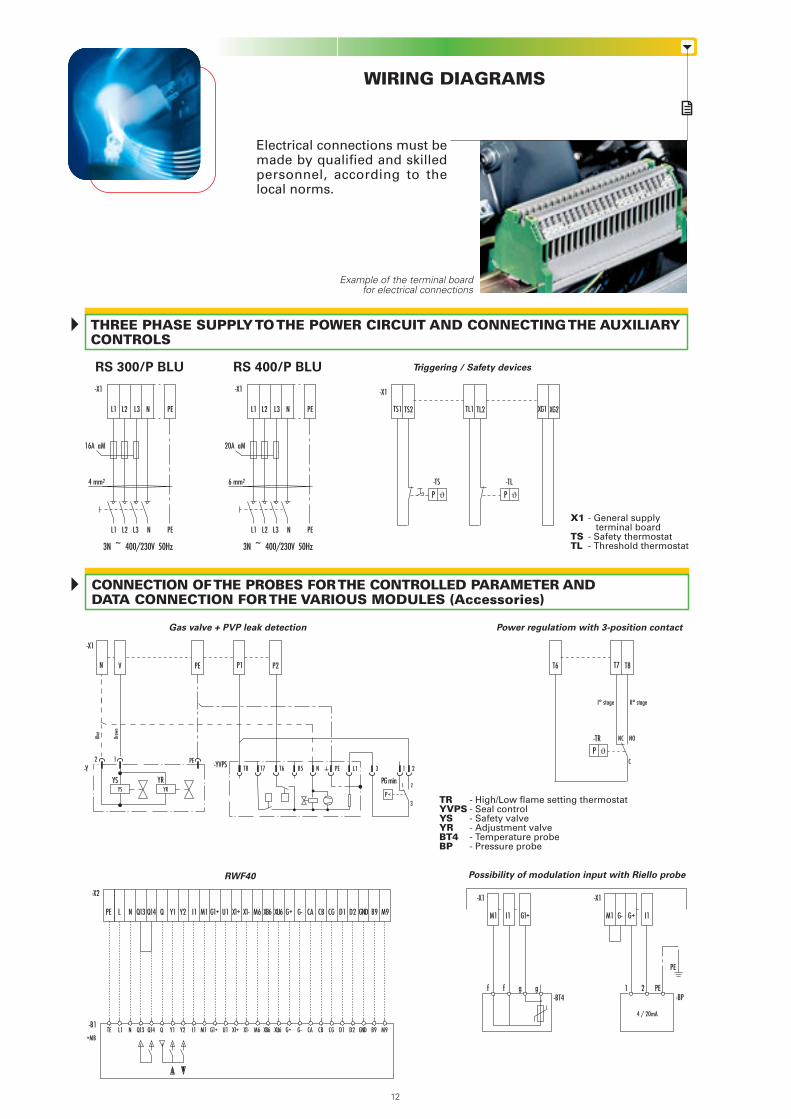
CONNECTION OF THE PROBES FOR THE CONTROLLED PARAMETER ANDDATA CONNECTION FOR THE VARIOUS MODULES (Accessories)
WIRING DIAGRAMS
Example of the terminal boardfor electrical connections
X1 - General supply terminal board
TS - Safety thermostatTL - Threshold thermostat
RS 400/P BLU Triggering / Safety devices
Gas valve + PVP leak detection Power regulatiom with 3-position contact
Possibility of modulation input with Riello probeRWF40
THREE PHASE SUPPLY TO THE POWER CIRCUIT AND CONNECTING THE AUXILIARYCONTROLS
RS 300/P BLU
Electrical connections must bemade by qualified and skilledpersonnel, according to thelocal norms.
L1 L2 L3 N PE
-X1
4 mm2
16A aM
L1 L2 L3 N PE
3N ~ 400/230V 50Hz
L1 L2 L3 N PE
-X1
6 mm2
20A aM
L1 L2 L3 N PE
3N ~ 400/230V 50Hz
I1M1 G1+ G+G- I1M1
1 2f f g g
4 / 20mA
-X1
-TS -TL
TS1 TS2 TL1 TL2 XG1 XG2
P ϑ P ϑ
-TR NC
T6 T7 T8
NO
I° stage II° stage
CP ϑ
12
TRYVPSYSYRBT4BP
- High/Low flame setting thermostat- Seal control- Safety valve- Adjustment valve- Temperature probe- Pressure probe
P
1 PE2
YS YR
PE-YVPS
YS YR
-X1
-Y NT8 T6T7 L1
PG minB5
N V PE P1 P2
2
3
13
21
Blue
Brow
n
-X1
PE
PE-BT4 -BP
-X1
Q13 Q14 Q I1 M1 G1+ U1 X1+ X1- M6 XB6 XU6 G+ G- CA CB CG D1 D2 GND B9 M9
Q13 Q14 Q I1 M1 G1+ U1 X1+ X1- M6 XB6 XU6 G+ G- CA CB CG D1 D2 GND B9 M9
-X2
-B1
+MB
NLPE Y1 Y2
NL1TE Y1 Y2
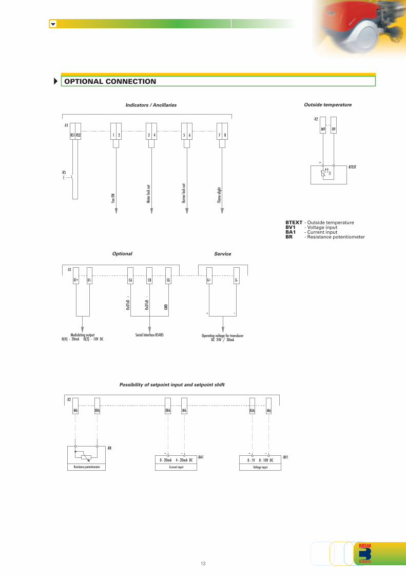
OPTIONAL CONNECTION
13
BTEXTBV1BA1BR
- Outside temperature- Voltage input- Current input- Resistance potentiometer
Indicators / Ancillaries
RS2RS1 32 41
Fan O
N
76 85
Motor
lock
out
Burn
er loc
k out
Flame
aligh
t
-X1
-RS
Outside temperature
B9M9
-X2
-BTEXT
Optional Service
X1-X1+
RxDT
xD
RxDT
xD
GND
CA CB CG G+ G-
Modulating output0(4) - 20mA 0(2) - 10V DC
Serial Interface RS485 Operating voltage for transducerDC 24V / 30mA
-X1
Possibility of setpoint input and setpoint shift
XB6M6
0 - 20mA 4 - 20mA DCResistance potentiometer
XB6 M6
Current input
0 - 1V 0 - 10V DC
XU6 M6
Voltage input
-X2
-BR
-BA1 -BV1

EMISSIONS
The noise emissionshave been measured atthe maximum output.
mg
/kW
h
0
25
50
75
100
RS 300/P BLU RS 400/P BLU
NO2 EMISSIONS
NOISE EMISSIONS
dB
(A)
0
20
40
60
80
100
RS 300/P BLU RS 400/P BLU
The RS/P BLU seriesr e d u c e s p o l l u t i n gemiss ions wi th i tsexclusive design whicho p t i m i s e s a i r / f u e lmixture.T h e g a s i n t h ecombustion head isdistr ibuted throughopenings which areperpendicular to the airflow; part of the fuel isinjected directly into thecentre of the flame.This results in low flametemperature combustion to prevent the formation of NO. Gradual and progressive combustionthroughout the flame prevents areas of high oxidation inside the flame. Emissions are further reducedby the re-circulation of combustion gases due to the high velocity of air leaving the combustion head.Pollution levels are below even the most severe standards requirement.
14
X
Z
Y
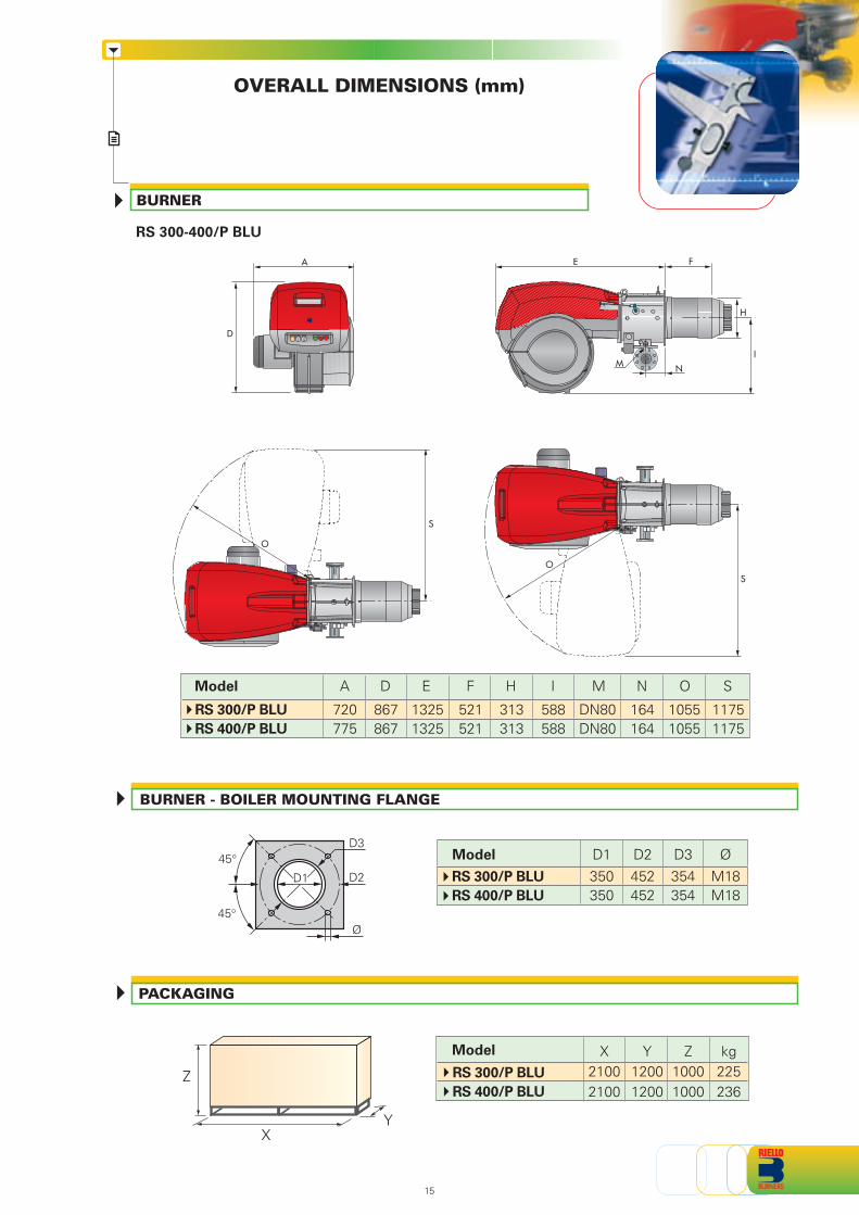
OVERALL DIMENSIONS (mm)
PACKAGING
BURNER - BOILER MOUNTING FLANGE
RS 300-400/P BLU
BURNER
ØD2350350
M18M18
452452
D1 D3354354
Model X21002100
Y12001200
kg225236
Z10001000
Model
RS 300/P BLU
RS 400/P BLU
RS 300/P BLU
RS 400/P BLU
Ø
D2
45°
45°
D3
A
D
E
I
F
M
H
N
S
O
O
S
15
A
720775
O
10551055
S
11751175
D
867867
588588
IH
313313
N
164164
F
521521
E
13251325
Model
RS 300/P BLU
RS 400/P BLU
M
DN80DN80
D1
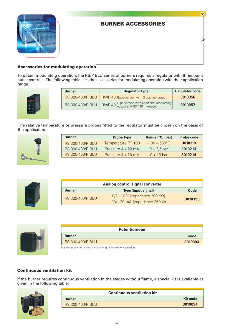
BURNER ACCESSORIES
The relative temperature or pressure probes fitted to the regulator must be chosen on the basis ofthe application.
Accessories for modulating operation
To obtain modulating operation, the RS/P BLU series of burners requires a regulator with three pointoutlet controls. The following table lists the accessories for modulating operation with their applicationrange.
Continuous ventilation kit
If the burner requires continuous ventilation in the stages without flame, a special kit is available asgiven in the following table:
Burner Kit code
Continuous ventilation kit
RS 300-400/P BLU 3010094
RS 300-400/P BLU
RS 300-400/P BLU
RWF 40
Regulator code
3010356
3010357
Burner
Probe type
Temperature PT 100Pressure 4 ÷ 20 mAPressure 4 ÷ 20 mA
RS 300-400/P BLURS 300-400/P BLURS 300-400/P BLU
Burner
Regulator type
RWF 40
Basic version with 3 position output
High version with additional modulatingoutput and RS 485 Interface
16
Range (°C) (bar)
-100 ÷ 500°C0 ÷ 2,5 bar0 ÷ 16 bar
Probe code
3010110
3010213
3010214
Analog control signal converter
Burner
RS 300-400/P BLU
Code
3010390
Type (input signal)
0/2 - 10 V (impedance 200 KΩ)0/4 - 20 mA (impedance 250 Ω)
RS 300-400/P BLU
Burner Code
3010393
Potentiometer
It is necessary for analogic control signal converter operation.
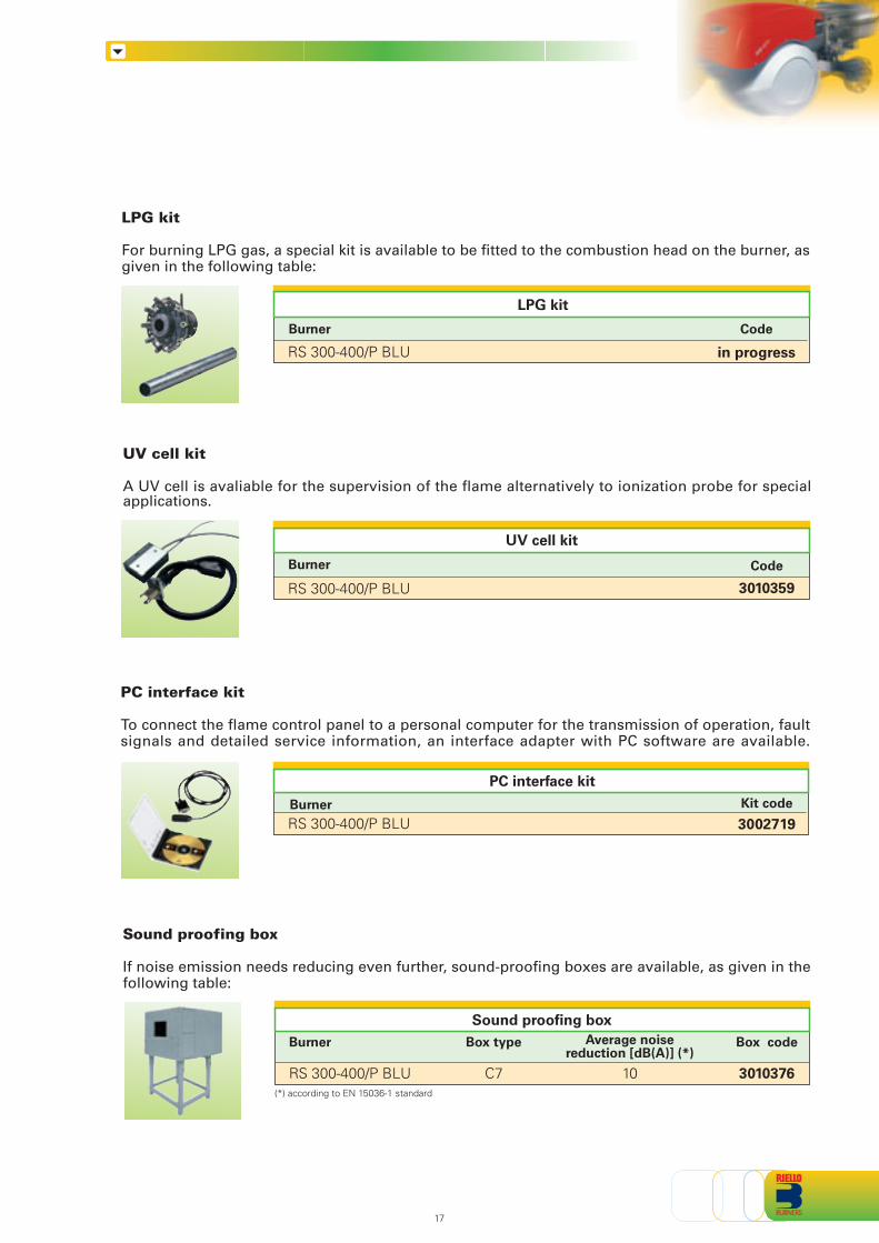
UV cell kit
A UV cell is avaliable for the supervision of the flame alternatively to ionization probe for specialapplications.
UV cell kit
Burner
LPG kit
Code
LPG kit
For burning LPG gas, a special kit is available to be fitted to the combustion head on the burner, asgiven in the following table:
in progress
PC interface kit
To connect the flame control panel to a personal computer for the transmission of operation, faultsignals and detailed service information, an interface adapter with PC software are available.
Burner Kit code
3002719
PC interface kit
Sound proofing box
If noise emission needs reducing even further, sound-proofing boxes are available, as given in thefollowing table:
RS 300-400/P BLU
Burner Box code
3010376C7
Box type
Sound proofing box
17
RS 300-400/P BLU
Code
3010359
Burner
RS 300-400/P BLU
RS 300-400/P BLU
(*) according to EN 15036-1 standard
10
Average noisereduction [dB(A)] (*)
GAS TRAIN ACCESSORIES
RS 300-400/P BLU
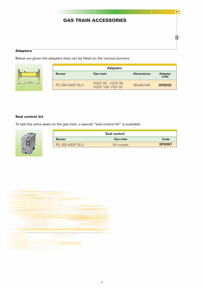
Adapters
Adaptercode
Seal control
Burner Code
RS 300-400/P BLU 3010367
Seal control kit
To test the valve seals on the gas train, a special “seal control kit” is available.
Adapters
Below are given the adapters than can be fitted on the various burners:
Burner Gas train Dimensions
3010222
Gas train
L = 400
18
VGDF 65 - VGDF 80VGDF 100- VGD 50 80x80x400
All models
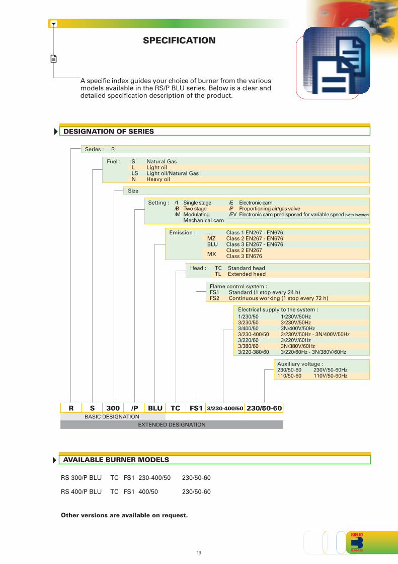
SPECIFICATION
A specific index guides your choice of burner from the variousmodels available in the RS/P BLU series. Below is a clear anddetailed specification description of the product.
DESIGNATION OF SERIES
Size
Fuel : S Natural GasL Light oilLS Light oil/Natural GasN Heavy oil
Series : R
RBASIC DESIGNATION
S 300 /P TC FS1 3/230-400/50 230/50-60
EXTENDED DESIGNATION
Emission : ... Class 1 EN267 - EN676MZ Class 2 EN267 - EN676BLU Class 3 EN267 - EN676
MXClass 2 EN267Class 3 EN676
Head : TC Standard headTL Extended head
BLU
Auxiliary voltage :230/50-60 230V/50-60Hz110/50-60 110V/50-60Hz
Electrical supply to the system :
Setting : /1 Single stage /E Electronic cam/B Two stage /P Proportioning air/gas valve/M Modulating /EV Electronic cam predisposed for variable speed (with inverter)
Mechanical cam
Flame control system : FS1 Standard (1 stop every 24 h)FS2 Continuous working (1 stop every 72 h)
1/230/50 1/230V/50Hz3/230/50 3/230V/50Hz3/400/50 3N/400V/50Hz3/230-400/50 3/230V/50Hz - 3N/400V/50Hz3/220/60 3/220V/60Hz3/380/60 3N/380V/60Hz3/220-380/60 3/220/60Hz - 3N/380V/60Hz
19
AVAILABLE BURNER MODELS
Other versions are available on request.
RS 300/P BLU TC FS1 230-400/50 230/50-60
RS 400/P BLU TC FS1 400/50 230/50-60
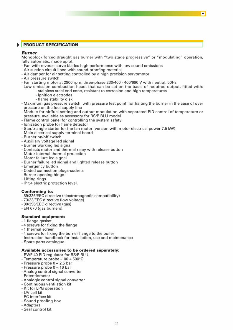
BurnerMonoblock forced draught gas burner with “two stage progressive” or “modulating” operation,fully automatic, made up of:- Fan with reverse curve blades high performance with low sound emissions- Air suction circuit lined with sound-proofing material- Air damper for air setting controlled by a high precision servomotor- Air pressure switch- Fan starting motor at 2900 rpm, three-phase 230/400 - 400/690 V with neutral, 50Hz- Low emission combustion head, that can be set on the basis of required output, fitted with:
- stainless steel end cone, resistant to corrosion and high temperatures- ignition electrodes- flame stability disk
- Maximum gas pressure switch, with pressure test point, for halting the burner in the case of overpressure on the fuel supply line
- Module for air/fuel setting and output modulation with separated PID control of temperature orpressure, available as accessory for RS/P BLU model
- Flame control panel for controlling the system safety- Ionization probe for flame detector- Star/triangle starter for the fan motor (version with motor electrical power 7,5 kW)- Main electrical supply terminal board- Burner on/off switch- Auxiliary voltage led signal- Burner working led signal- Contacts motor and thermal relay with release button- Motor internal thermal protection- Motor failure led signal- Burner failure led signal and lighted release button- Emergency button- Coded connection plugs-sockets- Burner opening hinge- Lifting rings- IP 54 electric protection level.
Conforming to:- 89/336/EEC directive (electromagnetic compatibility)- 73/23/EEC directive (low voltage)- 90/396/EEC directive (gas)- EN 676 (gas burners).
Standard equipment:- 1 flange gasket- 4 screws for fixing the flange- 1 thermal screen- 4 screws for fixing the burner flange to the boiler- Instruction handbook for installation, use and maintenance- Spare parts catalogue.
Available accessories to be ordered separately:- RWF 40 PID regulator for RS/P BLU- Temperature probe -100 ÷ 500°C- Pressure probe 0 ÷ 2.5 bar- Pressure probe 0 ÷ 16 bar- Analog control signal converter- Potentiometer- Analogic control signal converter- Continuous ventilation kit- Kit for LPG operation- UV cell kit- PC interface kit- Sound proofing box- Adapters- Seal control kit.
20
PRODUCT SPECIFICATION

21

22

23

ISO 9001 Cert. n. 0061
RIELLO S.p.A. - Via Ing. Pilade Riello, 5 - 37045 Legnago (VR) ItalyTel. ++39.0442630111 - Fax ++39.044221980
Internet: http://www.rielloburners.com - E-mail: [email protected]
Since the Company is constantly engaged in the production improvement, the aesthetic anddimensional features, the technical data, the equipment and the accessories can be changed.
This document contains confidential and proprietary information of RIELLO S.p.A.Unless authorised, this information shall not be divulged, nor duplicated in whole or in part.