Embed Size (px)
Citation preview
Low Level Operations & Computer Architecture
Low Level Operations & Computer Architecture 2015-16
In this topic you will learn about:
Use of Binary to represent and store data
Integers and real numbers Characters Instructions (machine code) Graphics (bit mapped and vector) Sound Video
Computer architecture (trends and implications)
Processor - Registers, ALU, Control unit Buses - Data bus, Address bus Main memory Cache memory Interfaces
Software and mobile devices
Virtual machines Emulators Mobile devices
Use of Binary to represent and store dataProcessors can only understand binary. Ultimately, everything that is processed by a computer is handled in one of two states, 1 or 0.
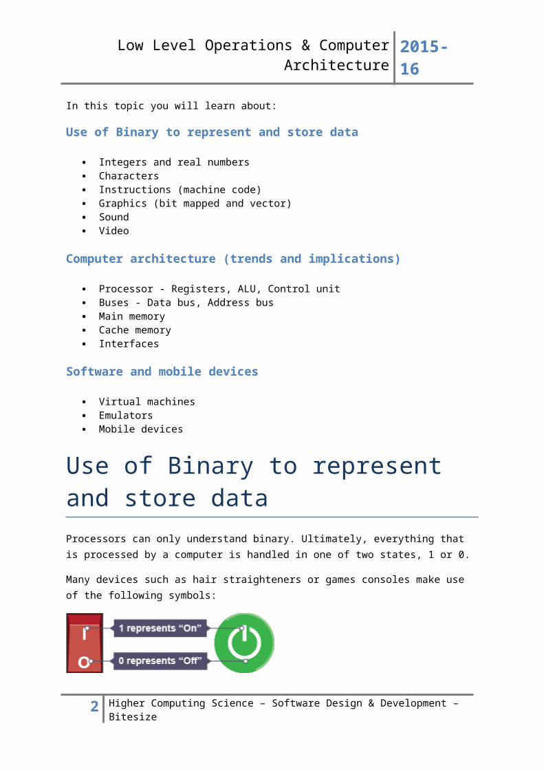
Many devices such as hair straighteners or games consoles make use of the following symbols:
The number 1 represents on and the number 0 represents off. Binary is used to represent whole numbers so that they can be understood by the processor.
2 Higher Computing Science – Software Design & Development – Bitesize
Low Level Operations & Computer Architecture 2015-16
IntegersAn integer is a whole number. Integers can be positive numbers or negative numbers. The number 173 can be represented in binary as:
10101101
Binary works using a number system that is based on powers of 2. To understand why 10101101 is the same as 173 look at the following table:
128 64 32 16 8 4 2 127 26 25 24 23 22 21 20
1 0 1 0 1 1 0 1ON OFF ON OFF ON ON OFF ON
When adding up all of the values that are on, the following sum is created:
128 + 32 + 8 + 4 + 1 = 173
In this example we are using 8 bits to represent a number. If we use 8 bits we can represent any number between 0 and 255.
If all of the values are off, the number is 0:
128 64 32 16 8 4 2 127 26 25 24 23 22 21 20
0 0 0 0 0 0 0 0OFF OFF OFF OFF OFF OFF OFF OFF
If all of the values are on, the number is 255:
128 64 32 16 8 4 2 127 26 25 24 23 22 21 20
1 1 1 1 1 1 1 1ON ON ON ON ON ON ON ON
128 + 64 + 32 + 16 + 8 + 4 + 2 + 1 = 255
3 Higher Computing Science – Software Design & Development – Bitesize
Low Level Operations & Computer Architecture 2015-16
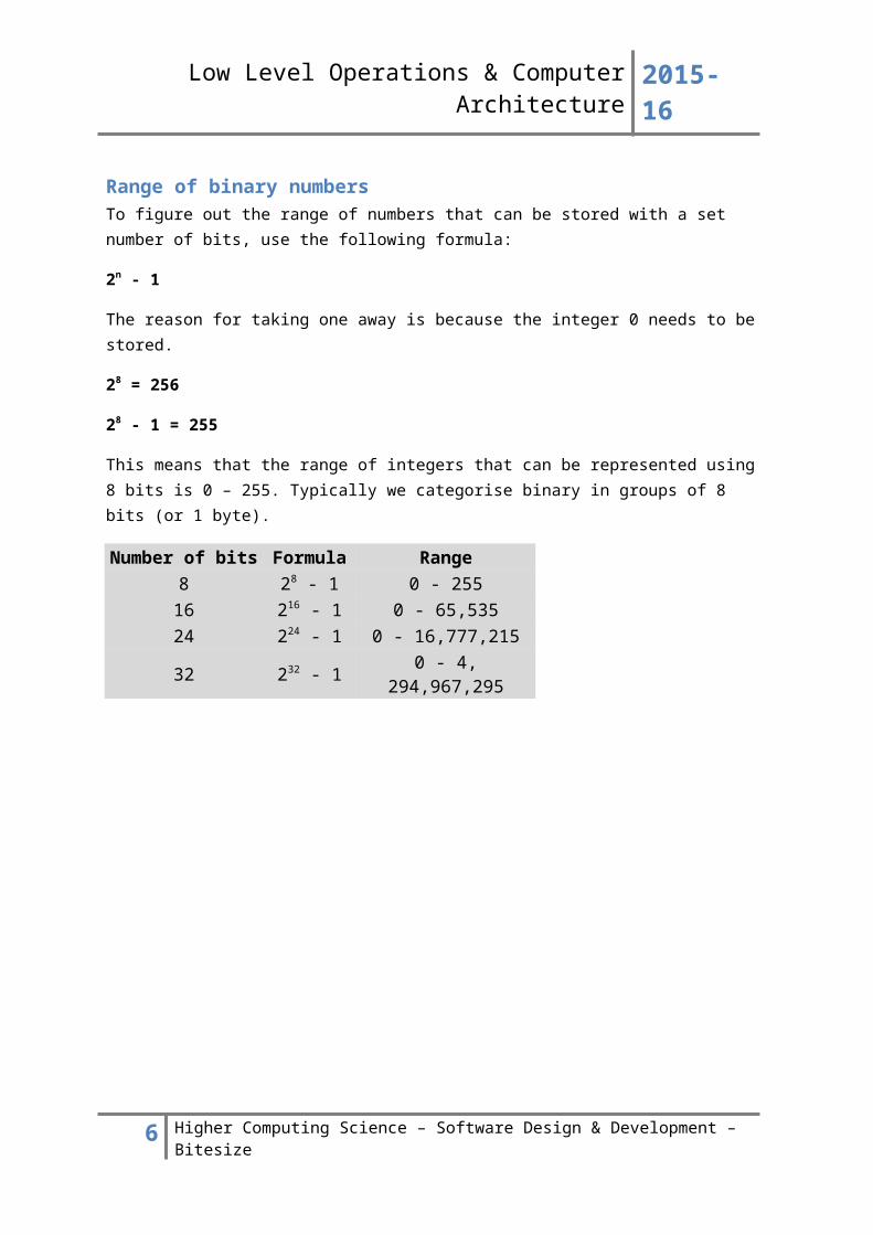
Range of binary numbersTo figure out the range of numbers that can be stored with a set number of bits, use the following formula:
2n - 1
The reason for taking one away is because the integer 0 needs to be stored.
28 = 256
28 - 1 = 255
This means that the range of integers that can be represented using 8 bits is 0 – 255. Typically we categorise binary in groups of 8 bits (or 1 byte).
Number of bits Formula Range8 28 - 1 0 - 25516 216 - 1 0 - 65,53524 224 - 1 0 - 16,777,21532 232 - 1 0 - 4, 294,967,295
4 Higher Computing Science – Software Design & Development – Bitesize
Low Level Operations & Computer Architecture 2015-16
Representing negative integersNegative numbers can also be represented in binary. The name of the system most commonly used to represent and handle negative numbers is '2s Complement'.
2's Complement - most common technique
To use this technique you must understand the rules of binary arithmetic:-
0 + 0 = 0
1 + 0 = 1
0 + 1 = 1
0 + 0 = 10 (remember that 10 in binary means “1 in the 2s column and 0 in the 0s column”)
The steps to write a negative number are:-
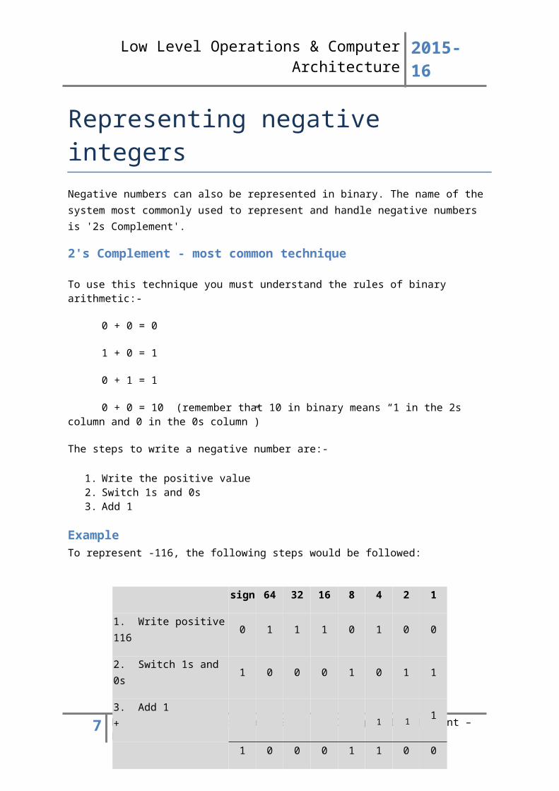
1. Write the positive value 2. Switch 1s and 0s 3. Add 1
ExampleTo represent -116, the following steps would be followed:
So 10001100 = -116
2’s Complement – alternative method that your teacher will demonstrate
1. Write the positive value2. Start at the 1s column. Check each value and switch the 1s and 0s after the first 1.
5 Higher Computing Science – Software Design & Development – Bitesize
sign 64 32 16 8 4 2 1
1. Write positive 116 0 1 1 1 0 1 0 0
2. Switch 1s and 0s 1 0 0 0 1 0 1 1
3. Add 1 + 1
1 0 0 0 1 1 0 0
11
Low Level Operations & Computer Architecture 2015-16
Real numbersReal numbers are numbers that include fractions. For example, 123.75 is a real number. This type of number is known as a floating point number in Computing Science.
The process of storing floating point numbers is fairly complex and requires knowledge beyond that covered in Higher Computing Science. A computer will use either single precision or double precision to store a real number.
Regardless of the method used, all floating point numbers are stored using a Mantissa and an Exponent. The following example is used to illustrate the role of the Mantissa and the Exponent. It does not fully reflect the computers method for storing a real numbers using single or double precision but conveys the concept at an appropriate level.
If we take 123.75 we can represent this number using mathematical scientific notation as:
1.2375
M X 10E
Multiplying by ten to the power of two moves the values up two places so that the number 123 is beyond the decimal point, while the number 75 now comes immediately after the decimal point. In this example our Mantissa is 01.2375 and the Exponent is 2.
To represent the same value in binary we apply the following rules:
Represent the number 123.75 as:
64 32 16 8 4 2 1 0.5 0.251 1 1 1 0 1 1 1 1
The section shown in green may be a new concept. Traditionally we stop at 1 but for the purpose of understanding real numbers, continue to half the previous value so that you can represent 1/2, 1/4, 1/8, 1/16 and so on:
64 + 32 + 16 + 8 + 2 + 1 + 0.5 + 0.25 = 123.75
If we take the number that we have created in binary but remove the decimal point we are left with the Mantissa:
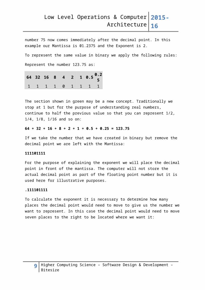
111101111
For the purpose of explaining the exponent we will place the decimal point in front of the mantissa. The computer will not store the actual decimal point as part of the floating point number but it is used here for illustrative purposes.
.111101111
6 Higher Computing Science – Software Design & Development – Bitesize
Low Level Operations & Computer Architecture 2015-16
To calculate the exponent it is necessary to determine how many places the decimal point would need to move to give us the number we want to represent. In this case the decimal point would need to move seven places to the right to be located where we want it:
4 + 2 + 1 = 7
In order to represent 123.75 the mantissa would be 111101111 and the exponent would be 111. We could think of this as:
M = 2E (where M represents the mantissa and E represents the exponent)
.111101111 x 2111
In reality the process is more complicated with some more steps needed to have a true reflection of single precision or double precision representation. However, as a concept the example shown should help to explain the need for a Mantissa and an exponent.
It is possible to improve the accuracy of a floating point number by increasing the number of bits devoted to the mantissa. The range of numbers held can be increased if more bits are devoted to the storage of the exponent.
There will always be a trade-off between accuracy and range when storing real numbers using floating point notation, as there will always be a set number of bits allocated to storing real numbers with the potential to increase or decrease the number of bits used for the mantissa against the number of bits used for the exponent.
7 Higher Computing Science – Software Design & Development – Bitesize
Low Level Operations & Computer Architecture 2015-16
CharactersCharacters can also be represented in binary. Characters are usually grouped together in what is known as a character set. A character set is more than just the letters that form a language.
Characters include alphanumeric data (letters and numbers), symbols (*, &, : etc.) and control characters (Shift, Escape etc.).
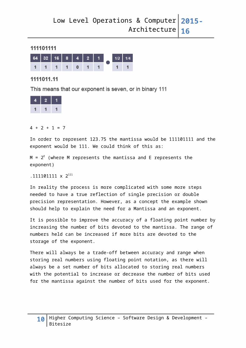
ASCIIASCII uses 8 bits to represent a character. However, one of the bits is used to perform a parity check. A parity check is a form of error checking. Because one bit is set aside to represent a parity bit, ASCII represents 128 characters with 8 bits rather than 256. The ASCII code for lower case z is 122 and is shown below:
Parity Bit 64 32 16 8 4 2 1
0 1 1 1 1 0 1 0
Extended ASCIIIt is possible to disregard the use of a parity bit to allow ASCII to represent 256 characters. This is known as extended ASCII. There are different versions of extended ASCII in use.
Key points
ASCII uses 8 bits to represent a character ASCII can represent 128 characters ASCII sets the most significant bit as a parity bit Extended ASCII can allow for the representation of 256 characters and disregards that use of
a parity bit ASCII is less demanding on memory use than Unicode
UnicodeThe main issue with using ASCII or Extended ASCII is that 128 or 256 characters limit the amount of character sets that can be held. Representing the character sets for several different language structures is not possible in ASCII, there are just not enough available characters.
Unicode was created to overcome this issue. Unicode uses 16 bits to represent each character. This means that Unicode is capable of representing 65, 536 different characters and a much wider range of character sets.
Key points:
Unicode can represent 65,536 charaters Unicode uses 16 bits to represent each character Unicode can represent a greater range of character sets than ASCII
8 Higher Computing Science – Software Design & Development – Bitesize
Low Level Operations & Computer Architecture 2015-16
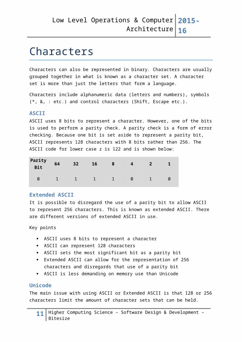
Bit-mapped graphicsBit-mapped graphics store every pixel necessary to represent an image. Photographs are stored as bit mapped images.
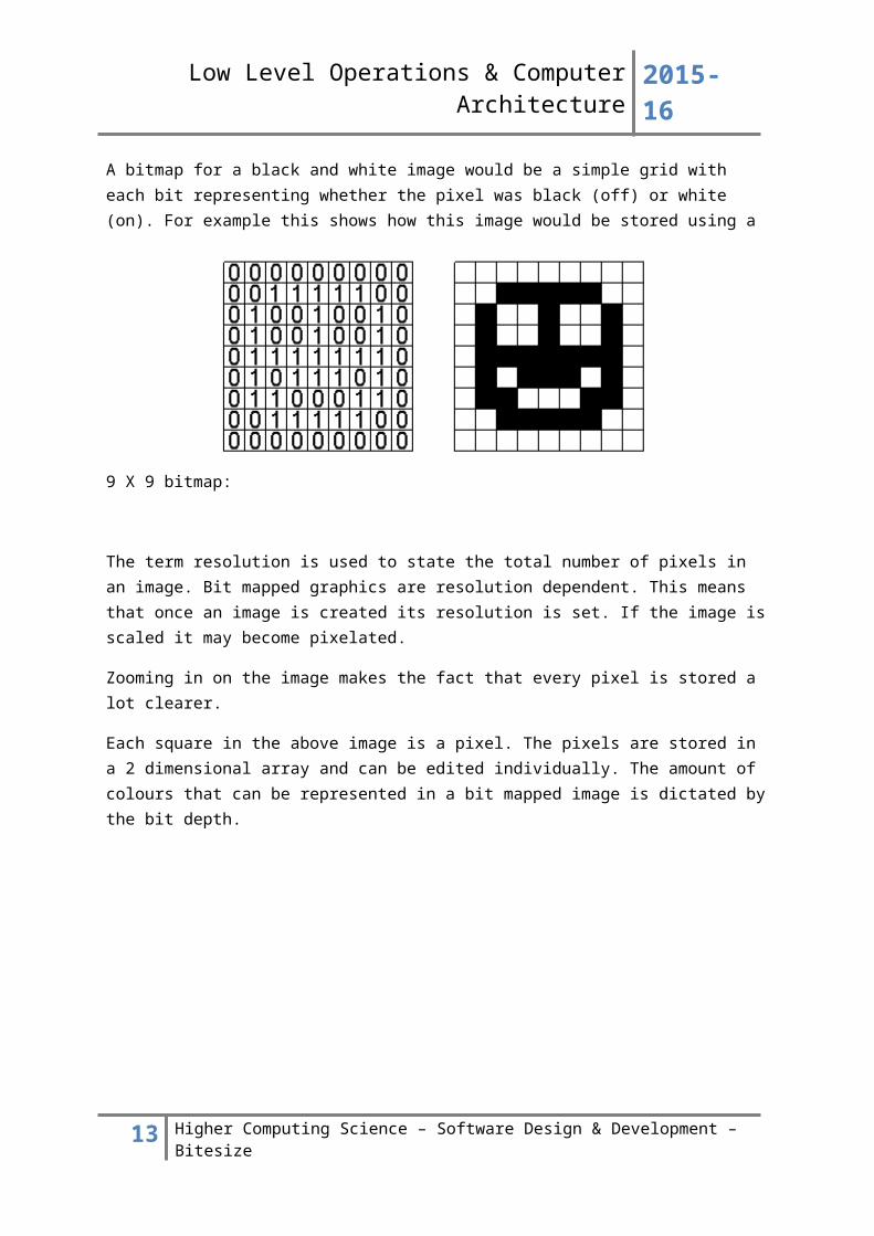
A bitmap for a black and white image would be a simple grid with each bit representing whether the pixel was black (off) or white (on). For example this shows how this image would be stored using a 9 X 9 bitmap:
The term resolution is used to state the total number of pixels in an image. Bit mapped graphics are resolution dependent. This means that once an image is created its resolution is set. If the image is scaled it may become pixelated.
Zooming in on the image makes the fact that every pixel is stored a lot clearer.
Each square in the above image is a pixel. The pixels are stored in a 2 dimensional array and can be edited individually. The amount of colours that can be represented in a bit mapped image is dictated by the bit depth.
9 Higher Computing Science – Software Design & Development – Bitesize
Low Level Operations & Computer Architecture 2015-16
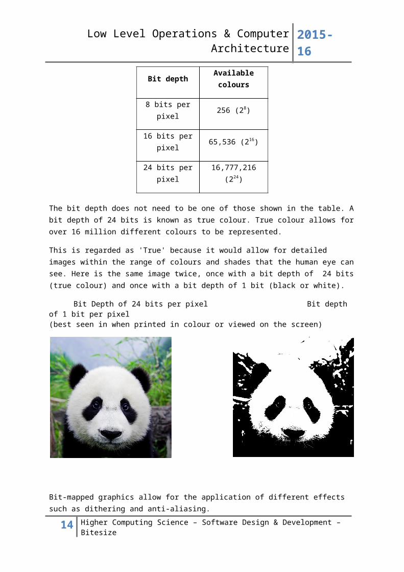
The bit depth does not need to be one of those shown in the table. A bit depth of 24 bits is known as true colour. True colour allows for over 16 million different colours to be represented.
This is regarded as 'True' because it would allow for detailed images within the range of colours and shades that the human eye can see. Here is the same image twice, once with a bit depth of 24 bits (true colour) and once with a bit depth of 1 bit (black or white).
Bit Depth of 24 bits per pixel Bit depth of 1 bit per pixel(best seen in when printed in colour or viewed on the screen)
Bit-mapped graphics allow for the application of different effects such as dithering and anti-aliasing.
DitheringDithering is a technique used to try to create colours that aren't present in the image by placing different coloured pixels close together. The aim is to trick the eye into seeing a colour that is actually a combination of the other colours in the image.
Anti-aliasingWhen jagged lines appear in an image it is possible to use anti-aliasing to make lines appear smoother. This involves changing the colour or alignment of pixels around the jagged line to try and reduce the stair-case effect.
10 Higher Computing Science – Software Design & Development – Bitesize
Bit depth Available colours
8 bits per pixel 256 (28)
16 bits per pixel 65,536 (216)
24 bits per pixel 16,777,216 (224)
Low Level Operations & Computer Architecture 2015-16
Compression (from Media Types topic)Compression is necessary for two reasons:
1. To reduce the file size of an image so that it is less demanding in terms of storage and memory use
2. To reduce the file size of an image to allow for faster transmission over a network
There are various forms of compression that can be used on bit mapped graphics depending on the file format used. Two common techniques are Run Length Encoding (RLE) and Lempel, Ziv, Welch (LZW).
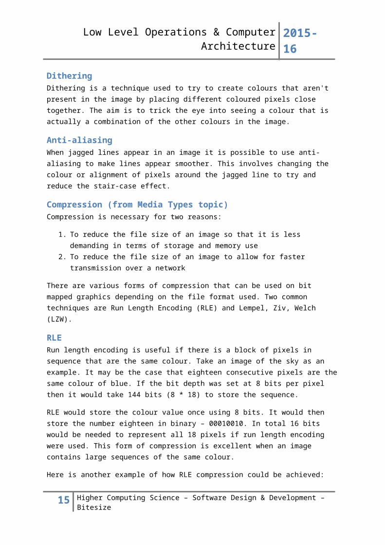
RLERun length encoding is useful if there is a block of pixels in sequence that are the same colour. Take an image of the sky as an example. It may be the case that eighteen consecutive pixels are the same colour of blue. If the bit depth was set at 8 bits per pixel then it would take 144 bits (8 * 18) to store the sequence.
RLE would store the colour value once using 8 bits. It would then store the number eighteen in binary – 00010010. In total 16 bits would be needed to represent all 18 pixels if run length encoding were used. This form of compression is excellent when an image contains large sequences of the same colour.
Here is another example of how RLE compression could be achieved:
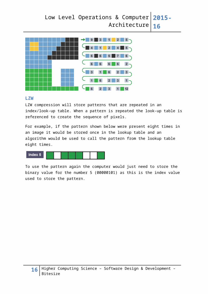
LZWLZW compression will store patterns that are repeated in an index/look-up table. When a pattern is repeated the look-up table is referenced to create the sequence of pixels.
For example, if the pattern shown below were present eight times in an image it would be stored once in the lookup table and an algorithm would be used to call the pattern from the lookup table eight times.
To use the pattern again the computer would just need to store the binary value for the number 5 (00000101) as this is the index value used to store the pattern.
11 Higher Computing Science – Software Design & Development – Bitesize
Low Level Operations & Computer Architecture 2015-16
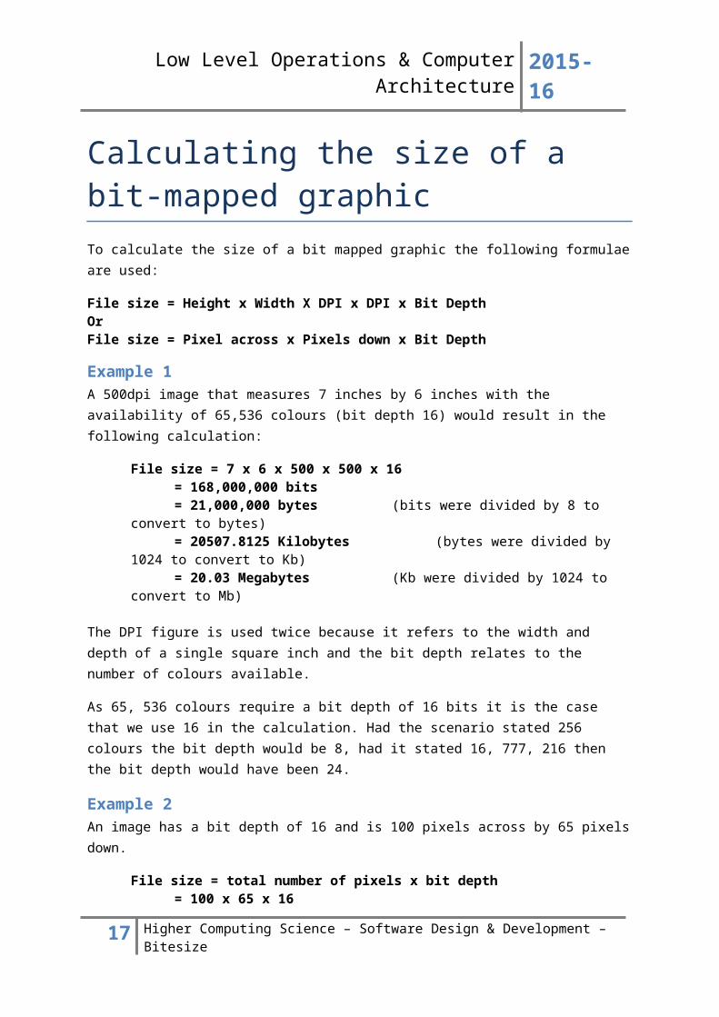
Calculating the size of a bit-mapped graphicTo calculate the size of a bit mapped graphic the following formulae are used:
File size = Height x Width X DPI x DPI x Bit DepthOr File size = Pixel across x Pixels down x Bit Depth
Example 1A 500dpi image that measures 7 inches by 6 inches with the availability of 65,536 colours (bit depth 16) would result in the following calculation:
File size = 7 x 6 x 500 x 500 x 16 = 168,000,000 bits = 21,000,000 bytes (bits were divided by 8 to convert to bytes)= 20507.8125 Kilobytes (bytes were divided by 1024 to convert to Kb)= 20.03 Megabytes (Kb were divided by 1024 to convert to Mb)
The DPI figure is used twice because it refers to the width and depth of a single square inch and the bit depth relates to the number of colours available.
As 65, 536 colours require a bit depth of 16 bits it is the case that we use 16 in the calculation. Had the scenario stated 256 colours the bit depth would be 8, had it stated 16, 777, 216 then the bit depth would have been 24.
Example 2An image has a bit depth of 16 and is 100 pixels across by 65 pixels down.
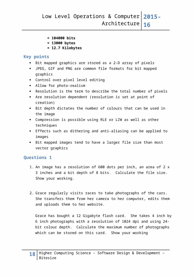
File size = total number of pixels x bit depth= 100 x 65 x 16= 104000 bits = 13000 bytes = 12.7 Kilobytes
Key points Bit mapped graphics are stored as a 2-D array of pixels JPEG, GIF and PNG are common file formats for bit mapped graphics Control over pixel level editing Allow for photo-realism Resolution is the term to describe the total number of pixels Are resolution dependent (resolution is set at point of creation) Bit depth dictates the number of colours that can be used in the image Compression is possible using RLE or LZW as well as other techniques Effects such as dithering and anti-aliasing can be applied to images Bit mapped images tend to have a larger file size than most vector graphics
12 Higher Computing Science – Software Design & Development – Bitesize
Low Level Operations & Computer Architecture 2015-16
Questions 1
1. An image has a resolution of 600 dots per inch, an area of 2 x 3 inches and a bit depth of 8 bits. Calculate the file size. Show your working.
2. Grace regularly visits races to take photographs of the cars. She transfers them from her camera to her computer, edits them and uploads them to her website.
Grace has bought a 12 Gigabyte flash card. She takes 4 inch by 6 inch photographs with a resolution of 1024 dpi and using 24-bit colour depth. Calculate the maximum number of photographs which can be stored on this card. Show your working
13 Higher Computing Science – Software Design & Development – Bitesize
Low Level Operations & Computer Architecture 2015-16
Vector graphicsVector graphics are stored as a list of attributes. The attributes are used by the computer to create the graphic. Rather than storing the data for each pixel, the computer will generate an object by looking at its attributes.
The rectangle shown above was created using the following list of attributes. The attributes are shown in bold, their values come immediately after the = sign.
Because the object is created from a list of attributes it is easy to scale vector graphics without having to worry about the resolution. To alter the size of the rectangle a designer would just need to change the values for height and width.
This would often happen by simply increasing the size of the image by using the pointer within a graphics package. It is also possible to layer objects on top of one another without losing the data that is underneath (as would be the case in bit mapped graphics).
Changing the complexity of a vector graphics image will change its file size because of the additional information which needs to be stored.
Some bitmap packages use several bitmaps to allow the user to create separate layers as part of an image, however these will always be combined into a single bitmap when the file is saved.
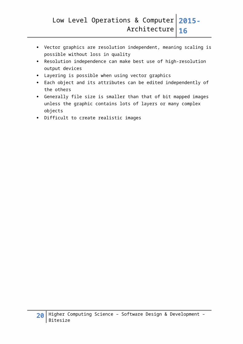
Key points Vector graphic are stored as a list of attributes Vector graphics are resolution independent, meaning scaling is possible without loss in
quality Resolution independence can make best use of high-resolution output devices Layering is possible when using vector graphics Each object and its attributes can be edited independently of the others Generally file size is smaller than that of bit mapped images unless the graphic contains lots
of layers or many complex objects Difficult to create realistic images
14 Higher Computing Science – Software Design & Development – Bitesize
Low Level Operations & Computer Architecture 2015-16
Practical Task - Comparing the file size of bitmapped and vector graphics1. Create a simple image such as a circle intersecting a rectangle in a bitmapped painting package. Note the size of the file when saved.
2. Create the same image as far as possible using a vector graphics package and compare the size of the saved file with that created by the bitmapped package.
3. Edit the bitmapped image to add more detail and save it. Does the file size change?
4. Add some more detail to the vector graphics file and see if the file size changes when you save it.
5. Explain your findings.
15 Higher Computing Science – Software Design & Development – Bitesize
Low Level Operations & Computer Architecture 2015-16
SoundSound comes in one of two forms, synthesised or digitised.
Synthesised soundSynthesised sound is generated by a sound card and does not support vocals. MIDI files are an example of synthesised sound. MIDI files are stored in a similar way to vector graphics.
Attributes of the sound such as tempo, pitch and amplitude are stored and the sound card will output a sound in light of the attributes that are processed and converted to binary form from the MIDI file.
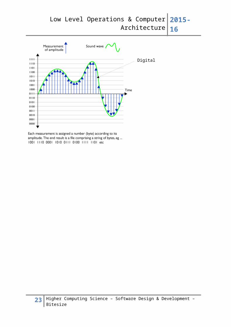
Digitised soundDigitised sound is sound that has been captured by a microphone and sound card. These sounds are received as analogue signals which are then converted to a digital binary pattern for storage and processing purposes. Prior to capturing a digitised sound the user will select a sampling frequency and sampling depth.
Sampling frequency dictates how many samples are taken per second and is measured in KHz. Sampling depth dictates how many bits are used to store each sample, much like the concept of bit depth in relation to a bit mapped graphic.
16 Higher Computing Science – Software Design & Development – Bitesize
Digital samples
Analogue sound wave
Low Level Operations & Computer Architecture 2015-16
Bit RateAs a sound is played, digital signals have to be converted to analogue in order for us to hear it. The bit rate is the number of bits each second that have to be processed in order for a digital sound to be played.
If the sound is high quality, then there will be a greater number of bits as there will be a greater number of samples each second to be converted back to analogue and each sample itself will be a larger number of bits as the sampling depth will be greater.
If a digital sound is being streamed over a computer network then the number of bits each second is important. If the number of bits each second is very high then this will also place demands on the computer hardware, as it all needs to be processed.
The bit rate for sounds can be calculated as follows:
Bit Rate (bits per second) = sampling depth (bits) * sampling frequency (Hz)
ExampleA CD quality sound recorded using a sampling frequency of 44KHz and a sampling depth of 16 bits.
Solution:Bit rate = 44000 * 16
= 704000 bits per second= 704K bits per second
MP3 compressionMP3 is a common file format for sound files. MP3 files allow for compression by:
Where a sound is masked by more dominant sounds: two sounds that are very similar that are played at the same time would only be stored once, with the higher frequency sound preferred to the lower frequency
Sounds out with the dynamic range (hearing range) that can be heard by humans are removed
It is not as simple as saying that a quieter sound will be removed. If you imagine an MP3 file of a song by a heavy metal band you will appreciate that it is too simplistic to suggest that quieter sounds are removed, as there is often an artistic need to maintain the presence of lower background sound.
However, it is important to understand that two sounds which play at the same time at almost the same frequency will result in the storage of only one of the two sounds where the sound is similar. Sounds which are not similar but are played at a slightly lower frequency would be retained.
17 Higher Computing Science – Software Design & Development – Bitesize
Low Level Operations & Computer Architecture 2015-16
VideoVideos are made up of a series of frames (images) that play one after the other very quickly. Each frame of a video is stored as an image.
The section on bit-mapped graphics applies to the theory of storing a frame. While a frame rate of 24 frames per second is regarded as a standard there are now demands for some video formats capable of playing 120 frames per second (such as Ultra High Definition Television).
The more frames per second, the greater the quality of the playback. However, the knock on effect of a high frame rate is that the video will be large in relation to file size and place extra demands on RAM/VRAM and the CPU/GPU when processing.
Graphics cards are responsible for processing video data on a computer system. Most modern graphics cards will have a dedicated GPU processor (Graphics Processing Unit) and VRAM (Video RAM).
The demands that video files were placing on the central processing unit and main memory meant that it became more efficient to handle video processing on the graphics card where possible.
MPEG CompressionMPEG is a video file format that makes use of both interframe and intraframe compression.
Interframe compression makes use of key frames. Key frames are stored at set intervals. The frames between each key frame are examined and if there is a change from frame to frame then only the part of the frame that has changed is kept. This is called a delta frame.
Intraframe compression is the process of storing key frames as compressed JPEG image files. The JPEG file format will compress frames using a technique called Huffman encoding.
18 Higher Computing Science – Software Design & Development – Bitesize

Low Level Operations & Computer Architecture 2015-16
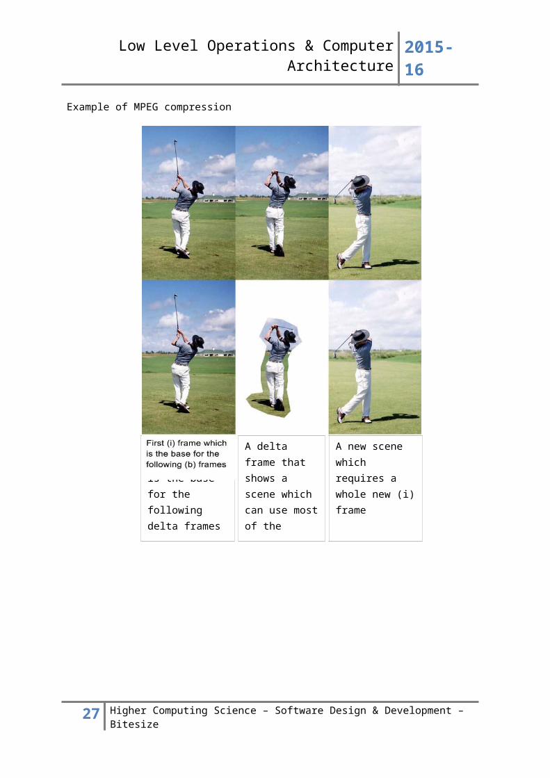
Example of MPEG compression
19 Higher Computing Science – Software Design & Development – Bitesize
First (i) frame which is the base for the following delta frames
A delta frame that shows a scene which can use most of the information from the previous (i) frame
A new scene which requires a whole new (i) frame
Low Level Operations & Computer Architecture 2015-16
Computer architecture (trends and implications)Computer architecture is a term used to describe the different aspects of hardware that are required to allow a computer system to operate:
Processor - Registers, ALU, Control unit Buses - Data Bus, Address Bus Main Memory Cache Memory Interfaces
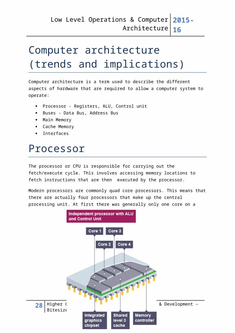
ProcessorThe processor or CPU is responsible for carrying out the fetch/execute cycle. This involves accessing memory locations to fetch instructions that are then executed by the processor.
Modern processors are commonly quad core processors. This means that there are actually four processors that make up the central processing unit. At first there was generally only one core on a processor. This evolved to become dual-core (two processors) and now quad-core.
20 Higher Computing Science – Software Design & Development – Bitesize
Low Level Operations & Computer Architecture 2015-16
The more processors present, the greater the number of tasks that can be processed simultaneously. As processor technology evolves it is anticipated that octa-core processors (8 processors) will become more common.
Mobile phone companies have started to roll out the use of octa-core processors. However, the technology is not sufficiently efficient to justify wide spread use at the moment.
There are three main components to every processor:
Registers ALU Control unit
RegistersRegisters are storage location on the processor that are used to store data, instructions or addresses. Data/instructions/addresses that are needed during the fetch/execute cycle are held within registers.
Registers offer the fastest access time of any storage location as they are part of the actual processor. There are a variety of registers with different purposes, for example:-
Program Counter stores the address of the next instruction to be fetched Memory Address Register stores the address of the memory location where data is to be
read from or written to Accumulator stores the (intermediate) results of arithmetic and logic operations Memory Data Register stores the data or instructions transferred between the CPU and
memory Instruction Register stores the current instruction being decoded and executed
ALUThe Arithmetic and Logic Unit is used by the processor to carry out operations that usef:
Logical operations such as AND, OR, NOT Arithmetic operations such as +, -, *, /
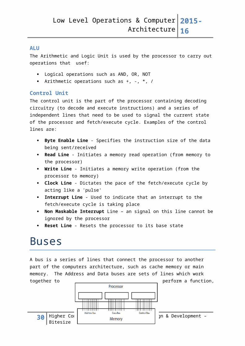
Control UnitThe control unit is the part of the processor containing decoding circuitry (to decode and execute instructions) and a series of independent lines that need to be used to signal the current state of the processor and fetch/execute cycle. Examples of the control lines are:
Byte Enable Line - Specifies the instruction size of the data being sent/received Read Line - Initiates a memory read operation (from memory to the processor) Write Line - Initiates a memory write operation (from the processor to memory) Clock Line - Dictates the pace of the fetch/execute cycle by acting like a 'pulse' Interrupt Line - Used to indicate that an interrupt to the fetch/execute cycle is taking place Non Maskable Interrupt Line – an signal on this line cannot be ignored by the processor Reset Line - Resets the processor to its base state
21 Higher Computing Science – Software Design & Development – Bitesize
Low Level Operations & Computer Architecture 2015-16
BusesA bus is a series of lines that connect the processor to another part of the computers architecture, such as cache memory or main memory. The Address and Data buses are sets of lines which work together to perform a function, however the control bus is really just a collection of control lines with separate functions.
Address BusThe address bus is uni-directional, meaning that it passes an address one way, from the CPU to RAM. The sole purpose of an address bus is to identify the address of the location in cache or main memory that is to be read from or written to. Each location in memory will have its own unique binary address, this is known as addressability.
The total number of memory locations which can be addressed by the processor is determined by the number of lines in the address bus. The total number of memory locations will be 2 to the power of the number of lines in the address bus:
• 16 lines = 216 possible memory locations (i.e. 65,536)
• 32 lines = 232 possible memory locations (i.e. 4294967296)
Data BusThe data bus is bi-directional because it can carry data to main memory from the processor and vice versa. The data bus will transfer data to/from the address that is indicated by the address bus.
The term “word size” describes the width of the data bus. Word size indicates the amount of data that can be carried by the data bus at a point in time. At the moment new processors will usually have a word size of 64 bits.
This diagram shows how the buses are connected to the processor:-
22 Higher Computing Science – Software Design & Development – Bitesize
Memory Address Register Memory Data Register
Low Level Operations & Computer Architecture 2015-16
Fetch/Execute cycleThe term” fetch/execute cycle” is used to describe the processor receiving an instruction from memory and carrying out the instruction.
During the fetch/execute cycle the Control Unit, Data Bus and Address Bus are all in use.
Detailed version of the Fetch/Execute cycle1. Transfer the contents of the Program Counter to Memory Address Register
2. Increment the Program Counter
3. Activate Read line (thereby transferring instruction to the Memory Data Register)
4. Transfer contents of Memory Data Register to the Instruction Register ready for decoding
5. Decode Instruction
6. Execute Instruction
The execute step might involve e.g.:-
carrying out a simple instruction to increment a register an instruction to load data from a memory location and add it to the accumulator instruction to place a new memory location into the program counter
Simplified version of the Fetch/Execute cycle1. Processor sets up address bus with the required memory address (which is stored in the
Memory Address Register)
2. Control unit in the processor activates the read line on the control bus
3. Contents of the memory location are released onto the data bus and copied into the Memory Data Register
4. Instruction is passed from the Memory Data register to the Control unit to be decoded and executed
23 Higher Computing Science – Software Design & Development – Bitesize
Low Level Operations & Computer Architecture 2015-16
Reading data from memoryWhen a memory read operation occurs, data is read from a memory address and taken to the processor. Here are the steps involved:-
1. Processor sets up address bus with the required memory address (which is stored in the Memory Address Register)
2. Control unit in the processor activates the read line on the control bus
3. Contents of the memory location are released onto the data bus and copied into the Memory Data Register
Writing to data to memoryWhen a memory write operation occurs, data is taken from the processor to memory. Here are the steps involved:-
1. Processor sets up address bus with the required memory address - it is placed in the MAR
2. Processor sets up data bus with the value to be written to memory – it is placed in the MDR
3. Control unit activates the write line on the control bus
4. Contents of the MDR are transferred to the required memory location
The roles of the buses during the fetch execute cycleThe control unit will dictate the clock speed of the fetch/execute cycle as well as activating either the read or write line.
The address bus will hold the address that is being accessed in main memory and the data bus will either transfer the contents of the memory address to the processor, or will transfer data from the processor to the memory address.
24 Higher Computing Science – Software Design & Development – Bitesize
Low Level Operations & Computer Architecture 2015-16
Main memoryMain memory is often used interchangeably with the term RAM. Before understanding the concept of main memory it is necessary to understand the role of Read Only Memory (ROM) and Flash Memory.
ROMROM chips are manufactured to contain non-editable, permanent data. ROM chips are used to initiate system start up. In recent years editable ROM has started to become more popular.
This form of ROM allows for altering of the instructions that are stored permanently. In relation to smartphones and tablet devices the term ROM does not refer to a dedicated ROM chip but to a section of Flash memory that operates like ROM.
Flash MemoryFlash memory is really a form of editable ROM. The contents are non-volatile - this means that what is held in flash memory will not necessarily be lost when a system is shut down.
Mobile phones and tablets make use of partitions in flash memory. To create a partition means to set aside a section of flash memory for a specific purpose which is treated as independent of the other areas of flash memory.
Part of flash memory is set aside to act in the way that traditional ROM would act, so the operating system would be held in this partition. Phone users do not have access to the files held within this area and cannot edit them without invalidating their warranty.
When a software update is released by a manufacturer it will be given access to this area of flash memory. The relevant updating can then take place without the user ever having access to the protected area.
When apps are downloaded they are stored in a section of flash memory that operates like a traditional backing storage system. The files are held here and accessed when necessary. When an app is in use, it will either be held in RAM if present or in a section of flash memory that is set aside to operate like traditional RAM.
Increased Flash memory use is starting to blur the lines of traditional memory setup. At the moment, use as a form of ROM and backing storage is more common than use as a form of RAM but some devices utilise flash memory in this way as well.
Main Memory (RAM)RAM chips are critical aspects of a computer system. RAM is used to hold programs that have been loaded and all data required for an active program to run. The data is transferred from backing storage to RAM and held there until it is no longer required by the processor. The processor will use the address bus and data bus to access the contents of memory locations in main memory. When the system is shut down the contents of RAM are cleared, this means that RAM is regarded as volatile.
25 Higher Computing Science – Software Design & Development – Bitesize
Low Level Operations & Computer Architecture 2015-16
Cache memoryCache memory is used to improve system performance. Cache memory operates in the same way as RAM in that it is volatile – this means that when the system is shutdown the contents of cache memory are cleared. Cache memory allows for faster access to data for three reasons:
Cache uses Static RAM whereas Main Memory (RAM) uses dynamic RAM Cache stores pre-fetched instructions (see below) Cache attempts to store commonly used instructions
Static RAMThe use of static RAM means that the access time is faster when retrieving data from Cache over RAM. Static RAM does not need to be refreshed in the same way that dynamic RAM does. The process of refreshing RAM means that it takes longer to retrieve data from main memory.
Pre-fetched instructionsCache memory will copy the contents of some data held in RAM (i.e. pre-fetch instructions). To simplify the process it works on the understanding that most programs store data in sequence. If the processor is currently processing data from locations 0 – 32, cache memory will copy the contents of locations 33- 64 in anticipation that they would be needed next.
Commonly used instructions
Cache memory will also store frequently used instructions that can accessed faster than they could be if held in main memory (RAM).
Checking Cache then RAMWhen the processor initiates a memory read it will check cache memory first. When checking it will either encounter a cache hit or a cache miss. In the case of this example, if the processor was hoping to receive the contents of the data that had been in RAM location 37 then it would find those contents in cache memory. This is a cache hit.
If it were trying to find the contents of location 112 it would encounter a cache miss, meaning it would attempt to read the data from RAM after it had unsuccessfully tried cache memory.
26 Higher Computing Science – Software Design & Development – Bitesize
11001101
Serial to Parallel
Low Level Operations & Computer Architecture 2015-16
InterfacesInterfaces are used to allow peripheral devices and hardware to connect to a computer system. The connection allows data to be sent and received by the processor and the connected device.
The main purpose of an interface is to allow for differences in speed and the way that data is handled by each peripheral device. Connections can be wired or wireless. USB is a common example of a standard interface.
Interfaces are responsible for:
Voltage conversion. The processor is only designed to cope with a limited range of voltages. If a peripheral works at a higher voltage then some conversion would be necessary
Status signals. Status signals exist that relate to the transfer and handling of data. If a peripheral needs to send a status signal the interface would be responsible for this e.g. a printer may need to inform the processor that it is low on ink or a hard disk drive may need to send data about the position of the read/write heads
Data format conversion. Some devices send and receive data in serial format and others in parallel. If conversion from serial to parallel or parallel to serial one is needed then the interface would be responsible for this.
--1----0----1----1----0----0----1----1
Similarly some data is held in analogue and some in digital format so analogue to digital or digital to analogue data format conversion may be needed.
Temporary Data Storage in transit (buffering). The processor and the peripheral transfer data at different speeds so the interface may store data until the processor or peripheral is ready to receive it
Transmitting control signals. The processor may need to send control signals to a hard disk drive in order to read a file from a specific location on the disk.
Device Selection. Since several peripherals may be connected to the data bus the processor needs to be able to send a code to identify which interface a piece of data is intended for .
An interface will often be a combination of hardware and software. For instance a graphics card or a sound card will often require software drivers to be installed as well as the card itself.
27 Higher Computing Science – Software Design & Development – Bitesize
Low Level Operations & Computer Architecture 2015-16
Software and mobile devicesAs computing science has evolved it has become more common to replicate aspects of different systems within another system. Mobile devices are now more popular than ever with a range of users having access to smartphones and tablet devices. There are three aspects of software and hardware evolution that this section will address:
virtual machines emulators mobile devices
Virtual machinesVirtual machines allow users to access a virtual operating system while using their own operating system. For example, in the early 1990s there were lots of computer games available for Windows operating systems. If you owned an Apple computer it was not always possible to buy and install the computer game on the Apple operating system.
The only way round this was to install a virtual version of the Windows operating system on the Apple system. When the user wanted to play the game they would launch the virtual Windows machine and install the software there.
The actual Apple computer would have its own operating system running at all times but during the game the virtual windows system would also be running. It would not be possible to play the game without running the virtual machine to do so.
In general domestic use, the need for virtual systems is not as common anymore, as many software development companies create portable software that can be purchased for different systems. However, sometimes it is still useful to install and use a virtual machine at home, particularly if the most recent version of an operating system does not support some features that older ones did.
It is also common to use virtual machines to allow access to open source operating systems such as Linux. A user may wish to own a Windows 8 system but may also use Linux for specific purposes. A virtual machine could be installed to allow for this, rather than having to carry out a full installation of Linux on a disc partition.
Sandboxing is another reason to use virtual machines. Sandboxing can be used to test software that may be volatile or to deliberately run malicious software to determine its purpose and methods. A virtual machine could be installed to act as the environment for carrying out sandbox testing.
It is very common for network systems to make use of virtual servers. Rather than having to have several different servers carrying out different tasks it is possible to use one physical server that houses several virtual servers. This reduces the cost of hardware as only one machine is needed to perform a range of tasks that would previously have been performed separately e.g. an e-mail server, a web server or a printer server.
28 Higher Computing Science – Software Design & Development – Bitesize
Low Level Operations & Computer Architecture 2015-16
EmulatorsEmulators are similar to virtual machines. However, in general, an emulator is created to emulate the hardware and software that existed to perform tasks that would not generally be performed on a desktop or laptop PC. Older games consoles, handheld gaming devices and arcade games are commonly available as emulators.
While a virtual machine is concerned with creating a virtual environment for an operating system, the hardware that a virtual machine has access too will be broadly similar to the hardware that it would have accessed in its native environment.
An emulation of an arcade game or a handheld gaming device will not have access to the same general hardware that it would normally have used in its original form, for example a dual button joystick on an arcade machine does not come with a laptop.
Emulators are concerned with creating software to respond in a way that the traditional hardware and software would have responded. The most popular emulators allow desktop PCs to run software that lets the user play games from bygone devices. A ROM image of the original game has been created so that it can be read by the emulator software from the computer's backing storage.
Mobile devicesWith the improvement in wireless bandwidth and miniaturisation of components, mobile devices such as smart-phones and tablets have become increasingly popular. Many users make more use of these devices than laptop or desktop systems. Tablets and smartphones are computers in that they have processors, memory and backing storage capability.
Some aspects of these devices are still limited such as the actual storage capacities and the ability to connect peripherals. However, software development is increasingly focussed on the generation of apps that can be utilised on these devices.
Most software development for mobile devices is done on conventional desktop hardware, so the use of emulators has become a common method for testing mobile applications. Using an emulator
29 Higher Computing Science – Software Design & Development – Bitesize
Low Level Operations & Computer Architecture 2015-16
means that applications can be tested and debugged on a variety of different mobile platforms before they need to be tested on the mobile devices themselves.
App Inventor for
Applications for mobile devices need to use a touch-screen interface, present data on a small size display, and cope with limited bandwidth. Many applications will make use of the additional data which a mobile device provides such as geographical location (through the GPS unit), physical movement (through the built-in accelerometer), user facial characteristics and eye movement (through the screen-facing camera) and proximity of other users and mobile devices (through Bluetooth or the fact that their location can be tracked via the mobile network).
Software development kits (SDKs)Traditional computer systems are used to create and test the apps that can be installed on mobile devices. Software development environments exist that utilise different SDK's.
A SDK contains the necessary components to create and test software using emulators for different mobile operating systems. There are SDK’s for Blackberry, Windows, Android and Apple mobile devices.
Software Development Kits are not a new concept and are not restricted to the development of apps but their use in this context is becoming more mainstream due to the popularity of mobile devices and the relative difficulty of using a mobile device to create software using a software development environment.
30 Higher Computing Science – Software Design & Development – Bitesize


![[PPT]Slide 1 - Electrical Engineering Department 12th Batch - …12electricalmucet.weebly.com/.../3p_tran__vector_groups.pptx · Web viewVector Group of Transformer The three phase](https://img.pdfslide.us/doc/110x75/5ab100247f8b9a1d168c08e7/pptslide-1-electrical-engineering-department-12th-batch-viewvector-group.jpg)