Embed Size (px)
Citation preview

OVERVIEW OF
MICROCOMPUTER SYSTEMS
1

Course Outline
Part I : Computer organization
Part II: Assembly Language
I/O system Processor
Compiler
Operating System
(Unix;
Windows 9x)
Application (Netscape)
Digital Design Circuit Design
Instruction Set Architecture
Datapath & Control
transistors, IC layout
Memory Hardware
Software Assembler
CS 206 D

Outline
• Introduction to Computer Organization
• The components of a microcomputer system
• Memory Types
• CPU
• I/O Ports
• Explanation of Terms
• Evolution of the Microprocessor
3

Introduction
• Computer architecture: refers to those attributes of a system visible to
a programmer or, put another way, those attributes that have a direct
impact on the logical execution of a program.
• Computer organization refers to the operational units
• and their interconnections that realize the architectural specifications.
Examples of architectural attributes include :
- The instruction set,
- The number of bits used to represent various data types (e.g.,
numbers, characters),
- I/O mechanisms,
- and techniques for addressing memory.
Organizational attributes include those hardware details
transparent to the programmer, such as control signals; interfaces between the
computer and peripherals; and the memory technology used.
4

Introduction • A computer: is a complex system; contemporary computers contain
millions of elementary electronic components.
• Ahierarchical system is a set of interrelated subsystems, each of the
latter, in turn, hierarchical in structure until we reach some lowest level of
elementary subsystem.
• At each level, the designer is concerned with structure and function:
• • Structure: The way in which the components are interrelated
• • Function: The operation of each individual component as part of the
structure
5

Introduction
• Function:
• in general there are four basic functions:
1. Data processing
2. • Data storage
3. • Data movement
4. • Control
6

Introduction
• Structure:
• There are four main structural components:
• Central processing unit (CPU): Controls the operation of the computer and
• performs its data processing functions; often simply referred to as processor.
• • Main memory: Stores data.
• • I/O: Moves data between the computer and its external environment.
• • System interconnection: Some mechanism that provides for communication among CPU, main memory, and I/O. A common example of system interconnection is by means of a system bus, consisting of a number of conducting wires to which all the other components attach.
7

Historical Background
The First Generation: Vacuum Tubes
ENIAC - background
• Electronic Numerical Integrator And Computer
• Eckert and Mauchly
• University of Pennsylvania
• Started 1943
• Finished 1946
• Too late for war effort
• Used until 1955
• Decimal (not binary)
• 20 accumulators of 10 digits
• Drawback: Programmed manually by switches and
plugging and unplugging cables.

Historical Background
The First Generation: Vacuum Tubes
von Neumann/Turing • Stored Program concept
• Main memory storing programs and data
• ALU operating on binary data
• Control unit interpreting instructions from memory and
executing
• Input and output equipment operated by control unit
• Princeton Institute for Advanced Studies
• IAS
• Completed 1952
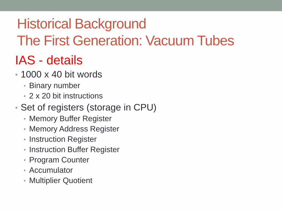
Historical Background
The First Generation: Vacuum Tubes
IAS - details • 1000 x 40 bit words
• Binary number
• 2 x 20 bit instructions
• Set of registers (storage in CPU) • Memory Buffer Register
• Memory Address Register
• Instruction Register
• Instruction Buffer Register
• Program Counter
• Accumulator
• Multiplier Quotient

Historical Background
The First Generation: Vacuum Tubes
Commercial Computers
• 1947 - Eckert-Mauchly Computer Corporation
• UNIVAC I (Universal Automatic Computer)
• US Bureau of Census 1950 calculations
• Became part of Sperry-Rand Corporation
• Late 1950s - UNIVAC II
• Faster
• More memory

Historical Background
The First Generation: Vacuum Tubes
IBM
• Punched-card processing equipment
• 1953 - the 701
• IBM’s first stored program computer
• Scientific calculations
• 1955 - the 702
• Business applications
• Lead to 700/7000 series

Historical Background
The Second Generation: Transistors • Replaced vacuum tubes
• Smaller
• Cheaper
• Less heat dissipation
• Solid State device
• Made from Silicon (Sand)
• Invented 1947 at Bell Labs
• William Shockley et al.

Historical Background
The Third Generation: Integrated Circuits Microelectronics
• Means: Literally - “small electronics”
• Tow fundamental types of components:
• 1- gates: is a device that implements a simple Boolean or logical
function, such as IF A AND B ARE TRUE
• THEN C IS TRUE
• 2- memory cells: is a device that can store one bit of
data
• By interconnecting large numbers of these fundamental
devices, we can construct a computer.
• These can be manufactured on a semiconductor. e.g. silicon
wafer

Historical Background
Later Generations • After third generation less general agreement on
defining generations of computers
• Later generations based on advances in integrated
circuit technology.
15

Summary: Generations of Computer
• Vacuum tube - 1946-1957
• Transistor - 1958-1964
• Small scale integration - 1965 on • Up to 100 devices on a chip
• Medium scale integration - to 1971 • 100-3,000 devices on a chip
• Large scale integration - 1971-1977 • 3,000 - 100,000 devices on a chip
• Very large scale integration - 1978 -1991 • 100,000 - 100,000,000 devices on a chip
• Ultra large scale integration – 1991 - • Over 100,000,000 devices on a chip

Components of a microcomputer system
• The Control Unit and the Arithmetic and Logic Unit
constitute the Central Processing Unit
• Data and instructions need to get into the system and
results out
• Input/output
• Temporary storage of code and results is needed
• Main memory

Computer Components: Top Level View

Memory Connection
• Receives and sends data
• Receives addresses (of locations)
• Receives control signals
• Read
• Write
• Timing

Memory Types
• Random Access Memory (RAM): allows data and
instructions to be accessed randomly from any
memory location (address). Primary storage.
• Volatile - lost when power is turned off
• Read Only Memory (ROM): usually contains
programs that help the computer system operate:
• can only be read: cannot be written to or altered by
the user (usually)
• ROM is not volatile
20
CPU Connection
• Reads instruction and data
• Writes out data (after processing)
• Sends control signals to other units
• Receives (& acts on) interrupts

Input/Output Connection(1)
• Similar to memory from computer’s viewpoint
• Output
• Receive data from computer
• Send data to peripheral
• Input
• Receive data from peripheral
• Send data to computer
Input/Output Connection(2)
• Receive control signals from computer
• Send control signals to peripherals
• e.g. spin disk
• Receive addresses from computer
• e.g. port number to identify peripheral
• Send interrupt signals (control)

Buses
• There are a number of possible interconnection systems
• Single and multiple BUS structures are most common
• e.g. Control/Address/Data bus (PC)
• e.g. Unibus (DEC-PDP)

What is a Bus?
• A communication pathway connecting two or more
devices
• Usually broadcast
• Often grouped
• A number of channels in one bus
• e.g. 32 bit data bus is 32 separate single bit channels
• Power lines may not be shown

Data Bus
• Carries data
• Remember that there is no difference between “data” and
“instruction” at this level
• Width is a key determinant of performance
• 8, 16, 32, 64 bit

Address bus
• Identify the source or destination of data
• e.g. CPU needs to read an instruction (data) from a given
location in memory
• Bus width determines maximum memory capacity of
system
• e.g. 8080 has 16 bit address bus giving 64k address space
Control Bus
• Control and timing information
• Memory read/write signal
• Interrupt request
• Clock signals

Bus Interconnection Scheme

Introduction to Microprocessor Explanation of Terms • An Address is a pattern of 0’s and 1 ’s that represents a specific
location in memory or a particular I/O device.
• Typical 8-bit microprocessors have 16 address lines
• These 16 lines can produce unique 16-bit patterns from
0000000000000000 to
11 11 1 1 11 1 11 11 11 1, representing 65,536 (2^16 =65,536)
different address combinations.
30

Introduction to Microprocessor Explanation of Terms
• Addressing mode is the manner in which the microprocessor
determines the operand (data) and destination addresses during
execution of an instruction.
• An Arithmetic-logic unit (ALU) is a digital circuit that performs
arithmetic and logic operations on two n-bit digital words.
• Bit is an abbreviation for the term binary digit. A binary digit can
have only two values, 0 and 1,
31
ALU

Introduction to Microprocessor Explanation of Terms
• Word size refers to the number of bits that can be processed
simultaneously by the basic
arithmetic circuits of a microprocessor.
A number of bits taken as a group in this
manner is called a word.
• For example, a 32-bit microprocessor can process a 32-bit word,
a 16-bit microprocessor can process a 16-bit word.
• 8086 is a 16-bit microprocessor can process a 16-bit word
32

Introduction to Microprocessor Explanation of Terms
• A bus consists of a number of conductors (wires) organized to
provide a means of
communication among different elements in a microprocessor
system.
• Cache Memory is a high-speed, directly accessible, relatively
small, semiconductor
read/write memory block used to store data/instructions that the
microprocessor may need in the immediate future.
33

Introduction to Microprocessor Explanation of Terms
• The instruction set of a microprocessor is a list of commands
that the microprocessor is designed to execute.
• Pipelining is a technique that overlaps instruction fetch
(instruction read) with execution.
34
S1 S2 S3 S4 S5
1
Cycle
s
Stages
S6
2
3
4
5
6
7
I-1
I-2 I-1
I-2 I-1
I-2 I-1
I-2 I-1
I-2 I-1
I-2

Microprocessor Data Types
• Fundamental Data Types:
• Bytes (8 bit)
• words (2 bytes)
• double words (4 bytes)
• Quad words (8 bytes)
35

Introduction To Microprocessors: Evolution of microprocessors:
Intel • 1971 - 4004
• First microprocessor
• All CPU components on a single chip
• 4 bit
• Followed in 1972 by 8008 • 8 bit
• Both designed for specific applications
• 1974 - 8080 • Intel’s first general purpose microprocessor

Introduction To Microprocessors:
New Approach – Multiple Cores
• Multiple processors on single chip
• Large shared cache
• Within a processor, increase in performance proportional
to square root of increase in complexity
• If software can use multiple processors, doubling number
of processors almost doubles performance
• So, use two simpler processors on the chip rather than
one more complex processor
• With two processors, larger caches are justified
• Power consumption of memory logic less than processing logic
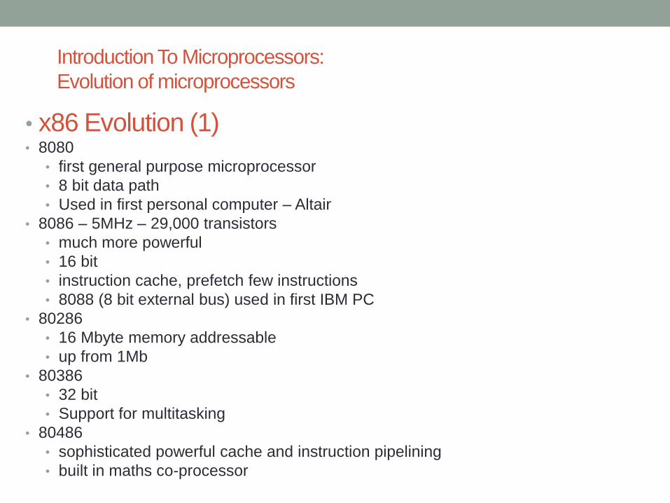
Introduction To Microprocessors:
Evolution of microprocessors
• x86 Evolution (1) • 8080
• first general purpose microprocessor
• 8 bit data path
• Used in first personal computer – Altair
• 8086 – 5MHz – 29,000 transistors
• much more powerful
• 16 bit
• instruction cache, prefetch few instructions
• 8088 (8 bit external bus) used in first IBM PC
• 80286
• 16 Mbyte memory addressable
• up from 1Mb
• 80386
• 32 bit
• Support for multitasking
• 80486
• sophisticated powerful cache and instruction pipelining
• built in maths co-processor

Introduction Microprocessors:
Evolution of microprocessors
• X86 Evolution (2) • Pentium
• Superscalar
• Multiple instructions executed in parallel
• Pentium Pro
• Increased superscalar organization
• Aggressive register renaming
• branch prediction
• data flow analysis
• speculative execution
• Pentium II
• MMX technology
• graphics, video & audio processing
• Pentium III
• Additional floating point instructions for 3D graphics

Introduction Microprocessors:
Evolution of microprocessors x86
Evolution (3) • Pentium 4
• Note Arabic rather than Roman numerals
• Further floating point and multimedia enhancements
• Core
• First x86 with dual core
• Core 2
• 64 bit architecture
• Core 2 Quad – 3GHz – 820 million transistors
• Four processors on chip

That’s all for Today!!
Text Book:
COMPUTER ORGANIZATION AND ARCHITECTURE
(Chapter 1.2.3)
41