Embed Size (px)
Citation preview
RS08Microcontrollers
freescale.com
DRM094Rev. 006/2007
Designer Reference Manual
Low-Cost Wireless Sensors
Low-Cost Wireless Sensors, Rev. 0
Freescale Semiconductor 3
Low-Cost Wireless SensorsDesigner Reference Manual
by: Oscar Luna GonzalezDaniel MorfinManuel DavalosSergio Garcia de AlbaRTAC Guadalajara
To provide the most up-to-date information, the revision of our documents on the World Wide Web will be the most current. Your printed copy may be an earlier revision. To verify that you have the latest information available, refer to http://www.freescale.com
The following revision history table summarizes changes contained in this document. For your convenience, the page number designators have been linked to the appropriate location.
Revision History
DateRevision
LevelDescription
PageNumber(s)
06/2007 0 Initial release 146

Revision History
Low-Cost Wireless Sensors, Rev. 0
4 Freescale Semiconductor
Low-Cost Wireless Sensors, Rev. 0
Freescale Semiconductor 1
Contents
Chapter 1 Introduction
1.1 Application Functionality . . . . . . . . . . . . . . . . . . . . . . . . . . . . . . . . . . . . . . . . . . . . . . . . . . . . . . . 51.2 Low-Cost Wireless Sensors Using a MC9RS08KA2 Reference Design Benefits . . . . . . . . . . . . 5
Chapter 2 Quick Start
2.1 Introduction . . . . . . . . . . . . . . . . . . . . . . . . . . . . . . . . . . . . . . . . . . . . . . . . . . . . . . . . . . . . . . . . . 72.2 System Requirements . . . . . . . . . . . . . . . . . . . . . . . . . . . . . . . . . . . . . . . . . . . . . . . . . . . . . . . . . 72.3 Low-Cost Wireless Sensors Setup . . . . . . . . . . . . . . . . . . . . . . . . . . . . . . . . . . . . . . . . . . . . . . . 7
Chapter 3 Hardware Description
3.1 Introduction . . . . . . . . . . . . . . . . . . . . . . . . . . . . . . . . . . . . . . . . . . . . . . . . . . . . . . . . . . . . . . . . 133.2 Technical Data . . . . . . . . . . . . . . . . . . . . . . . . . . . . . . . . . . . . . . . . . . . . . . . . . . . . . . . . . . . . . . 163.2.1 Operating Environment . . . . . . . . . . . . . . . . . . . . . . . . . . . . . . . . . . . . . . . . . . . . . . . . . . . . 163.2.2 MC9RS08KA2 Microcontroller . . . . . . . . . . . . . . . . . . . . . . . . . . . . . . . . . . . . . . . . . . . . . . . 163.2.2.1 Features . . . . . . . . . . . . . . . . . . . . . . . . . . . . . . . . . . . . . . . . . . . . . . . . . . . . . . . . . . . . . . 163.2.3 MC33493 RF Transmitter. . . . . . . . . . . . . . . . . . . . . . . . . . . . . . . . . . . . . . . . . . . . . . . . . . . 163.2.4 MMA6261Q Acceleration Sensor. . . . . . . . . . . . . . . . . . . . . . . . . . . . . . . . . . . . . . . . . . . . . 173.2.5 MPXM2010GS Compesated Pressure Sensor . . . . . . . . . . . . . . . . . . . . . . . . . . . . . . . . . . 173.3 Low-Cost Wireless Sensors Using an MC9RS08KA2 Functionality . . . . . . . . . . . . . . . . . . . . . 183.3.1 Low-Cost Wireless Sensors Using an MC9RS08KA2 Architecture . . . . . . . . . . . . . . . . . . . 183.3.2 Power Supply . . . . . . . . . . . . . . . . . . . . . . . . . . . . . . . . . . . . . . . . . . . . . . . . . . . . . . . . . . . . 183.3.3 MC9RS08KA2 Processing Unit . . . . . . . . . . . . . . . . . . . . . . . . . . . . . . . . . . . . . . . . . . . . . . 183.3.4 Sensor Block . . . . . . . . . . . . . . . . . . . . . . . . . . . . . . . . . . . . . . . . . . . . . . . . . . . . . . . . . . . . 203.3.4.1 Acceleration Module . . . . . . . . . . . . . . . . . . . . . . . . . . . . . . . . . . . . . . . . . . . . . . . . . . . . . 203.3.4.2 Lighting Module . . . . . . . . . . . . . . . . . . . . . . . . . . . . . . . . . . . . . . . . . . . . . . . . . . . . . . . . 213.3.4.3 Temperature Module . . . . . . . . . . . . . . . . . . . . . . . . . . . . . . . . . . . . . . . . . . . . . . . . . . . . 213.3.4.4 Pressure Module . . . . . . . . . . . . . . . . . . . . . . . . . . . . . . . . . . . . . . . . . . . . . . . . . . . . . . . 223.3.4.5 Ultrasound Module . . . . . . . . . . . . . . . . . . . . . . . . . . . . . . . . . . . . . . . . . . . . . . . . . . . . . . 233.3.5 Tango MC33493 Transmitter Block . . . . . . . . . . . . . . . . . . . . . . . . . . . . . . . . . . . . . . . . . . . 243.3.6 Antenna . . . . . . . . . . . . . . . . . . . . . . . . . . . . . . . . . . . . . . . . . . . . . . . . . . . . . . . . . . . . . . . . 263.3.6.1 RF Section . . . . . . . . . . . . . . . . . . . . . . . . . . . . . . . . . . . . . . . . . . . . . . . . . . . . . . . . . . . . 263.4 Board Layout . . . . . . . . . . . . . . . . . . . . . . . . . . . . . . . . . . . . . . . . . . . . . . . . . . . . . . . . . . . . . . . 313.4.1 Low-cost Wireless Sensors Using a MC9RS08KA2 board layout . . . . . . . . . . . . . . . . . . . . 323.4.1.1 Acceleration Module Board Component Side. . . . . . . . . . . . . . . . . . . . . . . . . . . . . . . . . . 323.4.1.2 Lighting Module Board Component Side . . . . . . . . . . . . . . . . . . . . . . . . . . . . . . . . . . . . . 323.4.1.3 Pressure Module Board Component Side . . . . . . . . . . . . . . . . . . . . . . . . . . . . . . . . . . . . 333.4.1.4 Temperature Module Board Component Side . . . . . . . . . . . . . . . . . . . . . . . . . . . . . . . . . 33
Low-Cost Wireless Sensors, Rev. 0
2 Freescale Semiconductor
3.4.1.5 Ultrasound Module Board Component Side . . . . . . . . . . . . . . . . . . . . . . . . . . . . . . . . . . . 343.4.2 General Layout Explanation. . . . . . . . . . . . . . . . . . . . . . . . . . . . . . . . . . . . . . . . . . . . . . . . . 343.4.3 . . . . . . . . . . . . . . . . . . . . . . . . . . . . . . . . . . . . . . . . . . . . . . . . . . . . . . . . . . . . PCB Features353.4.3.1 . . . . . . . . . . . . . . . . . . . . . . . . . . . . . . . . . . . . . . . . . . . . . . . . . . . . . . . . . . . . .Board Size353.4.3.2 Two Layers . . . . . . . . . . . . . . . . . . . . . . . . . . . . . . . . . . . . . . . . . . . . . . . . . . . . . . . . . . . . 353.4.3.3 Board Material FR-4 . . . . . . . . . . . . . . . . . . . . . . . . . . . . . . . . . . . . . . . . . . . . . . . . . . . . . 353.4.3.4 . . . . . . . . . . . . . . . . . . . . . . . . . . . Minimum Circuit Board Trace Width for Signal Traces353.4.4 Component Placement. . . . . . . . . . . . . . . . . . . . . . . . . . . . . . . . . . . . . . . . . . . . . . . . . . . . . 353.4.4.1 Sensor block. . . . . . . . . . . . . . . . . . . . . . . . . . . . . . . . . . . . . . . . . . . . . . . . . . . . . . . . . . . 383.4.4.2 . . . . . . . . . . . . . . . . . . . . . . . . . . . . . . . . . . . . . . . . . . . . . . . . . . . . . . . Transmitter Block383.4.4.3 BDM Connector . . . . . . . . . . . . . . . . . . . . . . . . . . . . . . . . . . . . . . . . . . . . . . . . . . . . . . . . 393.4.4.4 Processing Unit Block. . . . . . . . . . . . . . . . . . . . . . . . . . . . . . . . . . . . . . . . . . . . . . . . . . . . 393.4.4.5 . . . . . . . . . . . . . . . . . . . . . . . . . . . . . . . . . . . . . . . . . . . . . . . . . . MC9RS08KA2 Footprint393.4.4.6 Accelerometer Footprint . . . . . . . . . . . . . . . . . . . . . . . . . . . . . . . . . . . . . . . . . . . . . . . . . . 403.4.4.7 . . . . . . . . . . . . . . . . . . . . . . . . . . . . . . . . . . . . . . . . . . . . . . . . . . . . . . . . . Via dimensions403.4.5 Layout Layers. . . . . . . . . . . . . . . . . . . . . . . . . . . . . . . . . . . . . . . . . . . . . . . . . . . . . . . . . . . . 403.4.5.1 Layers Stackup. . . . . . . . . . . . . . . . . . . . . . . . . . . . . . . . . . . . . . . . . . . . . . . . . . . . . . . . . 403.4.5.2 Top Layer . . . . . . . . . . . . . . . . . . . . . . . . . . . . . . . . . . . . . . . . . . . . . . . . . . . . . . . . . . . . . 413.4.5.3 Bottom Layer . . . . . . . . . . . . . . . . . . . . . . . . . . . . . . . . . . . . . . . . . . . . . . . . . . . . . . . . . . 44
Chapter 4 Firmware Description
4.1 Introduction . . . . . . . . . . . . . . . . . . . . . . . . . . . . . . . . . . . . . . . . . . . . . . . . . . . . . . . . . . . . . . . . 474.1.1 Firmware Basics. . . . . . . . . . . . . . . . . . . . . . . . . . . . . . . . . . . . . . . . . . . . . . . . . . . . . . . . . . 474.1.2 . . . . . . . . . . . . . . . . . . . . . . . . . . . . . . . . . . . . . . . . . . . . . . . . . . . . . . . . . Application Basics474.2 . . . . . . . . . . . . . . . . . . . . . . . . . . . . . . . . . . . . . . . . . . . . . . . . . . . . . . . . . . . Project Introduction474.2.1 Coding Conventions. . . . . . . . . . . . . . . . . . . . . . . . . . . . . . . . . . . . . . . . . . . . . . . . . . . . . . . 474.2.2 . . . . . . . . . . . . . . . . . . . . . . . . . . . . . . . . . . . . . . . . . . . . . . . . . . . . . . . . . . . . . Project Files474.2.3 . . . . . . . . . . . . . . . . . . . . . . . . . . . . . . . . . . . . . . . . . . . . . . . Implemented MCU Peripherals484.2.3.1 . . . . . . . . . . . . . . . . . . . . . . . . . . . . . . . . . . . . . . . . . . . . . . . . . . . Implemented Interrupts494.2.3.2 Main Variables of Drivers . . . . . . . . . . . . . . . . . . . . . . . . . . . . . . . . . . . . . . . . . . . . . . . . . 494.2.3.3 Memory Usage . . . . . . . . . . . . . . . . . . . . . . . . . . . . . . . . . . . . . . . . . . . . . . . . . . . . . . . . . 494.3 Firmware Implementation . . . . . . . . . . . . . . . . . . . . . . . . . . . . . . . . . . . . . . . . . . . . . . . . . . . . . 504.3.1 . . . . . . . . . . . . . . . . . . . . . . . . . . . . . . . . . . . . . . . . . . . . . . . . . . . . . Drivers Implementation504.3.1.1 . . . . . . . . . . . . . . . . . . . . . . . . . . . . . . . . . . . . . . . . . . . . . . Tango RF Transmitter Driver504.3.1.2 . . . . . . . . . . . . . . . . . . . . . . . . . . . . . . . . . . . Reduce Encrypt TEAMAC Algorithm Driver514.3.1.3 ADC Driver . . . . . . . . . . . . . . . . . . . . . . . . . . . . . . . . . . . . . . . . . . . . . . . . . . . . . . . . . . . . 544.3.2 . . . . . . . . . . . . . . . . . . . . . . . . . . . . . . . . . . . . . . . . . . . . . . . . . . . . . . .Sensors Applications564.3.2.1 Accelerometer - Object Position Detection. . . . . . . . . . . . . . . . . . . . . . . . . . . . . . . . . . . . 564.3.2.2 . . . . . . . . . . . . . . . . . . . . . . . . . . . . . . . . . . . . . . . . . . . . . . . . . . . . . . . . . . . Temperature574.3.2.3 . . . . . . . . . . . . . . . . . . . . . . . . . . . . . . . . . . . . . . . . . . . . .Ultrasonic - Distance Measurer604.3.2.4 Pressure . . . . . . . . . . . . . . . . . . . . . . . . . . . . . . . . . . . . . . . . . . . . . . . . . . . . . . . . . . . . . . 624.3.2.5 . . . . . . . . . . . . . . . . . . . . . . . . . . . . . . . . . . . . . . . . . . . . . . . . . . . . . . . . . . . . . . . . . Light634.3.2.6 Push-button . . . . . . . . . . . . . . . . . . . . . . . . . . . . . . . . . . . . . . . . . . . . . . . . . . . . . . . . . . . 654.4 Programming LCWi boards and DEMO908AP64 . . . . . . . . . . . . . . . . . . . . . . . . . . . . . . . . . . . 664.4.1 Programming LCWi boards . . . . . . . . . . . . . . . . . . . . . . . . . . . . . . . . . . . . . . . . . . . . . . . . . 674.4.1.1 Programming the Firmware . . . . . . . . . . . . . . . . . . . . . . . . . . . . . . . . . . . . . . . . . . . . . . . 674.4.1.2 Using the Firmware . . . . . . . . . . . . . . . . . . . . . . . . . . . . . . . . . . . . . . . . . . . . . . . . . . . . . 67
Low-Cost Wireless Sensors, Rev. 0
Freescale Semiconductor 3
4.4.2 Programming DEMO908AP64 . . . . . . . . . . . . . . . . . . . . . . . . . . . . . . . . . . . . . . . . . . . . . . . 674.4.2.1 Programming the Firmware . . . . . . . . . . . . . . . . . . . . . . . . . . . . . . . . . . . . . . . . . . . . . . . 674.4.3 Setting the Romeo RF Receiver . . . . . . . . . . . . . . . . . . . . . . . . . . . . . . . . . . . . . . . . . . . . . 68
Chapter 5 Graphical User Interface
5.1 Introduction . . . . . . . . . . . . . . . . . . . . . . . . . . . . . . . . . . . . . . . . . . . . . . . . . . . . . . . . . . . . . . . . 695.2 Wireless Demo Application Graphical User Interface . . . . . . . . . . . . . . . . . . . . . . . . . . . . . . . . 705.2.1 Port Configuration . . . . . . . . . . . . . . . . . . . . . . . . . . . . . . . . . . . . . . . . . . . . . . . . . . . . . . . . 705.2.2 Sensor Id Configuration . . . . . . . . . . . . . . . . . . . . . . . . . . . . . . . . . . . . . . . . . . . . . . . . . . . . 715.2.3 Show Graphics. . . . . . . . . . . . . . . . . . . . . . . . . . . . . . . . . . . . . . . . . . . . . . . . . . . . . . . . . . . 735.2.4 Sensor Viewer . . . . . . . . . . . . . . . . . . . . . . . . . . . . . . . . . . . . . . . . . . . . . . . . . . . . . . . . . . . 755.3 LCWi Modules View in Graphical User Interface . . . . . . . . . . . . . . . . . . . . . . . . . . . . . . . . . . . . 755.3.1 Temperature. . . . . . . . . . . . . . . . . . . . . . . . . . . . . . . . . . . . . . . . . . . . . . . . . . . . . . . . . . . . . 755.3.2 Acceleration Sensor . . . . . . . . . . . . . . . . . . . . . . . . . . . . . . . . . . . . . . . . . . . . . . . . . . . . . . . 765.3.3 Push-button . . . . . . . . . . . . . . . . . . . . . . . . . . . . . . . . . . . . . . . . . . . . . . . . . . . . . . . . . . . . . 775.3.4 PhotoResistor. . . . . . . . . . . . . . . . . . . . . . . . . . . . . . . . . . . . . . . . . . . . . . . . . . . . . . . . . . . . 785.3.5 Pressure Sensor . . . . . . . . . . . . . . . . . . . . . . . . . . . . . . . . . . . . . . . . . . . . . . . . . . . . . . . . . 785.3.6 Ultrasonic Sensor. . . . . . . . . . . . . . . . . . . . . . . . . . . . . . . . . . . . . . . . . . . . . . . . . . . . . . . . . 79
Appendix A. BOM and Schematics
A.1 BOM. . . . . . . . . . . . . . . . . . . . . . . . . . . . . . . . . . . . . . . . . . . . . . . . . . . . . . . . . . . . . . . . . . . . . . 835.4 Schematics . . . . . . . . . . . . . . . . . . . . . . . . . . . . . . . . . . . . . . . . . . . . . . . . . . . . . . . . . . . . . . . . 88
Appendix B. Firmware
B.1 Drivers . . . . . . . . . . . . . . . . . . . . . . . . . . . . . . . . . . . . . . . . . . . . . . . . . . . . . . . . . . . . . . . . . . . . 99B.1.1 Tango Driver . . . . . . . . . . . . . . . . . . . . . . . . . . . . . . . . . . . . . . . . . . . . . . . . . . . . . . . . . . . . . 99B.1.2 Reduce Encrypt Teamac Algorithm. . . . . . . . . . . . . . . . . . . . . . . . . . . . . . . . . . . . . . . . . . . 104B.1.3 ADC Driver . . . . . . . . . . . . . . . . . . . . . . . . . . . . . . . . . . . . . . . . . . . . . . . . . . . . . . . . . . . . . 110B.2 APPLICATIONS. . . . . . . . . . . . . . . . . . . . . . . . . . . . . . . . . . . . . . . . . . . . . . . . . . . . . . . . . . . . 112B.2.1 Accelerometer . . . . . . . . . . . . . . . . . . . . . . . . . . . . . . . . . . . . . . . . . . . . . . . . . . . . . . . . . . . 112B.2.2 Temperature . . . . . . . . . . . . . . . . . . . . . . . . . . . . . . . . . . . . . . . . . . . . . . . . . . . . . . . . . . . . 116B.2.3 Ultrasonic Distance Measure . . . . . . . . . . . . . . . . . . . . . . . . . . . . . . . . . . . . . . . . . . . . . . . 120B.2.4 Pressure . . . . . . . . . . . . . . . . . . . . . . . . . . . . . . . . . . . . . . . . . . . . . . . . . . . . . . . . . . . . . . . 126B.2.5 Light. . . . . . . . . . . . . . . . . . . . . . . . . . . . . . . . . . . . . . . . . . . . . . . . . . . . . . . . . . . . . . . . . . . 130B.2.6 Push Button. . . . . . . . . . . . . . . . . . . . . . . . . . . . . . . . . . . . . . . . . . . . . . . . . . . . . . . . . . . . . 134B.2.7 Romeo RF Receiver . . . . . . . . . . . . . . . . . . . . . . . . . . . . . . . . . . . . . . . . . . . . . . . . . . . . . . 136

Low-Cost Wireless Sensors, Rev. 0
4 Freescale Semiconductor

Low-Cost Wireless Sensors, Rev. 0
Freescale Semiconductor 5
Chapter 1 Introduction
1.1 Application Functionality
The Low-Cost Wireless Sensors using a MC9RS08KA2 reference design provides a solution for interfacing different sensor modules, via radio frequency (RF) to a base station which is connected to a computer. The output of the different sensor modules is monitored by a graphical user interface (GUI).
Every module contains a Tango RF transmitter (MC33943) and a RS08 family 8-bit ultra low-cost microcontroller unit (MCU) (6-pin MC9RS08KA2). The pressure and acceleration applications have also an accelerometer sensor (MMA6261Q) and a pressure sensor (MPXM2102G).
This reference design demonstrates that Freescale’s cost-effective solution enables to implement a diverse sensor network. A multi-faceted sensor network can be implemented by using only an MCU, sensors, and RF products.
1.2 Low-Cost Wireless Sensors Using a MC9RS08KA2 Reference Design Benefits
The benefits are:• Only one pin of the MC9RS98KA2 transmits the data, enables transmission and the powering on
the accelerometer and the pressure sensor.• Low cost due to the price of most components.• Low power consumption by disabling the Tango when not transmitting. Accelerometer and
pressure sensors are also disabled during non-transmission times.• Safeguards information sent by the Tango with encryption.• Five sensor modules: acceleration, lighting, pressure, temperature, ultrasound and push-button.• Real time measures presented in an intuitive GUI.• The push-button module can be used as a remote control.• The ultrasound module board size is 1.75 in x 1.8 in.• The rest of the board size is 1.014 in x 1.8 in.• The range is up to 15 m.

Introduction
Low-Cost Wireless Sensors, Rev. 0
6 Freescale Semiconductor
Low-Cost Wireless Sensors, Rev. 0
Freescale Semiconductor 7
Chapter 2 Quick Start
2.1 Introduction
This section describes how to set up and start the Low-Cost Wireless Sensors (LCWi) demo boards. The reference design shows the basic and advanced functionalities of the LCWi.
2.2 System Requirements
The application software is in the MCUs flash memory, if necessary the original software is located at www.freescale.com.
To interface the Romeo with the computer, a serial cable is needed. And the power supply voltage required is 9 V. Use HyperTerminal or the GUI supplied with this DRM to see the data transmitted by the LCWi boads.
The power supply voltage required by the Tango is 3 V.
The LCWi transmitters can operate on a CR 1/3N 3 V Lithium cell, or be powered by the background debugging mode (BDM) connector.
2.3 Low-Cost Wireless Sensors Setup
The LCWi requires minimal set up. The modules are distributed with the application in flash memory and all jumpers in default position. Table 2-1 describes the jumpers default position.
NOTEThe pressure module does not include a pushbutton and therefore J3 is not in the board.
Table 2-1. Function and Default Positions for Module Jumpers
Jumper Default position Function
J2 Not connected
Connected: data/enable circuit closed. Allows transmission of data and enables transmission for the
Tango.Not connected: data/enable circuit open. Used for debugging. Can program board without applying
voltage to the data pin of the Tango.
J3 Connected
Connected: enables the use of the pushbutton if available on the board.
Not connected: disables the pushbutton to avoid shorts to ground during programming. See note.
J4 SolderedFunctions as a permanent connection for the
data/enable circuit of the Tango. Can be placed after final debugging, replacing J2.
Quick Start
Low-Cost Wireless Sensors, Rev. 0
8 Freescale Semiconductor
Table 2-2 describes the positions and functions of the jumpers for the ultrasound module.Table 2-2. Function and Default Positions for Module Jumpers in Ultrasound Module
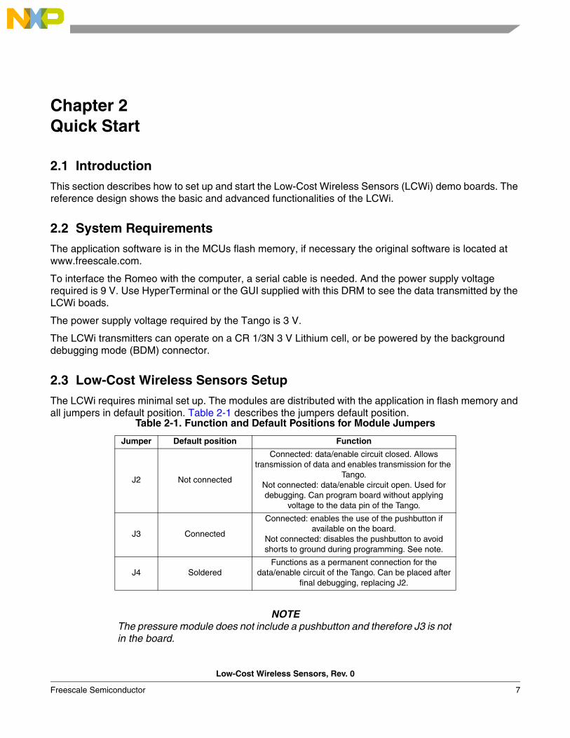
Figure 2-1 through Figure 2-5 show the pictures of the LCWi boards that showcase the most important parts of the modules.
Figure 2-1. Low-cost Wireless Sensors Using a MC9RS08KA2 Board Acceleration Module (Front)
Jumper Default position Function
J2 Not connected
Connected: data/enable circuit closed. Allows transmission of data and enables transmission for the
Tango.Not connected: data/enable circuit open. Used for debugging. Can program board without applying
voltage to the data pin of the Tango.
J3 ConnectedFunctions as a permament connection for the
data/enable circuit of the Tango. Can be placed after final debugging, replacing J2.
Low-Cost Wireless Sensors Setup
Low-Cost Wireless Sensors, Rev. 0
Freescale Semiconductor 9
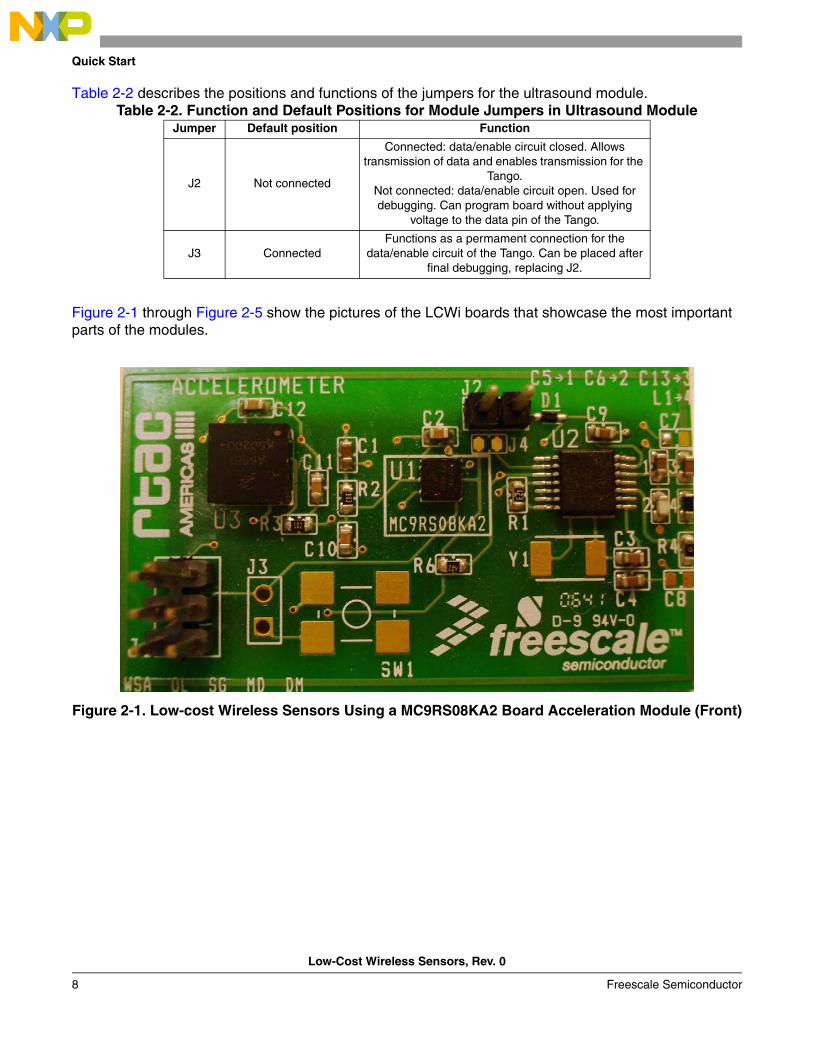
Figure 2-2. Low-cost Wireless Sensors Using a MC9RS08KA2 Board Lighting Module (Front)
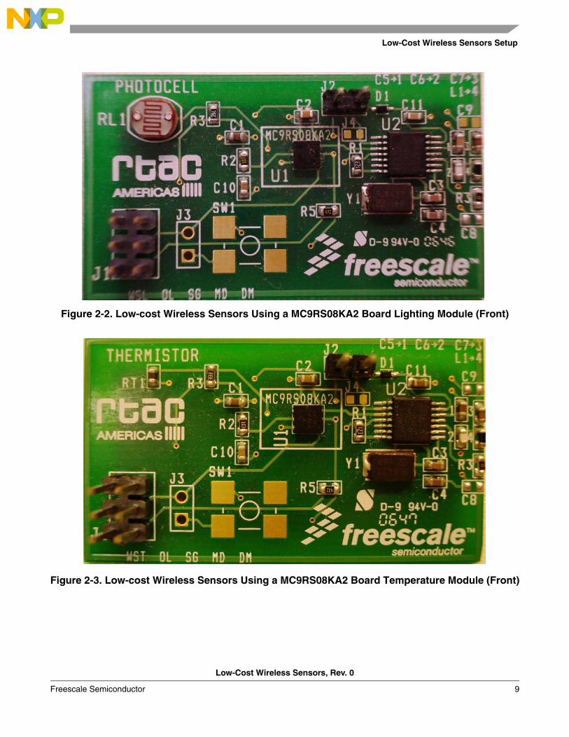
Figure 2-3. Low-cost Wireless Sensors Using a MC9RS08KA2 Board Temperature Module (Front)
Quick Start
Low-Cost Wireless Sensors, Rev. 0
10 Freescale Semiconductor
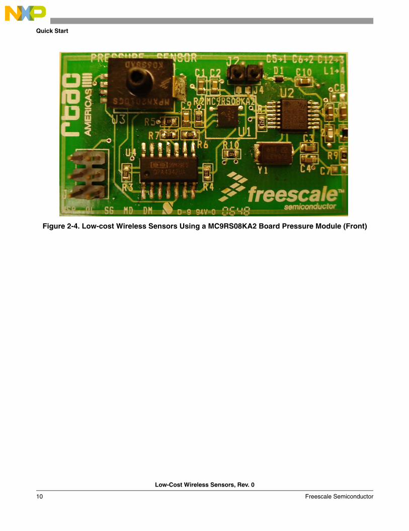
Figure 2-4. Low-cost Wireless Sensors Using a MC9RS08KA2 Board Pressure Module (Front)
Low-Cost Wireless Sensors Setup
Low-Cost Wireless Sensors, Rev. 0
Freescale Semiconductor 11
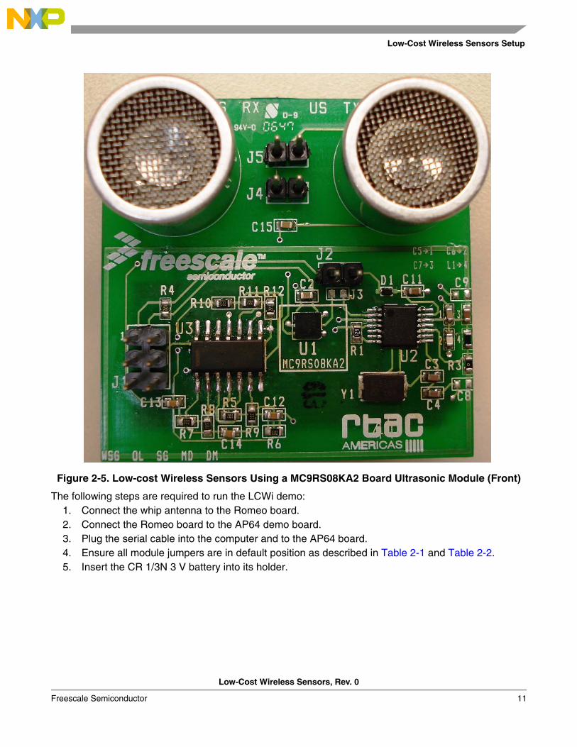
Figure 2-5. Low-cost Wireless Sensors Using a MC9RS08KA2 Board Ultrasonic Module (Front)
The following steps are required to run the LCWi demo:1. Connect the whip antenna to the Romeo board.2. Connect the Romeo board to the AP64 demo board.3. Plug the serial cable into the computer and to the AP64 board.4. Ensure all module jumpers are in default position as described in Table 2-1 and Table 2-2.5. Insert the CR 1/3N 3 V battery into its holder.

Quick Start
Low-Cost Wireless Sensors, Rev. 0
12 Freescale Semiconductor
Low-Cost Wireless Sensors, Rev. 0
Freescale Semiconductor 13
Chapter 3 Hardware Description
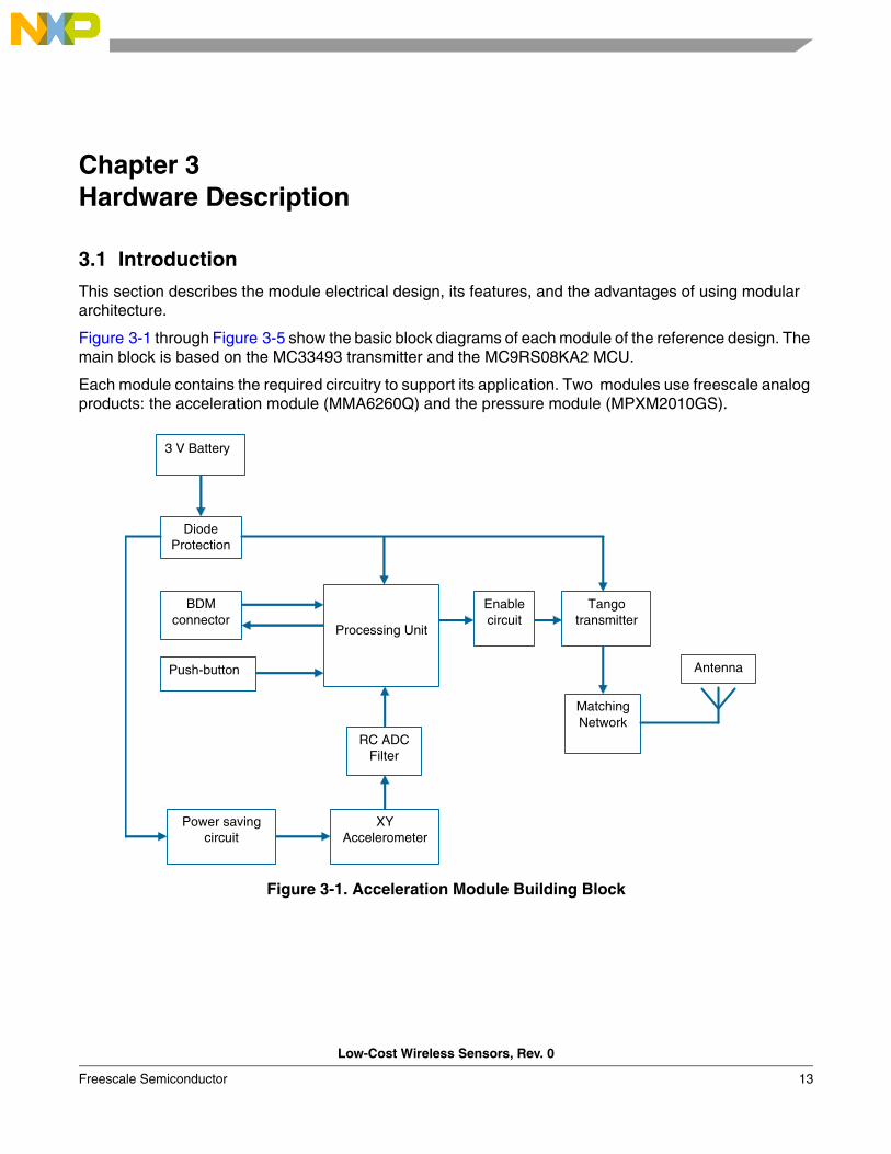
3.1 Introduction
This section describes the module electrical design, its features, and the advantages of using modular architecture.
Figure 3-1 through Figure 3-5 show the basic block diagrams of each module of the reference design. The main block is based on the MC33493 transmitter and the MC9RS08KA2 MCU.
Each module contains the required circuitry to support its application. Two modules use freescale analog products: the acceleration module (MMA6260Q) and the pressure module (MPXM2010GS).
Figure 3-1. Acceleration Module Building Block
Diode Protection
3 V Battery
Tango transmitter
BDM connector
Push-button Antenna
Matching Network
XY Accelerometer
RC ADC Filter
Enable circuit
Processing Unit
Power saving circuit
Hardware Description
Low-Cost Wireless Sensors, Rev. 0
14 Freescale Semiconductor
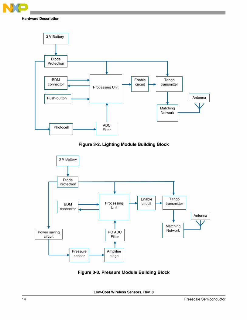
Figure 3-2. Lighting Module Building Block
Figure 3-3. Pressure Module Building Block
Diode Protection
3 V Battery
Tango transmitter
BDM connector
Push-button Antenna
Matching Network
ADC Filter
Enable circuit
Processing Unit
Photocell
Diode Protection
3 V Battery
Tango transmitter BDM
connector
Antenna
Matching Network
Pressure sensor
RC ADC Filter
Enable circuit Processing
Unit
Power saving circuit
Amplifier stage
Introduction
Low-Cost Wireless Sensors, Rev. 0
Freescale Semiconductor 15
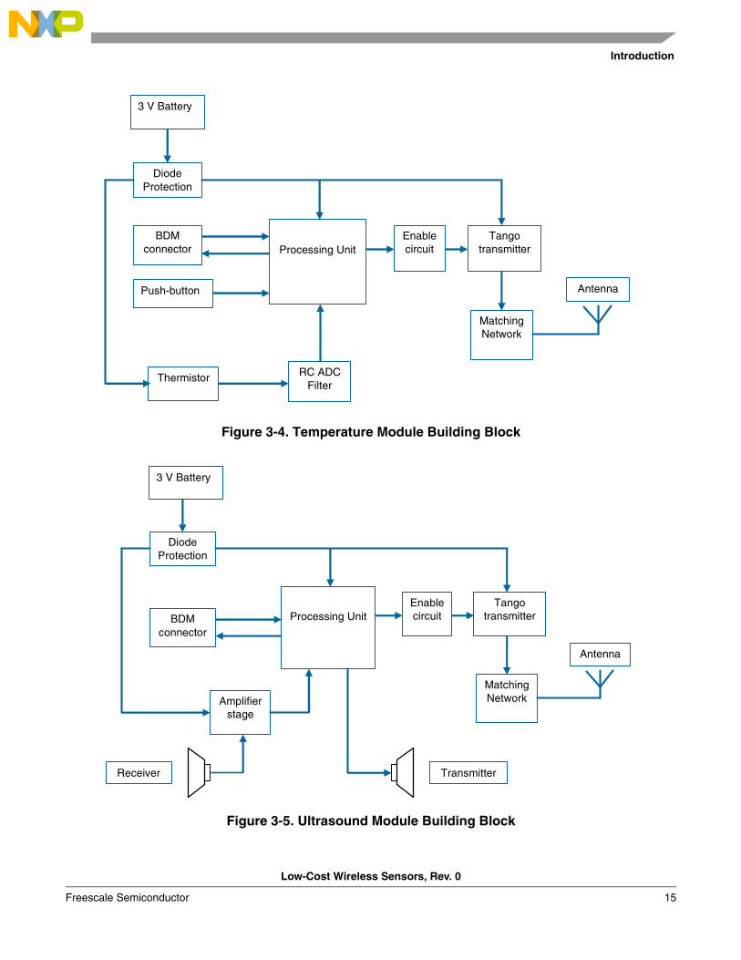
Figure 3-4. Temperature Module Building Block
Figure 3-5. Ultrasound Module Building Block
Diode Protection
3 V Battery
Tango transmitter
BDM connector
Push-button Antenna
Matching Network
RC ADC Filter
Enable circuit Processing Unit
Thermistor
Diode Protection
3 V Battery
Tango transmitter BDM
connector
Antenna
Matching Network
Enable circuit Processing Unit
Amplifier stage
Transmitter Receiver

Hardware Description
Low-Cost Wireless Sensors, Rev. 0
16 Freescale Semiconductor
3.2 Technical Data
This section provides technical detail on some of the main components used in this reference design.
3.2.1 Operating Environment• Ambient Temperature: -40°C to 85°C• Battery Voltage Range: 3 V to 3.6 V• Reverse Voltage: 30 V
3.2.2 MC9RS08KA2 Microcontroller
The control unit is the MC9RS08KA2, which has an RS08 reduced core and various peripheral modules. It is also a member of the Freescale Controller Continuum, featured as the ultra low cost, low-end MCU.
3.2.2.1 Features• Contains 8-bit RS08 core
– Up to 10 MHz (bus frequency) at 1.8 V for 100 ns minimum instruction time.– RS08 instruction set.– Supports tiny/short address mode.– 14-byte fast-access RAM.– Allows emulation of HC08/HCS08 zero-offset index addressing mode instructions.
• Third-Generation Flash and RAM, extremely fast byte writable programming– 63 B RAM – 2 KB Flash (1 KB Flash available)
• Flexible Clock Options• 4 Bidirectional I/O lines with software selectable pull-up, eliminates need for external resistors.• Analog Comparator• Real Time Interrupt • 8-bit timer with 8-bit prescale• System Protection
– Resets an instance of runaways or corrupted code.– Low Voltage Detection.– Illegal Opcode and illegal address detection.– Flash security feature.
• Single wire debugging and emulation interface; eliminates need for expensive emulation tools or development hardware.
3.2.3 MC33493 RF Transmitter
The MC33493 is the main part of the transmitter block in all the LCWi modules. It is a phase locked loop (PLL) tuned, and low power ultra high frequency (UHF) transmitter. The modes of operation can be controlled through several digital input pins. The power supply voltage ranges from 1.9 V to 3.7 V allowing operation from one lithium cell.
MC33493 RF Transmitter features:• Switchable frequency bands 315-434 MHz and 868 MHz.• On-off keying (OOK) and frequency shift keying (FSK) modulation.• Adjustable output power range.• Fully integrated voltage controlled oscillator (VCO).
Technical Data
Low-Cost Wireless Sensors, Rev. 0
Freescale Semiconductor 17
• Supply voltage range: 1.9 V - 3.7 V.• Very low standby current: 0.1 nA @ T A = 25°C.• Low supply voltage shutdown.• Data clock output for microcontroller.• Extended temperature range: -40°C to 125°C.• Low external component count.• Typical application compliant with the European telecommunication standards institute (ETSI).
The transmitter can be found on a thin-shrink small outline package (TSSOP) 14 pin package, 4.4*5.1.0P0.65.
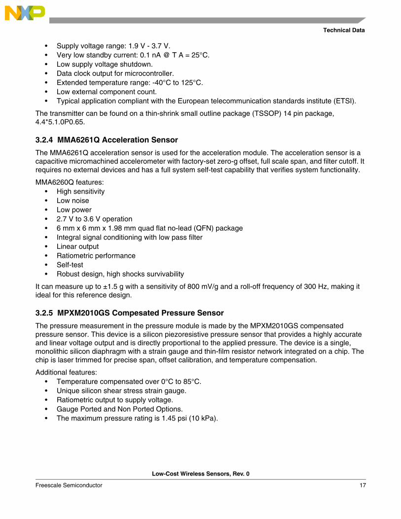
3.2.4 MMA6261Q Acceleration Sensor
The MMA6261Q acceleration sensor is used for the acceleration module. The acceleration sensor is a capacitive micromachined accelerometer with factory-set zero-g offset, full scale span, and filter cutoff. It requires no external devices and has a full system self-test capability that verifies system functionality.
MMA6260Q features:• High sensitivity• Low noise• Low power• 2.7 V to 3.6 V operation• 6 mm x 6 mm x 1.98 mm quad flat no-lead (QFN) package• Integral signal conditioning with low pass filter• Linear output• Ratiometric performance• Self-test• Robust design, high shocks survivability
It can measure up to ±1.5 g with a sensitivity of 800 mV/g and a roll-off frequency of 300 Hz, making it ideal for this reference design.
3.2.5 MPXM2010GS Compesated Pressure Sensor
The pressure measurement in the pressure module is made by the MPXM2010GS compensated pressure sensor. This device is a silicon piezoresistive pressure sensor that provides a highly accurate and linear voltage output and is directly proportional to the applied pressure. The device is a single, monolithic silicon diaphragm with a strain gauge and thin-film resistor network integrated on a chip. The chip is laser trimmed for precise span, offset calibration, and temperature compensation.
Additional features:• Temperature compensated over 0°C to 85°C.• Unique silicon shear stress strain gauge.• Ratiometric output to supply voltage.• Gauge Ported and Non Ported Options.• The maximum pressure rating is 1.45 psi (10 kPa).

Hardware Description
Low-Cost Wireless Sensors, Rev. 0
18 Freescale Semiconductor
3.3 Low-Cost Wireless Sensors Using an MC9RS08KA2 Functionality
This reference design is intended for the commercial markets in measuring applications. Other modules based on this reference design can be created to satisfy the user needs.
3.3.1 Low-Cost Wireless Sensors Using an MC9RS08KA2 Architecture
Schematics for the modules are provided in Appendix A. Figure 3-6 to Figure 3-9 show the building block diagrams.
By using the MCU’s resources, the LCWi can handle the data transmission, enabling encryption, sensing, and power control.
The modules can be divided into these basic blocks:• Power supply• Processing unit• Sensor block• Transmitter block• Antenna
3.3.2 Power Supply
The power supply is a 3 V CR 1/3N lithium cell. To protect against an incorrect polarized battery placement a Schottky barrier diode is used. It has a 30 V reverse voltage and a forward voltage of 0.35 V at 10 mA forward current.
Capacitor C1 is used for decoupling and to avoid spikes and ripples in the battery output voltage.
Figure 3-6. Power Supply
3.3.3 MC9RS08KA2 Processing Unit
The processing units for the acceleration, lighting, and temperature modules are similar.
Jumper J3 is used to disconnect the push-button from grounding the programming voltage pin Vpp.
Low-Cost Wireless Sensors Using an MC9RS08KA2 Functionality
Low-Cost Wireless Sensors, Rev. 0
Freescale Semiconductor 19
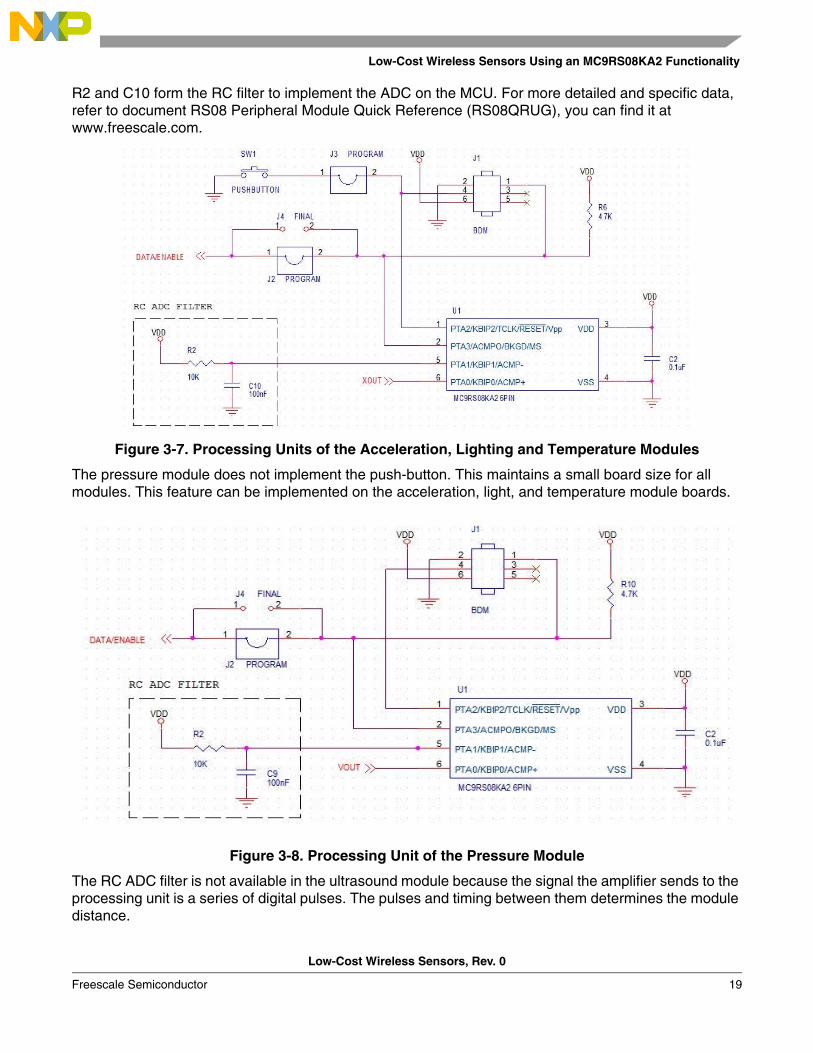
R2 and C10 form the RC filter to implement the ADC on the MCU. For more detailed and specific data, refer to document RS08 Peripheral Module Quick Reference (RS08QRUG), you can find it at www.freescale.com.
Figure 3-7. Processing Units of the Acceleration, Lighting and Temperature Modules
The pressure module does not implement the push-button. This maintains a small board size for all modules. This feature can be implemented on the acceleration, light, and temperature module boards.
Figure 3-8. Processing Unit of the Pressure Module
The RC ADC filter is not available in the ultrasound module because the signal the amplifier sends to the processing unit is a series of digital pulses. The pulses and timing between them determines the module distance.
Hardware Description
Low-Cost Wireless Sensors, Rev. 0
20 Freescale Semiconductor
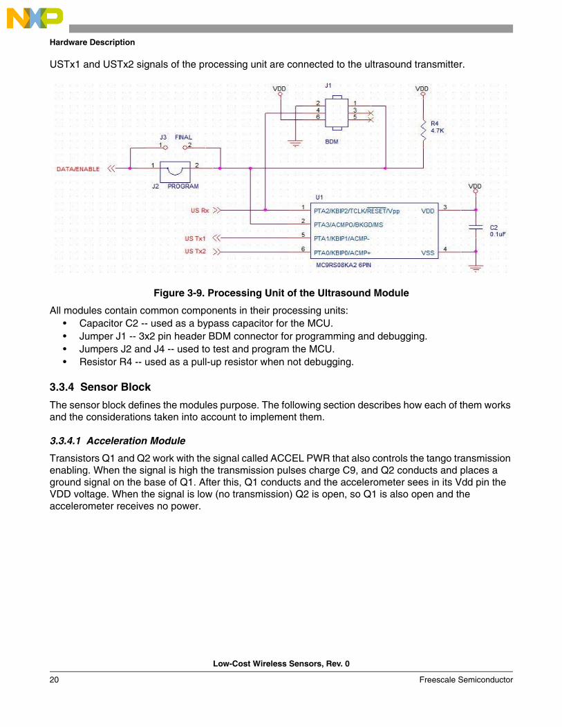
USTx1 and USTx2 signals of the processing unit are connected to the ultrasound transmitter.
Figure 3-9. Processing Unit of the Ultrasound Module
All modules contain common components in their processing units:• Capacitor C2 -- used as a bypass capacitor for the MCU.• Jumper J1 -- 3x2 pin header BDM connector for programming and debugging.• Jumpers J2 and J4 -- used to test and program the MCU.• Resistor R4 -- used as a pull-up resistor when not debugging.
3.3.4 Sensor Block
The sensor block defines the modules purpose. The following section describes how each of them works and the considerations taken into account to implement them.
3.3.4.1 Acceleration Module
Transistors Q1 and Q2 work with the signal called ACCEL PWR that also controls the tango transmission enabling. When the signal is high the transmission pulses charge C9, and Q2 conducts and places a ground signal on the base of Q1. After this, Q1 conducts and the accelerometer sees in its Vdd pin the VDD voltage. When the signal is low (no transmission) Q2 is open, so Q1 is also open and the accelerometer receives no power.
Low-Cost Wireless Sensors Using an MC9RS08KA2 Functionality
Low-Cost Wireless Sensors, Rev. 0
Freescale Semiconductor 21
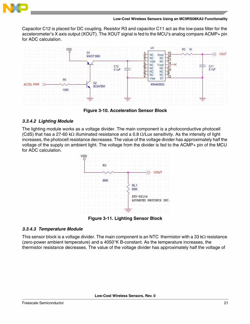
Capacitor C12 is placed for DC coupling. Resistor R3 and capacitor C11 act as the low-pass filter for the accelerometer’s X axis output (XOUT). The XOUT signal is fed to the MCU’s analog compare ACMP+ pin for ADC calculation.
Figure 3-10. Acceleration Sensor Block
3.3.4.2 Lighting Module
The lighting module works as a voltage divider. The main component is a photoconductive photocell (CdS) that has a 27-60 kΩ illuminated resistance and a 0.8 Ω/Lux sensitivity. As the intensity of light increases, the photocell resistance decreases. The value of the voltage divider has approximately half the voltage of the supply on ambient light. The voltage from the divider is fed to the ACMP+ pin of the MCU for ADC calculation.
Figure 3-11. Lighting Sensor Block
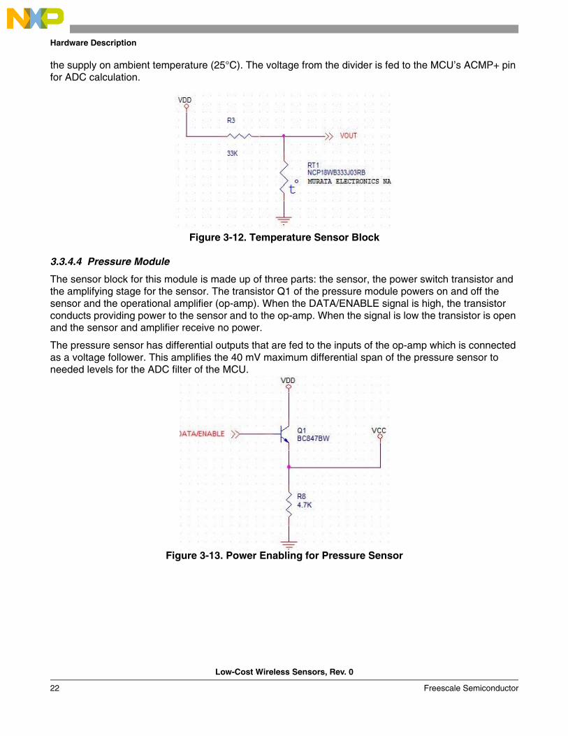
3.3.4.3 Temperature Module
This sensor block is a voltage divider. The main component is an NTC thermistor with a 33 kΩ resistance (zero-power ambient temperature) and a 4050°K B-constant. As the temperature increases, the thermistor resistance decreases. The value of the voltage divider has approximately half the voltage of
Hardware Description
Low-Cost Wireless Sensors, Rev. 0
22 Freescale Semiconductor
the supply on ambient temperature (25°C). The voltage from the divider is fed to the MCU’s ACMP+ pin for ADC calculation.
Figure 3-12. Temperature Sensor Block
3.3.4.4 Pressure Module
The sensor block for this module is made up of three parts: the sensor, the power switch transistor and the amplifying stage for the sensor. The transistor Q1 of the pressure module powers on and off the sensor and the operational amplifier (op-amp). When the DATA/ENABLE signal is high, the transistor conducts providing power to the sensor and to the op-amp. When the signal is low the transistor is open and the sensor and amplifier receive no power.
The pressure sensor has differential outputs that are fed to the inputs of the op-amp which is connected as a voltage follower. This amplifies the 40 mV maximum differential span of the pressure sensor to needed levels for the ADC filter of the MCU.
Figure 3-13. Power Enabling for Pressure Sensor

Low-Cost Wireless Sensors Using an MC9RS08KA2 Functionality
Low-Cost Wireless Sensors, Rev. 0
Freescale Semiconductor 23
Figure 3-14. Pressure Sensor Block with Amplifier
3.3.4.5 Ultrasound Module
The receiver of the ultrasound module sensor block has an amplifier to boost the received pulses to measurable levels for the MC9RS08KA2. A filter capacitor was placed to block any unwanted interference on the receivers.
Figure 3-15. Receiver for the Ultrasound Sensor Block
The transmitter has two jumpers (J4 and J5) for transmission:
Hardware Description
Low-Cost Wireless Sensors, Rev. 0
24 Freescale Semiconductor
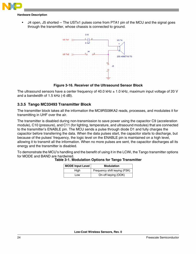
• J4 open, J5 shorted -- The USTx1 pulses come from PTA1 pin of the MCU and the signal goes through the transmitter, whose chassis is connected to ground.
Figure 3-16. Receiver of the Ultrasound Sensor Block
The ultrasound sensors have a center frequency of 40.0 kHz ± 1.0 kHz, maximum input voltage of 20 V and a bandwidth of 1.5 kHz (-6 dB).
3.3.5 Tango MC33493 Transmitter Block
The transmitter block takes all the information the MC9RS08KA2 reads, processes, and modulates it for transmitting in UHF over the air.
The transmitter is disabled during non-transmission to save power using the capacitor C9 (acceleration module), C10 (pressure), and C11 (for lighting, temperature, and ultrasound modules) that are connected to the transmitter’s ENABLE pin. The MCU sends a pulse through diode D1 and fully charges the capacitor before transferring the data. When the data pulses start, the capacitor starts to discharge, but because of the pulses’ frequency, the logic level on the ENABLE pin is maintained on a high level, allowing it to transmit all the information. When no more pulses are sent, the capacitor discharges all its energy and the transmitter is disabled.
To demonstrate the MCU’s handling and the benefit of using it in the LCWi, the Tango transmitter options for MODE and BAND are hardwired.
Table 3-1. Modulation Options for Tango Transmitter
MODE Input Level Modulation
High Frequency shift keying (FSK)
Low On-off keying (OOK)

Low-Cost Wireless Sensors Using an MC9RS08KA2 Functionality
Low-Cost Wireless Sensors, Rev. 0
Freescale Semiconductor 25
For more detailed and specific data about the MC33493 Tango transmitter configuration and features, refer to the data sheet, you can find it at www.freescale.com.
Crystal Y1 is a 9.84375 MHz crystal oscillator. The BAND and MODE pins are connected to VDD to select a 315 MHz transmission frequency and FSK modulation.
Figure 3-17. Transmitter Block
Table 3-2. Band Options for Tango Transmitter
BAND Input Level
Frequency Band (MHz)
PLL Divider Ratio
Crystal Oscillator Frequency (MHz)
High315
329.84
43413.56
Low 868 64
Hardware Description
Low-Cost Wireless Sensors, Rev. 0
26 Freescale Semiconductor
3.3.6 Antenna
3.3.6.1 RF Section
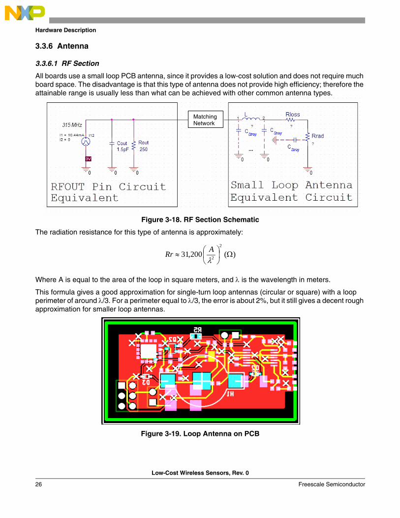
All boards use a small loop PCB antenna, since it provides a low-cost solution and does not require much board space. The disadvantage is that this type of antenna does not provide high efficiency; therefore the attainable range is usually less than what can be achieved with other common antenna types.
Figure 3-18. RF Section Schematic
The radiation resistance for this type of antenna is approximately:
Where A is equal to the area of the loop in square meters, and λ is the wavelength in meters.
This formula gives a good approximation for single-turn loop antennas (circular or square) with a loop perimeter of around λ/3. For a perimeter equal to λ/3, the error is about 2%, but it still gives a decent rough approximation for smaller loop antennas.
Figure 3-19. Loop Antenna on PCB
Matching Network
)(200,312
2 Ω⎟⎠⎞
⎜⎝⎛≈
λARr
Low-Cost Wireless Sensors Using an MC9RS08KA2 Functionality
Low-Cost Wireless Sensors, Rev. 0
Freescale Semiconductor 27
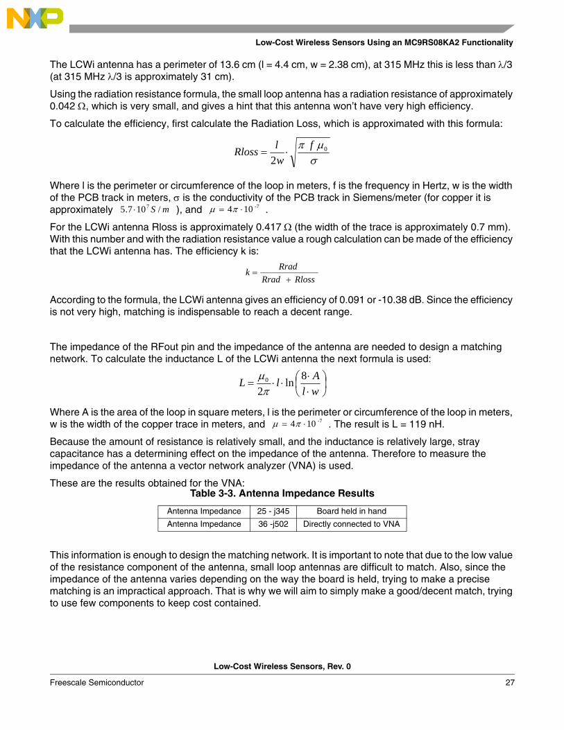
The LCWi antenna has a perimeter of 13.6 cm (l = 4.4 cm, w = 2.38 cm), at 315 MHz this is less than λ/3 (at 315 MHz λ/3 is approximately 31 cm).
Using the radiation resistance formula, the small loop antenna has a radiation resistance of approximately 0.042 Ω, which is very small, and gives a hint that this antenna won’t have very high efficiency.
To calculate the efficiency, first calculate the Radiation Loss, which is approximated with this formula:
Where l is the perimeter or circumference of the loop in meters, f is the frequency in Hertz, w is the width of the PCB track in meters, σ is the conductivity of the PCB track in Siemens/meter (for copper it is approximately ), and .
For the LCWi antenna Rloss is approximately 0.417 Ω (the width of the trace is approximately 0.7 mm). With this number and with the radiation resistance value a rough calculation can be made of the efficiency that the LCWi antenna has. The efficiency k is:
According to the formula, the LCWi antenna gives an efficiency of 0.091 or -10.38 dB. Since the efficiency is not very high, matching is indispensable to reach a decent range.
The impedance of the RFout pin and the impedance of the antenna are needed to design a matching network. To calculate the inductance L of the LCWi antenna the next formula is used:
Where A is the area of the loop in square meters, l is the perimeter or circumference of the loop in meters, w is the width of the copper trace in meters, and . The result is L = 119 nH.
Because the amount of resistance is relatively small, and the inductance is relatively large, stray capacitance has a determining effect on the impedance of the antenna. Therefore to measure the impedance of the antenna a vector network analyzer (VNA) is used.
These are the results obtained for the VNA:
This information is enough to design the matching network. It is important to note that due to the low value of the resistance component of the antenna, small loop antennas are difficult to match. Also, since the impedance of the antenna varies depending on the way the board is held, trying to make a precise matching is an impractical approach. That is why we will aim to simply make a good/decent match, trying to use few components to keep cost contained.
Table 3-3. Antenna Impedance Results
Antenna Impedance 25 - j345 Board held in hand
Antenna Impedance 36 -j502 Directly connected to VNA
σμπ 0
2f
wlRloss ⋅=
mS /107.5 7⋅ -7104 ⋅= πμ
RlossRradRradk
+=
⎟⎠⎞
⎜⎝⎛
⋅⋅
⋅⋅=wlAlL 8ln
20
πμ
-7104 ⋅= πμ
Hardware Description
Low-Cost Wireless Sensors, Rev. 0
28 Freescale Semiconductor
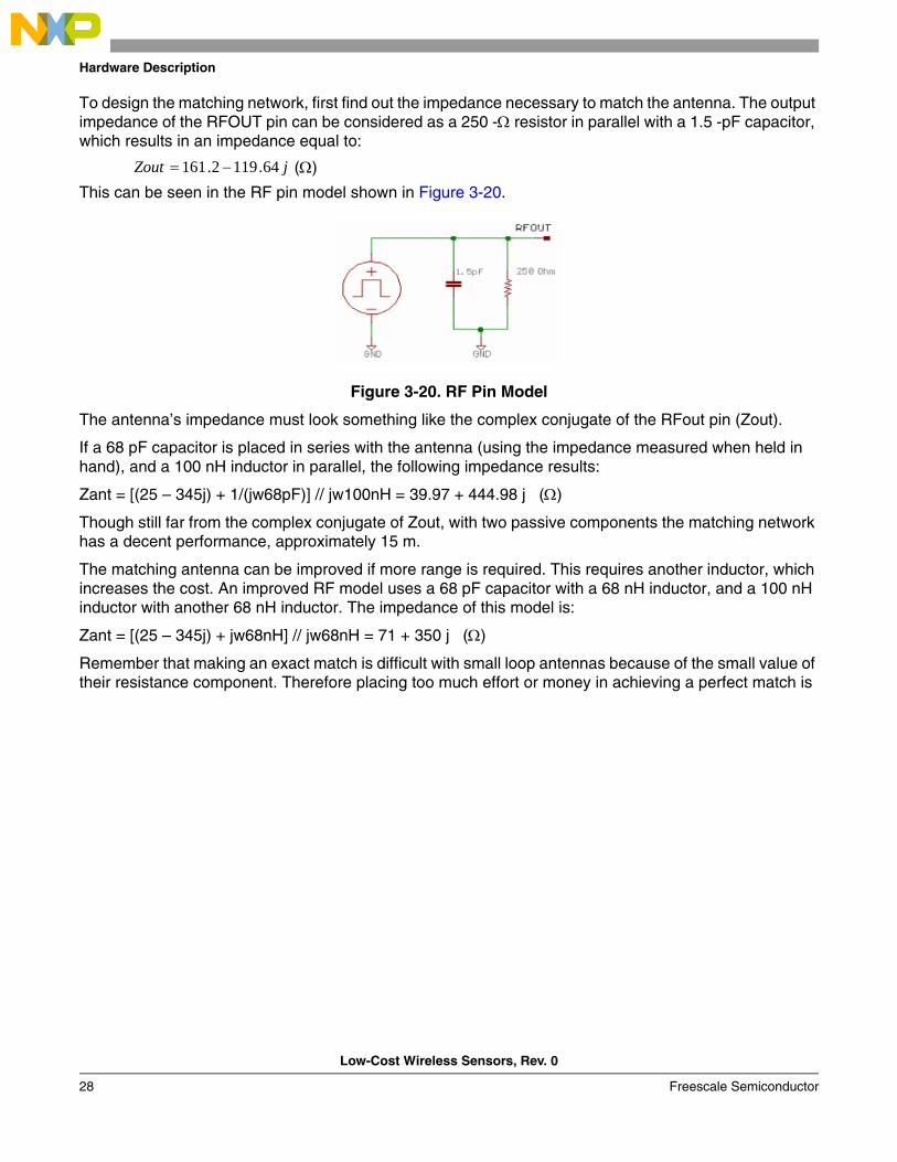
To design the matching network, first find out the impedance necessary to match the antenna. The output impedance of the RFOUT pin can be considered as a 250 -Ω resistor in parallel with a 1.5 -pF capacitor, which results in an impedance equal to:
(Ω)
This can be seen in the RF pin model shown in Figure 3-20.
Figure 3-20. RF Pin Model
The antenna’s impedance must look something like the complex conjugate of the RFout pin (Zout).
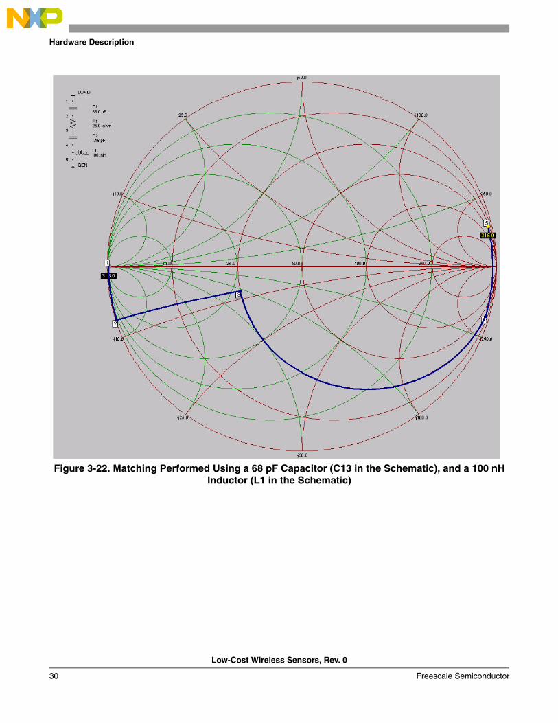
If a 68 pF capacitor is placed in series with the antenna (using the impedance measured when held in hand), and a 100 nH inductor in parallel, the following impedance results:
Zant = [(25 – 345j) + 1/(jw68pF)] // jw100nH = 39.97 + 444.98 j (Ω)
Though still far from the complex conjugate of Zout, with two passive components the matching network has a decent performance, approximately 15 m.
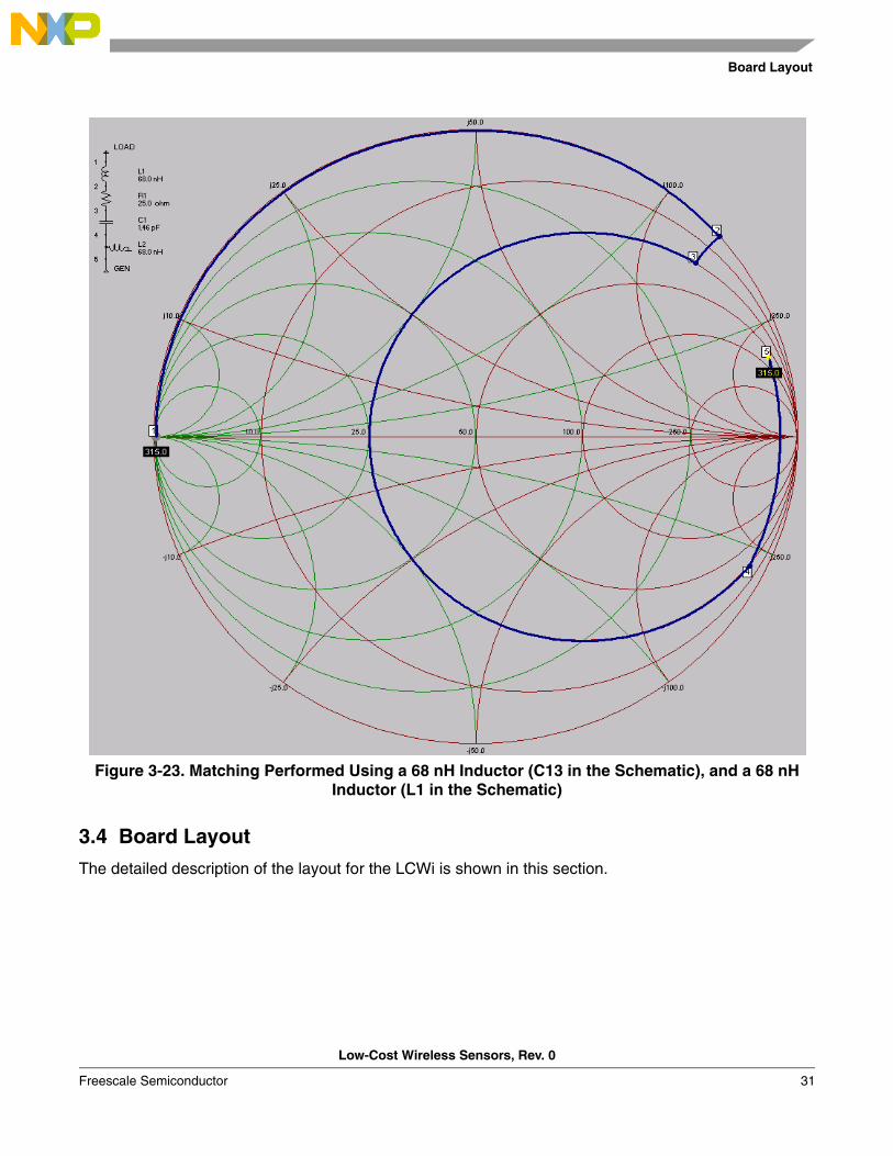
The matching antenna can be improved if more range is required. This requires another inductor, which increases the cost. An improved RF model uses a 68 pF capacitor with a 68 nH inductor, and a 100 nH inductor with another 68 nH inductor. The impedance of this model is:
Zant = [(25 – 345j) + jw68nH] // jw68nH = 71 + 350 j (Ω)
Remember that making an exact match is difficult with small loop antennas because of the small value of their resistance component. Therefore placing too much effort or money in achieving a perfect match is
jZout 64.1192.161 −=
Low-Cost Wireless Sensors Using an MC9RS08KA2 Functionality
Low-Cost Wireless Sensors, Rev. 0
Freescale Semiconductor 29
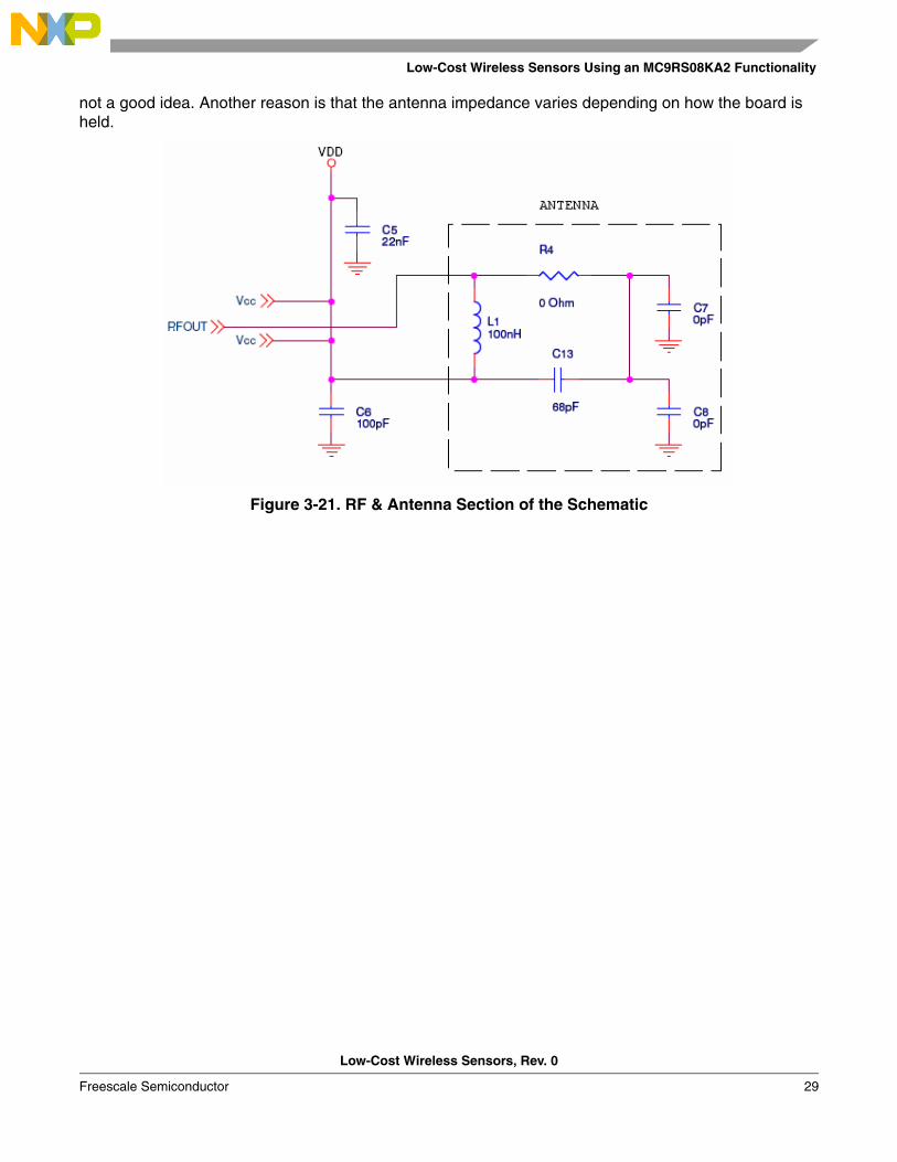
not a good idea. Another reason is that the antenna impedance varies depending on how the board is held.
Figure 3-21. RF & Antenna Section of the Schematic
Hardware Description
Low-Cost Wireless Sensors, Rev. 0
30 Freescale Semiconductor
Figure 3-22. Matching Performed Using a 68 pF Capacitor (C13 in the Schematic), and a 100 nH Inductor (L1 in the Schematic)
Board Layout
Low-Cost Wireless Sensors, Rev. 0
Freescale Semiconductor 31
Figure 3-23. Matching Performed Using a 68 nH Inductor (C13 in the Schematic), and a 68 nH Inductor (L1 in the Schematic)
3.4 Board Layout
The detailed description of the layout for the LCWi is shown in this section.
Hardware Description
Low-Cost Wireless Sensors, Rev. 0
32 Freescale Semiconductor
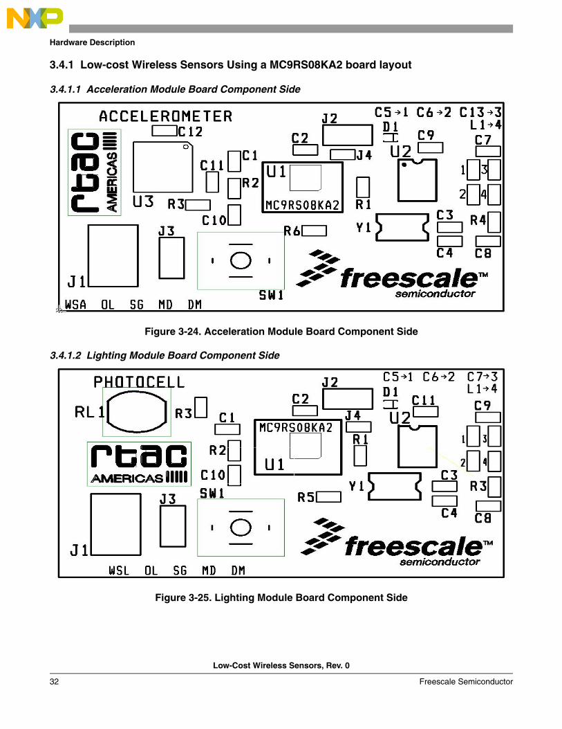
3.4.1 Low-cost Wireless Sensors Using a MC9RS08KA2 board layout
3.4.1.1 Acceleration Module Board Component Side
Figure 3-24. Acceleration Module Board Component Side
3.4.1.2 Lighting Module Board Component Side
Figure 3-25. Lighting Module Board Component Side

Board Layout
Low-Cost Wireless Sensors, Rev. 0
Freescale Semiconductor 33
3.4.1.3 Pressure Module Board Component Side
Figure 3-26. Pressure Module Board Component Side
3.4.1.4 Temperature Module Board Component Side
Figure 3-27. Temperature Module Board Component Side
Hardware Description
Low-Cost Wireless Sensors, Rev. 0
34 Freescale Semiconductor
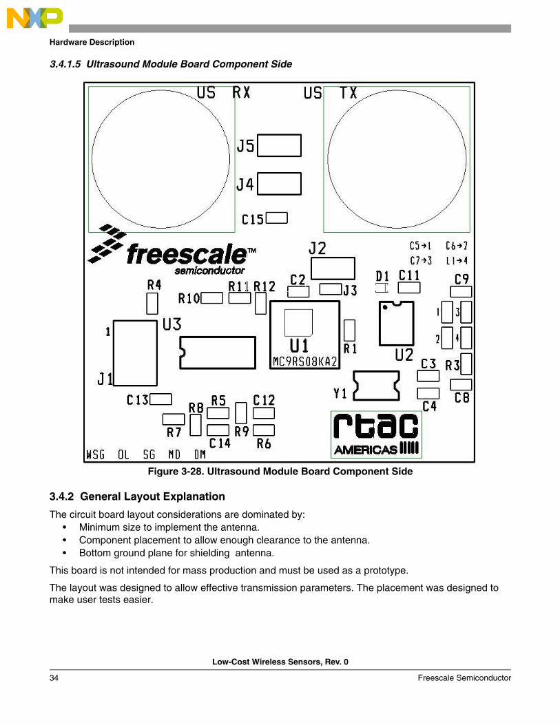
3.4.1.5 Ultrasound Module Board Component Side
Figure 3-28. Ultrasound Module Board Component Side
3.4.2 General Layout Explanation
The circuit board layout considerations are dominated by:• Minimum size to implement the antenna.• Component placement to allow enough clearance to the antenna.• Bottom ground plane for shielding antenna.
This board is not intended for mass production and must be used as a prototype.
The layout was designed to allow effective transmission parameters. The placement was designed to make user tests easier.
Board Layout
Low-Cost Wireless Sensors, Rev. 0
Freescale Semiconductor 35
3.4.3 PCB Features
3.4.3.1 Board Size
The circuit board size is 1 x 1.8 inches for the acceleration, lighting, pressure, and temperature modules.
The circuit board size is 1.75 x 1.8 inches for the ultrasound module.
The form of the board was designed for a better implementation of the dipole antenna.
3.4.3.2 Two Layers
The majority of signals are routed on the top layer. Some signals are on the bottom layer because of component density and the board size. To maintain the same board size for all modules, some components are placed on the bottom side.
Ground planes were used to maintain signal integrity and to shield the antenna for effective transmission parameters.
3.4.3.3 Board Material FR-4
The FR-4 materials are predominantly used for printed circuit boards. The FR-4 materials can withstand 130°C. FR-404 and FR406 have higher temperature ratings (150°C and 170°C, respectively).
3.4.3.4 Minimum Circuit Board Trace Width for Signal Traces
Circuit board vendors indicate the following minimum trace widths for a given copper plating thickness. • 1 oz. Cu – 5 mil lines• 2 oz. Cu – 7 mil lines• 3 oz. Cu – 10 mil lines
0.009 inches is the board’s minimum trace width and clearance. The LCWi uses a 1 oz Cu thickness because there are not high current signals on the board, so the 0.009 inches trace width is enough.
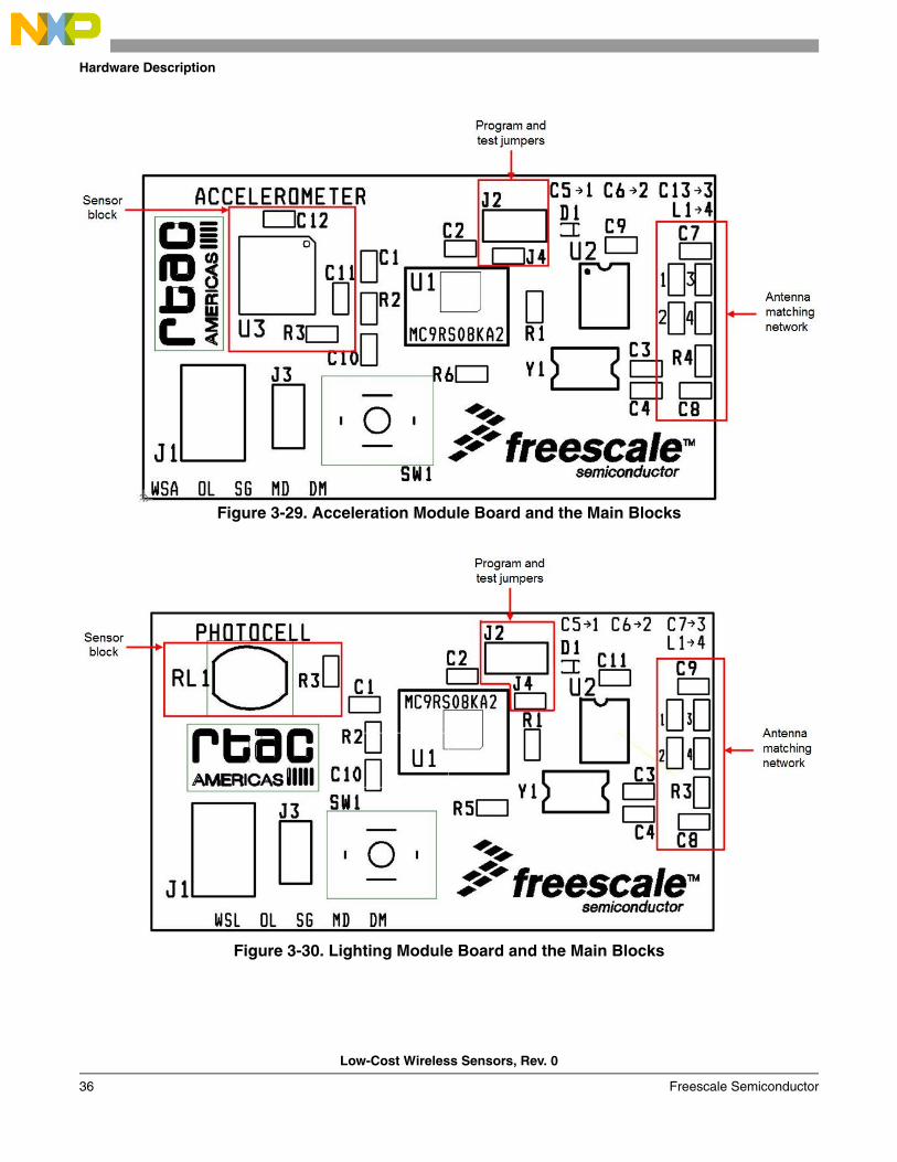
3.4.4 Component Placement
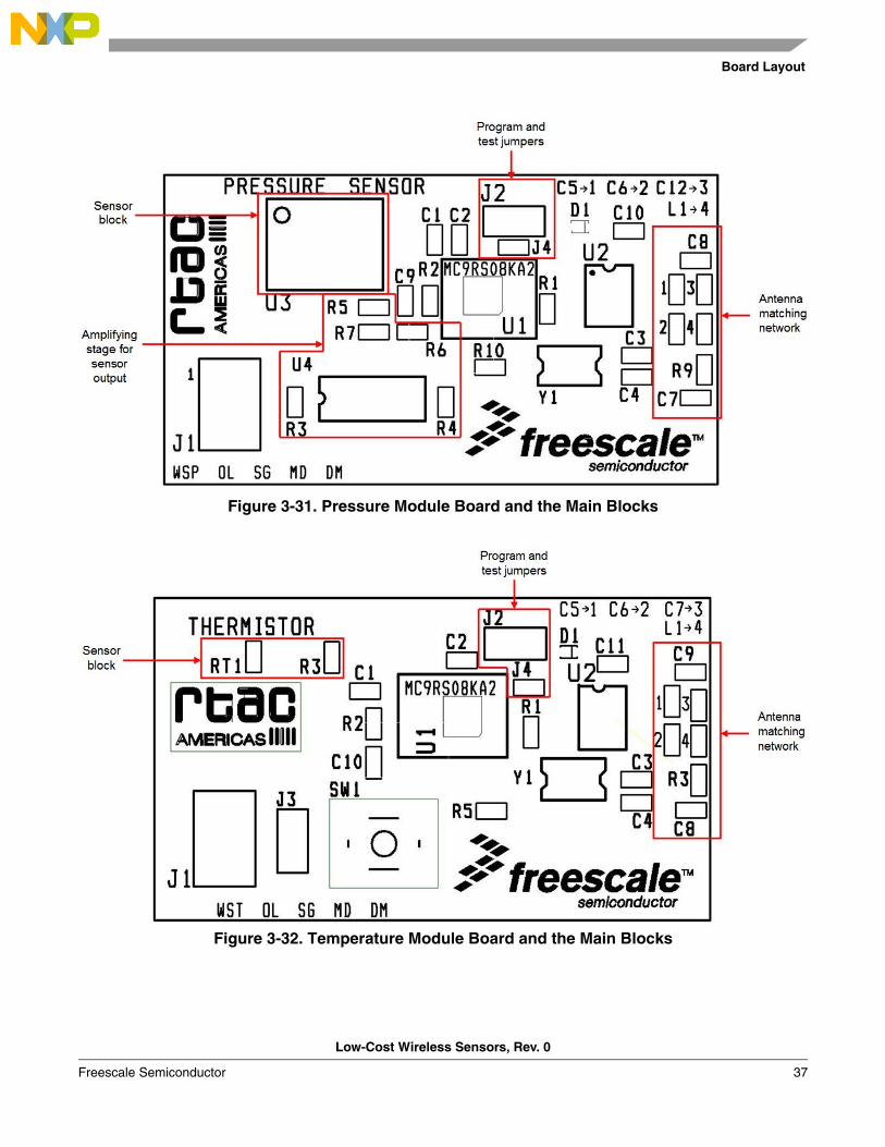
Figure 3-29 through Figure 3-33 illustrate how the main blocks are separated. The processing unit, sensor blocks, BDM connector, and transmitter blocks are placed with enough clearance distance to avoid interference with the antenna.
Hardware Description
Low-Cost Wireless Sensors, Rev. 0
36 Freescale Semiconductor
Figure 3-29. Acceleration Module Board and the Main Blocks
Figure 3-30. Lighting Module Board and the Main Blocks
Board Layout
Low-Cost Wireless Sensors, Rev. 0
Freescale Semiconductor 37
Figure 3-31. Pressure Module Board and the Main Blocks
Figure 3-32. Temperature Module Board and the Main Blocks
Hardware Description
Low-Cost Wireless Sensors, Rev. 0
38 Freescale Semiconductor
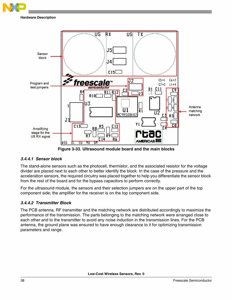
Figure 3-33. Ultrasound module board and the main blocks
3.4.4.1 Sensor block
The stand-alone sensors such as the photocell, thermistor, and the associated resistor for the voltage divider are placed next to each other to better identify the block. In the case of the pressure and the acceleration sensors, the required circuitry was placed together to help you differentiate the sensor block from the rest of the board and for the bypass capacitors to perform correctly.
For the ultrasound module, the sensors and their selection jumpers are on the upper part of the top component side; the amplifier for the receiver is on the top component side.
3.4.4.2 Transmitter Block
The PCB antenna, RF transmitter and the matching network are distributed accordingly to maximize the performance of the transmission. The parts belonging to the matching network were arranged close to each other and to the transmitter to avoid any noise induction in the transmission lines. For the PCB antenna, the ground plane was ensured to have enough clearance to it for optimizing transmission parameters and range.
Board Layout
Low-Cost Wireless Sensors, Rev. 0
Freescale Semiconductor 39
3.4.4.3 BDM Connector
Table 3-4 shows the signals for the BDM connector, a 3 x 2 pin header.
3.4.4.4 Processing Unit Block
For the placement of the processing unit block the only important consideration is to have the bypass capacitor for the MCU placed as close to the power supply pin as possible.
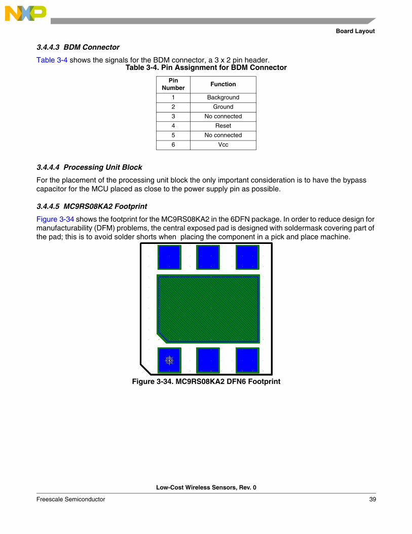
3.4.4.5 MC9RS08KA2 Footprint
Figure 3-34 shows the footprint for the MC9RS08KA2 in the 6DFN package. In order to reduce design for manufacturability (DFM) problems, the central exposed pad is designed with soldermask covering part of the pad; this is to avoid solder shorts when placing the component in a pick and place machine.
Figure 3-34. MC9RS08KA2 DFN6 Footprint
Table 3-4. Pin Assignment for BDM Connector
Pin Number
Function
1 Background
2 Ground
3 No connected
4 Reset
5 No connected
6 Vcc
Hardware Description
Low-Cost Wireless Sensors, Rev. 0
40 Freescale Semiconductor
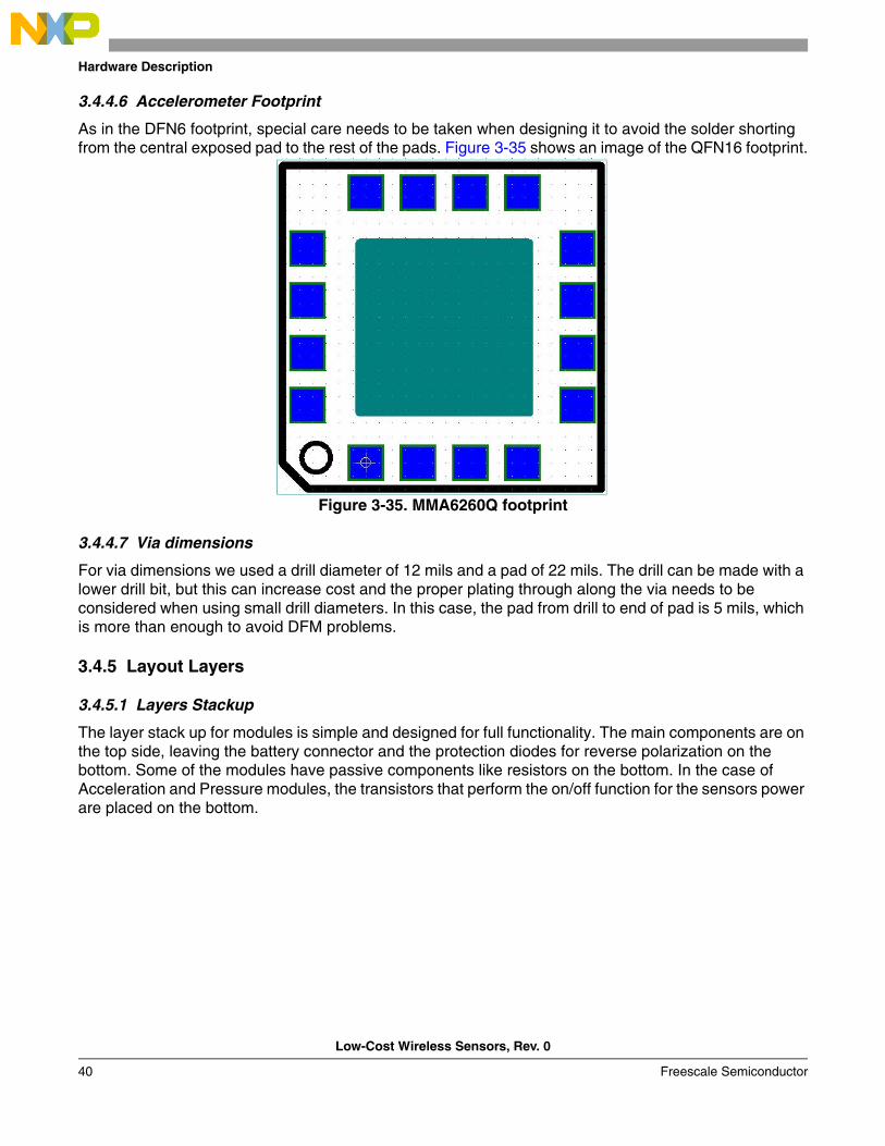
3.4.4.6 Accelerometer Footprint
As in the DFN6 footprint, special care needs to be taken when designing it to avoid the solder shorting from the central exposed pad to the rest of the pads. Figure 3-35 shows an image of the QFN16 footprint.
Figure 3-35. MMA6260Q footprint
3.4.4.7 Via dimensions
For via dimensions we used a drill diameter of 12 mils and a pad of 22 mils. The drill can be made with a lower drill bit, but this can increase cost and the proper plating through along the via needs to be considered when using small drill diameters. In this case, the pad from drill to end of pad is 5 mils, which is more than enough to avoid DFM problems.
3.4.5 Layout Layers
3.4.5.1 Layers Stackup
The layer stack up for modules is simple and designed for full functionality. The main components are on the top side, leaving the battery connector and the protection diodes for reverse polarization on the bottom. Some of the modules have passive components like resistors on the bottom. In the case of Acceleration and Pressure modules, the transistors that perform the on/off function for the sensors power are placed on the bottom.
Board Layout
Low-Cost Wireless Sensors, Rev. 0
Freescale Semiconductor 41
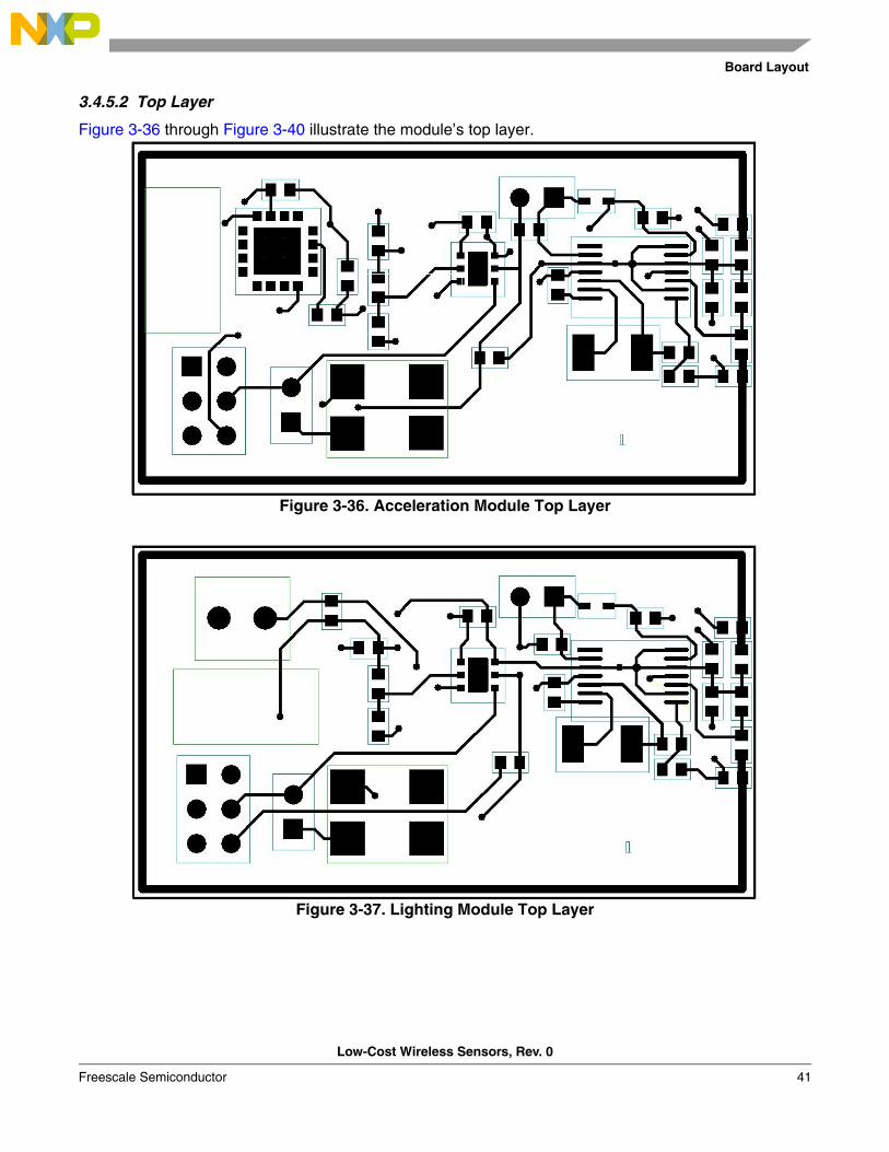
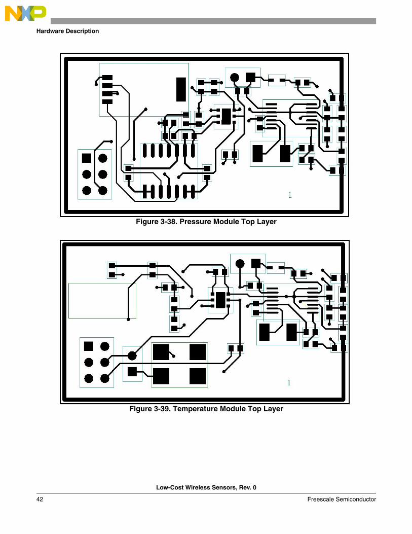
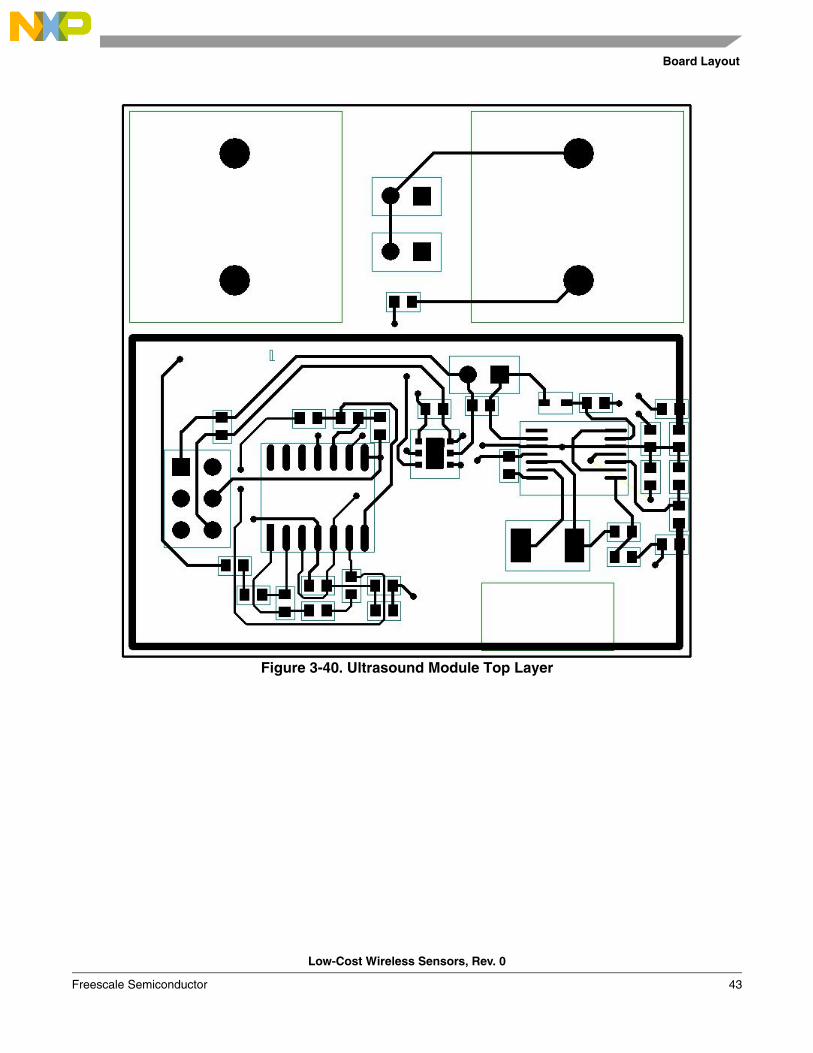
3.4.5.2 Top Layer
Figure 3-36 through Figure 3-40 illustrate the module’s top layer.
Figure 3-36. Acceleration Module Top Layer
Figure 3-37. Lighting Module Top Layer
Hardware Description
Low-Cost Wireless Sensors, Rev. 0
42 Freescale Semiconductor
Figure 3-38. Pressure Module Top Layer
Figure 3-39. Temperature Module Top Layer
Board Layout
Low-Cost Wireless Sensors, Rev. 0
Freescale Semiconductor 43
Figure 3-40. Ultrasound Module Top Layer
Hardware Description
Low-Cost Wireless Sensors, Rev. 0
44 Freescale Semiconductor
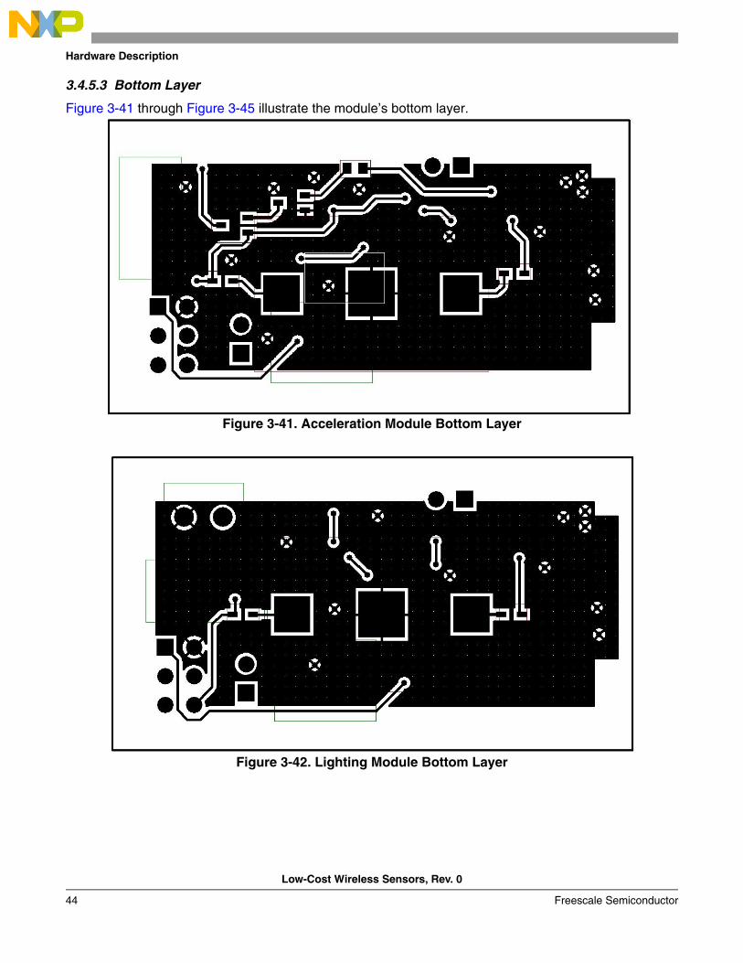
3.4.5.3 Bottom Layer
Figure 3-41 through Figure 3-45 illustrate the module’s bottom layer.
Figure 3-41. Acceleration Module Bottom Layer
Figure 3-42. Lighting Module Bottom Layer
Board Layout
Low-Cost Wireless Sensors, Rev. 0
Freescale Semiconductor 45
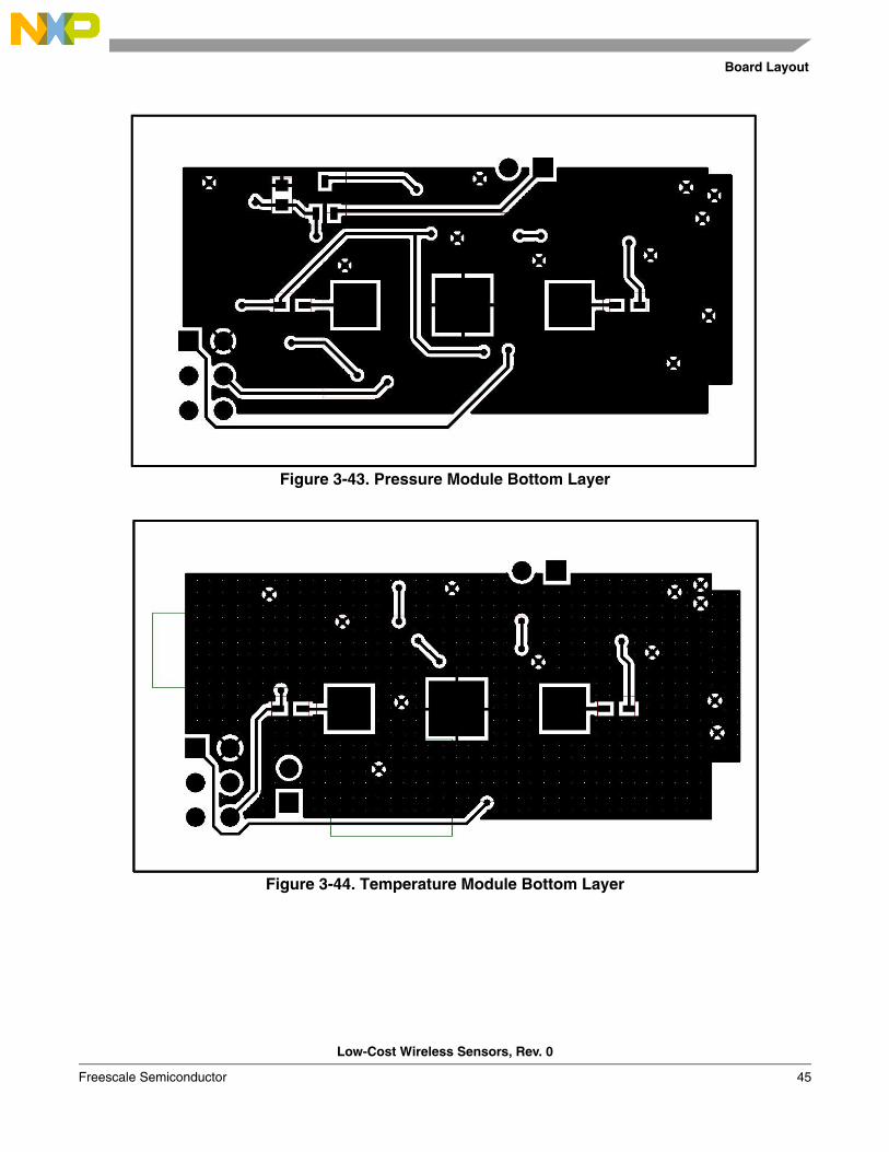
Figure 3-43. Pressure Module Bottom Layer
Figure 3-44. Temperature Module Bottom Layer
Hardware Description
Low-Cost Wireless Sensors, Rev. 0
46 Freescale Semiconductor
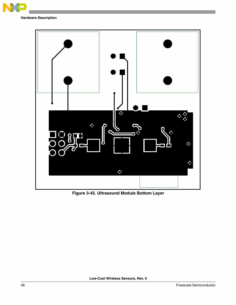
Figure 3-45. Ultrasound Module Bottom Layer
Low-Cost Wireless Sensors, Rev. 0
Freescale Semiconductor 47
Chapter 4 Firmware Description
4.1 Introduction
This section of the reference design provides complete firmware documentation of the Low-Cost Wireless Sensors Using an MC9RS08KA2 (LCWi).
All firmware applications demonstrate the MC9RS08KA2 capacity to work with analog devices such as, the RF transmitters, sensors and op-amps. The basic analog sensors used in this reference design are: temperature, pressure, accelerometer, ultrasonic, photoresistor, and push-button
4.1.1 Firmware Basics
All embedded software of this project was written using CodeWarriorTM Development Studio for Freescale HC(S) 08/RS08 Microcontrollers, V5.1 which is Windows supported and can be downloaded at www.freescale.com.
4.1.2 Application Basics
This application’s main purpose is monitoring the environment for different situations such as temperature, pressure, object positions, distance measurement, push-button, and lighting environment. These are controlled by an MC9RS08KA2 and the Tango RF Transmitter (MC33493).
4.2 Project Introduction
This section introduces and describes the firmware implementation.
4.2.1 Coding Conventions
All source codes are written in assembly language using several rules that make the final product more readable and reusable.
• Subroutines -- The main subroutine names for the Tango, ADC and TEAMAC drivers are written with capital letters and underscores after the driver name, for example, ADC_RECEIVE. Other subroutine names are written in uppercase at the beginning and underscored between words.
• Macros -- All macro names are written in capital letters, underscored, and follow the declaration, for example, TRIM_ICS: MACRO
• Tags -- All tags start in the first column of the code line.
4.2.2 Project Files
Files required for the project:

Firmware Description
Low-Cost Wireless Sensors, Rev. 0
48 Freescale Semiconductor
The following project files can be found inside the TANGOKA2SW folder. This folder contains three sub folders:
1. TangoKA2 -- contains the basic code to make all the wireless sensor applications (Tango driver, ADC driver, Encrypt algorithm and a basic main loop);
2. Sensor Applications -- contains all wireless sensors’ applications that use the basic code from the TangoKA2 folder;
3. RomeoAP64 – contains the basic code for the Romeo RF receiver that is controlled with the 68HC908AP64.
Files for the MC9RS08KA2:• Applications Project files (CodeWarrior tool project files):
– Accelerometer.mcp – Pressure.mcp – Temperature.mcp – Ultrasonic.mcp – PushButton.mcp– Light.mcp
• Applications Source files (Contain the main application):– Accelerometer.asm – Pressure.asm – Temperature.asm – Ultrasonic.asm – PushButton.asm – Light.asm
• Driver files (must be included in all application projects):– TangoDriver.asm – RTeamac.asm – ADCdriver.asm (Not included in ultrasonic and push button projects).
Files for the 68HC908AP64:• Applications Project files (CodeWarrior tool project files):
– RomeoAP64.mcp • Applications Source files (Contain the main application):
– Romeo.c– Teamac.c
• Applications Header files– Teamac.h
4.2.3 Implemented MCU Peripherals
This section briefly describes the MC9RS08KA2 peripherals in the project and summarizes the necessary MCU resources.
Project Introduction
Low-Cost Wireless Sensors, Rev. 0
Freescale Semiconductor 49
4.2.3.1 Implemented Interrupts
Table 4-1 lists all interrupts used within the LCWi.
4.2.3.2 Main Variables of Drivers
Some of the most important variables and flags within the drivers are the following, which are also declared globally and used to control each application’s functionality:
• key • TEAMAC_DATA • TEAMAC_CODE • DATA • Aux • sum • y • z • SensorReading • ConvertedValue• Temp_Page
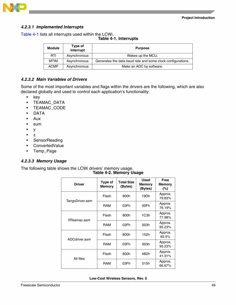
4.2.3.3 Memory Usage
The following table shows the LCWi drivers’ memory usage.
Table 4-1. Interrupts
ModuleType of
InterruptPurpose
RTI Asynchronous Wakes up the MCU.
MTIM Asynchronous Generates the data baud rate and some clock configurations.
ACMP Asynchronous Make an ADC by software.
Table 4-2. Memory Usage
DriverType of Memory
Total Size (Bytes)
Used Memory (Bytes)
Free Memory
(%)
TangoDriver.asmFlash 800h 19Dh
Approx. 79.83%
RAM 03Fh 00FhApprox.76.19%
RTeamac.asmFlash 800h 1C3h
Approx. 77.98%
RAM 03Fh 003hApprox. 95.23%
ADCdriver.asmFlash 800h 152h
Approx. 83.5%
RAM 03Fh 003hApprox. 95.23%
All filesFlash 800h 4B2h
Approx. 41.31%
RAM 03Fh 015hApprox. 66.67%
Firmware Description
Low-Cost Wireless Sensors, Rev. 0
50 Freescale Semiconductor
4.3 Firmware Implementation
In this section the complete description of the key firmware modules of the LCWi is given.
4.3.1 Drivers Implementation
4.3.1.1 Tango RF Transmitter Driver
The Tango RF transmitter driver is in the TangoDriver.asm file. This driver provides the user the capability to send encrypted data via wireless.
The Tango RF transmitter driver controls the communication protocol between the MC9RS08KA2 and the Tango (MC33493). This communication protocol uses the Manchester coding and the Frequency-shift keying (FSK) modulation.
The main subroutine of this driver is TANGO_SEND_DATA. It is important to use one of the two baud rate macro configurations (BAUD_1400 or BAUD_2700) before calling this subroutine. The BAUD_2700 macro is the default baud rate configuration for all the LCWi modules. This baud rate must be configured in, the Transmitter (Tango) and the Receiver (Romeo) by firmware instructions. If you change the baud rate in the Tango RF transmitter driver you must change the baud rate in the Romeo RF receiver too.
To configure the baud rate on the Romeo RF Receiver:1. The cr3 register is declared within the void main program.2. If the value is 0x00, then the baud rate is set to 1400 bits per second (bps).3. The default value is 0x40, which sets the baud rate to 2700 bps.4. Set the desire baud rate, then build the project and download it to the 68HC908AP64. See
Section 4.4 Programming LCWi boards and DEMO908AP64.void main(void) CONFIG1 = 0x03; /* Disable COP, enable STOP instruction */...
cr1 = 0x3F;cr2 = 0xA5;cr3 = 0x40; Romeo_Transfer();cr1 = cr1 | 80;Romeo_Transfer();...
The TANGO_SEND_DATA subroutine:1. Sends the Preamble and ID. The ID must be recognized by the Romeo RF Receiver. 2. Then, it sends the Preamble and Header byte. The communication protocol for the Romeo2
MC33591 is explained in its technical data, which can be found in www.freescale.com.3. Next, the information data is sent, in the following order:
1. (TEAMAC_DATA) -- The encrypt data that is composed by two bytes of operator numbers.
2. (TEAMAC_CODE) -- One byte of result.
3. Sensor group -- Is the fourth byte sent, Table 4-3 shows the sensors groups and values.

Firmware Implementation
Low-Cost Wireless Sensors, Rev. 0
Freescale Semiconductor 51
4. Sensor ID -- Is the fifth byte sent, which is different to the ID received by the Romeo RF Receiver. The Sensor ID must be configured when there is more than one sensor on the same group.
5. The sixth and seventh bytes to send are the data information. The data information for this reference design belongs to the sensors.
To configure or rename a Sensor ID:1. In the TangoDriver.asm (inside the Sources folder), look for these code lines:
;*********************************************************************** ;* Driver Constants *;*********************************************************************** TANGO_FSK_HEADER EQU $60 ; FSK preamble (4 0's) and Header (0110)DELTA EQU $9EID EQU $A5 ; Romeo ID recognized
;*********** These constants can be modified by users ******************ID2 EQU $01 ; Sensor IDGROUP EQU $41 ; Sensor Group
2. The ID2 constant is the Sensor ID constant. 3. The default Sensor ID is 1 in hexadecimal format. 4. Change this value, when you have more than two sensors of the same group. The new ID must be
in hexadecimal format and cannot be the same as another sensor of the same group.5. Build the project and download it to the MC9RS08KA2. For building and downloading information
see the Section 4.4 Programming LCWi boards and DEMO908AP64.
4.3.1.2 Reduce Encrypt TEAMAC Algorithm Driver
The encrypt algorithm is within the RTeamac.asm file that is included in the TangoDriver.asm file. The employed variables for this driver are in the TangoDriver.asm file.
This encrypt algorithm was based on the Teamac software algorithm, using 16 bytes instead of 64 bytes as the original. For this reason this encrypt algorithm was called reduce encrypt TEAMAC algorithm (RETA).
Basically, the encrypt algorithm generates an 8-bit message authentication code (MAC) from 16 bits of data and 16 bits of key.
The encrypt subroutine is called “ENCRYPT_TEAMAC”. This subroutine encrypts the Sensors ID stored in the variable TEAMAC_DATA, it performs a math operation with the TEAMAC_DATA and the key. The
Table 4-3. Sensors Groups and Values
Sensor GroupHexadecimal
Value
Accelerometer A 41h
Temperature T 54h
Ultrasonic U 55h
Pressure R 52h
Light I 49h
Push-button P 50h
Firmware Description
Low-Cost Wireless Sensors, Rev. 0
52 Freescale Semiconductor
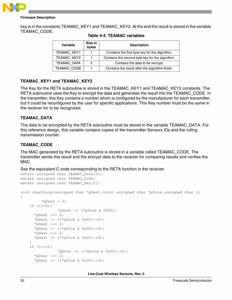
key is in the constants TEAMAC_KEY1 and TEAMAC_KEY2. At the end the result is stored in the variable TEAMAC_CODE.
TEAMAC_KEY1 and TEAMAC_KEY2
The Key for the RETA subroutine is stored in the TEAMAC_KEY1 and TEAMAC_KEY2 constants. The RETA subroutine uses the Key to encrypt the data and generates the result into the TEAMAC_CODE. In the transmitter, this Key contains a number which is configured by the manufacturer for each transmitter, but it could be reconfigured by the user for specific applications. This Key number must be the same in the receiver for to be recognized.
TEAMAC_DATA
The data to be encrypted by the RETA subroutine must be stored in the variable TEAMAC_DATA. For this reference design, this variable contains copies of the transmitter Sensors IDs and the rolling transmission counter.
TEAMAC_CODE
The MAC generated by the RETA subroutine is stored in a variable called TEAMAC_CODE. The transmitter sends this result and the encrypt data to the receiver for comparing results and verifies the MAC.
See the equivalent C code corresponding to the RETA function in the receiver.extern unsigned char TEAMAC_Data[2];extern unsigned char TEAMAC_Code;extern unsigned char TEAMAC_Key[2];
void char2Long(unsigned char *pDest,const unsigned char *pSrce,unsigned char i)
*pDest = 0; if (i==0)
*pDest |= (*pSrce & 0x03); *pDest <<= 2; *pDest |= ((*pSrce & 0x0C)>>2); *pDest <<= 2; *pDest |= ((*pSrce & 0x30)>>4); *pDest <<= 2; *pDest |= ((*pSrce & 0xC0)>>6); if (i==1)
*pDest |= ((*pSrce & 0x0C)>>2); *pDest <<= 2; *pDest |= ((*pSrce & 0x30)>>4);
Table 4-4. TEAMAC variables
VariableSize in bytes
Description
TEAMAC_KEY1 1 Contains the first byte key for the algorithm.
TEAMAC_KEY2 1 Contains the second byte key for the algorithm.
TEAMAC_DATA 2 Contains the data to be encrypt.
TEAMAC_CODE 1 Contains the result after the algorithm finish.
Firmware Implementation
Low-Cost Wireless Sensors, Rev. 0
Freescale Semiconductor 53
*pDest <<= 2; *pDest |= ((*pSrce & 0xC0)>>6); *pDest <<= 2; *pDest |= (*(pSrce+1) & 0x03); if (i==2)
*pDest |= ((*pSrce & 0x30)>>4); *pDest <<= 2; *pDest |= ((*pSrce & 0xC0)>>6); *pDest <<= 2; *pDest |= (*(pSrce+1) & 0x03); *pDest <<= 2; *pDest |= ((*(pSrce+1) & 0x0C)>>2); if (i==4)
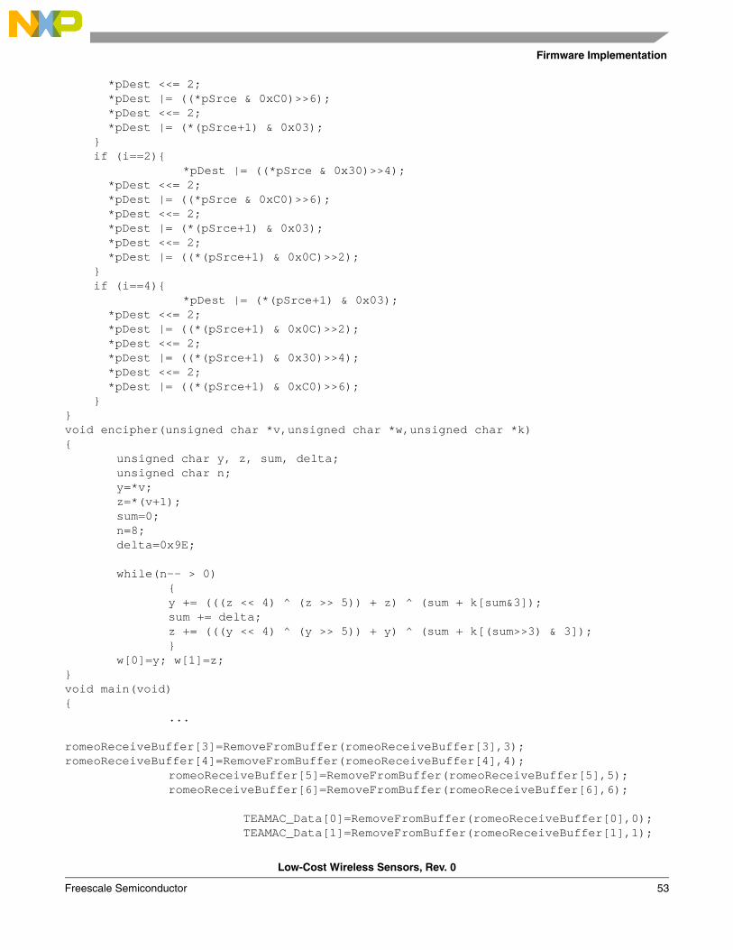
*pDest |= (*(pSrce+1) & 0x03); *pDest <<= 2; *pDest |= ((*(pSrce+1) & 0x0C)>>2); *pDest <<= 2; *pDest |= ((*(pSrce+1) & 0x30)>>4); *pDest <<= 2; *pDest |= ((*(pSrce+1) & 0xC0)>>6); void encipher(unsigned char *v,unsigned char *w,unsigned char *k)
unsigned char y, z, sum, delta;unsigned char n;y=*v;z=*(v+1);sum=0;n=8;delta=0x9E;
while(n-- > 0)y += (((z << 4) ^ (z >> 5)) + z) ^ (sum + k[sum&3]);sum += delta;z += (((y << 4) ^ (y >> 5)) + y) ^ (sum + k[(sum>>3) & 3]);
w[0]=y; w[1]=z;void main(void)
...
romeoReceiveBuffer[3]=RemoveFromBuffer(romeoReceiveBuffer[3],3); romeoReceiveBuffer[4]=RemoveFromBuffer(romeoReceiveBuffer[4],4); romeoReceiveBuffer[5]=RemoveFromBuffer(romeoReceiveBuffer[5],5); romeoReceiveBuffer[6]=RemoveFromBuffer(romeoReceiveBuffer[6],6); TEAMAC_Data[0]=RemoveFromBuffer(romeoReceiveBuffer[0],0); TEAMAC_Data[1]=RemoveFromBuffer(romeoReceiveBuffer[1],1);
Firmware Description
Low-Cost Wireless Sensors, Rev. 0
54 Freescale Semiconductor
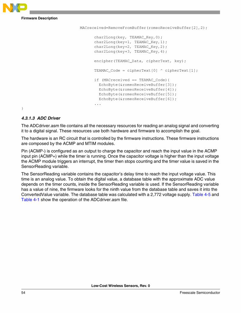
MACreceived=RemoveFromBuffer(romeoReceiveBuffer[2],2);
char2Long(key, TEAMAC_Key,0); char2Long(key+1, TEAMAC_Key,1); char2Long(key+2, TEAMAC_Key,2); char2Long(key+3, TEAMAC_Key,4);
encipher(TEAMAC_Data, cipherText, key);
TEAMAC_Code = cipherText[0] ^ cipherText[1]; if (MACreceived == TEAMAC_Code) EchoByte(&romeoReceiveBuffer[3]); EchoByte(&romeoReceiveBuffer[4]); EchoByte(&romeoReceiveBuffer[5]); EchoByte(&romeoReceiveBuffer[6]); ...
4.3.1.3 ADC Driver
The ADCdriver.asm file contains all the necessary resources for reading an analog signal and converting it to a digital signal. These resources use both hardware and firmware to accomplish the goal.
The hardware is an RC circuit that is controlled by the firmware instructions. These firmware instructions are composed by the ACMP and MTIM modules.
Pin (ACMP-) is configured as an output to charge the capacitor and reach the input value in the ACMP input pin (ACMP+) while the timer is running. Once the capacitor voltage is higher than the input voltage the ACMP module triggers an interrupt, the timer then stops counting and the timer value is saved in the SensorReading variable.
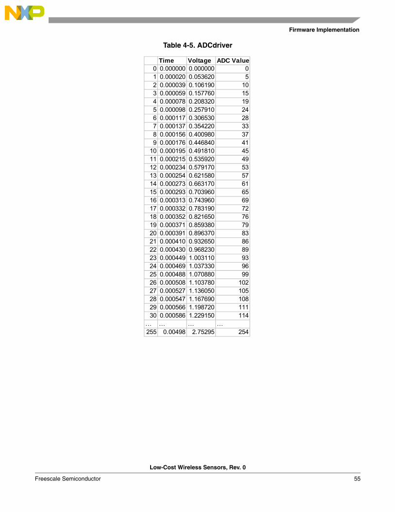
The SensorReading variable contains the capacitor’s delay time to reach the input voltage value. This time is an analog value. To obtain the digital value, a database table with the approximate ADC value depends on the timer counts, inside the SensorReading variable is used. If the SensorReading variable has a value of nine, the firmware looks for the ninth value from the database table and saves it into the ConvertedValue variable. The database table was calculated with a 2,772 voltage supply. Table 4-5 and Table 4-1 show the operation of the ADCdriver.asm file.
Firmware Implementation
Low-Cost Wireless Sensors, Rev. 0
Freescale Semiconductor 55
Table 4-5. ADCdriver
Time Voltage ADC Value0 0.000000 0.000000 01 0.000020 0.053620 52 0.000039 0.106190 103 0.000059 0.157760 154 0.000078 0.208320 195 0.000098 0.257910 246 0.000117 0.306530 287 0.000137 0.354220 338 0.000156 0.400980 379 0.000176 0.446840 41
10 0.000195 0.491810 4511 0.000215 0.535920 4912 0.000234 0.579170 5313 0.000254 0.621580 5714 0.000273 0.663170 6115 0.000293 0.703960 6516 0.000313 0.743960 6917 0.000332 0.783190 7218 0.000352 0.821650 7619 0.000371 0.859380 7920 0.000391 0.896370 8321 0.000410 0.932650 8622 0.000430 0.968230 8923 0.000449 1.003110 9324 0.000469 1.037330 9625 0.000488 1.070880 9926 0.000508 1.103780 10227 0.000527 1.136050 10528 0.000547 1.167690 10829 0.000566 1.198720 11130 0.000586 1.229150 114
… … … …255 0.00498 2.75295 254
Firmware Description
Low-Cost Wireless Sensors, Rev. 0
56 Freescale Semiconductor
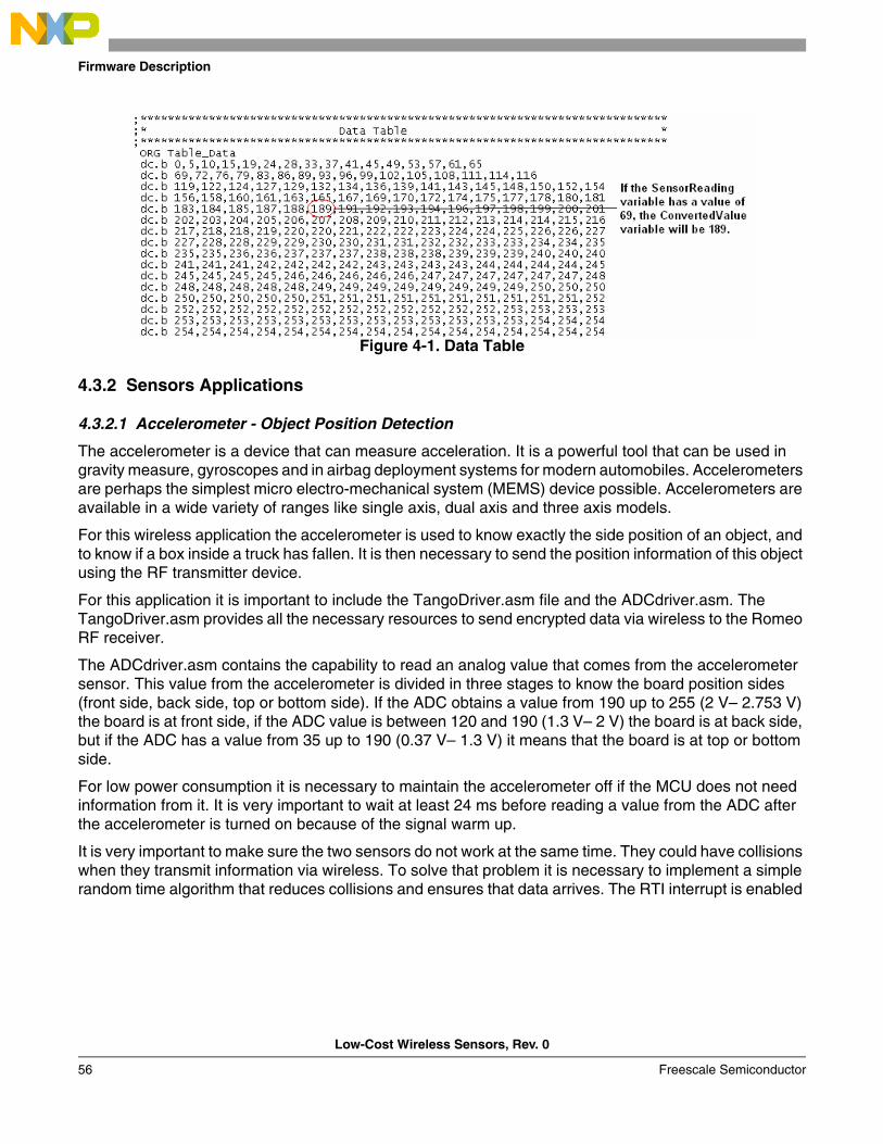
Figure 4-1. Data Table
4.3.2 Sensors Applications
4.3.2.1 Accelerometer - Object Position Detection
The accelerometer is a device that can measure acceleration. It is a powerful tool that can be used in gravity measure, gyroscopes and in airbag deployment systems for modern automobiles. Accelerometers are perhaps the simplest micro electro-mechanical system (MEMS) device possible. Accelerometers are available in a wide variety of ranges like single axis, dual axis and three axis models.
For this wireless application the accelerometer is used to know exactly the side position of an object, and to know if a box inside a truck has fallen. It is then necessary to send the position information of this object using the RF transmitter device.
For this application it is important to include the TangoDriver.asm file and the ADCdriver.asm. The TangoDriver.asm provides all the necessary resources to send encrypted data via wireless to the Romeo RF receiver.
The ADCdriver.asm contains the capability to read an analog value that comes from the accelerometer sensor. This value from the accelerometer is divided in three stages to know the board position sides (front side, back side, top or bottom side). If the ADC obtains a value from 190 up to 255 (2 V– 2.753 V) the board is at front side, if the ADC value is between 120 and 190 (1.3 V– 2 V) the board is at back side, but if the ADC has a value from 35 up to 190 (0.37 V– 1.3 V) it means that the board is at top or bottom side.
For low power consumption it is necessary to maintain the accelerometer off if the MCU does not need information from it. It is very important to wait at least 24 ms before reading a value from the ADC after the accelerometer is turned on because of the signal warm up.
It is very important to make sure the two sensors do not work at the same time. They could have collisions when they transmit information via wireless. To solve that problem it is necessary to implement a simple random time algorithm that reduces collisions and ensures that data arrives. The RTI interrupt is enabled
Firmware Implementation
Low-Cost Wireless Sensors, Rev. 0
Freescale Semiconductor 57
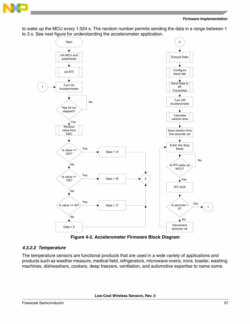
to wake up the MCU every 1.024 s. The random number permits sending the data in a range between 1 to 3 s. See next figure for understanding the accelerometer application.
Figure 4-2. Accelerometer Firmware Block Diagram
4.3.2.2 Temperature
The temperature sensors are functional products that are used in a wide variety of applications and products such as weather measure, medical field, refrigerators, microwave ovens, irons, toaster, washing machines, dishwashers, cookers, deep freezers, ventilation, and automotive expertise to name some.
Start
Init MCU and peripherals
Turn On Accelerometer
Has 24 ms elapsed?
No
Receive value from
ADC
Yes
Is value >= 203?
Is value >= 150?
Is value >= 40?
No
No
No
Yes
Yes
Yes
Data = ‘A’
Data = ‘B’
Data = ‘C’
Data = 0
2
Init RTI
1
Encrypt Data
Configure baud rate
Send Data to RF
Transmitter
Turn Off Accelerometer
Calculate random time
Save random time into seconds var
Enter into Stop Mode
Is seconds = 0? 1
Yes
No
Decrement seconds var
Is RTI wake up MCU?
No
Yes
RTI ACK
2
Firmware Description
Low-Cost Wireless Sensors, Rev. 0
58 Freescale Semiconductor
The temperature wireless sensor has some excellent features for small applications that need the temperature measure.
It is important to know the temperature range measure of these wireless sensors are from -8°C to 80°C. These sensors ensure a correct functionality within this range.
For this wireless sensor application it is important to include the TangoDriver.asm and the ADCdriver.asm files as in the accelerometer application. The TangoDriver.asm provides all the necessary resources to send encrypted data via wireless. The ADCdriver.asm contains the capability to read an analog value that comes from the thermistor voltage.
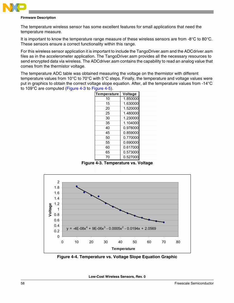
The temperature ADC table was obtained measuring the voltage on the thermistor with different temperature values from 10°C to 70°C with 5°C steps. Finally, the temperature and voltage values were put in graphics to obtain the correct voltage slope equation. After, all the temperature values from -14°C to 109°C are computed (Figure 4-3 to Figure 4-5).
Figure 4-3. Temperature vs. Voltage
Figure 4-4. Temperature vs. Voltage Slope Equation Graphic
Temperature Voltage10 1.85000015 1.63000020 1.52000025 1.48000030 1.23000035 1.10400040 0.97800045 0.85900050 0.77000055 0.69000060 0.61700065 0.57300070 0.527000
y = -4E-08x4 + 9E-06x3 - 0.0005x2 - 0.0194x + 2.0569
00.20.40.60.8
11.21.41.61.8
2
0 10 20 30 40 50 60 70 80
Temperature
Volta
ge
Firmware Implementation
Low-Cost Wireless Sensors, Rev. 0
Freescale Semiconductor 59
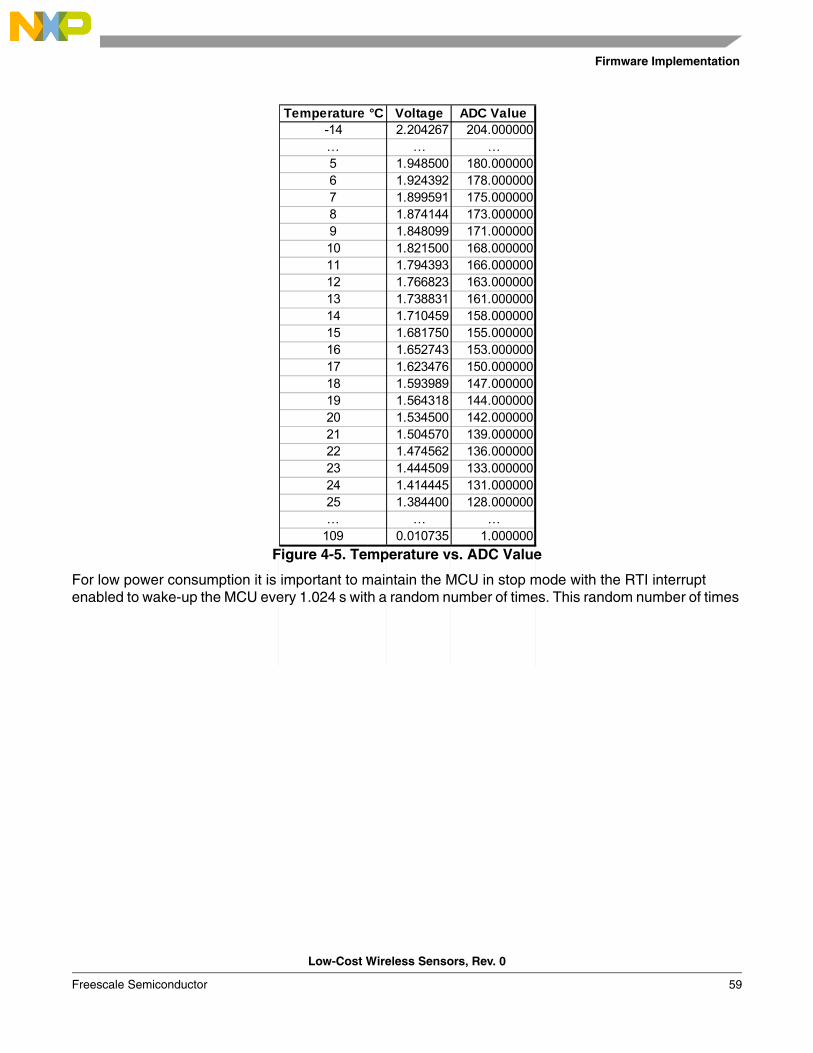
Figure 4-5. Temperature vs. ADC Value
For low power consumption it is important to maintain the MCU in stop mode with the RTI interrupt enabled to wake-up the MCU every 1.024 s with a random number of times. This random number of times
Temperature °C Voltage ADC Value-14 2.204267 204.000000… … …5 1.948500 180.0000006 1.924392 178.0000007 1.899591 175.0000008 1.874144 173.0000009 1.848099 171.00000010 1.821500 168.00000011 1.794393 166.00000012 1.766823 163.00000013 1.738831 161.00000014 1.710459 158.00000015 1.681750 155.00000016 1.652743 153.00000017 1.623476 150.00000018 1.593989 147.00000019 1.564318 144.00000020 1.534500 142.00000021 1.504570 139.00000022 1.474562 136.00000023 1.444509 133.00000024 1.414445 131.00000025 1.384400 128.000000… … …
109 0.010735 1.000000
Firmware Description
Low-Cost Wireless Sensors, Rev. 0
60 Freescale Semiconductor
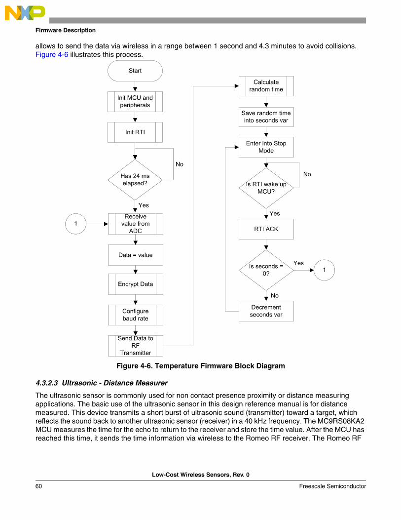
allows to send the data via wireless in a range between 1 second and 4.3 minutes to avoid collisions. Figure 4-6 illustrates this process.
Figure 4-6. Temperature Firmware Block Diagram
4.3.2.3 Ultrasonic - Distance Measurer
The ultrasonic sensor is commonly used for non contact presence proximity or distance measuring applications. The basic use of the ultrasonic sensor in this design reference manual is for distance measured. This device transmits a short burst of ultrasonic sound (transmitter) toward a target, which reflects the sound back to another ultrasonic sensor (receiver) in a 40 kHz frequency. The MC9RS08KA2 MCU measures the time for the echo to return to the receiver and store the time value. After the MCU has reached this time, it sends the time information via wireless to the Romeo RF receiver. The Romeo RF
Encrypt Data
Configure baud rate
Send Data to RF
Transmitter
Start
Init MCU and peripherals
Init RTI
Receive value from
ADC
Data = value
1
Calculate random time
Save random time into seconds var
Enter into Stop Mode
Is seconds = 0? 1
Yes
No
Decrement seconds var
Is RTI wake up MCU?
No
Yes
RTI ACK
Has 24 ms elapsed?
No
Yes
Firmware Implementation
Low-Cost Wireless Sensors, Rev. 0
Freescale Semiconductor 61
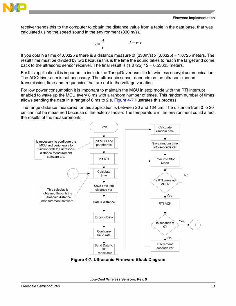
receiver sends this to the computer to obtain the distance value from a table in the data base, that was calculated using the speed sound in the environment (330 m/s).
If you obtain a time of .00325 s there is a distance measure of (330m/s) x (.00325) = 1.0725 meters. The result time must be divided by two because this is the time the sound takes to reach the target and come back to the ultrasonic sensor receiver. The final result is (1.0725) / 2 = 0.53625 meters.
For this application it is important to include the TangoDriver.asm file for wireless encrypt communication. The ADCdriver.asm is not necessary. The ultrasonic sensor depends on the ultrasonic sound transmission, time and frequencies that are not in the voltage variation.
For low power consumption it is important to maintain the MCU in stop mode with the RTI interrupt enabled to wake up the MCU every 8 ms with a random number of times. This random number of times allows sending the data in a range of 8 ms to 2 s. Figure 4-7 illustrates this process.
The range distance measured for this application is between 20 and 124 cm. The distance from 0 to 20 cm can not be measured because of the external noise. The temperature in the environment could affect the results of the measurements.
Figure 4-7. Ultrasonic Firmware Block Diagram
tdv = tvd ⋅=
Start
Init MCU and peripherals
Init RTI
Calculate time
Save time into distance var
Data = distance
This calculus is obtained through the ultrasonic distance
measurement software.
Encrypt Data
Configure baud rate
Send Data to RF
Transmitter
Calculate random time
Save random time into seconds var
Enter into Stop Mode
Is seconds = 0? 1
Yes
No
Decrement seconds var
Is RTI wake up MCU?
No
Yes
RTI ACK
1
Is necessary to configure the MCU and peripherals to
function with the ultrasonic distance measurement
software too.
Firmware Description
Low-Cost Wireless Sensors, Rev. 0
62 Freescale Semiconductor
4.3.2.4 Pressure
A pressure sensor measures the pressure of gases or fluids. Pressure is an expression of force required to stop a gas or liquid from expanding. The main utility of pressure sensors are to monitor the pressure of fluids. In comparison with flow sensors, pressure sensors are cheaper. There are two major categories of pressure sensor applications: pressure sensing and altitude sensing. Some pressure sensing applications are weather instruments, gas pumps, cars. Some altitude sensing applications are aircraft, rockets, and satellites.
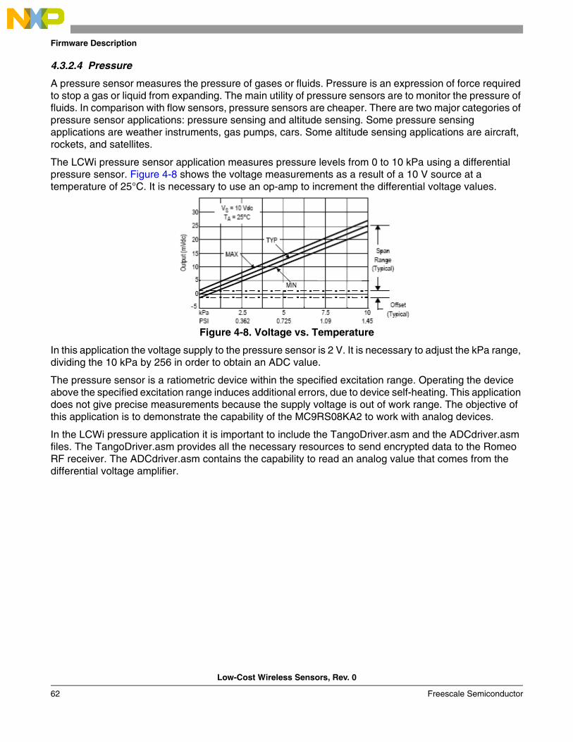
The LCWi pressure sensor application measures pressure levels from 0 to 10 kPa using a differential pressure sensor. Figure 4-8 shows the voltage measurements as a result of a 10 V source at a temperature of 25°C. It is necessary to use an op-amp to increment the differential voltage values.
Figure 4-8. Voltage vs. Temperature
In this application the voltage supply to the pressure sensor is 2 V. It is necessary to adjust the kPa range, dividing the 10 kPa by 256 in order to obtain an ADC value.
The pressure sensor is a ratiometric device within the specified excitation range. Operating the device above the specified excitation range induces additional errors, due to device self-heating. This application does not give precise measurements because the supply voltage is out of work range. The objective of this application is to demonstrate the capability of the MC9RS08KA2 to work with analog devices.
In the LCWi pressure application it is important to include the TangoDriver.asm and the ADCdriver.asm files. The TangoDriver.asm provides all the necessary resources to send encrypted data to the Romeo RF receiver. The ADCdriver.asm contains the capability to read an analog value that comes from the differential voltage amplifier.
Firmware Implementation
Low-Cost Wireless Sensors, Rev. 0
Freescale Semiconductor 63
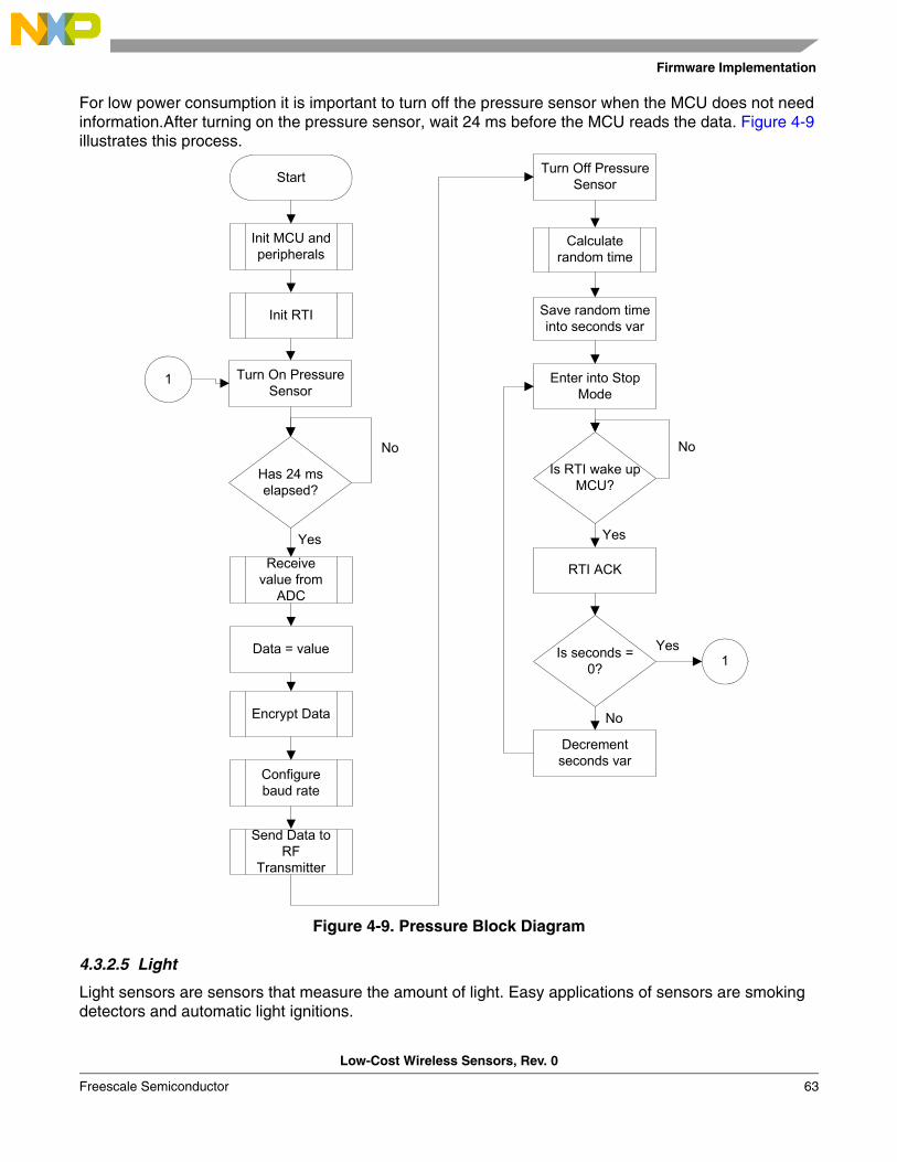
For low power consumption it is important to turn off the pressure sensor when the MCU does not need information.After turning on the pressure sensor, wait 24 ms before the MCU reads the data. Figure 4-9 illustrates this process.
Figure 4-9. Pressure Block Diagram
4.3.2.5 Light
Light sensors are sensors that measure the amount of light. Easy applications of sensors are smoking detectors and automatic light ignitions.
Encrypt Data
Configure baud rate
Send Data to RF
Transmitter
Start
Init MCU and peripherals
Init RTI
Receive value from
ADC
Data = value
Calculate random time
Save random time into seconds var
Enter into Stop Mode
Is seconds = 0? 1
Yes
No
Decrement seconds var
Is RTI wake up MCU?
No
Yes
RTI ACK
Turn On Pressure Sensor
Has 24 ms elapsed?
No
Yes
1
Turn Off Pressure Sensor

Firmware Description
Low-Cost Wireless Sensors, Rev. 0
64 Freescale Semiconductor
In the LCWi application the sensor used measures three different ranges of light, high, medium and low intensities.
It is necessary to include the TangoDriver.asm and ADCdriver.asm files. The TangoDriver.asm file contains everything required to send encrypted data to the Romeo RF receiver via wireless. The ADCdriver.asm file has the capability to read an analog value from the photoresistor and convert it to a digital 8-bit number, 0-255. The value obtained from the photoresistor could be anything within the three ranges of light intensity. This depends on the light in the environment. If the ADC obtains a value from 150 up to 255 (1.62 V– 2.753 V) the light intensity is low; if the ADC value is between 75 and 150 (0.8 V– 1.62 V) the light intensity is medium; but if the ADC has a value from 10 up to 75 (0.11 V– 0.8 V) this means the light intensity is high.
For low power consumption it is important to maintain the MCU in stop mode with the RTI interrupt enabled to wake up the MCU every 1.024 s with a random number of times. This random number of times allows sending data in a range of 1 s to 1 min. Figure 4-10 illustrates the process.
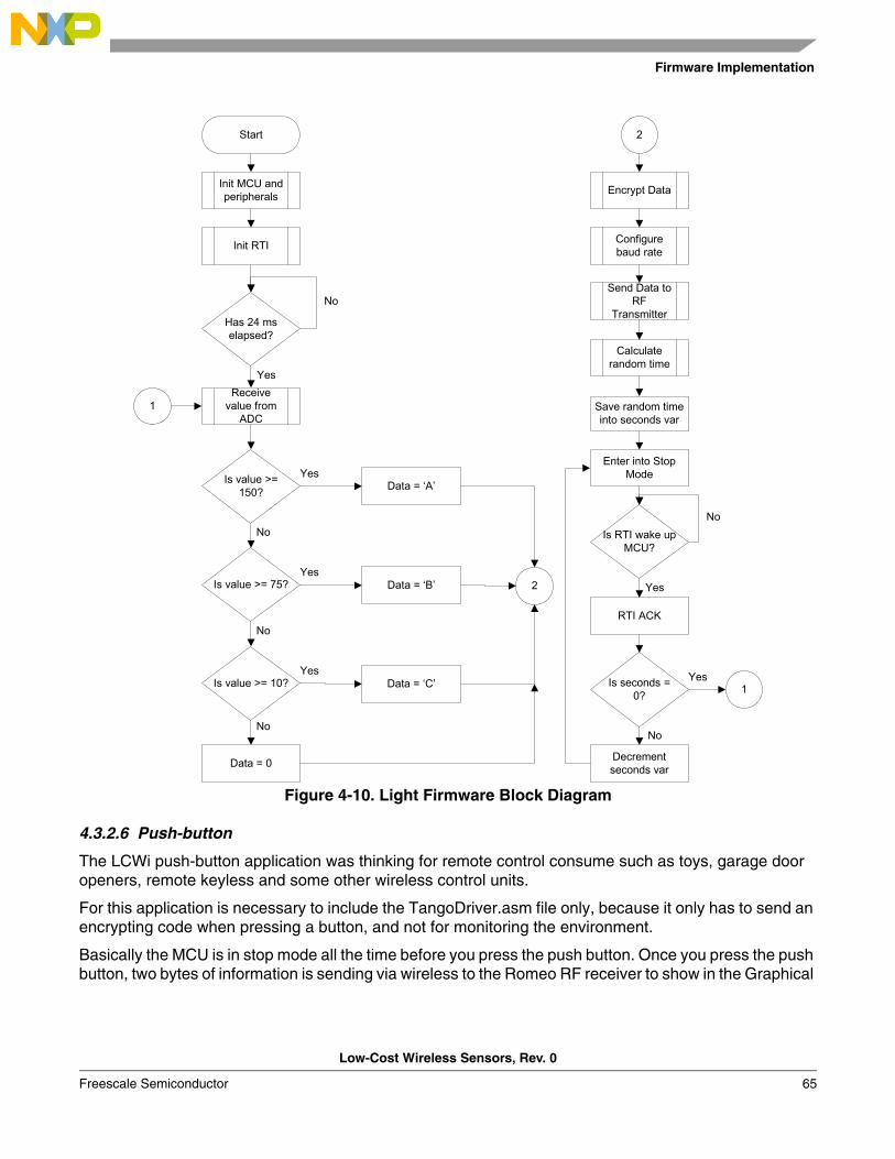
Firmware Implementation
Low-Cost Wireless Sensors, Rev. 0
Freescale Semiconductor 65
Figure 4-10. Light Firmware Block Diagram
4.3.2.6 Push-button
The LCWi push-button application was thinking for remote control consume such as toys, garage door openers, remote keyless and some other wireless control units.
For this application is necessary to include the TangoDriver.asm file only, because it only has to send an encrypting code when pressing a button, and not for monitoring the environment.
Basically the MCU is in stop mode all the time before you press the push button. Once you press the push button, two bytes of information is sending via wireless to the Romeo RF receiver to show in the Graphical
Start
Init MCU and peripherals
Has 24 ms elapsed?
No
Receive value from
ADC
Yes
Is value >= 150?
Is value >= 75?
Is value >= 10?
No
No
No
Yes
Yes
Yes
Data = ‘A’
Data = ‘B’
Data = ‘C’
Data = 0
2
Init RTI
1
Encrypt Data
Configure baud rate
Send Data to RF
Transmitter
Calculate random time
Save random time into seconds var
Enter into Stop Mode
Is seconds = 0? 1
Yes
No
Decrement seconds var
Is RTI wake up MCU?
No
Yes
RTI ACK
2
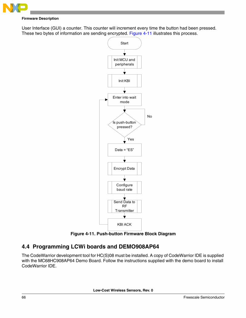
Firmware Description
Low-Cost Wireless Sensors, Rev. 0
66 Freescale Semiconductor
User Interface (GUI) a counter. This counter will increment every time the button had been pressed. These two bytes of information are sending encrypted. Figure 4-11 illustrates this process.
Figure 4-11. Push-button Firmware Block Diagram
4.4 Programming LCWi boards and DEMO908AP64
The CodeWarrior development tool for HC(S)08 must be installed. A copy of CodeWarrior IDE is supplied with the MC68HC908AP64 Demo Board. Follow the instructions supplied with the demo board to install CodeWarrior IDE.
Start
Init MCU andperipherals
Init KBI
Enter into waitmode
Is push-buttonpressed?
No
Data = “ES”
Yes
Encrypt Data
Configurebaud rate
Send Data toRF
Transmitter
KBI ACK

Programming LCWi boards and DEMO908AP64
Low-Cost Wireless Sensors, Rev. 0
Freescale Semiconductor 67
4.4.1 Programming LCWi boards
4.4.1.1 Programming the Firmware
For programming the LCWi boards it is necessary to follow the next steps:1. Open CodeWarrior integrated development environment (IDE) version 5.1.2. Open the application.mcp file from the TANGOKA2SW/Sensors Applications/Application folder.3. Change the MCU connections to P&E Multilink/Cyclone Pro.4. Remove all jumpers from the boards.5. Press the F7 function key for making the project.6. Connect a 3.3 V power supply or battery to the power connectors on the boards.7. Press the F5 function key to download the file into the flash memory.8. In the ICD – Connection Manager window configuration, select USB HCS08/HCS12 Multilink (Rev
C or Later) as an interface and press the Connect button. 9. When the CodeWarrior compiler asks to write into the flash memory, click on the yes button.
10. Finally the CodeWarrior compiler starts to download the file into the flash.
NOTEIf any problem occurs when trying to write into the flash memory, turn off the power supply. Turn it on again and at the same time press the Connect button again.
4.4.1.2 Using the Firmware
For using the firmware the jumpers must be place on the boards, except the Ultrasonic sensor board. For the ultrasonic sensor board place jumpers J2 and J5 only.
4.4.2 Programming DEMO908AP64
4.4.2.1 Programming the Firmware
If the RomeoAP64 has already been programmed into the MC68HC908AP64 Demo Board, the user can begin to use the Romeo RF Transmitter. To program the Romeo AP64:
1. Install power select PWR_SEL jumpers 1 and 2 on the MC68HC908AP64 Demo Board.2. Install VST_EN jumper.3. Install MON_EN jumper.4. Select setting DEBUG on COM_SEL header.5. Install jumper across pins 1 and 2 of header OSC_SEL.6. Install all USER_EN jumpers.7. Connect the serial port connector on the MC68HC908AP64 Demo Board to a PC comm. port using
a 9-pin straight-through serial cable.8. Connect a 9 V power supply or battery to the power connector of the MC68HC908AP64 board.9. Unzip file RomeoAP64.zip, which is contained within the TANGOKA2SW.zip. This unzips a
CodeWarrior project containing the programming file for the application.10. Start CodeWarrior IDE.11. Select File/Open and open the file RomeoAP64.mcp. This opens a CodeWarrior project.12. In CodeWarrior IDE, click on file RomeoAP64 in the Target window. Then press key F5 or select

Firmware Description
Low-Cost Wireless Sensors, Rev. 0
68 Freescale Semiconductor
Project/Debug from the menu bar. This launches the debugger, which communicates with the MC68HC908AP64 Demo Board and attempts to burn the Romeo RF Receiver program into FLASH memory on the MCU. The Attempting to contact target and pass security window should appear. Make sure the following options are configured correctly.a. Target Hardware Type: Class 3.
b. Serial Port: 1 this depends on the PC COM Port.
c. Baud: 19200 baud rate.
d. Target MCU security bytes: Check the, IGNORE security failure and enter monitor mode, check box.
13. Click the Contact target with these settings button and follow the instructions on the screen. When the, Erase and Program Flash? window, appears, click the Yes button.
14. Follow the on-screen instructions for cycling the MCU power supply. The CPROG08SZ Programmer window should close after the MCU FLASH is programmed.
15. The Romeo RF Transmitter program has now been programmed into the FLASH memory of the MC68HC908AP64. CodeWarrior IDE is no longer required. Shut all CodeWarrior windows and exit the program.
4.4.3 Setting the Romeo RF Receiver
To use the Romeo RF Receiver, the hardware must be set up as follows:
NOTERomeo2 RF modules are available in a range of frequencies, each is supplied with an appropriate antenna.
1. Connect the Romeo2 RF Module to connector J1 on the MC68HC908AP64 Demo Board. Pin 1 on each board must be aligned.
2. Connect an antenna to the Romeo2 RF module.3. Install power select PWR_SEL jumpers 1 and 2 on the MC68HC908AP64 Demo Board. Both
jumpers must be installed.4. Remove VST_EN jumper.5. Remove MON_EN jumper.6. Install jumper across pins 1 and 2 of header OSC_SEL.7. Install jumper on COM setting of COM_SEL header.8. Install all USER_EN jumpers.9. Connect the serial port connector on the MC68HC908AP64 Demo Board to a PC comm. port using
a 9-pin straight-through serial cable.10. Connect a 9 V power supply or battery to power connector on MC68HC908AP64 board.
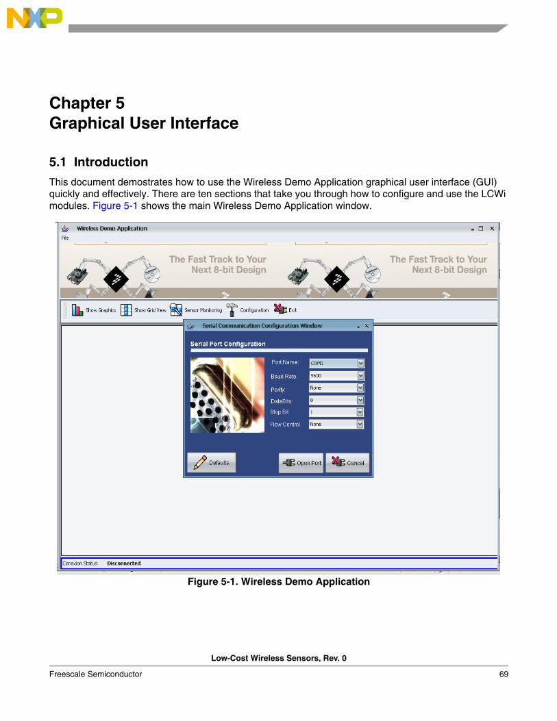
Low-Cost Wireless Sensors, Rev. 0
Freescale Semiconductor 69
Chapter 5 Graphical User Interface
5.1 Introduction
This document demostrates how to use the Wireless Demo Application graphical user interface (GUI) quickly and effectively. There are ten sections that take you through how to configure and use the LCWi modules. Figure 5-1 shows the main Wireless Demo Application window.
Figure 5-1. Wireless Demo Application
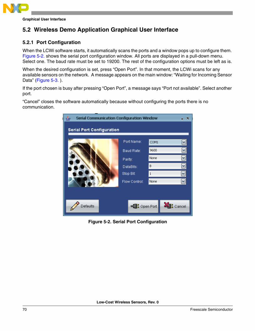
Graphical User Interface
Low-Cost Wireless Sensors, Rev. 0
70 Freescale Semiconductor
5.2 Wireless Demo Application Graphical User Interface
5.2.1 Port Configuration
When the LCWi software starts, it automatically scans the ports and a window pops up to configure them. Figure 5-2. shows the serial port configuration window. All ports are displayed in a pull-down menu. Select one. The baud rate must be set to 19200. The rest of the configuration options must be left as is.
When the desired configuration is set, press “Open Port”. In that moment, the LCWi scans for any available sensors on the network. A message appears on the main window: “Waiting for Incoming Sensor Data” (Figure 5-3. ).
If the port chosen is busy after pressing “Open Port”, a message says “Port not available”. Select another port.
“Cancel” closes the software automatically because without configuring the ports there is no communication.
Figure 5-2. Serial Port Configuration
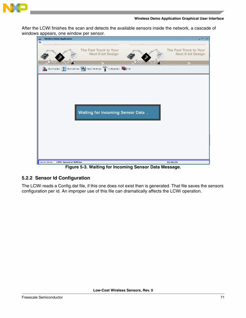
Wireless Demo Application Graphical User Interface
Low-Cost Wireless Sensors, Rev. 0
Freescale Semiconductor 71
After the LCWi finishes the scan and detects the available sensors inside the network, a cascade of windows appears, one window per sensor.
Figure 5-3. Waiting for Incoming Sensor Data Message.
5.2.2 Sensor Id Configuration
The LCWi reads a Config.dat file, if this one does not exist then is generated. That file saves the sensors configuration per id. An improper use of this file can dramatically affects the LCWi operation.
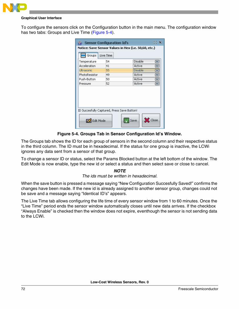
Graphical User Interface
Low-Cost Wireless Sensors, Rev. 0
72 Freescale Semiconductor
To configure the sensors click on the Configuration button in the main menu. The configuration window has two tabs: Groups and Live Time (Figure 5-4).
Figure 5-4. Groups Tab in Sensor Configuration Id’s Window.
The Groups tab shows the ID for each group of sensors in the second column and their respective status in the third column. The ID must be in hexadecimal. If the status for one group is inactive, the LCWi ignores any data sent from a sensor of that group.
To change a sensor ID or status, select the Params Blocked button at the left bottom of the window. The Edit Mode is now enable, type the new id or select a status and then select save or close to cancel.
NOTEThe ids must be written in hexadecimal.
When the save button is pressed a message saying “New Configuration Succesfully Saved!” confirms the changes have been made. If the new id is already assigned to another sensor group, changes could not be save and a message saying “Identical ID’s” appears.
The Live Time tab allows configuring the life time of every sensor window from 1 to 60 minutes. Once the “Live Time” period ends the sensor window automatically closes until new data arrives. If the checkbox “Always Enable” is checked then the window does not expire, eventhough the sensor is not sending data to the LCWi.
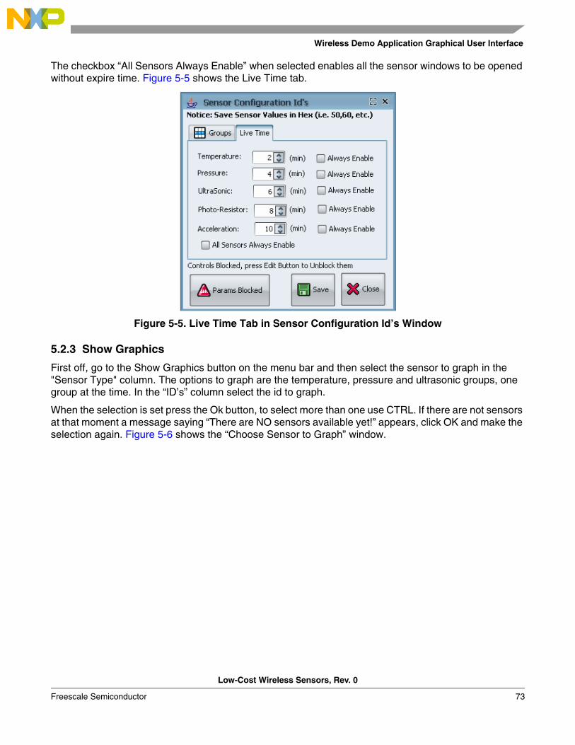
Wireless Demo Application Graphical User Interface
Low-Cost Wireless Sensors, Rev. 0
Freescale Semiconductor 73
The checkbox “All Sensors Always Enable” when selected enables all the sensor windows to be opened without expire time. Figure 5-5 shows the Live Time tab.
Figure 5-5. Live Time Tab in Sensor Configuration Id’s Window
5.2.3 Show Graphics
First off, go to the Show Graphics button on the menu bar and then select the sensor to graph in the "Sensor Type" column. The options to graph are the temperature, pressure and ultrasonic groups, one group at the time. In the “ID’s” column select the id to graph.
When the selection is set press the Ok button, to select more than one use CTRL. If there are not sensors at that moment a message saying “There are NO sensors available yet!” appears, click OK and make the selection again. Figure 5-6 shows the “Choose Sensor to Graph” window.
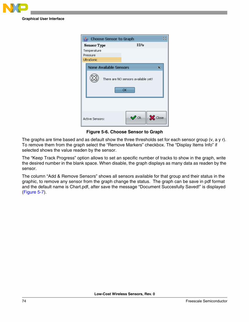
Graphical User Interface
Low-Cost Wireless Sensors, Rev. 0
74 Freescale Semiconductor
Figure 5-6. Choose Sensor to Graph
The graphs are time based and as default show the three thresholds set for each sensor group (v, a y r). To remove them from the graph select the “Remove Markers” checkbox. The “Display Items Info” if selected shows the value readen by the sensor.
The “Keep Track Progress” option allows to set an specific number of tracks to show in the graph, write the desired number in the blank space. When disable, the graph displays as many data as readen by the sensor.
The column “Add & Remove Sensors” shows all sensors available for that group and their status in the graphic, to remove any sensor from the graph change the status. The graph can be save in pdf format and the default name is Chart.pdf, after save the message “Document Succesfully Saved!” is displayed (Figure 5-7).
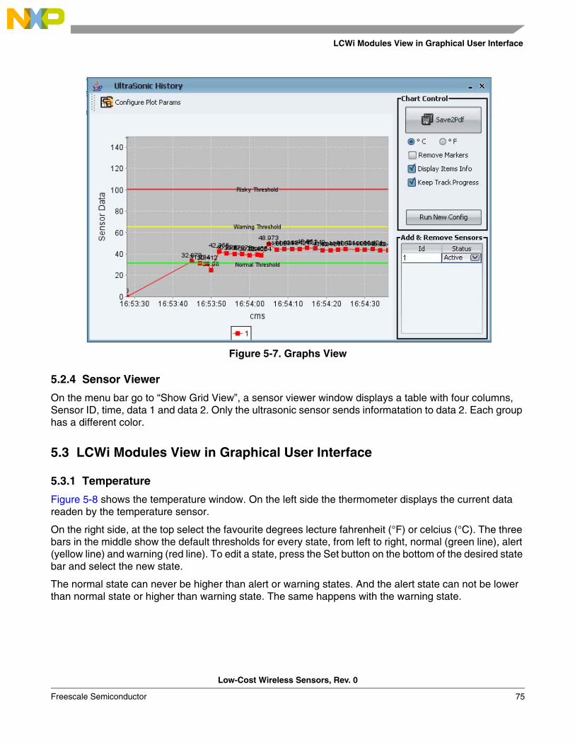
LCWi Modules View in Graphical User Interface
Low-Cost Wireless Sensors, Rev. 0
Freescale Semiconductor 75
Figure 5-7. Graphs View
5.2.4 Sensor Viewer
On the menu bar go to “Show Grid View”, a sensor viewer window displays a table with four columns, Sensor ID, time, data 1 and data 2. Only the ultrasonic sensor sends informatation to data 2. Each group has a different color.
5.3 LCWi Modules View in Graphical User Interface
5.3.1 Temperature
Figure 5-8 shows the temperature window. On the left side the thermometer displays the current data readen by the temperature sensor.
On the right side, at the top select the favourite degrees lecture fahrenheit (°F) or celcius (°C). The three bars in the middle show the default thresholds for every state, from left to right, normal (green line), alert (yellow line) and warning (red line). To edit a state, press the Set button on the bottom of the desired state bar and select the new state.
The normal state can never be higher than alert or warning states. And the alert state can not be lower than normal state or higher than warning state. The same happens with the warning state.
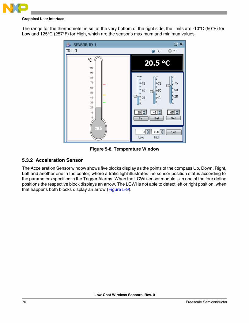
Graphical User Interface
Low-Cost Wireless Sensors, Rev. 0
76 Freescale Semiconductor
The range for the thermometer is set at the very bottom of the right side, the limits are -10°C (50°F) for Low and 125°C (257°F) for High, which are the sensor’s maximum and minimun values.
Figure 5-8. Temperature Window
5.3.2 Acceleration Sensor
The Acceleration Sensor window shows five blocks display as the points of the compass Up, Down, Right, Left and another one in the center, where a trafic light illustrates the sensor position status according to the parameters specified in the Trigger Alarms. When the LCWi sensor module is in one of the four define positions the respective block displays an arrow. The LCWi is not able to detect left or right position, when that happens both blocks display an arrow (Figure 5-9).
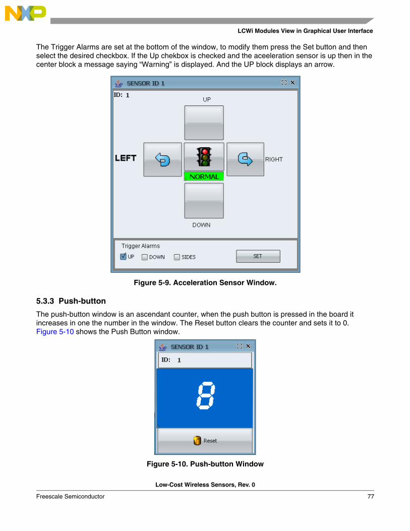
LCWi Modules View in Graphical User Interface
Low-Cost Wireless Sensors, Rev. 0
Freescale Semiconductor 77
The Trigger Alarms are set at the bottom of the window, to modify them press the Set button and then select the desired checkbox. If the Up chekbox is checked and the aceeleration sensor is up then in the center block a message saying “Warning” is displayed. And the UP block displays an arrow.
Figure 5-9. Acceleration Sensor Window.
5.3.3 Push-button
The push-button window is an ascendant counter, when the push button is pressed in the board it increases in one the number in the window. The Reset button clears the counter and sets it to 0. Figure 5-10 shows the Push Button window.
Figure 5-10. Push-button Window
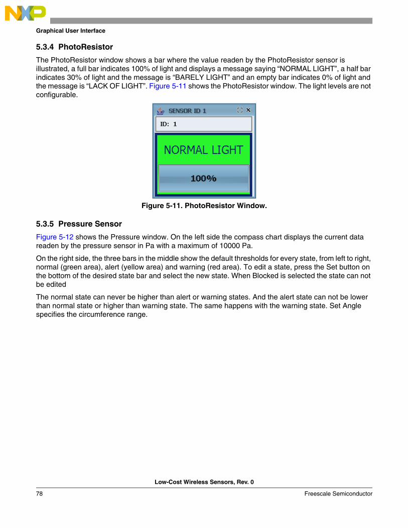
Graphical User Interface
Low-Cost Wireless Sensors, Rev. 0
78 Freescale Semiconductor
5.3.4 PhotoResistor
The PhotoResistor window shows a bar where the value readen by the PhotoResistor sensor is illustrated, a full bar indicates 100% of light and displays a message saying “NORMAL LIGHT”, a half bar indicates 30% of light and the message is “BARELY LIGHT” and an empty bar indicates 0% of light and the message is “LACK OF LIGHT”. Figure 5-11 shows the PhotoResistor window. The light levels are not configurable.
Figure 5-11. PhotoResistor Window.
5.3.5 Pressure Sensor
Figure 5-12 shows the Pressure window. On the left side the compass chart displays the current data readen by the pressure sensor in Pa with a maximum of 10000 Pa.
On the right side, the three bars in the middle show the default thresholds for every state, from left to right, normal (green area), alert (yellow area) and warning (red area). To edit a state, press the Set button on the bottom of the desired state bar and select the new state. When Blocked is selected the state can not be edited
The normal state can never be higher than alert or warning states. And the alert state can not be lower than normal state or higher than warning state. The same happens with the warning state. Set Angle specifies the circumference range.
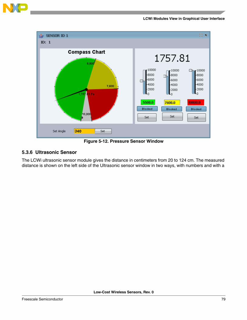
LCWi Modules View in Graphical User Interface
Low-Cost Wireless Sensors, Rev. 0
Freescale Semiconductor 79
Figure 5-12. Pressure Sensor Window
5.3.6 Ultrasonic Sensor
The LCWi ultrasonic sensor module gives the distance in centimeters from 20 to 124 cm. The measured distance is shown on the left side of the Ultrasonic sensor window in two ways, with numbers and with a

Graphical User Interface
Low-Cost Wireless Sensors, Rev. 0
80 Freescale Semiconductor
percentage represented in a bar. Upper and lower limits can be configured on the right side of the window (Figure 5-13).
Figure 5-13. Ultrasonic Sensor Window
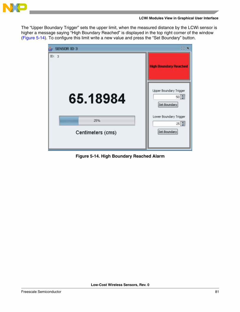
LCWi Modules View in Graphical User Interface
Low-Cost Wireless Sensors, Rev. 0
Freescale Semiconductor 81
The “Upper Boundary Trigger” sets the upper limit, when the measured distance by the LCWi sensor is higher a message saying “High Boundary Reached” is displayed in the top right corner of the window (Figure 5-14). To configure this limit write a new value and press the “Set Boundary” button.
Figure 5-14. High Boundary Reached Alarm
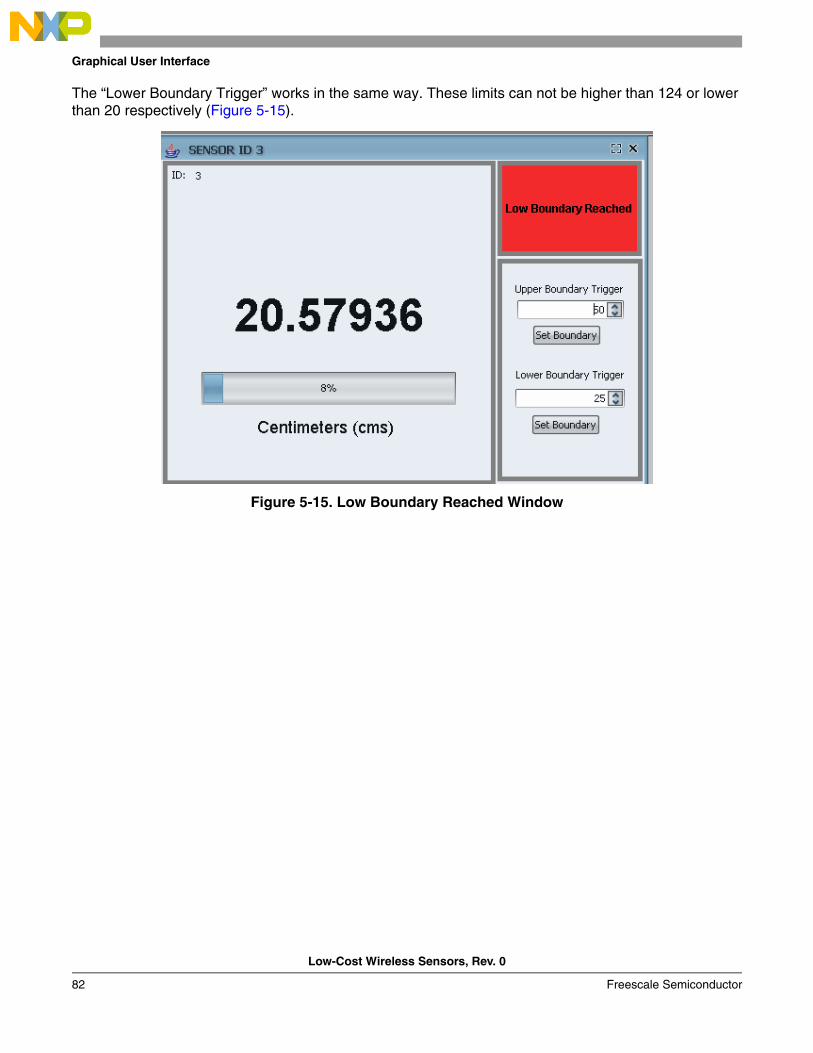
Graphical User Interface
Low-Cost Wireless Sensors, Rev. 0
82 Freescale Semiconductor
The “Lower Boundary Trigger” works in the same way. These limits can not be higher than 124 or lower than 20 respectively (Figure 5-15).
Figure 5-15. Low Boundary Reached Window
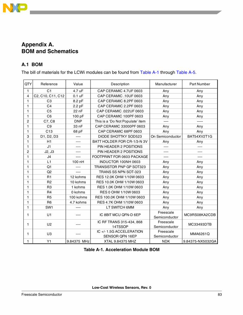
Low-Cost Wireless Sensors, Rev. 0
Freescale Semiconductor 83
Appendix A. BOM and Schematics
A.1 BOM
The bill of materials for the LCWi modules can be found from Table A-1 through Table A-5.
Table A-1. Acceleration Module BOM
QTY Reference Value Description Manufacturer Part Number
1 C1 4.7 uF CAP CERAMIC 4.7UF 0603 Any Any4 C2, C10, C11, C12 0.1 uF CAP CERAMIC .10UF 0603 Any Any1 C3 8.2 pF CAP CERAMIC 8.2PF 0603 Any Any1 C4 2.2 pF CAP CERAMIC 2.2PF 0603 Any Any1 C5 22 nF CAP CERAMIC .022UF 0603 Any Any1 C6 100 pF CAP CERAMIC 100PF 0603 Any Any2 C7, C8 DNP This is a ‘Do Not Populate’ item ---- -----1 C9 33 nF CAP CERAMIC 33000PF 0603 Any Any1 C13 68 pF CAP CERAMIC 68PF 0603 Any Any3 D1, D2, D3 ---- DIODE SHOTTKY SOD523 On Semiconductor BAT54XV2T1G1 H1 ---- BATT HOLDER FOR CR-1/3-N 3V Any Any1 J1 ---- PIN HEADER 2 POSITIONS ---- ----2 J2, J3 ---- PIN HEADER 2 POSITIONS ---- ----1 J4 ---- FOOTPRINT FOR 0603 PACKAGE ---- ----1 L1 100 nH INDUCTOR 100NH 0603 Any Any1 Q1 ---- TRANSISTOR PNP GP SOT323 Any Any1 Q2 ---- TRANS SS NPN SOT-323 Any Any1 R1 12 kohms RES 12.0K OHM 1/10W 0603 Any Any1 R2 10 kohms RES 10.0K OHM 1/10W 0603 Any Any1 R3 1 kohms RES 1.0K OHM 1/10W 0603 Any Any1 R4 0 kohms RES 0 OHM 1/10W 0603 Any Any1 R5 100 kohms RES 100.0K OHM 1/10W 0603 Any Any1 R6 4.7 kohms RES 4.7K OHM 1/10W 0603 Any Any1 SW1 ---- LT SWITCH 6MM Any Any
1 U1 ---- IC 8BIT MCU QFN-D 6EPFreescale
SemiconductorMC9RS08KA2CDB
1 U2 ----IC RF TRANS 315-434, 868
14TSSOPFreescale
SemiconductorMC33493DTB
1 U3 ----IC +/- 1.5G ACCELERATION
SENSOR QFN 16EPFreescale
SemiconductorMMA6261Q
1 Y1 9.84375 MHz XTAL 9.84375 MHZ NDK 9.84375-NX5032GA
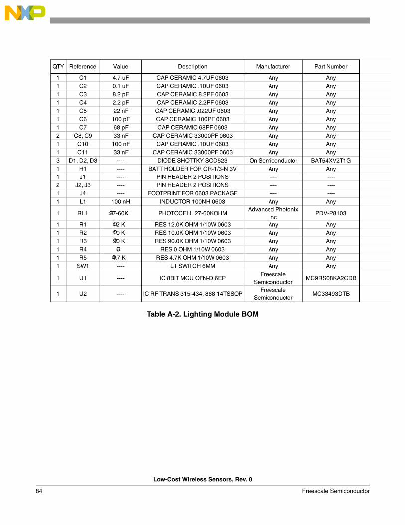
Low-Cost Wireless Sensors, Rev. 0
84 Freescale Semiconductor
Table A-2. Lighting Module BOM
QTY Reference Value Description Manufacturer Part Number
1 C1 4.7 uF CAP CERAMIC 4.7UF 0603 Any Any1 C2 0.1 uF CAP CERAMIC .10UF 0603 Any Any1 C3 8.2 pF CAP CERAMIC 8.2PF 0603 Any Any1 C4 2.2 pF CAP CERAMIC 2.2PF 0603 Any Any1 C5 22 nF CAP CERAMIC .022UF 0603 Any Any1 C6 100 pF CAP CERAMIC 100PF 0603 Any Any1 C7 68 pF CAP CERAMIC 68PF 0603 Any Any2 C8, C9 33 nF CAP CERAMIC 33000PF 0603 Any Any1 C10 100 nF CAP CERAMIC .10UF 0603 Any Any1 C11 33 nF CAP CERAMIC 33000PF 0603 Any Any3 D1, D2, D3 ---- DIODE SHOTTKY SOD523 On Semiconductor BAT54XV2T1G1 H1 ---- BATT HOLDER FOR CR-1/3-N 3V Any Any1 J1 ---- PIN HEADER 2 POSITIONS ---- ----2 J2, J3 ---- PIN HEADER 2 POSITIONS ---- ----1 J4 ---- FOOTPRINT FOR 0603 PACKAGE ---- ----1 L1 100 nH INDUCTOR 100NH 0603 Any Any
1 RL1 27-60KΩ PHOTOCELL 27-60KOHMAdvanced Photonix
IncPDV-P8103
1 R1 12 KΩ RES 12.0K OHM 1/10W 0603 Any Any1 R2 10 KΩ RES 10.0K OHM 1/10W 0603 Any Any1 R3 90 KΩ RES 90.0K OHM 1/10W 0603 Any Any1 R4 0 Ω RES 0 OHM 1/10W 0603 Any Any1 R5 4.7 KΩ RES 4.7K OHM 1/10W 0603 Any Any1 SW1 ---- LT SWITCH 6MM Any Any
1 U1 ---- IC 8BIT MCU QFN-D 6EPFreescale
SemiconductorMC9RS08KA2CDB
1 U2 ---- IC RF TRANS 315-434, 868 14TSSOPFreescale
SemiconductorMC33493DTB
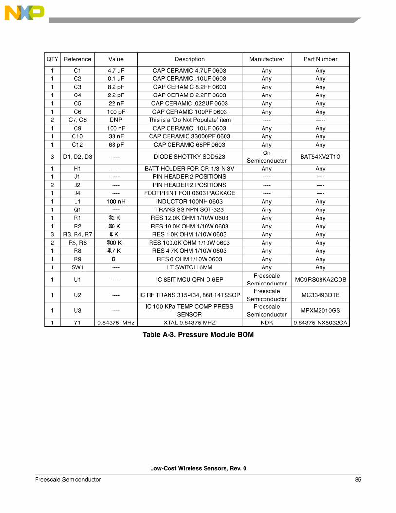
Low-Cost Wireless Sensors, Rev. 0
Freescale Semiconductor 85
Table A-3. Pressure Module BOM
QTY Reference Value Description Manufacturer Part Number
1 C1 4.7 uF CAP CERAMIC 4.7UF 0603 Any Any1 C2 0.1 uF CAP CERAMIC .10UF 0603 Any Any1 C3 8.2 pF CAP CERAMIC 8.2PF 0603 Any Any1 C4 2.2 pF CAP CERAMIC 2.2PF 0603 Any Any1 C5 22 nF CAP CERAMIC .022UF 0603 Any Any1 C6 100 pF CAP CERAMIC 100PF 0603 Any Any2 C7, C8 DNP This is a ‘Do Not Populate’ item ---- -----1 C9 100 nF CAP CERAMIC .10UF 0603 Any Any1 C10 33 nF CAP CERAMIC 33000PF 0603 Any Any1 C12 68 pF CAP CERAMIC 68PF 0603 Any Any
3 D1, D2, D3 ---- DIODE SHOTTKY SOD523On
SemiconductorBAT54XV2T1G
1 H1 ---- BATT HOLDER FOR CR-1/3-N 3V Any Any1 J1 ---- PIN HEADER 2 POSITIONS ---- ----2 J2 ---- PIN HEADER 2 POSITIONS ---- ----1 J4 ---- FOOTPRINT FOR 0603 PACKAGE ---- ----1 L1 100 nH INDUCTOR 100NH 0603 Any Any1 Q1 ---- TRANS SS NPN SOT-323 Any Any1 R1 12 KΩ RES 12.0K OHM 1/10W 0603 Any Any1 R2 10 KΩ RES 10.0K OHM 1/10W 0603 Any Any3 R3, R4, R7 1 KΩ RES 1.0K OHM 1/10W 0603 Any Any2 R5, R6 100 KΩ RES 100.0K OHM 1/10W 0603 Any Any1 R8 4.7 KΩ RES 4.7K OHM 1/10W 0603 Any Any1 R9 0 Ω RES 0 OHM 1/10W 0603 Any Any1 SW1 ---- LT SWITCH 6MM Any Any
1 U1 ---- IC 8BIT MCU QFN-D 6EPFreescale
SemiconductorMC9RS08KA2CDB
1 U2 ---- IC RF TRANS 315-434, 868 14TSSOPFreescale
SemiconductorMC33493DTB
1 U3 ----IC 100 KPa TEMP COMP PRESS
SENSORFreescale
SemiconductorMPXM2010GS
1 Y1 9.84375 MHz XTAL 9.84375 MHZ NDK 9.84375-NX5032GA
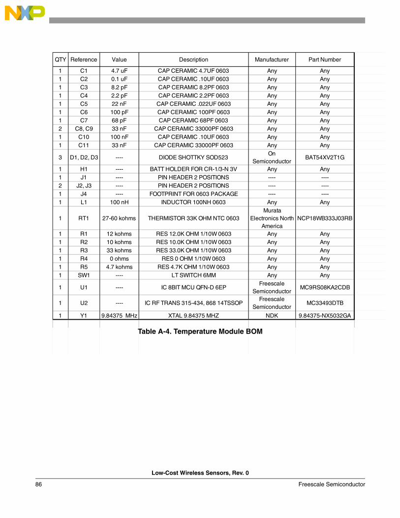
Low-Cost Wireless Sensors, Rev. 0
86 Freescale Semiconductor
Table A-4. Temperature Module BOM
QTY Reference Value Description Manufacturer Part Number
1 C1 4.7 uF CAP CERAMIC 4.7UF 0603 Any Any1 C2 0.1 uF CAP CERAMIC .10UF 0603 Any Any1 C3 8.2 pF CAP CERAMIC 8.2PF 0603 Any Any1 C4 2.2 pF CAP CERAMIC 2.2PF 0603 Any Any1 C5 22 nF CAP CERAMIC .022UF 0603 Any Any1 C6 100 pF CAP CERAMIC 100PF 0603 Any Any1 C7 68 pF CAP CERAMIC 68PF 0603 Any Any2 C8, C9 33 nF CAP CERAMIC 33000PF 0603 Any Any1 C10 100 nF CAP CERAMIC .10UF 0603 Any Any1 C11 33 nF CAP CERAMIC 33000PF 0603 Any Any
3 D1, D2, D3 ---- DIODE SHOTTKY SOD523On
SemiconductorBAT54XV2T1G
1 H1 ---- BATT HOLDER FOR CR-1/3-N 3V Any Any1 J1 ---- PIN HEADER 2 POSITIONS ---- ----2 J2, J3 ---- PIN HEADER 2 POSITIONS ---- ----1 J4 ---- FOOTPRINT FOR 0603 PACKAGE ---- ----1 L1 100 nH INDUCTOR 100NH 0603 Any Any
1 RT1 27-60 kohms THERMISTOR 33K OHM NTC 0603Murata
Electronics North America
NCP18WB333J03RB
1 R1 12 kohms RES 12.0K OHM 1/10W 0603 Any Any1 R2 10 kohms RES 10.0K OHM 1/10W 0603 Any Any1 R3 33 kohms RES 33.0K OHM 1/10W 0603 Any Any1 R4 0 ohms RES 0 OHM 1/10W 0603 Any Any1 R5 4.7 kohms RES 4.7K OHM 1/10W 0603 Any Any1 SW1 ---- LT SWITCH 6MM Any Any
1 U1 ---- IC 8BIT MCU QFN-D 6EPFreescale
SemiconductorMC9RS08KA2CDB
1 U2 ---- IC RF TRANS 315-434, 868 14TSSOPFreescale
SemiconductorMC33493DTB
1 Y1 9.84375 MHz XTAL 9.84375 MHZ NDK 9.84375-NX5032GA
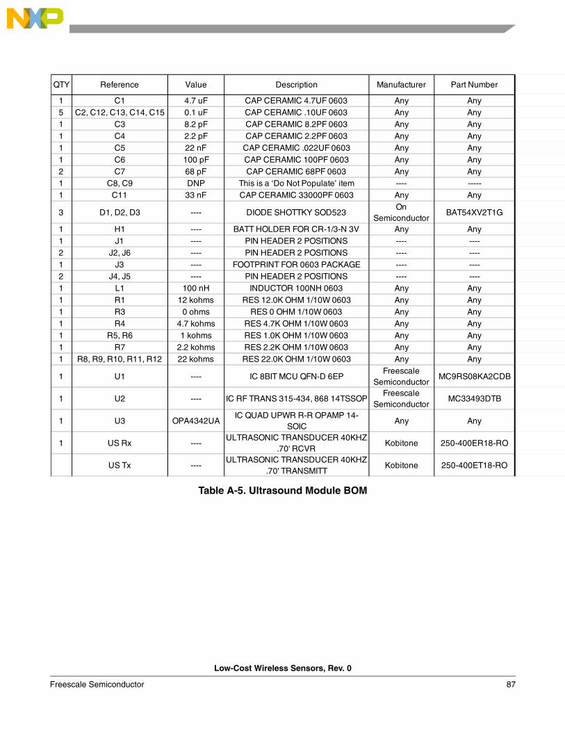
Low-Cost Wireless Sensors, Rev. 0
Freescale Semiconductor 87
Table A-5. Ultrasound Module BOM
QTY Reference Value Description Manufacturer Part Number
1 C1 4.7 uF CAP CERAMIC 4.7UF 0603 Any Any5 C2, C12, C13, C14, C15 0.1 uF CAP CERAMIC .10UF 0603 Any Any1 C3 8.2 pF CAP CERAMIC 8.2PF 0603 Any Any1 C4 2.2 pF CAP CERAMIC 2.2PF 0603 Any Any1 C5 22 nF CAP CERAMIC .022UF 0603 Any Any1 C6 100 pF CAP CERAMIC 100PF 0603 Any Any2 C7 68 pF CAP CERAMIC 68PF 0603 Any Any1 C8, C9 DNP This is a ‘Do Not Populate’ item ---- -----1 C11 33 nF CAP CERAMIC 33000PF 0603 Any Any
3 D1, D2, D3 ---- DIODE SHOTTKY SOD523On
SemiconductorBAT54XV2T1G
1 H1 ---- BATT HOLDER FOR CR-1/3-N 3V Any Any1 J1 ---- PIN HEADER 2 POSITIONS ---- ----2 J2, J6 ---- PIN HEADER 2 POSITIONS ---- ----1 J3 ---- FOOTPRINT FOR 0603 PACKAGE ---- ----2 J4, J5 ---- PIN HEADER 2 POSITIONS ---- ----1 L1 100 nH INDUCTOR 100NH 0603 Any Any1 R1 12 kohms RES 12.0K OHM 1/10W 0603 Any Any1 R3 0 ohms RES 0 OHM 1/10W 0603 Any Any1 R4 4.7 kohms RES 4.7K OHM 1/10W 0603 Any Any1 R5, R6 1 kohms RES 1.0K OHM 1/10W 0603 Any Any1 R7 2.2 kohms RES 2.2K OHM 1/10W 0603 Any Any1 R8, R9, R10, R11, R12 22 kohms RES 22.0K OHM 1/10W 0603 Any Any
1 U1 ---- IC 8BIT MCU QFN-D 6EPFreescale
SemiconductorMC9RS08KA2CDB
1 U2 ---- IC RF TRANS 315-434, 868 14TSSOPFreescale
SemiconductorMC33493DTB
1 U3 OPA4342UAIC QUAD UPWR R-R OPAMP 14-
SOICAny Any
1 US Rx ----ULTRASONIC TRANSDUCER 40KHZ
.70' RCVRKobitone 250-400ER18-RO
US Tx ----ULTRASONIC TRANSDUCER 40KHZ
.70' TRANSMITTKobitone 250-400ET18-RO
Low-Cost Wireless Sensors, Rev. 0
88 Freescale Semiconductor
5.4 Schematics
The complete schematics for the Low-cost Wireless Sensors Using a MC9RS08KA2 Reference Design can be found from Figure A-1 to Figure A-10.
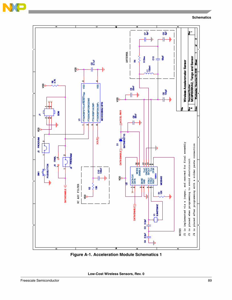
Schematics
Low-Cost Wireless Sensors, Rev. 0
Freescale Semiconductor 89
Figure A-1. Acceleration Module Schematics 1
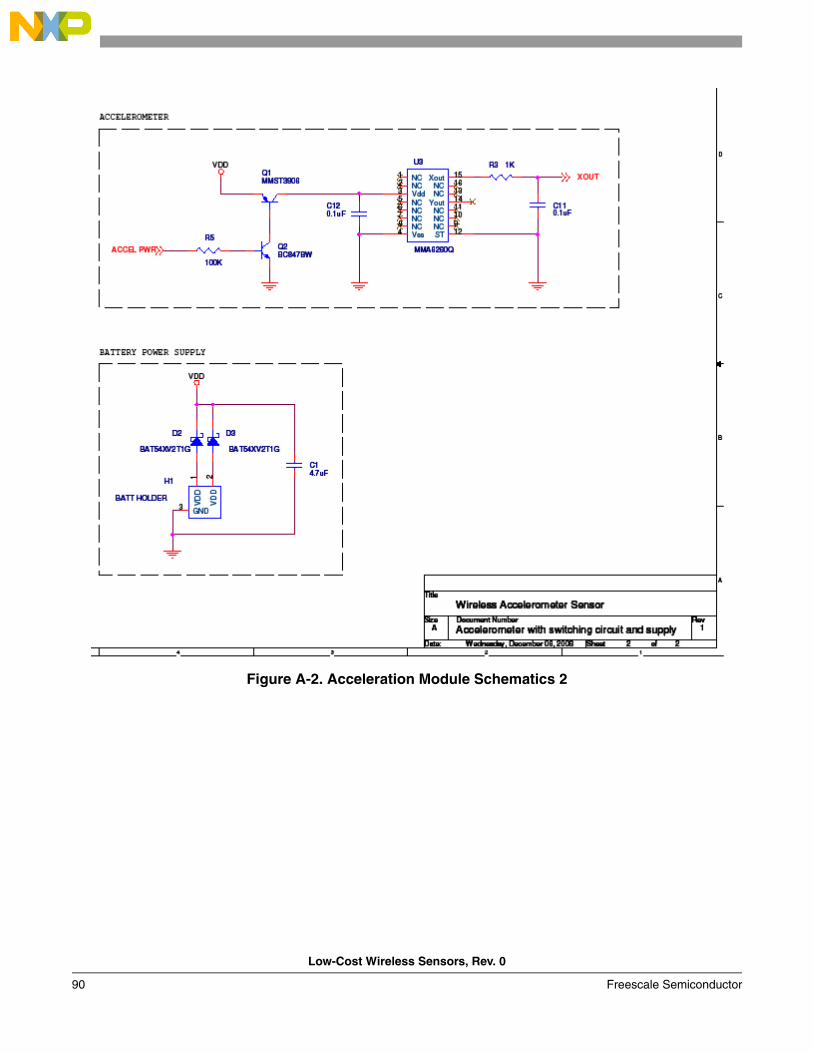
Low-Cost Wireless Sensors, Rev. 0
90 Freescale Semiconductor
Figure A-2. Acceleration Module Schematics 2
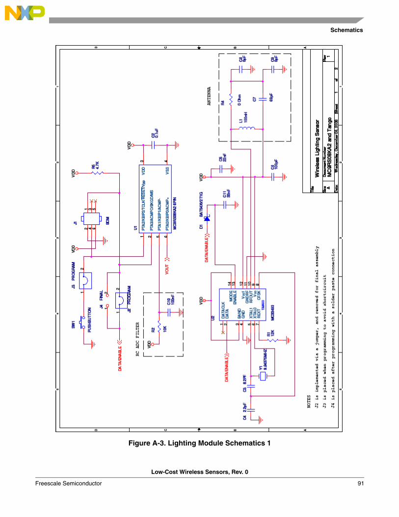
Schematics
Low-Cost Wireless Sensors, Rev. 0
Freescale Semiconductor 91
Figure A-3. Lighting Module Schematics 1
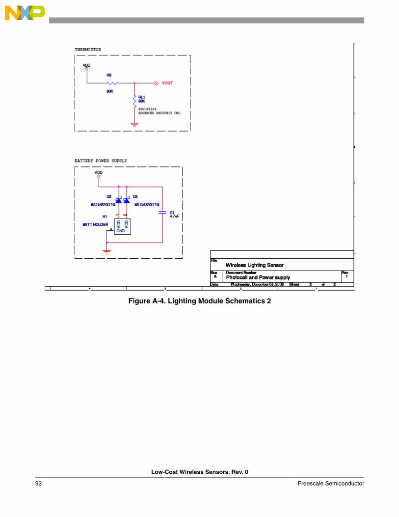
Low-Cost Wireless Sensors, Rev. 0
92 Freescale Semiconductor
Figure A-4. Lighting Module Schematics 2
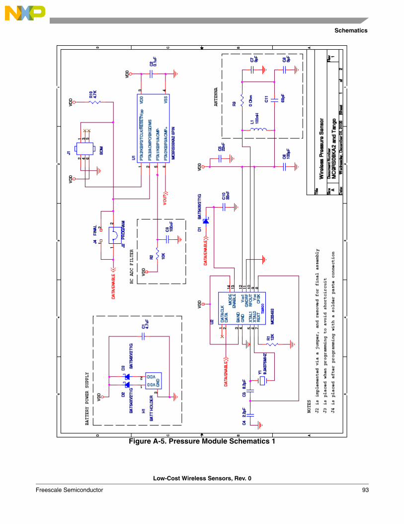
Schematics
Low-Cost Wireless Sensors, Rev. 0
Freescale Semiconductor 93
Figure A-5. Pressure Module Schematics 1
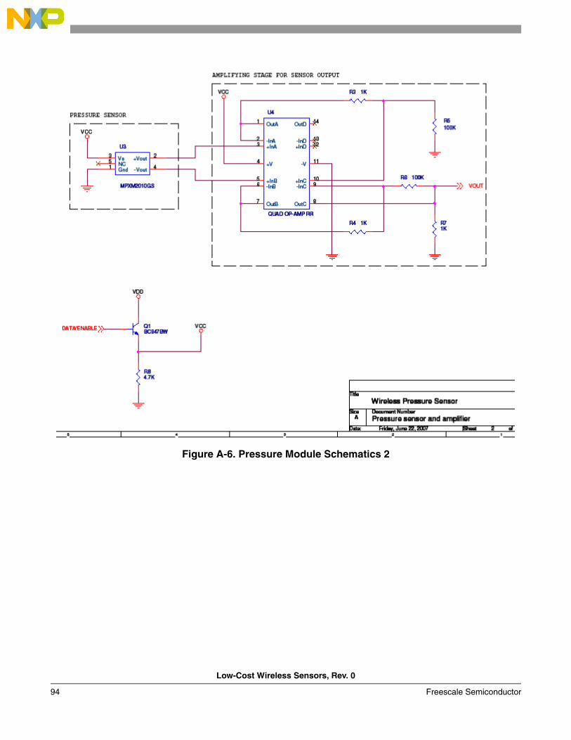
Low-Cost Wireless Sensors, Rev. 0
94 Freescale Semiconductor
Figure A-6. Pressure Module Schematics 2
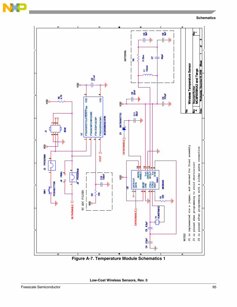
Schematics
Low-Cost Wireless Sensors, Rev. 0
Freescale Semiconductor 95
Figure A-7. Temperature Module Schematics 1
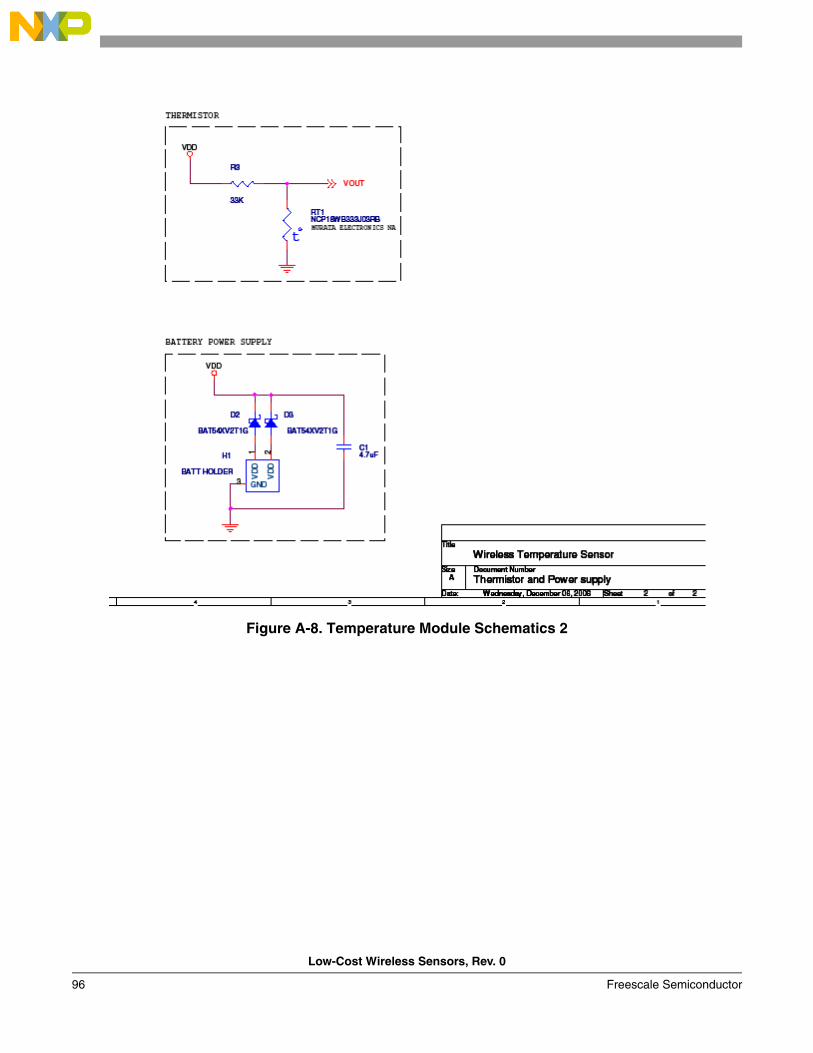
Low-Cost Wireless Sensors, Rev. 0
96 Freescale Semiconductor
Figure A-8. Temperature Module Schematics 2
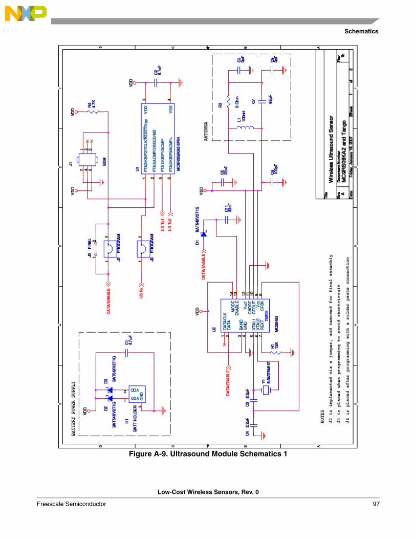
Schematics
Low-Cost Wireless Sensors, Rev. 0
Freescale Semiconductor 97
Figure A-9. Ultrasound Module Schematics 1
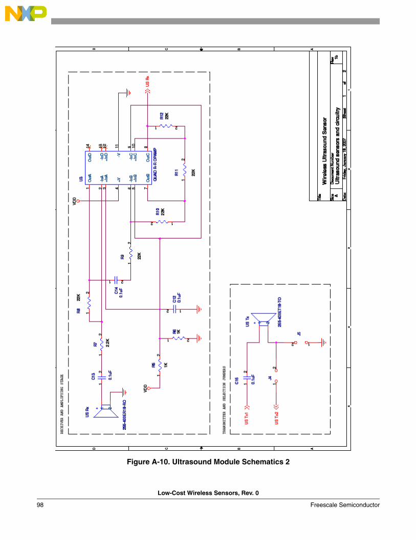
Low-Cost Wireless Sensors, Rev. 0
98 Freescale Semiconductor
Figure A-10. Ultrasound Module Schematics 2
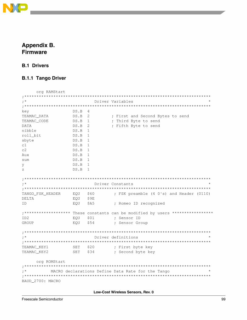
Low-Cost Wireless Sensors, Rev. 0
Freescale Semiconductor 99
Appendix B. Firmware
B.1 Drivers
B.1.1 Tango Driver
org RAMStart;*****************************************************************************;* Driver Variables *;*****************************************************************************key DS.B 4TEAMAC_DATA DS.B 2 ; First and Second Bytes to sendTEAMAC_CODE DS.B 1 ; Third Byte to sendDATA DS.B 2 ; Fifth Byte to sendnibble DS.B 1roll_bit DS.B 1sbyte DS.B 1 c1 DS.B 1c2 DS.B 1Aux DS.B 1sum DS.B 1y DS.B 1z DS.B 1
;***************************************************************************** ;* Driver Constants *;***************************************************************************** TANGO_FSK_HEADER EQU $60 ; FSK preamble (4 0's) and Header (0110)DELTA EQU $9EID EQU $A5 ; Romeo ID recognized
;******************* These constants can be modified by users *****************ID2 EQU $01 ; Sensor IDGROUP EQU $54 ; Sensor Group ;*****************************************************************************;* Driver definitions *;*****************************************************************************TEAMAC_KEY1 SET $20 ; First byte keyTEAMAC_KEY2 SET $34 ; Second byte key org ROMStart;*****************************************************************************;* MACRO declarations Define Data Rate for the Tango *;*****************************************************************************BAUD_2700: MACRO
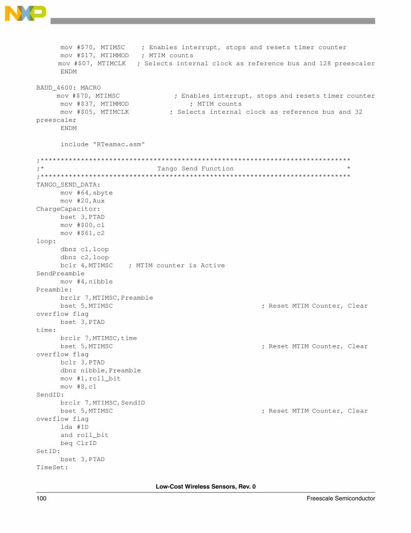
Low-Cost Wireless Sensors, Rev. 0
100 Freescale Semiconductor
mov #$70, MTIMSC ; Enables interrupt, stops and resets timer counter mov #$17, MTIMMOD ; MTIM counts mov #$07, MTIMCLK ; Selects internal clock as reference bus and 128 preescaler ENDM BAUD_4600: MACRO mov #$70, MTIMSC ; Enables interrupt, stops and resets timer counter mov #$37, MTIMMOD ; MTIM counts mov #$05, MTIMCLK ; Selects internal clock as reference bus and 32 preescaler ENDM include "RTeamac.asm" ;*****************************************************************************;* Tango Send Function *;*****************************************************************************TANGO_SEND_DATA: mov #64,sbyte mov #20,AuxChargeCapacitor: bset 3,PTAD mov #$00,c1 mov #$61,c2loop: dbnz c1,loop dbnz c2,loop bclr 4,MTIMSC ; MTIM counter is ActiveSendPreamble mov #4,nibblePreamble: brclr 7,MTIMSC,Preamble bset 5,MTIMSC ; Reset MTIM Counter, Clear overflow flag bset 3,PTAD time: brclr 7,MTIMSC,time bset 5,MTIMSC ; Reset MTIM Counter, Clear overflow flag bclr 3,PTAD dbnz nibble,Preamble mov #1,roll_bit mov #8,c1 SendID: brclr 7,MTIMSC,SendID bset 5,MTIMSC ; Reset MTIM Counter, Clear overflow flag lda #ID and roll_bit beq ClrIDSetID: bset 3,PTADTimeSet:
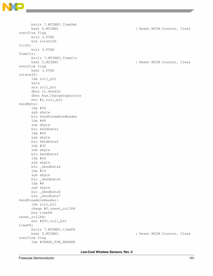
Low-Cost Wireless Sensors, Rev. 0
Freescale Semiconductor 101
brclr 7,MTIMSC,TimeSet bset 5,MTIMSC ; Reset MTIM Counter, Clear overflow flag bclr 3,PTAD bra rotateIDClrID: bclr 3,PTADTimeClr: brclr 7,MTIMSC,TimeClr bset 5,MTIMSC ; Reset MTIM Counter, Clear overflow flag bset 3,PTADrotateID: lda roll_bit asla sta roll_bit dbnz c1,SendID dbnz Aux,ChargeCapacitor mov #1,roll_bit SendByte: lda #56 sub sbyte blo SendPreambleHeader lda #48 sub sbyte blo SendData1 lda #40 sub sbyte blo SendData2 lda #32 sub sbyte blo SendData3 lda #24 sub sbyte blo _SendData4 lda #16 sub sbyte blo _SendData5 lda #8 sub sbyte blo _SendData6 bra _SendData7 SendPreambleHeader: lda roll_bit cbeqa #0,reset_rollPH bra timePHreset_rollPH: mov #$01,roll_bittimePH: brclr 7,MTIMSC,timePH bset 5,MTIMSC ; Reset MTIM Counter, Clear overflow flag lda #TANGO_FSK_HEADER
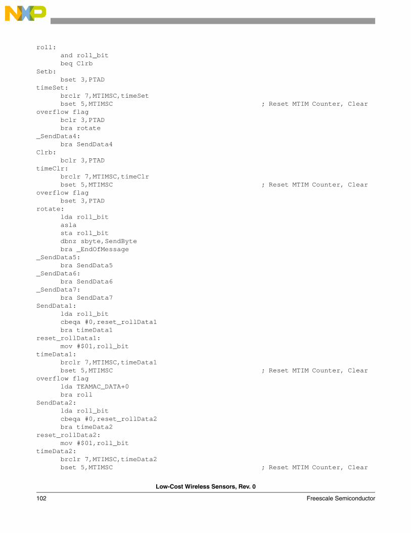
Low-Cost Wireless Sensors, Rev. 0
102 Freescale Semiconductor
roll: and roll_bit beq ClrbSetb: bset 3,PTADtimeSet: brclr 7,MTIMSC,timeSet bset 5,MTIMSC ; Reset MTIM Counter, Clear overflow flag bclr 3,PTAD bra rotate_SendData4: bra SendData4Clrb: bclr 3,PTADtimeClr: brclr 7,MTIMSC,timeClr bset 5,MTIMSC ; Reset MTIM Counter, Clear overflow flag bset 3,PTADrotate: lda roll_bit asla sta roll_bit dbnz sbyte,SendByte bra _EndOfMessage _SendData5: bra SendData5_SendData6: bra SendData6_SendData7: bra SendData7SendData1: lda roll_bit cbeqa #0,reset_rollData1 bra timeData1reset_rollData1: mov #$01,roll_bittimeData1: brclr 7,MTIMSC,timeData1 bset 5,MTIMSC ; Reset MTIM Counter, Clear overflow flag lda TEAMAC_DATA+0 bra roll SendData2: lda roll_bit cbeqa #0,reset_rollData2 bra timeData2reset_rollData2: mov #$01,roll_bittimeData2: brclr 7,MTIMSC,timeData2 bset 5,MTIMSC ; Reset MTIM Counter, Clear

Low-Cost Wireless Sensors, Rev. 0
Freescale Semiconductor 103
overflow flag lda TEAMAC_DATA+1 bra roll_EndOfMessage: bra EndOfMessageSendData3: lda roll_bit cbeqa #0,reset_rollData3 bra timeData3reset_rollData3: mov #$01,roll_bittimeData3: brclr 7,MTIMSC,timeData3 bset 5,MTIMSC ; Reset MTIM Counter, Clear overflow flag lda TEAMAC_CODE bra roll_roll: bra roll SendData4: lda roll_bit cbeqa #0,reset_rollData4 bra timeData4reset_rollData4: mov #$01,roll_bittimeData4: brclr 7,MTIMSC,timeData4 bset 5,MTIMSC ; Reset MTIM Counter, Clear overflow flag lda #GROUP bra rollSendData5: lda roll_bit cbeqa #0,reset_rollData5 bra timeData5reset_rollData5: mov #$01,roll_bittimeData5: brclr 7,MTIMSC,timeData5 bset 5,MTIMSC ; Reset MTIM Counter, Clear overflow flag lda #ID2 bra _roll SendData6: lda roll_bit cbeqa #0,reset_rollData6 bra timeData6reset_rollData6: mov #$01,roll_bittimeData6: brclr 7,MTIMSC,timeData6 bset 5,MTIMSC ; Reset MTIM Counter, Clear overflow flag
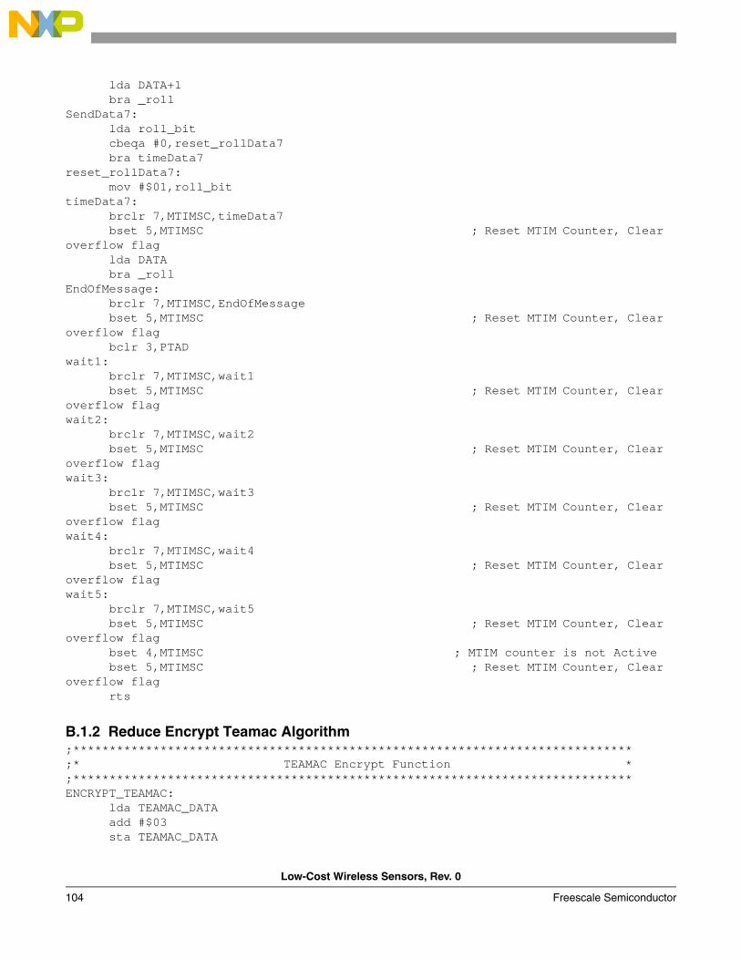
Low-Cost Wireless Sensors, Rev. 0
104 Freescale Semiconductor
lda DATA+1 bra _roll SendData7: lda roll_bit cbeqa #0,reset_rollData7 bra timeData7reset_rollData7: mov #$01,roll_bittimeData7: brclr 7,MTIMSC,timeData7 bset 5,MTIMSC ; Reset MTIM Counter, Clear overflow flag lda DATA bra _roll EndOfMessage: brclr 7,MTIMSC,EndOfMessage bset 5,MTIMSC ; Reset MTIM Counter, Clear overflow flag bclr 3,PTAD wait1: brclr 7,MTIMSC,wait1 bset 5,MTIMSC ; Reset MTIM Counter, Clear overflow flagwait2: brclr 7,MTIMSC,wait2 bset 5,MTIMSC ; Reset MTIM Counter, Clear overflow flagwait3: brclr 7,MTIMSC,wait3 bset 5,MTIMSC ; Reset MTIM Counter, Clear overflow flag wait4: brclr 7,MTIMSC,wait4 bset 5,MTIMSC ; Reset MTIM Counter, Clear overflow flagwait5: brclr 7,MTIMSC,wait5 bset 5,MTIMSC ; Reset MTIM Counter, Clear overflow flag bset 4,MTIMSC ; MTIM counter is not Active bset 5,MTIMSC ; Reset MTIM Counter, Clear overflow flag rts
B.1.2 Reduce Encrypt Teamac Algorithm;*****************************************************************************;* TEAMAC Encrypt Function *;*****************************************************************************ENCRYPT_TEAMAC: lda TEAMAC_DATA add #$03 sta TEAMAC_DATA
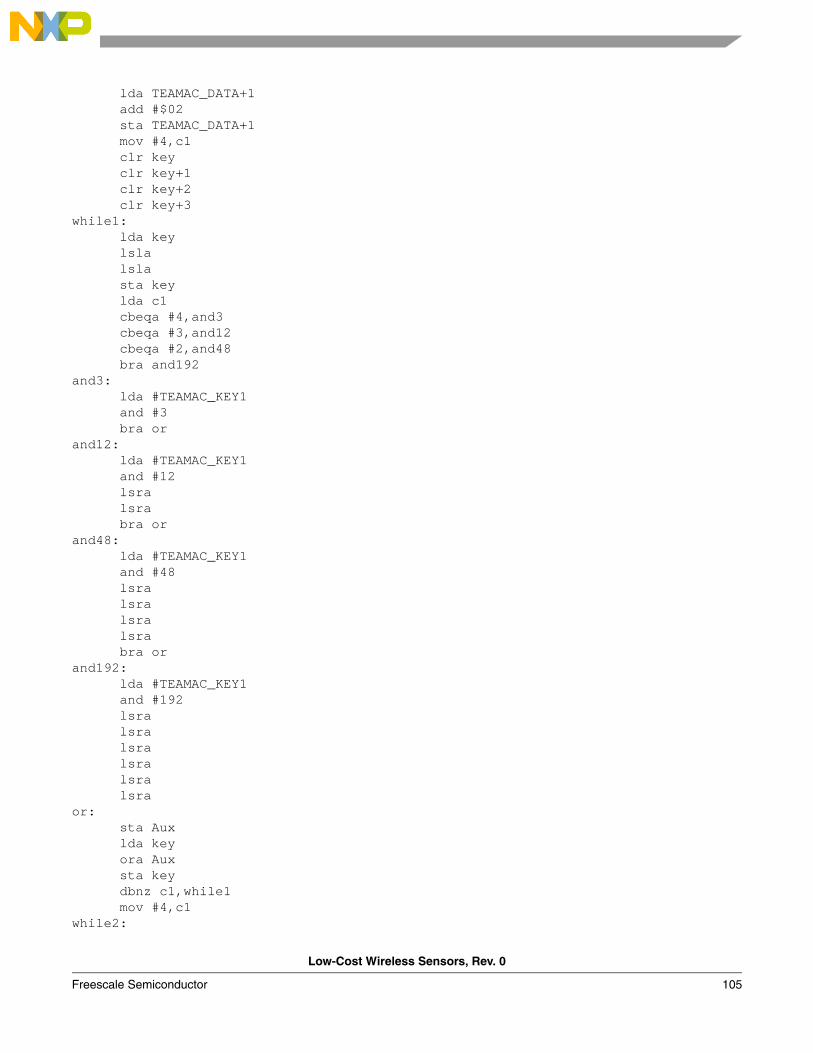
Low-Cost Wireless Sensors, Rev. 0
Freescale Semiconductor 105
lda TEAMAC_DATA+1 add #$02 sta TEAMAC_DATA+1 mov #4,c1 clr key clr key+1 clr key+2 clr key+3while1: lda key lsla lsla sta key lda c1 cbeqa #4,and3 cbeqa #3,and12 cbeqa #2,and48 bra and192and3: lda #TEAMAC_KEY1 and #3 bra orand12: lda #TEAMAC_KEY1 and #12 lsra lsra bra orand48: lda #TEAMAC_KEY1 and #48 lsra lsra lsra lsra bra orand192: lda #TEAMAC_KEY1 and #192 lsra lsra lsra lsra lsra lsra or: sta Aux lda key ora Aux sta key dbnz c1,while1 mov #4,c1while2:
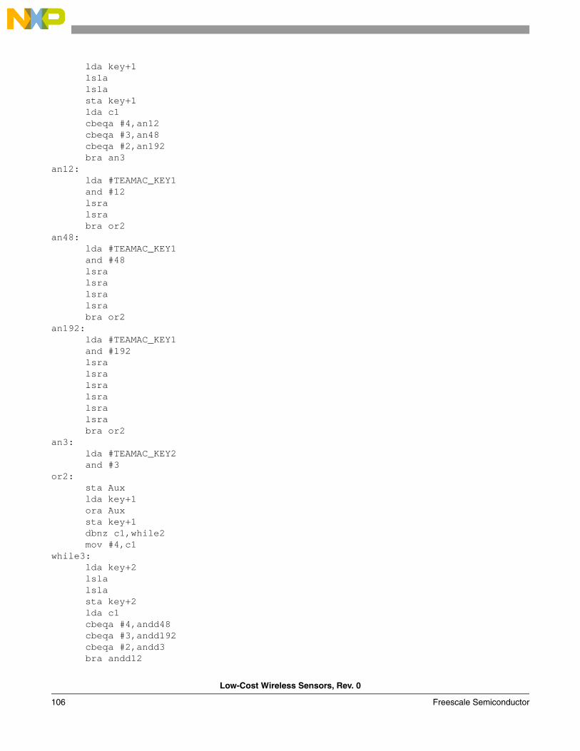
Low-Cost Wireless Sensors, Rev. 0
106 Freescale Semiconductor
lda key+1 lsla lsla sta key+1 lda c1 cbeqa #4,an12 cbeqa #3,an48 cbeqa #2,an192 bra an3an12: lda #TEAMAC_KEY1 and #12 lsra lsra bra or2an48: lda #TEAMAC_KEY1 and #48 lsra lsra lsra lsra bra or2an192: lda #TEAMAC_KEY1 and #192 lsra lsra lsra lsra lsra lsra bra or2an3: lda #TEAMAC_KEY2 and #3 or2: sta Aux lda key+1 ora Aux sta key+1 dbnz c1,while2 mov #4,c1while3: lda key+2 lsla lsla sta key+2 lda c1 cbeqa #4,andd48 cbeqa #3,andd192 cbeqa #2,andd3 bra andd12
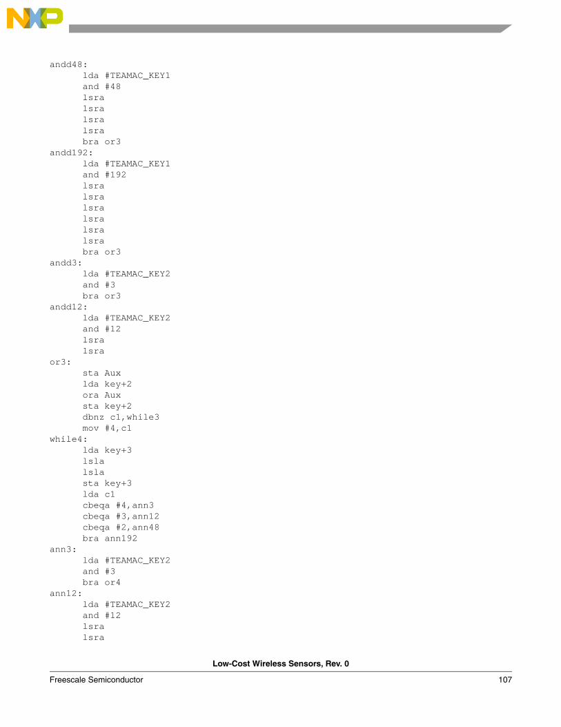
Low-Cost Wireless Sensors, Rev. 0
Freescale Semiconductor 107
andd48: lda #TEAMAC_KEY1 and #48 lsra lsra lsra lsra bra or3andd192: lda #TEAMAC_KEY1 and #192 lsra lsra lsra lsra lsra lsra bra or3andd3: lda #TEAMAC_KEY2 and #3 bra or3andd12: lda #TEAMAC_KEY2 and #12 lsra lsra or3: sta Aux lda key+2 ora Aux sta key+2 dbnz c1,while3 mov #4,c1while4: lda key+3 lsla lsla sta key+3 lda c1 cbeqa #4,ann3 cbeqa #3,ann12 cbeqa #2,ann48 bra ann192ann3: lda #TEAMAC_KEY2 and #3 bra or4ann12: lda #TEAMAC_KEY2 and #12 lsra lsra
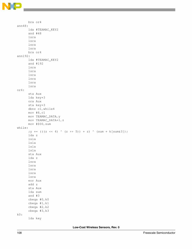
Low-Cost Wireless Sensors, Rev. 0
108 Freescale Semiconductor
bra or4ann48: lda #TEAMAC_KEY2 and #48 lsra lsra lsra lsra bra or4ann192: lda #TEAMAC_KEY2 and #192 lsra lsra lsra lsra lsra lsra or4: sta Aux lda key+3 ora Aux sta key+3 dbnz c1,while4 mov #8,c1 mov TEAMAC_DATA,y mov TEAMAC_DATA+1,z mov #$00,sumwhile: ;y += (((z << 4) ^ (z >> 5)) + z) ^ (sum + k[sum&3]); lda z lsla lsla lsla lsla sta Aux lda z lsra lsra lsra lsra lsra eor Aux add z sta Aux lda sum and #3 cbeqa #0,k0 cbeqa #1,k1 cbeqa #2,k2 cbeqa #3,k3k0: lda key
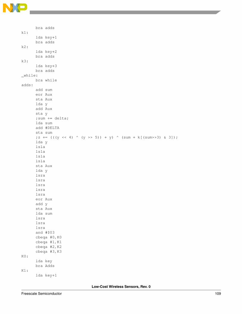
Low-Cost Wireless Sensors, Rev. 0
Freescale Semiconductor 109
bra addsk1: lda key+1 bra addsk2: lda key+2 bra addsk3: lda key+3 bra adds_while: bra whileadds: add sum eor Aux sta Aux lda y add Aux sta y ;sum += delta; lda sum add #DELTA sta sum ;z += (((y << 4) ^ (y >> 5)) + y) ^ (sum + k[(sum>>3) & 3]); lda y lsla lsla lsla lsla sta Aux lda y lsra lsra lsra lsra lsra eor Aux add y sta Aux lda sum lsra lsra lsra and #$03 cbeqa #0,K0 cbeqa #1,K1 cbeqa #2,K2 cbeqa #3,K3K0: lda key bra AddsK1: lda key+1
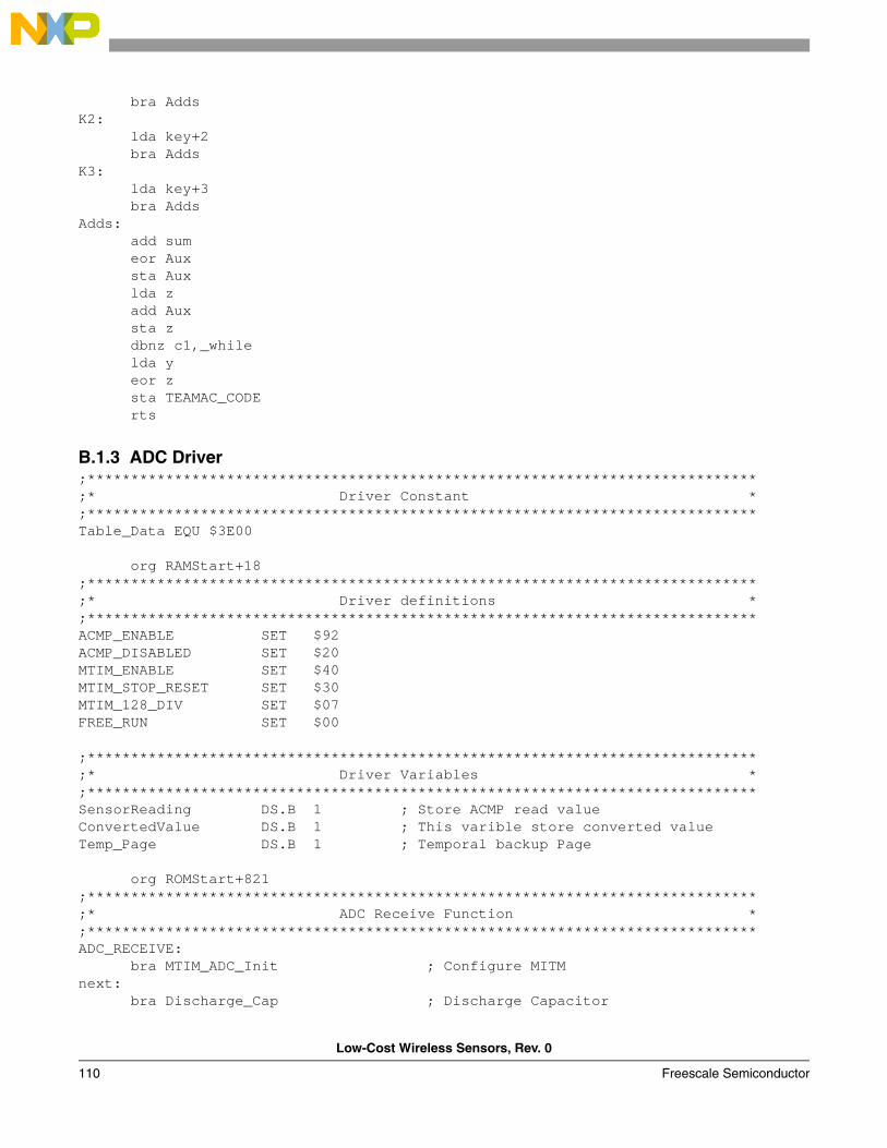
Low-Cost Wireless Sensors, Rev. 0
110 Freescale Semiconductor
bra AddsK2: lda key+2 bra AddsK3: lda key+3 bra AddsAdds: add sum eor Aux sta Aux lda z add Aux sta z dbnz c1,_while lda y eor z sta TEAMAC_CODE rts
B.1.3 ADC Driver;*****************************************************************************;* Driver Constant *;*****************************************************************************Table_Data EQU $3E00
org RAMStart+18 ;*****************************************************************************;* Driver definitions *;*****************************************************************************ACMP_ENABLE SET $92ACMP_DISABLED SET $20MTIM_ENABLE SET $40MTIM_STOP_RESET SET $30MTIM_128_DIV SET $07FREE_RUN SET $00
;*****************************************************************************;* Driver Variables *;*****************************************************************************SensorReading DS.B 1 ; Store ACMP read valueConvertedValue DS.B 1 ; This varible store converted valueTemp_Page DS.B 1 ; Temporal backup Page
org ROMStart+821;*****************************************************************************;* ADC Receive Function *;*****************************************************************************ADC_RECEIVE: bra MTIM_ADC_Init ; Configure MITMnext: bra Discharge_Cap ; Discharge Capacitor
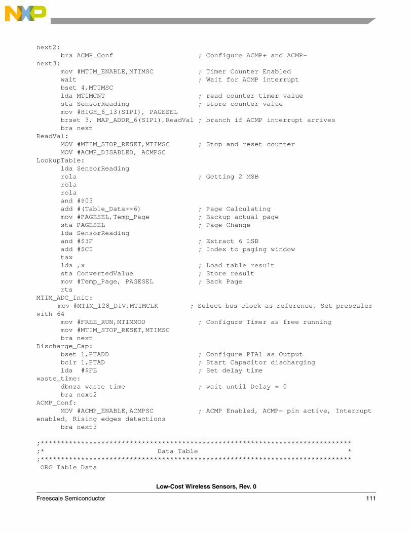
Low-Cost Wireless Sensors, Rev. 0
Freescale Semiconductor 111
next2: bra ACMP_Conf ; Configure ACMP+ and ACMP-next3: mov #MTIM_ENABLE,MTIMSC ; Timer Counter Enabled wait ; Wait for ACMP interrupt bset 4,MTIMSC lda MTIMCNT ; read counter timer value sta SensorReading ; store counter value mov #HIGH_6_13(SIP1), PAGESEL brset 3, MAP_ADDR_6(SIP1),ReadVal ; branch if ACMP interrupt arrives bra nextReadVal: MOV #MTIM_STOP_RESET,MTIMSC ; Stop and reset counter MOV #ACMP_DISABLED, ACMPSC LookupTable: lda SensorReading rola ; Getting 2 MSB rola rola and #$03 add #(Table_Data>>6) ; Page Calculating mov #PAGESEL,Temp_Page ; Backup actual page sta PAGESEL ; Page Change lda SensorReading and #$3F ; Extract 6 LSB add #$C0 ; Index to paging window tax lda ,x ; Load table result sta ConvertedValue ; Store result mov #Temp_Page, PAGESEL ; Back Page rts MTIM_ADC_Init: mov #MTIM_128_DIV,MTIMCLK ; Select bus clock as reference, Set prescaler with 64 mov #FREE_RUN,MTIMMOD ; Configure Timer as free running mov #MTIM_STOP_RESET,MTIMSC bra nextDischarge_Cap: bset 1,PTADD ; Configure PTA1 as Output bclr 1,PTAD ; Start Capacitor discharging lda #$FE ; Set delay timewaste_time: dbnza waste_time ; wait until Delay = 0 bra next2ACMP_Conf: MOV #ACMP_ENABLE,ACMPSC ; ACMP Enabled, ACMP+ pin active, Interrupt enabled, Rising edges detections bra next3 ;*****************************************************************************;* Data Table *;***************************************************************************** ORG Table_Data

Low-Cost Wireless Sensors, Rev. 0
112 Freescale Semiconductor
dc.b 0,0,0,0,0,9,13,18,22,26,30,34,38,42,46,50 dc.b 54,57,61,64,68,71,74,78,81,84,87,90,93,96,99,101 dc.b 104,107,109,112,114,117,119,121,124,126,128,130,133,135,137,139 dc.b 141,143,145,146,148,150,152,154,155,157,159,160,162,163,165,166 dc.b 168,169,170,172,173,174,176,177,178,179,181,182,183,184,185,186 dc.b 187,188,189,190,191,192,193,194,195,196,197,198,199,199,200,201 dc.b 202,203,203,204,205,205,206,207,207,208,209,209,210,211,211,212 dc.b 212,213,213,214,214,215,215,216,216,217,217,218,218,219,219,220 dc.b 220,220,221,221,222,222,222,223,223,223,224,224,224,225,225,225 dc.b 226,226,226,227,227,227,227,228,228,228,228,229,229,229,229,230 dc.b 230,230,230,230,231,231,231,231,231,232,232,232,232,232,232,233 dc.b 233,233,233,233,233,234,234,234,234,234,234,234,234,235,235,235 dc.b 235,235,235,235,235,236,236,236,236,236,236,236,236,236,236,237 dc.b 237,237,237,237,237,237,237,237,237,237,237,237,238,238,238,238 dc.b 238,238,238,238,238,238,238,238,238,238,238,238,238,239,239,239 dc.b 239,239,239,239,239,239,239,239,239,239,239,239,239,239,239,239
B.2 APPLICATIONS
B.2.1 Accelerometer;*************************************************************************;* DISCLAIMER *;* Services performed by FREESCALE in this matter are performed *;* AS IS and without any warranty. CUSTOMER retains the final decision *;* relative to the total design and functionality of the end product. *;* FREESCALE neither guarantees nor will be held liable by CUSTOMER *;* for the success of this project. FREESCALE disclaims all warranties, *;* express, implied or statutory including, but not limited to, *;* implied warranty of merchantability or fitness for a particular *;* purpose on any hardware, software ore advise supplied to the project *;* by FREESCALE, and or any product resulting from FREESCALE services. *;* In no event shall FREESCALE be liable for incidental or consequential *;* damages arising out of this agreement. CUSTOMER agrees to hold *;* FREESCALE harmless against any and all claims demands or actions *;* by anyone on account of any damage, or injury, whether commercial, *;* contractual, or tortuous, rising directly or indirectly as a result *;* of the advise or assistance supplied CUSTOMER in connection with *;* product, services or goods supplied under this Agreement. *;*************************************************************************
;*************************************************************************;* This stationery serves as the framework for a user application. *;* For a more comprehensive program that demonstrates the more *;* advanced functionality of this processor, please see the *;* demonstration applications, located in the examples *;* subdirectory of the "Freescale CodeWarrior for HC08" program *;* directory. *;*************************************************************************
; Include derivative-specific definitions INCLUDE 'derivative.inc'
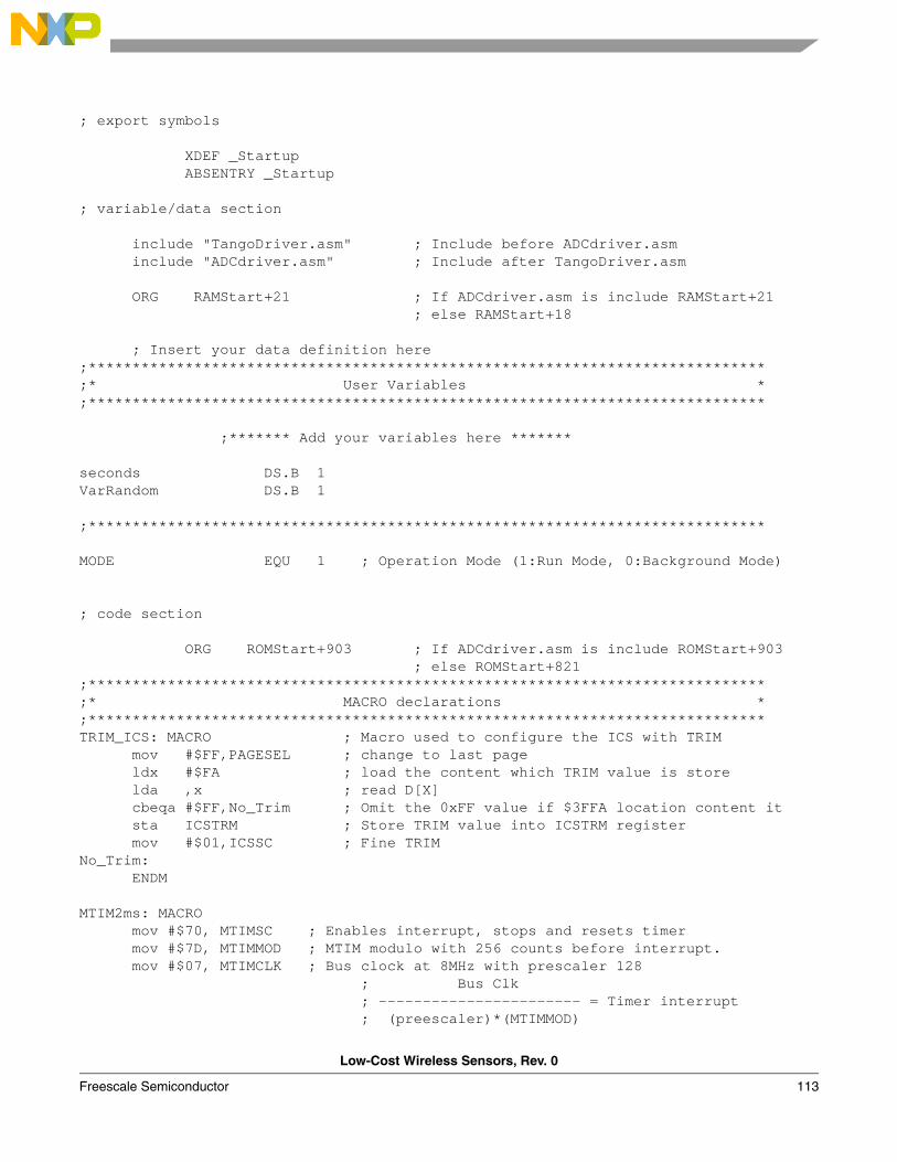
Low-Cost Wireless Sensors, Rev. 0
Freescale Semiconductor 113
; export symbols
XDEF _Startup ABSENTRY _Startup ; variable/data section
include "TangoDriver.asm" ; Include before ADCdriver.asm include "ADCdriver.asm" ; Include after TangoDriver.asm ORG RAMStart+21 ; If ADCdriver.asm is include RAMStart+21 ; else RAMStart+18 ; Insert your data definition here;*****************************************************************************;* User Variables *;***************************************************************************** ;******* Add your variables here ******* seconds DS.B 1VarRandom DS.B 1
;***************************************************************************** MODE EQU 1 ; Operation Mode (1:Run Mode, 0:Background Mode)
; code section
ORG ROMStart+903 ; If ADCdriver.asm is include ROMStart+903 ; else ROMStart+821;*****************************************************************************;* MACRO declarations *;*****************************************************************************TRIM_ICS: MACRO ; Macro used to configure the ICS with TRIM mov #$FF,PAGESEL ; change to last page ldx #$FA ; load the content which TRIM value is store lda ,x ; read D[X] cbeqa #$FF,No_Trim ; Omit the 0xFF value if $3FFA location content it sta ICSTRM ; Store TRIM value into ICSTRM register mov #$01,ICSSC ; Fine TRIM No_Trim: ENDM MTIM2ms: MACRO mov #$70, MTIMSC ; Enables interrupt, stops and resets timer mov #$7D, MTIMMOD ; MTIM modulo with 256 counts before interrupt. mov #$07, MTIMCLK ; Bus clock at 8MHz with prescaler 128 ; Bus Clk ; ----------------------- = Timer interrupt ; (preescaler)*(MTIMMOD)
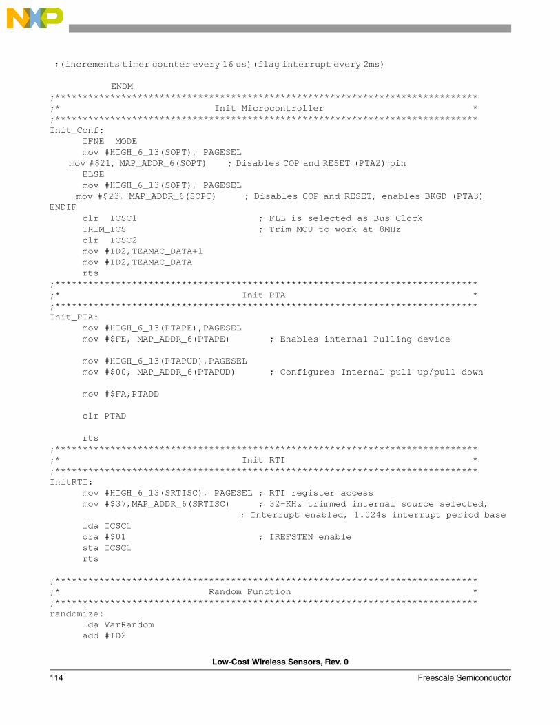
Low-Cost Wireless Sensors, Rev. 0
114 Freescale Semiconductor
;(increments timer counter every 16 us)(flag interrupt every 2ms)
ENDM ;*****************************************************************************;* Init Microcontroller *;*****************************************************************************Init_Conf: IFNE MODE mov #HIGH_6_13(SOPT), PAGESEL mov #$21, MAP_ADDR_6(SOPT) ; Disables COP and RESET (PTA2) pin ELSE mov #HIGH_6_13(SOPT), PAGESEL mov #$23, MAP_ADDR_6(SOPT) ; Disables COP and RESET, enables BKGD (PTA3) ENDIF clr ICSC1 ; FLL is selected as Bus Clock TRIM_ICS ; Trim MCU to work at 8MHz clr ICSC2 mov #ID2,TEAMAC_DATA+1 mov #ID2,TEAMAC_DATA rts;*****************************************************************************;* Init PTA *;*****************************************************************************Init_PTA: mov #HIGH_6_13(PTAPE),PAGESEL mov #$FE, MAP_ADDR_6(PTAPE) ; Enables internal Pulling device mov #HIGH_6_13(PTAPUD),PAGESEL mov #$00, MAP_ADDR_6(PTAPUD) ; Configures Internal pull up/pull down mov #$FA,PTADD clr PTAD rts;*****************************************************************************;* Init RTI *;*****************************************************************************InitRTI: mov #HIGH_6_13(SRTISC), PAGESEL ; RTI register access mov #$37,MAP_ADDR_6(SRTISC) ; 32-KHz trimmed internal source selected, ; Interrupt enabled, 1.024s interrupt period base lda ICSC1 ora #$01 ; IREFSTEN enable sta ICSC1 rts ;*****************************************************************************;* Random Function *;*****************************************************************************randomize: lda VarRandom add #ID2
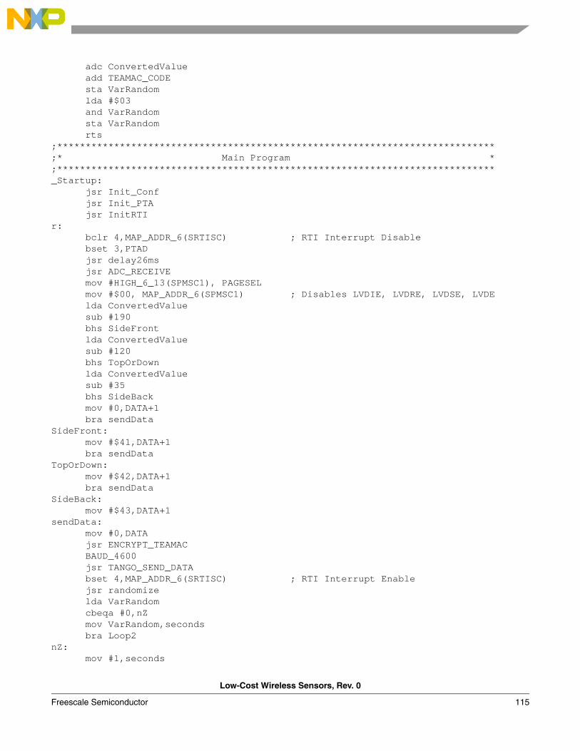
Low-Cost Wireless Sensors, Rev. 0
Freescale Semiconductor 115
adc ConvertedValue add TEAMAC_CODE sta VarRandom lda #$03 and VarRandom sta VarRandom rts;*****************************************************************************;* Main Program *;*****************************************************************************_Startup: jsr Init_Conf jsr Init_PTA jsr InitRTI r: bclr 4,MAP_ADDR_6(SRTISC) ; RTI Interrupt Disable bset 3,PTAD jsr delay26ms jsr ADC_RECEIVE mov #HIGH_6_13(SPMSC1), PAGESEL mov #$00, MAP_ADDR_6(SPMSC1) ; Disables LVDIE, LVDRE, LVDSE, LVDE lda ConvertedValue sub #190 bhs SideFront lda ConvertedValue sub #120 bhs TopOrDown lda ConvertedValue sub #35 bhs SideBack mov #0,DATA+1 bra sendData SideFront: mov #$41,DATA+1 bra sendDataTopOrDown: mov #$42,DATA+1 bra sendDataSideBack: mov #$43,DATA+1sendData: mov #0,DATA jsr ENCRYPT_TEAMAC BAUD_4600 jsr TANGO_SEND_DATA bset 4,MAP_ADDR_6(SRTISC) ; RTI Interrupt Enable jsr randomize lda VarRandom cbeqa #0,nZ mov VarRandom,seconds bra Loop2nZ: mov #1,seconds
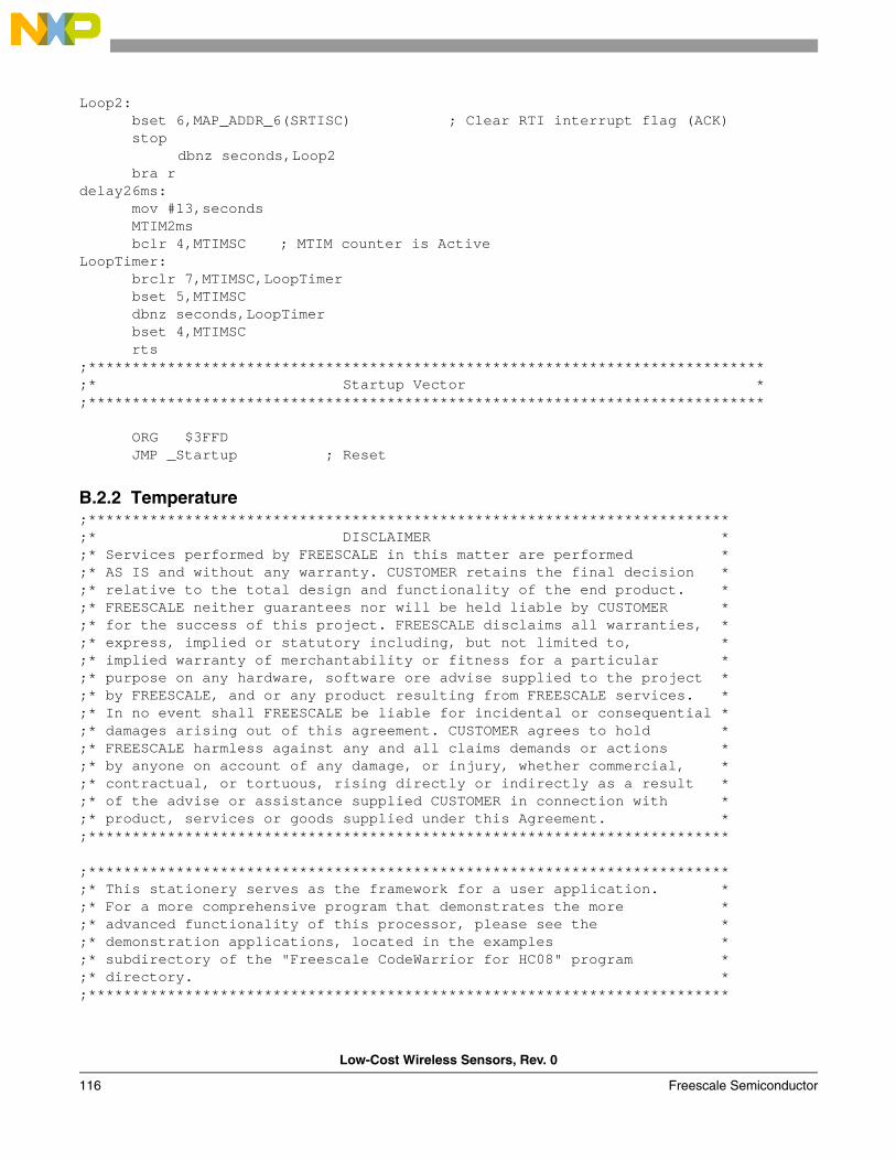
Low-Cost Wireless Sensors, Rev. 0
116 Freescale Semiconductor
Loop2: bset 6,MAP_ADDR_6(SRTISC) ; Clear RTI interrupt flag (ACK) stop
dbnz seconds,Loop2 bra rdelay26ms: mov #13,seconds MTIM2ms bclr 4,MTIMSC ; MTIM counter is ActiveLoopTimer: brclr 7,MTIMSC,LoopTimer bset 5,MTIMSC dbnz seconds,LoopTimer bset 4,MTIMSC rts;*****************************************************************************;* Startup Vector *;***************************************************************************** ORG $3FFD JMP _Startup ; Reset
B.2.2 Temperature;*************************************************************************;* DISCLAIMER *;* Services performed by FREESCALE in this matter are performed *;* AS IS and without any warranty. CUSTOMER retains the final decision *;* relative to the total design and functionality of the end product. *;* FREESCALE neither guarantees nor will be held liable by CUSTOMER *;* for the success of this project. FREESCALE disclaims all warranties, *;* express, implied or statutory including, but not limited to, *;* implied warranty of merchantability or fitness for a particular *;* purpose on any hardware, software ore advise supplied to the project *;* by FREESCALE, and or any product resulting from FREESCALE services. *;* In no event shall FREESCALE be liable for incidental or consequential *;* damages arising out of this agreement. CUSTOMER agrees to hold *;* FREESCALE harmless against any and all claims demands or actions *;* by anyone on account of any damage, or injury, whether commercial, *;* contractual, or tortuous, rising directly or indirectly as a result *;* of the advise or assistance supplied CUSTOMER in connection with *;* product, services or goods supplied under this Agreement. *;*************************************************************************
;*************************************************************************;* This stationery serves as the framework for a user application. *;* For a more comprehensive program that demonstrates the more *;* advanced functionality of this processor, please see the *;* demonstration applications, located in the examples *;* subdirectory of the "Freescale CodeWarrior for HC08" program *;* directory. *;*************************************************************************
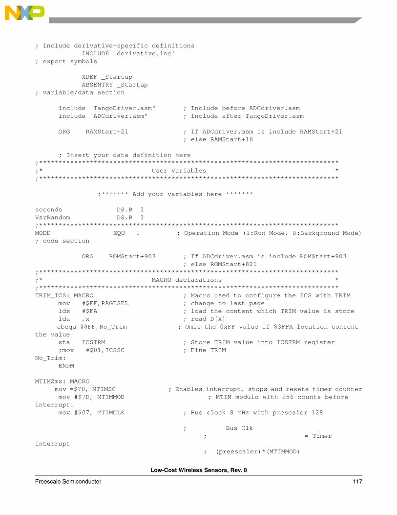
Low-Cost Wireless Sensors, Rev. 0
Freescale Semiconductor 117
; Include derivative-specific definitions INCLUDE 'derivative.inc'; export symbols
XDEF _Startup ABSENTRY _Startup; variable/data section
include "TangoDriver.asm" ; Include before ADCdriver.asm include "ADCdriver.asm" ; Include after TangoDriver.asm ORG RAMStart+21 ; If ADCdriver.asm is include RAMStart+21 ; else RAMStart+18 ; Insert your data definition here;*****************************************************************************;* User Variables *;***************************************************************************** ;******* Add your variables here ******* seconds DS.B 1VarRandom DS.B 1;*****************************************************************************MODE EQU 1 ; Operation Mode (1:Run Mode, 0:Background Mode); code section
ORG ROMStart+903 ; If ADCdriver.asm is include ROMStart+903 ; else ROMStart+821;*****************************************************************************;* MACRO declarations *;*****************************************************************************TRIM_ICS: MACRO ; Macro used to configure the ICS with TRIM mov #$FF,PAGESEL ; change to last page ldx #$FA ; load the content which TRIM value is store lda ,x ; read D[X] cbeqa #$FF,No_Trim ; Omit the 0xFF value if $3FFA location content the value sta ICSTRM ; Store TRIM value into ICSTRM register ;mov #$01,ICSSC ; Fine TRIM No_Trim: ENDM MTIM2ms: MACRO mov #$70, MTIMSC ; Enables interrupt, stops and resets timer counter mov #$7D, MTIMMOD ; MTIM modulo with 256 counts before interrupt. mov #$07, MTIMCLK ; Bus clock 8 MHz with prescaler 128 ; Bus Clk
; ----------------------- = Timer interrupt
; (preescaler)*(MTIMMOD)
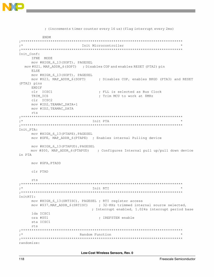
Low-Cost Wireless Sensors, Rev. 0
118 Freescale Semiconductor
; (increments timer counter every 16 us)(flag interrupt every 2ms)
ENDM ;*****************************************************************************;* Init Microcontroller *;*****************************************************************************Init_Conf: IFNE MODE mov #HIGH_6_13(SOPT), PAGESEL mov #$21, MAP_ADDR_6(SOPT) ; Disables COP and enables RESET (PTA2) pin ELSE mov #HIGH_6_13(SOPT), PAGESEL mov #$23, MAP_ADDR_6(SOPT) ; Disables COP, enables BKGD (PTA3) and RESET (PTA2) pins ENDIF clr ICSC1 ; FLL is selected as Bus Clock TRIM_ICS ; Trim MCU to work at 8MHz clr ICSC2 mov #ID2,TEAMAC_DATA+1 mov #ID2,TEAMAC_DATA rts;*****************************************************************************;* Init PTA *;*****************************************************************************Init_PTA: mov #HIGH_6_13(PTAPE),PAGESEL mov #$FE, MAP_ADDR_6(PTAPE) ; Enables internal Pulling device mov #HIGH_6_13(PTAPUD),PAGESEL mov #$00, MAP_ADDR_6(PTAPUD) ; Configures Internal pull up/pull down device in PTA mov #$FA,PTADD clr PTAD rts;*****************************************************************************;* Init RTI *;*****************************************************************************InitRTI: mov #HIGH_6_13(SRTISC), PAGESEL ; RTI register access mov #$37,MAP_ADDR_6(SRTISC) ; 32-KHz trimmed internal source selected, ; Interrupt enabled, 1.024s interrupt period base lda ICSC1 ora #$01 ; IREFSTEN enable sta ICSC1 rts ;*****************************************************************************;* Random Function *;*****************************************************************************randomize:
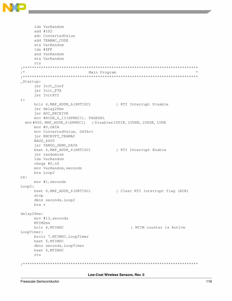
Low-Cost Wireless Sensors, Rev. 0
Freescale Semiconductor 119
lda VarRandom add #ID2 adc ConvertedValue add TEAMAC_CODE sta VarRandom lda #$FF and VarRandom sta VarRandom rts;*****************************************************************************;* Main Program *;*****************************************************************************_Startup: jsr Init_Conf jsr Init_PTA jsr InitRTI r: bclr 4,MAP_ADDR_6(SRTISC) ; RTI Interrupt Disable jsr delay26ms jsr ADC_RECEIVE mov #HIGH_6_13(SPMSC1), PAGESEL mov #$00, MAP_ADDR_6(SPMSC1) ; Disables LVDIE, LVDRE, LVDSE, LVDE mov #0,DATA mov ConvertedValue, DATA+1 jsr ENCRYPT_TEAMAC BAUD_4600 jsr TANGO_SEND_DATA bset 4,MAP_ADDR_6(SRTISC) ; RTI Interrupt Enable jsr randomize lda VarRandom cbeqa #0,nZ mov VarRandom,seconds bra Loop2nZ: mov #1,seconds Loop2: bset 6,MAP_ADDR_6(SRTISC) ; Clear RTI interrupt flag (ACK) stop dbnz seconds,Loop2 bra r delay26ms: mov #13,seconds MTIM2ms bclr 4,MTIMSC ; MTIM counter is ActiveLoopTimer: brclr 7,MTIMSC,LoopTimer bset 5,MTIMSC dbnz seconds,LoopTimer bset 4,MTIMSC rts ;*****************************************************************************
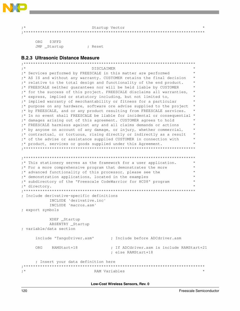
Low-Cost Wireless Sensors, Rev. 0
120 Freescale Semiconductor
;* Startup Vector *;***************************************************************************** ORG $3FFD JMP _Startup ; Reset
B.2.3 Ultrasonic Distance Measure;*************************************************************************;* DISCLAIMER *;* Services performed by FREESCALE in this matter are performed *;* AS IS and without any warranty. CUSTOMER retains the final decision *;* relative to the total design and functionality of the end product. *;* FREESCALE neither guarantees nor will be held liable by CUSTOMER *;* for the success of this project. FREESCALE disclaims all warranties, *;* express, implied or statutory including, but not limited to, *;* implied warranty of merchantability or fitness for a particular *;* purpose on any hardware, software ore advise supplied to the project *;* by FREESCALE, and or any product resulting from FREESCALE services. *;* In no event shall FREESCALE be liable for incidental or consequential *;* damages arising out of this agreement. CUSTOMER agrees to hold *;* FREESCALE harmless against any and all claims demands or actions *;* by anyone on account of any damage, or injury, whether commercial, *;* contractual, or tortuous, rising directly or indirectly as a result *;* of the advise or assistance supplied CUSTOMER in connection with *;* product, services or goods supplied under this Agreement. *;*************************************************************************
;*************************************************************************;* This stationery serves as the framework for a user application. *;* For a more comprehensive program that demonstrates the more *;* advanced functionality of this processor, please see the *;* demonstration applications, located in the examples *;* subdirectory of the "Freescale CodeWarrior for HC08" program *;* directory. *;*************************************************************************; Include derivative-specific definitions INCLUDE 'derivative.inc' INCLUDE 'macros.asm'; export symbols XDEF _Startup ABSENTRY _Startup; variable/data section
include "TangoDriver.asm" ; Include before ADCdriver.asm ORG RAMStart+18 ; If ADCdriver.asm is include RAMStart+21 ; else RAMStart+18
; Insert your data definition here;*****************************************************************************;* RAM Variables *
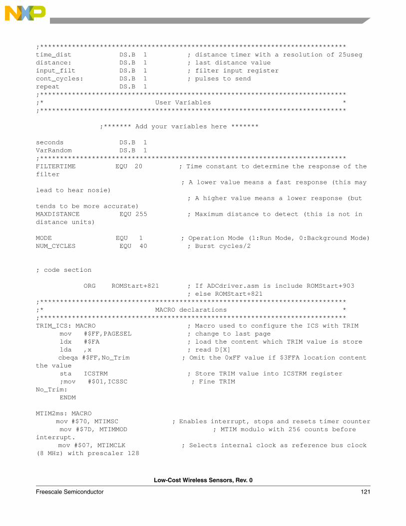
Low-Cost Wireless Sensors, Rev. 0
Freescale Semiconductor 121
;*****************************************************************************time_dist DS.B 1 ; distance timer with a resolution of 25usegdistance: DS.B 1 ; last distance valueinput_filt DS.B 1 ; filter input register cont_cycles: DS.B 1 ; pulses to sendrepeat DS.B 1;*****************************************************************************;* User Variables *;***************************************************************************** ;******* Add your variables here ******* seconds DS.B 1VarRandom DS.B 1;*****************************************************************************FILTERTIME EQU 20 ; Time constant to determine the response of the filter ; A lower value means a fast response (this may lead to hear nosie) ; A higher value means a lower response (but tends to be more accurate)MAXDISTANCE EQU 255 ; Maximum distance to detect (this is not in distance units)
MODE EQU 1 ; Operation Mode (1:Run Mode, 0:Background Mode)NUM_CYCLES EQU 40 ; Burst cycles/2
; code section
ORG ROMStart+821 ; If ADCdriver.asm is include ROMStart+903 ; else ROMStart+821;*****************************************************************************;* MACRO declarations *;*****************************************************************************TRIM_ICS: MACRO ; Macro used to configure the ICS with TRIM mov #$FF,PAGESEL ; change to last page ldx #$FA ; load the content which TRIM value is store lda ,x ; read D[X] cbeqa #$FF,No_Trim ; Omit the 0xFF value if $3FFA location content the value sta ICSTRM ; Store TRIM value into ICSTRM register ;mov #$01,ICSSC ; Fine TRIM No_Trim: ENDM MTIM2ms: MACRO mov #$70, MTIMSC ; Enables interrupt, stops and resets timer counter mov #$7D, MTIMMOD ; MTIM modulo with 256 counts before interrupt. mov #$07, MTIMCLK ; Selects internal clock as reference bus clock (8 MHz) with prescaler 128
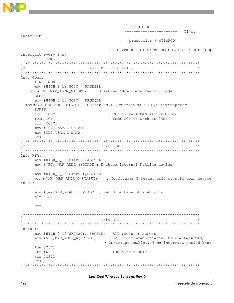
Low-Cost Wireless Sensors, Rev. 0
122 Freescale Semiconductor
; Bus Clk ; ----------------------- = Timer
interrupt ; (preescaler)*(MTIMMOD)
; (increments timer counter every 16 us)(flag interrupt every 2ms)
ENDM ;*****************************************************************************;* Init Microcontroller *;*****************************************************************************Init_Conf: IFNE MODE mov #HIGH_6_13(SOPT), PAGESEL mov #$20, MAP_ADDR_6(SOPT) ; Disables COP and enables Stop mode ELSE mov #HIGH_6_13(SOPT), PAGESEL mov #$23, MAP_ADDR_6(SOPT) ; Disables COP, enables BKGD (PTA3) and Stop mode ENDIF clr ICSC1 ; FLL is selected as Bus Clock TRIM_ICS ; Trim MCU to work at 8MHz clr ICSC2 mov #ID2,TEAMAC_DATA+1 mov #ID2,TEAMAC_DATA rts;*****************************************************************************;* Init PTA *;*****************************************************************************Init_PTA: mov #HIGH_6_13(PTAPE),PAGESEL mov #$FF, MAP_ADDR_6(PTAPE); Enables internal Pulling device mov #HIGH_6_13(PTAPUD),PAGESEL mov #$00, MAP_ADDR_6(PTAPUD) ; Configures Internal pull up/pull down device in PTA mov #(mPTADD_PTADD1),PTADD ; Set direction of PTAD pins clr PTAD rts ;*****************************************************************************;* Init RTI *;*****************************************************************************InitRTI: mov #HIGH_6_13(SRTISC), PAGESEL ; RTI register access mov #$31,MAP_ADDR_6(SRTISC) ; 32-KHz trimmed internal source selected, ; Interrupt enabled, 8 ms interrupt period base lda ICSC1 ora #$01 ; IREFSTEN enable sta ICSC1 rts ;*****************************************************************************
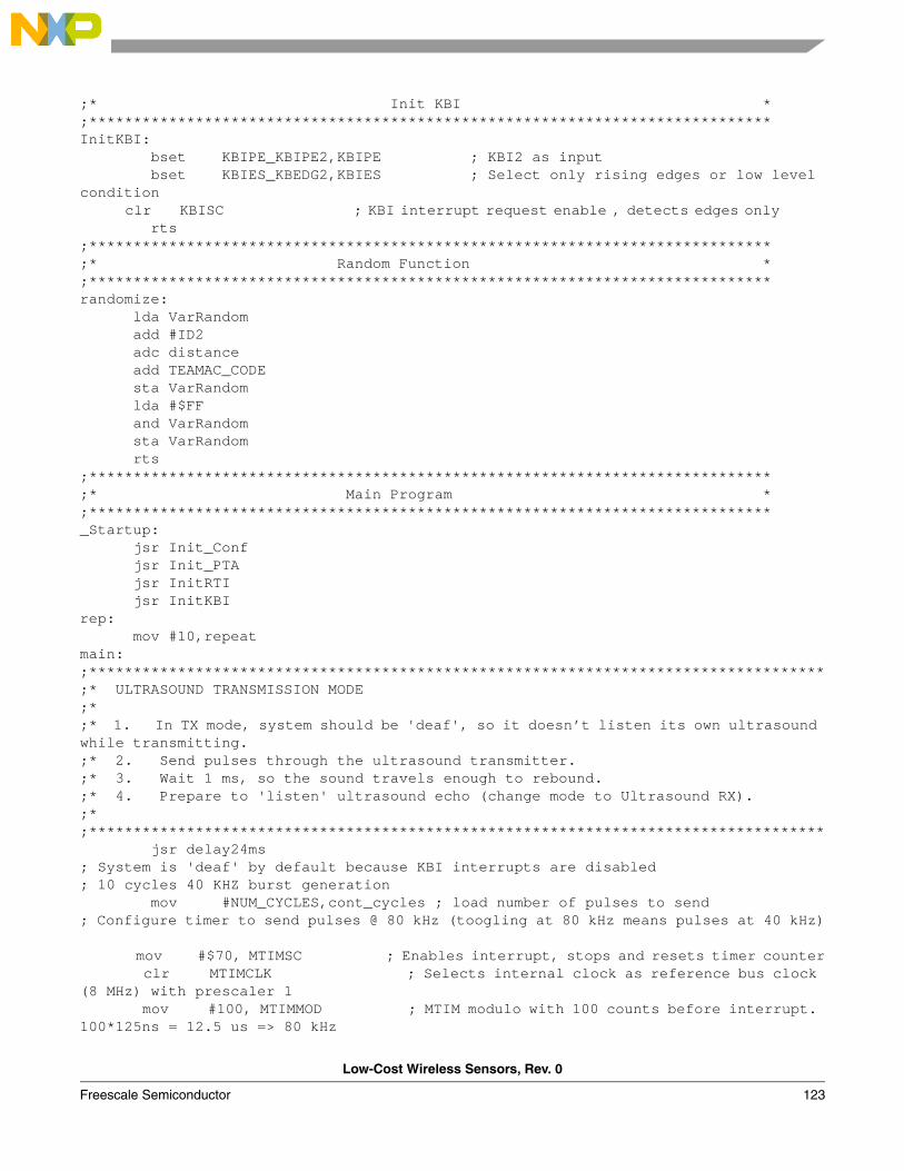
Low-Cost Wireless Sensors, Rev. 0
Freescale Semiconductor 123
;* Init KBI *;*****************************************************************************InitKBI: bset KBIPE_KBIPE2,KBIPE ; KBI2 as input bset KBIES_KBEDG2,KBIES ; Select only rising edges or low level condition clr KBISC ; KBI interrupt request enable , detects edges only rts;*****************************************************************************;* Random Function *;*****************************************************************************randomize: lda VarRandom add #ID2 adc distance add TEAMAC_CODE sta VarRandom lda #$FF and VarRandom sta VarRandom rts;*****************************************************************************;* Main Program *;*****************************************************************************_Startup: jsr Init_Conf jsr Init_PTA jsr InitRTI jsr InitKBIrep: mov #10,repeat main:;***********************************************************************************;* ULTRASOUND TRANSMISSION MODE;*;* 1. In TX mode, system should be 'deaf', so it doesn’t listen its own ultrasound while transmitting.;* 2. Send pulses through the ultrasound transmitter.;* 3. Wait 1 ms, so the sound travels enough to rebound.;* 4. Prepare to 'listen' ultrasound echo (change mode to Ultrasound RX).;*;*********************************************************************************** jsr delay24ms; System is 'deaf' by default because KBI interrupts are disabled; 10 cycles 40 KHZ burst generation mov #NUM_CYCLES,cont_cycles ; load number of pulses to send; Configure timer to send pulses @ 80 kHz (toogling at 80 kHz means pulses at 40 kHz)
mov #$70, MTIMSC ; Enables interrupt, stops and resets timer counter clr MTIMCLK ; Selects internal clock as reference bus clock (8 MHz) with prescaler 1 mov #100, MTIMMOD ; MTIM modulo with 100 counts before interrupt. 100*125ns = 12.5 us => 80 kHz
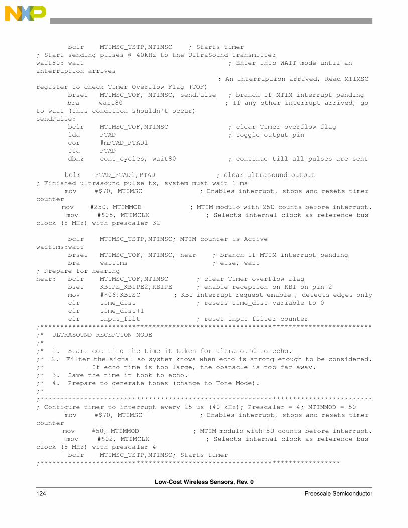
Low-Cost Wireless Sensors, Rev. 0
124 Freescale Semiconductor
bclr MTIMSC_TSTP,MTIMSC ; Starts timer ; Start sending pulses @ 40kHz to the UltraSound transmitterwait80: wait ; Enter into WAIT mode until an interruption arrives ; An interruption arrived, Read MTIMSC register to check Timer Overflow Flag (TOF) brset MTIMSC_TOF, MTIMSC, sendPulse ; branch if MTIM interrupt pending bra wait80 ; If any other interrupt arrived, go to wait (this condition shouldn't occur)sendPulse: bclr MTIMSC_TOF,MTIMSC ; clear Timer overflow flag lda PTAD ; toggle output pin eor #mPTAD_PTAD1 sta PTAD dbnz cont_cycles, wait80 ; continue till all pulses are sent bclr PTAD_PTAD1,PTAD ; clear ultrasound output ; Finished ultrasound pulse tx, system must wait 1 ms mov #$70, MTIMSC ; Enables interrupt, stops and resets timer counter mov #250, MTIMMOD ; MTIM modulo with 250 counts before interrupt. mov #$05, MTIMCLK ; Selects internal clock as reference bus clock (8 MHz) with prescaler 32 bclr MTIMSC_TSTP,MTIMSC; MTIM counter is Activewait1ms:wait brset MTIMSC_TOF, MTIMSC, hear ; branch if MTIM interrupt pending bra wait1ms ; else, wait; Prepare for hearinghear: bclr MTIMSC_TOF,MTIMSC ; clear Timer overflow flag bset KBIPE_KBIPE2,KBIPE ; enable reception on KBI on pin 2 mov #$06,KBISC ; KBI interrupt request enable , detects edges only clr time_dist ; resets time_dist variable to 0 clr time_dist+1 clr input_filt ; reset input filter counter;***********************************************************************************;* ULTRASOUND RECEPTION MODE;*;* 1. Start counting the time it takes for ultrasound to echo.;* 2. Filter the signal so system knows when echo is strong enough to be considered.;* - If echo time is too large, the obstacle is too far away.;* 3. Save the time it took to echo.;* 4. Prepare to generate tones (change to Tone Mode).;*;***********************************************************************************; Configure timer to interrupt every 25 us (40 kHz); Prescaler = 4; MTIMMOD = 50 mov #$70, MTIMSC ; Enables interrupt, stops and resets timer counter mov #50, MTIMMOD ; MTIM modulo with 50 counts before interrupt. mov #$02, MTIMCLK ; Selects internal clock as reference bus clock (8 MHz) with prescaler 4 bclr MTIMSC_TSTP,MTIMSC; Starts timer;***************************************************************************
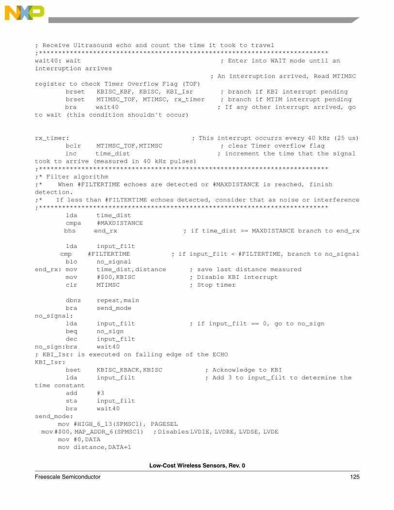
Low-Cost Wireless Sensors, Rev. 0
Freescale Semiconductor 125
; Receive Ultrasound echo and count the time it took to travel;***************************************************************************wait40: wait ; Enter into WAIT mode until an interruption arrives ; An interruption arrived, Read MTIMSC register to check Timer Overflow Flag (TOF) brset KBISC_KBF, KBISC, KBI_Isr ; branch if KBI interrupt pending brset MTIMSC_TOF, MTIMSC, rx_timer ; branch if MTIM interrupt pending bra wait40 ; If any other interrupt arrived, go to wait (this condition shouldn't occur)
rx_timer: ; This interrupt occurrs every 40 kHz (25 us) bclr MTIMSC_TOF,MTIMSC ; clear Timer overflow flag inc time_dist ; increment the time that the signal took to arrive (measured in 40 kHz pulses) ;***************************************************************************;* Filter algorithm;* When #FILTERTIME echoes are detected or #MAXDISTANCE is reached, finish detection.;* If less than #FILTERTIME echoes detected, consider that as noise or interference;*************************************************************************** lda time_dist cmpa #MAXDISTANCE bhs end_rx ; if time_dist >= MAXDISTANCE branch to end_rx
lda input_filt cmp #FILTERTIME ; if input_filt < #FILTERTIME, branch to no_signal blo no_signalend_rx: mov time_dist,distance ; save last distance measured mov #$00,KBISC ; Disable KBI interrupt clr MTIMSC ; Stop timer
dbnz repeat,main bra send_mode no_signal: lda input_filt ; if input_filt == 0, go to no_sign beq no_sign dec input_filtno_sign:bra wait40; KBI_Isr: is executed on falling edge of the ECHOKBI_Isr: bset KBISC_KBACK,KBISC ; Acknowledge to KBI lda input_filt ; Add 3 to input_filt to determine the time constant add #3 sta input_filt bra wait40 send_mode: mov #HIGH_6_13(SPMSC1), PAGESEL mov #$00, MAP_ADDR_6(SPMSC1) ; Disables LVDIE, LVDRE, LVDSE, LVDE mov #0,DATA mov distance,DATA+1
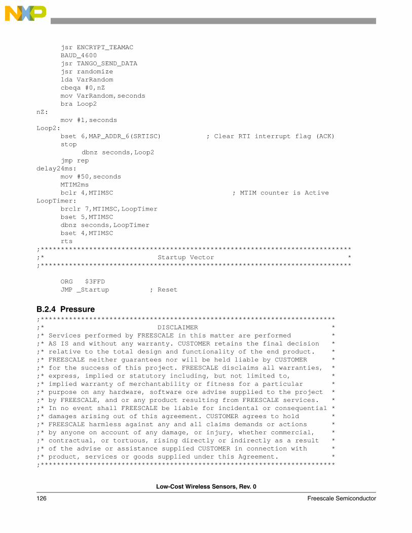
Low-Cost Wireless Sensors, Rev. 0
126 Freescale Semiconductor
jsr ENCRYPT_TEAMAC BAUD_4600 jsr TANGO_SEND_DATA jsr randomize lda VarRandom cbeqa #0,nZ mov VarRandom,seconds bra Loop2nZ: mov #1,seconds Loop2: bset 6,MAP_ADDR_6(SRTISC) ; Clear RTI interrupt flag (ACK) stop
dbnz seconds,Loop2 jmp repdelay24ms: mov #50,seconds MTIM2ms bclr 4,MTIMSC ; MTIM counter is ActiveLoopTimer: brclr 7,MTIMSC,LoopTimer bset 5,MTIMSC dbnz seconds,LoopTimer bset 4,MTIMSC rts ;*****************************************************************************;* Startup Vector *;***************************************************************************** ORG $3FFD JMP _Startup ; Reset
B.2.4 Pressure;*************************************************************************;* DISCLAIMER *;* Services performed by FREESCALE in this matter are performed *;* AS IS and without any warranty. CUSTOMER retains the final decision *;* relative to the total design and functionality of the end product. *;* FREESCALE neither guarantees nor will be held liable by CUSTOMER *;* for the success of this project. FREESCALE disclaims all warranties, *;* express, implied or statutory including, but not limited to, *;* implied warranty of merchantability or fitness for a particular *;* purpose on any hardware, software ore advise supplied to the project *;* by FREESCALE, and or any product resulting from FREESCALE services. *;* In no event shall FREESCALE be liable for incidental or consequential *;* damages arising out of this agreement. CUSTOMER agrees to hold *;* FREESCALE harmless against any and all claims demands or actions *;* by anyone on account of any damage, or injury, whether commercial, *;* contractual, or tortuous, rising directly or indirectly as a result *;* of the advise or assistance supplied CUSTOMER in connection with *;* product, services or goods supplied under this Agreement. *;*************************************************************************
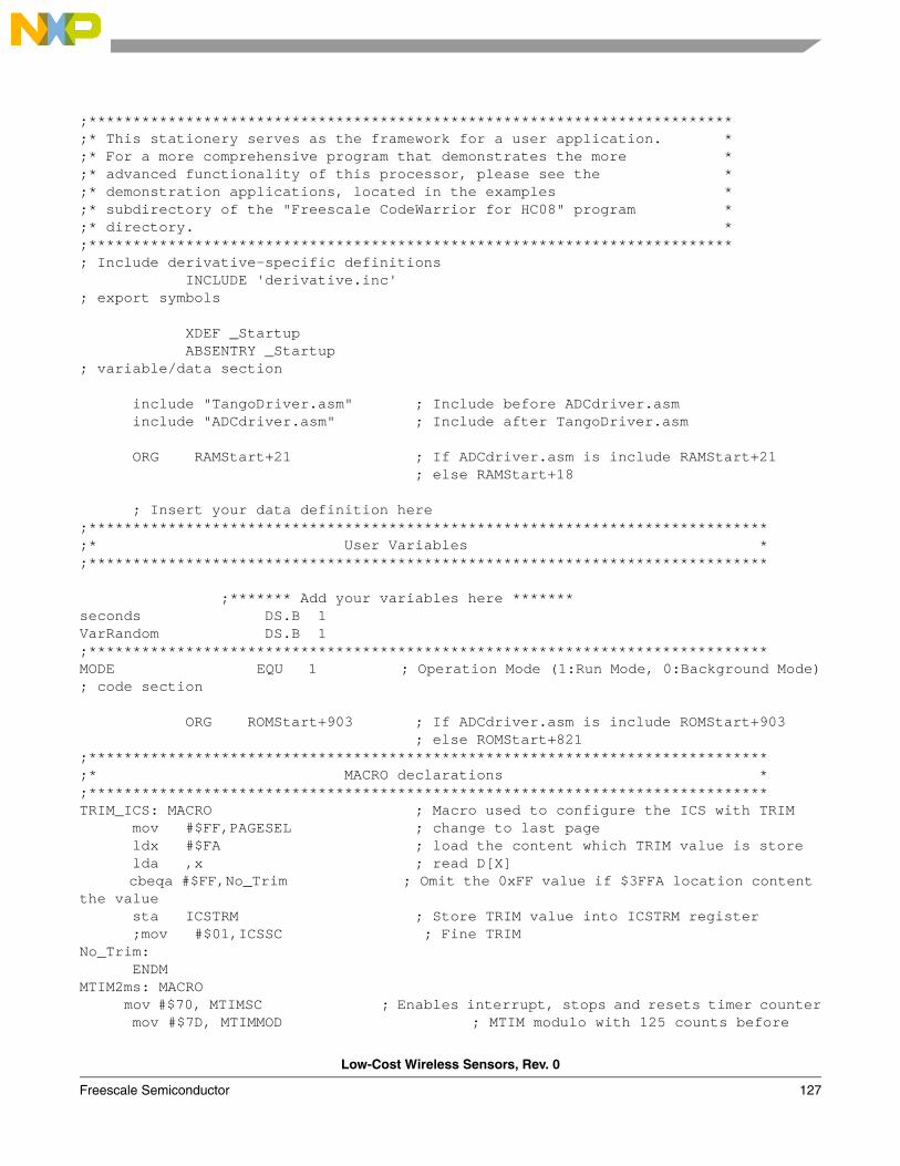
Low-Cost Wireless Sensors, Rev. 0
Freescale Semiconductor 127
;*************************************************************************;* This stationery serves as the framework for a user application. *;* For a more comprehensive program that demonstrates the more *;* advanced functionality of this processor, please see the *;* demonstration applications, located in the examples *;* subdirectory of the "Freescale CodeWarrior for HC08" program *;* directory. *;*************************************************************************; Include derivative-specific definitions INCLUDE 'derivative.inc'; export symbols
XDEF _Startup ABSENTRY _Startup; variable/data section
include "TangoDriver.asm" ; Include before ADCdriver.asm include "ADCdriver.asm" ; Include after TangoDriver.asm ORG RAMStart+21 ; If ADCdriver.asm is include RAMStart+21 ; else RAMStart+18
; Insert your data definition here;*****************************************************************************;* User Variables *;***************************************************************************** ;******* Add your variables here *******seconds DS.B 1VarRandom DS.B 1;*****************************************************************************MODE EQU 1 ; Operation Mode (1:Run Mode, 0:Background Mode); code section
ORG ROMStart+903 ; If ADCdriver.asm is include ROMStart+903 ; else ROMStart+821;*****************************************************************************;* MACRO declarations *;*****************************************************************************TRIM_ICS: MACRO ; Macro used to configure the ICS with TRIM mov #$FF,PAGESEL ; change to last page ldx #$FA ; load the content which TRIM value is store lda ,x ; read D[X] cbeqa #$FF,No_Trim ; Omit the 0xFF value if $3FFA location content the value sta ICSTRM ; Store TRIM value into ICSTRM register ;mov #$01,ICSSC ; Fine TRIM No_Trim: ENDMMTIM2ms: MACRO mov #$70, MTIMSC ; Enables interrupt, stops and resets timer counter mov #$7D, MTIMMOD ; MTIM modulo with 125 counts before
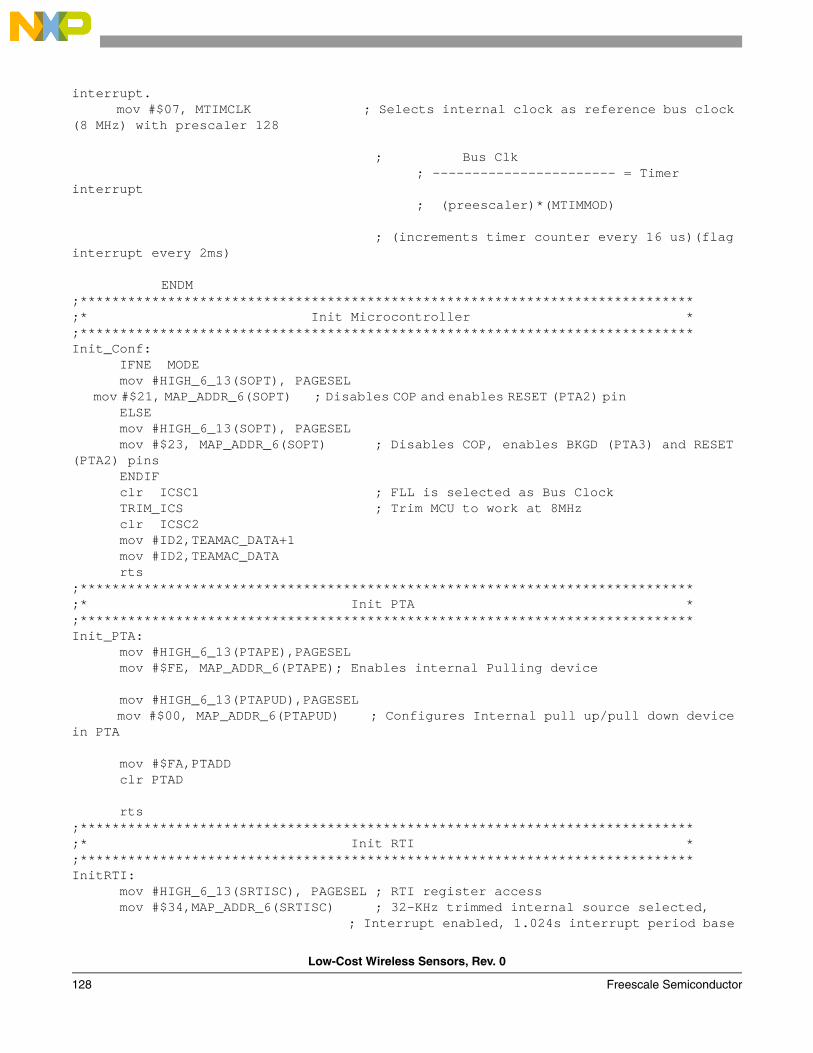
Low-Cost Wireless Sensors, Rev. 0
128 Freescale Semiconductor
interrupt. mov #$07, MTIMCLK ; Selects internal clock as reference bus clock (8 MHz) with prescaler 128 ; Bus Clk
; ----------------------- = Timer interrupt
; (preescaler)*(MTIMMOD)
; (increments timer counter every 16 us)(flag interrupt every 2ms)
ENDM ;*****************************************************************************;* Init Microcontroller *;*****************************************************************************Init_Conf: IFNE MODE mov #HIGH_6_13(SOPT), PAGESEL mov #$21, MAP_ADDR_6(SOPT) ; Disables COP and enables RESET (PTA2) pin ELSE mov #HIGH_6_13(SOPT), PAGESEL mov #$23, MAP_ADDR_6(SOPT) ; Disables COP, enables BKGD (PTA3) and RESET (PTA2) pins ENDIF clr ICSC1 ; FLL is selected as Bus Clock TRIM_ICS ; Trim MCU to work at 8MHz clr ICSC2 mov #ID2,TEAMAC_DATA+1 mov #ID2,TEAMAC_DATA rts;*****************************************************************************;* Init PTA *;*****************************************************************************Init_PTA: mov #HIGH_6_13(PTAPE),PAGESEL mov #$FE, MAP_ADDR_6(PTAPE); Enables internal Pulling device mov #HIGH_6_13(PTAPUD),PAGESEL mov #$00, MAP_ADDR_6(PTAPUD) ; Configures Internal pull up/pull down device in PTA mov #$FA,PTADD clr PTAD rts;*****************************************************************************;* Init RTI *;*****************************************************************************InitRTI: mov #HIGH_6_13(SRTISC), PAGESEL ; RTI register access mov #$34,MAP_ADDR_6(SRTISC) ; 32-KHz trimmed internal source selected, ; Interrupt enabled, 1.024s interrupt period base
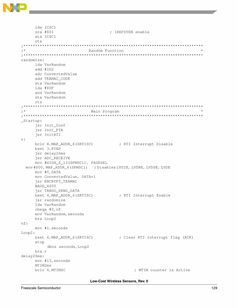
Low-Cost Wireless Sensors, Rev. 0
Freescale Semiconductor 129
lda ICSC1 ora #$01 ; IREFSTEN enable sta ICSC1 rts ;*****************************************************************************;* Random Function *;*****************************************************************************randomize: lda VarRandom add #ID2 adc ConvertedValue add TEAMAC_CODE sta VarRandom lda #$0F and VarRandom sta VarRandom rts;*****************************************************************************;* Main Program *;*****************************************************************************_Startup: jsr Init_Conf jsr Init_PTA jsr InitRTI r: bclr 4,MAP_ADDR_6(SRTISC) ; RTI Interrupt Disable bset 3,PTAD jsr delay26ms jsr ADC_RECEIVE mov #HIGH_6_13(SPMSC1), PAGESEL mov #$00, MAP_ADDR_6(SPMSC1) ; Disables LVDIE, LVDRE, LVDSE, LVDE mov #0,DATA mov ConvertedValue, DATA+1 jsr ENCRYPT_TEAMAC BAUD_4600 jsr TANGO_SEND_DATA bset 4,MAP_ADDR_6(SRTISC) ; RTI Interrupt Enable jsr randomize lda VarRandom cbeqa #0,nZ mov VarRandom,seconds bra Loop2nZ: mov #1,seconds Loop2: bset 6,MAP_ADDR_6(SRTISC) ; Clear RTI interrupt flag (ACK) stop
dbnz seconds,Loop2 bra rdelay26ms: mov #13,seconds MTIM2ms bclr 4,MTIMSC ; MTIM counter is Active
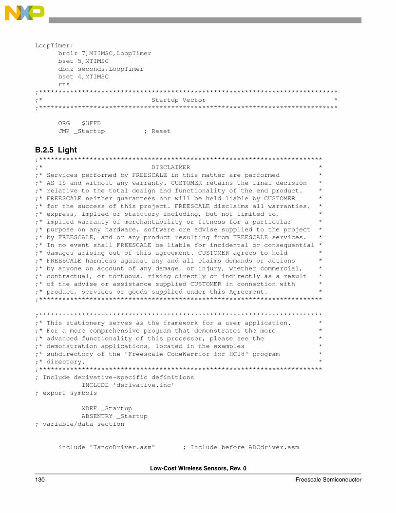
Low-Cost Wireless Sensors, Rev. 0
130 Freescale Semiconductor
LoopTimer: brclr 7,MTIMSC,LoopTimer bset 5,MTIMSC dbnz seconds,LoopTimer bset 4,MTIMSC rts;*****************************************************************************;* Startup Vector *;***************************************************************************** ORG $3FFD JMP _Startup ; Reset
B.2.5 Light;*************************************************************************;* DISCLAIMER *;* Services performed by FREESCALE in this matter are performed *;* AS IS and without any warranty. CUSTOMER retains the final decision *;* relative to the total design and functionality of the end product. *;* FREESCALE neither guarantees nor will be held liable by CUSTOMER *;* for the success of this project. FREESCALE disclaims all warranties, *;* express, implied or statutory including, but not limited to, *;* implied warranty of merchantability or fitness for a particular *;* purpose on any hardware, software ore advise supplied to the project *;* by FREESCALE, and or any product resulting from FREESCALE services. *;* In no event shall FREESCALE be liable for incidental or consequential *;* damages arising out of this agreement. CUSTOMER agrees to hold *;* FREESCALE harmless against any and all claims demands or actions *;* by anyone on account of any damage, or injury, whether commercial, *;* contractual, or tortuous, rising directly or indirectly as a result *;* of the advise or assistance supplied CUSTOMER in connection with *;* product, services or goods supplied under this Agreement. *;*************************************************************************
;*************************************************************************;* This stationery serves as the framework for a user application. *;* For a more comprehensive program that demonstrates the more *;* advanced functionality of this processor, please see the *;* demonstration applications, located in the examples *;* subdirectory of the "Freescale CodeWarrior for HC08" program *;* directory. *;*************************************************************************; Include derivative-specific definitions INCLUDE 'derivative.inc'; export symbols
XDEF _Startup ABSENTRY _Startup; variable/data section
include "TangoDriver.asm" ; Include before ADCdriver.asm
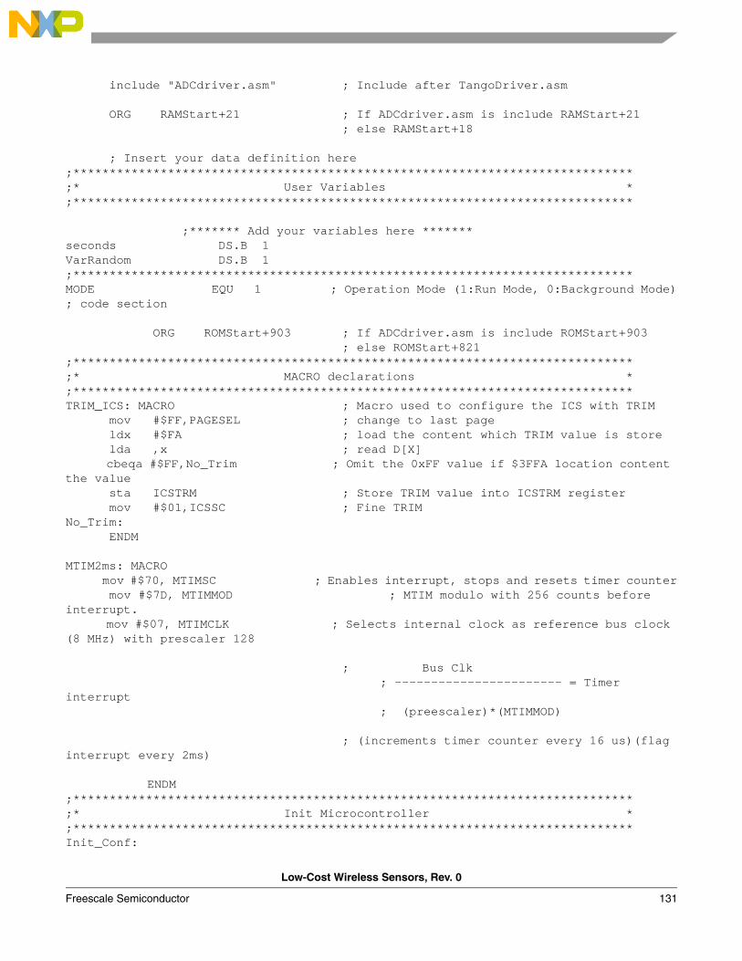
Low-Cost Wireless Sensors, Rev. 0
Freescale Semiconductor 131
include "ADCdriver.asm" ; Include after TangoDriver.asm ORG RAMStart+21 ; If ADCdriver.asm is include RAMStart+21 ; else RAMStart+18 ; Insert your data definition here;*****************************************************************************;* User Variables *;***************************************************************************** ;******* Add your variables here *******seconds DS.B 1VarRandom DS.B 1;*****************************************************************************MODE EQU 1 ; Operation Mode (1:Run Mode, 0:Background Mode); code section
ORG ROMStart+903 ; If ADCdriver.asm is include ROMStart+903 ; else ROMStart+821;*****************************************************************************;* MACRO declarations *;*****************************************************************************TRIM_ICS: MACRO ; Macro used to configure the ICS with TRIM mov #$FF,PAGESEL ; change to last page ldx #$FA ; load the content which TRIM value is store lda ,x ; read D[X] cbeqa #$FF,No_Trim ; Omit the 0xFF value if $3FFA location content the value sta ICSTRM ; Store TRIM value into ICSTRM register mov #$01,ICSSC ; Fine TRIM No_Trim: ENDM MTIM2ms: MACRO mov #$70, MTIMSC ; Enables interrupt, stops and resets timer counter mov #$7D, MTIMMOD ; MTIM modulo with 256 counts before interrupt. mov #$07, MTIMCLK ; Selects internal clock as reference bus clock (8 MHz) with prescaler 128 ; Bus Clk
; ----------------------- = Timer interrupt
; (preescaler)*(MTIMMOD)
; (increments timer counter every 16 us)(flag interrupt every 2ms)
ENDM ;*****************************************************************************;* Init Microcontroller *;*****************************************************************************Init_Conf:
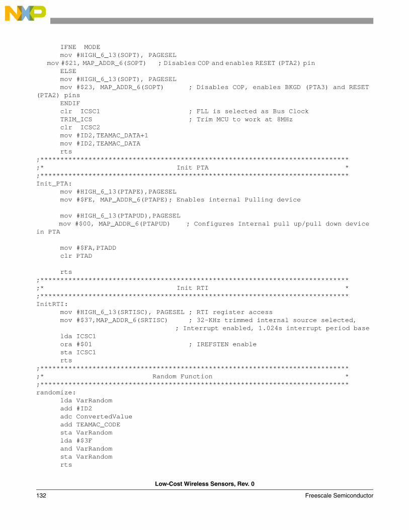
Low-Cost Wireless Sensors, Rev. 0
132 Freescale Semiconductor
IFNE MODE mov #HIGH_6_13(SOPT), PAGESEL mov #$21, MAP_ADDR_6(SOPT) ; Disables COP and enables RESET (PTA2) pin ELSE mov #HIGH_6_13(SOPT), PAGESEL mov #$23, MAP_ADDR_6(SOPT) ; Disables COP, enables BKGD (PTA3) and RESET (PTA2) pins ENDIF clr ICSC1 ; FLL is selected as Bus Clock TRIM_ICS ; Trim MCU to work at 8MHz clr ICSC2 mov #ID2,TEAMAC_DATA+1 mov #ID2,TEAMAC_DATA rts;*****************************************************************************;* Init PTA *;*****************************************************************************Init_PTA: mov #HIGH_6_13(PTAPE),PAGESEL mov #$FE, MAP_ADDR_6(PTAPE); Enables internal Pulling device mov #HIGH_6_13(PTAPUD),PAGESEL mov #$00, MAP_ADDR_6(PTAPUD) ; Configures Internal pull up/pull down device in PTA mov #$FA,PTADD clr PTAD rts;*****************************************************************************;* Init RTI *;*****************************************************************************InitRTI: mov #HIGH_6_13(SRTISC), PAGESEL ; RTI register access mov #$37,MAP_ADDR_6(SRTISC) ; 32-KHz trimmed internal source selected, ; Interrupt enabled, 1.024s interrupt period base lda ICSC1 ora #$01 ; IREFSTEN enable sta ICSC1 rts ;*****************************************************************************;* Random Function *;*****************************************************************************randomize: lda VarRandom add #ID2 adc ConvertedValue add TEAMAC_CODE sta VarRandom lda #$3F and VarRandom sta VarRandom rts
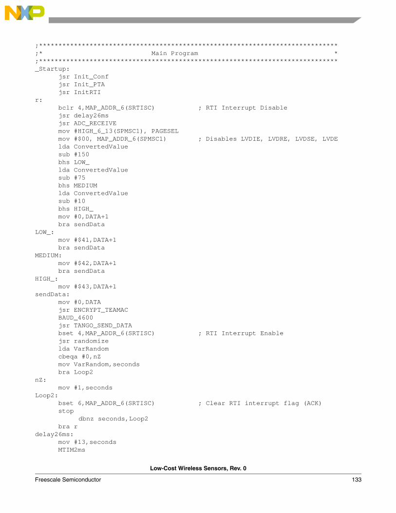
Low-Cost Wireless Sensors, Rev. 0
Freescale Semiconductor 133
;*****************************************************************************;* Main Program *;*****************************************************************************_Startup: jsr Init_Conf jsr Init_PTA jsr InitRTI r: bclr 4,MAP_ADDR_6(SRTISC) ; RTI Interrupt Disable jsr delay26ms jsr ADC_RECEIVE mov #HIGH_6_13(SPMSC1), PAGESEL mov #$00, MAP_ADDR_6(SPMSC1) ; Disables LVDIE, LVDRE, LVDSE, LVDE lda ConvertedValue sub #150 bhs LOW_ lda ConvertedValue sub #75 bhs MEDIUM lda ConvertedValue sub #10 bhs HIGH_ mov #0,DATA+1 bra sendData LOW_: mov #$41,DATA+1 bra sendDataMEDIUM: mov #$42,DATA+1 bra sendDataHIGH_: mov #$43,DATA+1sendData: mov #0,DATA jsr ENCRYPT_TEAMAC BAUD_4600 jsr TANGO_SEND_DATA bset 4,MAP_ADDR_6(SRTISC) ; RTI Interrupt Enable jsr randomize lda VarRandom cbeqa #0,nZ mov VarRandom,seconds bra Loop2nZ: mov #1,seconds Loop2: bset 6,MAP_ADDR_6(SRTISC) ; Clear RTI interrupt flag (ACK) stop
dbnz seconds,Loop2 bra rdelay26ms: mov #13,seconds MTIM2ms
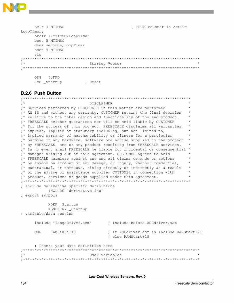
Low-Cost Wireless Sensors, Rev. 0
134 Freescale Semiconductor
bclr 4,MTIMSC ; MTIM counter is ActiveLoopTimer: brclr 7,MTIMSC,LoopTimer bset 5,MTIMSC dbnz seconds,LoopTimer bset 4,MTIMSC rts;*****************************************************************************;* Startup Vector *;***************************************************************************** ORG $3FFD JMP _Startup ; Reset
B.2.6 Push Button;*************************************************************************;* DISCLAIMER *;* Services performed by FREESCALE in this matter are performed *;* AS IS and without any warranty. CUSTOMER retains the final decision *;* relative to the total design and functionality of the end product. *;* FREESCALE neither guarantees nor will be held liable by CUSTOMER *;* for the success of this project. FREESCALE disclaims all warranties, *;* express, implied or statutory including, but not limited to, *;* implied warranty of merchantability or fitness for a particular *;* purpose on any hardware, software ore advise supplied to the project *;* by FREESCALE, and or any product resulting from FREESCALE services. *;* In no event shall FREESCALE be liable for incidental or consequential *;* damages arising out of this agreement. CUSTOMER agrees to hold *;* FREESCALE harmless against any and all claims demands or actions *;* by anyone on account of any damage, or injury, whether commercial, *;* contractual, or tortuous, rising directly or indirectly as a result *;* of the advise or assistance supplied CUSTOMER in connection with *;* product, services or goods supplied under this Agreement. *;*************************************************************************; Include derivative-specific definitions INCLUDE 'derivative.inc'; export symbols
XDEF _Startup ABSENTRY _Startup; variable/data section
include "TangoDriver.asm" ; Include before ADCdriver.asm ORG RAMStart+18 ; If ADCdriver.asm is include RAMStart+21 ; else RAMStart+18 ; Insert your data definition here;*****************************************************************************;* User Variables *;*****************************************************************************
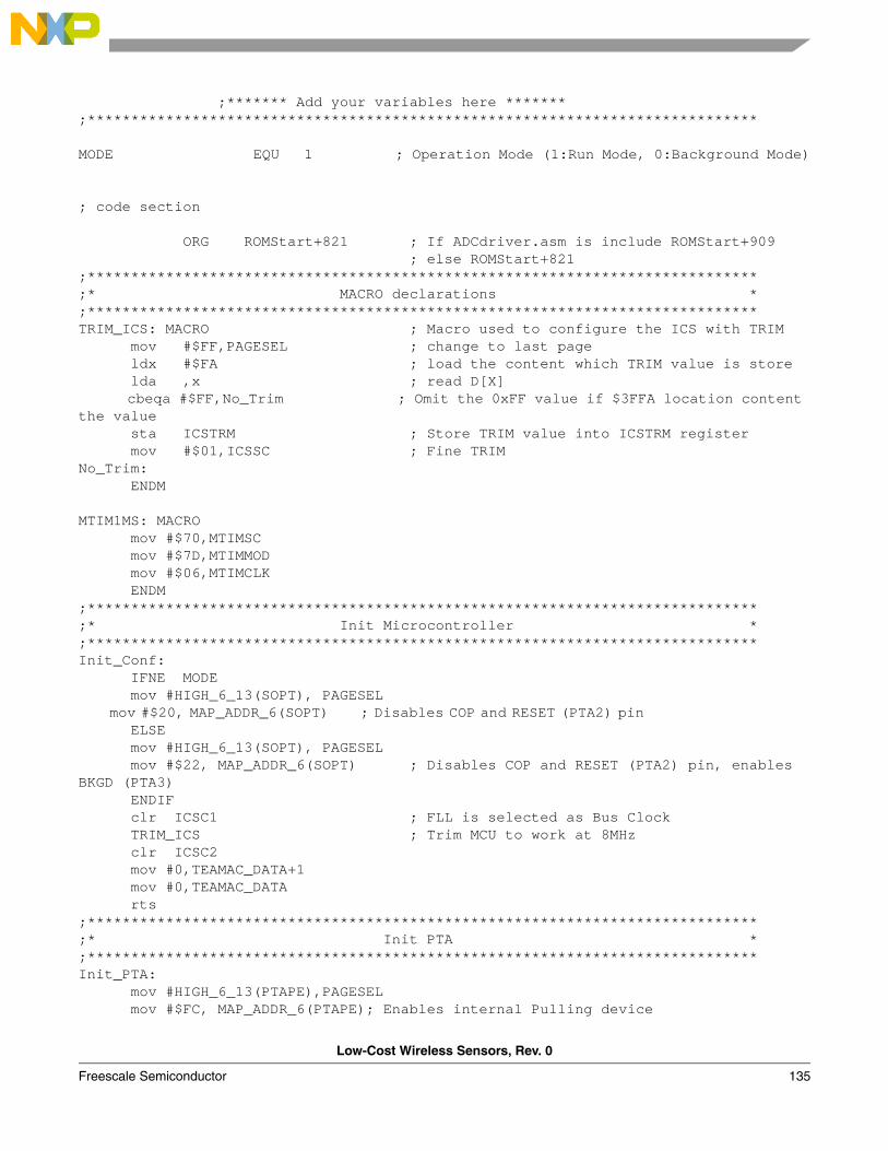
Low-Cost Wireless Sensors, Rev. 0
Freescale Semiconductor 135
;******* Add your variables here ******* ;***************************************************************************** MODE EQU 1 ; Operation Mode (1:Run Mode, 0:Background Mode)
; code section
ORG ROMStart+821 ; If ADCdriver.asm is include ROMStart+909 ; else ROMStart+821;*****************************************************************************;* MACRO declarations *;*****************************************************************************TRIM_ICS: MACRO ; Macro used to configure the ICS with TRIM mov #$FF,PAGESEL ; change to last page ldx #$FA ; load the content which TRIM value is store lda ,x ; read D[X] cbeqa #$FF,No_Trim ; Omit the 0xFF value if $3FFA location content the value sta ICSTRM ; Store TRIM value into ICSTRM register mov #$01,ICSSC ; Fine TRIM No_Trim: ENDM MTIM1MS: MACRO mov #$70,MTIMSC mov #$7D,MTIMMOD mov #$06,MTIMCLK ENDM ;*****************************************************************************;* Init Microcontroller *;*****************************************************************************Init_Conf: IFNE MODE mov #HIGH_6_13(SOPT), PAGESEL mov #$20, MAP_ADDR_6(SOPT) ; Disables COP and RESET (PTA2) pin ELSE mov #HIGH_6_13(SOPT), PAGESEL mov #$22, MAP_ADDR_6(SOPT) ; Disables COP and RESET (PTA2) pin, enables BKGD (PTA3) ENDIF clr ICSC1 ; FLL is selected as Bus Clock TRIM_ICS ; Trim MCU to work at 8MHz clr ICSC2 mov #0,TEAMAC_DATA+1 mov #0,TEAMAC_DATA rts;*****************************************************************************;* Init PTA *;*****************************************************************************Init_PTA: mov #HIGH_6_13(PTAPE),PAGESEL mov #$FC, MAP_ADDR_6(PTAPE); Enables internal Pulling device
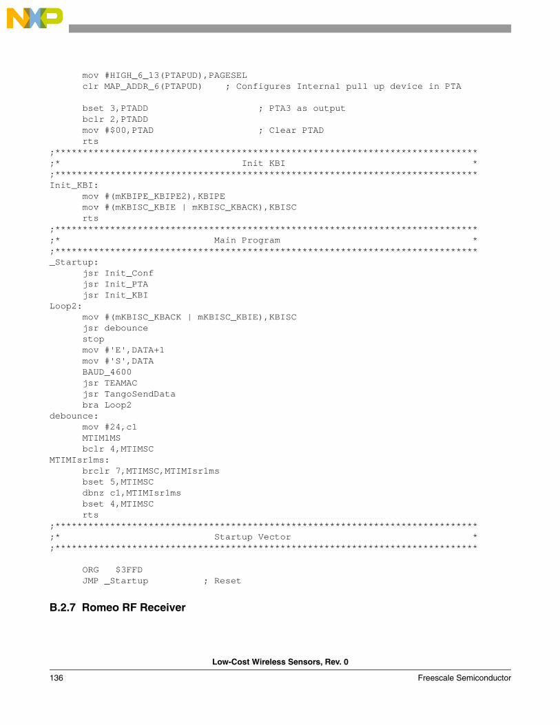
Low-Cost Wireless Sensors, Rev. 0
136 Freescale Semiconductor
mov #HIGH_6_13(PTAPUD),PAGESEL clr MAP_ADDR_6(PTAPUD) ; Configures Internal pull up device in PTA bset 3,PTADD ; PTA3 as output bclr 2,PTADD mov #$00,PTAD ; Clear PTAD rts;*****************************************************************************;* Init KBI *;*****************************************************************************Init_KBI: mov #(mKBIPE_KBIPE2),KBIPE mov #(mKBISC_KBIE | mKBISC_KBACK),KBISC rts ;*****************************************************************************;* Main Program *;*****************************************************************************_Startup: jsr Init_Conf jsr Init_PTA jsr Init_KBILoop2: mov #(mKBISC_KBACK | mKBISC_KBIE),KBISC jsr debounce stop mov #'E',DATA+1 mov #'S',DATA BAUD_4600 jsr TEAMAC jsr TangoSendData bra Loop2debounce: mov #24,c1 MTIM1MS bclr 4,MTIMSC MTIMIsr1ms: brclr 7,MTIMSC,MTIMIsr1ms bset 5,MTIMSC dbnz c1,MTIMIsr1ms bset 4,MTIMSC rts;*****************************************************************************;* Startup Vector *;***************************************************************************** ORG $3FFD JMP _Startup ; Reset
B.2.7 Romeo RF Receiver
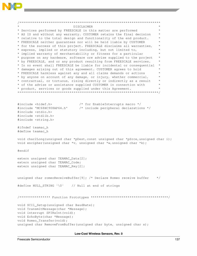
Low-Cost Wireless Sensors, Rev. 0
Freescale Semiconductor 137
/************************************************************************** DISCLAIMER ** Services performed by FREESCALE in this matter are performed ** AS IS and without any warranty. CUSTOMER retains the final decision ** relative to the total design and functionality of the end product. ** FREESCALE neither guarantees nor will be held liable by CUSTOMER ** for the success of this project. FREESCALE disclaims all warranties, ** express, implied or statutory including, but not limited to, ** implied warranty of merchantability or fitness for a particular ** purpose on any hardware, software ore advise supplied to the project ** by FREESCALE, and or any product resulting from FREESCALE services. ** In no event shall FREESCALE be liable for incidental or consequential ** damages arising out of this agreement. CUSTOMER agrees to hold ** FREESCALE harmless against any and all claims demands or actions ** by anyone on account of any damage, or injury, whether commercial, ** contractual, or tortuous, rising directly or indirectly as a result ** of the advise or assistance supplied CUSTOMER in connection with ** product, services or goods supplied under this Agreement. **************************************************************************/
#include <hidef.h> /* for EnableInterrupts macro */#include "MC68HC908AP64.h" /* include peripheral declarations */#include <stdio.h>#include <stdlib.h>#include <string.h>
#ifndef teamac_h#define teamac_h
void char2Long(unsigned char *pDest,const unsigned char *pSrce,unsigned char i);void encipher(unsigned char *v, unsigned char *w,unsigned char *k);
#endif
extern unsigned char TEAMAC_Data[2];extern unsigned char TEAMAC_Code;extern unsigned char TEAMAC_Key[2];
unsigned char romeoReceiveBuffer[9]; /* Declare Romeo receive buffer */
#define NULL_STRING '\0' // Null at end of strings
/**************** Function Prototypes ****************************************/
void SCI1_Setup(unsigned char BaudRate);void TransmitMessage(char *Message);void interrupt SPIRxInt(void);void EchoByte(char *Message);void Romeo_Transfer(void);unsigned char RemoveFromBuffer(unsigned char byte, unsigned char x);
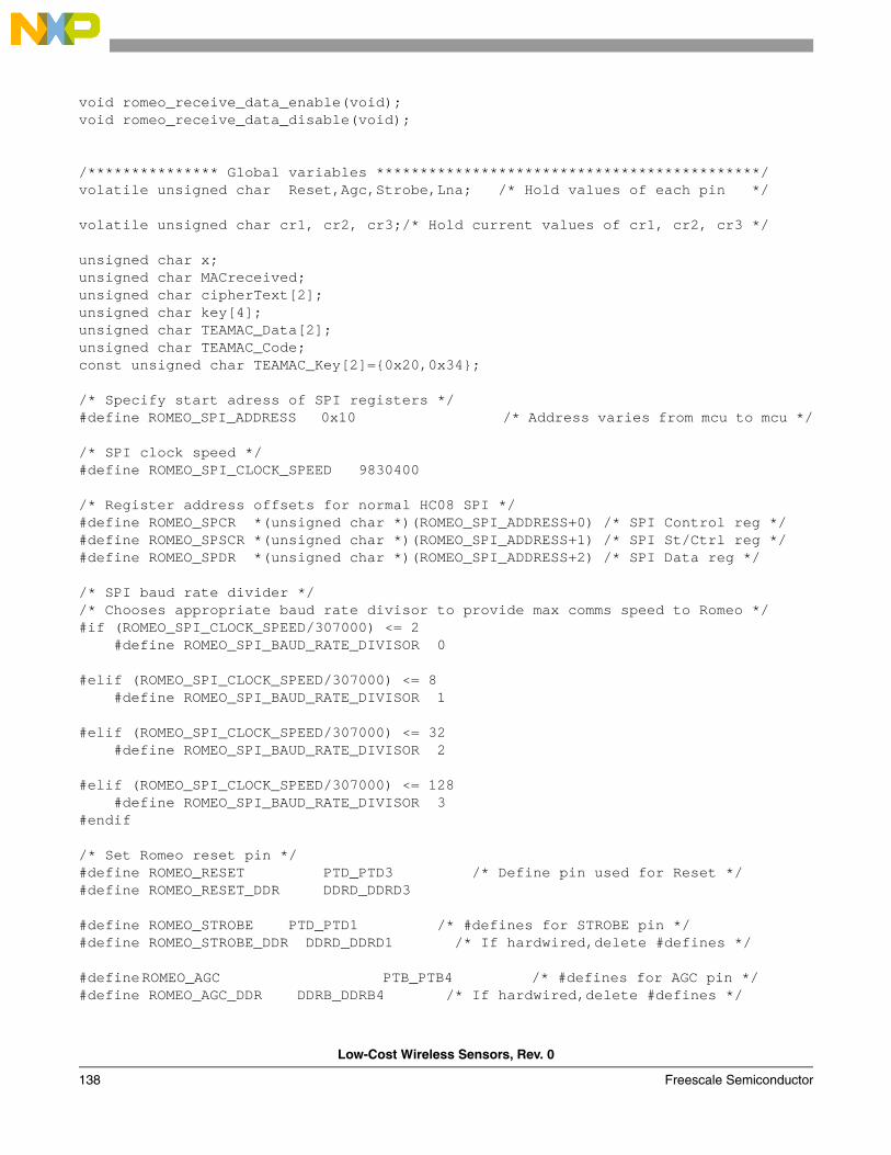
Low-Cost Wireless Sensors, Rev. 0
138 Freescale Semiconductor
void romeo_receive_data_enable(void);void romeo_receive_data_disable(void);
/*************** Global variables ********************************************/volatile unsigned char Reset,Agc,Strobe,Lna; /* Hold values of each pin */
volatile unsigned char cr1, cr2, cr3;/* Hold current values of cr1, cr2, cr3 */
unsigned char x;unsigned char MACreceived;unsigned char cipherText[2];unsigned char key[4]; unsigned char TEAMAC_Data[2];unsigned char TEAMAC_Code;const unsigned char TEAMAC_Key[2]=0x20,0x34; /* Specify start adress of SPI registers */#define ROMEO_SPI_ADDRESS 0x10 /* Address varies from mcu to mcu */
/* SPI clock speed */#define ROMEO_SPI_CLOCK_SPEED 9830400
/* Register address offsets for normal HC08 SPI */#define ROMEO_SPCR *(unsigned char *)(ROMEO_SPI_ADDRESS+0) /* SPI Control reg */#define ROMEO_SPSCR *(unsigned char *)(ROMEO_SPI_ADDRESS+1) /* SPI St/Ctrl reg */#define ROMEO_SPDR *(unsigned char *)(ROMEO_SPI_ADDRESS+2) /* SPI Data reg */
/* SPI baud rate divider *//* Chooses appropriate baud rate divisor to provide max comms speed to Romeo */#if (ROMEO_SPI_CLOCK_SPEED/307000) <= 2 #define ROMEO_SPI_BAUD_RATE_DIVISOR 0
#elif (ROMEO_SPI_CLOCK_SPEED/307000) <= 8 #define ROMEO_SPI_BAUD_RATE_DIVISOR 1
#elif (ROMEO_SPI_CLOCK_SPEED/307000) <= 32 #define ROMEO_SPI_BAUD_RATE_DIVISOR 2
#elif (ROMEO_SPI_CLOCK_SPEED/307000) <= 128 #define ROMEO_SPI_BAUD_RATE_DIVISOR 3#endif
/* Set Romeo reset pin */ #define ROMEO_RESET PTD_PTD3 /* Define pin used for Reset */#define ROMEO_RESET_DDR DDRD_DDRD3
#define ROMEO_STROBE PTD_PTD1 /* #defines for STROBE pin */#define ROMEO_STROBE_DDR DDRD_DDRD1 /* If hardwired,delete #defines */
#defineROMEO_AGC PTB_PTB4 /* #defines for AGC pin */#define ROMEO_AGC_DDR DDRB_DDRB4 /* If hardwired,delete #defines */
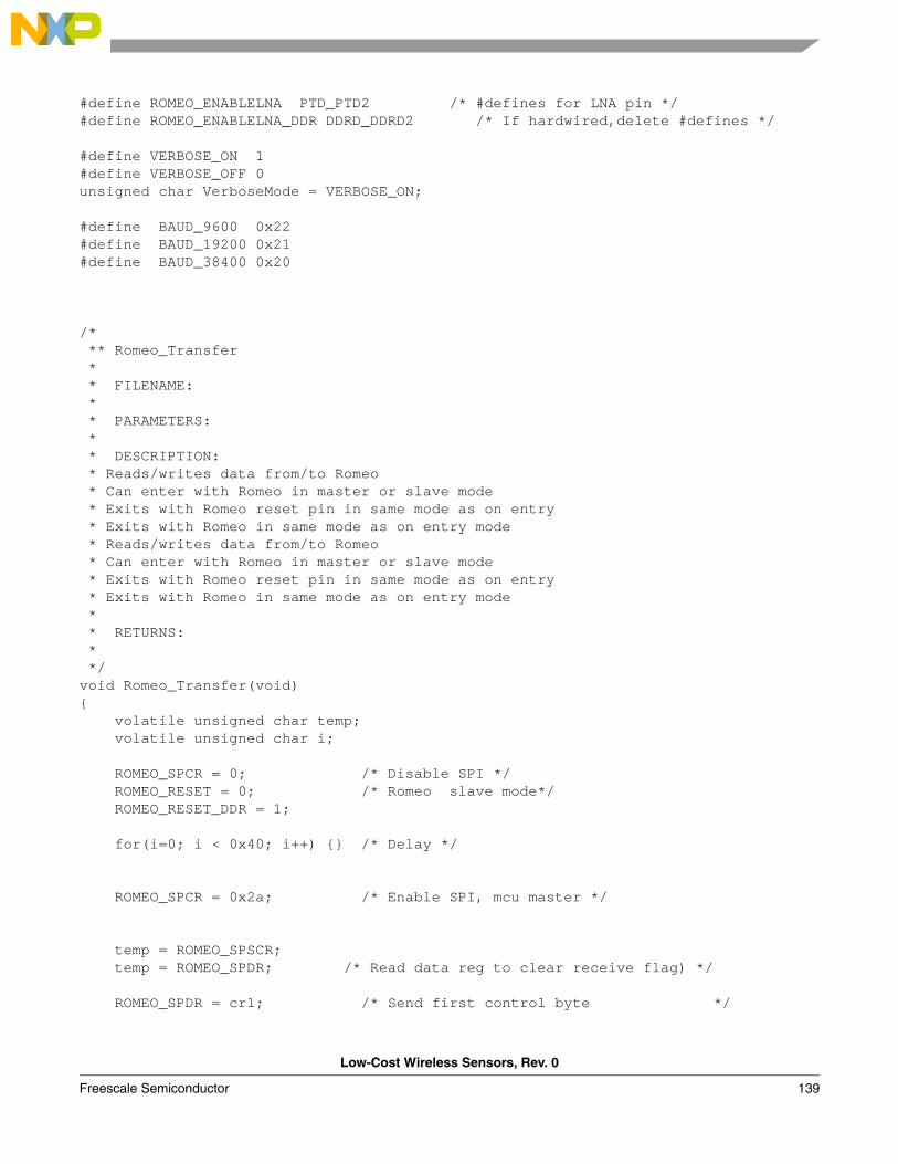
Low-Cost Wireless Sensors, Rev. 0
Freescale Semiconductor 139
#define ROMEO_ENABLELNA PTD_PTD2 /* #defines for LNA pin */#define ROMEO_ENABLELNA_DDR DDRD_DDRD2 /* If hardwired,delete #defines */
#define VERBOSE_ON 1#define VERBOSE_OFF 0unsigned char VerboseMode = VERBOSE_ON;
#define BAUD_9600 0x22#define BAUD_19200 0x21#define BAUD_38400 0x20
/* ** Romeo_Transfer * * FILENAME: * * PARAMETERS: * * DESCRIPTION: * Reads/writes data from/to Romeo * Can enter with Romeo in master or slave mode * Exits with Romeo reset pin in same mode as on entry * Exits with Romeo in same mode as on entry mode * Reads/writes data from/to Romeo * Can enter with Romeo in master or slave mode * Exits with Romeo reset pin in same mode as on entry * Exits with Romeo in same mode as on entry mode * * RETURNS: * */void Romeo_Transfer(void) volatile unsigned char temp; volatile unsigned char i;
ROMEO_SPCR = 0; /* Disable SPI */ ROMEO_RESET = 0; /* Romeo slave mode*/ ROMEO_RESET_DDR = 1;
for(i=0; i < 0x40; i++) /* Delay */
ROMEO_SPCR = 0x2a; /* Enable SPI, mcu master */
temp = ROMEO_SPSCR; temp = ROMEO_SPDR; /* Read data reg to clear receive flag) */
ROMEO_SPDR = cr1; /* Send first control byte */
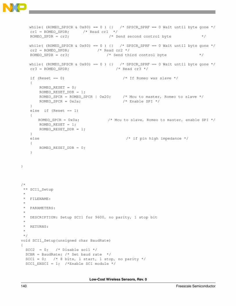
Low-Cost Wireless Sensors, Rev. 0
140 Freescale Semiconductor
while( (ROMEO_SPSCR & 0x80) == 0 ) /* SPSCR_SPRF == 0 Wait until byte gone */ cr1 = ROMEO_SPDR; /* Read cr1 */ ROMEO_SPDR = cr2; /* Send second control byte */
while( (ROMEO_SPSCR & 0x80) == 0 ) /* SPSCR_SPRF == 0 Wait until byte gone */ cr2 = ROMEO_SPDR; /* Read cr2 */ ROMEO_SPDR = cr3; /* Send third control byte */
while( (ROMEO_SPSCR & 0x80) == 0 ) /* SPSCR_SPRF == 0 Wait until byte gone */ cr3 = ROMEO_SPDR; /* Read cr3 */ if (Reset == 0) /* If Romeo was slave */ ROMEO_RESET = 0; ROMEO_RESET_DDR = 1; ROMEO_SPCR = ROMEO_SPCR | 0x20; /* Mcu to master, Romeo to slave */ ROMEO_SPCR = 0x2a; /* Enable SPI */ else if (Reset == 1) ROMEO_SPCR = 0x0a; /* Mcu to slave, Romeo to master, enable SPI */ ROMEO_RESET = 1; ROMEO_RESET_DDR = 1; else /* if pin high impedance */ ROMEO_RESET_DDR = 0;
/* ** SCI1_Setup * * FILENAME: * * PARAMETERS: * * DESCRIPTION: Setup SCI1 for 9600, no parity, 1 stop bit * * RETURNS: * */void SCI1_Setup(unsigned char BaudRate) SCC2 = 0; /* Disable sci1 */ SCBR = BaudRate; /* Set baud rate */ SCC1 = 0; /* 8 bits, 1 start, 1 stop, no parity */ SCC1_ENSCI = 1; /*Enable SCI module */
Low-Cost Wireless Sensors, Rev. 0
Freescale Semiconductor 141
SCC2_SCRIE = 1; /* Enable receive ints */ SCC2_TE = 1; /* Enable tx */ //SCC2_RE = 1; /* Enable rx */
void TransmitMessage(char *Message) volatile char temp; temp = SCS1; while(*Message != NULL_STRING) SCDR = *Message; while ( SCS1_TC != 1) //Loop until byte sent temp = SCS1; //Read byte to clear tc flag Message++;
** SPIRxInt * * FILENAME: * * PARAMETERS: * * DESCRIPTION: Reads received byte from SPI into Buffer * * RETURNS: * */interrupt void SPIRxInt(void) romeoReceiveBuffer[x] = ROMEO_SPSCR;/* Read control reg with sprf flag set */ romeoReceiveBuffer[x] = ROMEO_SPDR;/* Read data from SPI */ x++;
/* ** EchoByte * * FILENAME: * * PARAMETERS: * * DESCRIPTION: Writes byte to SCI * * RETURNS: * */void EchoByte(char *Message) volatile char temp; temp = SCS1; SCDR = *Message ;
Low-Cost Wireless Sensors, Rev. 0
142 Freescale Semiconductor
while (SCS1_TC != 1) //Loop until byte sent temp = SCS1; //Read byte to clear tc flag
/* ** AddToBuffer * * FILENAME: * * PARAMETERS: * * DESCRIPTION: Take byte and add binary equivilent to buffer as ascii text * For example, if byte = 0x55, '01010101' is added to buffer * * RETURNS: * */unsigned char RemoveFromBuffer(unsigned char byte, unsigned char x) unsigned char i; for(i=0; i<8;i++) if ( (byte & 0x01) != 0 ) romeoReceiveBuffer[x] |= 0x01; else romeoReceiveBuffer[x] |= 0x00; if (i<=6) romeoReceiveBuffer[x] <<=1; /* Shift byte left */ else romeoReceiveBuffer[x]=romeoReceiveBuffer[x]; byte >>= 1; /* Shift byte right */ return romeoReceiveBuffer[x];
/* Receive data from romeo enable */void romeo_receive_data_enable(void) unsigned char temp; ROMEO_SPCR = ROMEO_SPCR & 0xdd; /* clear spe and spmstr */ ROMEO_SPCR = ROMEO_SPCR | 0x02; /* SPCR_SPE = 1 */ ROMEO_SPCR = ROMEO_SPCR | 0x80; /* SPCR_SPRIE = 1 enable SPI receive ints */ for(temp=0; temp < 0x40; temp++) /* Delay */ temp = ROMEO_SPSCR; temp = ROMEO_SPDR;
/* Receive data from romeo disable */
Low-Cost Wireless Sensors, Rev. 0
Freescale Semiconductor 143
void romeo_receive_data_disable(void) unsigned char temp; ROMEO_SPCR = ROMEO_SPCR & 0xfd; /*SPE = 0*/ ROMEO_SPCR = ROMEO_SPCR & 0x7f; /*SPCR_SPRIE = 0*/
for(temp=0; temp < 0x40; temp++)
void char2Long(unsigned char *pDest,const unsigned char *pSrce,unsigned char i) *pDest = 0; if (i==0) *pDest |= (*pSrce & 0x03); *pDest <<= 2; *pDest |= ((*pSrce & 0x0C)>>2); *pDest <<= 2; *pDest |= ((*pSrce & 0x30)>>4); *pDest <<= 2; *pDest |= ((*pSrce & 0xC0)>>6); if (i==1) *pDest |= ((*pSrce & 0x0C)>>2); *pDest <<= 2; *pDest |= ((*pSrce & 0x30)>>4); *pDest <<= 2; *pDest |= ((*pSrce & 0xC0)>>6); *pDest <<= 2; *pDest |= (*(pSrce+1) & 0x03); if (i==2) *pDest |= ((*pSrce & 0x30)>>4); *pDest <<= 2; *pDest |= ((*pSrce & 0xC0)>>6); *pDest <<= 2; *pDest |= (*(pSrce+1) & 0x03); *pDest <<= 2; *pDest |= ((*(pSrce+1) & 0x0C)>>2); if (i==4) *pDest |= (*(pSrce+1) & 0x03); *pDest <<= 2; *pDest |= ((*(pSrce+1) & 0x0C)>>2); *pDest <<= 2; *pDest |= ((*(pSrce+1) & 0x30)>>4); *pDest <<= 2; *pDest |= ((*(pSrce+1) & 0xC0)>>6);
Low-Cost Wireless Sensors, Rev. 0
144 Freescale Semiconductor
void encipher(unsigned char *v,unsigned char *w,unsigned char *k)
unsigned char y, z, sum, delta;unsigned char n;
y=*v;z=*(v+1);sum=0;n=8;delta=0x9E;
while(n-- > 0)y += (((z << 4) ^ (z >> 5)) + z) ^ (sum + k[sum&3]);sum += delta;z += (((y << 4) ^ (y >> 5)) + y) ^ (sum + k[(sum>>3) & 3]);
w[0]=y; w[1]=z;
/* ** main * * FILENAME: * * PARAMETERS: * * DESCRIPTION: Main program loop * * RETURNS: * */ void main(void)
//unsigned char temp;
CONFIG1 = 0x03; /* Disable COP, enable STOP instruction */ SCI1_Setup(BAUD_19200);
VerboseMode = VERBOSE_ON;
ROMEO_SPSCR = ROMEO_SPI_BAUD_RATE_DIVISOR; /* Initialise SPI */
Reset = 1; /* Reset = 1 (Romeo is master) */
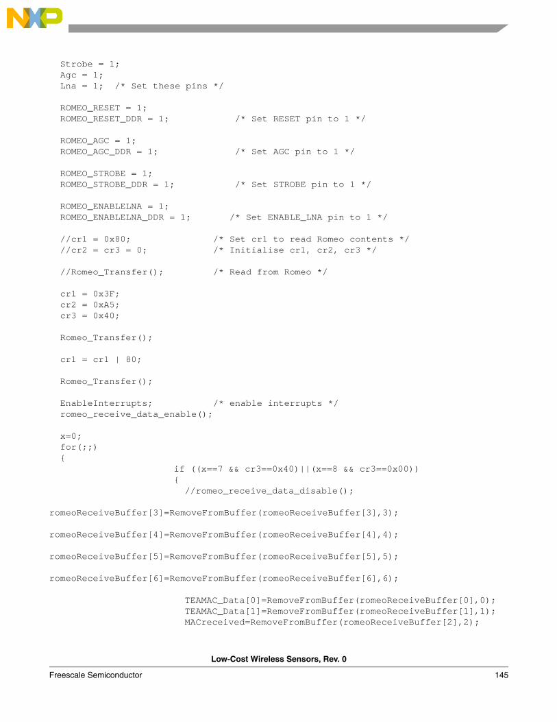
Low-Cost Wireless Sensors, Rev. 0
Freescale Semiconductor 145
Strobe = 1; Agc = 1; Lna = 1; /* Set these pins */
ROMEO_RESET = 1; ROMEO_RESET_DDR = 1; /* Set RESET pin to 1 */ ROMEO_AGC = 1; ROMEO_AGC_DDR = 1; /* Set AGC pin to 1 */ ROMEO_STROBE = 1; ROMEO_STROBE_DDR = 1; /* Set STROBE pin to 1 */ ROMEO_ENABLELNA = 1; ROMEO_ENABLELNA_DDR = 1; /* Set ENABLE_LNA pin to 1 */ //cr1 = 0x80; /* Set cr1 to read Romeo contents */ //cr2 = cr3 = 0; /* Initialise cr1, cr2, cr3 */ //Romeo_Transfer(); /* Read from Romeo */
cr1 = 0x3F; cr2 = 0xA5; cr3 = 0x40; Romeo_Transfer(); cr1 = cr1 | 80; Romeo_Transfer(); EnableInterrupts; /* enable interrupts */ romeo_receive_data_enable(); x=0; for(;;) if ((x==7 && cr3==0x40)||(x==8 && cr3==0x00)) //romeo_receive_data_disable(); romeoReceiveBuffer[3]=RemoveFromBuffer(romeoReceiveBuffer[3],3); romeoReceiveBuffer[4]=RemoveFromBuffer(romeoReceiveBuffer[4],4); romeoReceiveBuffer[5]=RemoveFromBuffer(romeoReceiveBuffer[5],5); romeoReceiveBuffer[6]=RemoveFromBuffer(romeoReceiveBuffer[6],6); TEAMAC_Data[0]=RemoveFromBuffer(romeoReceiveBuffer[0],0); TEAMAC_Data[1]=RemoveFromBuffer(romeoReceiveBuffer[1],1); MACreceived=RemoveFromBuffer(romeoReceiveBuffer[2],2);
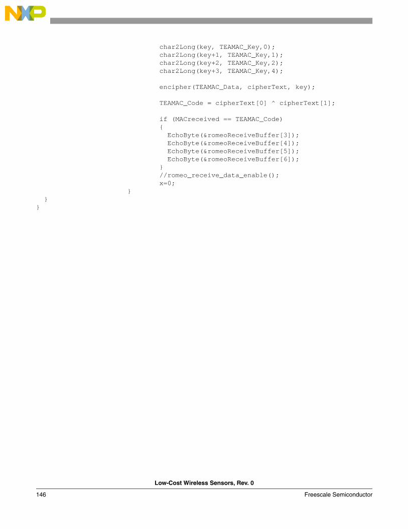
Low-Cost Wireless Sensors, Rev. 0
146 Freescale Semiconductor
char2Long(key, TEAMAC_Key,0); char2Long(key+1, TEAMAC_Key,1); char2Long(key+2, TEAMAC_Key,2); char2Long(key+3, TEAMAC_Key,4);
encipher(TEAMAC_Data, cipherText, key);
TEAMAC_Code = cipherText[0] ^ cipherText[1]; if (MACreceived == TEAMAC_Code) EchoByte(&romeoReceiveBuffer[3]); EchoByte(&romeoReceiveBuffer[4]); EchoByte(&romeoReceiveBuffer[5]); EchoByte(&romeoReceiveBuffer[6]); //romeo_receive_data_enable(); x=0;