Embed Size (px)
Citation preview
LOS Discovery in 3D for Highly DirectionalTransceivers
Mahmudur Khan, Suman Bhunia, Murat Yuksel and Shamik SenguptaDept. of Computer Science and Engineering, University of Nevada, Reno, USA
[email protected], [email protected], [email protected], [email protected]
Abstract—Directional Radio Frequency (RF) / Free-Space-Optical (FSO) transceivers have the potential to play a significantrole in future generation wireless networks. They are advanta-geous in terms of improved spectrum utilization, higher datatransfer rate, and lower probability of interception from un-wanted sources. Despite these advantages, communications usingdirectional transceivers require establishment and maintenanceof line-of-sight (LOS). Thus, establishment of the communicationlink or neighbor discovery plays an important role in mobile adhoc networks with RF/FSO directional transceivers. We considertwo nodes (Unmanned Aerial Vehicles (UAVs) or Quadcopters)hovering in 3D space, each with one directional transceivermounted on a mechanically steerable spherical structure/head,with which they can scan 360o in the horizontal plane and 360o
in the vertical plane. We propose a novel scheme that dealswith the problem of automatic discovery and establishment ofLOS alignment between these nodes. We performed extensivesimulations to show the effectiveness of the proposed neighbordiscovery method. The results show that, using such mechanicallysteerable directional transceivers, it is possible to establish com-munication links to similar neighboring nodes within minimaldiscovery times.
Keywords—Directional; 3D; RF; FSO; Neighbor Discovery; AdHoc; VANET; MANET.
I. INTRODUCTIONThe application of high gain directional antennas have
attracted strong interest from the wireless research communityespecially for mobile ad hoc networks in the recent years[1]-[2]. Directional antennas not only provide higher gain forsignal reception but also makes faster data transfer possiblecompared to the traditional omni-directional ones. Using direc-tional antennas for signal reception reduces interference causedfrom unwanted directions. This directionality further improvesspatial reuse and also lowers the probability of interceptionor detection by sniffers. All these advantages of directionalantennas are suitable for tactical ad hoc networks wheremultiple entities desire to transmit high bandwidth data streamssimultaneously with a requirement of lower interference andreduced probability of being jammed. Equipping UAVs withsuch high-speed directional transceivers can enable a largeset of applications involving transfers of very large wirelessdata. There are many different applications of UAVs, likesurveillance for a military mission (e.g., observation behindthe enemy lines) or a civil mission (e.g., monitoring of atraffic jam or a disaster area, or to broadcast critical data atsome sport events) which require many sensors. UAVs withseveral sensors generate a lot of data which has to be deliveredto either another UAV or a ground station [3]. The higherdata rate required for communication links to transmit moreinformation between UAVs triggered the idea of employinghighly directional transceivers to meet the increasing demand[4].
Although directional transceivers provide the aforemen-tioned benefits, communications using these transceivers are
X
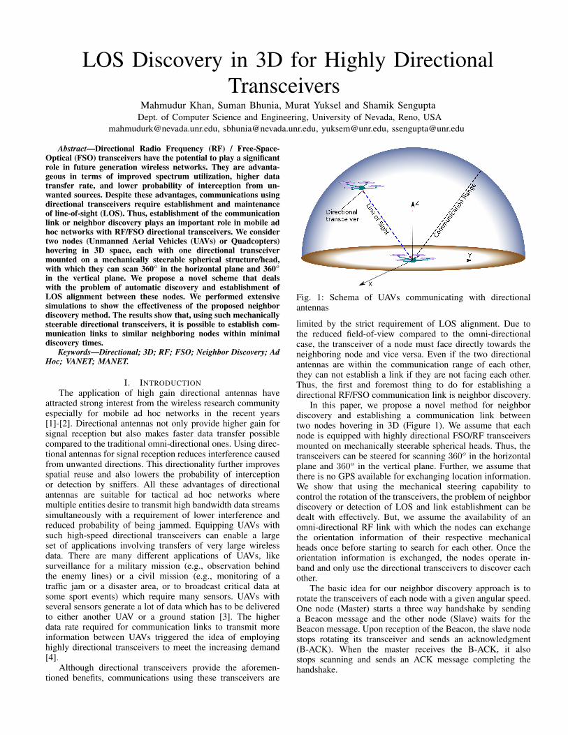
Fig. 1: Schema of UAVs communicating with directionalantennas
limited by the strict requirement of LOS alignment. Due tothe reduced field-of-view compared to the omni-directionalcase, the transceiver of a node must face directly towards theneighboring node and vice versa. Even if the two directionalantennas are within the communication range of each other,they can not establish a link if they are not facing each other.Thus, the first and foremost thing to do for establishing adirectional RF/FSO communication link is neighbor discovery.
In this paper, we propose a novel method for neighbordiscovery and establishing a communication link betweentwo nodes hovering in 3D (Figure 1). We assume that eachnode is equipped with highly directional FSO/RF transceiversmounted on mechanically steerable spherical heads. Thus, thetransceivers can be steered for scanning 360o in the horizontalplane and 360o in the vertical plane. Further, we assume thatthere is no GPS available for exchanging location information.We show that using the mechanical steering capability tocontrol the rotation of the transceivers, the problem of neighbordiscovery or detection of LOS and link establishment can bedealt with effectively. But, we assume the availability of anomni-directional RF link with which the nodes can exchangethe orientation information of their respective mechanicalheads once before starting to search for each other. Once theorientation information is exchanged, the nodes operate in-band and only use the directional transceivers to discover eachother.
The basic idea for our neighbor discovery approach is torotate the transceivers of each node with a given angular speed.One node (Master) starts a three way handshake by sendinga Beacon message and the other node (Slave) waits for theBeacon message. Upon reception of the Beacon, the slave nodestops rotating its transceiver and sends an acknowledgment(B-ACK). When the master receives the B-ACK, it alsostops scanning and sends an ACK message completing thehandshake.

The rest of the paper is organized as follows: Section IIsurveys the relevant background on directional transmissionand neighbor discovery. The proposed methodology, theoret-ical analysis and the algorithms are described in Section III.Section IV illustrates the simulation scenarios and discussesthe results. Finally, Section V concludes the paper.
II. BACKGROUNDIn this section, we first present the motivation for using
directional transceivers in both FSO and RF communications.Then, we discuss existing literature on neighbor discoveryprotocols for directional transmission.
A. Directional Link MaintenanceIn [5], a new technology involving FSO communication
(FSOC) between unmanned aircrafts (e.g., Aquila - UAVdeveloped by Facebook) is proposed, that will help connectareas of the world that currently do not have the Internet infras-tructure. The authors have reported about testing a new laserthat can transmit data at 10 Gbps. A method for establishingan FSO link among nearby balloons with the aid of GPS, anout-of-band RF channel, camera, and communication with aground station is presented in [6]. In [7], the authors useda predicted movement for maintaining optical-communicationlock with nearby ballons, which also uses the availability ofcamera, GPS, and RF. In both of these works, LOS alignmentbetween the communicating nodes is first achieved using GPSinformation or using a camera to localize the neighbor node.During this phase, omni-directional RF communication is used.Only after locating the neighbor node, a pointing mechanismis used to align the FSO transceivers of the neighboring nodes.Then FSO is used only for exchanging data. The opticalwireless link is not used for discovering or maintaining thelink.
Unlike these out-of-band techniques, in [8], we proposedan in-band method that deals with the problem of maintenanceof LOS alignment between two autonomous UAVs movingin 3D with mechanical steering of FSO transceivers. For RF-challenged environments, such in-band techniques that onlyuse the FSO link itself with no dependence on RF-based linksare necessary.
B. Directional Neighbor DiscoveryNeighbor discovery for directional RF has been well ex-
plored. Choudhury et al.[1], [9] have designed a MAC protocolfor ad hoc networks with directional transmitter and omni-directional receivers. An et al.[10] proposed a handshake basedself adaptive neighbor discovery protocol for ad hoc networkswith directional antennas. This paper also considers direc-tional transmitters and omni-directional receivers for neighbordiscovery while frequency of operation is determined on therun. Ramanathan et al.[11] presented UDAAN, the first fullsystem deployment of an ad hoc network utilizing directionalantennas. It uses heartbeat messages to exchange the posi-tion information and uses GPS clock cycle synchronizationfor neighbor discovery. This prototype uses omni-directionalantennas for establishing the connection with new neighbors.
Zhang et al.[2], [12] proposed two algorithms for neighbordiscovery with directional RF communication. Although [2]provides a good analysis on the number of slots required tocomplete the neighbor discovery, the consideration of all nodesusing synchronous slots is not very practical. Pei et al.[13]proposed another neighbor discovery protocol for directional
MANETs based on synchronous search and positional infor-mation available from GPS.
Jakllari et al.[14] is the only earlier work we foundthat uses directional transmitters and receivers. It proposed apolling based MAC protocol for MANETs where all nodes aresynchronized in terms of the polling slots. It allocates slots fordiscovering new neighbors when all nodes in a MANET pointsto random direction and advertise for neighbor discovery. Italso provides a framework to compute neighbor discoverytime. We assume no synchronization among nodes.
Most of the proposed neighbor discovery algorithms con-sider either omni-directional transmission or omni-directionalreception. Also, some studies consider availability of GPS andsome consider that all nodes have prior information aboutneighbors’ position. In this work, we consider the availabilityof an omni-directional RF only for exchanging orientationinformation of the nodes’ heads at the beginning of thedirectional discovery process. A node is neither aware of itsown position nor the neighbor’s position. Once the orientationinformation is exchanged, the RF link becomes inactive andthe nodes use only the directional transceivers for discoveringeach other.
III. THEORYA. Assumptions
We make the following assumptions for our proposedneighbor discovery model:
i) Mode: The mode of communication between the nodescan be either half-duplex or full-duplex. We consideredhalf-duplex communications for this work.
ii) Nodes in 3D: The nodes hover in 3D space and are withinthe communication range of each other.
iii) Directional: Both the transmitter and the receiver of anode face towards the same direction and rotate together.The receiver can receive signal from a neighbor that iswithin its main beam and the transmission beam of theneighbor must face towards it.
iv) Transceiver rotation: The nodes can rotate theirtransceivers 360o in the horizontal plane and 360o in thevertical plane using mechanically steerable heads. Whileperforming neighbor discovery, both nodes rotate in thesame direction on the horizontal plane, i.e., both clockwiseor counterclockwise.
v) Supplementary channel: At the start of the discoveryphase an additional omni-directional RF channel is used.The nodes are not equipped with any location trackingdevice such as GPS.
B. Transceiver Rotation in 3D spaceAs the distance between the transmitter and receiver of
a node is very small compared to the communication range,we use one beam pattern to indicate both the transmissionand field-of-view areas. Figure 2 shows such a beam. Weapproximate the beam with a cone of height r and radiusr tanβ, where r is the maximum communication range of thetransceiver and β is the divergence angle for transmissionsand the angle of field-of-view for receptions.. The orientationof the beam is denoted by r, θ, φ. In this paper we shall usethe Polar and Cartesian coordinates interchangeably and thecorresponding conversion rules are given below.

Fig. 2: Orientation of directional antenna in 3D sphere
r =
√x2 + y2 + z2
θ = arccos(z/r)
φ = arctan(y/x)
⇔
x = r sin θ cosφ
y = r sin θ sinφ
z = r cos θ
(1)
C. Neighbor DiscoveryAs stated earlier, we consider two nodes hovering in 3D
space. There are two main stages in the proposed neighbordiscovery method: i) initialization and ii) 3D scanning.
In the initialization stage, the nodes use their omni-directional transceivers to find the existence of a neighbor nodethrough a common RF channel (very low data rate comparedto directional transceivers). Since we consider the absence ofGPS, the nodes can not share their location information toeach other. In this stage, the nodes agree on a starting time forthe 3D scanning stage to synchronize the discovery process(figure 4). Moreover, one of the nodes (Master) agree to onlytransmit Beacon messages, the other one agrees to act as areceiver (Slave). The master node starts the 3D scanning withits transceiver facing in the upward direction (φ = 0o, θ = 0o).The slave node faces its transceiver downward (φ = 0o ,θ = 180o) at the start of 3D scanning. The nodes decide torotate their transceivers at the same angular speed of ω in thesame direction on the horizontal plane.
After completing the initialization, the nodes stop using thecommon RF channel and progresses to the 3D scanning stage.In this stage, the nodes use only their directional very high datarate RF/FSO transceivers for LOS discovery. The master nodestarts the 3D scanning by rotating its transceiver followinga modified spiral path (explained in Section III-D) as shownin Figure 3a. While rotating the transceiver, it sends a Beaconmessage periodically. The slave node also rotates its transceiverin a similar modified spiral path starting from the bottom endof the sphere. It waits for a Beacon message to arrive fromthe master node. Once a Beacon message is received, it stopsrotating its transceiver and sends an acknowledgment message(B-ACK) to the master. Upon receiving the B-ACK message,the master also stops rotating its transceiver and does notsend anymore Beacon messages. It sends an ACK messageto the slave completing the three-way handshake (figure 4).This completes the neighbor discovery and a communicationlink is established between the nodes.
D. Modified Helix MovementTo make the motor rotation smooth, we consider the
transceiver beams to rotate in a spiral pattern and scanningin the 3D space for discovering the LOS between neighbornodes. Figure 3a ilustrates a sample path taken by the beam.The dotted blue line denotes the path of the normal of the
beam. We consider the range of the beam to be the radiusof the sphere created by the modified spiral. We can simplyimagine the idea of covering a tennis ball with a narrow tape.In that case, the width of the tape is same as the diameter ofthe transceiver beam. For better coverage, the distance betweentwo lines in Figure 3a has to be equal for all the lines.
Figure 3b provides a side view of the transceiver beam.Figure 3c provides the 2D projection of the cross section ofthe beam in (θ: vertical, φ: horizontal) plane. At some timet, the normal of the beam is directed at point e. The path ortrajectory of the normal is plotted in the picture. As the beamnormal is rotating in a spiral, the path taken by the beam in theupper floor of the spiral is also plotted in the picture. As thebeam moves from right to left (from h to g) in a continuousmotion, a point within the square abcd will be inside the circlewith origin at e for longer a period of time, compared to a pointlying outside the square abcd but within the circle with originat e. Thus, the width of the coverage of the beam movement(γ) can be calculated as follows:
2γ2 = (2β)2 ⇒ γ =√2β (2)
As we have determined the width of the coverage, thenumber of rotations of the spiral (n) can be determined as:
n =π
γ=
π√2β
(3)
With n rotations, the whole 3D space will be scanned andif there is a neighbor within the communication range, it willbe discovered.
1) Rotational speed: We have found the trajectory to befollowed by the transceiver beam to scan the whole 3D sphere.Now, we need to find out the angular speed of the transceiver.The maximum angular speed will depend on the time requiredto complete 3 way handshake. Let us consider that the totaltime required to send Beacon, receive B-ACK and then tosend ACK is τ . Incorporating transmission delay (ttran),propagation delay (tprop) and processing delay (tproc) at bothends. τ can be calculated as:
ttran =Beacon size + B-ACK size + ACK size
data rateτ = ttran + 3× tprop + 2× tproc (4)
Now, tprop will vary with distance but we can consider amaximum propagation delay as the time required for the signalto propagate within transmission range which is in the order ofnano seconds. tproc can also vary depending on the hardwareand the work load on the processor at that moment.
Now, let us look at Figure 3c When the normal of the beamis moving in (θ, φ) plane, the coverage area is denoted by thesquare abcd. If the neighbor node lies anywhere inside thissquare, the nodes will have ω × γ time to face each other.Now, when they start facing each other they might not starttransmitting beacon, rather they were still transmitting the lastbeacon. So, to discover themselves successfully, this time mustbe grater than the minimum time required for discovery 2τ .Thus, the necessary condition for discovery is:
γ
ω≥ 2τ ⇒ ω ≤ β√
2τ(5)
Since the nodes synchronizes themselves at the beginningand rotate the transceivers with same angular speed ω, they
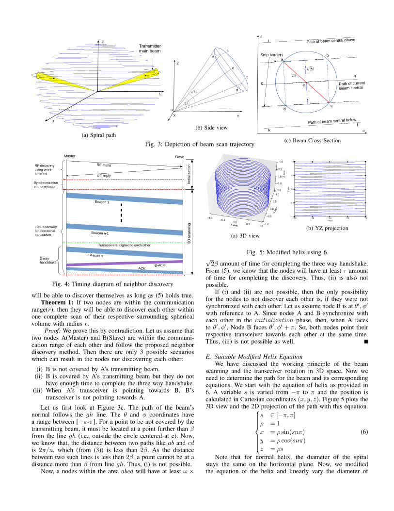
(a) Spiral path(b) Side view
(c) Beam Cross SectionFig. 3: Depiction of beam scan trajectory
Fig. 4: Timing diagram of neighbor discovery
will be able to discover themselves as long as (5) holds true.Theorem 1: If two nodes are within the communication
range(r), then they will be able to discover each other withinone complete scan of their respective surrounding sphericalvolume with radius r.
Proof: We prove this by contradiction. Let us assume thattwo nodes A(Master) and B(Slave) are within the communi-cation range of each other and follow the proposed neighbordiscovery method. Then there are only 3 possible scenarioswhich can result in the nodes not discovering each other:
(i) B is not covered by A’s transmitting beam.(ii) B is covered by A’s transmitting beam but they do not
have enough time to complete the three way handshake.(iii) When A’s transceiver is pointing towards B, B’s
transceiver is not pointing towards A.
Let us first look at Figure 3c. The path of the beam’snormal follows the gh line. The θ and φ coordinates havea range between [−π-π]. For a point to be not covered by thetransmitting beam, it must be located at a point further than βfrom the line gh (i.e., outside the circle centered at e). Now,we know that, the distance between two paths like ab and cdis 2π/n, which (from (3)) is less than 2β. As the distancebetween two such lines is less than 2β, a point cannot be at adistance more than β from line gh. Thus, (i) is not possible.
Now, a nodes within the area abcd will have at least ω ×
X axis
−1.0−0.5
0.00.5
1.0
Y ax
is
−1.0
−0.5
0.0
0.5
1.0
Z ax
is
−1.0
−0.5
0.0
0.5
1.0
(a) 3D view
−1.0 −0.5 0.0 0.5 1.0Y axis
−1.0
−0.5
0.0
0.5
1.0
Z ax
is
(b) YZ projection
Fig. 5: Modified helix using 6√2β amount of time for completing the three way handshake.
From (5), we know that the nodes will have at least τ amountof time for completing the discovery. Thus, (ii) is also notpossible.
If (i) and (ii) are not possible, then the only possibilityfor the nodes to not discover each other is, if they were notsynchronized with each other. Let us assume node B is at θ′, φ′with reference to A. Since nodes A and B synchronize witheach other in the initialization phase, then, when A facesto θ′, φ′, Node B faces θ′, φ′ + π. So, both nodes point theirrespective transceiver towards each other at the same time.Thus, (iii) is not possible as well.
E. Suitable Modified Helix EquationWe have discussed the working principle of the beam
scanning and the transceiver rotation in 3D space. Now weneed to determine the path for the beam and its correspondingequations. We start with the equation of helix as provided in6. A variable s is varied from −π to π and the position iscalculated in Cartesian coordinates (x, y, z). Figure 5 plots the3D view and the 2D projection of the path with this equation.
s ∈ [−π, π]ρ = 1
x = ρ sin(snπ)
y = ρ cos(snπ)
z = ρs
(6)
Note that for normal helix, the diameter of the spiralstays the same on the horizontal plane. Now, we modifiedthe equation of the helix and linearly vary the diameter of

X axis
−1.0−0.5
0.00.5
1.0
Y ax
is
−1.0
−0.5
0.0
0.5
1.0
Z ax
is
−1.0
−0.5
0.0
0.5
1.0
(a) 3D view
−1.0 −0.5 0.0 0.5 1.0Y axis
−1.0
−0.5
0.0
0.5
1.0
Z ax
is
(b) YZ projection
Fig. 6: Modified helix using 7
X axis
−1.0−0.5
0.00.5
1.0
Y ax
is
−1.0
−0.5
0.0
0.5
1.0
Z ax
is
−1.0
−0.5
0.0
0.5
1.0
(a) 3D view
−1.0 −0.5 0.0 0.5 1.0Y axis
−1.0
−0.5
0.0
0.5
1.0
Z ax
is
(b) YZ projection
Fig. 7: Modified helix using 8
the helix on the horizontal plane. In this case, the diameter ofthe spiral is 1 at the equator and 0 at the two poles. Thecorresponding position can be calculated as in 7. Figure 6illustrates the trajectory in 3D and 2D projections.
s ∈ [−1, 1]ρ = 1− |s|x = ρ sin(snπ)
y = ρ cos(snπ)
z = s
(7)
The modified helix presented in 7 does not satisfy ourrequirement of having same distance for 2 lines. So, wemodified the equations and try to vary the the movement inz axis to be varying with sin(s/2) instead of linearly varyingwith s. The equations are given in 8 and the correspondingtrajectories are presented in Figure 7.
s ∈ [−1, 1]ρ = 1− |s|x = ρ sin(snπ)
y = ρ cos(snπ)
z = sin(sπ/2)
(8)
The distance between two lines are now very similar.However, a particle moving along this line is not maintainingthe same distance from the center. So, we further modifiedthe equations as presented in (9). Here the width of the spiralvaries also in z axis as a cos function of s. Figure 8 illustratesthe trajectory in 3D and 2D projection. We have verified thatthe distance of a particle following this trajectory, from thecenter is the same for all values of s. If we vary s from −πto π, the beam scans the whole sphere.
X axis
−1.0−0.5
0.00.5
1.0
Y ax
is
−1.0
−0.5
0.0
0.5
1.0
Z ax
is
−1.0
−0.5
0.0
0.5
1.0
(a) 3D view
−1.0 −0.5 0.0 0.5 1.0Y axis
−1.0
−0.5
0.0
0.5
1.0
Z ax
is
(b) YZ projection
Fig. 8: Modified helix using 9
Time Spent(s)0 20 40 60
CD
F of
Dis
cove
ry0
0.2
0.4
0.6
0.8
1β = 3o
β = 5oβ = 7.5o
β = 12o
Time Spent(s)0 20 40 60
Pro
babi
lity
of D
isco
very
0
0.05
0.1
0.15
0.2
Fig. 9: CDF and probability of discovery for ω = 30 rpm
s ∈ [−π, π]ρ = cos(s/2)
x = ρ sin(ns)
y = ρ cos(ns)
z = sin(s/2)
(9)
IV. SIMULATIONS AND RESULTSWe performed MATLAB simulations to analyze the ef-
fectiveness of the proposed neighbor discovery method. Weconsidered master node’s hovering position as the origin.We randomly chose the position of the slave node for eachsimulation run. We assumed the communication range (100m)to be same for all cases. Moreover, we considered differentdivergence angles (3o, 5o, 7.5o, 12o) and different angularspeeds (30rpm − 300rpm) for the transceivers (rpm standsfor rotations per minute).
Figure 9 shows the cumulative distribution function (CDF)and the probability of neighbor discovery for different diver-gence angles for angular speed ω = 30rpm. We can observefrom the CDF that, the discovery time reduces with increase inthe divergence angle. Thus, the probability of discovery alsoincreases as divergence angle is increased. It is clear from thefigure that, transceivers with divergence angle of 12o finds eachother faster than transceivers with divergence angle of 3o.
In figure 10, we show the CDF of the discovery timefor different divergence angles and angular speeds of thetransceivers. We can observe that, for a fixed divergenceangle, increasing the rotational/angular speed of the transceiverreduces the neighbor discovery time, thus, improves the perfor-mance of the proposed method. For example, when β = 12o,the discovery time is less for ω = 300rpm than that forω = 100rpm. We also observe that, for ω = 300rpm, discover
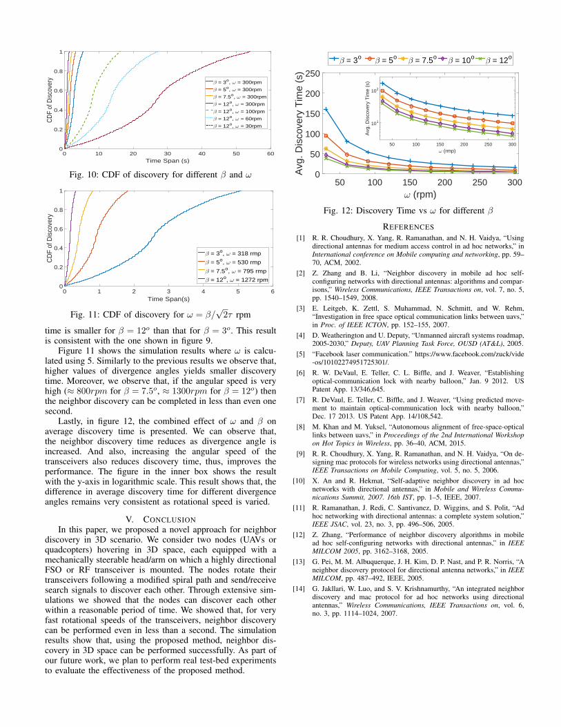
Time Span (s)0 10 20 30 40 50 60
CD
F of
Dis
cove
ry
0
0.2
0.4
0.6
0.8
1
β = 3o, ω = 300rpm
β = 5o, ω = 300rpm
β = 7.5o, ω = 300rpm
β = 12o, ω = 300rpm
β = 12o, ω = 100rpm
β = 12o, ω = 60rpm
β = 12o, ω = 30rpm
Fig. 10: CDF of discovery for different β and ω
Time Span(s)0 1 2 3 4 5 6
CD
F of
Dis
cove
ry
0
0.2
0.4
0.6
0.8
1
β = 3o, ω = 318 rmp
β = 5o, ω = 530 rmp
β = 7.5o, ω = 795 rmp
β = 12o, ω = 1272 rpm
Fig. 11: CDF of discovery for ω = β/√2τ rpm
time is smaller for β = 12o than that for β = 3o. This resultis consistent with the one shown in figure 9.
Figure 11 shows the simulation results where ω is calcu-lated using 5. Similarly to the previous results we observe that,higher values of divergence angles yields smaller discoverytime. Moreover, we observe that, if the angular speed is veryhigh (≈ 800rpm for β = 7.5o, ≈ 1300rpm for β = 12o) thenthe neighbor discovery can be completed in less than even onesecond.
Lastly, in figure 12, the combined effect of ω and β onaverage discovery time is presented. We can observe that,the neighbor discovery time reduces as divergence angle isincreased. And also, increasing the angular speed of thetransceivers also reduces discovery time, thus, improves theperformance. The figure in the inner box shows the resultwith the y-axis in logarithmic scale. This result shows that, thedifference in average discovery time for different divergenceangles remains very consistent as rotational speed is varied.
V. CONCLUSIONIn this paper, we proposed a novel approach for neighbor
discovery in 3D scenario. We consider two nodes (UAVs orquadcopters) hovering in 3D space, each equipped with amechanically steerable head/arm on which a highly directionalFSO or RF transceiver is mounted. The nodes rotate theirtransceivers following a modified spiral path and send/receivesearch signals to discover each other. Through extensive sim-ulations we showed that the nodes can discover each otherwithin a reasonable period of time. We showed that, for veryfast rotational speeds of the transceivers, neighbor discoverycan be performed even in less than a second. The simulationresults show that, using the proposed method, neighbor dis-covery in 3D space can be performed successfully. As part ofour future work, we plan to perform real test-bed experimentsto evaluate the effectiveness of the proposed method.
ω (rpm)50 100 150 200 250 300
Avg
. Dis
cove
ry T
ime
(s)
0
50
100
150
200
250
β = 3o β = 5oβ = 7.5o
β = 10oβ = 12o
ω (rmp)50 100 150 200 250 300
Avg
. Dis
cove
ry T
ime
(s)
101
102
Fig. 12: Discovery Time vs ω for different β
REFERENCES[1] R. R. Choudhury, X. Yang, R. Ramanathan, and N. H. Vaidya, “Using
directional antennas for medium access control in ad hoc networks,” inInternational conference on Mobile computing and networking, pp. 59–70, ACM, 2002.
[2] Z. Zhang and B. Li, “Neighbor discovery in mobile ad hoc self-configuring networks with directional antennas: algorithms and compar-isons,” Wireless Communications, IEEE Transactions on, vol. 7, no. 5,pp. 1540–1549, 2008.
[3] E. Leitgeb, K. Zettl, S. Muhammad, N. Schmitt, and W. Rehm,“Investigation in free space optical communication links between uavs,”in Proc. of IEEE ICTON, pp. 152–155, 2007.
[4] D. Weatherington and U. Deputy, “Unmanned aircraft systems roadmap,2005-2030,” Deputy, UAV Planning Task Force, OUSD (AT&L), 2005.
[5] “Facebook laser communication.” https://www.facebook.com/zuck/vide-os/10102274951725301/.
[6] R. W. DeVaul, E. Teller, C. L. Biffle, and J. Weaver, “Establishingoptical-communication lock with nearby balloon,” Jan. 9 2012. USPatent App. 13/346,645.
[7] R. DeVaul, E. Teller, C. Biffle, and J. Weaver, “Using predicted move-ment to maintain optical-communication lock with nearby balloon,”Dec. 17 2013. US Patent App. 14/108,542.
[8] M. Khan and M. Yuksel, “Autonomous alignment of free-space-opticallinks between uavs,” in Proceedings of the 2nd International Workshopon Hot Topics in Wireless, pp. 36–40, ACM, 2015.
[9] R. R. Choudhury, X. Yang, R. Ramanathan, and N. H. Vaidya, “On de-signing mac protocols for wireless networks using directional antennas,”IEEE Transactions on Mobile Computing, vol. 5, no. 5, 2006.
[10] X. An and R. Hekmat, “Self-adaptive neighbor discovery in ad hocnetworks with directional antennas,” in Mobile and Wireless Commu-nications Summit, 2007. 16th IST, pp. 1–5, IEEE, 2007.
[11] R. Ramanathan, J. Redi, C. Santivanez, D. Wiggins, and S. Polit, “Adhoc networking with directional antennas: a complete system solution,”IEEE JSAC, vol. 23, no. 3, pp. 496–506, 2005.
[12] Z. Zhang, “Performance of neighbor discovery algorithms in mobilead hoc self-configuring networks with directional antennas,” in IEEEMILCOM 2005, pp. 3162–3168, 2005.
[13] G. Pei, M. M. Albuquerque, J. H. Kim, D. P. Nast, and P. R. Norris, “Aneighbor discovery protocol for directional antenna networks,” in IEEEMILCOM, pp. 487–492, IEEE, 2005.
[14] G. Jakllari, W. Luo, and S. V. Krishnamurthy, “An integrated neighbordiscovery and mac protocol for ad hoc networks using directionalantennas,” Wireless Communications, IEEE Transactions on, vol. 6,no. 3, pp. 1114–1024, 2007.