Embed Size (px)
Citation preview

The Solar Water Pumping Company
LORENTZ CONNECTEDOperating Manual and User Guide.
2
1 Introduction . . . . . . . . . . . . . . . . . . . . . . . . . . . . . . . . . . . . . . . . . . . . . 3
2 Access and user rights . . . . . . . . . . . . . . . . . . . . . . . . . . . . . . . . . . . . . . . . 4
2.1 General access to pump systems . . . . . . . . . . . . . . . . . . . . . . . . . . . . . . . . . . . . . . . . 4
2.2 DataModule licenses . . . . . . . . . . . . . . . . . . . . . . . . . . . . . . . . . . . . . . . . . . . . . . 4
2.3 User level access rights . . . . . . . . . . . . . . . . . . . . . . . . . . . . . . . . . . . . . . . . . . . . . 4
2.4 Access for customers . . . . . . . . . . . . . . . . . . . . . . . . . . . . . . . . . . . . . . . . . . . . . . 4
3 PumpScanner . . . . . . . . . . . . . . . . . . . . . . . . . . . . . . . . . . . . . . . . . . . . . 5
3.1 Pre-requisites and planning . . . . . . . . . . . . . . . . . . . . . . . . . . . . . . . . . . . . . . . . . . . 6
3.2 PumpScanner setup . . . . . . . . . . . . . . . . . . . . . . . . . . . . . . . . . . . . . . . . . . . . . . . 6
3.2.1 Smartphone requirements . . . . . . . . . . . . . . . . . . . . . . . . . . . . . . . . . . . . . . . 6
3.2.2 Download and install of the PumpScanner App . . . . . . . . . . . . . . . . . . . . . . . . . . . . 7
3.2.3 Synchronize the clock on first start . . . . . . . . . . . . . . . . . . . . . . . . . . . . . . . . . . 8
3.2.4 Updating the PumpScanner App . . . . . . . . . . . . . . . . . . . . . . . . . . . . . . . . . . . . 8
3.3 Using PumpScanner . . . . . . . . . . . . . . . . . . . . . . . . . . . . . . . . . . . . . . . . . . . . . . . 9
3.3.1 Settings . . . . . . . . . . . . . . . . . . . . . . . . . . . . . . . . . . . . . . . . . . . . . . 10
3.3.2 PS and first generation PSk2 Pumps . . . . . . . . . . . . . . . . . . . . . . . . . . . . . . . . . 11
3.3.3 PSk2 pumps with SmartSolution support . . . . . . . . . . . . . . . . . . . . . . . . . . . . . . 19
3.3.4 Communicators . . . . . . . . . . . . . . . . . . . . . . . . . . . . . . . . . . . . . . . . . . . 33
3.3.5 Sites . . . . . . . . . . . . . . . . . . . . . . . . . . . . . . . . . . . . . . . . . . . . . . 35
3.4 Troubleshooting . . . . . . . . . . . . . . . . . . . . . . . . . . . . . . . . . . . . . . . . . . . . . . . 39
3.4.1 PumpScanner . . . . . . . . . . . . . . . . . . . . . . . . . . . . . . . . . . . . . . . . . . . . 39
3.4.2 Bluetooth connection . . . . . . . . . . . . . . . . . . . . . . . . . . . . . . . . . . . . . . . . 39
4 PS Communicator & pumpMANAGER . . . . . . . . . . . . . . . . . . . . . . . . . . . . . . . .40
4.1 PS Communicator . . . . . . . . . . . . . . . . . . . . . . . . . . . . . . . . . . . . . . . . . . . . . . . 41
4.2 pumpMANAGER . . . . . . . . . . . . . . . . . . . . . . . . . . . . . . . . . . . . . . . . . . . . . . . 41
Contents
2 Introduction 3
1 Introduction
LORENTZ CONNECTED products open up new opportuni-
ties to improve customer service and for new commercial
models.
Most LORENTZ solar water pumping systems are equipped
with a DataModule. This is an integral data logger and
remote control device for our range of solar water pumps.
The DataModule, combined with the LORENTZ PumpScan-
ner App for Android™ and LORENTZ pumpMANAGER open
new opportunities in drinking water supply for people and
livestock, irrigation and swimming pool applications. The PS
DataModule collects performance data from the pump sys-
tem and stores it for periodic collection. It uses Bluetooth®
to communicate with the LORENTZ PumpScanner App for
Android and – for remote monitoring – with the LORENTZ
PS Communicator and pumpMANAGER, allowing secure
data collection without physical connections.
New LORENTZ PSk2 systems with SmartSolution support
have an embedded DataModule with advanced pump
system control options. Pre-requisites and rights manage-
ment for these systems are the same as for other LORENTZ
systems but additional pump control settings are available.
For PumpScanner setup of PS and first generation PSk2
pumps please refer to 3.3.2 „PS and first generation PSk2
Pumps“ on page 11.
For PumpScanner setup of PSk2 pump systems with Smart-
Solution support please refer to 3.3.3 „PSk2 pumps with
SmartSolution support“ on page 19.
4 Access and user rights
2 .3 User level access rights
The available setup and control options in PumpScanner and
pumpMANAGER depend on individual user rights. Some
functions are limited to technical users only. Refer to Table 1
„User rights“ on page 4 for an overview.
The setting can be changed by Business Managers in part-
nerNET in Partner Program >> User Management by editing
the individual user.
2 .4 Access for customers
To give customers access to PumpScanner or pumpMAN-
AGER they must be registered on partnerNET in Support
>> Customers. Create a “new customer”, then edit it to
link it to a specific Site by using the “assign to Site” button
and invite individual users to this customer through their
email address. An invitation will be send to each of them
where they can then login to customerNET and download
PumpScanner.
Edit the invited users in partnerNET under Support >>
Customer to change the rights setting from “normal” to
“technical” user if required.
2 Access and user rights
2 .1 General access to pump systems
General access to CONNECTED products is managed
through “Sites” under the “Support” tab on partnerNET. A
pump system must be registered on Sites in order to be able
to access it through PumpScanner or pumpMANAGER.
For PumpScanner, after registering the system on partner-
NET Sites then the “License list” in PumpScanner settings
must be updated.
For pumpMANAGER, after registering the system and
setting up the hardware “pumpMANAGER credits” must
be obtained in partnerNET and the service must be started
within partnerNET >> Support >> Sites >> System.
2 .2 DataModule licenses
Access to unlicensed DataModules is restricted to DataMod-
ule setup. The DataModule can be licensed on partnerNET
Sites. Controllers shipped after March 2015 have the license
included.
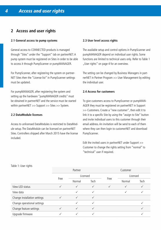
Table 1: User rightsPartner Customer
FreeLicensed
FreeLicensed
Normal Tech Normal Tech
View LED status P P P P P P
View data P P P P
Change installation settings P P P
Change operational settings P P P
Change feature settings P P P P
Upgrade firmware P P P P
4 Access and user rights PumpScanner 5
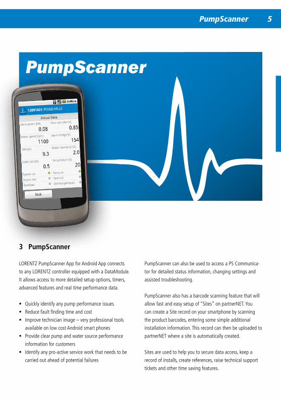
3 PumpScanner
LORENTZ PumpScanner App for Android App connects
to any LORENTZ controller equipped with a DataModule.
It allows access to more detailed setup options, timers,
advanced features and real time performance data.
� Quickly identify any pump performance issues
� Reduce fault finding time and cost
� Improve technician image – very professional tools
available on low cost Android smart phones
� Provide clear pump and water source performance
information for customers
� Identify any pro-active service work that needs to be
carried out ahead of potential failures
PumpScanner
PumpScanner can also be used to access a PS Communica-
tor for detailed status information, changing settings and
assisted troubleshooting.
PumpScanner also has a barcode scanning feature that will
allow fast and easy setup of “Sites” on partnerNET. You
can create a Site record on your smartphone by scanning
the product barcodes, entering some simple additional
installation information. This record can then be uploaded to
partnerNET where a site is automatically created.
Sites are used to help you to secure data access, keep a
record of installs, create references, raise technical support
tickets and other time saving features.
6 PumpScanner
3 .1 Pre-requisites and planning
To setup the features and functions of the PumpScanner
App and PS DataModule functionality you will need the
following:
� A PS Controller with either a PS DataModule installed
(PS, PSk2) or with an embedded DataModule (PSk2
with SmartSolution support)
� A registration of the pump system components on Sites
in the LORENTZ partnerNET
� An Android smartphone or tablet with running Android
2.3.3 or above with Bluetooth
� A LORENTZ partnerNET account to access your Pump-
Scanner license ID
� An internet connection to download PumpScanner
software and to update your PumpScanner license list
Before going to the work site to configure the PS DataMod-
ule it is recommended to set up a Site on partnerNET, access
your PumpScanner license ID, download PumpScanner and
update the license list in PumpScanner. The PS DataModule
cannot be accessed without setting up a Site on partnerNET
and updating the license list within PumpScanner, this
process is effectively your access key.
PumpScanner has a Site creation and upload feature, see
3.3.5 „Sites“ on page 35.
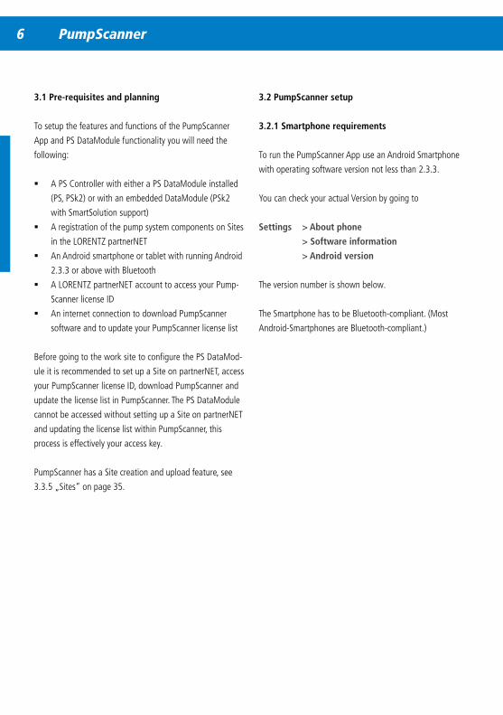
3 .2 PumpScanner setup
3 .2 .1 Smartphone requirements
To run the PumpScanner App use an Android Smartphone
with operating software version not less than 2.3.3.
You can check your actual Version by going to
Settings > About phone
> Software information
> Android version
The version number is shown below.
The Smartphone has to be Bluetooth-compliant. (Most
Android-Smartphones are Bluetooth-compliant.)
6 PumpScanner PumpScanner 7
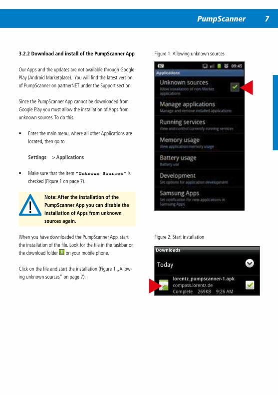
3 .2 .2 Download and install of the PumpScanner App
Our Apps and the updates are not available through Google
Play (Android Marketplace). You will find the latest version
of PumpScanner on partnerNET under the Support section.
Since the PumpScanner App cannot be downloaded from
Google Play you must allow the installation of Apps from
unknown sources. To do this
� Enter the main menu, where all other Applications are
located, then go to
Settings > Applications
� Make sure that the item “Unknown Sources” is
checked (Figure 1 on page 7).
Note: After the installation of the
PumpScanner App you can disable the
installation of Apps from unknown
sources again .
When you have downloaded the PumpScanner App, start
the installation of the file. Look for the file in the taskbar or
the download folder on your mobile phone.
Click on the file and start the installation (Figure 1 „Allow-
ing unknown sources“ on page 7).
Figure 1: Allowing unknown sources
Figure 2: Start installation
8 PumpScanner
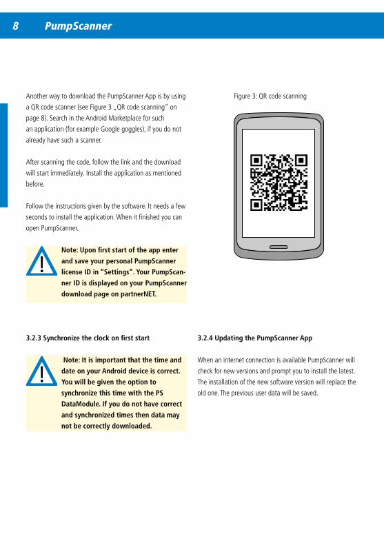
Another way to download the PumpScanner App is by using
a QR code scanner (see Figure 3 „QR code scanning“ on
page 8). Search in the Android Marketplace for such
an application (for example Google goggles), if you do not
already have such a scanner.
After scanning the code, follow the link and the download
will start immediately. Install the application as mentioned
before.
Follow the instructions given by the software. It needs a few
seconds to install the application. When it finished you can
open PumpScanner.
Note: Upon first start of the app enter
and save your personal PumpScanner
license ID in “Settings” . Your PumpScan-
ner ID is displayed on your PumpScanner
download page on partnerNET .
3 .2 .3 Synchronize the clock on first start
Note: It is important that the time and
date on your Android device is correct .
You will be given the option to
synchronize this time with the PS
DataModule . If you do not have correct
and synchronized times then data may
not be correctly downloaded .
3 .2 .4 Updating the PumpScanner App
When an internet connection is available PumpScanner will
check for new versions and prompt you to install the latest.
The installation of the new software version will replace the
old one. The previous user data will be saved.
Figure 3: QR code scanning
8 PumpScanner PumpScanner 9
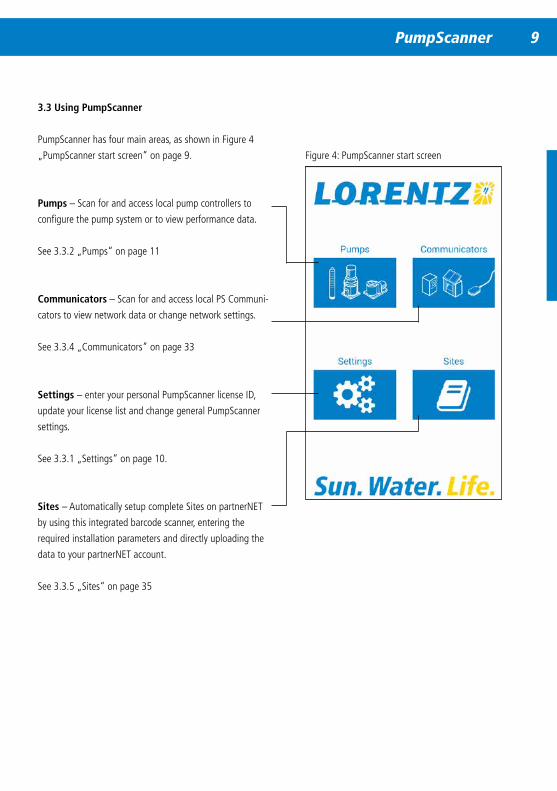
3 .3 Using PumpScanner
PumpScanner has four main areas, as shown in Figure 4
„PumpScanner start screen“ on page 9.
Pumps – Scan for and access local pump controllers to
configure the pump system or to view performance data.
See 3.3.2 „Pumps“ on page 11
Communicators – Scan for and access local PS Communi-
cators to view network data or change network settings.
See 3.3.4 „Communicators“ on page 33
Settings – enter your personal PumpScanner license ID,
update your license list and change general PumpScanner
settings.
See 3.3.1 „Settings“ on page 10.
Sites – Automatically setup complete Sites on partnerNET
by using this integrated barcode scanner, entering the
required installation parameters and directly uploading the
data to your partnerNET account.
See 3.3.5 „Sites“ on page 35
Figure 4: PumpScanner start screen
10 PumpScanner
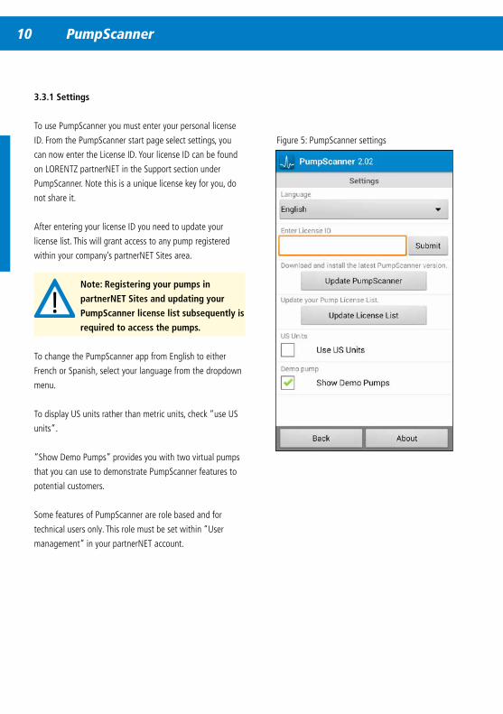
3 .3 .1 Settings
To use PumpScanner you must enter your personal license
ID. From the PumpScanner start page select settings, you
can now enter the License ID. Your license ID can be found
on LORENTZ partnerNET in the Support section under
PumpScanner. Note this is a unique license key for you, do
not share it.
After entering your license ID you need to update your
license list. This will grant access to any pump registered
within your company’s partnerNET Sites area.
Note: Registering your pumps in
partnerNET Sites and updating your
PumpScanner license list subsequently is
required to access the pumps .
To change the PumpScanner app from English to either
French or Spanish, select your language from the dropdown
menu.
To display US units rather than metric units, check “use US
units”.
“Show Demo Pumps” provides you with two virtual pumps
that you can use to demonstrate PumpScanner features to
potential customers.
Some features of PumpScanner are role based and for
technical users only. This role must be set within “User
management” in your partnerNET account.
Figure 5: PumpScanner settings
10 PumpScanner PumpScanner 11
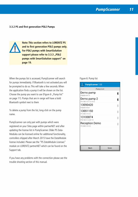
3 .3 .2 PS and first generation PSk2 Pumps
Note: This section refers to LORENTZ PS
and to first generation PSk2 pumps only .
For PSk2 pumps with SmartSolution
support please refer to 3 .3 .3 „PSk2
pumps with SmartSolution support“ on
page 19 .
When the pumps list is accessed, PumpScanner will search
for pumps immediately. If Bluetooth is not activated you will
be prompted to do so. This will take a few seconds. When
the application finds a pump it will be shown on the list.
Choose the pump you want to use (Figure 6 „Pump list“
on page 11). Pumps that are in range will have a bold
Bluetooth symbol next to them
To delete a pump from the list, long-click on the pump
name.
PumpScanner can only pair with pumps which were
registered on your Sites page within partnerNET and after
updating the license list in PumpScanner. Older PS Data-
Modules can be licensed online for additional functionality,
controllers shipped after March 2015 have the DataModule
license included. Please see the “PS DataModule Licenses”
module on LORENTZ partnerNET which can be found on the
Support tab.
If you have any problems with the connection please see the
trouble shooting section of this manual.
Figure 6: Pump list

12 PumpScanner
Figure 7: Pump data and settings
3 .3 .2 .1 Pumps – System Overview
Tap a pump to access detailed settings and performance
data for it. This is only possible while in Bluetooth range.
Once you are connected via Bluetooth to a PS DataModule
you should first make sure that your Pump profile is correct
and saved (Figure 8 „Installation settings“ on page 13).
Note: Your actual and historic data will
not be correct if the DataModule is not
configured correctly .
12 PumpScanner PumpScanner 13
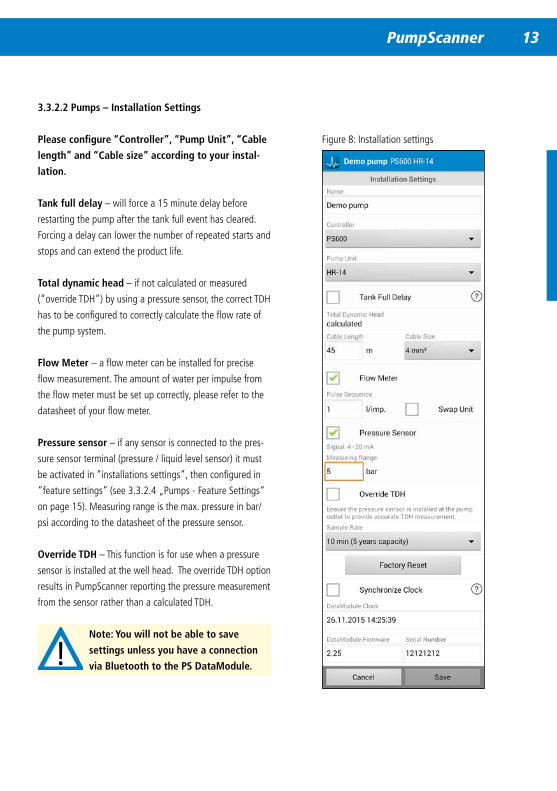
3 .3 .2 .2 Pumps – Installation Settings
Please configure “Controller”, “Pump Unit”, “Cable
length” and “Cable size” according to your instal-
lation .
Tank full delay – will force a 15 minute delay before
restarting the pump after the tank full event has cleared.
Forcing a delay can lower the number of repeated starts and
stops and can extend the product life.
Total dynamic head – if not calculated or measured
(“override TDH”) by using a pressure sensor, the correct TDH
has to be configured to correctly calculate the flow rate of
the pump system.
Flow Meter – a flow meter can be installed for precise
flow measurement. The amount of water per impulse from
the flow meter must be set up correctly, please refer to the
datasheet of your flow meter.
Pressure sensor – if any sensor is connected to the pres-
sure sensor terminal (pressure / liquid level sensor) it must
be activated in “installations settings”, then configured in
“feature settings” (see 3.3.2.4 „Pumps - Feature Settings“
on page 15). Measuring range is the max. pressure in bar/
psi according to the datasheet of the pressure sensor.
Override TDH – This function is for use when a pressure
sensor is installed at the well head. The override TDH option
results in PumpScanner reporting the pressure measurement
from the sensor rather than a calculated TDH.
Note: You will not be able to save
settings unless you have a connection
via Bluetooth to the PS DataModule .
Figure 8: Installation settings
14 PumpScanner
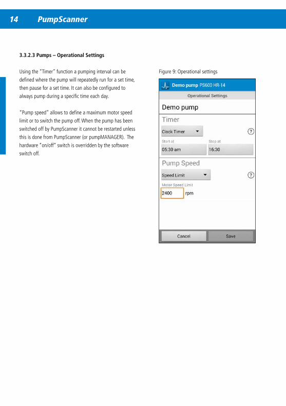
Figure 9: Operational settings
3 .3 .2 .3 Pumps – Operational Settings
Using the “Timer” function a pumping interval can be
defined where the pump will repeatedly run for a set time,
then pause for a set time. It can also be configured to
always pump during a specific time each day.
“Pump speed” allows to define a maximum motor speed
limit or to switch the pump off. When the pump has been
switched off by PumpScanner it cannot be restarted unless
this is done from PumpScanner (or pumpMANAGER). The
hardware “on/off” switch is overridden by the software
switch off.

14 PumpScanner PumpScanner 15
Figure 10: Feature settings
3 .3 .2 .4 Pumps – Feature Settings
To access some feature settings for a pump an appropri-
ate sensor must be registered with the pump system on
partnerNET Sites.
From the drop down menu in “feature settings” select the
function according to what is installed at the sensor input,
see Figure 10 on page 15.
Pressure measurement – requires a pressure sensor.
The pressure readings from the sensor will be recorded by
the DataModule. “Pressure sensor” must be enabled in
installations settings, see Figure 8 „Installation settings“ on
page 13.
TDH Measurement – the pressure measured at the pump
outlet will replace the calculated TDH value. “Pressure sen-
sor” and ““Override TDH” must be enabled in installation
settings, see Figure 8 „Installation settings“ on page 13.
Water level – with a LORENTZ liquid level sensor installed
the level of the fluid above the sensor can be measured.
An offset can be defined that will only affect the displayed
water level to account for installation specific details and/
or requirements, such as the installation depth of the sensor.
“Pressure sensor” must be enabled in installations settings,
see Figure 8 „Installation settings“ on page 13.
Pump control – Using a pressure or liquid level sensor,
the pump system can be configured to stop automatically
when the pressure/water level drops below a specific setting
(“Pump OFF below x bar/psi/meter/ft”) and to restart, when
the pressure rises above a specific setting (“Pump ON above
x bar/psi/meter/ft”) and vice versa. To switch between
modes, tap either “below” or “above”.
16 PumpScanner
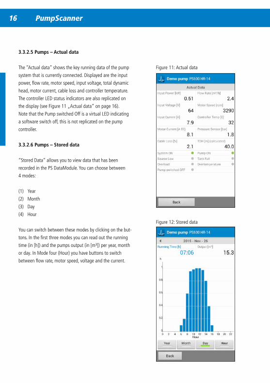
Figure 11: Actual data
3 .3 .2 .5 Pumps – Actual data
The “Actual data” shows the key running data of the pump
system that is currently connected. Displayed are the input
power, flow rate, motor speed, input voltage, total dynamic
head, motor current, cable loss and controller temperature.
The controller LED status indicators are also replicated on
the display (see Figure 11 „Actual data“ on page 16).
Note that the Pump switched Off is a virtual LED indicating
a software switch off, this is not replicated on the pump
controller.
3 .3 .2 .6 Pumps – Stored data
“Stored Data” allows you to view data that has been
recorded in the PS DataModule. You can choose between
4 modes:
(1) Year
(2) Month
(3) Day
(4) Hour
You can switch between these modes by clicking on the but-
tons. In the first three modes you can read out the running
time (in [h]) and the pumps output (in [m³]) per year, month
or day. In Mode four (Hour) you have buttons to switch
between flow rate, motor speed, voltage and the current.
Figure 12: Stored data
16 PumpScanner PumpScanner 17
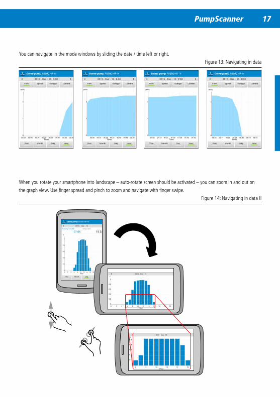
When you rotate your smartphone into landscape – auto-rotate screen should be activated – you can zoom in and out on
the graph view. Use finger spread and pinch to zoom and navigate with finger swipe.
You can navigate in the mode windows by sliding the date / time left or right.
Figure 13: Navigating in data
Figure 14: Navigating in data II
18 PumpScanner
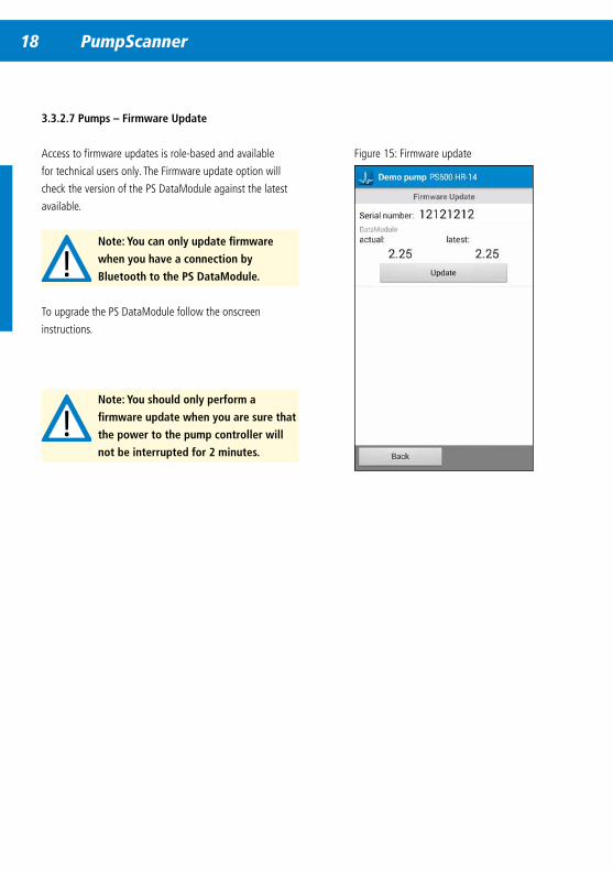
3 .3 .2 .7 Pumps – Firmware Update
Access to firmware updates is role-based and available
for technical users only. The Firmware update option will
check the version of the PS DataModule against the latest
available.
Note: You can only update firmware
when you have a connection by
Bluetooth to the PS DataModule .
To upgrade the PS DataModule follow the onscreen
instructions.
Figure 15: Firmware update
Note: You should only perform a
firmware update when you are sure that
the power to the pump controller will
not be interrupted for 2 minutes .
18 PumpScanner PumpScanner 19
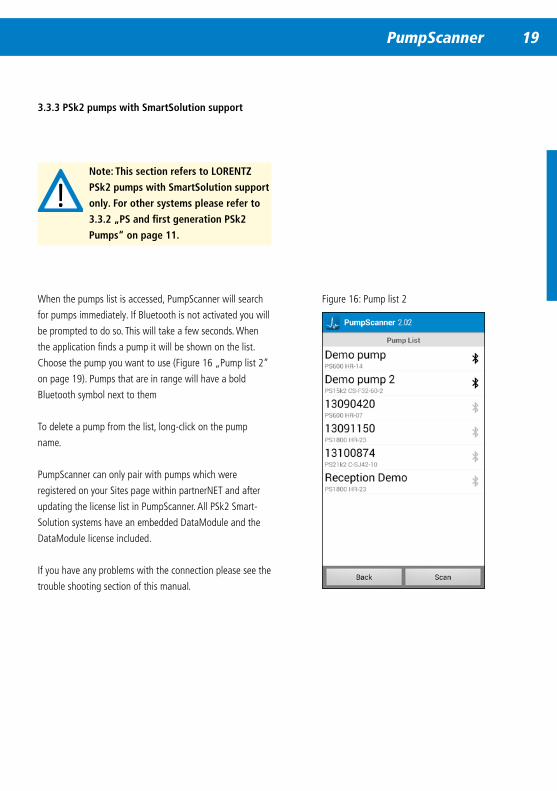
3 .3 .3 PSk2 pumps with SmartSolution support
Note: This section refers to LORENTZ
PSk2 pumps with SmartSolution support
only . For other systems please refer to
3 .3 .2 „PS and first generation PSk2
Pumps“ on page 11 .
When the pumps list is accessed, PumpScanner will search
for pumps immediately. If Bluetooth is not activated you will
be prompted to do so. This will take a few seconds. When
the application finds a pump it will be shown on the list.
Choose the pump you want to use (Figure 16 „Pump list 2“
on page 19). Pumps that are in range will have a bold
Bluetooth symbol next to them
To delete a pump from the list, long-click on the pump
name.
PumpScanner can only pair with pumps which were
registered on your Sites page within partnerNET and after
updating the license list in PumpScanner. All PSk2 Smart-
Solution systems have an embedded DataModule and the
DataModule license included.
If you have any problems with the connection please see the
trouble shooting section of this manual.
Figure 16: Pump list 2
20 PumpScanner
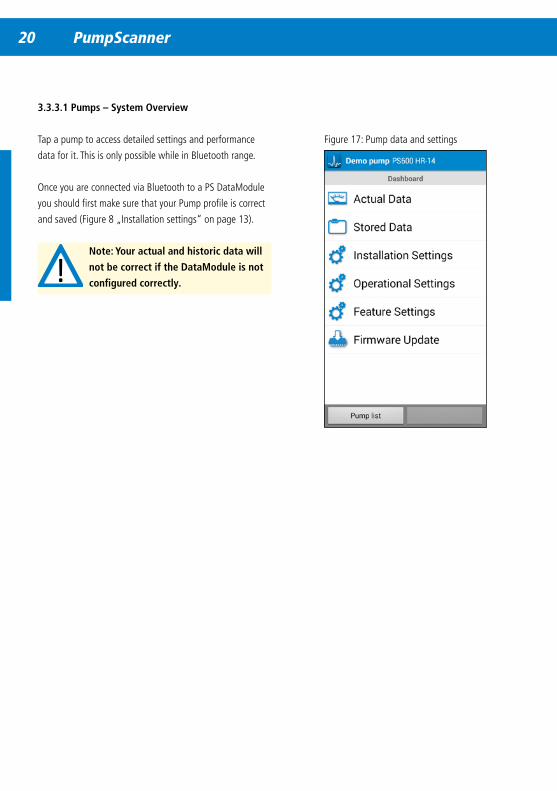
Figure 17: Pump data and settings
3 .3 .3 .1 Pumps – System Overview
Tap a pump to access detailed settings and performance
data for it. This is only possible while in Bluetooth range.
Once you are connected via Bluetooth to a PS DataModule
you should first make sure that your Pump profile is correct
and saved (Figure 8 „Installation settings“ on page 13).
Note: Your actual and historic data will
not be correct if the DataModule is not
configured correctly .
20 PumpScanner PumpScanner 21
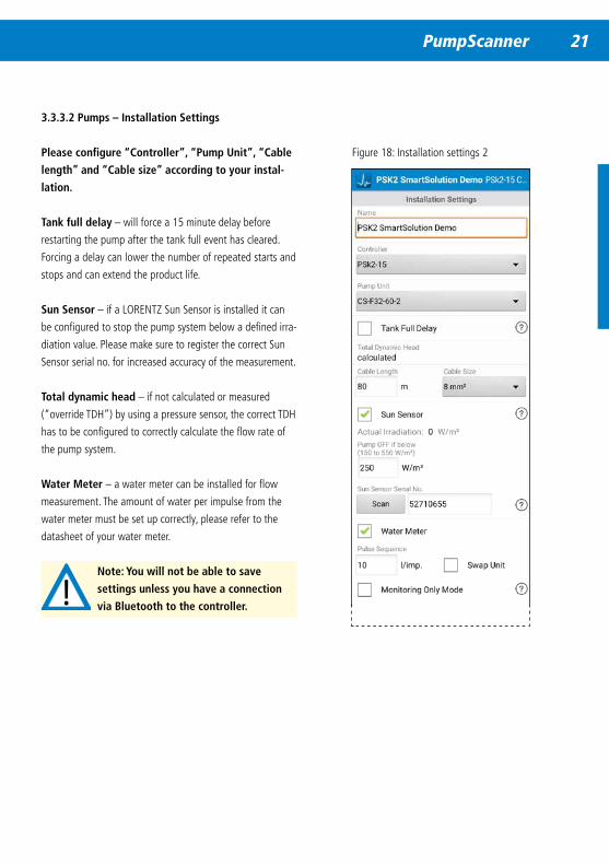
3 .3 .3 .2 Pumps – Installation Settings
Please configure “Controller”, “Pump Unit”, “Cable
length” and “Cable size” according to your instal-
lation .
Tank full delay – will force a 15 minute delay before
restarting the pump after the tank full event has cleared.
Forcing a delay can lower the number of repeated starts and
stops and can extend the product life.
Sun Sensor – if a LORENTZ Sun Sensor is installed it can
be configured to stop the pump system below a defined irra-
diation value. Please make sure to register the correct Sun
Sensor serial no. for increased accuracy of the measurement.
Total dynamic head – if not calculated or measured
(“override TDH”) by using a pressure sensor, the correct TDH
has to be configured to correctly calculate the flow rate of
the pump system.
Water Meter – a water meter can be installed for flow
measurement. The amount of water per impulse from the
water meter must be set up correctly, please refer to the
datasheet of your water meter.
Note: You will not be able to save
settings unless you have a connection
via Bluetooth to the controller .
Figure 18: Installation settings 2
22 PumpScanner
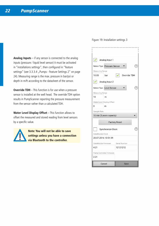
Analog Inputs – if any sensor is connected to the analog
inputs (pressure / liquid level sensor) it must be activated
in “installations settings”, then configured in “feature
settings” (see 3.3.3.4 „Pumps - Feature Settings 2“ on page
24). Measuring range is the max. pressure in bar/psi or
depth in m/ft according to the datasheet of the sensor.
Override TDH – This function is for use when a pressure
sensor is installed at the well head. The override TDH option
results in PumpScanner reporting the pressure measurement
from the sensor rather than a calculated TDH.
Water Level Display Offset – This function allows to
offset the measured and stored reading from level sensors
by a specific value.
Note: You will not be able to save
settings unless you have a connection
via Bluetooth to the controller .
Figure 19: Installation settings 3
22 PumpScanner PumpScanner 23
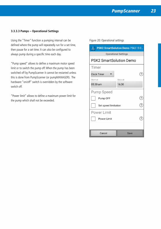
Figure 20: Operational settings
3 .3 .3 .3 Pumps – Operational Settings
Using the “Timer” function a pumping interval can be
defined where the pump will repeatedly run for a set time,
then pause for a set time. It can also be configured to
always pump during a specific time each day.
“Pump speed” allows to define a maximum motor speed
limit or to switch the pump off. When the pump has been
switched off by PumpScanner it cannot be restarted unless
this is done from PumpScanner (or pumpMANAGER). The
hardware “on/off” switch is overridden by the software
switch off.
“Power limit” allows to define a maximum power limit for
the pump which shall not be exceeded.
24 PumpScanner
Figure 21: Feature settings 2
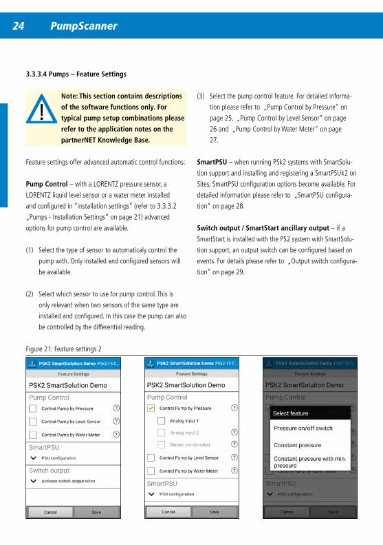
3 .3 .3 .4 Pumps – Feature Settings
Note: This section contains descriptions
of the software functions only . For
typical pump setup combinations please
refer to the application notes on the
partnerNET Knowledge Base .
Feature settings offer advanced automatic control functions:
Pump Control – with a LORENTZ pressure sensor, a
LORENTZ liquid level sensor or a water meter installed
and configured in “installation settings” (refer to 3.3.3.2
„Pumps - Installation Settings“ on page 21) advanced
options for pump control are available.
(1) Select the type of sensor to automaticaly control the
pump with. Only installed and configured sensors will
be available.
(2) Select which sensor to use for pump control. This is
only relevant when two sensors of the same type are
installed and configured. In this case the pump can also
be controlled by the differential reading.
(3) Select the pump control feature. For detailed informa-
tion please refer to „Pump Control by Pressure“ on
page 25, „Pump Control by Level Sensor“ on page
26 and „Pump Control by Water Meter“ on page
27.
SmartPSU – when running PSk2 systems with SmartSolu-
tion support and installing and registering a SmartPSUk2 on
Sites, SmartPSU configuration options become available. For
detailed information please refer to „SmartPSU configura-
tion“ on page 28.
Switch output / SmartStart ancillary output – if a
SmartStart is installed with the PS2 system with SmartSolu-
tion support, an output switch can be configured based on
events. For details please refer to „Output switch configura-
tion“ on page 29.
24 PumpScanner PumpScanner 25
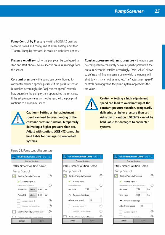
Figure 22: Pump control by pressure
Pump Control by Pressure – with a LORENTZ pressure
sensor installed and configured at either analog input then
“Control Pump by Pressure” is available with three options:
Pressure on/off switch – the pump can be configured to
stop and start above / below specific pressure readings from
the sensor.
Constant pressure – the pump can be configured to
constantly deliver a specific pressure if the pressure sensor
is installed accordingly. The “adjustment speed” controls
how aggresive the pump system approaches the set value.
If the set pressure value can not be reached the pump will
continue to run at max. speed.
Caution – Setting a high adjustment
speed can lead to overshooting of the
constant pressure function, temporarily
delivering a higher pressure than set .
Adjust with caution . LORENTZ cannot be
held liable for damages to connected
systems .
Constant pressure with min . pressure – the pump can
be configured to constantly deliver a specific pressure if the
pressure sensor is installed accordingly. “Min. value” allows
to define a minimum pressure below which the pump will
shut down if it can not be reached. The “adjustment speed”
controls how aggresive the pump system approaches the
set value.
Caution – Setting a high adjustment
speed can lead to overshooting of the
constant pressure function, temporarily
delivering a higher pressure than set .
Adjust with caution . LORENTZ cannot be
held liable for damages to connected
systems .
26 PumpScanner
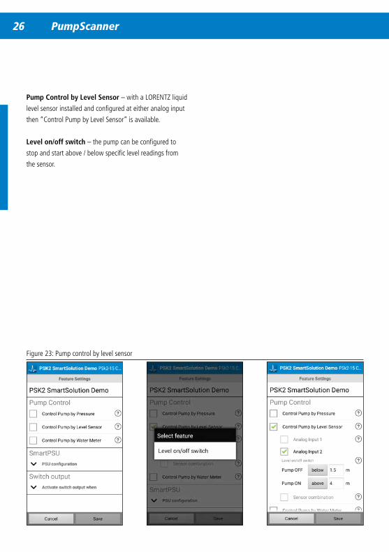
Figure 23: Pump control by level sensor
Pump Control by Level Sensor – with a LORENTZ liquid
level sensor installed and configured at either analog input
then “Control Pump by Level Sensor” is available.
Level on/off switch – the pump can be configured to
stop and start above / below specific level readings from
the sensor.
26 PumpScanner PumpScanner 27
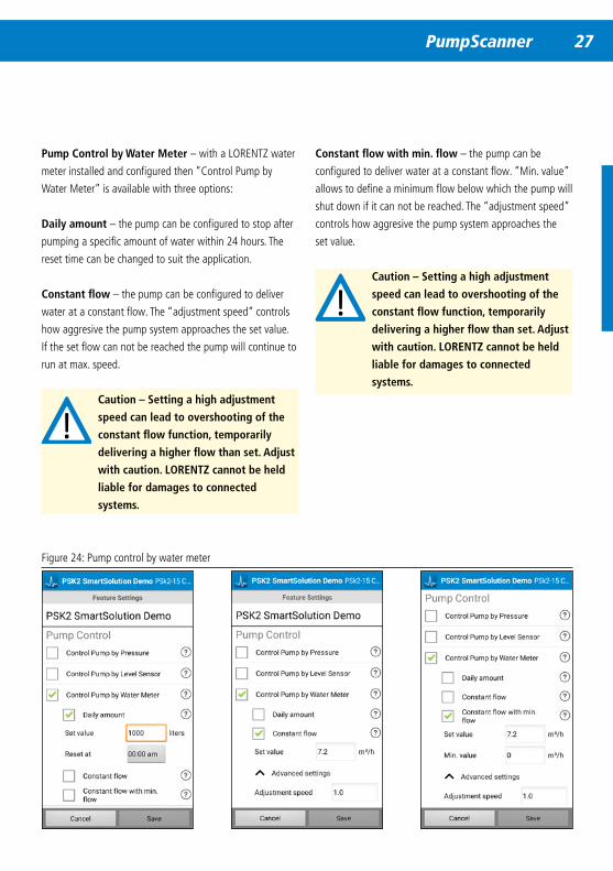
Figure 24: Pump control by water meter
Pump Control by Water Meter – with a LORENTZ water
meter installed and configured then “Control Pump by
Water Meter” is available with three options:
Daily amount – the pump can be configured to stop after
pumping a specific amount of water within 24 hours. The
reset time can be changed to suit the application.
Constant flow – the pump can be configured to deliver
water at a constant flow. The “adjustment speed” controls
how aggresive the pump system approaches the set value.
If the set flow can not be reached the pump will continue to
run at max. speed.
Caution – Setting a high adjustment
speed can lead to overshooting of the
constant flow function, temporarily
delivering a higher flow than set . Adjust
with caution . LORENTZ cannot be held
liable for damages to connected
systems .
Constant flow with min . flow – the pump can be
configured to deliver water at a constant flow. “Min. value”
allows to define a minimum flow below which the pump will
shut down if it can not be reached. The “adjustment speed”
controls how aggresive the pump system approaches the
set value.
Caution – Setting a high adjustment
speed can lead to overshooting of the
constant flow function, temporarily
delivering a higher flow than set . Adjust
with caution . LORENTZ cannot be held
liable for damages to connected
systems .
28 PumpScanner
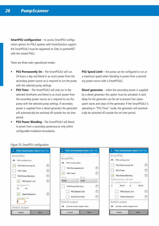
Figure 25: SmartPSU configuration
SmartPSU configuration – to access SmartPSU configu-
ration options for PSk2 systems with SmartSolution support
the SmartPSUk2 must be registered on Sites in partnerNET
with the related PSk2.
There are three main operational modes:
� PSU Permanently On – The SmartPSUk2 will run
24 hours a day and blend in as much power from the
secondary power source as is required to run the pump
with the selected pump settings.
� PSU Timer – The SmartPSUk2 will only run in the
selected timeframe and blend in as much power from
the secondary power source as is required to run the
pump with the selected pump settings. If secondary
power is supplied from a diesel generator the generator
will automatically be switched off outside the set time
period.
� PSU Power Blending – The SmartPSUk2 will blend
in power from a secondary powersource only within
configurable irradiation boundaries.
PSU Speed Limit – the pump can be configured to run at
a maximum speed when blending in power from a second-
ary power source with a SmartPSUk2.
Diesel generator – when the secondary power is supplied
by a diesel generator this option must be activated. A start
delay for the generator can be set to prevent fast subse-
quent starts and stops of the generator. If the SmartPSUk2 is
operating in “PSU Timer” mode, the generator will automat-
ically be switched off outside the set time period.
28 PumpScanner PumpScanner 29
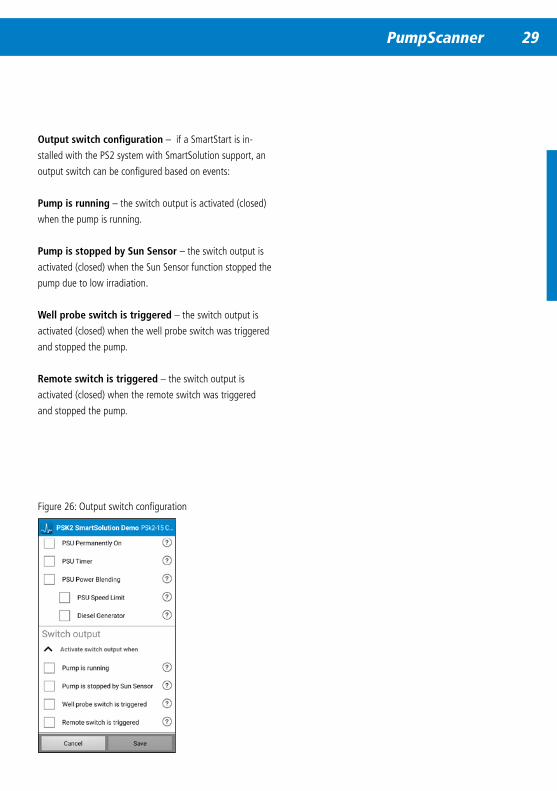
Figure 26: Output switch configuration
Output switch configuration – if a SmartStart is in-
stalled with the PS2 system with SmartSolution support, an
output switch can be configured based on events:
Pump is running – the switch output is activated (closed)
when the pump is running.
Pump is stopped by Sun Sensor – the switch output is
activated (closed) when the Sun Sensor function stopped the
pump due to low irradiation.
Well probe switch is triggered – the switch output is
activated (closed) when the well probe switch was triggered
and stopped the pump.
Remote switch is triggered – the switch output is
activated (closed) when the remote switch was triggered
and stopped the pump.
30 PumpScanner
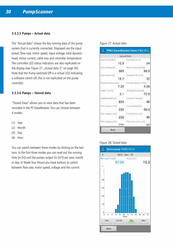
Figure 27: Actual data
3 .3 .3 .5 Pumps – Actual data
The “Actual data” shows the key running data of the pump
system that is currently connected. Displayed are the input
power, flow rate, motor speed, input voltage, total dynamic
head, motor current, cable loss and controller temperature.
The controller LED status indicators are also replicated on
the display (see Figure 27 „Actual data 3“ on page 30).
Note that the Pump switched Off is a virtual LED indicating
a software switch off, this is not replicated on the pump
controller.
3 .3 .3 .6 Pumps – Stored data
“Stored Data” allows you to view data that has been
recorded in the PS DataModule. You can choose between
4 modes:
(1) Year
(2) Month
(3) Day
(4) Hour
You can switch between these modes by clicking on the but-
tons. In the first three modes you can read out the running
time (in [h]) and the pumps output (in [m³]) per year, month
or day. In Mode four (Hour) you have buttons to switch
between flow rate, motor speed, voltage and the current.
Figure 28: Stored data

30 PumpScanner PumpScanner 31
When you rotate your smartphone into landscape – auto-rotate screen should be activated – you can zoom in and out on
the graph view. Use finger spread and pinch to zoom and navigate with finger swipe.
You can navigate in the mode windows by sliding the date / time left or right.
Figure 29: Navigating in data
Figure 30: Navigating in data II
32 PumpScanner
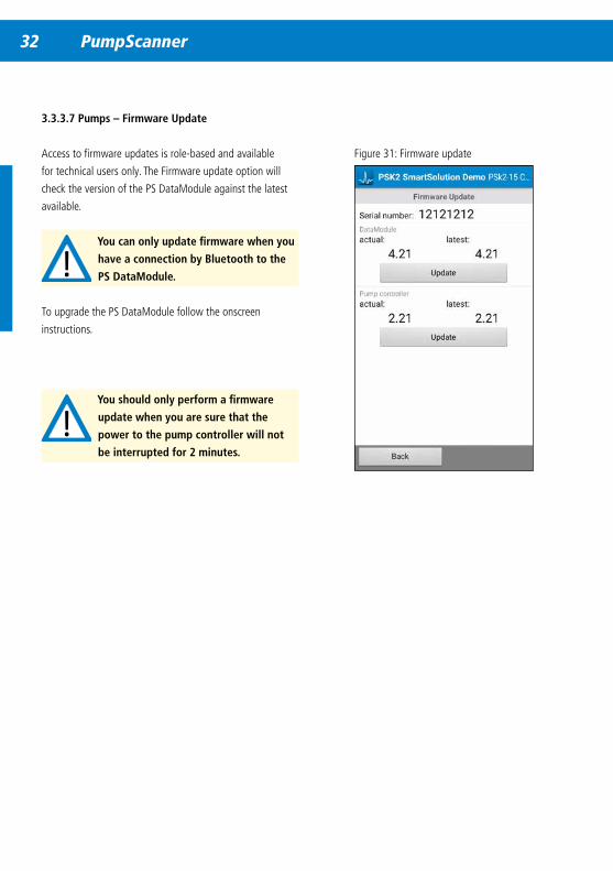
3 .3 .3 .7 Pumps – Firmware Update
Access to firmware updates is role-based and available
for technical users only. The Firmware update option will
check the version of the PS DataModule against the latest
available.
You can only update firmware when you
have a connection by Bluetooth to the
PS DataModule .
To upgrade the PS DataModule follow the onscreen
instructions.
Figure 31: Firmware update
You should only perform a firmware
update when you are sure that the
power to the pump controller will not
be interrupted for 2 minutes .
32 PumpScanner PumpScanner 33
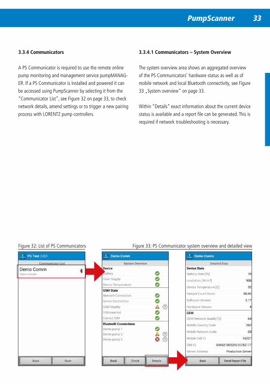
3 .3 .4 Communicators
A PS Communicator is required to use the remote online
pump monitoring and management service pumpMANAG-
ER. If a PS Communicator is installed and powered it can
be accessed using PumpScanner by selecting it from the
“Communicator List”, see Figure 32 on page 33, to check
network details, amend settings or to trigger a new pairing
process with LORENTZ pump controllers.
Figure 32: List of PS Communicators Figure 33: PS Communicator system overview and detailed view
3 .3 .4 .1 Communicators – System Overview
The system overview area shows an aggregated overview
of the PS Communicators’ hardware status as well as of
mobile network and local Bluetooth connectivity, see Figure
33 „System overview“ on page 33.
Within “Details” exact information about the current device
status is available and a report file can be generated. This is
required if network troubleshooting is necessary.
34 PumpScanner
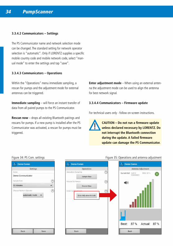
3 .3 .4 .2 Communicators – Settings
The PS Communicator name and network selection mode
can be changed. The standard setting for network operator
selection is “automatic”. Only if LORENTZ supplies a specific
mobile country code and mobile network code, select “man-
ual mode” to enter the settings and tap “save”.
3 .3 .4 .3 Communicators – Operations
Within the “Operations” menu immediate sampling, a
rescan for pumps and the adjustment mode for external
antennas can be triggered.
Immediate sampling – will force an instant transfer of
data from all paired pumps to the PS Communicator.
Rescan now – drops all existing Bluetooth pairings and
rescans for pumps. If a new pump is installed after the PS
Communicator was activated, a rescan for pumps must be
triggered.
Figure 34: PS Com. settings Figure 35: Operations and antenna adjustment
Enter adjustment mode – When using an external anten-
na the adjustment mode can be used to align the antenna
for best network signal.
3 .3 .4 .4 Communicators – Firmware update
For technical users only - follow on-screen instructions.
CAUTION – Do not run a firmware update
unless declared necessary by LORENTZ . Do
not interrupt the Bluetooth connection
during the update . A failed firmware
update can damage the PS Communicator .
34 PumpScanner PumpScanner 35
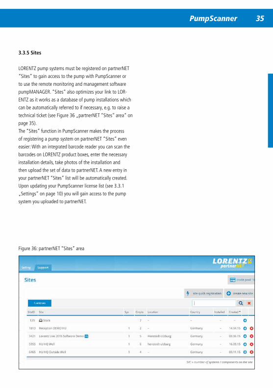
3 .3 .5 Sites
LORENTZ pump systems must be registered on partnerNET
“Sites” to gain access to the pump with PumpScanner or
to use the remote monitoring and management software
pumpMANAGER. “Sites” also optimizes your link to LOR-
ENTZ as it works as a database of pump installations which
can be automatically referred to if necessary, e.g. to raise a
technical ticket (see Figure 36 „partnerNET “Sites” area“ on
page 35).
The “Sites” function in PumpScanner makes the process
of registering a pump system on partnerNET “Sites” even
easier: With an integrated barcode reader you can scan the
barcodes on LORENTZ product boxes, enter the necessary
installation details, take photos of the installation and
then upload the set of data to partnerNET. A new entry in
your partnerNET “Sites” list will be automatically created.
Upon updating your PumpScanner license list (see 3.3.1
„Settings“ on page 10) you will gain access to the pump
system you uploaded to partnerNET.
Figure 36: partnerNET “Sites” area
36 PumpScanner
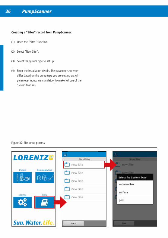
Creating a “Sites” record from PumpScanner:
(1) Open the “Sites” function.
(2) Select “New Site”.
(3) Select the system type to set up.
(4) Enter the installation details. The parameters to enter
differ based on the pump type you are setting up. All
parameter inputs are mandatory to make full use of the
“Sites” features.
Figure 37: Site setup process
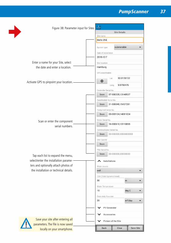
36 PumpScanner PumpScanner 37
Enter a name for your Site, select
the date and enter a location.
Activate GPS to pinpoint your location.
Scan or enter the component
serial numbers.
Tap each list to expand the menu,
select/enter the installation parame-
ters and optionally attach photos of
the installation or technical details.
Figure 38: Parameter input for Sites
Save your site after entering all
parameters. The file is now saved
locally on your smartphone.
38 PumpScanner
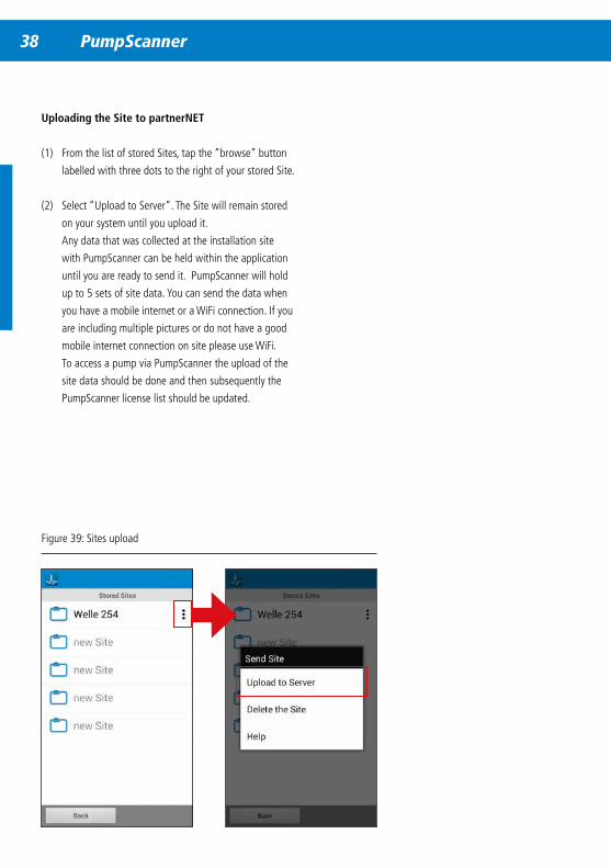
Figure 39: Sites upload
Uploading the Site to partnerNET
(1) From the list of stored Sites, tap the “browse” button
labelled with three dots to the right of your stored Site.
(2) Select “Upload to Server”. The Site will remain stored
on your system until you upload it.
Any data that was collected at the installation site
with PumpScanner can be held within the application
until you are ready to send it. PumpScanner will hold
up to 5 sets of site data. You can send the data when
you have a mobile internet or a WiFi connection. If you
are including multiple pictures or do not have a good
mobile internet connection on site please use WiFi.
To access a pump via PumpScanner the upload of the
site data should be done and then subsequently the
PumpScanner license list should be updated.
38 PumpScanner PumpScanner 39
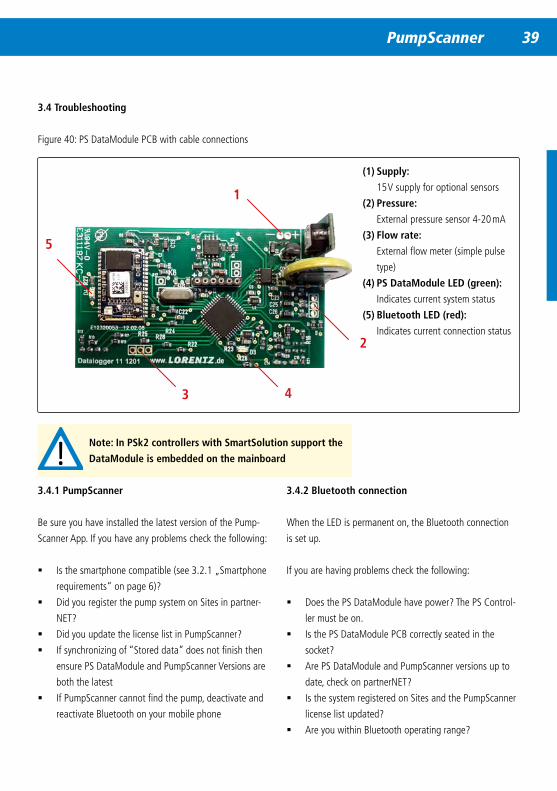
3 .4 Troubleshooting
3 .4 .1 PumpScanner
Be sure you have installed the latest version of the Pump-
Scanner App. If you have any problems check the following:
� Is the smartphone compatible (see 3.2.1 „Smartphone
requirements“ on page 6)?
� Did you register the pump system on Sites in partner-
NET?
� Did you update the license list in PumpScanner?
� If synchronizing of “Stored data” does not finish then
ensure PS DataModule and PumpScanner Versions are
both the latest
� If PumpScanner cannot find the pump, deactivate and
reactivate Bluetooth on your mobile phone
3 .4 .2 Bluetooth connection
When the LED is permanent on, the Bluetooth connection
is set up.
If you are having problems check the following:
� Does the PS DataModule have power? The PS Control-
ler must be on.
� Is the PS DataModule PCB correctly seated in the
socket?
� Are PS DataModule and PumpScanner versions up to
date, check on partnerNET?
� Is the system registered on Sites and the PumpScanner
license list updated?
� Are you within Bluetooth operating range?
(1) Supply:
15 V supply for optional sensors
(2) Pressure:
External pressure sensor 4-20 mA
(3) Flow rate:
External flow meter (simple pulse
type)
(4) PS DataModule LED (green):
Indicates current system status
(5) Bluetooth LED (red):
Indicates current connection status
1
2
43
5
Figure 40: PS DataModule PCB with cable connections
Note: In PSk2 controllers with SmartSolution support the
DataModule is embedded on the mainboard
40 PS Communicator & pumpMANAGER
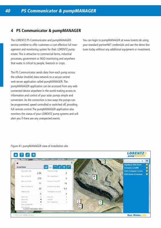
4 PS Communicator & pumpMANAGER
Figure 41: pumpMANAGER view of installation site
You can login to pumpMANAGER at www.lorentz.de using
your standard partnerNET credentials and see the demo fea-
tures today without any additional equipment or investment.
The LORENTZ PS Communicator and pumpMANAGER
service combine to offer customers a cost effective full man-
agement and monitoring system for their LORENTZ pump
estate. This is attractive to commercial farms, industrial
processes, government or NGO monitoring and anywhere
that water is critical to people, livestock or crops.
The PS Communicator sends data from each pump across
the cellular (mobile) data network to a secure central
web server application called pumpMANAGER. The
pumpMANAGER application can be accessed from any web
connected device anywhere in the world making access to
information and control of your solar pumps simple and
convenient. As the connection is two ways the pumps can
be programmed, speed controlled or switched off, providing
full remote control. The pumpMANAGER application also
monitors the status of your LORENTZ pump systems and will
alert you if there are any unexpected events.
40 PS Communicator & pumpMANAGER PS Communicator & pumpMANAGER 41
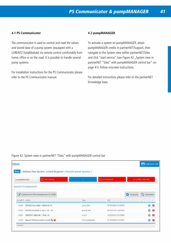
Figure 42: System view in partnerNET “Sites” with pumpMANAGER control bar
4 .1 PS Communicator
The communicator is used to control and read the values
and stored data of a pump system (equipped with a
LORENTZ DataModule) via remote control comfortably from
home, office or on the road. It is possible to handle several
pump systems.
For installation instructions for the PS Communicator please
refer to the PS Communicator manual.
4 .2 pumpMANAGER
To activate a system on pumpMANAGER, attain
pumpMANAGER credits in partnerNET/Support, then
navigate to the System view within partnerNET/Sites
and click “start service” (see Figure 42 „System view in
partnerNET “Sites” with pumpMANAGER control bar“ on
page 41). Follow onscreen instructions.
For detailed instructions please refer to the partnerNET
Knowledge base.