Embed Size (px)
Citation preview
925.439.8272 888.580.8272 www.bwc.comLPMNL-GNTRY REV. A
1
The LoPro gantry bracket enables LoPro linear motion
systems to be connected together to form gantry systems.
The gantry bracket allows numerous gantry system
configurations to be built by offering flexibility in the types
of LoPro systems that can be assembled together and in
the relative positions and orientations of the stages to
each other in the assembly.
Procedures for creating the most common stage
configurations for gantry systems are detailed in this
manual.
Users can create other gantry system configurations by
adding additional stages, reorienting the stages, and/or
using other sizes/types of LoPro systems.
LOPRO® GANTRY SYSTEM ASSEMBLY MANUAL
INDEXCompatibility Matrix . . . . . . . . . . . . . . . . . . . . . . . . . . .
X-Y Stage (Horizontal Y Stage) . . . . . . . . . . . . . . . . . .
X-Y Stage (Perpendicular Y Stage) . . . . . . . . . . . . . . .
X-Z Stage (Z Stage Connected by Support Beam) . . . .
X-Z Stage (Z Stage Connected by Carriage) . . . . . . . .
Size 1 Gantry Bracket System Parts . . . . . . . . . . . . . . .
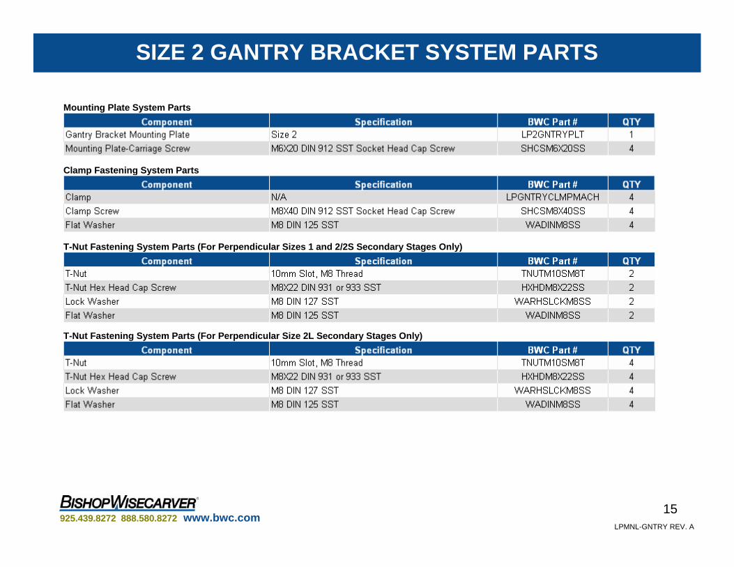
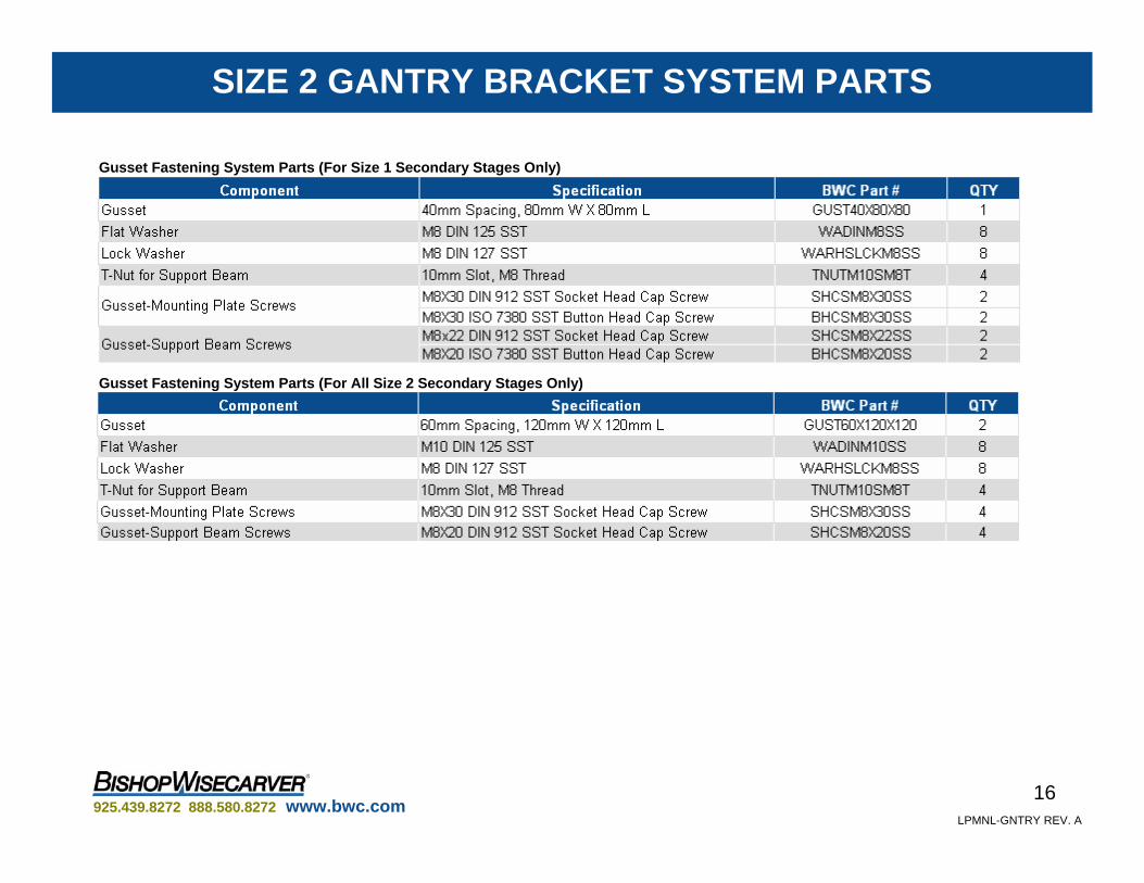
Size 2 Gantry Bracket System Parts . . . . . . . . . . . . . .
Size 3 Gantry Bracket System Parts . . . . . . . . . . . . . . .
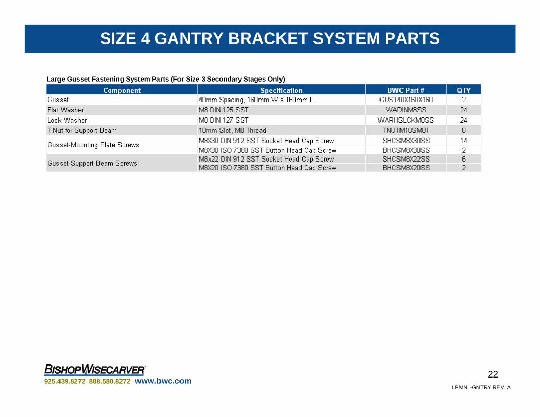
Size 4 Gantry Bracket System Parts . . . . . . . . . . . . . . .
2
3
7
10
13
14
15
17
20

925.439.8272 888.580.8272 www.bwc.comLPMNL-GNTRY REV. A
2
A wide variety of gantry brackets are available to form complete LoPro gantry systems. The following compatibility matrix shows which LoPro system sizes can be mated together, and in which orientations.
Additional parts may be required for complete assembly, including mounting plates, carriage screws, and clamp, T-nut or gusset fastening system parts. Please see pages 14 through 22 for more information.
COMPATIBILITY MATRIX
A. X-Y (Horizontal Y Stage) B. X-Y (Perpendicular Y Stage) C. X-Z (Z Stage Connected by Support Beam)
D. X-Z (Z Stage Connected by Carriage)
1. Size 2 lead screw or ball screw system.2. Size 1 and 2/2S secondary stages can be mounted with T-nuts in the perpendicular orientation on size 4 mounting plates, but cannot have side clamps
as reinforcement.3. Though it is physically possible to connect size 4 systems as secondary stages, this arrangement is not recommended.

925.439.8272 888.580.8272 www.bwc.comLPMNL-GNTRY REV. A
3
STEP 1Attach the bracket mounting plates to the carriages on both X stage LoPro systems. The plates should be oriented in the same direction.
(See pages 14 through 22 for a listing of gantry bracket system components)
STEP 2Position and affix the two X stage LoPro systems on their support surface(s) as desired. Ensure the systems are parallel and the two carriages are aligned with respect to the X-axis. The two X stage systems should be close enough together that the Y stage system’s support beam can reach the outside edges of the mounting plates.
STEP 3Place the Y stage system, carriage side up, on top of the X stage bracket mounting plates and oriented perpendicular to the X-axis.
Carriage
Bracket Mounting
Plate
Mounting Plate-Carriage Screws
X-Y STAGE (HORIZONTAL Y STAGE)
Bracket Mounting Plates
Y Stage

925.439.8272 888.580.8272 www.bwc.comLPMNL-GNTRY REV. A
4
STEP 4Hinge the clamps on the side T-slots on both sides of the Y stage system’s support beam. Align the clamps with the appropriate tapped mounting holes on the mounting plate (See the following diagrams for correct mounting holes for each clamp).
Note: If the X stage has two parallel systems, always verify that matching mounting holes on both mounting plates are used for theclamps, to prevent the Y stage from being mounted askew. Side T-Slot
Clamp
X-Y STAGE (HORIZONTAL Y STAGE)
AB
Size 1 Mounting Plate
A: Side 1 Clamp Mounting Holes for Size 1 Y Stage
B: Side 2 Clamp Mounting Holes for Size 1 Y Stage A: Side 1 Clamp Mounting Holes for Size 1 or 2 Y Stage
B: Side 2 Clamp Mounting Holes for Size 1 Y Stage
C: Side 2 Clamp Mounting Holes for Size 2 Y Stage
Clamp Mounting Holes
AB
A
A
B
B
C
C
Size 2 Mounting Plate

925.439.8272 888.580.8272 www.bwc.comLPMNL-GNTRY REV. A
5
D
Size 3 Mounting Plate Size 4 Mounting Plate
A: Side 1 Clamp Mounting Holes for Size 2 or 3 Y Stage
B: Side 1 Clamp Mounting Holes for Size 1 Y Stage
C: Side 2 Clamp Mounting Holes for Size 2 Y Stage
D: Side 2 Clamp Mounting Holes for Size 1 or 3 Y Stage
A: Side 1 Clamp Mounting Holes for Size 1 or 3 Y Stage
B: Side 2 Clamp Mounting Holes for Size 1 Y Stage
C: Side 2 Clamp Mounting Holes for Size 3 Y Stage
STEP 4 (cont’d)
X-Y STAGE (HORIZONTAL Y STAGE)
Clamp Mounting Holes
A
B
A
B
D
C
C
A
A
C
C
B
B

925.439.8272 888.580.8272 www.bwc.comLPMNL-GNTRY REV. A
6
STEP 5Insert a clamp screw with an M8 flat washer into the clearance hole on each clamp and bolt it into the mounting plate. It may be necessary to adjust the position of the Y stage system between turns of the screw to ensure that the clamps hold the support beam as evenly as possible.
Clamp Screw
M8 Flat Washer
Clamp
X-Y STAGE (HORIZONTAL Y STAGE)

925.439.8272 888.580.8272 www.bwc.comLPMNL-GNTRY REV. A
7
STEP 1Insert hex head cap screws with lock and flat washers through the clearance holes from the underside of the mounting plate. Loosely screw a T-nut onto each bolt from the top side of the mounting plate to keep them in place. The T-nuts should be located at matching holes on either side of the mounting plate.
Note: Two T-nuts are to be used on each mounting plate if the Y stage is size 1 or 2S and four are to be used for all other sizes. See the following diagrams for the appropriate mounting holes for each combination of mounting plate and secondary stage size. Size 1 Mounting Plate with T-Nuts Size 3 Mounting Plate with T-Nuts
T-Nut
M8 Lock Washer
M8 Flat Washer
Hex Head Cap
Screw
X-Y STAGE (PERPENDICULAR Y STAGE)
A
T-Nut and Clamp Mounting Holes
A: Clamp Mounting Holes for Size 1 Y Stage
X: T-Nut Holes for T-Slot 1 in Size 1 Y Stage
Y Stage Carriage Orientation
Size 1 Mounting Plate
A
X
X
Size 2 Mounting Plate
A: Clamp Mounting Holes for Size 1 or 2S Y Stage
X: T-Nut Holes for T-Slot 1 in Size 1, 2S, or 2L Y Stage
Y: T-Nut Holes for T-Slot 2 in Size 2L Y Stage
Y Stage Carriage Orientation
Y
Y
X
X
A
A

925.439.8272 888.580.8272 www.bwc.comLPMNL-GNTRY REV. A
8
Size 3 Mounting Plate
The size 3 mounting plate allows a secondary stage of any compatible size to be mounted perpendicularly with the carriage facing in either direction, depending on which set of clamp mounting holes or T-nut holes are used.
A1 or A2: Clamp Mounting Holes for Size 1 or 2S Y Stage
X: T-Nut Holes for T-Slot 1 in Size 1, 2S, or 2L Y Stage
Z1 or Z2: T-Nut Holes for T-Slot 2 in Size 2L Y Stage
Z1 and Z2: T-nut Holes for T-Slots 1 and 2 in Size 3 Y Stage.
X
A1 A2
Z2 Z1
STEP 1 (cont’d)T-Nut and Clamp Mounting Holes
X-Y STAGE (PERPENDICULAR Y STAGE)
Z2
A1 A2
Z1
X
Size 4 Mounting Plate
The size 4 mounting plate allows a secondary stage of any compatible size to be mounted perpendicularly with the carriage facing in either direction. Support side clamps cannot be attached, though, to any support beam on this mounting plate.
X, Y, or Z: T-Nut Holes for T-Slot 1 in Size 1 or 2S Y Stage
X and Y or Z: T-Nut Holes for T-Slots 1 and 2 in Size 2L Y Stage
Y and Z: T-Nut Holes for T-Slots 1 and 2 in Size 3 Y Stage
Z
YX
ZX
Y

925.439.8272 888.580.8272 www.bwc.comLPMNL-GNTRY REV. A
9
STEP 2Attach the mounting plates to the carriages on both X stage LoPro systems.
STEP 3Position and affix the two X stage LoPro systems on their support surface(s) as desired. Ensure the systems are parallel and the two carriages are aligned with respect to the X-axis. The two X stage systems should be close enough together that the Y stage system’s support beam can reach the outside edges of the mounting plates.
STEP 4
X-Y STAGE (PERPENDICULAR Y STAGE)
Size 1 Y Stage Size 3 Y Stage
Orient the Y stage system so that both its carriage and support beam are perpendicular to the X stage carriages, and one end of the support beam is near one of the outermost T-nuts. Align the Y stage system so that the outermost T-nut fits into the support beam’s side T-slot, then slide the Y stage system in the direction of the second X stage system, making sure all of the T-nuts on both mounting plates are captured in the T-slot.

925.439.8272 888.580.8272 www.bwc.comLPMNL-GNTRY REV. A
10
STEP 4.1(For Size 1 and 2S Y Stages Only)
Hinge clamps on the lowest T-slot on the support beam’s wide side, which should now be perpendicular to the mounting plate. Center them on the appropriate mounting holes on the mounting plate (see pg. 7) and lightly secure with the appropriate clamp screws and washers.
STEP 5
X-Y STAGE (PERPENDICULAR Y STAGE)
Lock down the T-nuts by using an open end wrench to tighten the hex head cap screws from the underside of the X stage mounting plates. Finish tightening the clamp screws, if applicable. It may be necessary to alternately tighten each set of fasteners, in small increments, and adjust the Y stage system’s position to ensure that it is aligned properly and that the fasteners are loaded evenly.

925.439.8272 888.580.8272 www.bwc.comLPMNL-GNTRY REV. A
11
STEP 1Position and affix the X stage LoPro system on its support surface as desired.
STEP 2Attach the bracket mounting plates to the carriage on the X stage LoPro system.
X-Z STAGE (Z STAGE CONNECTED BY SUPPORT BEAM)
STEP 3
Attach the gusset(s) to the mounting plate with the appropriate gusset-mounting plate fasteners. The exposed vertical face(s) of the gusset(s) should extend beyond the edge of the mounting plate and be parallel with the X-axis.
Notes:On 40X80X80 and 40X160X160 gussets, use the button head cap screws at the innermost slots on the gusset.
For secondary stages larger than size 1, two gussets need to be installed on the mounting plate. They should be side by side, with their exposed vertical faces coplanar.
M8 Lock Washer
Flat Washer
Socket Head Cap Screw
Button Head Cap Screw
Gusset
Gusset Vertical
Face

925.439.8272 888.580.8272 www.bwc.comLPMNL-GNTRY REV. A
12
STEP 4Loosely attach the T-nuts on the exterior of the gusset’s vertical side with the appropriate gusset-support beam fasteners.
Notes:On 40X80X80 and 40X160X160 gussets, use the button head cap screws at the innermost slots on the gusset.
For size 3 secondary stages, the two gussets present a total of four vertical columns that the T-nuts can be attached at. The T-nuts should be installed in two columns with one empty column in between, to ensure that the T-nuts are correctly spaced for the size 3 support beam.
STEP 5Orient the Z stage system to a vertical position so that that the bottom, wide side of the support beam faces the gusset’s vertical side. Align the support beam’s T-slots with the T-nuts, then slide the support beam along the side of the gusset to capture all of the T-nuts.
STEP 6When the Z stage is at its desired position relative to the X stage system, lock the T-nuts in place by tightening their associated screws.
M8 Lock Washer
Flat Washer
T-Nut
Button Head Cap Screw
Socket Head Cap Screw
X-Z STAGE (Z STAGE CONNECTED BY SUPPORT BEAM)
Vertical Z Stage

925.439.8272 888.580.8272 www.bwc.comLPMNL-GNTRY REV. A
13
STEP 1Perform steps 1-3 on page 11.
STEP 2Orient the Z stage system so that it is vertical relative to theX-axis and place its mounting plate against the gusset’s vertical side. Line up the appropriate mounting holes on the Z stage mounting plate with the gusset slots and secure the mounting plate with the appropriate gusset-mounting plate fasteners.
Note: On 40X80X80 and 40X160X160 gussets, use the button head cap screws at the innermost slots on the gusset.
Button Head Cap
ScrewSocket Head Cap Screw
Vertical Z Stage
Z Stage Mounting
Plate
M8 Lock Washer
Flat Washer
X-Z STAGE (Z STAGE CONNECTED BY CARRIAGE)

925.439.8272 888.580.8272 www.bwc.comLPMNL-GNTRY REV. A
14
Pages 14 -22 show the components relevant to each section of the gantry bracket system. The kit for each system contains the minimum number of parts necessary to incorporate each LoPro system into any of the gantry configurations shown in this manual.*
SIZE 1 GANTRY BRACKET SYSTEM PARTS
* Kits may not contain the same number of parts as the total for all lists combined for one size, as some parts are used in multiple gantry configurations.
Mounting Plate System Parts
Clamp Fastening System Parts
T-Nut Fastening System Parts (For Perpendicular Secondary Stages Only)
Gusset Fastening System Parts
925.439.8272 888.580.8272 www.bwc.comLPMNL-GNTRY REV. A
15
Clamp Fastening System Parts
T-Nut Fastening System Parts (For Perpendicular Sizes 1 and 2/2S Secondary Stages Only)
SIZE 2 GANTRY BRACKET SYSTEM PARTS
Mounting Plate System Parts
T-Nut Fastening System Parts (For Perpendicular Size 2L Secondary Stages Only)
925.439.8272 888.580.8272 www.bwc.comLPMNL-GNTRY REV. A
16
Gusset Fastening System Parts (For Size 1 Secondary Stages Only)
SIZE 2 GANTRY BRACKET SYSTEM PARTS
Gusset Fastening System Parts (For All Size 2 Secondary Stages Only)

925.439.8272 888.580.8272 www.bwc.comLPMNL-GNTRY REV. A
17
Mounting Plate System Parts
Clamp Fastening System Parts
T-Nut Fastening System Parts (For Perpendicular Sizes 1 and 2/2S Secondary Stages Only)
SIZE 3 GANTRY BRACKET SYSTEM PARTS
T-Nut Fastening System Parts (For Perpendicular Sizes 2L and 3 Secondary Stages Only)

925.439.8272 888.580.8272 www.bwc.comLPMNL-GNTRY REV. A
18
Gusset Fastening System Parts (For Size 1 Secondary Stages Only)
Gusset Fastening System Parts (For All Size 2 Secondary Stages Only)
Gusset Fastening System Parts (For Size 3 Secondary Stages Only)
SIZE 3 GANTRY BRACKET SYSTEM PARTS

925.439.8272 888.580.8272 www.bwc.comLPMNL-GNTRY REV. A
19
Large Gusset Fastening System Parts (For Size 3 Secondary Stages Only)
SIZE 3 GANTRY BRACKET SYSTEM PARTS

925.439.8272 888.580.8272 www.bwc.comLPMNL-GNTRY REV. A
20
Mounting Plate System Parts
Clamp Fastening System Parts
T-Nut Fastening System Parts (For Perpendicular Size 1 and 2/2S Secondary Stages Only)
SIZE 4 GANTRY BRACKET SYSTEM PARTS
T-Nut Fastening System Parts (For Perpendicular Size 2L and 3 Secondary Stages Only)

925.439.8272 888.580.8272 www.bwc.comLPMNL-GNTRY REV. A
21
Gusset Fastening System Parts (For Size 1 Secondary Stages Only)
Gusset Fastening System Parts (For Size 3 Secondary Stages Only)
SIZE 4 GANTRY BRACKET SYSTEM PARTS
925.439.8272 888.580.8272 www.bwc.comLPMNL-GNTRY REV. A
22
SIZE 4 GANTRY BRACKET SYSTEM PARTS
Large Gusset Fastening System Parts (For Size 3 Secondary Stages Only)


![Gantry Application - 三菱電機 Mitsubishi Electricdl.mitsubishielectric.co.jp/dl/fa/software/library/ssc/...1 BCN-B62005-668-A Gantry Application [System Configuration] Q06UDEHCPU](https://img.pdfslide.us/doc/110x75/5e9b3d90fd77d6555219c3bd/gantry-application-ee-mitsubishi-1-bcn-b62005-668-a-gantry-application.jpg)