Embed Size (px)
Citation preview
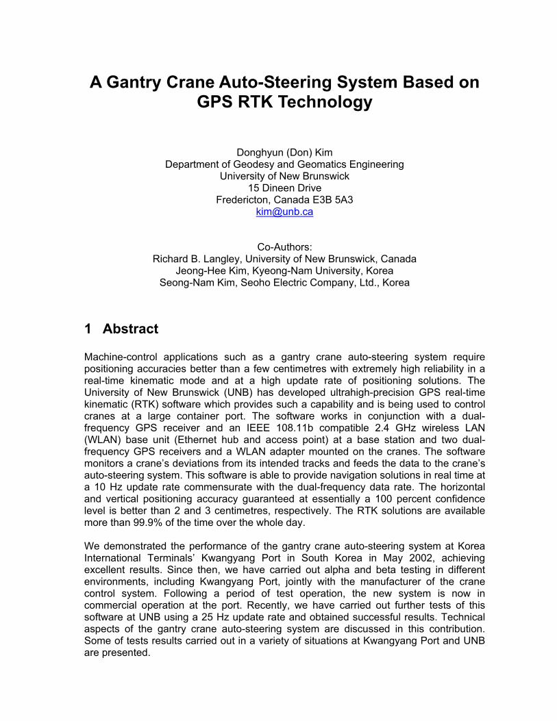
A Gantry Crane Auto-Steering System Based on GPS RTK Technology
Donghyun (Don) Kim
Department of Geodesy and Geomatics Engineering University of New Brunswick
15 Dineen Drive Fredericton, Canada E3B 5A3
Co-Authors: Richard B. Langley, University of New Brunswick, Canada
Jeong-Hee Kim, Kyeong-Nam University, Korea Seong-Nam Kim, Seoho Electric Company, Ltd., Korea
1 Abstract Machine-control applications such as a gantry crane auto-steering system require positioning accuracies better than a few centimetres with extremely high reliability in a real-time kinematic mode and at a high update rate of positioning solutions. The University of New Brunswick (UNB) has developed ultrahigh-precision GPS real-time kinematic (RTK) software which provides such a capability and is being used to control cranes at a large container port. The software works in conjunction with a dual-frequency GPS receiver and an IEEE 108.11b compatible 2.4 GHz wireless LAN (WLAN) base unit (Ethernet hub and access point) at a base station and two dual-frequency GPS receivers and a WLAN adapter mounted on the cranes. The software monitors a crane’s deviations from its intended tracks and feeds the data to the crane’s auto-steering system. This software is able to provide navigation solutions in real time at a 10 Hz update rate commensurate with the dual-frequency data rate. The horizontal and vertical positioning accuracy guaranteed at essentially a 100 percent confidence level is better than 2 and 3 centimetres, respectively. The RTK solutions are available more than 99.9% of the time over the whole day. We demonstrated the performance of the gantry crane auto-steering system at Korea International Terminals’ Kwangyang Port in South Korea in May 2002, achieving excellent results. Since then, we have carried out alpha and beta testing in different environments, including Kwangyang Port, jointly with the manufacturer of the crane control system. Following a period of test operation, the new system is now in commercial operation at the port. Recently, we have carried out further tests of this software at UNB using a 25 Hz update rate and obtained successful results. Technical aspects of the gantry crane auto-steering system are discussed in this contribution. Some of tests results carried out in a variety of situations at Kwangyang Port and UNB are presented.
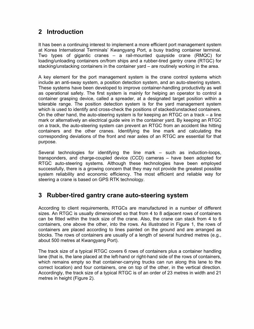
2 Introduction It has been a continuing interest to implement a more efficient port management system at Korea International Terminals’ Kwangyang Port, a busy trading container terminal. Two types of gigantic cranes – a rail-mounted quayside crane (RMQC) for loading/unloading containers on/from ships and a rubber-tired gantry crane (RTGC) for stacking/unstacking containers in the container yard – are routinely working in the area. A key element for the port management system is the crane control systems which include an anti-sway system, a position detection system, and an auto-steering system. These systems have been developed to improve container-handling productivity as well as operational safety. The first system is mainly for helping an operator to control a container grasping device, called a spreader, at a designated target position within a tolerable range. The position detection system is for the yard management system which is used to identify and cross-check the positions of stacked/unstacked containers. On the other hand, the auto-steering system is for keeping an RTGC on a track – a line mark or alternatively an electrical guide wire in the container yard. By keeping an RTGC on a track, the auto-steering system can prevent an RTGC from an accident like hitting containers and the other cranes. Identifying the line mark and calculating the corresponding deviations of the front and rear axles of an RTGC are essential for that purpose. Several technologies for identifying the line mark – such as induction-loops, transponders, and charge-coupled device (CCD) cameras – have been adopted for RTGC auto-steering systems. Although these technologies have been employed successfully, there is a growing concern that they may not provide the greatest possible system reliability and economic efficiency. The most efficient and reliable way for steering a crane is based on GPS RTK technology.
3 Rubber-tired gantry crane auto-steering system According to client requirements, RTGCs are manufactured in a number of different sizes. An RTGC is usually dimensioned so that from 4 to 8 adjacent rows of containers can be fitted within the track size of the crane. Also, the crane can stack from 4 to 6 containers, one above the other, into the rows. As illustrated in Figure 1, the rows of containers are placed according to lines painted on the ground and are arranged as blocks. The rows of containers are usually of a length of several hundred metres (e.g., about 500 metres at Kwangyang Port). The track size of a typical RTGC covers 6 rows of containers plus a container handling lane (that is, the lane placed at the left-hand or right-hand side of the rows of containers, which remains empty so that container-carrying trucks can run along this lane to the correct location) and four containers, one on top of the other, in the vertical direction. Accordingly, the track size of a typical RTGC is of an order of 23 metres in width and 21 metres in height (Figure 2).
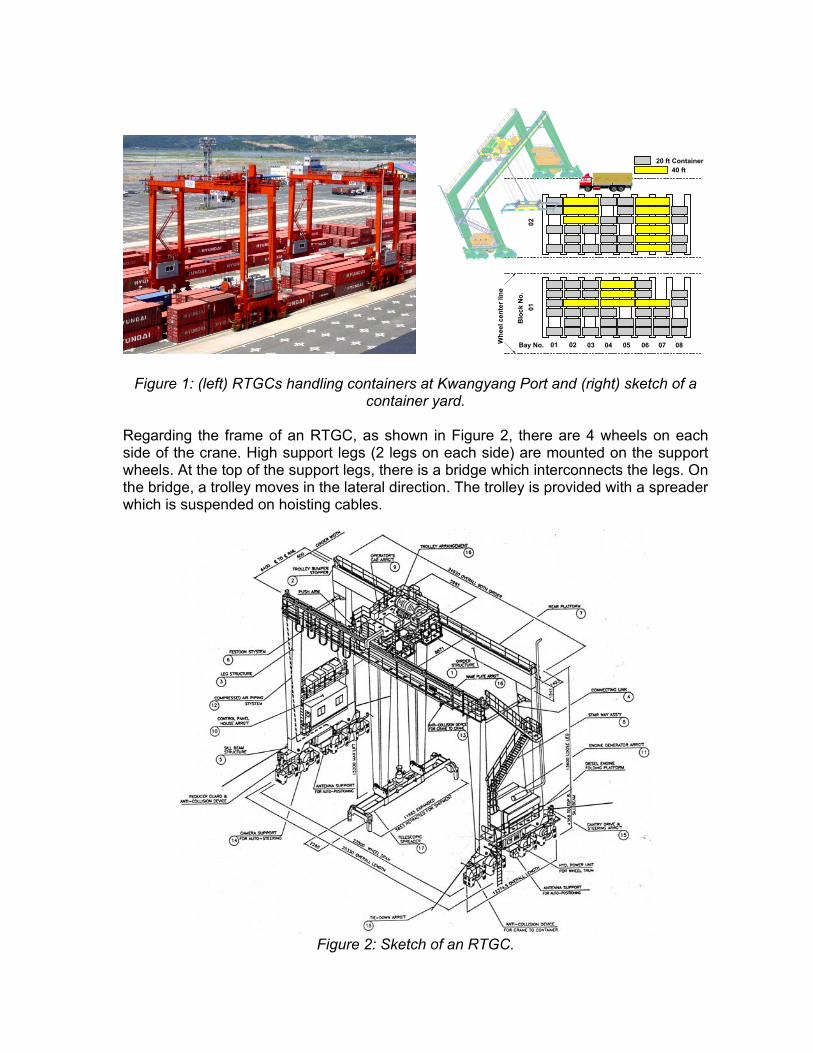
Figure 1: (left) RTGCs handling containers at Kwangyang Port and (right) sketch of a
container yard. Regarding the frame of an RTGC, as shown in Figure 2, there are 4 wheels on each side of the crane. High support legs (2 legs on each side) are mounted on the support wheels. At the top of the support legs, there is a bridge which interconnects the legs. On the bridge, a trolley moves in the lateral direction. The trolley is provided with a spreader which is suspended on hoisting cables.
Figure 2: Sketch of an RTGC.
20 ft Container40 ft
01 02 03 04 05 06 07 08Bay No.
0102
Blo
ck N
o.
Whe
el c
ente
r lin
e
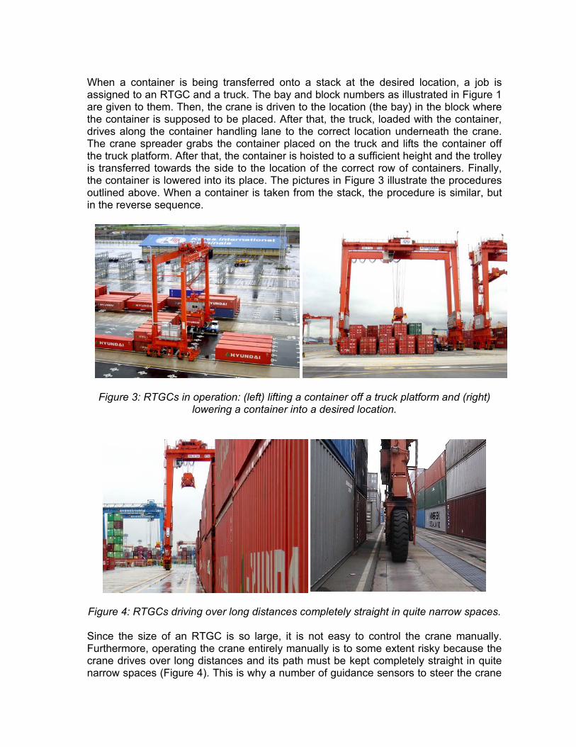
When a container is being transferred onto a stack at the desired location, a job is assigned to an RTGC and a truck. The bay and block numbers as illustrated in Figure 1 are given to them. Then, the crane is driven to the location (the bay) in the block where the container is supposed to be placed. After that, the truck, loaded with the container, drives along the container handling lane to the correct location underneath the crane. The crane spreader grabs the container placed on the truck and lifts the container off the truck platform. After that, the container is hoisted to a sufficient height and the trolley is transferred towards the side to the location of the correct row of containers. Finally, the container is lowered into its place. The pictures in Figure 3 illustrate the procedures outlined above. When a container is taken from the stack, the procedure is similar, but in the reverse sequence.
Figure 3: RTGCs in operation: (left) lifting a container off a truck platform and (right)
lowering a container into a desired location.
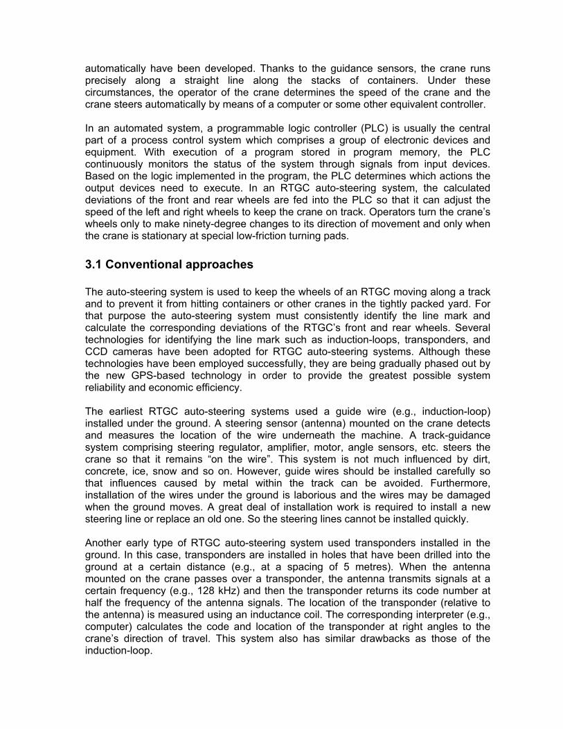
Figure 4: RTGCs driving over long distances completely straight in quite narrow spaces. Since the size of an RTGC is so large, it is not easy to control the crane manually. Furthermore, operating the crane entirely manually is to some extent risky because the crane drives over long distances and its path must be kept completely straight in quite narrow spaces (Figure 4). This is why a number of guidance sensors to steer the crane
automatically have been developed. Thanks to the guidance sensors, the crane runs precisely along a straight line along the stacks of containers. Under these circumstances, the operator of the crane determines the speed of the crane and the crane steers automatically by means of a computer or some other equivalent controller. In an automated system, a programmable logic controller (PLC) is usually the central part of a process control system which comprises a group of electronic devices and equipment. With execution of a program stored in program memory, the PLC continuously monitors the status of the system through signals from input devices. Based on the logic implemented in the program, the PLC determines which actions the output devices need to execute. In an RTGC auto-steering system, the calculated deviations of the front and rear wheels are fed into the PLC so that it can adjust the speed of the left and right wheels to keep the crane on track. Operators turn the crane’s wheels only to make ninety-degree changes to its direction of movement and only when the crane is stationary at special low-friction turning pads.
3.1 Conventional approaches The auto-steering system is used to keep the wheels of an RTGC moving along a track and to prevent it from hitting containers or other cranes in the tightly packed yard. For that purpose the auto-steering system must consistently identify the line mark and calculate the corresponding deviations of the RTGC’s front and rear wheels. Several technologies for identifying the line mark such as induction-loops, transponders, and CCD cameras have been adopted for RTGC auto-steering systems. Although these technologies have been employed successfully, they are being gradually phased out by the new GPS-based technology in order to provide the greatest possible system reliability and economic efficiency. The earliest RTGC auto-steering systems used a guide wire (e.g., induction-loop) installed under the ground. A steering sensor (antenna) mounted on the crane detects and measures the location of the wire underneath the machine. A track-guidance system comprising steering regulator, amplifier, motor, angle sensors, etc. steers the crane so that it remains “on the wire”. This system is not much influenced by dirt, concrete, ice, snow and so on. However, guide wires should be installed carefully so that influences caused by metal within the track can be avoided. Furthermore, installation of the wires under the ground is laborious and the wires may be damaged when the ground moves. A great deal of installation work is required to install a new steering line or replace an old one. So the steering lines cannot be installed quickly. Another early type of RTGC auto-steering system used transponders installed in the ground. In this case, transponders are installed in holes that have been drilled into the ground at a certain distance (e.g., at a spacing of 5 metres). When the antenna mounted on the crane passes over a transponder, the antenna transmits signals at a certain frequency (e.g., 128 kHz) and then the transponder returns its code number at half the frequency of the antenna signals. The location of the transponder (relative to the antenna) is measured using an inductance coil. The corresponding interpreter (e.g., computer) calculates the code and location of the transponder at right angles to the crane’s direction of travel. This system also has similar drawbacks as those of the induction-loop.
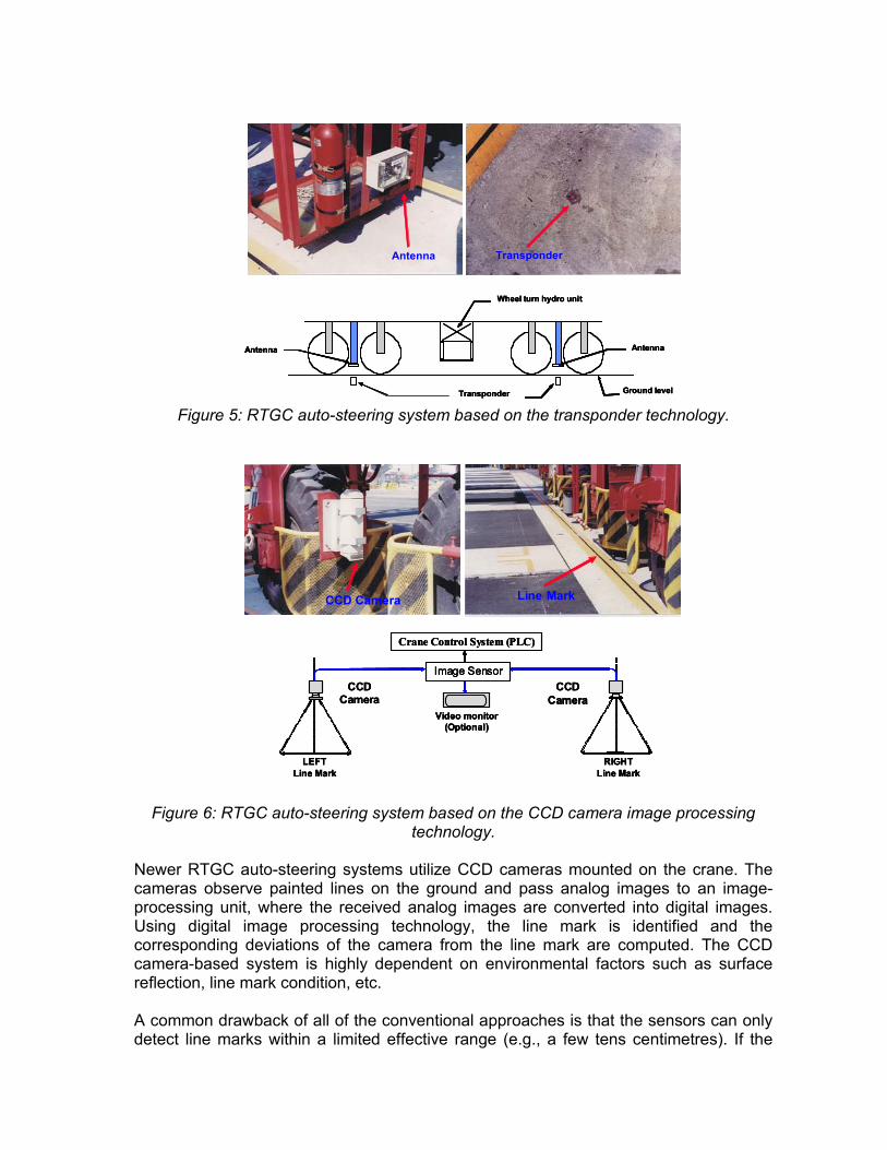
Figure 5: RTGC auto-steering system based on the transponder technology.
Figure 6: RTGC auto-steering system based on the CCD camera image processing
technology. Newer RTGC auto-steering systems utilize CCD cameras mounted on the crane. The cameras observe painted lines on the ground and pass analog images to an image-processing unit, where the received analog images are converted into digital images. Using digital image processing technology, the line mark is identified and the corresponding deviations of the camera from the line mark are computed. The CCD camera-based system is highly dependent on environmental factors such as surface reflection, line mark condition, etc. A common drawback of all of the conventional approaches is that the sensors can only detect line marks within a limited effective range (e.g., a few tens centimetres). If the
Wheel turn hydro unit
Antenna
Ground levelTransponder
Antenna
Antenna Transponder
Wheel turn hydro unit
Antenna
Ground levelTransponder
Antenna
Wheel turn hydro unit
Antenna
Ground levelTransponder
Antenna
Antenna Transponder
Video monitor (Optional)
LEFTLine Mark
RIGHTLine Mark
CCDCamera
Crane Control System (PLC)
Image SensorCCD
Camera
CCD Camera Line Mark
Video monitor (Optional)
LEFTLine Mark
RIGHTLine Mark
CCDCamera
Crane Control System (PLC)
Image SensorCCD
CameraVideo monitor
(Optional)
LEFTLine Mark
RIGHTLine Mark
CCDCamera
Crane Control System (PLC)
Image SensorCCD
Camera
CCD Camera Line Mark
crane exceeds this range for some reason, there is no way to get the crane back on track automatically.
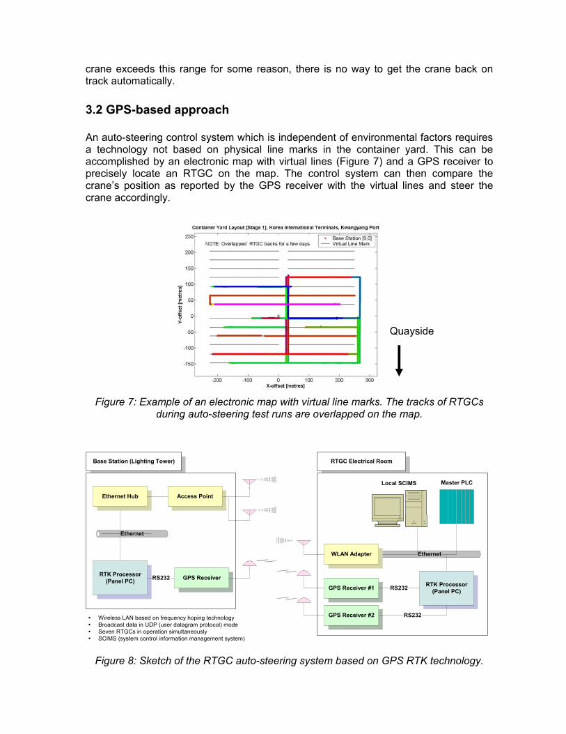
3.2 GPS-based approach An auto-steering control system which is independent of environmental factors requires a technology not based on physical line marks in the container yard. This can be accomplished by an electronic map with virtual lines (Figure 7) and a GPS receiver to precisely locate an RTGC on the map. The control system can then compare the crane’s position as reported by the GPS receiver with the virtual lines and steer the crane accordingly.
Figure 7: Example of an electronic map with virtual line marks. The tracks of RTGCs during auto-steering test runs are overlapped on the map.
Figure 8: Sketch of the RTGC auto-steering system based on GPS RTK technology.
Quayside
RTGC Electrical Room
Ethernet
RTK Processor(Panel PC)
WLAN Adapter
GPS Receiver #1
GPS Receiver #2
RS232
RS232
Local SCIMS Master PLC
Base Station (Lighting Tower)
Ethernet
RTK Processor(Panel PC)
Access Point
GPS ReceiverRS232
Ethernet Hub
Wireless LAN based on frequency hoping technologyBroadcast data in UDP (user datagram protocol) modeSeven RTGCs in operation simultaneouslySCIMS (system control information management system)
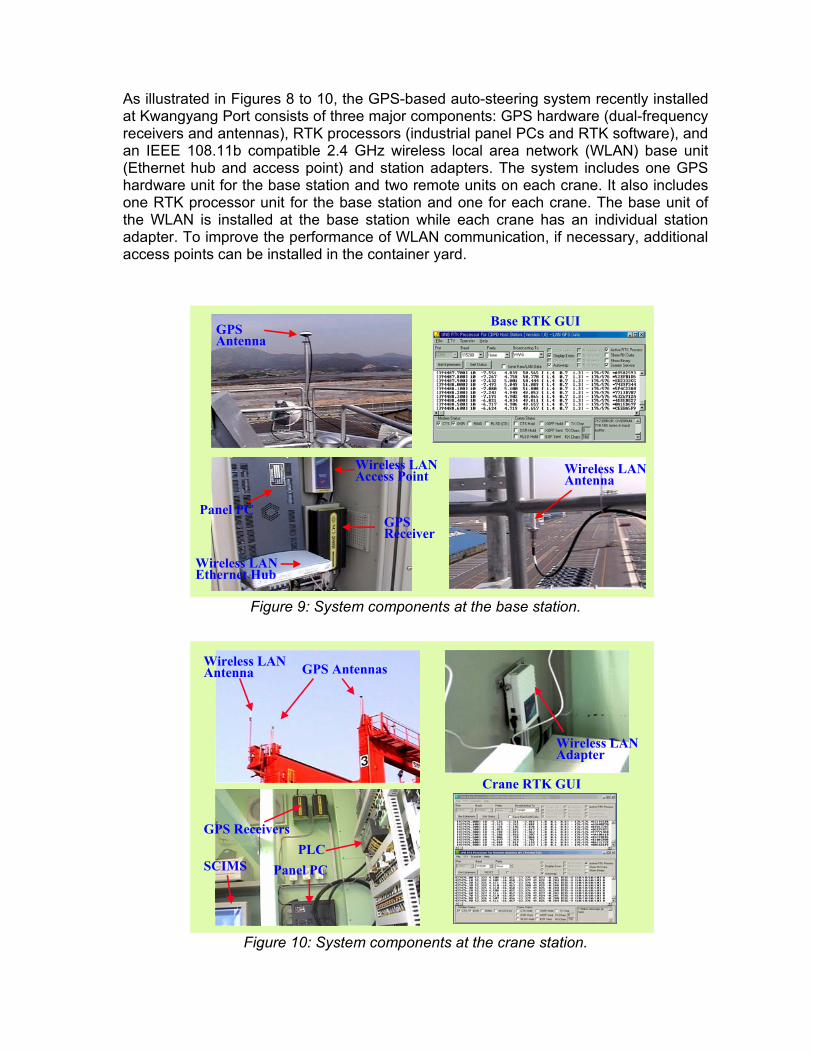
As illustrated in Figures 8 to 10, the GPS-based auto-steering system recently installed at Kwangyang Port consists of three major components: GPS hardware (dual-frequency receivers and antennas), RTK processors (industrial panel PCs and RTK software), and an IEEE 108.11b compatible 2.4 GHz wireless local area network (WLAN) base unit (Ethernet hub and access point) and station adapters. The system includes one GPS hardware unit for the base station and two remote units on each crane. It also includes one RTK processor unit for the base station and one for each crane. The base unit of the WLAN is installed at the base station while each crane has an individual station adapter. To improve the performance of WLAN communication, if necessary, additional access points can be installed in the container yard.
Figure 9: System components at the base station.
Figure 10: System components at the crane station.
GPSAntenna
Wireless LANAntenna
GPSReceiver
Panel PC
Wireless LANAccess Point
Base RTK GUI
Wireless LANEthernet Hub
GPSAntenna
Wireless LANAntenna
GPSReceiver
Panel PC
Wireless LANAccess Point
Base RTK GUI
Wireless LANEthernet Hub
Wireless LANAntenna GPS Antennas
GPS ReceiversPLC
Panel PC
Wireless LANAdapter
Crane RTK GUI
SCIMS
Wireless LANAntenna GPS Antennas
GPS ReceiversPLC
Panel PC
Wireless LANAdapter
Crane RTK GUI
SCIMS

Note that one GPS antenna and receiver unit mounted on the crane monitors the deviations of the crane’s front wheels from its track and the other is used for monitoring those of the rear wheels, vice versa. Therefore, the orientation as well as the location of the crane can be computed precisely.
4 Auto-steering test runs Since the first demonstration of the RTK-based gantry crane auto-steering system at Kwangyang Port in May 2002, a number of alpha and beta tests have been carried out in different environments, including Kwangyang Port and at the UNB Fredericton campus. Seven RTGCs equipped with the system are now in commercial operation at the port. Two examples which show crane dynamics induced by typical crane operations (e.g., auto-steering and container lifting) are illustrated in Figures 11 to 14. During the test runs in these examples, the deviations of the GPS antennas mounted on the crane (eventually, those of an RTGC’s front and rear wheels) from the virtual lines were computed in real-time and fed into the PLC so that it can adjust the speed of the front and rear wheels to keep the crane on track.
Figure 11: (left) Tracks of RTGC test runs (overlapped on the container yard layout) and (right) magnified tracks of the test runs. The sinusoidal pattern of wheel deviation is
typical in auto-steering mode. The effects of lifting a container are oscillations along the Y-offset axis (top panel in Figure 11(right)).
The test run of the bottom panel in Figure 11(right) was carefully carried out to monitor the performance of the system under multipath-rich environment and transient signal-interruption due to obstacles in the vicinity of an RTGC. As a matter of fact, the locations of the test area where the test run was conducted are close to the quayside, where the gigantic RMQCs, of the order of 50 metres in height, operate (Figure 13). We have confirmed that the auto-steering system performs extremely well in such an environment so hostile to the GPS RTK system.
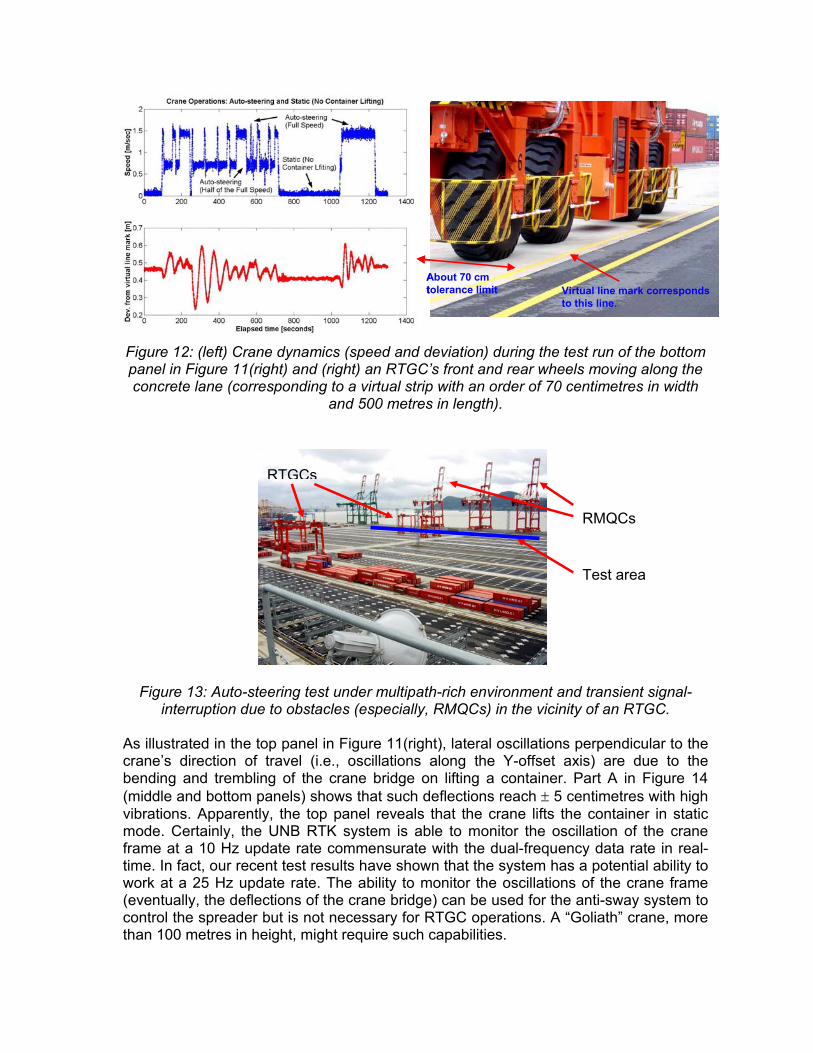
Figure 12: (left) Crane dynamics (speed and deviation) during the test run of the bottom panel in Figure 11(right) and (right) an RTGC’s front and rear wheels moving along the concrete lane (corresponding to a virtual strip with an order of 70 centimetres in width
and 500 metres in length).
Figure 13: Auto-steering test under multipath-rich environment and transient signal-
interruption due to obstacles (especially, RMQCs) in the vicinity of an RTGC. As illustrated in the top panel in Figure 11(right), lateral oscillations perpendicular to the crane’s direction of travel (i.e., oscillations along the Y-offset axis) are due to the bending and trembling of the crane bridge on lifting a container. Part A in Figure 14 (middle and bottom panels) shows that such deflections reach ± 5 centimetres with high vibrations. Apparently, the top panel reveals that the crane lifts the container in static mode. Certainly, the UNB RTK system is able to monitor the oscillation of the crane frame at a 10 Hz update rate commensurate with the dual-frequency data rate in real-time. In fact, our recent test results have shown that the system has a potential ability to work at a 25 Hz update rate. The ability to monitor the oscillations of the crane frame (eventually, the deflections of the crane bridge) can be used for the anti-sway system to control the spreader but is not necessary for RTGC operations. A “Goliath” crane, more than 100 metres in height, might require such capabilities.
Virtual line mark correspondsto this line.
About 70 cm tolerance limit Virtual line mark corresponds
to this line.
About 70 cm tolerance limit
RMQCs
Test area
RTGCs
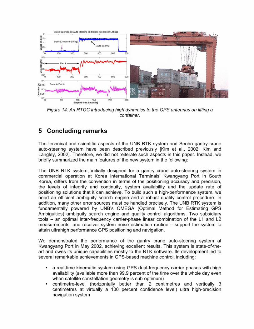
Figure 14: An RTGC introducing high dynamics to the GPS antennas on lifting a container.
5 Concluding remarks The technical and scientific aspects of the UNB RTK system and Seoho gantry crane auto-steering system have been described previously [Kim et al., 2002; Kim and Langley, 2002]. Therefore, we did not reiterate such aspects in this paper. Instead, we briefly summarized the main features of the new system in the following: The UNB RTK system, initially designed for a gantry crane auto-steering system in commercial operation at Korea International Terminals’ Kwangyang Port in South Korea, differs from the convention in terms of the positioning accuracy and precision, the levels of integrity and continuity, system availability and the update rate of positioning solutions that it can achieve. To build such a high-performance system, we need an efficient ambiguity search engine and a robust quality control procedure. In addition, many other error sources must be handled precisely. The UNB RTK system is fundamentally powered by UNB’s OMEGA (Optimal Method for Estimating GPS Ambiguities) ambiguity search engine and quality control algorithms. Two subsidiary tools – an optimal inter-frequency carrier-phase linear combination of the L1 and L2 measurements, and receiver system noise estimation routine – support the system to attain ultrahigh performance GPS positioning and navigation. We demonstrated the performance of the gantry crane auto-steering system at Kwangyang Port in May 2002, achieving excellent results. This system is state-of-the-art and owes its unique capabilities mostly to the RTK software. Its development led to several remarkable achievements in GPS-based machine control, including:
a real-time kinematic system using GPS dual-frequency carrier phases with high availability (available more than 99.9 percent of the time over the whole day even when satellite constellation geometry is sub-optimum)
centimetre-level (horizontally better than 2 centimetres and vertically 3 centimetres at virtually a 100 percent confidence level) ultra high-precision navigation system
high navigation solution update rate (10 Hz update rate commensurate with the dual-frequency data rate).
UNB has explored the capabilities of the RTK software in new GPS applications. Recently, tests of this software for deformation monitoring have been carried out at Highland Valley Copper Mine in British Columbia, Canada. Also, tests to investigate the performance of the software under long-baseline situations including on-land and offshore environments are being conducted. Dedicated UHF point-to-point, WLAN and LAN communications have been used for real-time testing. From the initial investigations for new RTK applications, a second generation of the UNB RTK software has been developed which improves system performance for different applications. One of the main features of the new software is dual-mode communication which can switch between WLAN and a dedicated UHF radio system automatically if either communication link is not available. As a result, dual-mode communication increases availability of the RTK system and hence, it is able to provide seamless RTK services for clients moving through different environments. Seoho Electric Co., Ltd. has been supplying crane control systems to many harbours around the world and continues to develop more advanced systems adopting new technologies for a variety of cranes. Seoho is now offering the GPS RTK-based auto-steering system which replaces its previous auto-steering system using the CCD camera image processing technology. Recently, Seoho has delivered seven RTGCs equipped with the new auto-steering system to its client at Kwangyang Port.
6 Acknowledgements Some parts of the research reported in this paper were carried out under contract specifically for the GPS RTK software development for a gantry crane auto-steering system. The support of Seoho Electric Co., Ltd. and the Center for Intelligent & Integrated Port Management Systems (CIIPMS) in Dong-A University are gratefully acknowledged. The first and second authors would like to express their appreciation to the Geodetic Survey Division of Natural Resources Canada and NavCom Technology for the provision of GPS receivers and antennas for use during the real-time field testing of the software at UNB. Further information on the gantry crane auto-steering system (either a conventional or GPS-based approach) can be found on the following Web sites:
Seoho: http://www.seoho.com/applications/crane.html. Götting KG: http://www.goetting.biz/en/products/start.html. UNB: http://gge.unb.ca/Personnel/Kim/Kim.CRANE.html.
7 References Kim, D., R. B. Langley, and S. Kim (2002). “High-precision crane guidance: Shipyard
giants.” GPS World, Vol. 13, No. 9, September, pp. 28-34. Kim, D. and R. B. Langley (2002). “On ultrahigh-precision positioning and navigation.”
Proceedings of ION GPS 2002, 15th International Technical Meeting of the Satellite Division of The Institute of Navigation, Portland, Oregon, 24-27 September, pp. 904-913.