Embed Size (px)
Citation preview

STRUCTURE GEOTECHNICAL REPORT
LONGMEADOW PARKWAY BRIDGE CORRIDOR
RETAINING WALL
SN: RW-O1, STA. 2094+70 TO 2096+70
IDOT JOB No. P-91-393-94, SECTION: 94-00215-01-ES
KANE COUNTY, ILLINOIS
for
McDonough Associates, Inc.
130 East Randolph Street, Suite 1000
Chicago, IL 60601
(312) 946-8600
submitted by
Wang Engineering, Inc.
1145 North Main Street
Lombard, IL 60148
(630) 953-9928
March 8, 2011
WE! Ref. No. 201-23-01 Retaining Wall No. 1
Technical Report Documentation Page
‘A,WangE.ngineanng
1. Title and Subtitle 2. Report DateStructure Geotechnical Report March 8, 2011Longrneadow Parkway Bridge Corridor 3. Report Type SGR RGRRetaining Wall No. I L Draft Final Revised
4. Route! Section / County 5. IDOT Job / Contract No.Longmeadow Parkway! 94-00215-01-ES! Kane Job No. P-91-393-94
Contract:6. PTB / Item No. 5. Existing Structure Number(s) 6. Proposed Structure Number(s)
N/A N/A SN. RW-0l
7. Prepared by Contributor(s) Contact Phone NumberWang Engineering, Inc. Author: Mohammed Kothawala, P.E. (630) 953-9928 ext 361145 N Main Street QC/QA: Jeriy W.H. Wang, PhD, P.E.Lombard, IL 60148 PM: Mohammed Kothawala, P.E.
9. Prepared for Design / Structural Engineer Contact Phone NumberMcDonough Associates, Inc. Gerald Koylass, S.E., P.E. (312) 946-8600130 East Randolph StreetSuite 1000Chicago, IL 60601
10. Abstract
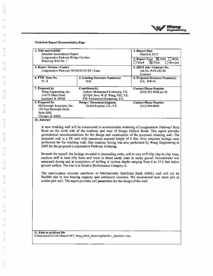
A new retaining wall will be constructed to accommodate widening of Longmeadow Parkway! BolzRoad on the north side of the roadway and west of Sleepy Hollow Road. This report providesgeotechnical recommendations for the design and construction of the proposed retaining wall. Theproposed wall is a fill wall with maximum exposed height of 6 feet. Four structure borings wereperformed for the retaining wall. One roadway boring was also performed by Wang Engineering in2005 forthe proposed Longmeadow Parkway widening.
Beneath the topsoil, the borings revealed in descending order, soft to very stiff silty clay to clay loam,medium stiff to hard silty loam and loose to dense sandy loam to sandy gravel. Groundwater wasmeasured during and at completion of drilling at various depths ranging from 6 to 37.5 feet belowground surface. The site is in Seismic Performance Category A.
The cast-in-place concrete cantilever or Mechanically Stabilized Earth (MSE) wall will not befeasible due to low bearing capacity and settlement concerns. We recommend steel sheet pile orsoldier pile wall. The report provides soil parameters for the design of the wall.
11. Path to archived fileS:\Netprojects\20 1230 1\Report\ RPT_Wang_MAK_RetainingWallNo. I_March20 11 .doc

rWang -
Engineering
TABLE OF CONTENTS
1.0 INTRODUCTION 1
2.0 METHODS OF INVESTIGATION 1
3.0 RESULTS OF OF FIELD AND LABORATORY INVESTIGATIONS 3
4.0 ANALYSIS AND RECOMMENDATIONS 4
5.0 CONSTRUCTION CONSIDERATIONS 8
6.0 QUALIFICATIONS 9
REFERENCESEXHIBITS
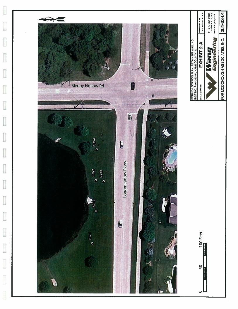
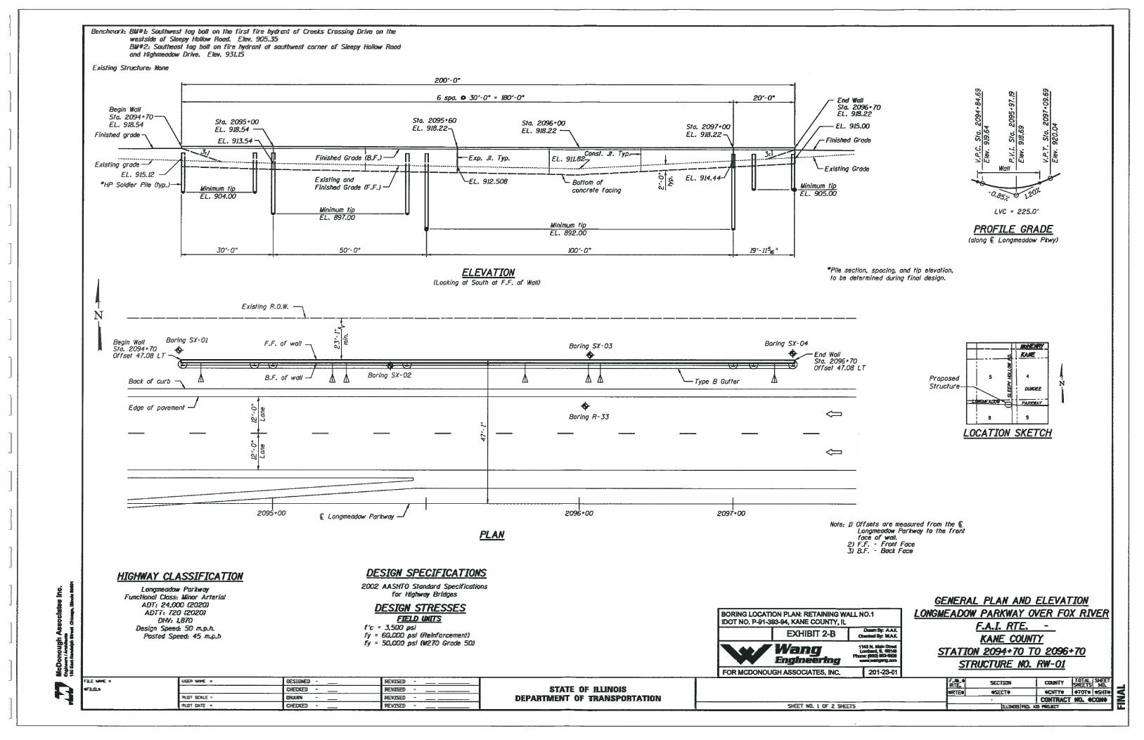
1. Site Location Map2. Boring Locations Plan3. Subsurface Soil Data Profile
APPENDIX ABoring Logs
APPENDIX BLaboratory Test Results
APPENDIX CGlobal Stability Analysis Results
‘F1145 North Main Streetaug Lombard, Illinois 60148
Engineering Phone (630) 953-9928www.wangeng.com
STRUCTURE GEOTECHNICAL REPORT
LONGMEADOW PARKWAY BRIDGE CORRIDOR
RETAINING WALL
SN: RW-01, STA. 2094+70 TO 2096+70
IDOT Job No. P-91-393-94, SECTION: 94-00215-01-ES
KANE COUNTY, ILLINOIS
FOR
MCDONOUGH ASSOCIATES, INC.
1.0 INTRODUCTION
This report presents the results of Wang Engineering, Inc. (Wang) subsurface investigation,
laboratory testing, and geotechnical evaluation for the proposed Retaining Wall No. 1 located on
the north side of Longmeadow Parkway and immediately west of Sleepy Hollow Road in the
City of Algonquin, Illinois. The project area is located in the northeastern part of Kane County.
On the USGS “Crystal Lake” Quadrangle Map, the proposed Retaining Wall No. 1 is located
in the SE ¼ of Section 5, Tier 42 North, Range 8 East. A Site Location Map is presented as
Exhibit 1.
The purpose of our investigation was to characterize the site subsurface soil and groundwater
conditions and provide geotechnical analyses and recommendations for the design and
construction of the new wall.
2.0 METHODS OF INVESTIGATION
The following sections outline the subsurface soil and groundwater investigation and
laboratory testing performed by Wang.
Geotcc1,nical . Con.ctruciion . Er1viron1n’ntLz1ijtia/ir.i £zzi;i-inz Servicts Since 1 9S’2
Longmeadow Parkway Bridge CorridorRetaining Wall No. 1Wang No. 201-23-01 WangMarch 8, 2011 W EnginringPage 2
2.1 Subsurface Investigation
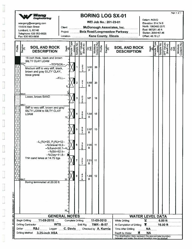
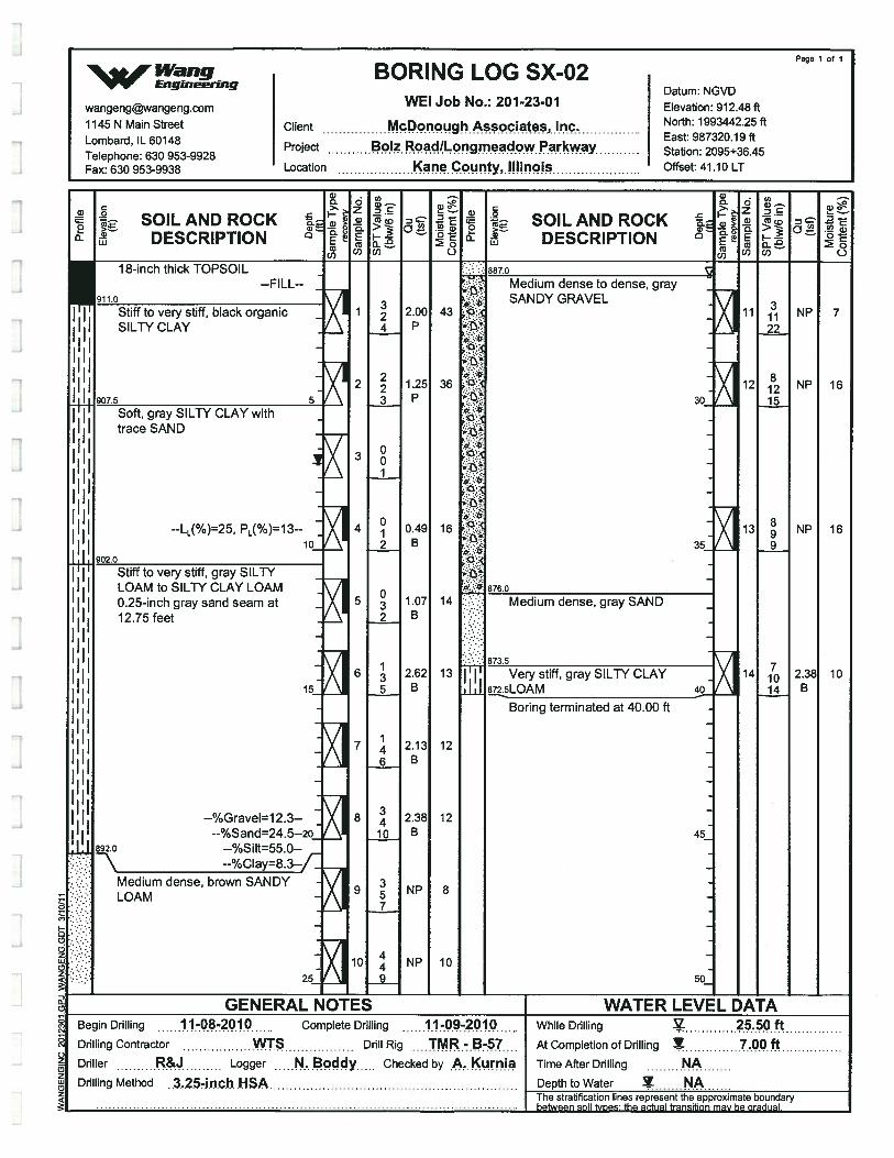
Four structure borings (SX-0 1 through SX-04) were drilled along the Longmeadow Parkway
alignment between approximate Stations 2094+50 2097+00 on November 8 and 9, 2010.
Borings were marked in the field based on the proposed locations approved by McDonough
Associates, Inc. (MAT). The borings were performed on the grass area south of a pond from
elevations 912.04 and 915.59 feet. Borings SX-01 and SX-04 were drilled to depths of 20
feet below ground surface (bgs) and Borings SX-02 and SX-03 to depths of 40 feet bgs.
A truck-mounted drilling rig was used to complete the structure borings. Drilling was
conducted with hollow stem augers to advance and maintain an open borehole. Soil sampling
was performed according to AASHTO T 206, “Penetration Test and Split Barrel Sampling of
Soils.” The soil was sampled at 2.5-foot intervals to a depth of 30 feet bgs and at 5-foot
interval below 30 feet to boring termination depths. Samples collected from each sampling
interval were placed in sealed glass jars. As-drilled northing, easting, coordinates, stations,
offsets, and elevations were determined by Wang based on MicroStation drawing provided
by MAT, and are shown in the boring logs (Appendix A).
Field boring logs, prepared and maintained by a Wang soil inspector, included lithological
descriptions, visual-manual soil classifications, results of Rimac or pocket penetrometer
unconfined compression tests, and Standard Penetration Tests (SPT) recorded as blows per 6
inches of penetration.
Groundwater levels were measured while drilling and at the completion of drilling
operations. Upon completion, the boreholes were backfilled with bentonite chips mixed with
soil cuttings. In addition, the ground surface was restored as close as possible to the original
condition.
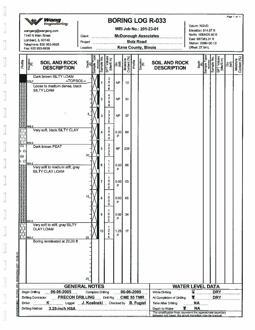
In addition to the structure borings, one roadway boring, R-033 was performed by Wang in 2005
for MAI for Bolz Road/Longmeadow Parkway roadway project. This roadway boring was
considered to supplement the soil descriptions in the proposed retaining wall area. Boring R-033
was drilled from elevation 914.97 feet to a depth of 20 feet bgs.
Longmeadow Parkway Bridge CorridorRetaining Wall No. IWang No. 201-23-01 II’angMarch 8,2011 EngineeringPage 3
2.2 Laboratory Testing
Samples obtained in the field were transported to our in-house laboratory in Lombard, Illinois.
The testing program included moisture content (AASHTO T 265) on all soil samples. Atterberg
limits tests (AASHTO T 89-96 & T 90-96) and particle-size analyses (AASHTO T 88-97)
were performed on selected soil samples. The laboratory test results are shown on the boring
logs (Appendix A) and included in Appendix B. All field visual classifications were verified in
the laboratory.
The soil samples will be retained in our laboratory for 60 days following the final report
submittal. After that, the samples will be discarded unless a specific written request is
received as to their disposition.
3.0 RESULTS OF FIELD AND LABORATORY INVESTIGATIONS
Detailed descriptions of the soil conditions encountered during the subsurface investigation are
presented in the attached Boring Logs (Appendix A) and in the Subsurface Soil Data Profile
(Exhibit 3). Please note that strata contact lines represent approximate boundaries between soil
types. The actual transition between soil types in the field may be gradual in horizontal and
vertical directions.
3.1 Soil Conditions
Near the surface, the borings encountered 12 to 18 inches of black silty clay loam topsoil. In
descending order, the general lithologic succession encountered beneath the topsoil includes: 1) soft
to very stiff silty clay to clay loam; 2) medium stiff to hard silty loam; and 3) loose to dense sandy
loam to sandy gravel.
1) Soft to very stiffsilty clay to clay loam
Beneath the topsoil, the borings encountered 4.8 to 11.7 feet of soft to very stiff, black, brown, and
gray silty clay to clay loam with some organic material. The soil has unconfined compression strength
(Qu) values of 0.49 to 3.5 tsf with an average of 1.7 tsf and moisture contents (MC) of 13 to 43% with
an average of 23%. Laboratory index testing on samples from this layer shows Liquid Limit (LL)
value of 25% and Plastic Limit (PL) value of 13%.
Longmeadow Parkway Bridge CorridorRetaining Wall No. IWang No 201-23-01 IVarigMarch 8,2011 EngineeringPage 4
2) Medium stjff to hard silty loam
At elevations of 897.3 to 907.8 feet (7.7 to 14.7 bgs), the borings advanced through medium stiff to
hard, brown and gray silty loam. The soil has Qu values of 0.74 to 4.1 tsf with an average of 2.2 tsf
and MC of 10 to 19% with an average of 13%. Laboratory index testing on samples from this layer
shows Liquid Limit (LL) values of 18 to 20% and Plastic Limit (PL) value of 12%.
3) Loose to dense sandy loam to sandy gravel
Beneath silty loam layer, the boring revealed loose to dense, brown and gray sandy loam to sandy
loam. This layer has an N-value of 8 to 49 blows/foot with an average of 21 blows/foot.
Exception should be noted in Borings SX-03 and R-033 where layers of peat and very soft silty clay
loam material with high moisture encountered between elevations 897.0 and 906.5 ft (3.0 to 18.0 ft
bgs). The peat material has Qu values of 0.41 to 0.74 tsf with an average of 0.57 tsf and MC of 135 to
239% with an average of 204%. Above and below the peat material, the boring encountered 2.0 to 7.0
ft of very soft to medium stiff clay to silty clay loam. This cohesive soil has Qu values of 0.0 to 0.82
tsf with an average of 0.28 tsf and MC of 34 to 86% with an average of6l%.
3.2 Groundwater Conditions
Groundwater was encountered in borings SX-01 through SX-04. While drilling, groundwater was
measured between elevations 874.54 and 908.74 feet (6.0 to 37.5 ft bgs). At the completion of
drilling, groundwater was measured between elevation 898.74 and 908.59 feet (7.0 to 16.0 ft
bgs). Therefore, we assumed the groundwater is present at Elevation 908.74 feet.
3.3 Seismic Considerations
Seismic data is not applicable for the retaining wall.
4.0 ANALYSIS AND RECOMMENDATIONS
The proposed retaining wall will be basically a fill wall. Wang has evaluated possible wall
types that can be considered for the support of the proposed fill associated with the roadway
widening. The type of wall system should be based on the construction and cost
considerations.
Borings SX-03 and R-033 revealed layers of peat and soft to very soft cohesive soils below
approximate elevation 909.0 feet. A shallow foundation consisting of spread footings would not

Longmeadow Parkway Bridge CorndorRetaining Wall No. IWang No. 201-23-01 WangMarch 8,2011 EngineesinqPage 5
be suitable considering the low bearing capacity and settlement concern. Therefore, a cast-in-
place concrete cantilever wall supported on spread continuous footing or Mechanically
Stabilized Earth (MSE) wall would not be feasible. The possible wall types that could beconsidered are soldier-pile wall and steel sheet pile wall with concrete facing. The following
sections present the results of our analysis and recommendations for the retaining wall.
4.1 Steel Sheet Pile Wall
The steel sheet pile wall will not require any excavation or dewatering. The steel sheet piles
should be made of new material. The interlocks partially get clogged during driving and after
installation due to fine soil particle migration. Full groundwater drainage through interlocks
may not be possible for a permanent condition. We recommend that weep holes be provided
or hydrostatic pressure be considered in the design. A Geocomposite Wall Drain should be
placed over the interlocks and area of the weep holes. In place of weep holes, aGeocomposite Wall Drain could be connected to the 4-inch diameter perforated drain pipe.
The backfill behind the wall for a width of 2 feet should be free draining granular material.
4.2 Soldier Pile Wall
The Soldier Pile and lagging type of retaining wall (S-P Wall) can be considered as a wallinstalled with a top-down constructed method. It will not be difficult to drive soldier piles inexisting soils; however, piles will be limited to H-pile section. Soldier piles installed in
drilled shaft will provide more passive resistance and wider section can be used such as wide
flange beam (W) section. For a higher wall portion a larger section of the soldier pile and/or a
less spacing of the piles may be necessary. The plan should show minimum timber lagging
thickness to be 3 inches. A Geocomposite Wall Drain should be placed over the timber
lagging area in front face of the wall and connected to the 6 inch diameter perforated drain
pipe.
4.3 Geotechnical design of steel sheet and soldier pile walls
The soil parameters shown in Table 1 should be used for the design of the steel sheet pile and
soldier pile walls based on the soil conditions encountered in the borings. Therecommendations pertaining to site preparation and earthwork are presented in subsequent
sections of this report. The design of the steel sheet or soldier-pile wall should ignore 3 feet
of soil in front of the wall measured from the finished ground surface elevation in providing
passive pressure due to excavation required for installation of concrete facing, drainage
system and frost-heave condition. In developing the design lateral pressure, the lateral
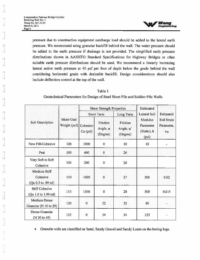
Longmeadow Parkway Bridge CorridorRetaining Wall No. IWang No. 201-23-01 II’angMarch 8,2011 EngineeringPage 6
pressure due to construction equipment surcharge load should be added to the lateral earth
pressure. We recommend using granular backfill behind the wall. The water pressure should
be added to the earth pressure if drainage is not provided. The simplified earth pressure
distributions shown in AASHTO Standard Specifications for Highway Bridges or other
suitable earth pressure distributions should be used. We recommend a linearly increasing
lateral active earth pressure at 40 psf per foot of depth below the grade behind the wall
considering horizontal grade with drainable backfill. Design considerations should also
include deflection control at the top of the wall.
Table 1
Geotechnical Parameters for Design of Steel Sheet Pile and Soldier-Pile Walls
Shear Strength Properties Estimated
Short Term Long Term Lateral Soil Estimated
Moist Unit Modulus Soil StrainSoil Description Friction Friction
Weight (pcf) Cohesion Parameter Parameter,Anale p Angle p’
Cu (psf) (Static), k(Degree) (Degree)
(pci)
New Fill-Cohesive 120 1000 0 30 10 -
Peat 100 400 0 26
Very Soft to Soft105 200 0 26
Cohesive
Medium Stiff
Cohesive 110 1000 0 27 300 0.02
(Qu_0.5_to_.99_tsf)
Stiff Cohesive115 1500 0 28 500 0.015
(Qu_1.0_to_1.99_tsf)
Medium Dense120 0 32 32 60 -
Granular (N 10 to 29)
Dense Granular125 0 34 34 125 -
(N_30_to_49)
• Granular soils are classified as Sand, Sandy Gravel and Sandy Loam on the boring logs.
Longmeadow Parkway Bridge CorridorRetaining Wall No. IWang No. 201-23-01 IWilhlgMarch 8,2011 V” EngineeringPaee 7
• Cohesive soils are classified as Clay, Silty Loam, Silty Clay, and Silty Clay Loam on the
boring logs.
• Unconfined Compressive Strength values of the cohesive soils are shown as Qu on the
boring logs.
• Boring logs show SPT values number for three consecutive 6-inch penetration. N value is
the sum of the total of second and the third numbers.
• Moist unit weight and Friction Angle estimated from SPT numbers.
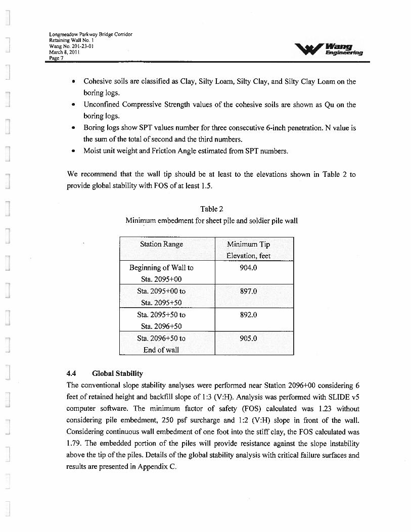
We recommend that the wall tip should be at least to the elevations shown in Table 2 to
provide global stability with FOS of at least 1.5.
Table 2
Minimum embedment for sheet pile and soldier pile wall
Station Range Minimum Tip
Elevation, feet
Beginning of Wall to 904.0
Sta._2095+00
Sta. 2095+00 to 897.0
Sta._2095+50
Sta. 2095+50 to 892.0
Sta._2096+50
Sta. 2096+50 to 905.0
End_of wall
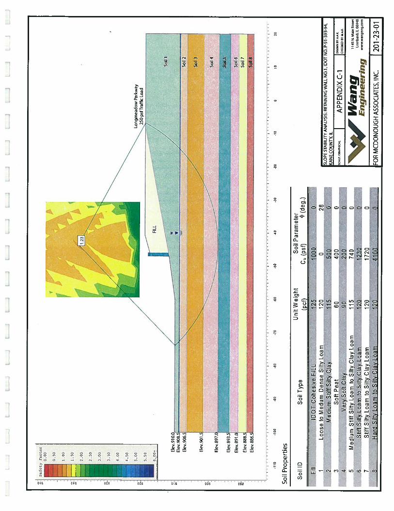
4.4 Global Stability
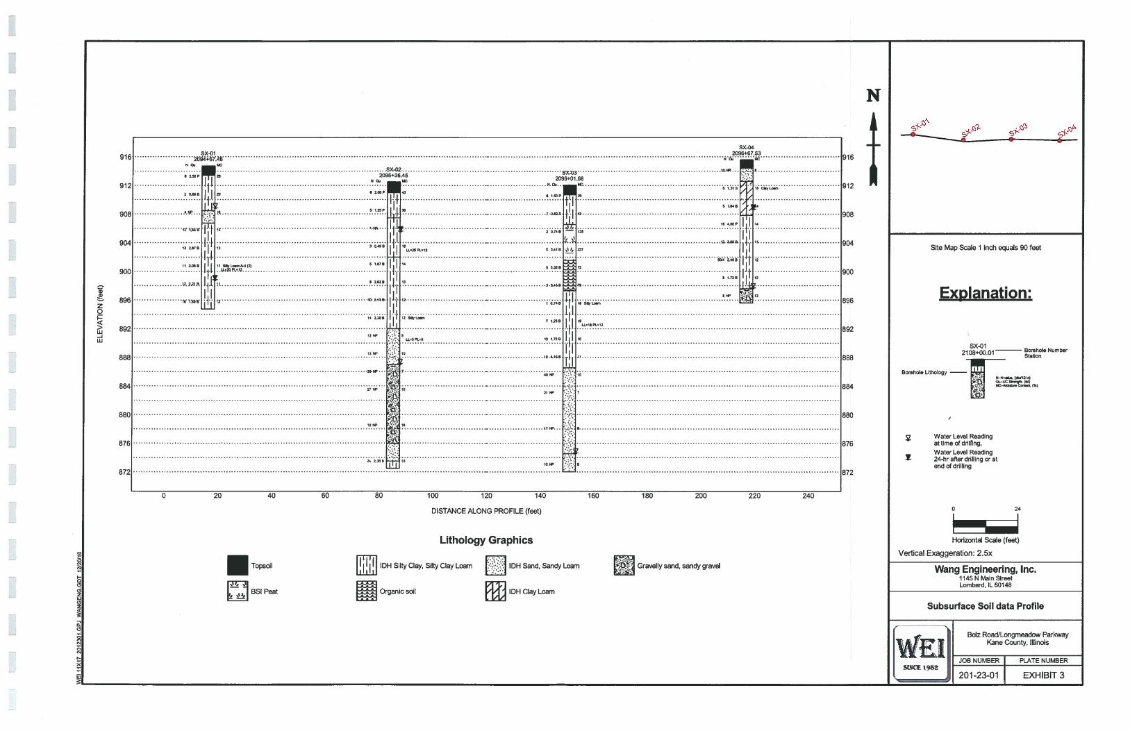
The conventional slope stability analyses were performed near Station 2096+00 considering 6
feet of retained height and backfill slope of 1:3 (V:H). Analysis was performed with SLIDE vS
computer software. The minimum factor of safety (FOS) calculated was 1.23 without
considering pile embedment, 250 psf surcharge and 1:2 (V:H) slope in front of the wall.
Considering continuous wall embedment of one foot into the stiff clay, the FOS calculated was
1.79. The embedded portion of the piles will provide resistance against the slope instability
above the tip of the piles. Details of the global stability analysis with critical failure surfaces and
results are presented in Appendix C.
Longmeadow Parkway Bridge CorridorRetaining Wall No. IWang No. 201-23-01 1$angMarch 8,2011 EngineeringPage 8
4.5 Settlement Analysis
As per cross sections sheet (plot date 10/25/2010) prepared by MA!, it is understood that there
will be a very minor change in the new roadway grade profile near the proposed retaining wall.
The widening of the roadway near the retaining wall will raise the existing grade at Station2096+00 from zero at 10 feet left of centerline to 6 feet at 45 feet left of centerline (at retaining
wall). Wang performed settlement analysis for the widening portion of the roadway. The
estimated maximum settlement of the embankment is on the order of 1.6 inches. The roadway
subgrade treatment will need to be provided to reduce the total settlement. Some downdrag load
may occur on the piles but should be acceptable for the retaining wall.
5.0 CONSTRUCTION CONSIDERATIONS
5.1 Excavation
Any required excavations should be performed in accordance with local, state, and federal
regulations including current OSI-IA regulations. The potential effect of ground movements
upon nearby utilities should also be taken into consideration.
5.2 Dewatering
Based on the results of borings, we do not anticipate any significant groundwater problems
during the construction for an excavation to a depth of 9 feet below exiting roadway
pavement (approximate Elevation 910.0 feet). Perched water existing in the granular
embankment will seep into the excavation in relatively small quantity which can be handled
by the sump pump method. The groundwater is likely to be encountered in excavations below
approximate Elevation 910.0.
5.3 Filling and Backfihling
All fill and backfill materials should be pre-approved by the site engineer. The backfill
material should be porous granular material free of organic materials and debris. Backfill
material should be compacted in lifts no greater than 8 inches in loose thickness. Each layer
should be compacted to a minimum 95 percent of the maximum dry density as determined by
AASHTO T 99, Standard Proctor Method.
5.4 Wall Construction
The wall should be constructed as per IDOT Standard Specifications. The sheet piles could
be installed by driving to the required penetration using a vibratory hammer. The special
Longmeadow Parkway Bridge CorridorRetaining Wall No. IWang No. 201-23-01March 8,2011 W Eng&ieingPage 9
provisions developed by IDOT for construction of steel sheet pile wall and soldier-pile wall,
available at the IDOT web-site (ht p:fl w.dotsateiLusbridesfbstthtmI) should be used. A
temporary casing in granular, and very soft cohesive, organic and peat soils will be required.
5.5 Construction Monitoring
There is no need for a special construction monitoring for the retaining wall except normally
required by the IDOT Standard Specifications.
6.0 QUALIFICATIONS
The analysis and recommendations submitted in this report are based upon the data obtained
from the borings performed by Wang at the locations shown on the boring logs and Exhibit 2.This report does not reflect any variations that may occur between the borings or elsewhere
on the site, variations whose nature and extent may not become evident until the course ofconstruction. In the event that any changes in the design and/or location of the retaining wall
are planned, we should be timely informed so that foundation recommendations can be re
reviewed, and revised if necessary.
It has been a pleasure to assist McDonough Associates, Inc. and Kane County on this project.Please call if there are any questions, or if we can be of further service.
Respectfully Submitted,
WANG ENGINEERING, [NC.
,ç4L
Jerry W.H. Wang, Ph.D., P.E. Mohammed A. Kothawala, P.E., D.GEPrincipal Sr. Project Manager/Sr. Geotechnical Engineer
Longmeadow Parkway Bridge CorridorRetaining Wall No. IWang No. 201-23-01 IVangMarch 8,2011 EngineeringPage 10
REFERENCES
AASHTO 2002. Standard SpecUlcations for Highway Bridges. American Association ofState Highway and Transportation Officials, Inc., Washington, D.C.
IDOT 1999. Geotechnical Manual. Illinois Department of Transportation.
IDOT 2007. Standard Spec,fications for Road and Bridge Construction. Illinois Departmentof Transportation
IDOT 2009. Bridge Manual, Illinpois Department of transportation

S1IHIHXI
5uL,aauJ5u

L_
JL
_-J
LJ
IJ
I
S.
‘1!
LIN
E
i: l/c(1\cd
j4,
J?IIR
d”
11:1
.Ii
92
‘.—
..•
k*.
.,
‘.
c-.
——
—--.
•.•
1I
.4n.
“[o
ngm
eado
w_P
kwy_
_.
IC
__
J.
9O*..\.
.
*,
Ii’._
.)
‘\k)
__
__
__
__
__
R
rC
I,
--
-
1N
/;
...
‘:--.._—
‘-
/
I.“---.
-
,I_—
.1.
.-
______
_S
%_
4?9
’.I
SITE
LOG
•
-
::5.
‘:
•A
,,
4_*-_
7i0
°:-‘
.Tw
er
:7-‘
.?ii
i..,
/_
-,
::>
)/
tIiI.s
I/
-7
.)
TIO
NC
2?k.1
-,i
__L
.1_.
-/i’.))
•)
-\
1.,) -
--I
,j.
ç_.:
k\:
?J
0J1
t-,.
00.
5I
II
1 .0
Mile
KA
NE
CO
UN
TY
SIT
EL
OC
AT
ION
MA
P:R
ET
AIN
ING
WA
LL
NO
.1,
IDO
TN
O.
P-9
1-39
3-94
,K
AN
EC
OU
NT
Y,
IL
3CA
LE:G
RA
PHIC
AL
EX
HIB
IT1
ID
wY
A.
CH
ECK
EDB
YM
.A.
K.
1145
N.
Mai
nS
Iree
IIV
ang
Lom
bard
,IL
60148
Engin
eeri
ng
ww
w.w
ange
ng.c
om
FOR
MC
DO
NO
UG
HA
SSO
CIA
TE
S,IN
C.12
01-2
3-01
BO
RIN
GLO
CA
TIO
NPL
AN
:R
ETA
ININ
GW
ALL
NO
.1
DO
TN
O.
P91
-393
-94,
KA
NE
CO
UN
TY
,IL
‘DR
AW
NBY
:A
.A.K
.0
5010
0F
eet
SCA
LE
:G
RA
PHIC
EX
HIB
IT2—
AI
BY:
M. A
.K.
II’a
i.ig
1145
N.
Mai
nS
tree
tL
omba
rd,
IL60
148
Engin
eeri
ng
ww
w.w
angen
g.c
om
Lon
gm
eado
wPk
wy
FOR
MC
DO
NO
UG
HA
SSO
CIA
TE
S,IN
C.
1201
-23-
01
--
——
——
—
,M
cDon
ough
Ass
oci
ates
Inc.
—I
lao
Lai
tR
anda
tpfl
8.a
Oh
oagI.
0*
-Il
15
.i.
__
__
____
/r
II(4
lb
I 1/
I’
ri
12-0
12’-
O
__
__
_
--
1=
l-
oL
one
Lon
e
+•
[J
II
__
_
I0
lb
I-
rr
-
ci
1i
I1T
e
47
rr9
in:
-I
__
-in
Ii
-no
-i-0
1—0
-I_
0
CIb
OCO
0
00
H
V1
1JJ
H,
C)0G
)—
Ii
z19
•____ H
üüHs12
I!‘m
Ib
Cb
-a
-•0
-C
)-
Eiev
.92
0.04
-
FINA
L
a,a)z0
>w-J‘JJ
916
912
908
904
900
896
892
888
884
880
876
872
----
SX-04SX-O1 2096+67.53
N .01
SX-02 10.11’ 1,2. 8
I .[2095+36.45
2O96+08 ....I 6 1.31S A 16
068 h.P. 20 .. .‘..‘:°.
‘
Ii 51.64B ‘j’ 14S 1.25P 364.71’ .,. - 7.0.825 ... 43
[], ....
. !.I.I 5 I
1.-I 12.3.688. f. 15.
13 2.878P , 3 0.49 B I :1
16PL13 0 0.41 B 237 I I
50142.466 12
11208 IL LJ.414.Y •I.. .
I I 81.728 12
t2.3.2.SA it 3.0141.8 :
1:80Wiii 50.2.186. 1.6 ....
10 2.388 12 SlByLo8rn7 1.236 9
U
LLL18P112
1211’ ::: 0I
U.0 Pt=0 10 1.728 10
1311’ ::: sot.._ 48.4.568 .. II
3341’ 7 •.
49 81’ .: 10
.:•
27P 1650, 2111’ ...7
...:?1851’ 50 —
24 2.388 50
L_J :-
N
916
912
908
904
900
896
892
888
884
880
876
872
Site Map Scale 1 inch equals 90 feet
ExDlanation:
0 20 40 60 80 100 120 140
DISTANCE ALONG PROFILE (feet)
Lithology Graphics
160 180 200 220 240
IDH Silty Clay, Silty Clay Loam IDH Sand, Sandy Loam Gravelly sand, sandy gravel
BSI Peat Organic soil IDH Clay Loam
Sx-01
_______
21 08+00.01 Borehole Number
Borehole Lithology41 i.5 •5—50380o. 50.4125)
00-201 S0og8. 181)—M509,re CoBr5 (50)
Water Level Readingat time of drilling.Water Level Reading24-hr after drilling or atend of drilling
0 24
Horizontal Scale (feet)
Vertical Exaggeration: 2.5x
Wang Engineering, Inc.1145 N Main StreetLombard, IL 60148
Subsurface Soil data Profile
[Wi.)(j 12
—
Bolz RoadiLongmeadow ParkwayKane County, Illinois
JOB NUMBER PLATE NUMBER
201-23-01 EXHIBIT 3
F
‘%‘Wang‘ Engineering
rErrr:
tAPPENDIX A
LE
LL
Page 1 of 1
wang BORING LOG SX-O1Evg,neer,ng
Datum [email protected] WEI Job No.: 2012301 Elevation: 914.74 ft1145 N Main Street Client McDonough Associate Inc North: 1993450.03 ft
Lombard IL 60148 East: 987251.45 ft
Telephone: 630 953-9928Project BoIz RoadLongm w ParKway Station: 2094+67.46
Fax: 630 953-9938 Location ne.C.°unty,.H!inois Offset: 46.16 LT
a)
0a-
Ca
(1)
16-inch thick, black and brownSILTY CLAY LOAM
D
o
C-)
a)0
a-
a)a. C
.
SOIL AND ROCK— a.
DESCRIPTION(I)
1
2
CC
auJ
--TOPSOIL--
SOIL AND ROCKDESCRIPTION
Medium stiff to very stiff, black,brown and gray SILTY CLAY,trace gravel
--FILL--
5
Ofl7
Stiff toSILTY LOAM to SILTY CLAYLOAM
10
233
211
022
266
567
356
357
3.50P
0.66B
NP
1.64B
2.87B
2.05B
2.21B
1.89B
26
20
16
15
13
11
11
12
3
4
5
6
7
8
--LL(%)=20, PL(%)=12—%Gravel9.2--%Sand=26.7--lt
--%Silt=52.5----%Clay=11.5--
Thin sand lense at 14.75 bgs
terminated at 20.00 ft
479
25
C:
C
C
C-2C)2CLC:2Ca
GENERAL NOTES WATER LEVEL DATABegin Drilling -09-2 Complete Drilling -0.9-20 While Drilling .Q0. ftDrilling Contractor WTS Drill Rig ... TMR B-57 At Completion of Drilling Y .00. ftDriller R&J Logger C.. Pavis Checked by A. Ku ia Time After Drilling NADrilling Method
. .3,2-jnc.h. .HSA Depth to Water NAThe stratification lines represent the approximate boundary
between
soil Woes: the actual transition may be gradual.
Soft, gray SILTY CLAY withtrace SAND
--LL(%)=25, PL(%)=13--
0.25-inch gray sand seam at12.75 feet
--%Gravel=12.3----%Sand24.
GENERAL NOTESBegin Drilling 11-08-2010 Complete Drilling 11-09-2010Drilling Contractor WTS Drill Rig ...TMR B.5Driller R& Logger N. Boddy Checked by A. KurniaDrilling Method
. .3.25-inch .HSA
Boring terminated at 40.00 ft
WATER LEVEL DATAWhile Drilling 25.50 ftAt Completion of Drilling Y 7..0.0.ftTime After Drilling NADepth to Water NAThe stratification lines represent the approximate boundary
Page 1 of 1
VrWang BORING LOG SX-02Eng,eeriag
Datum NGVD
wangengwangeng.com WEI Job No.: 20 1-23-01 Elevation: 912.48 ft1145 N Main Street Client McPqugi.Asoci.ate Inc Norlh: 1993442.25 ft
Lombard IL 60148 East: 987320.19 ft
Telephone: 630 953-9928Project BoIz Rq? gmeadpw arkway Station: 2095+36.45
Fax: 630 953-9938 Location e.cpunty,.!!!inpjs Offset: 41.10 LT
a)
0
0
C0
a)UI
SOIL AND ROCKDESCRIPTION 0
a)0.>,
0.
CDCl)
dza)0.ECD
Cl)
U,
CD co>
Cl)
SOIL AND ROCKDESCRIPTION
SANDY GRAVEL

- 37.5O
At Completion of Drilling DRYTime After Drilling NA
While Drilling
Page 1 of 1
‘%Wang BORING LOG SX-03VV Engrneerrng
Datum NGVD
wangengwangeng.com WEI Job No.: 201-23-01 Elevation: 912.04 ft
1145 N Main Street Client MCDOn°ugh Associates, Inc North: 1993443.25 ft
BoI’ Longmeadow ?.rkway Station; 2096+0t68
Fax: 630 953-9938 Location Kane County, Illinois Offset: 44.67 LT
‘1)
0
0,
C0
>.—a)
UI
SOIL AND ROCKDESCRIPTION
0>,
0.
.0
0.0
az0,E(‘3
U,
Cl)
‘3 (C
>-
LI)
16-inch thick TOPSOIL--TOPSOIL--
ium suit to stiff, black atbrown organic SILTY CLAY
SOIL AND ROCKDESCRIPTION
Medium dense to dense, graySANDY LOAM with trace gravel
--%GraveI5.3----%Sand=20.2--
--%Silt=64.8----%C1ay9.7--
--LL(%)=18, PL(%)=12--
GENERALBegin Drilling -08-2Drilling Contractor WTS
Complete Drilling -08-2Drill Rig ....TMR.-B-
Driller Logger N..Boddy Checked by A. KurnjaDrilling Method .3.25-inch. .HSA

Page lot 1
wany BORING LOG SX-04Eng,neer,ng
Datum: NGVDwangengwangeng.com WEI Job No.: 2012301 Elevation: 915.59 ft1145 N Main Street Client McDonough Associates, Inc North: 1993441.22 ft
T&ephone 630Project BoIz. Rqpngmcadv..p.cway Stabon:2096+6T53
Fax: 630 953-9938 Location e.çqity,.H!inojs Offset: 45.23 LT
Ca) aSOIL AND ROCK
DESCRIPTION 0
a)a)
a). ‘-
a)(I,
aza)a)Sa)
U,
CD
>
Cl)
D
Ua)a0
14-ich thick, black SILTY CLAY
--TOPSOIL--f
Medium dense, brown SANDYLOAM
912.6
. SOILAND ROCKDESCRIPTION t
0)a).>,,I—
a). ‘
ESa)U,
aza)a)Sa)(i
0l
CD
>-
U,
DO:g o-
(2
Stiff, black, brown and grayCLAY LOAM
--FILL---%GraveIO.2-- Q—%Sand=44.0--
--%SiIt=31.1-- ---%Clay=24.6--
907.8
Stiff to hard, brown and grayI I SILTY LOAM to SILTY CLAY
LOAM, trace gravel
III 10
15
jJ• 897.6
2
3
4
5
6
7
8
564
333
223
499
457
36
50/4
335
335
NP
1.31S
1.64B
4.00P
369B
2.46B
1.72B
NP
8
16
24
14
11
12
12
13
x
x
x
xLoose, brown GRAVELLYSAND
895.6 20Boring terminated at 20.00 ft
25
0(2
0“C
0N
C)z(32a)(32
2
GENERAL NOTES WATER LEVEL DATABegin Drilling -08-2 Complete Drilling 082 While Drilling 8.00 ftDrilling Contractor WTS Drill Rig ... TMR B5 At Completion of Drilling Y 7.00. ftDriller R& Logger Boddy Checked by A Time After Drilling NADrilling Method .3..2-i.n.c.h. .HSA Depth to Water N.A
The stratification lines represent the approximate boundary
between
soil types: the actual transition may be gradual.
3546
4799
3335
2444
Page 1 of 1Wang BORING LOG R-033Engineering
Datum NGVD
[email protected] WEI Job No.: 201 23O1 Elevation: 914.97 ft
1145 N Main Street Client McDonouhPssocjate North: 1993426.60 ft
Lombard, IL 60148 East: 987383.31 ftProject BoIz Road . +
Telephone: 630 953-9928 tation.
Fax: 630 953-9938 Location çunty, IlJmois Offset: 27.94 L
SOIL AND ROCKDESCRIPTION
)14.0 —TOPSOIL—
Loose to medium dense, blackSILTY LOAM
j g SOILAND ROCKz DESCRIPTION .
0 tOU) C.)
13
312
5 3
i’ll
37
4
ark brown PEAT
904.0
5
10
3233
Very soft to medium stiff, graySILTY CLAY LOAM
NP
NP
NP
0.20P
NP
0.50P
0.00P
0.00P
0.00P
1.25P
6 111
1000
7
68
239
86
53
65
34
17
158
9
1000
000
246
10
25
GENERAL NOTIBegin Drilling 6-06-2 - Complete Drilling -06-2005Drilling Contractor PcQN.P.R!WNG Drill Rig CME55TMRDriller K Logger Koslosk Checked by . B.. Fugiel.Drilling Method ,25-inch. H.SA
WATER LEVEL DATAWhile Drilling PRYAt Completion of Drilling Y PRYTime After Drilling NADepth to Water NAThe stratification lines represent the approximate boundaryhotween coil twinc the ertrrI trencitinn mev ho nrcrlrrai
*‘Wang -
Engineering
APPENDIX B

PLAS
ITY
NDEx
60
/5C
74C 7/
3C_____ 7/__V
2C
7
17zic
CL-ML *
02 ) 40 60
LIQUID LIMIT
80 I U0
Specimen Identification LL PL P1 Fines IDH Classification
• SX-01#6 13.5 ft 20 12 8 64 Silty Loam
X SX-02#4 8.5ff 25 13 12
A SX-02#9 21.0 ft NP NP NP
* SX-03#8 18.5ft 18 12 6
fl1 Wang Engineenng Inc - ATTERBERG LIMITS’ RESULTS
I rLfl6SOt Project BoIz Road/Longmeadow Parkway
Telephone: 630 953-9928 Location: Kane County, IllinoisFax: 630 953-9938

U.S. SIEVE OPENING IN INCHES U.S. SIEVE NUMBERS HYDROMETER
I
CDw
>-
wzL1
IzwC-)
LU0
SAND ICOBBLES GRAVEL I SILTAND CLAY
coarse fine
GRAIN SIZE IN MILLIMETERS
CC
Specimen Identification IDH Classification LL PL P1 Cc Cu• SX-01#6 13.5 ft Silty Loam 20 12 8I SX-02#8 18.5 ft Silty Loam 0.61 2467A SX-03#7 16.0 ft Silty Loam 0.40 19.77* SX-04#2 3.5 ft Clay Loam
Specimen Identification D100 D60 D30 D10 %Gravel %Sand %SiItJ/oCIay• SX-01#6 13.5ft 12.7 0.064 0.01 9.2 26.7 52.5 11.5Z SX-02#8 18.5ft 12.7 0.068 0.011 0.003 12.3 24.5 55.0 8.3
SX-03#7 16.Oft 12.7 0.042 0.006 0.002 5.3 20.2 64.8 9.7* SX-04#2 3.5ft 4.75 0.139 0.003 0.2 44.0 31.1 24.6
GRAIN SIZE DISTRIBUTION
W
Wang Engineering Inc. 1 145 N Main Street Project: BoIz Road/Longmeadow Parkway
SCEFax: 630 953-9938
, / Lombard, 1L60148Telephone: 630 953-9928 Location: Kane County, Illinois
— Number: 201-23-01
WrWang -
Engineering
APPENDIX C
L-_
-JL
_J
L_
JL
_J
.-.-
.JL-
-.-_J
L...
.,:J
Li
Sot
i5
Soil
6
Soil
7
Soi
i8
-i-—
.v
.rrrr-
i—1—
-j---—
1—ri—
rT-cv
f:
-110
-100
-90
-80
-70
-60
-60
-40
-30
-20
-It
010
20
Soil
Pro
pert
ies
Uni
tW
eigh
tSo
ilP
aram
eter
Soil
IDSo
ilT
ype
(pcf
)C
(psf
)(d
eg.)
Fill
DO
TC
ohes
ive
FILL
125
1000
0I
Loo
seto
Med
umD
ense
Silty
Loa
m--
120
--
.0-
282
Med
ium
Stif
fSi
ltyC
lay
115
500
03
Soft
Pea
t60
400
04
Ver
ySo
ftC
lay
--
90-
200
-
5M
ediu
mSt
iffSi
ltyL
oam
toSi
ltyC
lay
Loa
m11
5-
740
06
Stif
fSi
ltyL
oam
toSi
ltyC
lay
Loa
m12
0-
.12
30.
0-
--
7-
Stiff
Silty
Loa
mto
Silty
Cla
yL
oam
120
1720
--
-0
-
8-
Har
dSi
ltyL
oam
toSi
ltyC
lay
Loa
m-
120
--
:41
00.
-0
SLO
PEST
ABI
LITY
AN
ALY
SIS:
RETA
ININ
GW
ALL
NO
.1,
IDO
TN
O.P
-91
-393
-94,
KA
NE
COU
NTY
,IL
SCA
LE:G
RAPH
ICA
LA
PPEN
DIX
C—i
I DRA
WN
85.
CHEC
KED
BY:M
A.K.
1145
N.
Mai
nS
tree
t14
’ang
jL
om
bar
d,
IL60148
En
gin
eeri
ng
ww
w.w
ang
eng
.co
m
FOR
MC
DO
NO
UG
HA
SSO
CIA
TES,
INC.
201-
23-0
1
Safe
tyF
acto
r-
0.0
0
0.
50
1-00
1.5
0
2-
00
2.5
0
3-
00
3.
50
4-
00
‘l-
50
5.0
0
5.5
0
6.
00+ EI
ev.9
10.0
EIev
.908
.5EI
ev.9
06.5
EIev
.901
.5
EIev
.897.
Eiev
.893
.51
Eiev
.891
.C
Eiev
.888
.’C
I..,,
oO
—12
3
IL
L
Lon
gmea
dow
Park
way
psfT
raff
’icL
oad
/So
il1
--
.--z ..
-
-
Z:-
V

Safe
tyF
acto
r0.0
0
0.
50
LO
S
1.5
0
.12.0
0
2.5
0
3.
00
3.5
0
4.0
0
4.
50
5.0
0
5.5
0
0.0
0+
-110
Soil
Pro
pert
ies
Uni
tW
eigh
tSo
ilP
aram
eter
Soil
IDSo
ilT
ype
(pcf
)C0
(psf
)I
(deg
.)
Fill
DO
TC
ohes
ive
FILL
125
1000
01
Loo
seto
Med
umD
ense
Silty
Loa
m12
00
282
Med
ium
Stiff
Silty
Cla
y11
550
00
3So
ftP
eat
6040
00
4V
ery
Soft
Cla
y90
200
05
Med
ium
Stiff
Silty
Loa
mto
Silty
Cla
yL
oam
115
740
06
Stiff
Silty
Loa
mto
Silty
Cla
yL
oam
120
1230
.0
7St
iffSi
ltyL
oam
toSi
ltyC
lay
Loa
m12
017
200
8H
ard
Silty
Loa
mto
Silty
Cla
yL
oam
120
4100
0
SLO
PEST
ABI
LITY
AN
ALY
SIS:
RETA
ININ
GW
ALL
NO
.1,
IDO
TN
O. P
-91
-393
-94,
KA
NE
COU
NTY
,IL
SCAL
E:G
RAPH
ICA
LA
PPEN
DIX
C—2
DRAW
NBY
.A,A
.K.
CHEC
KED
BY:M
AIl
.
1145
N.
Mai
nS
tree
t14’a
’gL
om
bar
d,
IL60148
En
gin
eeri
ng
ww
w.w
ang
eng
.co
m
Lon
ymea
dow
Park
way
250
psf T
raff
icL
oad
-100
-90
-80
-70
-60
50-4
0-3
0.2
0-1
00
1020
FOR
MC
DO
NO
UG
HA
SSO
CIA
TES,
INC.
201-2
3-0
1