Embed Size (px)
Citation preview

DOE/AL/62350-235
REV. 1
LONG-TERM SURVEILLANCE PLANFOR THE
ESTES GULCH DISPOSAL SITE NEAR RIFLE, COLORADO
November 1997
DOE and DOE contractors can obtain copies of thisreport from:
Office of Scientific and Technical InformationP.O. Box 62Oak Ridge, TN 37831(615) 576-8401
This report is publicly availablefrom:
National Technical InformationServiceDepartment of Commerce5285 Port Royal RoadSpringfield, VA 22161(703) 487-4650
Long-Term Surveillance Plan for the Estes Gulch Disposal Site Near Rifle... http://lts1.lm.doe.gov/documents/rfl/ltsp.html
1 of 25 5/20/2009 1:38 PM
Prepared for
U.S. Department of EnergyEnvironmental Restoration Division
UMTRA Project TeamAlbuquerque, New Mexico
Prepared by
Jacobs Engineering Group Inc.Albuquerque, New Mexico
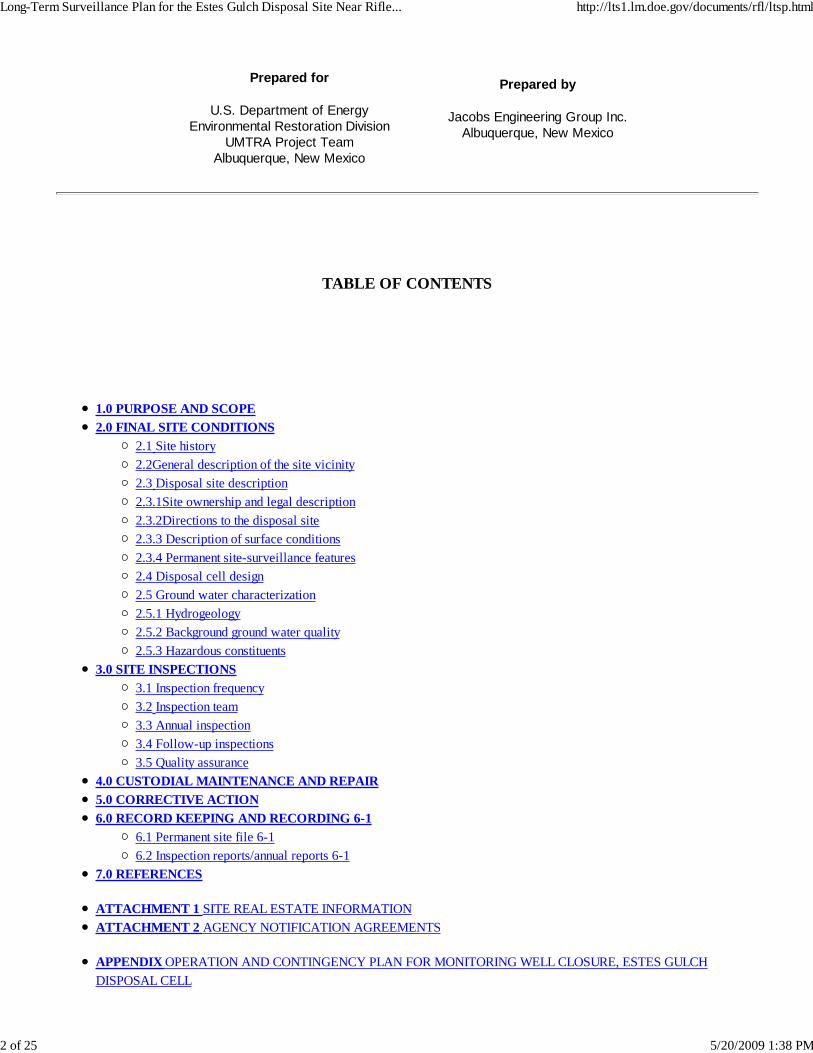
TABLE OF CONTENTS
1.0 PURPOSE AND SCOPE2.0 FINAL SITE CONDITIONS
2.1 Site history2.2General description of the site vicinity2.3 Disposal site description2.3.1Site ownership and legal description2.3.2Directions to the disposal site2.3.3 Description of surface conditions2.3.4 Permanent site-surveillance features2.4 Disposal cell design2.5 Ground water characterization2.5.1 Hydrogeology2.5.2 Background ground water quality2.5.3 Hazardous constituents
3.0 SITE INSPECTIONS3.1 Inspection frequency3.2 Inspection team3.3 Annual inspection3.4 Follow-up inspections3.5 Quality assurance
4.0 CUSTODIAL MAINTENANCE AND REPAIR5.0 CORRECTIVE ACTION6.0 RECORD KEEPING AND RECORDING 6-1
6.1 Permanent site file 6-16.2 Inspection reports/annual reports 6-1
7.0 REFERENCES
ATTACHMENT 1 SITE REAL ESTATE INFORMATIONATTACHMENT 2 AGENCY NOTIFICATION AGREEMENTS
APPENDIX OPERATION AND CONTINGENCY PLAN FOR MONITORING WELL CLOSURE, ESTES GULCHDISPOSAL CELL
Long-Term Surveillance Plan for the Estes Gulch Disposal Site Near Rifle... http://lts1.lm.doe.gov/documents/rfl/ltsp.html
2 of 25 5/20/2009 1:38 PM

LIST OF FIGURES
Figure 2.1 Location of the Estes Gulch disposal site near Rifle, ColoradoFigrue 2.2 Estes Gulch disposal site near Rifle, ColoradoFigure 2.3 Cover cross section typical thickness Estes Gulch disposal site near Rifle, ColoradoFigure 2.4 Geologic cross sections, Estes Gulch disposal site near Rifle, ColoradoFigure 2.5 Monitor well locations, Estes Gulch disposal site near Rifle, ColoradoFigure 3.1 Steps for follow-up inspections, custodial maintenance, and corrective action, at the Estes Gulch disposal site nearRifle, Colorado
LIST OF PLATES
Plate 1 Disposal site baseline map, Rifle, Colorado, site (To be added when complete.)
LIST OF TABLES
Table 2.1 Locations of permanent surveillance features, Rifle, Colorado, disposal siteTable 2.2 Completion intervals and ground water levels in monitor wells,Estes Gulch site near Rifle, ColoradoTable 2.3 Summary of background water quality at the Estes Gulch disposal site near Rifle, Colorado
LIST OF ACRONYMS
Acronym
BLMDOEEISEPAHDPELTSPMCLMK-FNGVDNRCPOCQARAPTACTDSUMTRAUMTRCA
Definition
Bureau of Land ManagementU.S. Department of Energyenvironmental impact statementU.S. Environmental Protection Agencyhigh density polyethylenelong-term surveillance planmaximum concentration limitMorrison Knudsen-FergusonNational Geodetic Vertical DatumU.S. Nuclear Regulatory Commissionpoint of compliancequality assuranceremedial action planTechnical Assistance Contractortotal dissolved solidsUranium Mill Tailings Remedial ActionUranium Mill Tailings Radiation Control Act
Long-Term Surveillance Plan for the Estes Gulch Disposal Site Near Rifle... http://lts1.lm.doe.gov/documents/rfl/ltsp.html
3 of 25 5/20/2009 1:38 PM

1. 0 PURPOSE AND SCOPE
This long-term surveillance plan (LTSP) describes the U.S. Department of Energy’s (DOE) long-term careprogram for the Uranium Mill Tailings Remedial Action (UMTRA) Project Estes Gulch disposal site locatednear Rifle, Colorado, in Garfield County.
The U.S. Nuclear Regulatory Commission (NRC) has developed regulations for the issuance of a generallicense for the custody and long-term care of UMTRA Project disposal sites in 10 CFR Part 40. Thepurpose of this general license is to ensure that the UMTRA Project disposal sites are cared for in amanner that protects the public health and safety and the environment. For disposal sites to be licensed,the NRC requires the DOE to submit a site-specific LTSP; the DOE prepared this LTSP to meet thatrequirement for the Estes Gulch disposal site. The general license becomes effective when the NRCconcurs with the DOE’s determination of completion of remedial action for the Estes Gulch site and theNRC formally accepts this LTSP.
This document describes the long-term surveillance program the DOE will implement to ensure that theEstes Gulch disposal site performs as designed. The program is based on site inspections to identifythreats to disposal cell integrity. The LTSP is based on the UMTRA Project long-term surveillance programguidance (DOE, 1996a) and meets the requirements of 10 CFR §40.27(b) and 40 CFR §192.03.
2. 0 FINAL SITE CONDITIONS
Remedial action at the former uranium processing sites in Rifle, Colorado, consisted of excavating andrelocating the residual radioactive materials to the Estes Gulch disposal site. The DOE constructed adisposal cell to control the residual radioactive materials in accordance with 40 CFR Part 192. The EstesGulch disposal site is partially fenced, and its perimeter is marked with warning signs. The site completionreport (DOE, 1997) contains a detailed description of the final site conditions.
2.1 SITE HISTORY
The Estes Gulch disposal cell was constructed to stabilize waste from the two former processing sitesnear Rifle, Colorado. Both processing sites (named Old Rifle and New Rifle) are located on the floodplainof the Colorado River valley and are north of the Colorado River. Old Rifle is just east of the city limits ofRifle, in Garfield County, Colorado. New Rifle is west of the city of Rifle, approximately 2 miles (mi) (3kilometers [km]) from Old Rifle. The Estes Gulch disposal cell is located approximately 6 mi (9 km) north ofRifle.
Both processing sites were once owned by Union Carbide Corporation, but now are owned by the state ofColorado. The Old Rifle plant was built by the Standard Chemical Company in 1924 and in 1928 wasbought by the United States Vanadium Corporation (an eventual subsidiary of the Union CarbideCorporation). The mill operated from 1924 to 1932, and again from 1942 to 1946 for recovery ofvanadium. In 1946, uranium processing was added to the vanadium recovery circuit and recovery of bothvanadium and uranium continued until 1958. In 1958, operations were transferred to the New Rifle mill andthe Old Rifle mill was shut down.
About 761,000 short tons (tons) of ore from the nearby Meeker and Rifle Creek mines, as well as ore from
Long-Term Surveillance Plan for the Estes Gulch Disposal Site Near Rifle... http://lts1.lm.doe.gov/documents/rfl/ltsp.html
4 of 25 5/20/2009 1:38 PM

the Uravan mineral belt, were processed at the Old Rifle mill. Tailings and spent processing solutions weredeposited at the site. About 411,000 tons of these tailings were later reprocessed at the New Rifle mill anddeposited there. Approximately 350,000 tons of tailings (approximately 259,000 cubic yards [yd3], or197,000 cubic meters [m3]) remained at Old Rifle. In 1967, Union Carbide moved the southern edge of thistailings pile away from the Colorado River and partially stabilized the pile with a 6-inch (15-centimeter [cm])cover of earth seeded with grasses.
In July 1958, operations began at the New Rifle mill, which produced both uranium and vanadium untilDecember 1972. After 1972, only vanadium was produced and milling operations ceased in 1981. Inaddition to tailings from the Old Rifle site, uranium ores and upgrader products were processed at the NewRifle mill. A total of 2.7 million tons of tailings, ores, and upgrader products were processed at this mill.
Upgrader products came from other Union Carbide mills at Slick Rock, Colorado, and Green River, Utah.Upgrader products from Slick Rock were dried fines, dried slime concentrates, green sludge, and uranium-bearing chemical precipitates. The Green River upgrader products consisted of dried slimes and asphalticuranium-bearing concentrates. Uranium bearing lignite ash from Belfield, North Dakota, was supplied to theNew Rifle mill. Union Carbide partially stabilized the New Rifle pile with mulch, fertilizer, and native grasses.
At the Old Rifle mill, a salt roasting process initially was used to recover vanadium. Water, sodium chloride,and sulfuric acid were used in this process. When uranium processing was added to the vanadiumrecovery circuit in 1946, additional reagents were used: hydrochloric acid, sodium hypochlorate, sodiumcarbonate, ferric iron sulfate, ammonia, and ammonium chloride.
The New Rifle mill used a solvent extraction method to recover uranium. Reagents used in the processincluded water, sodium chloride, sulfuric and hydrochloric acid, kerosene, di(2-ethylhexyl) phosphoric acid,sodium hypochlorate, sodium carbonate, sodium hydroxide, and ammonia.
The Uranium Mill Tailings Radiation Control Act (UMTRCA) of 1978 (42 USC §7901 et seq.) gave the DOEauthority to perform remedial action at both Rifle sites. The DOE evaluated the environmental impactsassociated with site remedial action in an environmental impact statement (EIS) (DOE, 1990. The NRC andthe state of Colorado concurred with the DOE's remedial action plan (RAP) (DOE, 1992a) to comply withthe requirements of 40 CFR Part 192, Subparts A through C.
The DOE began constructing the Estes Gulch disposal cell in 1993. During 1994 and 1995, the DOErelocated uranium mill tailings and other residual radioactive materials (such as contaminated mill buildingsand associated debris, windblown materials, and about 24,000 yd3 [18,400 m3] of vicinity propertymaterials) and placed them in the Estes Gulch disposal cell. Disposal cell construction was completed in1996 with placement of a radon/infiltration barrier and frost- and erosion-protection layers. A completionreport documents compliance with the RAP and the site as-built conditions (DOE, 1997). In addition, theDOE prepared a final audit report and certification summary and submitted it along with the completionreport to the NRC for concurrence. Concurrence from the NRC on the completion report is included in thepermanent site file.
2.2 GENERAL DESCRIPTION OF THE SITE VICINITY
The Estes Gulch disposal site is in Garfield County in west-central Colorado on the western slope of theRocky Mountains. The site is approximately 6 mi (10 km) north of the town of Rifle, Colorado (Figure 2.1)in Township 5 South, Range 93 west, Section 14. This section briefly describes the site vicinity. Detaileddescriptions can be found in the site EIS (DOE, 1990) and the RAP (DOE, 1992a).
Figure 2.1 Location of the Estes Gulch disposal site near Rifle, Colorado
The general climatic regime in the vicinity of the Estes Gulch disposal site is semiarid. North of Estes Gulchat significantly higher elevations, precipitation is much heavier. The area is characterized by low humidity,frequent sunny days, and large diurnal and seasonal temperature ranges. The average annual precipitationin the region is 11 inches (28) centimeters [cm]) and the average temperatures range from 23 to 71
Long-Term Surveillance Plan for the Estes Gulch Disposal Site Near Rifle... http://lts1.lm.doe.gov/documents/rfl/ltsp.html
5 of 25 5/20/2009 1:38 PM

degrees Fahrenheit (° F) (-5 to 22 degrees Celsius [° C]) (Yeend, 1969). Snowfall averages 37 inches (94cm) a year. The highest monthly rainfall usually occurs during July and August, while the least rainfalloccurs from April through June. Summer rainfall occurs as intense, scattered thunderstorms.
Site-specific precipitation, temperature, and wind-related data were collected from October 1993 toSeptember 1996. Average annual precipitation ranged from about 14.3 to 18.5 inches (36 to 47 cm).Annual snowfall ranged from 22.3 to 34 inches (57 to 86 cm). The site-specific average daily temperatureranged from 15 to 86° F ( - 9.4 to 30° C).
Site-specific wind data indicate that wind direction was predominately from the west and northwest over 50percent of the period of record. Winds were from the south 10 percent of the time. Wind intensity data areavailable from Morrison Knudsen-Ferguson (MK-F) (MK-F, 1996).
The Estes Gulch site ranges from about 5960 to 6200 feet (ft) (1820 to 1890 meters [m]) above mean sealevel. The Grand Hogback rises to an elevation of about 7850 ft (2400 m) north of the site. To the south,3300 ft (1000 m) the dissected pediment surfaces drop down to the alluvial valley of Government Creek atan elevation of about 5750 ft (1750 m).
The Estes Gulch site is at the head of a small drainage basin on a dissected pediment and alluvial fansurface sloping southwest toward Government Creek from the foot of the Grand Hogback monocline.
Off-site runoff water that could have affected the integrity of the cell previously came from a 20-acre (ac)(8-hectare [ha]) watershed north of the cell. Runoff from about 6 ac (2 ha) of the uppermost part of thiswatershed was diverted from the disposal cell by an interceptor ditch. The other 14 ac ( 5.6 ha) of thewatershed between the interceptor ditch and the cell were graded and covered with erosion-resistantmaterial. The graded area has a slight crown to shed some runoff away from the cell and onto the adjacentground. Precipitation falling on top of the cell will drain to a toe ditch at the south end and will dischargeeastward into Estes Gulch (DOE, 1992a).
There is little potential for future natural resource development in the immediate site vicinity.
2.3 DISPOSAL SITE DESCRIPTION
This section briefly describes the disposal site; detailed descriptions can be found in the site RAP (DOE,1992a) and completion report (DOE, 1997).
2.3.1 Site ownership and legal description
The government currently owns the Estes Gulch disposal site and most of the surrounding area. TheBureau of Land Management (BLM) permanently transferred administration of public land to theDOE in August 1991 for use as the Estes Gulch disposal site. The BLM administers the adjacentsurrounding lands. Attachment 1 provides a legal description of the disposal site. Plate 1 shows thefinal site boundary and identifies ownership of the site and surrounding areas at the time oflicensing.
2.3.2 Directions to the disposal site
The Estes Gulch disposal site can be reached by automobile via paved and gravel roads (Figure2.2) by following these directions.
From Rifle, Colorado, at the intersection of U.S. Highway 6 (also called U.S. Highway 24) and theState Highway 13 by-pass, go north.
1.
Take the State Highway 13 bypass to State Highway 13 north; go approximately 5 mi (8 km).2.Turn right onto a paved road. The paved section of the road extends about 30 ft (9 m) to a gate.After the gate, the road becomes a gravel road. Follow this gravel road about a mile to the disposalsite.
3.
Long-Term Surveillance Plan for the Estes Gulch Disposal Site Near Rifle... http://lts1.lm.doe.gov/documents/rfl/ltsp.html
6 of 25 5/20/2009 1:38 PM

Entry to the disposal site is restricted by a fence at the site entrance. The south access gate is keptlocked and the key needed to enter the site may be obtained from the DOE Grand Junction Office.
4.
2.3.3 Description of surface conditions
The Estes Gulch disposal site is located on approximately 205 ac (83 ha) (Plate 1). The completionreport contains a detailed description of the final site conditions, including the results of the final sitetopographic survey.
During the final site grading, all areas were contoured to promote drainage away from the disposalcell. A mix of grasses and sagebrush was used to revegetate all disturbed areas of the disposal sitenot covered by riprap (DOE, 1997).
At the completion of remedial action, the DOE documented final disposal site conditions with sitemaps, as-built drawings, and ground and aerial photographs.
Figure 2.2 Estes Gulch Disposal site near Rifle, Colorado
2.3.4 Permanent site-surveillance features
Survey and boundary monuments, site markers, and warning signs are thepermanent long-term surveillance features of the Estes Gulch disposal site.Plate 1 shows the locations of these features and Table 2.1 provides surveycoordinates for the monuments and markers. Typical construction andinstallation specifications for these features are shown in the long-termsurveillance guidance (DOE, 1996a) and subcontract documents (DOE,1996b).
Table 2.1 Locations of permanent surveillance features, Rifle, Colorado, disposal site
Feature Location coordinatesa
Survey monuments
SM-1 N 56,000 E 53,400
SM-2 N 56,500 E 52,100
SM-3 N 59,600 E 52,600
Site markers
SMK-1 N 56,000 E 53,550
SMK-2 N 57,200 E 52,550
Long-Term Surveillance Plan for the Estes Gulch Disposal Site Near Rifle... http://lts1.lm.doe.gov/documents/rfl/ltsp.html
7 of 25 5/20/2009 1:38 PM

Boundary monuments
BM-1 N 55,900 E 54,270
BM-2 N 57,205 E 54,280
BM-3 N 57,220 E 53,655
BM-4 N 59,140 E 53,680
BM-5 N 59,170 E 54,000
BM-6 N 60,070 E 53,985
BM-7 N 60,080 E 53,360
BM-8 (No monument.)
BM-9 (No monument.)
BM-10 N 59,245 E 52,350
BM-11 N 59,250 E 52,050
BM-12 N 58,945 E 52,045
BM-13 (No monument.)
BM-14 N 58,250 E 51,690
BM-15 N 58,250 E 51,385
BM-16 N 57,270 E 51,360
BM-17 (No monument.)
BM-18 N 56,645 E 51,185
BM-19 N 56,620 E 52,010
BM-20 (No monument.)
aCoordinates in feet based on Project Survey Control Points: CP-13, N 58,634.94, E54,353.21; CP-15, N 59,208.41, E 52,222.98; CP-19, N 59,856.50, E 53,526.86.
Three survey monuments establish permanent horizontal control based on the Colorado State PlaneCoordinate System (Central Zone) and are referenced to the Project Survey Control Points. Thesecontrol points are shown on Plate 1 and their location coordinates are given in Table 2.1. The threepermanent survey monuments (SM-1, SM-2, and SM-3) are Berntsen RT-1 markers set in concrete,with the monument about 4 inches (10 cm) above ground level. Magnets in the markers permiteasier detection if the markers become buried over time. The survey monument identification
Long-Term Surveillance Plan for the Estes Gulch Disposal Site Near Rifle... http://lts1.lm.doe.gov/documents/rfl/ltsp.html
8 of 25 5/20/2009 1:38 PM

number is stamped on the top of the metal cap.
The site boundary has 20 corners; 15 are marked by boundary monuments (Plate 1 and Table 2.1).Boundary monuments were not installed at five corners (BM-8, BM-9, BM-13, BM-17, and BM-20)because of steep terrain. Five of the boundary monuments are Berntsen A-1 markers set inreinforced concrete. These markers extend about 1 inch (2.5 cm) above the ground surface. Theremaining 10 monuments have been modified for area conditions and are placed to a depth of 3 ft(1 m) or to 6 inches (15 cm) below the top of rock. These modified markers extend a minimum of 1foot (30 cm) above the ground surface. Magnets in the A-1 markers will allow easier detection ifthey become buried. The boundary monument identification number is stamped on the top of themetal cap.
Two unpolished granite markers with an incised message identify the Estes Gulch disposal site. Themessage includes a drawing showing the general location of the stabilized disposal cell within thesite boundaries, the date of closure (26 April 1996), the weight of the tailings (4,967,451 dry tons oftailings), and the amount of radioactivity (2738 curies). Site marker SMK-1 near the south accessgate to the site is set in reinforced concrete that extends 6 ft (1.8 m) below the ground surface. Sitemarker SMK-2 at the crest of the disposal cell is set in reinforced concrete that extends down 18inches (46 cm) to the top of the frost protection barrier.
The site entrance sign is at the south access gate near site marker SMK-1. The entrance sign alsodisplays the DOE 24-hour phone number. In addition, the DOE has posted property use warningsigns (18 by 24 inches [610 x 460 mm]) around the disposal site perimeter at approximately 200-ft(60-m) intervals along the south side of the site and approximately 500 ft (150 m) intervalselsewhere. The warning signs are mounted on steel posts set back about 5 ft (1.5 m) inside the sitefence, except on the south were they are attached to the fence. Warning signs on posts aremounted with the tops of the signs about 6 ft (1.8 m) above the ground surface. The sign posts areembedded in concrete to a depth of about 3 ft (1 m) below the ground surface.
2.4 DISPOSAL CELL DESIGN
The 71-ac (29-ha) disposal cell is located on a gently sloping pediment betweenthe Grand Hogback andGovernment Creek. The area of the disposal cell is not subject to any significant hazard from slope failureprocesses such as landslides, debris flows, mud flows, and rock falls. The geomorphic processes posing apotential hazard to the stabilized disposal cell are ephemeral drainage channel changes, low-gradient slopeerosion, and wind erosion; however, these processes are not reasonably expected to affect the disposalcell within the next 1000 years, or in any case for at least 200 years.
The disposal cell is constructed partially below grade. The disposal cell is located on a hillside andgenerally follows the same slope. The highest elevation of the cell and that of the adjacent ground surfaceis about 6240 ft (1900 m) above National Geodetic Vertical Datum (NGVD). From this location the cellslopes at 11.9 percent to an elevation of 6160 ft (1880 m) NGVD, where the grade changes to 5.5percent. At this point, the surface of the cell is about 3 ft (0.9 m) above the adjacent ground surface. Afterthe slope reaches an elevation of 6107 ft (1860 m) NGVD, the slope changes to a grade of 6.5 percent. Atthis point the cell surface is about 17 ft (6 m) above the adjacent ground surface. There is a major gradebreak at elevation 6087.2 ft (1855.4 m) NGVD, where the cell surface is about 30 ft (9 m) above theadjacent ground surface. At this point the slope continues at 20 percent to the toe of the cell.
The disposal cell contains approximately 3.7 million yds3 (2.8 million m3)of relocated tailings and otherresidual radioactive materials, primarily contaminated soils and demolition debris. The disposal cell iscapped with a multiple-component cover (Figure 2.3).
A 1.5-ft (0.45-m)-thick radon/infiltration barrier is placed over the contaminated materials. The radonbarrier is constructed of two layers: a 0.5-ft (0.15-m) compacted clay layer and a 1-ft (0.3-m) layer ofbentonite-amended clay. The barrier is designed to reduce the radon-222 flux from the disposal cell to lessthan 20 picocuries per square meter per second and minimize water infiltration into the tailings. Over muchof the radon/infiltration barrier an additional 0.5- to 0.7-ft (0.1- to 0.2-m) layer was placed to preventdrying. A 0.5-ft (0.15-m) -thick coarse-grained filter layer is placed on top of the radon/infiltration barrier to
Long-Term Surveillance Plan for the Estes Gulch Disposal Site Near Rifle... http://lts1.lm.doe.gov/documents/rfl/ltsp.html
9 of 25 5/20/2009 1:38 PM

provide a capillary break and promote drainage of infiltrating water away from the radon barrier. A layer ofcompacted soil lies on top of the filter layer to insulate the radon/infiltration barrier and keep it from beingadversely affected by freeze-thaw cycles. The typical thickness of this layer is 7.5 ft (2.3 m), and it has amaximum thickness of 18 ft (5.5 m) where the cell joins the natural slope. The topslopes and sideslopes ofthe disposal cell are capped with rock (riprap) to protect against wind and water erosion and preventdamage to the underlying frost protection and radon/infiltration layers.
The erosion-protection layer is 1-ft (0.3-m) thick. A 0.5-ft (0.15-m)-thick bedding layer is beneath theerosion-protection layer to prevent damage to the underlying frost protection layer from rocks and soil lossfrom runoff water. These grades, in conjunction with the bedding layer, will allow excess surface water torun off the disposal cell and be conveyed to adjacent site grades, thereby minimizing the risk of significanterosion. The components of both the
Figure 2.3 Cover cross section typical thickness, Estes Gulch disposal site nearRifle, Colorado
topslope and sideslope covers are intended to minimize the potential for deep percolation of precipitationinto the residual radioactive material. A riprap apron and toe ditch at the toe of the disposal cell carrywater away from the cell and provide erosion protection from gullying. An unlined interceptor ditch abutsthe upslope portion of the disposal cell to divert surface flow away from the cell.
Detailed engineering drawings of the disposal cell are in the site completion report (DOE, 1997).
During design and analysis of the Rifle disposal cell in 1990 and 1991, the UMTRA Project team and theNRC were concerned that transient drainage and surface infiltration might collect near the toe of the celland build up excessively. If tailings drainage water built up above the rim of the excavation, a surfaceexpression (i.e., seep) along the south slope of the disposal cell could inadvertently allow radionuclides toescape. It was concluded in the RAP that to prevent a surface expression (i.e., seep) a temporary highdensity polyethylene (HDPE) liner would be constructed inside the toe of the disposal cell, and that atemporary leachate collection system would be constructed. The HDPE liner and a leachate collectionsystem (standpipes), consisting of three 18-inch (46 cm)-diameter monitor wells and a granular under-drainlayer beneath the tailings (see MK-F Rifle site construction drawings RFL-DS-10-0724, RFL-DS-10-0731,and RFL-DS-10-0732).
Monitoring and analysis of the standpipes will be required under the Long-Term Surveillance Program untilit is determined that after review by the State and approval by NRC the standpipes can bedecommissioned. The operation and contingency plan for monitoring well closure (see appendix) containsdetailed requirements for monitoring the water level in the standpipes and analyzing the data to determinewhen the standpipes can be decommissioned.
Several phases of permeability testing of the Wasatch Formation bedrock at the Estes Gulch disposal sitehave been conducted. These include field studies by the Technical Assistance Contractor (TAC), MorrisonKnudsen-Ferguson Environmental Services with support by Morrison Knudson-Ferguson, and Daniel B.Stephens & Associates. Laboratory permeability testing was conducted by the University of Arizona,Lambert and Associates, and Herzog Associates. A summary of testing results is presented below.
The TAC estimated a mean hydraulic conductivity of 7 x 10⁻¹⁰ cm per second for the saturated deepWasatch Formation using water level recovery data (Calculation RFL09-89-14-02-9). However, hydrostaticequilibrium in these wells, which varied in depth from 300 to 440 ft (91 to 134 m), was never achieved.
To improve sandstone and siltstone permeability estimates in the extreme upper Wasatch Formation at thebottom of the disposal cell excavation, a number of short-, intermediate-, and long-term infiltrometer testswere conducted in 1992 and 1993. This testing defined the saturated vertical permeability of sandstones atthe low portion of the disposal cell and the saturated vertical permeability of siltstone in the cell foundation.The sandstone’s geometric mean permeability was found to be 4 x 10⁻⁷ cm per second. The geometricmean permeability of the siltstone was determined to be 7 x 10⁻⁸ cm per second.
Long-Term Surveillance Plan for the Estes Gulch Disposal Site Near Rifle... http://lts1.lm.doe.gov/documents/rfl/ltsp.html
10 of 25 5/20/2009 1:38 PM

2.5 GROUND WATER CHARACTERIZATION
This section briefly describes the hydrogeologic units and background ground water quality at the EstesGulch disposal site and identifies the constituents of concern at the site. More detail on ground watercharacterization of the site is found in the Rifle RAP (DOE, 1992a). The justification for no ground watermonitoring is provided in Section 2.6.
2.5.1 Hydrogeology
The hydrogeology of the Estes Gulch disposal site was characterized during preparation of the RAP(DOE, 1992a). The Estes Gulch disposal site is underlain by the Wasatch Formation, which consistsof approximately 5000 ft (1525 m) of siltstones, shales, and fine-grained sandstones Figure 2.4.The Mesaverde Group (Ohio Creek and Williams Fork Formations) underlies the WasatchFormation, and is the uppermost useable aquifer beneath the disposal cell. The Williams ForkFormation of the Mesaverde Group is approximately 4500 ft (1370 m) thick, and consists oflight-brown to white sandstones, gray to black shale, and coal beds (Tweto et al., 1978). Theresistant beds of the formation comprise the Grand Hogback north of the disposal site. The thinOhio Creek Formation is considered by some to be the uppermost member of the MesaverdeGroup (and Williams Fork Formation). However, the kaolinitic sandstone Ohio Creek unit is less than100 ft (30 m) thick near Estes Gulch and is not known to be a regional aquifer. Near the EstesGulch disposal site, the Ohio Creek unit contains a high percentage of clay and appears to be quiteimpermeable.
Exploratory drilling conducted during characterization of the Estes Gulch disposal site encounteredseveral faults paralleling the bedding planes and occurring randomly in the steeply-dipping stratabeneath the site. Exploratory drilling shows that these faults are filled with clay gouge having ahydraulic conductivity of approximately 1 x 10⁻⁹ cm per second. Therefore the faults do not appearto be a significant ground water transport pathway. Closely spaced fractures sometimes occur nearthese minor faults, becoming widely spaced within a few feet of the faults.
The Wasatch Formation is generally an aquitard, and does not contain significant quantities ofground water (Wright Water Engineers, 1979; Giles, 1980; Coffin et al., 1968, 1971). The limitedground water in the Wasatch Formation beneath the site flows primarily through fractures and jointsin the siltstone and sandstone beds. Localized recharge to the bedrock occurs through weatheredzones and fractures, and in areas where more permeable beds crop out at the surface. Rechargepercolates down to limited zones of saturation,
Figure 2.4 Geologic cross sections, Estes Gulch disposal site near Rifle, Colorado
then ground water generally flows slowly along the strike and down dip of the nearly vertical beds.Because ground water saturation is localized and because ground water levels appearapproachinghydrostatic equilibrium within completed wells, the potentiometric surface and potentiometricgradient cannot be accurately defined in the disposal cell vicinity.
The DOE installed a total of 13 monitor wells at the Estes Gulch disposal site prior to disposal cellconstruction (Table 2.2). In 1986, the DOE installed 10 monitor wells at the Estes Gulch site. Thewells ranged from 60 to 301 ft (18 to 92 m) deep. Nine of the wells are dry and one found groundwater. Water was encountered in the deepest well (well 963) at a depth of 270 ft (82 m) belowground surface. The water level then slowly rose to a depth of 150 ft (46 m) below ground surfacewhen last measured. In 1988, the DOE installed three additional wells (wells 701, 702, and 703)completed to depths of 500 to 545 ft (150 to 165 m). These three wells showed little or no water atcompletion; however, water levels rose in these wells following completion until 1990. When lastmeasured in March 1992, ground water levels ranged from 274 to 434 ft (84 to 132 m) belowground surface in the three wells (Figure 2.5).
Long-Term Surveillance Plan for the Estes Gulch Disposal Site Near Rifle... http://lts1.lm.doe.gov/documents/rfl/ltsp.html
11 of 25 5/20/2009 1:38 PM
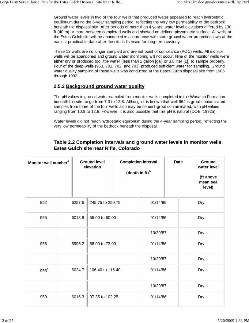
Ground water levels in two of the four wells that produced water appeared to reach hydrostaticequilibrium during the 6-year sampling period, reflecting the very low permeability of the bedrockbeneath the disposal site. After periods of more than 4 years, water level elevations differed by 130ft (40 m) or more between completed wells and showed no defined piezometric surface. All wells atthe Estes Gulch site will be abandoned in accordance with state ground water protection laws at theearliest practicable date after the site is licensed for long-term custody.
These 13 wells are no longer sampled and are not point of compliance (POC) wells. All monitorwells will be abandoned and ground water monitoring will not occur. Nine of the monitor wells wereeither dry or produced too little water (less than 1 gallon [gal] or 3.8 liter [L]) to sample properly.Four of the deep wells (963, 701, 702, and 703) produced sufficient water for sampling. Groundwater quality sampling of these wells was conducted at the Estes Gulch disposal site from 1986through 1992.
2.5.2 Background ground water quality
The pH values in ground water sampled from monitor wells completed in the Wasatch Formationbeneath the site range from 7.3 to 12.8. Although it is known that well 964 is grout-contaminated,samples from three of the four wells also may be cement-grout contaminated, with pH valuesranging from 10.9 to 12.8. However, it is also possible that this pH is natural (DOE, 1992a).
Water levels did not reach hydrostatic equilbrium during the 4-year sampling period, reflecting thevery low permeability of the bedrock beneath the disposal
Table 2.2 Completion intervals and ground water levels in monitor wells,Estes Gulch site near Rifle, Colorado
Monitor well numbera Ground levelelevation
Completion interval
(depth in ft)b
Date Groundwater level
(ft abovemean sea
level)
952 6257.6 245.75 to 250.75 01/14/86 Dry
955 6013.8 55.00 to 60.00 01/14/86 Dry
10/20/87 Dry
956 5995.2 58.00 to 73.00 01/14/86 Dry
10/20/87 Dry
958c 6024.7 106.40 to 116.40 01/14/86 Dry
10/20/87 Dry
959 6016.3 97.35 to 102.25 01/14/86 Dry
Long-Term Surveillance Plan for the Estes Gulch Disposal Site Near Rifle... http://lts1.lm.doe.gov/documents/rfl/ltsp.html
12 of 25 5/20/2009 1:38 PM

10/20/87 Dry
962c 6061.1 67.25 to 72.25 01/14/86 Dry
10/20/87 Dry
963c 6043.8 296.0 to 301.0 01/14/86 5773.55d
10/20/87 5860.75d
964c 6046.4 212.50 to 217.50 01/14/86 Dry
10/20/87 Dry
965 5987.0 97.25 to 102.75 01/14/86 Dry
10/20/87 Dry
969 6003.8 97.50 to 102.50 01/14/86 Dry
10/20/87 Dry
701 5979.0 180 to 545 07/28/88 5455
12/10/88 5581.81
03/24/89 5640.50
3/8/90 5710.10
3/19/92 5705.48
702 6008.0 355 to 543 07/28/88 5521
12/10/88 5519.91
03/24/89 5529.55
3/8/90 5542.38
3/19/92 5573.60
Long-Term Surveillance Plan for the Estes Gulch Disposal Site Near Rifle... http://lts1.lm.doe.gov/documents/rfl/ltsp.html
13 of 25 5/20/2009 1:38 PM
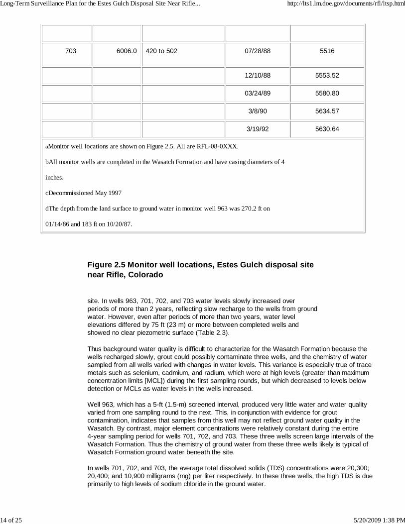
703 6006.0 420 to 502 07/28/88 5516
12/10/88 5553.52
03/24/89 5580.80
3/8/90 5634.57
3/19/92 5630.64
aMonitor well locations are shown on Figure 2.5. All are RFL-08-0XXX.
bAll monitor wells are completed in the Wasatch Formation and have casing diameters of 4
inches.
cDecommissioned May 1997
dThe depth from the land surface to ground water in monitor well 963 was 270.2 ft on
01/14/86 and 183 ft on 10/20/87.
Figure 2.5 Monitor well locations, Estes Gulch disposal sitenear Rifle, Colorado
site. In wells 963, 701, 702, and 703 water levels slowly increased overperiods of more than 2 years, reflecting slow recharge to the wells from groundwater. However, even after periods of more than two years, water levelelevations differed by 75 ft (23 m) or more between completed wells andshowed no clear piezometric surface (Table 2.3).
Thus background water quality is difficult to characterize for the Wasatch Formation because thewells recharged slowly, grout could possibly contaminate three wells, and the chemistry of watersampled from all wells varied with changes in water levels. This variance is especially true of tracemetals such as selenium, cadmium, and radium, which were at high levels (greater than maximumconcentration limits [MCL]) during the first sampling rounds, but which decreased to levels belowdetection or MCLs as water levels in the wells increased.
Well 963, which has a 5-ft (1.5-m) screened interval, produced very little water and water qualityvaried from one sampling round to the next. This, in conjunction with evidence for groutcontamination, indicates that samples from this well may not reflect ground water quality in theWasatch. By contrast, major element concentrations were relatively constant during the entire4-year sampling period for wells 701, 702, and 703. These three wells screen large intervals of theWasatch Formation. Thus the chemistry of ground water from these three wells likely is typical ofWasatch Formation ground water beneath the site.
In wells 701, 702, and 703, the average total dissolved solids (TDS) concentrations were 20,300;20,400; and 10,900 milligrams (mg) per liter respectively. In these three wells, the high TDS is dueprimarily to high levels of sodium chloride in the ground water.
Long-Term Surveillance Plan for the Estes Gulch Disposal Site Near Rifle... http://lts1.lm.doe.gov/documents/rfl/ltsp.html
14 of 25 5/20/2009 1:38 PM

Median levels of barium exceeded the U.S. Environmental Protection Agency (EPA) MCL in wells701, 702, and 703 and tended to increase as water levels in the wells increased. Median levels ofselenium exceeded the EPA MCL in the same three wells, though over the sampling period,concentrations decreased to levels less than the MCL. Cadmium and lead slightly exceeded theEPA MCLs in a few samples from the three wells, though median concentrations were below theMCL. Median levels of chromium and molybdenum exceeded the EPA MCL (0.1 mg per liter) inwells 702 and 703. The average combined radium-226 and -228 for samples from well 701 slightlyexceeded the UMTRA MCL (5 picocuries [pCi] per liter). Based on these data, ground water in theWasatch Formation beneath the disposal cell is of limited use and is not a potential source ofdrinking water because it contains more than 10,000 mg per liter TDS and because ambient levelsof barium, cadmium, chromium, lead, molybdenum, selenium, and combined radium-226 and -228have exceeded EPA MCLs (40 CFR Part 192).
Table 2.3 Summary of background water quality at the Estes Gulch disposalsite near Rifle, Colorado
Parameter MCL No. ofsamples
No. ofnondetects
Median Maximum
Barium 1 5 0 1.05 2
Cadmium 0.01 5 2 0.005 0.011
Chromium 0.05 5 0 0.07 0.99
Lead 0.05 5 2 0.015 0.04
Molybdenum 0.1 5 0 0.24 1.26
Total Radium 5 5 0 3 3.9
Selenium 0.01 5 2 0.029 0.212
Totaldissolvedsolids
NA 5 0 11900 12900
MCL - maximum concentration limit.
NA - not applicable.
Notes: 1. Based on data collected from wells 701, 702, and 703during the time period 1988 to 1992.
2. All values reported in units of milligrams per liter, except forradium -226 + radium -228, which is reported in picocuries perliter.
Long-Term Surveillance Plan for the Estes Gulch Disposal Site Near Rifle... http://lts1.lm.doe.gov/documents/rfl/ltsp.html
15 of 25 5/20/2009 1:38 PM
2.5.3 Hazardous constituents
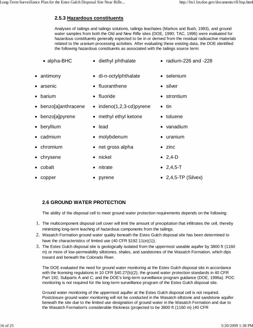
Analyses of tailings and tailings solutions, tailings leachates (Markos and Bush, 1983), and groundwater samples from both the Old and New Rifle sites (DOE, 1990; TAC, 1996) were evaluated forhazardous constituents generally expected to be in or derived from the residual radioactive materialsrelated to the uranium processing activities. After evaluating these existing data, the DOE identifiedthe following hazardous constituents as associated with the tailings source term:
alpha-BHC diethyl phthalate radium-226 and -228
antimony di-n-octylphthalate selenium
arsenic fluoranthene silver
barium fluoride strontium
benzo[a]anthracene indeno(1,2,3-cd)pyrene tin
benzo[a]pyrene methyl ethyl ketone toluene
beryllium lead vanadium
cadmium molybdenum uranium
chromium net gross alpha zinc
chrysene nickel 2,4-D
cobalt nitrate 2,4,5-T
copper pyrene 2,4,5-TP (Silvex)
2.6 GROUND WATER PROTECTION
The ability of the disposal cell to meet ground water protection requirements depends on the following:
The multicomponent disposal cell cover will limit the amount of precipitation that infiltrates the cell, therebyminimizing long-term leaching of hazardous components from the tailings.
1.
Wasatch Formation ground water quality beneath the Estes Gulch disposal site has been determined tohave the characteristics of limited use (40 CFR §192.11(e)(1)).
2.
The Estes Gulch disposal site is geologically isolated from the uppermost useable aquifer by 3800 ft (1160m) or more of low-permeability siltstones, shales, and sandstones of the Wasatch Formation, which dipstoward and beneath the Colorado River.
3.
The DOE evaluated the need for ground water monitoring at the Estes Gulch disposal site in accordancewith the licensing regulations in 10 CFR §40.27(b)(2); the ground water protection standards in 40 CFRPart 192, Subparts A and C; and the DOE’s long-term surveillance program guidance (DOE, 1996a). POCmonitoring is not required for the long-term surveillance program of the Estes Gulch disposal site.
Ground water monitoring of the uppermost aquifer at the Estes Gulch disposal cell is not required.Postclosure ground water monitoring will not be conducted in the Wasatch siltstone and sandstone aquiferbeneath the site due to the limited use designation of ground water in the Wasatch Formation and due tothe Wasatch Formation’s considerable thickness (projected to be 3800 ft (1160 m) (40 CFR
Long-Term Surveillance Plan for the Estes Gulch Disposal Site Near Rifle... http://lts1.lm.doe.gov/documents/rfl/ltsp.html
16 of 25 5/20/2009 1:38 PM

§192.11(e)(1)). Limited use ground water is ground water that is neither a current nor a potential source ofdrinking water because 1) the TDS concentration exceeds 10,000 mg per liter; 2) the existing widespreadambient contamination is unrelated to processing activities, and the contamination cannot be cleaned upusing treatment methods reasonably employed in public water supply systems; or 3) the quantity of wateravailable is less than 150 gal (570 L) per day.
3. 0 SITE INSPECTIONS
The DOE will inspect of the Estes Gulch disposal site to detect progressive changes caused by slow-actingnatural processes and to identify potential problems before there is a need for extensive maintenance, repairs, orcorrective action. Inspections may also be conducted to follow up on events or conditions that have affected orpotentially could affect the disposal site. The DOE will compare the findings from these inspections to initialbaseline conditions to identify changes over time and to provide a basis for future inspections, repairs, andcorrective actions. This process is shown in Figure 3.1.
Custodial maintenance or repair is discussed in Section 4.0. The corrective action process is outlined inSection 5.0.
3.1 INSPECTION FREQUENCY
The DOE will inspect the Estes Gulch disposal site annually. The DOE may schedule more frequentinspections if necessary. The DOE will notify the NRC of the inspection schedule.
3.2 INSPECTION TEAM
The inspection team will consist of a minimum of two inspectors qualified to inspect disposal cell integrityand make preliminary assessments of modifying processes that could adversely affect the disposal cell.
If problems are observed that require more investigation, follow-up inspections will be performed andteams will include one or more technical specialists in appropriate disciplines to assess the problems underinvestigation. For example, a follow-up inspection by a plant specialist may be required to evaluate reportsof significant plant growth on the rock cover, or a soils scientist or geomorphologist may be needed toevaluate erosion processes.
The inspection team will consist of a chief inspector and one or more assistants. The chief inspector will bea geotechnical engineer, a civil engineer, or an engineering geologist knowledgeable in the process thatcould adversely affect the site (e.g., geomorphic agents of change).
3.3 ANNUAL INSPECTION
Before inspections, inspectors will perform a preinspection briefing. The long-term surveillance programguidance (DOE, 1996a) contains information useful in preparing for inspections.
Site inspections will cover the disposal cell, the surrounding disposal site area, and the immediate off-siteareas. Site inspections must be thorough enough to identify significant changes or active modifyingprocesses that potentially could adversely affect the disposal cell: gully formation, slope erosion, changesto the rock cover, ephemeral drainage channel changes, and significant modifications by humans, animals,or plants.
Inspectors will measure and evaluate the leachate level in the monitor well leachate collection system(stand pipes) located on the 5 to 1 slope of the disposal cell.
Figure 3.1 Steps for follow-up inspections, custodial maintenance, and correctiveaction, at the Estes Gulch disposal site near Rifle, Colorado
Long-Term Surveillance Plan for the Estes Gulch Disposal Site Near Rifle... http://lts1.lm.doe.gov/documents/rfl/ltsp.html
17 of 25 5/20/2009 1:38 PM

Monitoring, corrective action, and closure of these wells will be performed in compliance with the plan asprovided in the operation and contingency plan (see appendix).
Inspectors will evaluate the integrity of the disposal cell by walking a series of transects around theperimeter and over the rock cover. Sufficient transects, at approximately 150-ft (46-m) intervals, must bewalked so that the disposal cell is thoroughly covered and inspected. Diagonal transects of the topslopeswill be made and the crest line will be walked. Additional transects will be walked along the sideslopes androck apron. Transects along the entire length of the diversion ditch will be made to determine whether it isfunctioning as designed and can be expected to continue to function properly. Inspectors will make effortsto vary the path of transects from one inspection to the next to ensure small anomalies are not overlooked.The sample inspection checklist in the LTSP guidance document lists items that should be examined duringinspections (DOE, 1996a).
The disposal cell has a rock cover and there is no planned vegetation on the disposal cell. However,remedial action of the areas surrounding the disposal cell included revegetation with grasses and sagebrush. The area surrounding the disposal cell will be monitored to determine the success of therevegetation efforts. Inspectors also will inspect this area for evidence of erosion caused by wind, sheetwash, or changes in drainage patterns.
Site inspectors also will monitor damage to or disturbance of permanent site-surveillance features, groundwater monitor wells (until they are decommissioned), fencing, locks, and the gate.
From inside the disposal site, inspectors will visually survey the area approximately 0.25 mi (0.40 km)outside the disposal site boundary for evidence of land-use changes that indicate increased human activity,such as land development or new roads and paths. Inspectors will note the condition of and changes tosite access roads, surrounding vegetation, and relevant geomorphic features like gullies or ephemeraldrainage channels; potential impacts to the site will be noted. Off-site DOE monitor wells will be inspecteduntil they are properly decommissioned.
3.4 FOLLOW-UP INSPECTIONS
In addition to annual inspections, DOE may conduct follow-up inspections due to unusual or annualinspection findings or observations. DOE also may conduct follow-up inspections to investigate and quantifyspecific problems found during a previous inspection, other DOE-initiated activity, or confirmed reports ofvandalism, intrusion, damage, unusual occurrences, or other significant threats to the disposal site. TheDOE will monitor the disposal cell area for the occurrence of extreme natural events (e.g., earthquakes,tornadoes, floods) and vandalism to ensure such events are investigated in a timely manner to assess theireffects on the disposal cell. To facilitate this, the DOE has requested notification from federal, state, andlocal agencies of discoveries or reports of any purposeful intrusion or damage at the disposal site as wellas in the disposal site area.
Notification agreements with the Garfield County Sheriff’s Office and the U.S. Geological Survey’s NationalEarthquake Information Center are included in Attachment 2. The DOE will also monitor the weather for theoccurrence of severe storms in the disposal cell vicinity. In addition, the DOE 24-hour telephone number isposted on the site entrance sign so the public can notify the DOE if problems are discovered. If an extremenatural event or vandalism has occurred, the DOE will inspect the cell to assess the damage. Thenotification, response, and follow-up activities will be documented. This documentation will be included inthe annual site report to the NRC and become part of the permanent site file.
The nature of the occurrence and the amount of firsthand knowledge available will determine the DOE’sresponse. If a situation is a threat to the public, the DOE will notify individuals who may be affected andappropriate federal, state, and local agencies, including the NRC. If necessary, the DOE will schedule afollow-up inspection to assess potential effects from the unusual occurrence, and will take necessaryresponse action. Follow-up inspections will be conducted to determine whether processes currently activeat or near the site threaten site security or stability and to evaluate the need for custodial maintenance,repair, or other corrective action. The scope of these follow-up inspections may be broad and similar in
Long-Term Surveillance Plan for the Estes Gulch Disposal Site Near Rifle... http://lts1.lm.doe.gov/documents/rfl/ltsp.html
18 of 25 5/20/2009 1:38 PM

nature to routine site inspections or focused on specific areas of concern.
During the follow-up inspection, inspectors and technical specialists will investigate reported problems todetermine whether the disposal cell has been damaged or threatened. The DOE will conduct additional sitevisits, if necessary to acquire data or plan maintenance and repairs.
3.5 QUALITY ASSURANCE
The DOE has developed and implemented a quality assurance plan (QA) (DOE, 1996d) for the siteinspection program that meets the requirements of DOE Order 5700.6C. Site inspections will be conductedin accordance with this QA plan.
4. 0 CUSTODIAL MAINTENANCE AND REPAIR
The DOE does not plan to conduct routine maintenance at the Estes Gulch disposal site. However, the DOE willperform needed custodial maintenance or repair as determined from site inspections.
Unscheduled custodial maintenance or repair required at the Estes Gulch disposal site may include the following:
Repairing or replacing deteriorated or vandalized warning signs, fencing, gate, and locks.Removal of deep-rooted plants determined to be a threat to the integrity of the cover.Reseeding areas surrounding the disposal cell.
After the work is completed, and before the contractors are released, DOE will verify that work was performedaccording to specification. The annual report to the NRC will document repairs that are performed. Copies ofrecords, reports, and certifications will be included in the permanent site file.
5. 0 CORRECTIVE ACTION
Corrective action is repairs that are needed to address problems that affect the integrity of the disposal cell orcompliance with 40 CFR Part 192. The NRC must approve the recommended action in advance.
Site inspections are designed to identify problems at the developmental stage. The following theoreticalconditions are examples that might trigger corrective action:
Surface rupture or subsidence of the disposal cell.
Development of rills, gullies, or slope instability on the disposal cell.
Deterioration of the erosion-protection rock on the disposal cell.
Tailings fluid originating from the disposal cell.
Gully development on or immediately adjacent to disposal site property that could affect the integrity of thedisposal cell.
Damage to the cell cover or disposal site property from natural catastrophic events or vandalism.
Damage to the disposal cell cover from deep-rooted plant growth.
The DOE will evaluate the factors that caused the problem and identify actions to mitigate the impact and preventrecurrence. An on-site inspection or preliminary assessment will include, but is not limited to, the following:
Long-Term Surveillance Plan for the Estes Gulch Disposal Site Near Rifle... http://lts1.lm.doe.gov/documents/rfl/ltsp.html
19 of 25 5/20/2009 1:38 PM

Identifying the nature and extent of the problem.Reevaluating germane engineering design parameters.
When a potential problem is identified, the DOE will submit a preliminary assessment report to the NRC for reviewno more than 60 days after the problem is identified. The preliminary assessment report will evaluate the problemand recommend the next step (e.g., immediate action or continued evaluation). If the problem requires immediaterepair, the DOE will develop a corrective action plan for NRC approval. Once the NRC approves the correctiveaction, the DOE will implement the plan. In some cases, corrective action could include temporary emergencymeasures instituted prior to the completion of the normal approval process. If the problem does not requireimmediate repair, the problem will be documented in the annual report and assessed at the next annualinspection.
NRC regulations do not stipulate a time frame for implementing corrective action (except the finding of anexceedance in established ground water concentration limits, which does not apply to this site). The DOE doesnot consider assessing the extent of a problem and developing a corrective action plan to be initiation of thecorrective action program.
In addition to the preliminary assessment report, the DOE may (as appropriate) prepare a progress report oncorrective actions while they are under way or under evaluation.
After corrective action is complete, the DOE will certify work and submit a certification statement and supportingdocumentation to the NRC for review and concurrence. A copy of the certification statement will become part ofthe permanent site file, as will reports, data, and documentation generated during the corrective action.
6. 0 RECORD KEEPING AND REPORTING
6.1 PERMANENT SITE FILE
The DOE will maintain a permanent site file containing site inspection reports and other supportingdocumentation of long-term surveillance program activities. The information placed in the site file willinclude:
Documentation of disposal site performance.Demonstration that licensing provisions were met.Information needed to forecast future site-surveillance and monitoring needs.Reports to stakeholders regarding disposal cell integrity.
After the site is brought under the general license, the DOE will compile copies of site documentationrequired by the long-term surveillance program guidance for the disposal site permanent site file (DOE,1996a). Copies of all deeds, custody agreements, and other property documents will be kept in this file.
The DOE will maintain the surveillance and maintenance documentation identified in other sections of thisLTSP; it will become part of the permanent site file. The DOE will update the site file as necessary afterdisposal site inspections, maintenance activities, or corrective actions are complete. These records will behandled in accordance with DOE directives to ensure their proper handling, maintenance, and disposition.The archival procedures set forth in 41 CFR Part 101 and 36 CFR Parts 1220-1238, Subchapter B, will befollowed. The permanent site file information will be available for NRC and public review.
6.2 INSPECTION REPORTS/ANNUAL REPORTS
During site inspections, activities and observations will be recorded and described using site inspectionchecklists, maps, photographs and photo logs, and field notes. Documentary evidence of anomalous, new,or unexpected conditions or situations must describe developing trends and enable the DOE to make
Long-Term Surveillance Plan for the Estes Gulch Disposal Site Near Rifle... http://lts1.lm.doe.gov/documents/rfl/ltsp.html
20 of 25 5/20/2009 1:38 PM

decisions concerning follow-up inspections, custodial maintenance, and corrective action. This informationwill be contained in the permanent site file at the DOE office. The DOE will prepare a site inspection reportdocumenting the findings and recommendations from field inspections.
Site inspection reports will be submitted to the NRC within 90 days of the annual site inspection. Inspectionreports will summarize the results of follow-up inspections and maintenance completed since the previousannual site inspection.
If unusual damage or disruption is discovered at the disposal site during an inspection, a preliminary reportassessing the impact must be submitted to the NRC within 60 days. If maintenance, repair, or correctiveaction is warranted, the DOE will notify the NRC. The NRC will receive a copy of corrective action plansand corrective action progress reports, or the reports will be attached to the annual report.
The DOE also will provide copies of inspection reports and other generated under the long-termsurveillance program to the state of Colorado as required in their cooperative agreement.
7. 0 REFERENCES
Coffin et al. (D. L. Coffin, F. A. Welder, and R. K. Glanzman), 1971. Geohydrology of the Piceance Creek BasinBetween the White and Colorado Rivers, Northwestern Colorado, U.S. Geological Survey HydrologicInvestigations Atlas HA-370, U.S. Geological Survey.
Coffin et al. (D. L. Coffin, F. A. Welder, and R. K. Glanzman), 1968. Geohydrologic Data From the PiceanceCreek Basin Between the White and Colorado Rivers, Northwestern Colorado, U.S. Geological Survey Circular12, Ground-Water Series, prepared by the U.S. Geological Survey in cooperation with the Colorado WaterConservation Board, Denver, Colorado.
DOE (U.S. Department of Energy), 1997. Rifle, Colorado, Final Completion Report, prepared for the U.S.Department of Energy by Morrison Knudsen Corporation, Albuquerque, New Mexico.
DOE (U.S. Department of Energy), 1996a. Guidance for Implementing the Long-Term Surveillance Program forUMTRA Project Title I Disposal Sites, DOE/AL-62350-189, Rev. 0, prepared for the U.S. Department of Energy,Environmental Restoration Division, UMTRA Project Team, Albuquerque, New Mexico.
DOE (U.S. Department of Energy), 1996b. Uranium Mill Tailings Remedial Action Project (UMTRAP), Rifle,Colorado, Long-Term Surveillance Plan Subcontract Documents, Final Design for Review, prepared for the U.S.Department of Energy by Morrison Knudsen Corporation, Albuquerque, New Mexico.
DOE (U.S. Department of Energy), 1996c. UMTRA Project Rifle, Colorado, Operation and Contingency Plan forMonitoring Well Closure, Estes Gulch Disposal Cell, UMT-79635, prepared for the U.S. Department of Energyby Morrison Knudsen Corporation, San Francisco, California.
DOE (U.S. Department of Energy), 1996d. Long-Term Surveillance and Maintenance Program, QualityAssurance Program Plan, MAC-2152, Rev. 0, prepared by MACTEC Environmental Restoration Services, for theU.S. Department of Energy, Grand Junction Office, Grand Junction, Colorado.
DOE (U.S. Department of Energy), 1992a. Remedial Action Plan for Stabilization of the Inactive Uranium MillTailings Site at Rifle, Colorado, UMTRA-DOE/AL-050506.0000, prepared for the U.S. Department of Energy,UMTRA Project Office, Albuquerque Operations Office, Albuquerque, New Mexico.
DOE (U.S. Department of Energy), 1990. Final Environmental Impact Statement, Remedial Actions at theFormer Union Carbide Corporation Uranium Mill Sites, Rifle, Garfield County, Colorado, DOE/EIS-0132-F,prepared for the U.S. Department of Energy, UMTRA Project Office, Albuquerque Operations Office,Albuquerque, New Mexico.
Giles, T. F., 1980. Reconnaissance of Groundwater Resources in the Vicinity of Gunnison and Crested Butte,West-Central Colorado, USGS Open File Report 80-12, January.
Long-Term Surveillance Plan for the Estes Gulch Disposal Site Near Rifle... http://lts1.lm.doe.gov/documents/rfl/ltsp.html
21 of 25 5/20/2009 1:38 PM

Markos, G., and K. J. Bush, 1983. Data for the Geochemical Investigation of UMTRAP Designated Sites at Rifle,Colorado, prepared by Geochemistry and Environmental Chemistry Research, Inc., Rapid City, South Dakota, forthe U.S. Department of Energy, UMTRA Project Office, Albuquerque Operations Office, Albuquerque, NewMexico.
MK-F (Morrison Knudsen-Ferguson), 1996. Meteorological tower data, December 1993 through August 1996,Estes Gulch site, Rifle, Colorado, UMTRA Project site, UPDCC File Location No. 6.15.5., Albuquerque, NewMexico.
TAC (Technical Assistance Contractor), 1996. Data package for February 1996 Rifle, Colorado, sample analysis,unpublished report prepared by the Technical Assistance Contractor, Albuquerque, New Mexico, for the U.S.Department of Energy, Albuquerque, New Mexico.
Tweto et al. (O. Tweto, R. H. Moench, and J. C. Reed, Jr.), 1978. Geologic map of the Leadville 1' x 2'quadrangle, northwestern Colorado, U.S. Geological Survey Miscellaneous Series, Map I-999, Washington, D.C.
Wright Water Engineers, 1979. Garfield County water resource map, prepared by Wright Water Engineers,Glenwood Springs, Garfield County, Colorado.
Yeend, W. E., 1969. Quaternary Geology of the Grand and Battlement Mesas Area, Colorado, U.S. GeologicalSurvey, Professional Paper 617, Washington, D.C.
CODE OF FEDERAL REGULATIONS
10 CFR Part 40, Domestic Licensing of Source Material, U.S. Nuclear Regulatory Commission.
36 CFR Parts 1220-1238, National Archives and Records, Subchapter B - Records Management,National Archives and Records Administration.
40 CFR Part 192, Health and Environmental Protection Standards for Uranium and Thorium Mill Tailings,U.S. Environmental Protection Agency.
41 CFR Part 101, Federal Property Management Regulations, General Services Administration.
DOE ORDERS
Order 5700.6C, Quality Assurance, 21 August 1991, U.S. Department of Energy, Washington, D.C.
Long-Term Surveillance Plan for the Estes Gulch Disposal Site Near Rifle... http://lts1.lm.doe.gov/documents/rfl/ltsp.html
22 of 25 5/20/2009 1:38 PM

UNITED STATES CODE
42 USC §7901 et seq., Uranium Mill Tailings Radiation Control Act, 8 November 1978.
SITE REAL ESTATE INFORMATION
GENERAL
The Uranium Mill Tailings Radiation Control Act (UMTRCA) of 1978, as amended, required the Secretaryof Energy to permanently acquire lands needed to carry out the purposes of the UMTRCA (42 USC §7901et seq.). The U.S. Department of Energy (DOE) located the Rifle, Colorado, disposal site on public landadministered by the U.S. Department of the Interior’s BLM.
JURISDICTIONAL TRANSFER OF THE DISPOSAL SITE
Under the authority vested in the Secretary of the Interior by the UMTRCA, the BLM transferredadministration of approximately 205 acres (83 hectares) of public land in Garfield County, Colorado, to theDOE. Publication in the Federal Register (Vol. 56, No. 167, p. 42450, FR Doc. 91-20555) of Public LandOrder (PLO) 6873 established the effective date of the transfer as 28 August 1991. As a result of thispermanent transfer, the land is no longer subject to the operation of the general land laws, including miningand mineral leasing. The transfer vested in the DOE the full management, jurisdiction, and liability for theland and all activities conducted thereon.
LEGAL DESCRIPTION
The legal description contained in the PLO describes the disposal site area as follows:
Township 5 South, Range 93 West, Sixth Principal Meridian.
Section 11: S1/2 S1/2 SW1/4 SW1/4 SE1/4; Section 14: NW1/4 NW1/4 NE1/4, W1/2 SW1/4NW1/4 NE1/4, W1/2 W1/2 SW1/4 NE1/4, E1/2 NE1/4 NW1/4, E1/2 NW1/4 NE1/4 NW1/4,SW1/4 NE1/4 NW1/4, SE1/4 SE1/4 NW1/4 NW1/4, NE1/4 NE1/4 SW1/4 NW1/4, S1/2 NE1/4SW1/4 NW1/4, SE1/4 SW1/4 NW1/4, SE1/4 NW1/4, NE1/4 SW1/4, NE1/4 NW1/4 SW1/4,E1/2 E1/2 NW1/4 NW1/4 SW1/4, W1/2 NW1/4 SE1/4, and W1/2 W1/2 NW1/4 SE1/4,containing approximately 205 acres (83 hectares).
Long-Term Surveillance Plan for the Estes Gulch Disposal Site Near Rifle... http://lts1.lm.doe.gov/documents/rfl/ltsp.html
23 of 25 5/20/2009 1:38 PM

References
42 USC §7901 et seq., Uranium Mill Tailings Radiation Control Act, 8 November 1978.
ATTACHMENT 1
SITE REAL ESTATE INFORMATION
Available Upon Request - Click here to email a request
ATTACHMENT 2
AGENCY NOTIFICATION AGREEMENTS
Available Upon Request - Click here to email a request
APPENDIX
OPERATION AND CONTINGENCY PLAN
FOR MONITORING WELL CLOSURE, ESTES GULCH DISPOSAL CELL
Long-Term Surveillance Plan for the Estes Gulch Disposal Site Near Rifle... http://lts1.lm.doe.gov/documents/rfl/ltsp.html
24 of 25 5/20/2009 1:38 PM

Available Upon Request - Click here to email a request
Long-Term Surveillance Plan for the Estes Gulch Disposal Site Near Rifle... http://lts1.lm.doe.gov/documents/rfl/ltsp.html
25 of 25 5/20/2009 1:38 PM