Embed Size (px)
Citation preview
II'll"I
LM S/DU D/S06297-0.0
Long-Term Surveillance Planfor the Durango Disposal Site,Durango, Colorado
January 2011
' U.S. DEPARTMENT OF Legacy"JENERGY Management
0I
This page intentionally left blank I
LMS/DUD/SO6297-0.0
Long-Term Surveillance Plan
for the
Durango Disposal Site, Durango, Colorado
January 2011
This page intentionally left blank
Contents
Abbreviations............................................................................................... v1.0 Introduction ....................................................................................... 1-i
1.1 Purpose ..................................................................................... 1-i1.2 Legal and Regulatory Requirements .................................................... 1-11.3 Role ofDOE............................................................................... 1-2-
2.0 Final Site Conditions............................................................................. 2-12.1 Site History ................................................................................ 2-12.2 Description of the Disposal Site and Vicinity .......................................... 2-1
2.2 '.1 Site Description.................................................................... 2-12.2.2 Legal Description.................................................................. 2-42.2.3 Location and Access .............................................................. 2-42.2.4 Disposal Cell Description ........................................................ 2-42.2.5 Transient Drainage System....................................................... 2-92.2.6 Institutional Controls.............................................................. 2-92.2.7 Permanent Site Surveillance Features ........................................... 2-92.2.8 Site Drawings and Photographs ................................................ 2-10
2.3 Geology, Hydrology, and Groundwater................................................ 2-182.3.1 Site Geology ...................................................................... 2-182.3.2 Bedrock Hydrology .............................................................. 2-242.3.3 Alluvium Hydrology............................................................. 2-242.3.4 Background Groundwater Quality.............................................. 2-252.3.5 Hazardous Constituents ......................................................... 2-262.3.6 Concentration Limits for Hazardous Constituents ............................ 2-27
3.0 Long-Term Surveillance Program............................................................... 3-13.1 General License for Long-Term Custody ............................................... 3-13.2 Requirements of the General License ................................................... 3-13.3 Annual Site Inspections................................................................... 3-1
3.3.1 Inspection Frequency ............................................................. 3-13.3.2 Personnel ........................................................................... 3-23.3.3 Inspection Procedure .............................................................. 3-23.3.4 Inspection Checklist............................................................... 3-33.3.5 Site Inspection Map............................................................... 3-33.3.6 Annual Inspection Report ........................................................ 3-3
3.4 Follow-up Inspections .................................................................... 3-33.4.1 Criteria for Follow-Up Inspections .............................................. 3-33.4.2 Personnel ........................................................................... 3-43.4.3 Reports.............................................................................. -3.4.4 Beneficial Reuse Inspections ..................................................... -
3.5 Routine Site Maintenance and Emergency Measures ................................. 3-53.5.1 Criteria for Routine Site Maintenance and Emergency Measures ............ 3-53.5.2 Reporting Maintenance and Emergency Measures............................. 3-5
3.6 Environmental Monitoring............................................................... 3-63.6.1 Groundwater Monitoring ......................................................... 3-63.6.2 Vegetation Monitoring............................................................ 3-9
3.7 Records ..................................................................................... 3-93.8 Quality Assurance......................................................................... 3-9
U.S. Department of Energy LTSP-Durango Disposal Site, Durango, ColoradoJanuary 2011 Doc. No. S06297-0.0
Page
3.9 Health and Safety ........................................................................ 3-104.0 Beneficial Reuse Project ........................................................................ 4-1 I
4.1 Scope ....................................................................................... 4-14.2 National Environmental Policy Act ..................................................... 4-1
4.3 Long-Term Lease Requirements......................................................... 4-14.4 Potential Reuse Impacts .................................................................. 4-24.5 Minimum Technical Requirements...................................................... 4-2 '
4.5.1 Disposal Cell Cover............................................................... 4-24.5.2 Entire Site .......................................................................... 4-3
5.0 References ........................................................................................ 5-1 'Figures1
Figure 2-1. Location of the Durango Disposal Site, La Plata County, Colorado ................ 2-2Figure 2-2. Area Map of the Durango, Colorado, Disposal Site .................................. 2-3IFigure 2-3. As-Built Cross Section of Cover System, Durango, Colorado, Disposal Cell.....2-6
Figure 2-4. Top Slope Cover System, Durango, Colorado, Disposal Cell ....................... 2-7Figure 2-5. Embankment Features Durango, Colorado, Disposal Cell ........................... 2-8Figure 2-6. Map of the Durango, Colorado, Disposal Site ....................................... 2-11Figure 2-7. Site Marker, Durango, Colorado, Disposal Site...................................... 2-145Figure 2-8. Entrance Sign, Durango, Colorado, Disposal Site ................................... 2-15Figure 2-9. Perimeter Sign, Durango, Colorado, Disposal Site .................................. 2-16Figure 2-10. Locations of Monitoring Wells and Cross Sections, Durango, Colorado,
Disposal Site ........................................................................... 2-19Figure 2-11. Cross Section A-A', Durango, Colorado, Disposal Site .......................... 2-20Figure 2-12. Cross Section B-B3', Durango, Colorado, Disposal Site........................... 2-21Figure 2-13. Cross Section C-C', Durango, Colorado, Disposal Site........................... 2-22IFigure 2-14. Cross Section D-D', Durango, Colorado, Disposal Site .......................... 2-23Figure 3-1. Existing Wells at the Durango, Colorado, Disposal Site ............................. 3-7
Tables3
Table 1-1. Requiremen 'ts for the Long-Term Surveillance Plan and the Long-Term
Surveillance and Maintenance of the Durango, Colorado, Disposal Site............. 1-1Table 2-1.Site Surveillance Feature Location Coordinates....................................... 2-13Table 2-2. Summary of Background Groundwater Quality, Durango, Colorado,
Disposal Site.............................................................................. 2-26 'Table 2-3. Concentration Limits for Hazardous Constituents in Tailings Solutions,
Durango, Colorado, Disposal Site...................................................... 2-28Table 3-1. Requirements of the General License and DOE Response............................ 3-1Table 3-2. Transects for the Annual Inspection of the Durango, Colorado, Disposal Site .....3-2Table 3-3. DOE Criteria for Maintenance and Emergency Measures............................. 3-5
Table 3-4. Groundwater Monitoring Requirements for the Durango Disposal Site ............. 3-6
LTSP-Durango Disposal Site, Durango, Colorado U.S. Department of Energy
Doc. No. S06297-0.0 January 2011I
Appendixes
Appendix A NRC Concurrence and Licensing DocumentationAppendix B Site Ownership/Custody DocumentationAppendix C Inspection Checklist and Photo LogAppendix D Reuse Potential Impacts Matrix
U.S. Department of EnergyJanuary 2011
LTSP-Durango Disposal Site, Durango, ColoradoDoc. No. S06297-0.0
Page iii
This page intentionally left blank
IUpIII'IU*1IUU1'N
UU1IU
U.S. Department of Energy
January2011 ULTSP-Durango Disposal Site, Durango, ColoradoDoe. No. S06297-0.0Page iv
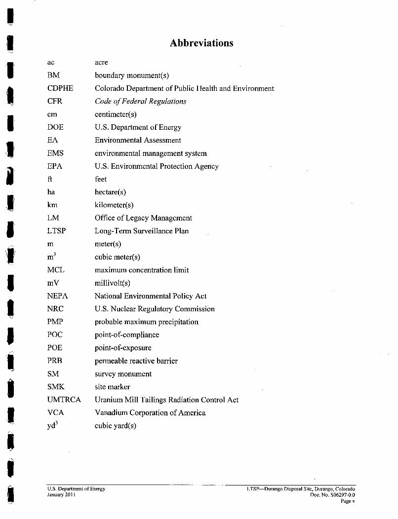
Abbreviations
ac
BM
CDPHE
CFR
cm
DOE
EA
EMS
EPA
ft
ha
km
LM
LTSPmmn3
MCL
mV
NEPA
NRC
PMP
POC
POE
PRB
SM
SMK
UMTRCA
VCA
yd3
acre
boundary monument(s)
Colorado Department of Public Health and Environment
Code of Federal Regulations
centimeter(s)
U.S. Department of Energy
Environmental Assessment
environmental management system
U.S. Environmental Protection Agency
feet
hectare(s)
kilometer(s)
Office of Legacy Management
Long-Term Surveillance Plan
meter(s)
cubic meter(s)
maximum concentration limit
millivolt(s)
National Environmental Policy Act
U.S. Nuclear Regulatory Commission
probable maximum precipitation
point-of-compliance
point-of-exposure
permeable reactive barrier
survey monument
site marker
Uranium Mill Tailings Radiation Control Act
Vanadium Corporation of America
cubic yard(s)
U.S. Department of EnergyJanuary 2011
LTSP-Durango Disposal Site, Durango, ColoradoDoc. No. S06297-0.0
Page v
This page intentionally left blank
LTSP-Durango Disposal Site, Durango, ColoradoDoc. No. S06297-0.0Page vi
U.S. Department of EnergyJanuary 2011
1.0 Introduction
1.1 Purpose
This Long-Term Surveillance Plan (LTSP) explains how the U.S. Department of Energy (DOE),as long-term custodian, will comply with the requirements of the general license for custody andlong-term care of the Durango, Colorado, uranium mill tailings disposal site.
The Durango disposal site was licensed on June 18, 1996. The U.S. Nuclear RegulatoryCommission (NRC) concurred with the original LTSP in September 1996 (Appendix A).Thisrevised LTSP incorporates the potential for beneficial reuse of some of the Durango DisposalSite property see Section 4.0 Beneficial Reuse Project for details.
1.2 Legal and Regulatory Requirements
Federal regulations in Title 10 Code of Federal Regulations Part 40.27 (10 CFR 40.27)provide for the licensing, custody, and long-term care of uranium mill tailings disposal sitesremediated under Title I of the Uranium Mill Tailings Radiation Control Act (UMTRCA) of1978 (Title 42 United States Code §7901 et seq.). NRC regulates a general license for the long-term custody and care of these sites. Long-term care includes institutional controls, inspection,monitoring, maintenance, and other measures to ensure that the sites continue to protect publichealth and the environment after remediation is completed (Table 1-1). Concurrence from NRCon the remedial action plan was received October 16, 1995 (Appendix A).
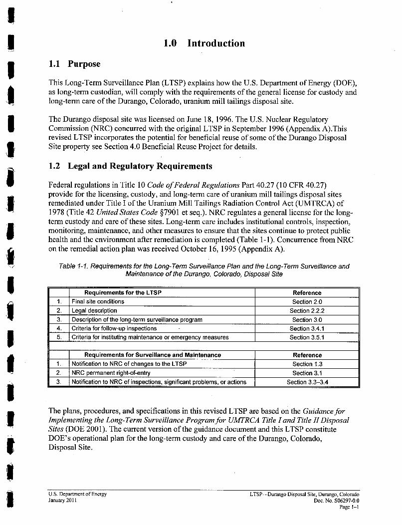
Table 1-1. Requirements for the Long-Term Surveillance Plan and the Long-Term Surveillance andMaintenance of the Durango, Colorado, Disposal Site
Requirements for the LTSP Reference1. Final site conditions Section 2.02. Legal description Section 2.2.23. Description of the long-term surveillance program Section 3.04. Criteria for follow-up inspections Section 3.4.15. Criteria for instituting maintenance or emergency measures Section 3.5.1
Requirements for Surveillance and Maintenance Reference1. Notification to NRC of changes to the LTSP Section 1.32. NRC permanent right-of-entry Section 3.13. Notification to NRC of inspections, significant problems, or actions Section 3.3-3.4
The plans, procedures, and specifications in this revised LTSP are based on the Guidance forImplementing the Long-Term Surveillance Program for UMTRCA Title land Title II DisposalSites (DOE 2001). The current version of the guidance document and this LTSP constituteDOE's operational plan for the long-term custody and care of the Durango, Colorado,Disposal Site.
U.S. Department of EnergyJanuary 2011
LTSP-Durango Disposal Site, Durango, ColoradoDoc. No. S06297-0.0
Page 1-1

II1.3 Role of DOE
In 1988, DOE designated the Grand Junction, Colorado, facility, to be the program office for thelong-term surveillance and maintenance of all Uranium Mill Tailings Remedial Action Projectdisposal sites, as well as other sites as assigned, and to be the common office for the surveillance,monitoring, maintenance, and institutional control of these sites. DOE established the Long-Term Surveillance and Maintenance Program to carry out this responsibility. In 2003, DOEcreated the Office of Legacy Management (LM) at DOE Headquarters. LM assumed theresponsibility for long-term surveillance and maintenance of remediated sites and is responsiblefor implementing and revising this LTSP. I
III
UI
LTSP-Durango Disposal Site, Durango, ColoradoDoc. No. S06297-0.0Page 1-2
U.S. Department of EnergyJanuary 2011 I
2.0 Final Site Conditions
2.1 Site History
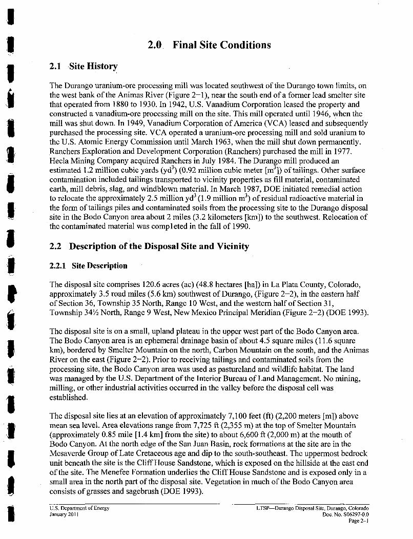
The Durango uranium-ore processing mill was located southwest of the Durango town limits, onthe west bank of the Animas River (Figure 2-1), near the south end of a former lead smelter sitethat operated from 1880 to 1930. In 1942, U.S. Vanadium Corporation leased the property andconstructed a vanadium-ore processing mill on the site. This mill operated until 1946, when themill was shut down. In 1949, Vanadium Corporation of America (VCA). leased and subsequentlypurchased the processing site. VCA operated a uranium-ore processing mill and sold uranium tothe U.S. Atomic Energy Commission until March 1963, when the mill shut down permanently.Ranchers Exploration and Development Corporation (Ranchers) purchased the mill in 1977.Hecla Mining Company acquired Ranchers in July 1984. The Durango mill produced anestimated 1.2 million cubic yards (yd 3) (0.92 million cubic meter [mi3]) of tailings. Other surfacecontamination included tailings transported to vicinity properties as fill material, contaminatedearth, mill debris, slag, and windblown material. In March 1987, DOE initiated remedial actionto relocate the approximately 2.5 million yd3 (1.9 million m3) of residual radioactive material inthe form of tailings piles and contaminated soils from the processing site to the Durango disposalsite in the Bodo Canyon area about 2 miles (3.2 kilometers [km]) to the southwest. Relocation ofthe contaminated material was comp l eted in the fall of 1990.
2.2 Description of the Disposal Site and Vicinity
2.2.1 Site Description
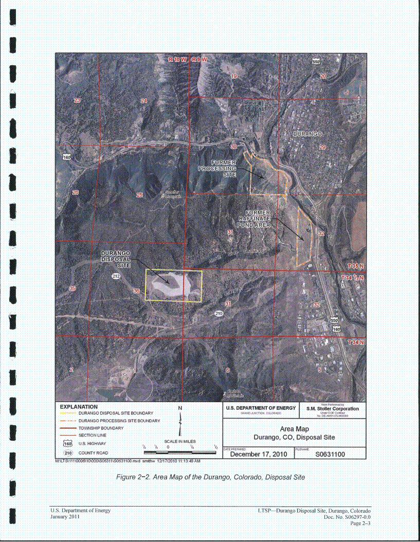
The disposal site comprises 120.6 acres (ac) (48.8 hectares [ha]) in La Plata County, Colorado,approximately 3.5 road miles (5.6 km) southwest of Durango, (Figure 2-2), in the eastern halfof Section 36, Township 35 North, Range 10 West, and the western half of Section 3.1,Township 34½ North, Range 9 West, New Mexico Principal Meridian (Figure 2-2) (DOE 1993).
The disposal site is on a small, upland plateau in the upper west part of the Bodo Canyon area.The Bodo Canyon area is an ephemeral drainage basin of about 4.5 square miles (11.6 squarekm), bordered by Smelter Mountain on the north, Carbon Mountain on the south, and the AnimasRiver on the east (Figure 2-2). Prior to receiving tailings and contaminated soils from theprocessing site, the Bodo Canyon area was used as pastureland and wildlife habitat. The landwas managed by the U.S. Department of the Interior Bureau of Land Management. No mining,milling, or other industrial activities occurred in the valley before the disposal cell wasestablished.
The disposal site lies at an elevation of approximately 7,100 feet (ft) (2,200 meters [m]) abovemean sea level. Area elevations range from 7,725 ft (2,355 m) at the top of Smelter Mountain(approximately 0.85 mile [1.4 km] from the site) to about 6,600 ft (2,000 m) at the mouth ofBodo Canyon. At the north edge of the San Juan Basin, rock formations at the site are in theMesaverde Group of Late Cretaceous age and dip to the south-southeast. The uppermost bedrockunit beneath the site is the Cliff House Sandstone, which is exposed on the hillside at the east endof the site. The Menefee Formation underlies the Cliff House Sandstone and is exposed only in asmall area in the north part of the disposal site. Vegetation in much of the Bodo Canyon areaconsists of grasses and sagebrush (DOE 1993).
U.S. Department of Energy LTSP-Durango Disposal Site, Durango, ColoradoJanuary 2011 Doc. No. S06297-0.0
Page 2-1
IIDenver
S COLORADOIDwrango
. Silvert 2!
FANi MAN CC)
,.. DO
A ,Ur ngo
LocationA of Durango Disposal Site j
Figure 2-I. Location of the Durango Disposal Site, La Plata County, Colorado
LTSP--Durango Disposal Site, Durango, Colorado uJ. eartmentyfEnergDoc. No. S06297-0.0
Pagenng 2-2
EXPLANATIONDURANGO DISPOSAL SITE BOUNDARY
.... DURANGO PROCESSING STE BOUNDARY
-TOVYNSHIP BOUNDARY
SECTION LINE
U.S. DEPARTMENT OF ENERGY S.M.
Area MapDuran]o. CO. Disnosal Site
U..HG V YSCALE IN MILES . . . ,- - -- ". . ..U.S/ HIGHWAY ' 0 14 1I
I21O0) COUNTY ROAD IDecember 17, 2010 S0631100M:\LTSt111\000610'•00..S06311S.0631100.rnud smghw 12/17/2010 11-1349 AM
Figure 2-2. Area Map of the Durango, Colorado, Disposal Site
U.S. Department of Energy LTSP-Durango Disposal Site, Durango, ColoradoJanuary 2011 Doc. No. S06297-0.0
Page 2-3
2.2.2 Legal Description
The disposal site consists of 120.6 ac that was acquired in two parcels, which were historicallyidentified as Tracts 101 and 102. Both parcels were acquired by the Colorado Department ofPublic Health and Enviromnnent (CDPHE) and were deeded by quitclaim to the United States ofAmerica in August 1996. Tract 101 contains approximately 39 ac, and Tract 102 contains theremaining 81 ac. Appendix B provides copies of the quitclaim deeds and details the legaldescriptions for both tracts.
2.2.3 Location and Access
Figure 2-2 is a map of the Durango, Colorado, area. The disposal site can be accessed using thefollowing directions:
1. Where U.S. Highway 160 joins U.S. Highway 550 (US-550/160) just west of downtownDurango, proceed south on US-550/160.
2. Turn west (right) on County Road 210 (CR 210), known as Bodo Canyon Road, which soonbecomes a dirt road.
3. Remain on CR 210, heading southwest.
4. An electrical substation is on the right side of the road. Remain on CR 210.
5. Turn northwest (right) onto CR 212. Proceed northwest.
6. Turn north (right) onto the entrance road.
The site entrance gate is at the southwest corner of the site.
2.2.4 Disposal Cell Description
The disposal cell is constructed partially below existing grade. It covers approximately 60 ac(24 ha), with maximum areal dimensions of 2,400 x 1,300 ft (730 x 400 in).
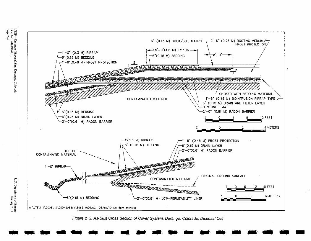
The radon barrier thickness was designed to be conservative, based upon radiologicalcharacterization of the contaminated materials obtained prior to and during construction. Theradon emanation rate from the completed disposal cell meets the U.S. Environmental ProtectionAgency's (EPA) standard of 20 picocuries per square meter per second. The tailings wereencapsulated with a compacted 2-ft (0.6-m)-thick radon barrier layer of uncontaminated siltyclay and clay materials. On the side slope, the upper 18 inches (46 centimeters [cm]) of the radonbarrier was amended with 7 percent bentonite to maintain a consistent radon barrier thickness onthe top and sides of the cell. Additionally, the radon barrier on the top slope was constructed witha bentonite mat (bentonite sandwiched between two geotextile membranes) on the surface torestrict infiltration into the barrier. The radon barrier is further protected by a 6-inch(15-cm)-thick sand filter/drainage layer on the side slopes and top.
LTSP-Durango Disposal Site, Durango, Colorado U.S. Department of EnergyDoc. No. S06297-0.0 January 2011Page 2--4
The top slope was completed with a 1.5-ft (0.5-m)-thick biointrusion layer, a 2.5-ft (0.8-m)-thickfrost-protection layer of compacted soil, and a 6-inch (1 5-cm)-thick rock/soil matrix. The matrixhas a 1.5 to 2.0 percent grade away from a drainage divide at the center of the cell. The cell topslope is covered with native grasses. The cover system for the embankment top slope isillustrated in Figure 2-3 and Figure 2-4.
The top slope was planted with the following seed mixture:
Smooth bromeKentucky bluegrassWestern wheatgrassBlue gramaGalletaTotal
4.1 lb/ac (4.6 kg/ha)3.4 lb/ac (3.8 kg/ha)3.9 lb/ac (4.4 kg/ha)3.65 lb/ac (4.1 kg/ha)1.95 lb/ac (2.2 kg/ha)17.0 lb/ac (19.1 kg/ha)
The side slope was completed with a 6-inch (1 5-cm)-thick bedding layer, a 1.5-ft (0.5-m)-thickfrost-protection layer, another 6-inch (15-cm)-thick bedding layer, and a 1.0-ft (0.3-m)-thickriprap layer. The riprap is keyed into the surrounding surface at the toe of the slope to preventheadcutting erosion at the cell boundary.
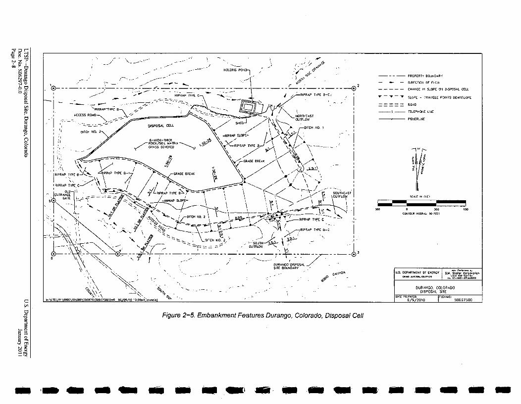
The drainage features of the embankment and general site grading ensure long-term embankmentstability as required in 40 CFR 192.02(b) (Figure 2-5). Runoff from the embankment flows tothe apron and then to the adjacent natural ground on the northern slope of the cell. All other sideslopes of the cell drain to perimeter catchment ditches that channel the concentrated flows tooutfall structures. Ditch No. 1 carries run off from the eastern slope and drains to an outfallstructure into the North Side Drainage. Ditch No. 2 carries run off from the southern face of thecell eastward to an outfall structure that drains into Bodo Canyon. Ditch No. 3 captures a smallerdrainage from the northwestern and western slopes of the cell and a small upland drainage area.The eastern part of this ditch drains to the North Side Drainage, and the western part drains to theSouth Side Drainage. The ditches have sufficient depth and rock protection to carry runoff froma probable maximum precipitation (PMP) event. Significant precipitation events can createvelocities capable of moving sediment buildup in the ditches. Flows in the North and South SideDrainages off of the cell, produced from a PMP event in the upland drainage area, will notimpact the toe of the disposal cell. Flows in both the North Side Drainage and Bodo Canyon goeastward to the Animas River (Figure 2-2).
U.S. Department of EnergyJanuary 2011
LTSP-Durango Disposal Site, Durango, ColoradoDoc. No. S06297-0.0
Page 2-5
0
2'-6" (0.76 M) ROOliNG MEDIUM/
6" (0.15 M) ROCK/SOIL MATRI:
,15'-0"(4.6 M) TYPICAL --
-6"(0.15 M) BEDDING1'-0" (0.3 M) RIPRAP5"(0.15 M) BEDDING
2'-6" (0.76 M) ROOTING MEDIUM/--FROST PROTECTION
"/1
CONTAMINATED MATERIAL
/CHOKED WITH BEDDING MATERIAL1'-6" (0.46 M) BIOINTRUSION RIPRAP TYPE A--
i" (0.15 M) DRAIN AND FILTER LAYER3ENTONITE MAT!'-0" (0.61 M) RADON BARRIER"(0.15 M) BEDDING
"(0.15 M) DRAIN LAYER
'-0"(0.61 M) RADON BARRIER4 0 4 8 12 FEET
2 .0 2 4 METERS
(0.46 M) FROST PROTECTION
'(0.15 M) DRAIN LAYER
-0"(0.61 M) RADON BARRIERCONTAMINATED
CON E M-ORIGINAL GROUND SURFACE~~CONTAMINATED MATERIAL
0 U 0 Iz IO r-Lt
3 0 3 6 METERS
M:\LTS\111\0006\10\000\S06314\SO631400.DWG 05/18/10 12:15pm otencioj
Figure 2-3. As-Built Cross Section of Cover System, Durango, Colorado, Disposal Cell
m ._ w - -. Am M-
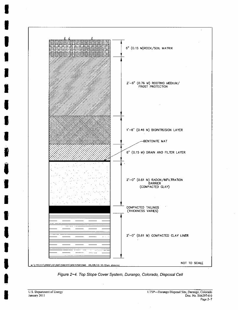
2'-6" (0.76 M) ROOTING MEDIUM/FROST PROTECTION
l'-6" (0.46 M) BIOINTRUSION LAYER
-- BENTONITE MAT
6" (0.15 M) DRAIN AND FILTER LAYER
2'-0" (0.61 M) RADON /INFILTRATIONBARRIER
(COMPACTED CLAY)
COMPACTED TAILINGS(THICKNESS VARIES)
2'-0" (0.61 M) COMPACTED CLAY LINER
NOT TO SCALEU:.TSIl.00.I OOLu i\u iuuw 06081 uo,'uIu U Loi enciol
Figure 2-4. Top Slope Cover System, Durango, Colorado, Disposal Cell
U.S. Department of EnergyJanuary 2011
LTSP-Durango Disposal Site, Durango, ColoradoDoc. No. S06297-0.0
Page 2-7
UP 0C
o En
0 0
01
DO
0
i' , "'
-- - HOLDING POll- -•' ~ eG "EE. -... o'•i- .
.I 2.... -"~ -.---- -..\ 2t
- - - RIPýRAP TYPE C RIPRAP TYPE B-C:
'RIPRAPT7YPEi A fE
- - =7.-~ I• '= ..
ACCESS ROAD- ,, NORTHEAST- " •,.•. " "• "" " -- %\•,SHED. OU TFLOw
- -- - ~~N - DISPOSAL CELL SE UTO
6-ENCH-THIDI ..AXPRAP SLOPE- \ ITC 0
ROCK(/SOIL MATRIXI RI A, \GRASS COVERED "" RIRAP TYP 13••- .. -- • •TP. RP , T a IGRADE BRT E A / \\ w \ -.
i IRPTYPE.C RIRPTYE8 / SM
"" .-- D . E..,'
RRP PR,, " ,-REC<. "\ -.'- "TYI'(/" .. \ " I ,N " "
RRRiPRAP SLOPE- . O L
, " " --... - ---
PROPERTY BOUNDARY
-- l-- DIRECTIONI OF FLOW
CHANGE INI SLOPE ON DISPOSAL CELL
--- "-- ' SLOPE - TRIANGLE POINT S 0OIYSLOPE
ROAD
TELEPHONE LINE
POIERLINE
SCALE III FEET
e, • C -- _ 0. 2 - _ . - RIPRAP TY PE C
~z~~-4 -~~~'-\ ' N~I¶ RIPRAP TYPE 8-C
"- 7. -• DTCH 1O. 2,. . -- - .. 1_ 1 --, " ,-/ ' , . '"SOU TH-x-'..
DITCH TF. ULOVI "
'7 7OURANGO' DISPOSALSITE 13OUIDARY
300 0 X0CIOEETAR IEIIERAL: W0 FEET
600
M: \LTS\EI\000\00000\S660\00 7500.DI55
I:
SE
06/OR/ED lW.0OoiEW~eioi
CAI IiO0 U.S. DEPARTMENT OP (NICT Si o EE
DURANGO. COLORADODISPOSAL SITE
DITE PREPAR.ED , FILCEERoEE6/9/2010 SO5550
Figure 2-5. Embankment Features Durango, Colorado, Disposal Cell
i. no qu C!.. G ow Am
The following major design features will mitigate potential groundwater contamination at thedisposal site:
" A low-permeability liner on the sides and beneath the contaminated tailings (Figure 2-3).
* A compacted clay radon/infiltration barrier (with bentonite mat on top slope and bentoniteamended clay on side slopes) above the tailings material (Figure 2-4).
* A high-conductivity sand drain/filter layer placed on the top of the radon barrier(Figure 2-4).
The low-permeability liner placed underneath the tailings material is composed of natural,recompacted silty clay and clay soils. These soils have high neutralization, adsorption, and ionexchange potential and thus provide a high attenuating capacity to restrict downwardcontaminant migration through the barrier.
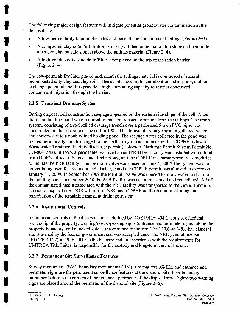
2.2.5 Transient Drainage System
During disposal cell construction, seepage appeared on the eastern side slope of the cell. A toedrain and holding pond were required to manage transient drainage from the tailings. The drainsystem, consisting of a rock-filled drainage trench over a perforated 6-inch PVC pipe, wasconstructed on the east side of the cell in 1989. This transient drainage system gathered waterand conveyed it to a double-lined holding pond. The seepage water collected in the pond wastreated periodically and discharged to the north arroyo in accordance with a CDPHE IndustrialWastewater Treatment Facility discharge permit (Colorado Discharge Permit System Permit No.CO-0041548). In 1995, a permeable reactive barrier (PRB) test facility was installed with a fundfrom DOE's Office of Science and Technology, and the CDPHE discharge permit was modifiedto include the PRB facility. The toe drain valve was closed on June 4, 2004, the system was nolonger being used for treatment and discharge and the CDPHE permit was allowed to expire onJanuary 31, 2009. In September 2009 the toe drain valve was opened to allow water to drain tothe holding pond. In October 2010 the PRB facility was decommissioned and remediated. All ofthe contaminated media associated with the PRB facility was transported to the Grand Junction,Colorado disposal site. DOE will inform NRC and CDPHE on the decommissioning andremediation of the remaining transient drainage system.
2.2.6 Institutional Controls
Institutional controls at the disposal site, as defined by DOE Policy 454.1, consist of federalownership of the property, warning/no-trespassing signs (entrance and perimeter signs) along theproperty boundary, and a locked gate at the entrance to the site. The 120.6-ac (48.8-ha) disposalsite is owned by the federal government and was accepted under the NRC general license(10 CFR 40.27) in 1996. DOE is the licensee and, in accordance with the requirements forUMTRCA Title I sites, is responsible for the custody and long-term care of the site.
2.2.7 Permanent Site Surveillance Features
Survey monuments (SM), boundary monuments (BM), site markers (SMK), and entrance andperimeter signs are the permanent surveillance features at the disposal site. Five boundarymonuments define the corners of the unfenced perimeter of the disposal site. Eighty-two warningsigns are placed around the perimeter of the disposal site (Figure 2-6).
U.S. Department of Energy LTSP-Durango Disposal Site, Durango, ColoradoJanuary 2011 Doc. No. S06297-0.0
Page 2-9
Survey Monuments-SM-i is in the northwest part of the site, SM-2 is south of the disposalcell, and SM-3 and SM-4 are to the east (Table 2-1 and Figure 2-6). The monuments, BerntsenRT- 1 metal markers, were set into the top of a truncated cone of reinforced concrete set inconcrete (DOE 2001).
Boundary Monuments-Five Berntsen federal aluminum survey monuments, Model A-i(DOE 2001), were used for the site boundary monuments (BM-1 through BM-6) (Table 2-1 andFigure 2-6). BM-1, BM-2, and BM-3 mark the northwest, northeast, and southeast comers,respectively, of the site. BM-4 is at the west end of the proposed truncated south boundary, andBM-5 is at the south end of the truncated west boundary, however DOE retained the full area thatis marked by BM-6 in the southwest comer (MK-F 1991).
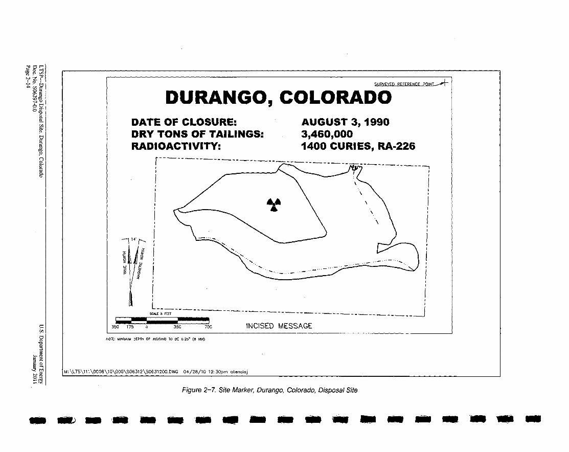
Site Markers-Two unpolished granite site markers (SMK-1 and SMK-2) are within therestricted site boundary. SMK-1 is just inside the entrance gate, and SMK-2 is on top of thedisposal cell revegetated area (DOE 2001). The markers identify the disposal site, the generallocation of the disposal cell, the date of closure (August 3, 1990), the mass of residualradioactive materials (3,460,000 dry tons [3,140,000 tonnes]), and the radioactivity (1,400 curies,radium-226) (Figure 2-7).
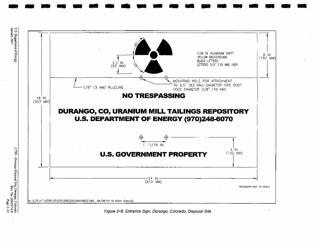
Entrance and Perimeter Signs-The site entrance sign (Figure 2-8) is at the entrance gate. Inaddition to the entrance sign, 82 perimeter signs (Figure 2-9) mark the boundary around most ofthe site (Table 2-1 and Figure 2-6). These signs display the international trefoil symbolindicating the presence of radioactive materials. They also state that the disposal site isU.S. Government property and that trespassing is forbidden. The entrance sign has the sameinformation as the perimeter signs, plus the name of the site and the telephone numbers of DOEand CDPHE offices (Figure 2-8).
Settlement Plates-Fourteen settlement plates (DOE 2001) are located on the disposal cell,primarily on the south and east side slopes of the cell (Table 2-1 and Figure 2-6). The totallong-term settlement of the disposal cell could be measured using the 14 settlement plates. Theplates were installed after the disposal cell was completed.
2.2.8 Site Drawings and Photographs
At the completion of remedial action, disposal site as-built conditions were documented withas-built drawings and photographs (MK-F 1991). This information illustrates baseline conditionsfor comparison to future disposal site conditions.
A disposal site topographic map was prepared and is part of the permanent Durango site file. Thetopographic map, disposal site map drawings, and photographs may be further modified by LM,as necessary. LM is responsible for maintaining and archiving maps, drawings, and photographsin the permanent Durango disposal site file.
LTSP-Durango Disposal Site, Durango, Colorado U.S. Department of EnergyDoc. No. S06297-0.0 January 2011Page 2-10

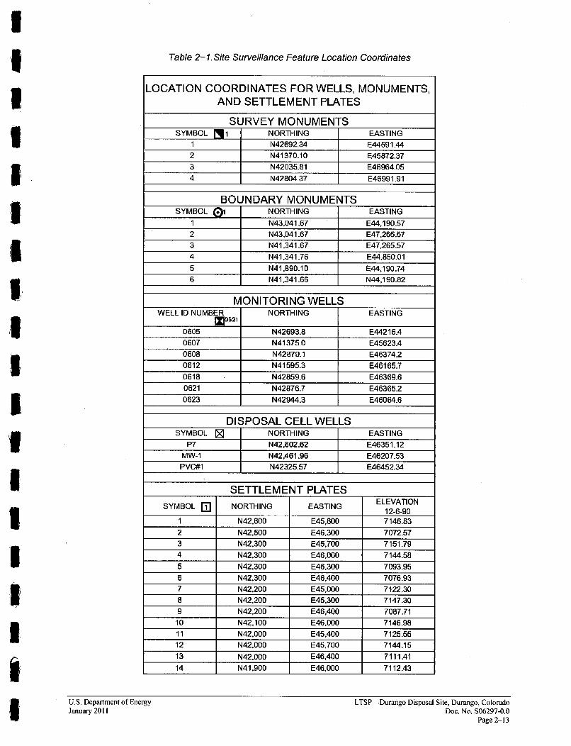
Table 2-1. Site Surveillance Feature Location Coordinates
LOCATION COORDINATES FOR WELLS, MONUMENTS,AND SETTLEMENT PLATES
SURVEY MONUMENTSSYMBOL l 1 NORTHING EASTING
1 N42692.34 E44591.44
2 N41370.10 E45872.37
3 N42035_81 E46964.05
4 N42804137 E46991.91
BOUNDARY MONUMENTSSYMBOL 01 NORTHING EASTING
1 N43,041.67 E44,190.57
2 N43,041.67 E47,265.57
3 N41,341.67 E47,265.57
4 N41,341.76 E44,850.01
5 N41,890.10 E44,190.74
6 N41,341.66 N44,190.82
MONITORING WELLSWELL ID NUMBER NORTHING EASTING
621
0605 N42693.8 E44216A
0607 N41375.0 E45623A
0608 N42879.1 E46374.2
0612 N41595.3 E46165.7
0618 N42859.6 E46369.6
0621 N42876.7 E46365.2
0623 N42944.3 E46064.6
DISPOSAL CELL WELLSSYMBOL Z NORTHING EASTING
P7 N42,602.62 E46351.12
MW-1 N42A61.96 E46207.53
PVG#1 N42325.57 E46452.34
SETTLEMENT PLATESELEVATION
SYMBOL El NORTHING EASTING 12-6-gOL•, 12-6-90
1 NN42,600 E45,800 7146.83
2 N42,500 E46,300 7072.573 N42,300 E45,700 7151.79
4 N42,300 E46,000 7144.58
5 N42,300 E46,300 7093.95
6 N42,300 E46,400 7076.93
7 N42,200 E45,000 7122.30
8 N42,200 E45,300 7147.30
9 N42,200 E46,400 7087.7110 N42,100 E46.000 7146.98
11 N42,000 E45A400 7125.55
12 N42,000 E45,700 7144.15
13 N42,000 E46,400 71111
14 N41,900 E46,000 7112.43
U.S. Department of EnergyJanuary 2011
LTSP-Durango Disposal Site, Durango, ColoradoDoc. No. S06297-0.0
Page 2-13
•0•
0.4o
6c
F
0
SURVEYED REFERENCE POINT - "
DURANGO, COLORADODATE OF CLOSURE: AUGUST 3, 1990DRY TONS OF TAILINGS: 3,460,000RADIOACTIVITY: 1400 CURIES, RA-226
4" 'S.-a
34-1
z
SCALE IN FEET
350 700 INCISED MESSAGE350 175 a
NOTE: MINIMUM DEPTH OF INCISING TO BE 0.25' (6 MM)
M:F\LTS\11\0006\10\000\S0631a2\S631g200.,WG 04/28/10 12:30pm atencioj
Figure 2-7. Site Market, Duran go, Colorado, Disposal Site
lt "a to am 10 - -
m a m S" " a a - At Am Am a m ,.-i m
l- C4
hi
______0.08 IN. ALUMINUM SHEETYELLOW BACKGROUND
2. 5ýIN. BLACK LETTERS(63 MM) 'O , LETTERS 3/4" (19 MM) HIGH
I6 IN.
(152 MM)
L -1/8"MOUNTING HOLE FOR ATTACHMENTTO 2.5" (63 MM)-DIAMETER PIPE POST.
(3 MM) RULELINE HOLE DIAMETER 3/8" (10 MM)
NO TRESPASSING18 IN.(457 MM,
DURANGO, CO, URANIUM MILL TAILINGS REPOSITORYU.S. DEPARTMENT OF ENERGY (970)248-6070
+ +1 11/16 IN.
H
43
2
0
Z
I-CD
* 0'
* 0
U.S. GOVERNMENT PROPERTY4 1IN.
(102 MM)
1• 24 NI -(610 MM)
SCHEMATIC-NOT TO SCALE
M:\LTS\111\0006\10\000\SO6328\SO632800.DWG 06/08/10 10:00cm otencioj
Figure 2-8. Entrance Sign, Durango, Colorado, Disposal Site

CD ~
~o ~Q-.1 0
0
cd~
CD
0
03-0.C
2.5 1 IN.(63 MM)
0 0.08 IN. ALUMINUM SHEETYELLOW BACKGROUNDBLACK LETTERSLETTERS 3/4" (19 MM) HIGH
6 IN.(152 MM)
.,-
L- 1/8" (3
MOUNTING HOLE FOR ATTACHMENTTO 2.5" (63 MM)-DIAMETER PIPE POST.HOLE DIAMETER 3/8" (10 MM)MM) RULELINE
18 IN.(457 MM) URANIUM MILL TAILINGS REPOSITORY
NO TRESPASSINGA4 _44
1 11/16 IN. I
BY ORDER OF THE U.S. DEPARTMENT OF ENERGY (14 IN.MM(1 2 M ,
CJ2
L. CD
0 -'
24 IN.(610 MM)
SCHEMATIC-NOT TO SCALE
M:\LTS\111\OOO6\10\000\SO6313\SO631300.DWG 06/08/10 10:06pm atencioj
Figure 2-9. Perimeter Sign, Durango, Colorado, Disposal Site
s WE M- " so M " w nom am -, M " *w a d a-mel, am
Disposal Site Map
The Durango disposal site map (Figure 2-6) identifies the following site features:
* Disposal site, plus an area of 0 to 1,300 ft (0 to 400 m) around the site boundary
* Topographic features
* Permanent site surveillance features
" Entrance road and gate/barricade
* North and South Side Drainages and Bodo Canyon
* Disposal site boundary
* Disposal cell
* Groundwater monitoring wells
The Durango disposal site map (Figure 2-6) will serve as the base map for site inspections(Section 3.3.5). A new, separate inspection map will be prepared after each inspection. Each siteinspection map will indicate the year and type of inspection.The Durango disposal site base map and site inspection maps will become part of the permanent
Durango disposal site file.
Disposal Site As-Built Drawings
A set of as-built drawings provided by Morrison Knudsen-Ferguson illustrates the final disposalcell construction and final disposal site conditions. These drawings were used to prepare thedisposal site map. They may be used to document changes in physical site conditions or thedisposal cell over time and to develop corrective action plans, if required. These drawings arefiled and maintained in the permanent Durango disposal site file.
Site Baseline and Aerial Photographs
A photographic record of the final site conditions at the Durango disposal site is maintained inthe permanent Durango disposal site file. This record consists of a series of aerial and groundphotographs that provide a baseline visual record of site construction and final site conditions tocomplement the as-built drawings. The post-construction photographs provide an orientation toolfor site inspections and a baseline record of surveillance features. Aerial photographs for thedisposal site were taken throughout remedial action activities from 1987 to 1989 and in 1990 and1991 after surface remedial action was completed. These photographs provide a record of siteconditions, enabling inspectors to monitor changes in site conditions (e.g., erosion patterns,vegetation changes, and land use) over time. The photographs are a useful orientation tool fordisposal site inspections.
U.S. Department of Energy LTSP-Durango Disposal Site, Durango, ColoradoJanuary 2011 Doc. No. S06297-0.0
Page 2-17
2.3 Geology, Hydrology, and Groundwater
2.3.1 Site Geology
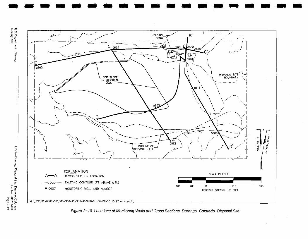
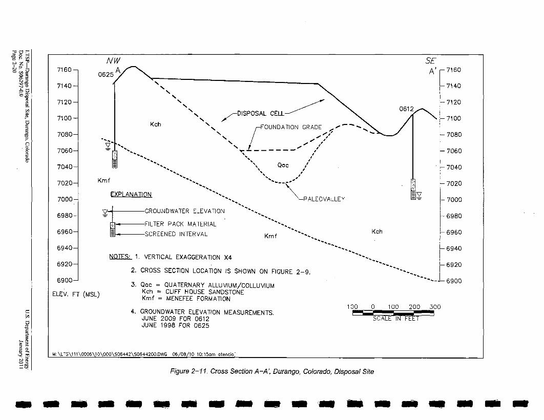
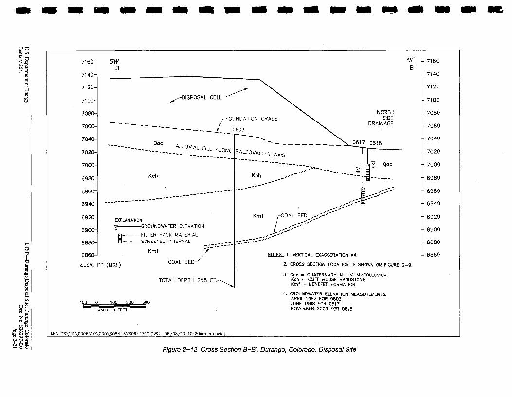
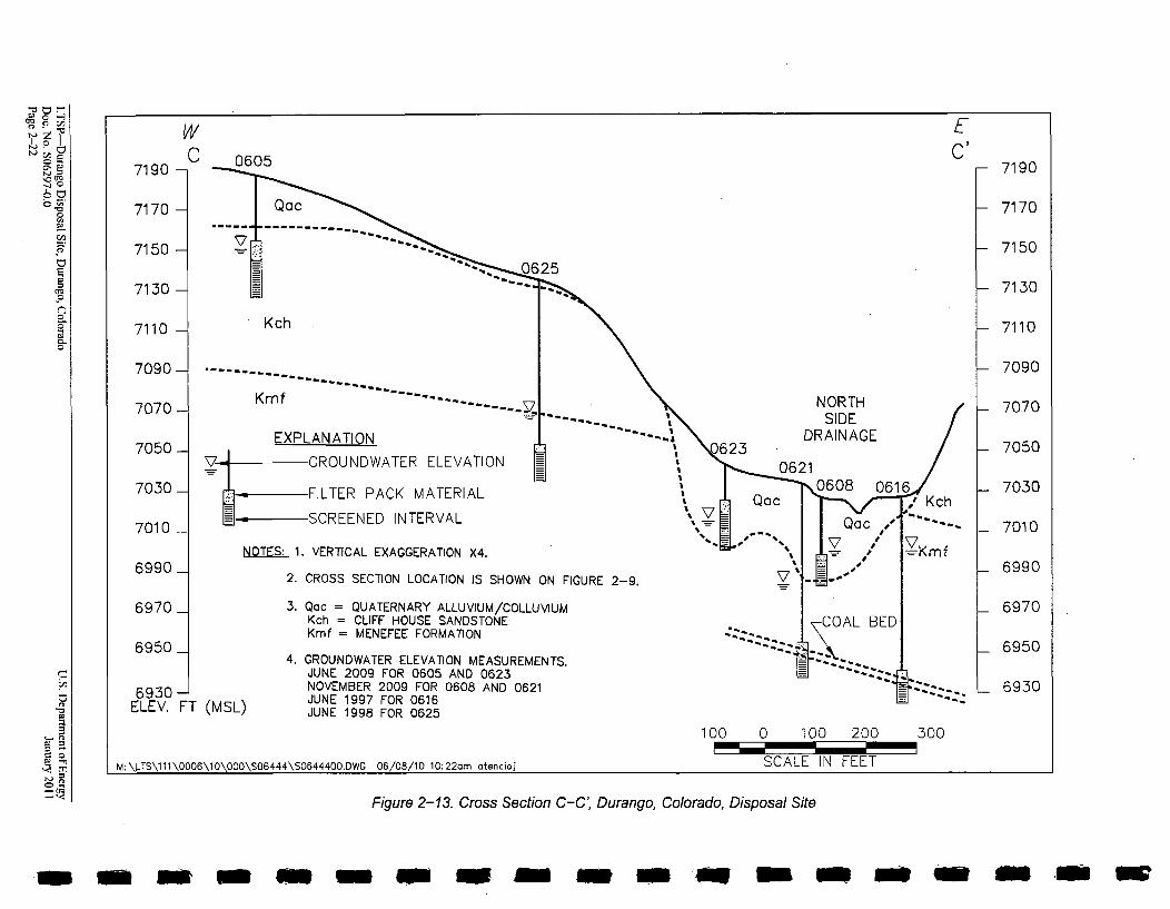
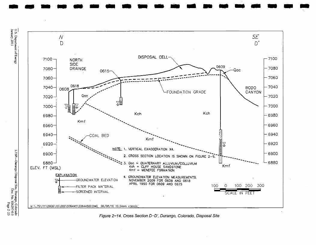
The disposal site is on the east-northeast striking Hogback Monocline, which separates the SanJuan Basin to the southeast from the Four Corners Platform to the northwest. Bedrock dips tothe south-southeast at variable amounts that generally decrease westward across the site, fromabout 13 degrees at the east to about 6 degrees at the west. The locations of four cross sectionsacross the disposal site are shown on Figure 2-10. These cross sections (Figure 2-11 throughFigure 2-14) show the geologic relationships of the dipping bedrock formations and Quaternarymaterial below and adjacent to the disposal cell.
Bedrock underlying the disposal site consists of the upper two (Cliff House Sandstone andMenefee Formation) of three formations that compose the Mesaverde Group. The Cliff HouseSandstone is approximately 400 ft (120 m) thick in this area and consists of an interbeddedsequence of calcareous, yellow-brown sandstone and light-gray mudstone, siltstone, and siltyshale (Kirkham and Navarre 2003). The contact between the Cliff House Sandstone and theunderlying Menefee Formation is a minor disconformity. The Menefee Formation thicknessranges from 225 to 300 ft (70 to 92 m) and consists of interbedded gray, brown, and blackcarbonaceous shale and siltstone; gray, brown, and orange-brown cross-bedded sandstone; andcoal (Kirkham et al. 1999).
Based on lithologic differences, the Cliff House Sandstone may be roughly divided into twoinformal units, lower and upper, which are approximately the same thickness. The lower unitconsists mainly of interbedded siltstone and sandstone beds that range up to 3 ft (1 m) inthickness. The ridge just north of the disposal cell is supported by resistant sandstone beds in thelower unit (Figure 2-11). The upper unit contains more shale beds and fewer and thinnersandstone beds than the lower unit. Less resistant than the lower unit, beds of sandy siltstone inthe upper unit support the ridge just south of the disposal cell (Figure 2-11).
The Menefee Formation is lithologically similar to the overlying Cliff House Sandstone. Themain difference is that the Menefee contains coal beds and carbonaceous material in its shale andsiltstone, making it a more drab color than the Cliff House rocks. A coal bed about 5 ft (1.5 m)thick in the upper part of the Menefee, approximately 80 ft (24 m) below the contact withthe Cliff House Sandstone, occurs beneath the disposal site (Figure 2-12, Figure 2-13, andFigure 2-14). This coal bed was mined in the1890s and 1910s where it crops out about0.1 mile (0.16 km) northeast of the disposal site property in the North Side Drainage(Kirkham et al. 1999). At the disposal site, outcrops of the Menefee Formation (only theuppermost part) are only in the extreme north part along the North Side Drainage.
LTSP-Durango Disposal Site, Durango, Colorado U.S. Department of EnergyDoc. No. S06297-0.0 January 2011Page 2-18
m g --- • m I N g oft
-~~ HOLDING-____ - ____ POND, -__
-D A 0625 0623 0621 D 0608 ./" /" -T
. -. _ K 0616061
I -. 06181/
-1c-i
0
(J~0
0
c-i
* 0
* TQ~ 0
-~ 0~~' o~)
OQ t-,D 0
D.J ~
0~'0 ~ 0
'- 14" ,'
00
EXPLANATIONA-A' CROSS SECTION LOCATION
-7000- EXISTING CONTOUR (FT ABOVE MSL)
* 0607 MONITORING WELL AND NUMBER
M: \LTS\111 \0006\10\000\S06441\S0644100.DWG 06/08/10 10:27am atencioj
SCALE IN FEET
400 200 0 400
CONTOUR INTERVAL: 50 FEET
800
Figure 2-10. Locations of Monitoring Wells and Cross Sections, Durango, Colorado, Disposal Site
.. 0-
~0
.00
0.
0
g"En
0 =
7160-
7140-
7120-
7100-
7080-
7060-
7040-
7020-
7000-
6980-
6960-
6940-
6920-
6900-
ELEV. FT
NW SE
0625 A A'
,,,¢/-DISPOSAL CELL-' 01
Kch NFOUNDATION GRADE --%%Kch-- "-
S /•
%%%i•""".....""• Qoc /t
Kmf EXPLANATION * -7*"
E-PALEOVALLEY
-7160
-7140
-7120
-7100
- 7080
- 7060
- 7040
- 7020
- 7000
- 6980
- 6960
-6940
-6920
- 6900
GROUNDWATER ELEVATION -* *
FILTER PACK MATERIAL ..
-SCREENED INTERVAL Kmf
NOTES: 1. VERTICAL EXAGGERATION X4
2. CROSS SECTION LOCATION IS SHOWN ON FIGURE 2-9.
3. Qoc = QUATERNARY ALLUVIUM/COLLUVIUMKch CLIFF HOUSE SANDSTONEKmf = MENEFEE FORMATION
4. GROUNDWATER ELEVATION MEASUREMENTS.JUNE 2009 FOR 0612JUNE 1998 FOR 0625
Kch
(MSL)
100 0 100 200 300
SCALE IN FEET
M:\LTS\111\0006\10\000\S06442\SO644200.DWG 06/08/10 10:15am atencioj
Figure 2-11. Cross Section A-A', Durango, Colorado, Disposal Site
Am - m I m w Am no 'm mw OW m 0- m so --
ýmtmm -m f m to of an M If so m so= moa
0
C20
r, 0
C) a~r
7160-
7140-
7120-
7100-
7080-
7060-
7040-
7020-
7000-
6980-
6960-
6940-
6920-
6900-
6880
686
ELEV. FT (I
SWB
,.--DISPOSALCE --
NORTH. FUNDATION GRADEI SIDE
063 .DRAINAGE
-oa -" --- 0617 0618. ALLUVIAL FILL ALONG PALEOVALLEY AXIS
Kch Kch , -" . . . - .
- - - - - - - - -- --------- --
------------
Kmf COAL BED:-.- -
EXPLANATION
ROUNDWATER ELEVATION -
J- -FILTER PACK MATERIAL -- -- --
-- SCREENED INTERVAL .....
Kmf C LNOTES: 1. VERTICAL EXAGGERATION X4.
MSL) 2. CROSS SECTION LOCATION IS SHOWN ON FIGURE 2
3. QOac = QUATERNARY ALLUVIUM/COLLUVIUMTOTAL DEPTH 255 FT. Kch= CLIFF HOUSE SANDSTONE
Kmf = MENEFEE FORMATION
NEB'
- 7160
- 7140
- 7120
- 7100
- 7080
- 7060
- 7040
- 7020
7000
7 6980
-6960
- 6940
6920
6900
- 6880
- 6860
~-9.
4. GROUNDWATER ELEVATION MEASUREMENTS.APRIL 1987 FOR 0603JUNE 1998 FOR 0617NOVEMBER 2009 FOR 0618
100 0 100 200 300
SCALE IN FEET
M: \LTS\1 11 \0006\1 0\000\S06443\S0644300.DWG 06/08/10 1 0:20am atencioj
Figure 2-12. Cross Section B-B', Durango, Colorado, Disposal Site
C/)
6o
EL
C'
0
wC
EC ',
nAnvs7190-
7170 -
7150
7130 -
7110 -
7090-
7070-
7050-
7030-
7010 _
6990_
6970_
6950_
6930-ELEV. FT (MSL
7
i
zz 625
Kch
Kmf -.. ... . .
EXPLANATION
GROUNDWATER ELEVATION623
NORTHSIDE
DRAINAGE
- 7190
- 7170
- 7150
- 7130
- 7110
- 7090
7070
- 7050
- 7030
- 7010
- 6990
6970
- 6950
t__ 6930
LTER PACK MATERIAL
-SCREENED INTERVALKch
NOTES: 1. VERTICAL EXAGGERATION X4.
2. CROSS SECTION LOCATION IS SHOWN ON FIGURE 2-9.
3. Qoc QUATERNARY ALLUVIUM/COLLUVIUMKch CLIFF HOUSE SANDSTONEKmf MENEFEE FORMATION
4. GROUNDWATER ELEVATION MEASUREMENTS.JUNE 2009 FOR 0605 AND 0623NOVEMBER 2009 FOR 0608 AND 0621JUNE 1997 FOR 0616JUNE 1998 FOR 0625
17.-mf
100 0 100 200 300
SCALE IN FEETM:\ýTS'\111\0006\10\000\S06444\SO644400.DWG 06/08/10 10:22am atenciol
Figure 2-13. Cross Section C-C, Durango, Colorado, Disposal Site
moom 8WIM"m swim m'"w:4w mgo we Aw m lwm Im
am -w M mm No Jf s ,m Mu
0
mCD
C
0
~ 0~0 0~w o~flID tj o
I~I.U~ C 0
ND
SED P
7100- NORTHSIDE
7080- DRAINGE 0615
7060-
7040- 0618
7 060- 8. •"
7020- Qac,,"
7000- • V / .
6980- Kf"
Kmf6960-
6940- -COAL BED
6920-..5. NOT
6900-
6880-FT (MSL)
EXPLANATIONGROUNDWATER ELEVATION
FILTER PACK MATERIAL
L- SCREENED INTERVAL
BODOCANYONGRADE
-7100
-7080
-7060
-7040
-7020
- 7000
- 6980
-6960
- 6940
-6920
-6900
-6880
Kch Kch
-2;---..Kmf-.----
E: 1. VERTICAL EXAGGERATION X4. - *-,
2. CROSS SECTION LOCATION IS SHOWN ON FIGURE 2-9."
ZZ 3. Qac QUATERNARY ALLUVIUM/COLLUVIUMKch = CLIFF HOUSE SANDSTONEKmf = MENEFEE FORMATION
4. GROUNDWATER ELEVATION MEASUREMENTS.NOVEMBER 2009 FOR 0608 AND 0618APRIL 1990 FOR 0609 AND 0615
KmfELEV.
IU 0 100 200 300
SCALE IN FEET
MI:\LTS,\111\0006\10\000\SO6445\SO644500.DWG 06/08/10 10:24om atencioj
Figure 2-14. Cross Section D-D', Durango, Colorado, Disposal Site
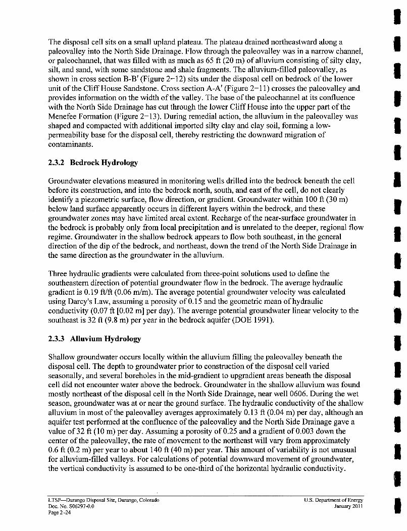
!The disposal cell sits on a small upland plateau. The plateau drained northeastward along apaleovalley into the North Side Drainage. Flow through the paleovalley was in a narrow channel,or paleochannel, that was filled with as much as 65 ft (20 m) of alluvium consisting of silty clay,silt, and sand, with some sandstone and shale fragments. The alluvium-filled paleovalley, asshown in cross section B-B' (Figure 2-12) sits under the disposal cell on bedrock of the lowerunit of the Cliff House Sandstone. Cross section A-A' (Figure 2-11) crosses the paleovalley andprovides information on the width of the valley. The base of the paleochannel at its confluencewith the North Side Drainage has cut through the lower Cliff House into the upper part of theMenefee Formation (Figure 2-13). During remedial action, the alluvium in the paleovalley wasshaped and compacted with additional imported silty clay and clay soil, forning a low-permeability base for the disposal cell, thereby restricting the downward migration of
contaminants.
2.3.2 Bedrock Hydrology
Groundwater elevations measured in monitoring wells drilled into the bedrock beneath the cellbefore its construction, and into the bedrock north, south, and east of the cell, do not clearlyidentify a piezometric surface, flow direction, or gradient. Groundwater within 100 ft (30 m)below land surface apparently occurs in different layers within the bedrock, and thesegroundwater zones may have limited areal extent. Recharge of the near-surface groundwater inthe bedrock is probably only from local precipitation and is unrelated to the deeper, regional flowregime. Groundwater in the shallow bedrock appears to flow both southeast, in the generaldirection of the dip of the bedrock, and northeast, down the trend of the North Side Drainage inthe same direction as the groundwater in the alluvium.
Three hydraulic gradients were calculated from three-point solutions used to define thesoutheastern direction of potential groundwater flow in the bedrock. The average hydraulicgradient is 0.19 ft/ft (0.06 m/m). The average potential groundwater velocity was calculatedusing Darcy's Law, assuming a porosity of 0.15 and the geometric mean of hydraulicconductivity (0.07 ft [0.02 m] per day). The average potential groundwater linear velocity to thesoutheast is 32 ft (9.8 in) per year in the bedrock aquifer (DOE 1991).
2.3.3 Alluvium Hydrology
Shallow groundwater occurs locally within the alluvium filling the paleovalley beneath thedisposal cell. The depth to groundwater prior to construction of the disposal cell variedseasonally, and several boreholes in the mid-gradient to upgradient areas beneath the disposalcell did not encounter water above the bedrock. Groundwater in the shallow alluvium was foundmostly northeast of the disposal cell in the North Side Drainage, near well 0606. During the wetseason, groundwater was at or near the ground surface. The hydraulic conductivity of the shallowalluvium in most of the paleovalley averages approximately 0.13 ft (0.04 m) per day, although anaquifer test performed at the confluence of the paleovalley and the North Side Drainage gave avalue of 32 ft (10 m) per day. Assuming a porosity of 0.25 and a gradient of 0.003 down thecenter of the paleovalley, the rate of movement to the northeast will vary from approximately0.6 ft (0.2 in) per year to about 140 ft (40 m) per year. This amount of variability is not unusualfor alluvium-filled valleys. For calculations of potential downward movement of groundwater,the vertical conductivity is assumed to be one-third of the horizontal hydraulic conductivity.
LTSP-Durango Disposal Site, Durango, Colorado U.S. Department of EnergyDoc. No. S06297-0.0 January 2011Page 2-24

2.3.4 Background Groundwater Quality
Because of the limited area of alluvial system saturation under natural conditions beneath thedisposal cell (confined to the paleovalley), the bedrock aquifer (also called the CliffHouse/Menefee aquifer) is considered the uppermost aquifer at the Durango disposal site(DOE 1991).
Background groundwater quality in the bedrock aquifer has been determined from samples from10 monitoring wells completed in the bedrock aquifer (Table 2-2). These wells are located bothupgradient and downgradient of the disposal cell. Data collected from 1987 through 1994 wereused to characterize background water quality (DOE 1996). Data collected since that time fromone bedrock background well has been consistent with this data set and has been reported inTitle I Annual Reports. These reports are available to the public on the LM website.
Background groundwater quality in the bedrock aquifer varies between wells, primarily becausethe amount of dissolved sulfate salts varies between wells. These salts are thought to be derivedfrom the dissolution of natural gypsum in the aquifer. Total dissolved solids range from 932 to7,440 milligrams per liter (mg/L). Major anions include sulfate and/or bicarbonate. Sodium isgenerally the major cation. The groundwater is generally oxidizing; however, measuredoxidation-reduction potentials vary in individual wells from reducing (-353 millivolts [mV]) tooxidizing (768 mV). Groundwater pH in the bedrock aquifer also ranges from alkaline (averagepH of 8.9 in well 0609) to acidic (average pH of 4.9 in well 0621). The acidic water in well 0621and in adjacent well 0616 is thought to be due to the natural oxidation of pyrite (iron sulfide) inthe aquifer. The naturally acidic water is associated with high amounts of dissolved iron (asmuch as 452 mg/L), manganese (as much as 6.04 mg/L), sulfate (as much as 4,000 mg/L), andsulfide (as much as 16 mg/L). Trace constituents that have been detected at least once inbackground samples include antimony, arsenic, beryllium, cadmium, chromium, lead, mercury,molybdenum, nickel, radium-226, radium-228, selenium, silver, thallium, uranium, andvanadium (Table 2-2).
The variation in background water quality within the bedrock aquifer probably reflects localvariations in lithology and perhaps changes in oxidation-reduction conditions related to thenatural movement of dissolved oxygen and groundwater through the aquifer. It is possible thatchanges in water quality in individual wells will occur in response to future natural variations ingroundwater flow and oxidation-reduction conditions. To reduce the chance that future naturallyoccurring variation will be mistaken for contamination from the disposal cell, a single broaddefinition of background water quality has been developed. This definition combines all datafrom sampled bedrock wells in the disposal cell area.
U.S. Department of Energy LTSP-Durango Disposal Site, Durango, ColoradoJanuary 2011 Doe. No. S06297-0.0
Page 2-25
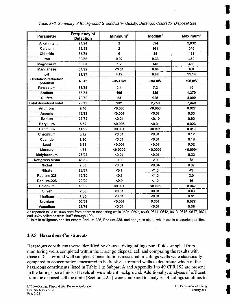
Table 2-2. Summary of Background Groundwater Quality, Durango, Colorado, Disposal Site
Parameter Frequency of Minimuma Mediana MaximumaDetection
Alkalinity 94194 2 694 2,032
Calcium 88188 2 161 545
Chloride 85185 6 36 428
Iron 80/88 0.02 0.33 452
Magnesium 88188 1.2 143 458
Manganese 84192 <0.01 0.06 6.0
pH 97197 4.72 6.88 11.14
Oxidation-reductio 43/43 -353 mV 204 mV 768 mVpotential
Potassium 88/88 3.4 7.2 40
Sodium 88/88 105 336 1,370
Sulfate 79/79 23 925 4,000
Total dissolved solid 79/79 932 2,750 7,440
Antimony 9/46 <0.003 <0.003 0.027
Arsenic 12/92 <0.001 <0.01 0.03
Barium 27/72 <0.01 <0.10 0.90
Beryllium 5152 <0.005 <0.01 0.023
Cadmium 14/92 <0.001 <0.001 0.019
Chromium 6/72 <0.01 <0.01 0.12
Cyanide 1/30 <0.01 <0.01 0.18
Lead 9/88 <0.001 <0.01 0.02
Mercury 4/68 <0.0002 <0.0002 <0.0004
Molybdenum 25/92 <0.01 <0.01 0.22
Net gross alpha 48/82 0.0 2.9 35
Nickel 7158 <0.01 <0.04 0.07
Nitrate 28/87 <0.1 <1.0 43
Radium-226 12/90 <0.1 <1.0 2.0
Radium-228 20/90 <0.9 <1.0 15
Selenium 18/92 <0.001 <0.005 0.042
Silver 2/68 <0.01 <0.01 0.03
Thallium 1135 <0.01 <0.01 0.01
Uranium 53/89 <0.001 0.001 0.077
Vanadium 27/79 <0.01 <0.01 0.06
As reported in DOE 1996 data from bedrock monitoring wells 0605, 0607, 0609, 0611, 0612, 0613, 0616, 0617, 0621,and 0625 collected from 1987 through 1994.a Units in milligrams per liter except Radium-226, Radium-228, and net gross alpha, which are in picocuries per liter.
2.3.5 Hazardous Constituents
Hazardous constituents were identified by characterizing tailings pore fluids sampled frommonitoring wells completed within the Durango disposal cell and comparing the results withthose of background well samples. Concentrations measured in tailings wells were statisticallycompared to concentrations measured in bedrock background wells to determine which of thehazardous constituents listed in Table 1 to Subpart A and Appendix I to 40 CFR 192 are presentin the tailings pore fluids at levels above ambient background. Additionally, analyses of effluentfrom the disposal cell toe drain (Section 2.2.5) were compared to analyses of tailings solutions to
I£IIIIIIIIIIIIIIIi*
ILTSP-Durango Disposal Site, Durango, ColoradoDoc. No. S06297-0.0Page 2-26
U.S. Department of EnergyJanuary 2011

provide further information about the levels of hazardous constituents derived from the tailings.In general, the toe drain results and disposal cell well results were in agreement. Concentrationsof arsenic, cadmium, molybdenum, radium-226, selenium, uranium, and vanadium weresignificantly elevated in tailings pore fluids, the median concentration from tailings pore fluidsexceeded the median background level by at least 1 order of magnitude.
A second group of hazardous constituents, including beryllium, chromium, mercury, nickel, andsilver, were found to be statistically elevated in tailings pore solution compared to background,although in more than half the tailings samples, they were below detection limits. Furthermore,the detected concentrations from tailings solutions were not remarkably higher than the detectionlimits or than observed background levels. The statistical significance of these constituents isattributable primarily to their greater frequency of detection in tailings samples than inbackground samples. These constituents were retained as hazardous constituents at the Durangodisposal site but are not expected to be reliable indicators of potential groundwatercontamination, because they occur infrequently in the tailings solutions and are below detectionlimits in the toe drain effluent. They occur at levels near background and likely will beattenuated by reactions with the clay liner and alluvial material. These reactions will reduceconcentrations to background levels before the bedrock aquifer is reached.
Several constituents listed in Table A or Appendix I of 40 CFR 192 either were not detected inthe tailings or toe drain effluent (antimony, barium, cyanide, net gross alpha, and thallium) oroccurred at levels equal to or less than levels found in background groundwater based onstatistical testing (lead, nitrate, and radium-228). These constituents are not designated ashazardous constituents at the Durango disposal site.
2.3.6 Concentration Limits for Hazardous Constituents
Concentration limits in point-of-compliance (POC) wells for long-term monitoring of thedisposal cell (Table 2-3) were established following EPA guidance (EPA 1992). In thisguidance, EPA endorsed the use of tolerance intervals for detecting contamination abovebackground in one or more downgradient wells. Updated guidance (EPA 2009) is consistent withthis earlier recommendation. A tolerance interval is designed to contain all but a smallpercentage of future measurements from wells accessing uncontaminated water. Therefore,repeated exceedances of the upper tolerance limit present statistical evidence of contamination.
Because of inherent uncertainties at the Durango disposal site concerning the geographic andstatistical distribution of naturally occurring constituents in the groundwater, a nonparametricapproach was used to determine a tolerance interval for the hazardous constituents. The uppertolerance limit is the maximum observed concentration in bedrock well samples collectedbetween 1987 and 1994. At the Durango site, the maximum concentrations are based onanalytical results ranging from 52 measurements for beryllium to as many as 92 measurementsfor cadmium, chromium, and selenium. There is 95 percent confidence that the maximumobserved concentration of each constituent represents a level that will exceed background nomore than 5 percent of the time. Therefore, using the maximum observed concentration as aconcentration limit for long-term groundwater monitoring produces reasonable protection againstfalse positive results from random background variation.
U.S. Department of Energy LTSP-Durango Disposal Site, Durango, ColoradoJanuary 2011 Doe. No. S06297-0.0
Page 2-27
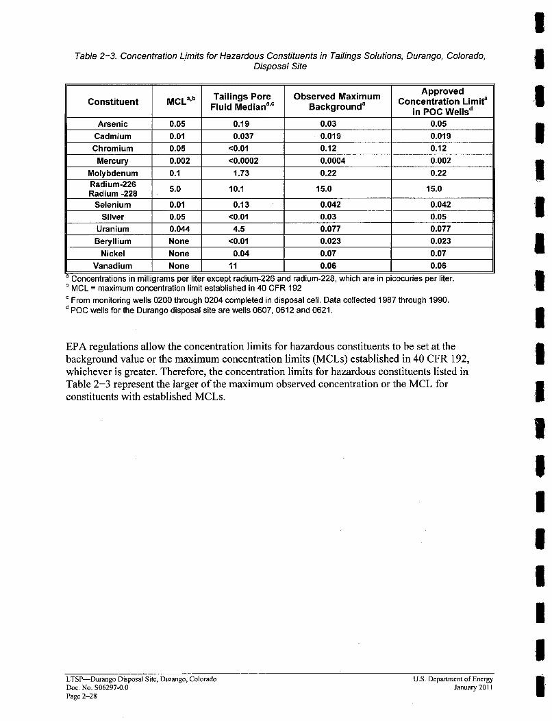
Table 2-3. Concentration Limits for Hazardous Constituents in Tailings Solutions, Durango, Colorado,Disposal Site
ApprovedConstituentTailings Pore Observed Maximum Concentration Limita
Fluid Mediana'c Backgrounda in POC Wellsd
Arsenic 0.05 0.19 0.03 0.05Cadmium 0.01 0.037 0.019 0.019Chromium 0.05 <0.01 0.12 0.12
Mercury 0.002 <0.0002 0.0004 0.002Molybdenum 0.1 1.73 0.22 0.22Radium-226Radium-228 5.0 10.1 15.0 15.0Radium -228
Selenium 0.01 0.13 0.042 0.042Silver 0.05 <0.01 0.03 0.05
Uranium 0.044 4.5 0.077 0.077Beryllium None <0.01 0.023 0.023
Nickel None 0.04 0.07 0.07Vanadium None 11 0.06 0.06
a Concentrations in milligrams per liter except radium-226 and radium-228, which are in picocuries per liter.b MCL = maximum concentration limit established in 40 CFR 192c From monitoring wells 0200 through 0204 completed in disposal cell. Data collected 1987 through 1990.d POC wells for the Durango disposal site are wells 0607, 0612 and 0621.
EPA regulations allow the concentration limits for hazardous constituents to be set at thebackground value or the maximum concentration limits (MCLs) established in 40 CFR 192,
whichever is greater. Therefore, the concentration limits for hazardous constituents listed inTable 2-3 represent the larger of the maximum observed concentration or the MCL for
constituents with established MCLs.
IIIIIIIIIIII5IIIIIILTSP-Durango Disposal Site, Durango, Colorado
Doc. No. S06297-0.0Page 2-28
U.S. Department of EnergyJanuary 2011
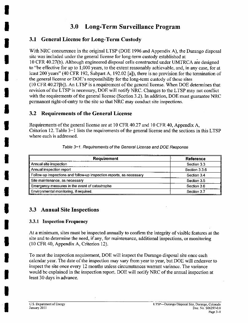
3.0 Long-Term Surveillance Program
3.1 General License for Long-Term Custody
With NRC concurrence in the original LTSP (DOE 1996 and Appendix A), the Durango disposalsite was included under the general license for long-term custody established at10 CFR 40.27(b). Although engineered disposal cells constructed under UMTRCA are designedto "be effective for up to 1,000 years, to the extent reasonably achievable, and, in any case, for atleast 200years" (40 CFR 192, Subpart A, 192.02 [a]), there is no provision for the termination ofthe general license or DOE's responsibility for the long-term custody of these sites(10 CFR 40.27[b]). An LTSP is a requirement of the general license. When DOE determines thatrevision of the LTSP is necessary, DOE will notify NRC. Changes to the LTSP may not conflictwith the requirements of the general license (Section 3.2). In addition, DOE must guarantee NRCpermanent right-of-entry to the site so that NRC may conduct site inspections.
3.2 Requirements of the General License
Requirements of the general license are at 10 CFR 40.27 and 10 CFR 40, Appendix A,Criterion 12. Table 3-1 lists the requirements of the general license and the sections in this LTSPwhere each is addressed.
Table 3-1. Requirements of the General License and DOE Response
Requirement ReferenceAnnual site inspection Section 3.3Annual inspection report Section 3.3.6Follow-up inspections and follow-up inspection reports, as necessary Section 3.4Site maintenance, as necessary Section 3.5Emergency measures in the event of catastrophe Section 3.6Environmental monitoring, if required. Section 3.7
3.3 Annual Site Inspections
3.3.1 Inspection Frequency
At a minimum, sites must be inspected annually to confirm the integrity of visible features at thesite and to determine the need, if any, for maintenance, additional inspections, or monitoring(10 CFR 40, Appendix A, Criterion 12).
To meet the inspection requirement, DOE will inspect the Durango disposal site once eachcalendar year. The date of the inspection may vary from year to year, but DOE will endeavor toinspect the site once every 12 months unless circumstances warrant variance. The variancewould be explained in the inspection report. DOE will notify NRC of the annual inspection atleast 30 days in advance.
U.S. Department of Energy LTSP-Durango Disposal Site, Durango, ColoradoJanuary 2011 Doe. No. S06297-0.0
Page 3-1
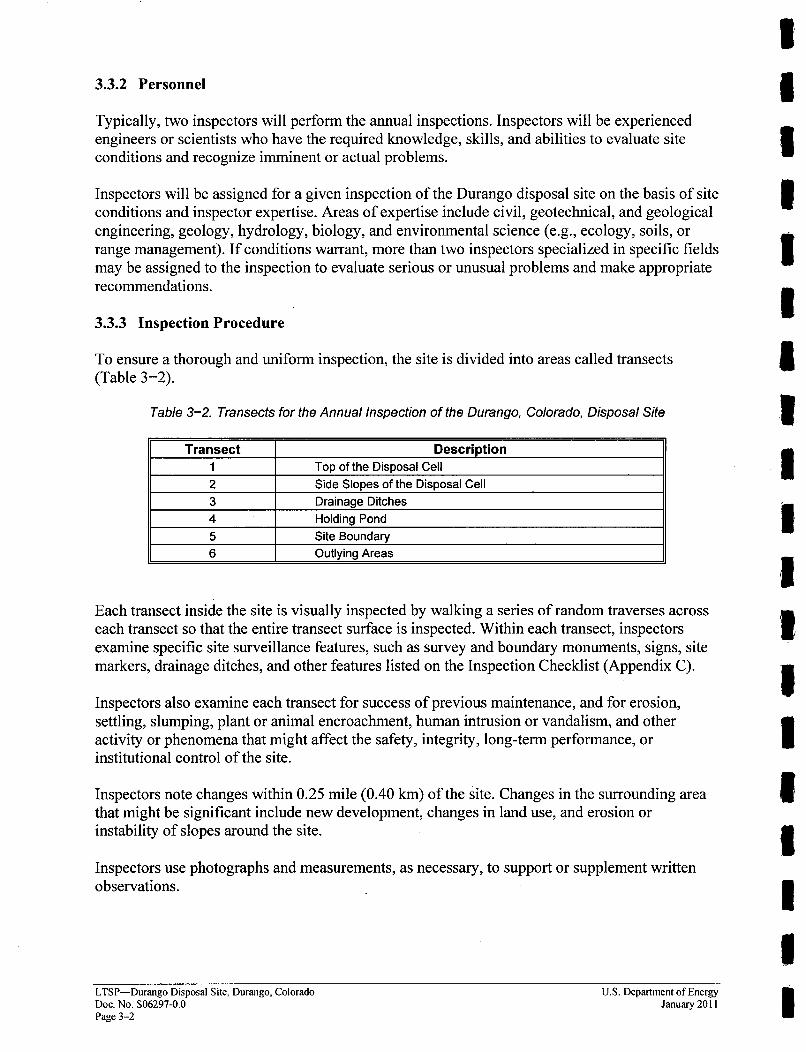
3.3.2 Personnel
Typically, two inspectors will perform the annual inspections. Inspectors will be experiencedengineers or scientists who have the required knowledge, skills, and abilities to evaluate siteconditions and recognize imminent or actual problems.
Inspectors will be assigned for a given inspection of the Durango disposal site on the basis of siteconditions and inspector expertise. Areas of expertise include civil, geotechnical, and geologicalengineering, geology, hydrology, biology, and environmental science (e.g., ecology, soils, orrange management). If conditions warrant, more than two inspectors specialized in specific fieldsmay be assigned to the inspection to evaluate serious or unusual problems and make appropriaterecommendations.
3.3.3 Inspection Procedure
To ensure a thorough and uniform inspection, the site is divided into areas called transects(Table 3-2).
Table 3-2. Transects for the Annual Inspection of the Durango, Colorado, Disposal Site
Transect Description1 Top of the Disposal Cell2 Side Slopes of the Disposal Cell3 Drainage Ditches4 Holding Pond5 Site Boundary6 Outlying Areas
Each transect inside the site is visually inspected by walking a series of random traverses acrosseach transect so that the entire transect surface is inspected. Within each transect, inspectorsexamine specific site surveillance features, such as survey and boundary monuments, signs, sitemarkers, drainage ditches, and other features listed on the Inspection Checklist (Appendix C).
Inspectors also examine each transect for success of previous maintenance, and for erosion,settling, slumping, plant or animal encroachment, human intrusion or vandalism, and otheractivity or phenomena that might affect the safety, integrity, long-term performance, orinstitutional control of the site.
Inspectors note changes within 0.25 mile (0.40 km) of the site. Changes in the surrounding areathat might be significant include new development, changes in land use, and erosion orinstability of slopes around the site.
Inspectors use photographs and measurements, as necessary, to support or supplement writtenobservations.
IIIIIIIIIUIIIUIIIUILTSP-Durango Disposal Site, Durango, Colorado
Doec. No. S06297-0.0Page 3-2
U.S. Department of EnergyJanuary 2011
3.3.4 Inspection Checklist
Inspectors are briefed, and the inspection checklist is reviewed before the annual inspection.A sample checklist is provided in Appendix C.
The checklist includes
* Specific site surveillance features to be inspected;
* Routine observations to be made; and
* Special issues or problems, if any, to be observed and evaluated.
The checklist is reviewed annually and revised as necessary to reflect changes or new conditionsat the site.
3.3.5 Site Inspection Map
A new site inspection map will be prepared after each annual inspection using the disposal sitemap (Figure 2-6) as a base. This map will include at a minimum the following:
* Photograph locations;
* Locations and descriptions of new, anomalous, or unexpected features;
* Features identified during previous inspections for observation or monitoring; and
* Inspection date.
3.3.6 Annual Inspection Report
DOE will report results of the annual inspection to NRC within 90 days of the last Title I siteinspection in the calendar year (10 CFR 40, Appendix A, Criterion 12). If the report cannot besubmitted in accordance with 10 CFR 40, DOE will notify NRC. Annual reports are madeavailable to the public and other agencies.
3.4 Follow-up Inspections
Follow-up inspections are unscheduled inspections that are conducted in response to threateningor unusual site conditions.
3.4.1 Criteria for Follow-Up Inspections
* Criteria for follow-up inspections are found at 10 CFR 40.27(b)(4). DOE will conduct a follow-up inspection when:
A condition is identified during the annual inspection (or other site visit) that requirespersonnel, perhaps with specific expertise, to return to the site to evaluate the condition; or
DOE is notified by a citizen or outside agency that conditions at the site are substantiallychanged.
The public may use the 24-hour DOE telephone number posted on the entrance sign to requestinformation or to report a problem at the site (Figure 2-8).
U.S. Department of Energy LTSP-Durango Disposal Site, Durango, ColoradoJanuary 2011 Doc. No. S06297-0.0
Page 3-3
Once a new or changed condition is identified, DOE will evaluate the information and determinewhether a follow-up inspection is warranted. Conditions that may require a follow-up inspection
include changes in vegetation, erosion, storm damage, wildfires, low-impact human intrusion,vandalism, elevated concentrations of analytes in groundwater, or the need to evaluate, design, orperform maintenance projects. Conditions that threaten the safety of the site or the integrity ofthe disposal cell may require a more urgent follow-up inspection or emergency response. Slopefailure, severe storm, major seismic event, and deliberate human intrusion are among theseconditions. DOE may request the assistance of local agencies to confirm the seriousness of acondition before conducting a follow-up inspection or emergency response (Section 3.5).
DOE will use a graded approach with respect to follow-up inspections. Urgency will beproportional to the potential seriousness of the condition. For example, a follow-up inspectionto investigate or control vegetation may be postponed until a particular time during thegrowing season.
In the event of "unusual damage or disruption" (10 CFR 40, Appendix A, Criterion 12), damagethat may compromise or threaten the safety, security, or integrity of the site, DOE will:
" Notify NRC pursuant to 10 CFR 40, Appendix A, Criterion 12, or 10 CFR 40.60,whichever applies.
* Begin the DOE internal occurrence notification process (DOE Order 231. 1A).
" Respond with an immediate follow-up inspection or emergency response team.
" Implement emergency measures, as necessary, to prevent or contain exposure or release ofradioactive materials (Section 3.5).
3.4.2 Personnel
DOE will assign inspectors to follow-up inspections on the same basis as the annual siteinspection (see Section 3.3.2).
3.4.3 Reports
Results of follow-up inspections for incidents or conditions that do not threaten disposal cellintegrity will be included in the annual inspection report to NRC. Separate reports will not beissued unless DOE determines that is it advisable to notify NRC and other agencies of apotentially serious problem at the site.
If follow-up inspections are required for more urgent reasons, DOE will submit a preliminaryreport of the follow-up inspection to NRC within the 60-day period required by 10 CFR 40,Appendix A, Criterion 12.
3.4.4 Beneficial Reuse Inspections
The need for additional inspections may be required if any type of reuse activities are initiated, toensure that reuse of the site does not interfere with the site integrity or protectiveness. DOEwould increase the frequency of site inspections from yearly to monthly as well as additionalinspections following severe rainfall events, to ensure that potential erosion or any other negativeimpacts are identified and remedied before they become significant. Less frequent inspectionsmay be approved as appropriate. These inspections will be conducted following the annual site
LTSP-Durango Disposal Site, Durango, Colorado U.S. Department of EnergyDoc. No. S06297-0.0 January 2011Page 3--4
inspection procedure with focus on the added site features and issues associated with the reuseactivities including evaluating the condition of the diversion channels to ensure that they remainfunctional as engineered.
3.5 Routine Site Maintenance and Emergency Measures
Emergency response is action DOE will take in response to "unusual damage or disruption" thatthreatens or compromises site safety, security, or integrity (10 CFR 40, Appendix A,Criterion 12).
3.5.1 Criteria for Routine Site Maintenance and Emergency Measures
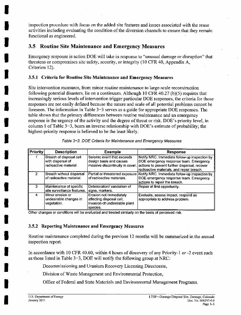
Site intervention measures, from minor routine maintenance to large-scale reconstructionfollowing potential disasters, lie on a continuum. Although 10 CFR 40.27 (b)(5) requires thatincreasingly serious levels of intervention trigger particular DOE responses, the criteria for thoseresponses are not easily defined because the nature and scale of all potential problems cannot beforeseen. The information in Table 3-3 serves as a guide for appropriate DOE responses. Thetable shows that the primary differences between routine maintenance and an emergencyresponse is the urgency of the activity and the degree of threat or risk. DOE's priority level, incolumn 1 of Table 3-3, bears an inverse relationship with DOE's estimate of probability; thehighest-priority response is believed to be the least likely.
Table 3-3. DOE Criteria for Maintenance and Emergency Measures
Priority Description Example Response1 Breach of disposal cell Seismic event that exceeds Notify NRC. Immediate follow-up inspection by
with dispersal of design basis and causes DOE emergency response team. Emergencyradioactive material, massive discontinuity in cover, actions to prevent further dispersal, recover
____________________radioactive materials, and repair breach.2 Breach without dispersal Partial or threatened exposure Notify NRC. Immediate follow-up inspection by,
of radioactive material, of radioactive materials. DOE emergency response team. Emergency____________________actions to repair the breach.
3 Maintenance of specific Deterioration/ vandalism of Repair at first opportunity.site surveillance features. signs, markers._____________________
4 Minor erosion or Erosion not immediately Evaluate, assess impact, respond asundesirable changes in affecting disposal cell, appropriate to address problem.vegetation, invasion of undesirable plant
________________________ I species.
Other changes or conditions will be evaluated and treated similarly on the basis of perceived risk.
3.5.2 Reporting Maintenance and Emergency Measures
Routine maintenance completed during the previous 12 months will be summarized in the annualinspection report.
In accordance with 10 CFR 40.60, within 4 hours of discovery of any Priority- I or -2 event suchas those listed in Table 3-3, DOE will notify the following group at NRC:
Decommissioning and Uranium Recovery Licensing Directorate,
Division of Waste Management and Environmental Protection,
Office of Federal and State Materials and Environmental Management Programs.
U.S. Department of Energy LTSP-Durango Disposal Site, Durango, ColoradoJanuary 2011 Doe. No. S06297-0.0
Page 3-5
The phone number for the required 4-hour contact to the NRC Operations Center is(301) 816-5100.
3.6 Environmental Monitoring
3.6.1 Groundwater Monitoring
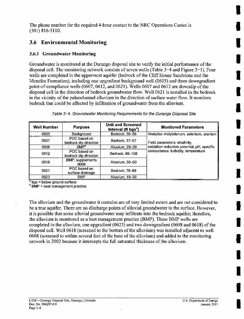
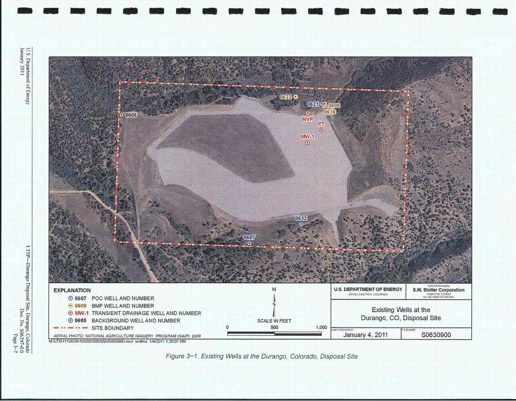
Groundwater is monitored at the Durango disposal site to verify the initial performance of thedisposal cell. The monitoring network consists of seven wells (Table 3-4 and Figure 3-1). FourWells are completed in the uppermost aquifer (bedrock of the Cliff House Sandstone and theMenefee Formation), including one upgradient background well (0605) and three downgradientpoint-of-compliance wells (0607, 0612, and 0621). Wells 0607 and 0612 are downdip of thedisposal cell in the direction of bedrock groundwater flow. Well 0621 is installed in the bedrockin the vicinity of the paleochannel alluvium in the direction of surface water flow. It monitorsbedrock that could be affected by infiltration of groundwater from the alluvium.
Table 3-4. Groundwater Monitoring Requirements for the Durango Disposal Site
Well Number Purpose Unit and Screened Monitored ParametersInterval (ft bgsa)0605 Background Bedrock; 36-56 Analytes: molybdenum, selenium, uranium
POC based on0607 bedrock dip direction Bedrock; 3757 Field parameters: alkalinity,0608 BMPD Alluvium; 29-39 oxidation-reduction potential, pH, specific
0612 POC based on Bedrock; 98-108 conductance, turbidity, temperature0612 ~bedrock dip direction Berc;9-0
0618 BMP; supplements Alluvium; 30-500608
POC based on0621 surface drainage Bedrock; 78-88
0623 BMP Alluvium; 19-39a bgs = below ground surfaceb BMP = best management practice
The alluvium and the groundwater it contains are of very limited extent and are not considered tobe a true aquifer. There are no discharge points of alluvial groundwater to the surface. However,it is possible that some alluvial groundwater may infiltrate into the bedrock aquifer; therefore,the alluvium is monitored as a best management practice (BMP). Three BMP wells arecompleted in the alluvium, one upgradient (0623) and two downgradient (0608 and 0618) of thedisposal cell. Well 0618 (screened to the bottom of the alluvium) was installed adjacent to well0608 (screened to within several feet of the base of the alluvium) and added to the monitoringnetwork in 2002 because it intercepts the full saturated thickness of the alluvium.
IIIUIIIIII3II3IIUIILTSP-Durango Disposal Site, Durango, Colorado
Doc. No. S06297-0.0Page 3-6
U.S. Department of EnergyJanuary 2011
m m G m
t-I
0..
0
rl
0O
EXPLANATION0 0607 POC WELLAND NUMBER® 0608 BMP WELLAND NUMBERo MW-1 TRANSIENT DRAINAGE WELL AND NUMBERE 0605 BACKGROUND WELLAND NUMBER
- . - - SITE BOUNDARY
U.S. DEPARTMENT OF ENERGY S.M. Stoller CorporationCAN MCIN ILRC NOK ~.ME COtI.N
Existing Wells at theDurango, CO, Disposal SiteSCALE IN FEET
5000 1,000
January 4, 2011 I S0630900AERIAL PHOTO: NATIONAL AGRICULTURE IMAGERY PROGRAM (NAIP), 2009mA
Figure 3-1. Existing Wells at the Durango, Colorado, Disposal Site
No wells at the Durango disposal site are explicitly designated as point-of-exposure (POE) wells.The POE would be considered to be any location outside of the site boundary where no
restrictions on groundwater use apply. The approved concentration limits for the site are basedon either MCLs or background and must be met at the POC wells. 3During the established groundwater monitoring period, routine monitoring is conducted toobserve possible changes in groundwater quality and to assess compliance with the groundwaterprotection standards. Indicator parameters were selected from the list of hazardous constituentsidentified for the site (Table 2-2 and Table 2-3). Indicator parameters are those that (1) areknown to be present in the tailings solutions at concentrations statistically greater thanbackground levels, (2) are present at much higher concentrations in the tailings solutions than inbackground, (3) display low variability in background, and (4) are mobile in the groundwaterenvironment. The parameters that best meet the first three criteria are arsenic, molybdenum, 3selenium, uranium, and vanadium. Of these, attenuation batch experiments indicate thatsubsurface sediments beneath the Durango disposal cell will adsorb all the vanadium and most ofthe arsenic in solution, some selenium and uranium, and a small amount of molybdenum 5(DOE 1991). Therefore, molybdenum, selenium, and uranium are the most reliable indicatorparameters of groundwater contamination at the Durango disposal site and were selected asrepresentative hazardous constituents for routine monitoring.
Routine monitoring consists of collecting groundwater samples annually at approximately thesame time each year to minimize variation due to seasonal effects. Samples are analyzed for the 3three indicator parameters. In addition, routine monitoring has included parameters that areindicative of general water quality. General water quality indicators monitored for are: pH,electrical conductivity, temperature, alkalinity, oxidation-reduction potential, turbidity i(Table 3-4). Monitoring requirements (both frequency and analytical parameters) will bereevaluated every 5 years. Changes to monitoring requirements may be recommended based onsite-specific conditions and will be concurred by NRC prior to implementation. 3The site-specific standards used for the three indicator parameters-molybdenum, selenium, anduranium-are the maximum observed background concentrations of these analytes reported in 3groundwater samples collected from wells completed in the bedrock aquifer as identified inTable 2-3. Exceedances of the site-specific standards are evaluated on a well-by-well basis. If alimit listed in Table 2-3 is exceeded at a POC well (0607, 0612, 0621), the well will be 5resampled within 1 year for all routine monitoring parameters (Table 2-2 and Table 3-4). If theresampling indicates a second exceedance of concentration limits for an indicator parameter, datawill be evaluated to determine if a cause for the exceedance can be identified. If a limit listed inTable 2-3 is exceeded at a BMP well (0608, 0618, 0623), no further action is required, howeverDOE may investigate the exceedance as a best management practice.
When resampling does not eliminate the disposal cell as the cause for a water-quality exceedancein a POC well, evaluative groundwater monitoring will be required. Evaluative groundwatermonitoring may include analysis of additional hazardous constituents, direct or indirectmeasurements of the disposal cell cover, or other activities that are determined to be appropriate.
The EPA standards (40 CFR 192.04 [c]) require implementation of a corrective action programwithin 18 months of verification of an established concentration limit exceedance for one ormore of the monitored constituents in a POC well. The goal of the corrective action program is torestore the disposal cell to its design specifications. If corrective action is determined necessary, 3LTSP-Durango Disposal Site, Durango, Colorado U.S. Department of EnergyDoc. No. S06297-0.0 January 2011 1Page 3-8
DOE will prepare and submit a corrective action plan for NRC review, and a copy of the planalso will be transmitted to CDPHE. The plan will include a monitoring plan to demonstrate theeffectiveness of the corrective action, which DOE will implement after consultation with NRCand CDPHE.
3.6.2 Vegetation Monitoring
A plant specialist or other qualified person will periodically participate in site inspections. If theinspection does not coincide with the general growing season, the plant specialist may conduct aseparate inspection at a more favorable time.
Volunteer plant growth: Volunteer plant growth includes plants growing where none wereplanned, such as in rock-lined drainage ditches, or unwanted plant species growing on thevegetated top slope of the disposal cell.
Based on results of a 1995 biointrusion study (DOE 1995), a volunteer plant root-to-shoot ratioof 1: 1 should be used unless site-specific plant data indicate otherwise. Based on a root-to-shootratio of 1:1, an unwanted plant species must be removed when its shoot height equals or exceeds3.5 ft (1.1 m) from the base of the plant. Unwanted plant species may be eliminated from thecover by selective spraying or mechanical removal.
3.7 Records
LM receives and maintains selected records to support post-closure site maintenance. Inactiverecords are preserved at a federal records center. Site records contain critical informationrequired to protect human health and the environment, manage land and assets, protect the legalinterests of DOE and the public, and mitigate community impacts resulting from the cleanup oflegacy waste.
The records are managed in accordance with the following requirements:
* Title 44 United States Code Chapter 29 (44 USC 29), "Records Management by theArchivist of the United States and by the Administrator of General Services"; 44 USC 31,"Records Management by Federal Agencies"; and 44 USC 33, "Disposal of Records."
* 36 CFR 1220 through 1238, Subchapter B, "Records Management."
* DOE Order 243.1, Records Management Program.
• Office of Legacy Management Information and Records Management Transition Guidance(DOE 2004).
3.8 Quality Assurance
The long-term care of the Durango disposal site and all activities related to the annual-surveillance, monitoring, and maintenance of the site comply with DOE Order 414.1 C, QualityAssurance, Applicable requirements of 10 CFR 830 Subpart A, "Quality AssuranceRequirements;", and ANSI/ASQ E4-2004, Quality Systems for Environmental Data andTechnology Programs: Requirements with Guidance for Use (American Society forQuality 2004).
U.S. Department of Energy LTSP-Durango Disposal Site, Durango, ColoradoJanuary 2011 Doc. No. S06297-0.0
Page 3-9
3.9 Health and Safety
Health and safety requirements and procedures for LM and Legacy Management Support (LMS)contractor activities are consistent with DOE orders, federal regulations, and applicable codesand standards. The DOE Integrated Safety Management System serves as the basis for the LMScontractor's health and safety program.
IIIIIi5Ii3IIIII£IUIU.S. Iiepartmerit or t~nergyLTSP-Durango Disposal Site, Durango, Colorado
Doc. No. S06297-0.0Page 3-10
U.J. Department ou anergyJanuary 2011
4.0 Beneficial Reuse Project
DOE has an initiative to increase the number of LM custody and control sites in beneficial reuseby fiscal year 2015. The Durango disposal site is one of the sites identified as a potential locationfor a beneficial reuse project.
4.1 Scope
DOE would consider two models for the type of beneficial reuse at the disposal site:
* DOE would make land available for lease to private industry or electric utilities. An exampleof this would be placement of solar photovoltaic panels on top of the disposal cell cover oron previously disturbed areas west of the cell for the generation of electricity.
* DOE would not lease access to the site but would coordinate with other govermnentagencies in management of site activities. An example of this would be coordinating siteactivities with state agencies to enhance site resources to the benefit of the local wildlifepopulation. Another example would be coordinating with government agencies in planninghiking trails that could use some of the Durango Disposal Site perimeter land.
Any potential reuse of the site will not be allowed without the concurrence of CDPHE and NRC.
4.2 National Environmental Policy Act
For any proposed reuse project, DOE will prepare National Environmental Policy Act (NEPA)documentation suitable to the scope of the proposed reuse project. Public involvement ornotification through meetings or electronic media is a required part of the NEPA process andwould be conducted in accordance with the level of community interest and scope of a proposedaction. An Environmental Assessment is an expected level of NEPA documentation that wouldbe associated with a renewable energy project, whereas a lower level of NEPA documentation(e.g., an Environmental Checklist leading to application of a Categorical Exclusion) may beappropriate for a small-scale project such as upgrading wildlife habitat with no impacts to thedisposal site.
4.3 Long-Term Lease Requirements
DOE will always maintain ownership of the disposal site and will not transfer or dispose of anyreal property interest without NRC concurrence. If DOE enters into a lease on the Durango site,all realty interest in the form of a lease shall be revocable, and the term of the lease shall belimited. Any lease shall require the lessee to restore the site to preexisting conditions at the endof reuse activities.
The minimum lease requirements and restrictions will include the following:
* Bonding and insurance;
* Duration and cost of lease;
* Site access, security, and fencing;
* Vendor requirements for utility coordination;
U.S. Department of Energy LTSP-Durango Disposal Site, Durango, ColoradoJanuary 2011 Doc. No. S06297-0.0
Page 4-I
* Permitting;
" Vendor water source and infrastructure requirements;
" Roles and responsibilities for compliance with environmental laws; 3" NRC and CDPHE approval and potential associated time requirements;
* Disposition and restoration; and 3* Additional restrictions and requirements that will ensure the proposal will not negatively
impact disposal cell maintenance and performance are described in Section 4.5, "MinimumTechnical Requirements." I
4.4 Potential Reuse Impacts
Despite any reuse, DOE will ultimately be responsible for ensuring the integrity of the Durangodisposal cell and for ensuring that it remains protective of human health and the environment. 5To ensure that any potential reuse does not have a negative impact on the cell, DOE wouldincrease the frequency of site inspections. The increased frequency of inspections will depend onthe type of reuse activity. IAppendix D presents a listing of potential reuse impacts related to a solar installation project onthe cell, based on requirements for the annual inspection, along with mitigation measures. Thistype of evaluation will be required for any reuse activity. Additional inspections related to reuseactivities will include a review of the initial anticipated impacts and verification that mitigationof those impacts remains effective as reuse activities progress.
4.5 Minimum Technical Requirements 3To ensure that reuse of the site does not interfere with the long-term care, the followingminimum technical requirements will be required for reuse activities. In the case of a reuseactivity with a lease to a private entity, these requirements will be imposed on the lessee throughthe lease.
4.5.1 Disposal Cell Cover
" Overall integrity of the disposal cell cover must remain intact;
" No grading can be done on the disposal cell cover;
" Rock armor on the channels and side slopes shall not be disturbed. An access road to the cellcover can be built across the northern diversion channel (Ditch No. 3) near its high point byusing geotextiles and free-draining aggregate to bridge over the riprap;
* Erosion protection: The project must not concentrate runoff to create a new runoff patternacross the cell cover. Runoff cannot cause erosion of the surface. Lessee must repair any 3surface erosion resulting from reuse;
* Infrastructure cannot anchor into the soils; electrical conduits must be placed aboveground; 3* Infrastructure cannot be within 5 ft of the site markers or monuments.
* Clear paths need to be maintained for all-terrain-vehicle access;
LTSP-Durango Disposal Site, Durango, Colorado U.S. Department of EnergyDoc. No. S06297-0.0 January 2011Page 4-2
* If utility trenching for high-voltage lines or small foundations is required, the depth ofexcavation is limited to a maximum of 24 inches, and shall not exceed the total area ofdisturbance specified in the lease. The top 6 inches of material (soil/rock matrix) must beseparated from deeper excavated soils. Soils must be placed back with 90 percent standardProctor compaction;
* Settlement: Loads shall not exceed 300 pounds per square foot bearing pressure onthe ground;
* Machinery used on the cover shall have rubber tires, be considered low ground pressureequipment, and not cause rutting. Nothing shall be allowed within 5 ft of the site marker(SMK-2) on the cover; and
* Existing grasses within the project footprint are to remain growing as much as practicable.Any grasses disturbed at the end of project shall be reseeded with approved seed mixture.
4.5.2 Entire Site
0 Lessee shall use their own lock on the entrance gate for continual access and "daisy chain"with DOE's lock. DOE shall have access to facility for spraying of noxious weeds,inspections, and maintenance of cell cover, as necessary. Lessee will determine if securityfencing is required. Improvements to the entrance gate and installing some new perimeterfence, as needed, should be considered as an alternative. The gate must be locked at alltimes.
Lessee can only access the site using designated routes and can only conduct operations andplace project structures in areas designated by DOE.
* DOE must have access to the solar facility for spraying noxious weeds, conductinginspections, and maintaining the cell cover.
" There is not water currently available on the site. No wells can be drilled within the propertyboundaries.
* Lessee is responsible for all improvements required for connections to the local grid orsubstations. As much of the infrastructure as possible shall be placed off of the cover.
* During the installation and reclamation of the panels and infrastructure, if traffic congestionoccurs temporary traffic control measures may be required.
* All maintenance areas, including sheds, shall be off of the cover in areas designated byDOE. Any hazardous materials required for construction or maintenance must be approvedby DOE before they are brought on site. Any hazardous material approved for use or storageshall have a Material Safety Data Sheet on site. Any spills shall be properly cleaned up andreported to DOE and any other required agencies. Fuel for equipment cannot be stored onsite. Vehicles and machinery can only be fueled off of the disposal cell.
* Delivery and staging of construction materials shall also occur off of the cover and sideslopes and in areas designated or approved by DOE.
* Cut slopes required as part of grading on areas off of disposal cell cover shall not be steeperthan 4H: IV. Natural drainage channels cannot be disturbed. All disturbed areas will berevegetated with approved seed mixture after installation and after infrastructure is removed.
* No activity would be allowed within 150 ft of the cultural site. Additionally, the lesseewould be responsible for informing all persons associated with the project that they would
U.S. Department of Energy LTSP-Durango Disposal Site, Durango, ColoradoJanuary 2011 Doc. No. S06297-0.0
Page 4-3
be subject to prosecution for knowingly disturbing cultural sites or collecting artifacts ofany kind.
* If fencing is required for site security, CDOW has requested that wildlife-exclusion fencingor wildlife-friendly fencing be installed.
" Overhead electrical lines may only be installed with advanced approval by DOE. If anoverhead electrical line is required, CDOW would require that a raptor-proof system beinstalled.
* After end of the lease, all equipment, fencing, electrical infrastructure, and other associatedimprovements shall be removed from the site. Except for approved grading changes, siteshall be restored to preexisting condition.
IIIIIIIIIUIIIIIII'IILTSP-Durango Disposal Site, Durango, Colorado
Doc. No. S06297-0.0Page 4-4
U.S. Department of EnergyJanuary 2011
5.0 References
10 CFR 40. U.S. Nuclear Regulatory Commission, "Domestic Licensing of Source Material,"Code of Federal Regulations, January 1, 2009.
10 CFR 830. U.S. Department of Energy, "Subpart A--Quality Assurance Requirements," Codeof Federal Regulations, January 1, 2009.
36 CFR 1220-1238. National Archives and Records, National Archives and RecordsAdministration, Subchapter B, "Records Management," Code of Federal Regulations,July 1, 2008.
40 CFR 192. U.S. Environmental Protection Agency, "Health and Environmental ProtectionStandards for Uranium and Thorium Mill Tailings," Code of Federal Regulations, July 1, 2009.
42 USC 7901 et seq. Uranium Mill Tailings Radiation Control Act, United States Code,November 8, 1978.
American Society for Quality, 2004. Quality Systems for Environmental Data and TechnologyPrograms: Requirements with Guidance for Use, ANSI/ASQ E4-2004.
DOE Order 231. 1A, Environment, Safety and Health Reporting, Change 1, June 3, 2004.
DOE Order 243.1, Records Management Program, February 3, 2006.
DOE Order 414.1C, Quality Assurance, June 17, 2005.
DOE Order 430.2B, Departmental Energy. Renewable Energy and Transportation Management,February 27, 2008.
DOE Order 450.1 A, Environmental Protection Program, June 4, 2008.
DOE Policy 450.2A, Identifying, Implementing, and Complying with Environment, Sqfety, andHealth Requirements, May 15, 1996.
DOE Policy 454.1, Use of Institutional Controls, April 9, 2003.
DOE (U.S. Department of Energy), 1991. Remedial Action Plan and Site Design forStabilization of the Inactive Uranium Mill Tailings Site at Durango, Colorado,UMTRA-DOE/AL-050503.0000, UMTRA Project Office, Albuquerque Operations Office,Albuquerque, New Mexico.
DOE (U.S. Department of Energy), 1993. 1992 Annual Prelicensing Inspection of the Durango,Colorado, UMTRA Project Disposal Site, DOE/ID/12584-141, UMTRA Project Office,Albuquerque Operations Office, Albuquerque, New Mexico.
U.S. Department of Energy LTSP-Durango Disposal Site, Durango, ColoradoJanuary 2011 Doc. No. S06297-0.0
Page 5-1
DOE (U.S. Department of Energy), 1995. UMTRA Project Disposal Cell Cover Biointrusion 3Sensitivity Assessment, DOE/AL/62350-200, Rev. 1, prepared for the U.S. Department 'fEnergy, Environmental Restoration Division, UMTRA Project Team, Albuquerque, NewMexico. 3DOE (U.S. Department of Energy), 1996. Long-Term Surveillance Plan for the Bodo CanyonDisposal Site, Durango, Colorado, DOE/AL/62350-77, Rev. 2, UMTRA Project Office, 3Albuquerque Operations Office, Albuquerque, New Mexico.
DOE (U.S. Department of Energy), 2001. Guidance for Implementing the Long-Term 3Surveillance Program for UMTRA Title I and Title II Disposal Sites, GJO-2001-215-TAR,UMTRA Project Office, Grand Junction Office, Grand Junction, Colorado.
DOE (U.S. Department of Energy), 2004. Office of Legacy Management Information andRecords Management Transition Guidance, Office of Legacy Management, March.
EPA (U.S. Environmental Protection Agency), 1992. Addendum to Interim Final GuidanceStatistical Analysis of Ground- Water Monitoring Data at RCRA Facilities, Office of Solid WasteManagement Division, U.S. Environmental Protection Agency, Washington, D.C.
EPA (U.S. Environmental Protection Agency), 2009. Statistical Analysis of GroundwaterMonitoring Data at RCRA Facilities, Unified Guidance, EPA 530-R-09-007, March.
Executive Order 13423. Strengthening Federal Environmental, Energy, and TransportationManagement, January 24, 2007.
Kirkham, R.M., and A.K. Navarre, 2003. Geologic Map of the Basin Mountain Quadrangle, La 3Plata County, Colorado, Colorado Geological Survey Open-File Report 0 1-4, 42 pp.,scale 1:24,000.
Kirkham, R.M., M.L. Gillam, T.D. Loseke, J.C. Ruf, and C.J. Carroll, 1999. Geologic Map of the a
Durango West Quadrangle, La Plata County, Colorado, Colorado Geological Survey Open-FileReport 99-4, 34 pp., scale 1:24,000. 3Lehmann, E.L., 1975. Nonparametrics-Statistical Methods Based on Ranks, prepared by theUniversity of California-Berkeley, with special assistance from H. J. M. D'Abrera of theUniversity of California-Berkeley, Holden-Day, Inc., San Francisco, California.
MK-F (Morrison Knudsen-Ferguson), 1991. Durango Draft Completion Report, prepared by iMorrison Knudsen-Ferguson for the U.S. Department of Energy, UMTRA Project Office,Albuquerque Operations Office, Albuquerque, New Mexico. I
LTSP-Durango Disposal Site, Durango, Colorado U.S. Department of EnergyDoc. No. S06297-0.0 January 2011Page 5-2
Appendix A
NRC Concurrence and Licensing Documentation

This page intentionally left blank
I
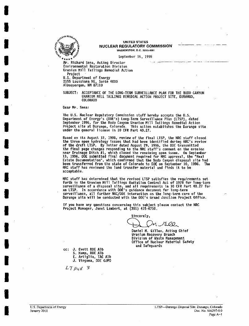
UNITED STATES
NUCLEAR REGULATORY COMMISSION'0 •• •WASHINGTON, D.C. 205o.-M1
September 16, 1996
Mr. Richard Sena, Acting DirectorEnvironmental Restoration DivisionUranium Mill Tailings Remedial Action
ProjectU.S. Department of Energy2155 Louisiana NE, Suite 4000Albuquerque, NM 87110
SUBJECT: ACCEPTANCE OF THE LONG-TERM SURVEILLANCE PLAN FOR THE BODO CANYONURANIUM MILL TAILINGS REMEDIAL ACTION PROJECT SITE, DURANGO,COLORADO
Dear Mr. Sena!
The U.S. Nuclear Regulatory Commission staff hereby accepts the U.S.Department of Energy's (DOE's) Long-Term Surveillance Plan (LTSP), datedSeptember 1996, for the Bodo Canyon Uranium Mill Tailings Remedial ActionProject site at Durango, Colorado. This action establishes the Durango siteunder the general license in 10 CFR Part 40.27.
Based on its August 12, 1996, review of the final LISP, the NRC staff closedthe three open hydrology issues that had been identified during NRC's reviewof the draft LTSP. By letter dated August 29, 1996, the DOE transmittedthe final page changes responding to the NRC staff's comment on the erosionnear Drainage Ditch #1, which closed the remaining open issue. On September13, 1996, DOE submitted final document required for NRC approval, the "RealEstate Documentation", which confirmed that the Bodo Canyon disposal site hadbeen transferred from the state of Colorado to DOE on September 10, 1996. TheNRC staff has reviewed the land transfer material and finds it to beacceptable.
NRC staff has determined that the revised LTSP satisfies the requirements setforth in the Uranium Mill Tailings Radiation Control Act of 1978 for long-termsurveillance of a disposal site, and all requirements in 10 CFR Part 40.27 foran LTSP. In accordance with DOE's guidance document for long-termsurveillance, all further NRC/DOE interaction on the long-term care of theDurango site will be conducted with the DOE's Grand Junction Project Office.
If you have any questions concerning this subject please contact the NRCProject Manager, Janet Lambert, at (301) 415-6710.
Sincerely,
Daniel M. Gillen, Acting ChiefUranium Recovery BranchDivision of Waste ManagementOffice of Nuclear Material Safety
and Safeguardscc: J. Evett DOE Alb
S. Hamp, DOE AlbE. Artiglia, TAC AlbJ. Virgona, DOE GJPO
/-2(d 3
U.S. Department of Energy LTSP-Durango Disposal Site, Durango, ColoradoJanuary 2011 Doc. No. S06297-0.0
Page A-I

IIUUNITED STATES
NUCLEAR REGULATORY COMMISSIONflJ "" • WASHINGTON. D.C. 20555-C0l
0' June 18, 1996
Mr. Richard Sena, Acting DirectorEnvironmental Restoration DivisionUranium Mill Tailings Remedial
Action ProjectU.S. Department of Energy2155 Louisiana NE, Suite 4000Albuquerque, NM 87110
SUBJECT: FINAL COMPLETION REVIEW REPORT FOR THE DURANGO, COLORADO,URANIUM MILL TAILINGS REMEDIAL ACTION PROJECT SITE
Dear Mr. Sena:
The U.S. Nuclear Regulatory Commission staff has completed its review of theU.S. Department of Energy's (DOE's) Final Completion Report for the UraniumMill Tailings Remedial Action Project inactive uranium mill tailings site atDurango, Colorado, submitted on October, 16, 1995. The review considerdpertintent documents associated with this site including revised CompletionReport pages transmitted by letters dated November 9, 1995, May 9, 1996, andMay 23, 1996. The NRC staff's review of the Completion Report is documentedin the final Durango Completion Review Report (Enclosure 1), which discussesthe staff's evaluation of the completed remedial action.
Based on its review of the Completion Report, NRC staff concurs that DOE hasperformed remedial action at the Durango site in accordance with the approvedplans and specifications, with the exception of the selection and performanceof a groundwater cleanup program. DOE, with NRC approval, has deferred thisaspect of the remedial action to a separate groundwater restoration program.The signed DOE Certification Summary providing official NRC concurrence incompletion of the Durango remedial action (other than groundwater cleanup), isenclosed.
-- 7 1
UUIIIIUIIUIIII
LTSP-Durango Disposal Site, Durango, ColoradoDoc. No. S06297-0.0Page A-2
U.S. Department of EnergyJanuary 2011 I
R. Sena -2 -
If you have any questions concerning this subject letter or the enclosures,-. pllease-contact-the-NRC-Project-Manager- for the Durango-site; -Janet Lambert, at
(301) 415-6710.
Sincerely,
Joseph J. Holonich, ChiefUranium Recovery BranchDivision of Waste ManagementOffice of Nuclear Material Safety
and Safeguards
Enclosures: As stated
cc: J. Evett, DOE AlbS. Hamp, DOE AlbE. Artiglia, TAC Alb
U.S. Department of EnergyJanuary 2011
LTSP-Durango Disposal Site, Durango, ColoradoDoe. No. S06297-0.0
Page A-3
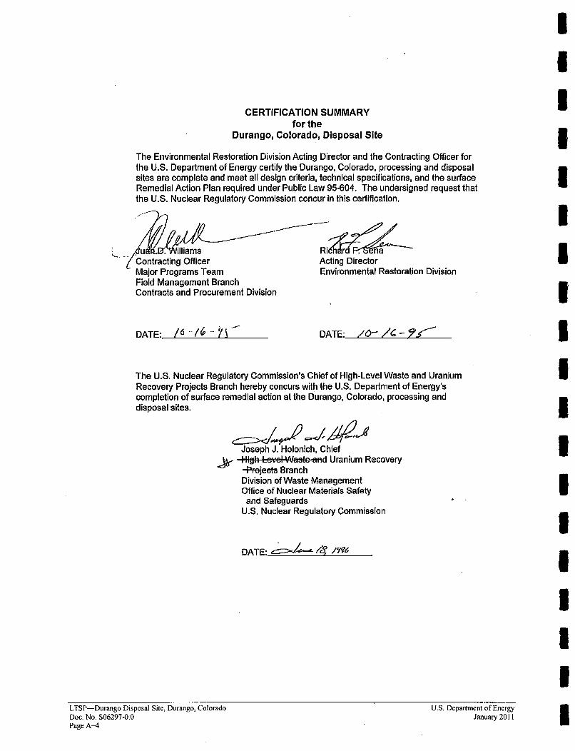
CERTIFICATION SUMMARYfor the
Durango, Colorado, Disposal Site
The Environmental Restoration Division Acting Director and the Contracting Officer forthe U.S. Department of Energy certify the Durango, Colorado, processing and disposalsites are complete and meet all design criteria, technical specifications, and the surfaceRemedial Action Plan required under Public Law 95-604. The undersigned request thatthe U.S. Nuclear Regulatory Commission concur in this certification.
& ... /U 'W•illiams' Contracting Officer
Major Programs TeamField Management BranchContracts and Procurement Division
DATE: _6_-16____
Acting DirectorEnvironmental Restoration Division
DATE: /0- "/6-_1: '
IIIIUIIIIIIIIUIIUII
The U.S. Nuclear Regulatory Commission's Chief of High-Level Waste and UraniumRecovery Projects Branch hereby concurs with the U.S. Department of Energy'scompletion of surface remedial action at the Durango, Colorado, processing anddisposal sites.
Joseph J. Holonich, ChiefHigh Lzvd Waste and Uranium Recovery-Pfejects BranchDivision of Waste ManagementOffice of Nuclear Materials Safety
and SafeguardsU.S. Nuclear Regulatory Commission
DATE: /8- 1w-/ l5'
LTSP-Durango Disposal Site, Durango, ColoradoDoc. No. S06297-0.0Page A-4
U.S. Department of EnergyJanuary 2011
Appendix B
Site Ownership/Custody Documentation
IThis page intentionally left blank I
II
RIEAL ESTATE DOCUMEN'I'ATIONLONG-TEIRM SURVEILLANCE PLAN
DURANGO, CO, DISPOSAL SITEDURANGO, COLORADO
GENERAL
Pursuant to Section 106 of the Uranium Mill Tailings Radiation Control Act, 42 U.S.C.§7901 et seq., Public Law 95-604, the Colorado Department of Public Health andEnvironment acquired two parcels of property that would become the Durango DisposalSite. The first tract, Tract 101 was acquired from the Colorado Department of NaturalResources, Division of Wildlife, through a quitclaim deed dated August 4, 1987. Thistract consisted of 38.7 acres (1.5.7 ha). The second tract, Tract 102, was acquired froiu theState L.and Board and consisted of 81.36 acres (32.93 ha).
A portion of the land for the site was conveyed in 1975 to the State of Colorado, Divisionof Wildlife from the Nature Conservancy with the agreement the land would be used forthe express purpose of a wildlife habitat, would have uses consistent with sound gamemanagement, and would have no commercial uses, The 1975 conveyance stated thatshould a breach of the agreement occur, the affected land may revert to the NatureConservancy. The Nature Conservancy quitelaimed all rights to the property in August1994 to the State of Colorado.
The State of Colorado could thereby quitclaim both Tracts to the United States ofAmerica with clear title in August 1996. The quitclahn deeds were duly recorded in LaPlata County, Colorado in December 1996.
LEGAL DESCRIPTIONS
The legal descriptions are provided on the attached quitelain deeds.
REPOSITORY
Real estate correspondence and related documents are maintained in the real propertyportion of project records and worlding copies can be easily accessed by contactingDOE's Office of Legacy. Management realty staff or contractor realty staff.
U.S. Department of EnergyJanuary 2011
LTSP-Durango Disposal Site, Durango, ColoradoDoc. No. S06297-0.0
Page B-I
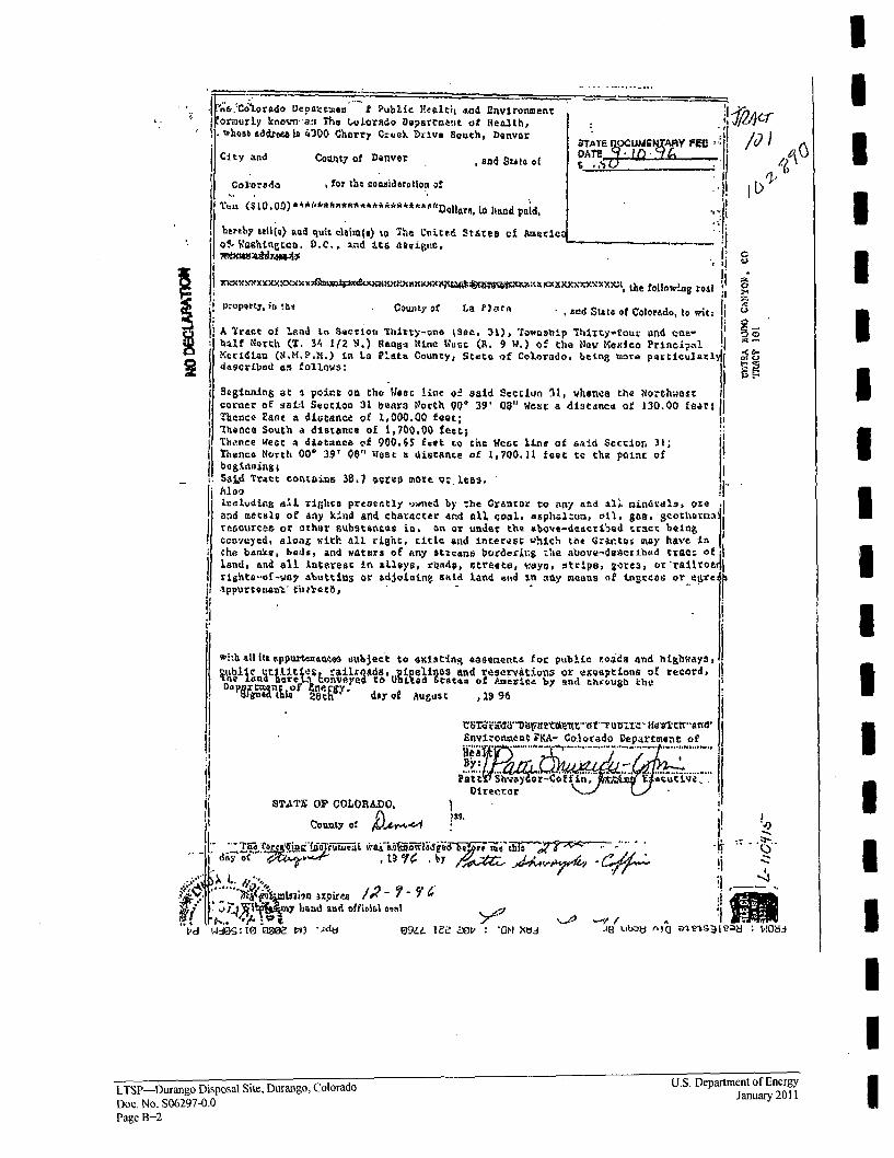
I
I
*1!'`&,Co'i1orsdo Deawctxon f public V41t0t -%ad flmvironanf.Ourykor-a The twJoRdo Department of Hea~lth,whotte aiddtee la 4300 Cherry Creek. Drium South, r baver
City and Cov~ty of Denver ,and stlat o4 S* __ _ _ "TF
loaa for the consideration a!~
Tuu lam La00 liAIa~*.i*~ ~&*.f~oos ~hnd paid.berab7 sell'(0) Qud quit elaian(a) %o The L'it4Stares of Americ
'of, Washtngcou. D.C. , and :La tsaooigpc.
I K 9C w~1ruu~aX1 x~X~lthe fofllawlag rest
p-oport, io !tCounty of La ?3.ata acsd SttEo of Color~ado, to wit;: (
A Tract of land ics Sacclott Thirty-=on t~et, 31), irawebip, Thlity-four amnd one-hal~f tNotrl (T. 34i 1(2 i.) 1RaciliA Nine Wartt (R. 9 W.) o! the Noav Mexico PrIncijmalMertidian in..P). La Pl~ata, County, Stato of Colorado, being toore qtclrdegCrLbad an follows:~tl
I BagimmiLn& at -a Voiont on thu'ea line hol s aid Sectlun 31, whjentie the tNorthwmec 11corner of gail. Sectioo 31 bears tVortl% 00 39' 03" Weat a distance of 130.00 fear IJThence Eant a distance~ of 1,000.00 feet;'Thence South a distance of 1,700.90O feet;
ITha.nte West gi diatanca vi 900.65 ftot to turn West line of asld Section. 31;Thence Ncortli 000 39? 00" VWest a distance of 1,700.11 feet tc the point: of
SATrc ootaills 38, L 7vera mote, 9-. les.
resources or other suhstsAncs in, on or under the above-descriOed tract being Jccoveyedo a.1oa& with' all, right;, title and immteres; uhichm the Grar.tor smay have In I
I
che bArLes bads, and waters of any Strcans bordering the above-dlescribed tzac:ofland, and all Interest in alloys, r~advp Strete, v.ayo. strips, &gores, utt'rilto;41rights-of-vay allouttinS or adjoining said land and in jny means of teigreas or,.eare4b.1ppuirso:Lan'L th?'zrt;3, - 11i
IIU
IIIUIIU3IIIII
With all it& dpuroac~ ubject to existing easemsents for public roids 4nd highiwayS,
'1 It, rairods gule an reevt ons OXexptions of rec~rd,De'NCK' day 9A August ID1 96
Envl-onotent iý!A- Colorado Departeont of.91fcW
By~/-~~,. C t
STATE OP COLOfTL4DO,
County of kr,-
I'd
.~~ Lsuion ;xpirea Yato~yhnS -And offitifil ovasl
t4_ioq,: to go pl 0i9U. TEE Zop 0N1 2 Wj.
law~
al~ leaI V08
II
LTSP--Durango Disposal Site, Durango, Colorado U.S. Department of Energy
Doe. No. S06297-0.0 January 2011
Page B-2
IIIIIIIIIUIIIIIUIII
'lowNo. 6M& wry7 C"K O2W.-sk..d I%?*-~
•'.•,z^ ~ ~ ~ ~ -- al' IN•ol~C. 1119 %/On S.W. :Wel.•~ y • f ,• ¢)/ " ,/r W7w. 4 . ,01-1.5
~Cd WIdG:TG 00ti") %idk) 09t.1 TZ Z1 : 'ON XUJ ,18 ub~~u Ala ajeSj~ea8: 1~-18
U.S. Department of EnergyJanuary 2011
LTSP-Durango Disposal Site, Durango, ColoradoDoc. No. S06297-0.0
Page B-3
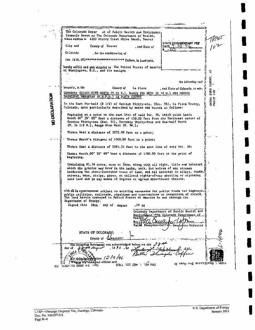
T Colorado Depar""At Qof Public Hiealthi and Envivlortmeiformerly lkiovn as The Colorado Department o~ eshIw hoss address M 42300 Cherry C.-kok Drive Sbuth. Denver
City and Ce5unty of D'ette . and Stmle o!IJCclo-ado t or theoo 0i~du-iktlqr of
Ten ( .OA&*A~seA*AaeDollars, in hand paid,
DAT-Z t~q FEe _
Iib~erth sell(a) and qutaL kma to The United State% ef Americ~of Washjgtot, D.C., add its aseigno
the follawinr real
proipcrcy, !ai the County of LA Pl.ata *and SW,* 91 Goloredo. 'o witi
TOMMY8Ht THItT-FIVE14Oll (T.35 B~.), RM±CE M WEST (It 10 W.) N%2 MIJFR~cpl.MR1DB RXFKY LARAA COUTY
In the zSat One-half (z 1/2)k of scc~io ITlrity-six, (Sec:. 36), La Plata-Ccuncy,
Cgo3tado, wr particnuasrLy dgstvibed by mocee and bounda as follows:
8980uning at a point on the Quat line of said 3sc. 36, which point bearsBoutti 00' 391 08"1 Bast a dixtance of 13D.00 feet from the Northw~est cornez of
Sectiton Thiyty-ono (Sec. 31), Tovnahip Thi~rt-fauir and One-half NorthMT 34 l/Z M.), Kanga NlnA Wert (R. 94.);
Thence Wtest'a ditantae of 2075.00 foot to a oit
-Thence' ftuuhra diszAnce of 1700.00 f et to a point:
Thence Ea~st a distanct of 2094.35 foot to the east l.ine of said Sdc. 361
Thence. tNrth.000 391 0$" Ileat a distance -A 110C.00 feet to the point of
Conttaining 51.36 acres. 2i~re or lisa, along with all righir, title and intexeutwhich the grbrmror woay havj* in the banks, bed's, Wnd 'wsors of any atreaai5borderi~ng the above-deacribad tract of land, and aLl interest in alleys. roads,
streetq, vays, strip3, gorss, or railroad rjghto-of-g:ay atjuteLag or adjoflnina
eaad land and la any Meanne of iritess or egress appureenuan thcreto.
WthAfliAPPnxTIa"AA a oubjgoc to axistirm8 easemeuta for puibLic roads noud highw;yu,
Vublic utilitiec. railroads, pipalinsoe nd 'reservations or avxcejtion4 of rcord.
The land hortdia conveyed to Uoiced State% of America by and through theDeparttednet or Energy.
Sitned thi* 28th da4y of AUgurt .19 96
0
IIIIIIIUIUIIII
I.
Colorado Dlepartment ;if Public Health end
En FZTAColorado D~j T~1QL
.6 ...............
STATE OF OOLO 0•. I
-T~~~T ooreaieng wnt4Ln waa acknowledged baefr.ne =9tisi 2?
II at ;'• • •o."•••" .a" "t• oiiY o ~&1fd Arv a 19ica b
Z? WdGý: To 00&-t,. --- l 09AL IMZ z~ 'ON XV ~ *gu~ I3~~li 10j
LTSP>-Durango Disposal Site, Durango, Colorado U.S. Departmentuof Energy
Doc. No. S06297-0.0Page B-4
III
Appendix C
Inspection Checklist and Photo Log
This page intentionally left blank

2009 INSPECTION CHECKLISTDURANGO, COLORADO, DISPOSAL SITE
Status of Site InspectionsDate of This Revision:
Last Annual Inspection:Inspectors:
May 27, 2009
May 28, 2008M. Kastens (lead) and L Sheader
May 28, 2009M. Kastens (lead) and L. Sheader
Next Annual Inspection (Planned):Scheduled Inspectors:
No. ITEM ISSUE ACTIONI Access There are no access protocols.2 Participants Contact Wendy Naugle of CDPHE at (303) Wendy Naugle of CDPHE will meet the inspectors at the
692-3394. site at 1:00 p.m. on 5/28/09.
We will have copies of the 2008 trip report and extrainspection maps available.
Conduct tailgate safety meeting. Tripping, ticks andrattlesnakes hazards will be discussed.
3 Specific Site See attached list. Inspect.Surveillance Features
4 Vandalism Vandalism is an ongoing problem at this site. Record evidence of vandalism at the site.
The entrance sign and several perimeter signs Check entrance, P 1, and P82 signs; replace damaged signsare repeatedly stolen or damaged by bullets and if necessary.shotgun shot. Several perimeter signs havebeen reinforced with steel frames. Determine ifthe entrance sign and perimeter signs PI andP82 were replaced in 2008. Perimeter sign P2 ismissing and will not be replaced.
Entrance site marker SMK-I has been Check legibility of SMK-I.damaged in the past.
Trash is sometimes illegally dumped near the Check for illegal dumping.site entrance.
5 Top slope The top of the cell was in excellent condition in Check for evidence of settling, slumping, or erosion.2008.
The top slope was seeded with grasses. Evaluate condition of the vegetation and record noxiousVegetation was healthy in 2008 (yellow sweet weed locations. Check top slope for sagebrush and otherclover was a minor component, unlike previous deep-rooted shrubs and trees; these will be treated withyears). Small infestations of musk thistle, a herbicide by a subcontractor. (LTSP states that annoxious weed, were found in several areas on unwanted plant species must be removed when its shootthe cell cover in previous years; these were height equals or exceeds 3.5 ft from the base of the plant.)treated with herbicide. No deep-rooted woodyspecies greater than 3 ft in height were found in2008.
Dryland alfalfa, a deep-rooted forb species, has Check cell top for alfalfa plants. Mark with orangebeen found on the cell and treated with flagging if found.herbicide. Inspectors questioned whether thisplant species should be controlled, as itsaboveground height will never exceed the 3.5-foot criterion listed in the LTSP. DOEdetermined that it should be controlled. Since2006, alfalfa plants on the cell top have beentreated with herbicide
Small mammal burrows have been observed Continue to check for burrowing and evaluate if it affectsnear site marker SMK-2. the integrity of the cell cover.
U.S. Department of EnergyJanuary 2011
LTSP-Durango Disposal Site, Durango, ColoradoDoc. No. S06297-0.0
Page C-I
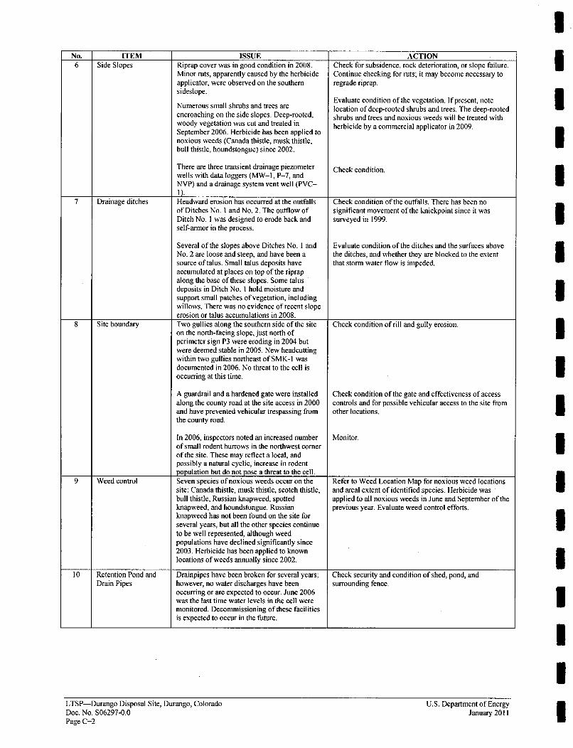
No. ITEM ISSUE ACTION6 Side Slopes Riprap cover was in good condition in 2008. Check for subsidence, rock deterioration, or slope failure.
Minor ruts, apparently caused by the herbicide Continue checking for ruts; it may become necessary toapplicator, were observed on the southern regrade riprap.sideslope.
Evaluate condition of the vegetation. If present, noteNumerous small shrubs and trees are location of deep-rooted shrubs and trees. The deep-rootedencroaching on the side slopes. Deep-rooted, shrubs and trees and noxious weeds will be treated withwoody vegetation was cut and treated in herbicide by a commercial applicator in 2009.September 2006. Herbicide has been applied tonoxious weeds (Canada thistle, musk thistle,bull thistle, houndstongue) since 2002.
There are three transient drainage piezometer Check condition.wells with data loggers (MW-I, P-7, andNVP) and a drainage system vent well (PVC-I).
7 Drainage ditches Headward erosion has occurred at the outfalls Check condition of the outfalls. There has been noof Ditches No. I and No. 2. The outflow of significant movement of the knickpoint since it wasDitch No. I was designed to erode back and surveyed in 1999.self-armor in the process.
Several of the slopes above Ditches No. I and Evaluate condition of the ditches and the surfaces aboveNo. 2 are loose and steep, and have been a the ditches, and whether they are blocked to the extentsource of talus. Small talus deposits have that storm water flow is impeded.accumulated at places on top of the riprapalong the base of these slopes. Some talusdeposits in Ditch No. I hold moisture andsupport small patches of vegetation, includingwillows. There was no evidence of recent slopeerosion or talus accumulations in 2008.
8 Site boundary Two gullies along the southern side of the site Check condition of rill and gully erosion.on the north-facing slope, just north ofperimeter sign P3 were eroding in 2004 butwere deemed stable in 2005. New headcuttingwithin two gullies northeast of SMK-1 wasdocumented in 2006. No threat to the cell isoccurring at this time.
A guardrail and a hardened gate were installed Check condition of the gate and effectiveness of accessalong the county road at the site access in 2000 controls and for possible vehicular access to the site fromand have prevented vehicular trespassing from other locations.the county road.
In 2006, inspectors noted an increased number Monitor.of small rodent burrows in the northwest comerof the site. These may reflect a local, andpossibly a natural cyclic, increase in rodentpopulation but do not pose a threat to the cell.
9 Weed control Seven species of noxious weeds occur on the Refer to Weed Location Map for noxious weed locationssite: Canada thistle, musk thistle, scotch thistle, and areal extent of identified species. Herbicide wasbull thistle, Russian knapweed, spotted applied to all noxious weeds in June and September of theknapweed, and houndstongue. Russian previous year. Evaluate weed control efforts.knapweed has not been found on the site forseveral years, but all the other species continueto be well represented, although weedpopulations have declined significantly since2003. Herbicide has been applied to knownlocations of weeds annually since 2002.
10 Retention Pond and Drainpipes have been broken for several years; Check security and condition of shed, pond, andDrain Pipes however, no water discharges have been surrounding fence.
occurring or are expected to occur. June 2006was the last time water levels in the cell weremonitored. Decommissioning of these facilitiesis expected to occur in the future.
IIIIIIIIIII1IIIII1ILTSP-Durango Disposal Site, Durango, Colorado
Doc. No. S06297-0.0Page C-2
U.S. Department of EnergyJanuary 2011

No. ITEM. ISSUE ACTIONII Outlying area The Animas/La Plata Reservoir is under Check for activities that could affect site security and
construction, and a new utility corridor was integrity. If possible, remove the oak brush obscuring thebuilt near the west side of the site. Boundary view of the BM-6 witness corner.monument BM-6 was destroyed when apipeline was laid during construction. It wasdecided not to replace it, as the nearby witnesscomers are still in place. In 2006, inspectorsnoted that the northern witness comer wasbecoming overgrown with oak brush.
Specific Site Surveillance Features-Durango, Colorado, Disposal Site
FEA TURE COMMENT
Entrance Sign (1) Could be defaced or missing.
Perimeter Signs (81) Several could be defaced or missing. P2 is missing and will not be replaced. P44 isbeing undercut by erosion-monitor.
Site Markers (2) SMK-l (near the entrance gate) is pockmarked from bullets.
Survey Monuments (4)
Boundary Monuments (6) BM-3 and two of its associated reference markers are exposed to erosion. BM-6 ismissing due to pipeline construction; it was not replaced because two witnessmonuments near this property comer are intact and will be used to identify the SWcomer of the site. Cut oakbrush away from northem BM-6 witness comer.
Monitor Wells (7) MW-0605 (upgradient background)MW-0607 (downgradient POC)MW-0608 (downgradient alluvium)MW-0612 (downgradient POC)
MW-0618 (companion well to MW-0608 added to network because screenplacement is more appropriate than designated well)MW-0621 (downgradient POC)MW-0623 (upgradient alluvium)
Settlement Plates (14) Do not need to be checked.Retention Pond Check condition of retention pond and surrounding fence. Check for leaks in the
shed (beware of rodent infestation).
U.S. Department of EnergyJanuary 2011
LTSP-Durango Disposal Site, Durango, ColoradoDoc. No. S06297-0.0
Page C-3
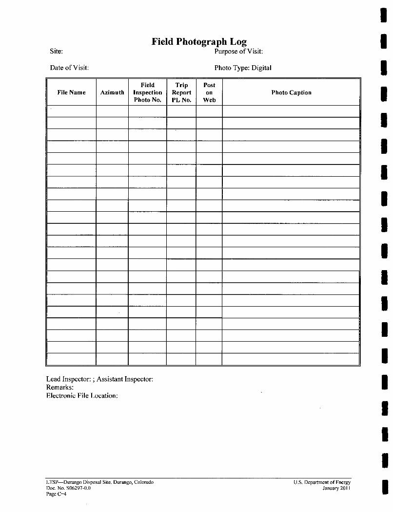
Site:
Date of Visit:
Field Photograph LogPurpose of Visit:
Photo Type: Digital
Field Trip PostFile Name Azimuth Inspection Report on Photo Caption
Photo No. PL No. Web
I- t I
-t .t I t I
-t 4 I *
+ + 4 I I
I t I
Lead Inspector: ; Assistant Inspector:Remarks:Electronic File Location:
LTSP-Durango Disposal Site, Durango, ColoradoDoc. No. S06297-0.0Page C-4
U.S. Department of EnergyJanuary 2011
Appendix D
Reuse Potential Impacts Matrix
U
IThis page intentionally left blank i
IUIIIIIII
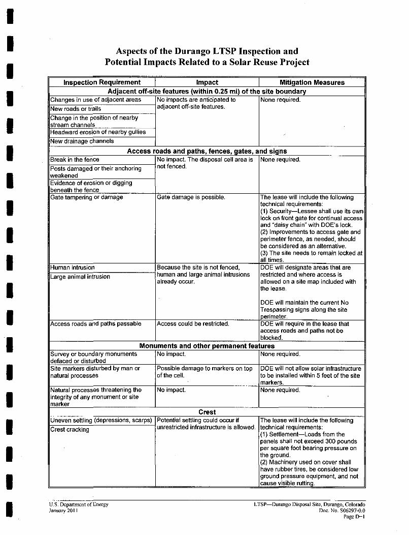
Aspects of the Durango LTSP Inspection andPotential Impacts Related to a Solar Reuse Project
Inspection Requirement Impact Mitigation MeasuresAdjacent off-site features (within 0.25 mi) of the site boundary
Changes in use of adjacent areas No impacts are anticipated to None required.New roads or trails adjacent off-site features.
Change in the position of nearbystream channelsHeadward erosion of nearby gulliesNew drainage channels
Access roads and paths, fences, gates, and signs
Break in the fence No impact. The disposal cell area is None required.Posts damaged or their anchoring not fenced.weakenedEvidence of erosion or diggingbeneath the fenceGate tampering or damage Gate damage is possible. The lease will include the following
technical requirements:(1) Security-Lessee shall use its ownlock on front gate for continual accessand "daisy chain" with DOE's lock.(2) Improvements to access gate andperimeter fence, as needed, shouldbe considered as an alternative.(3) The site needs to remain locked atall times.
Human intrusion Because the site is not fenced, DOE will designate areas that areLarge animal intrusion human and large animal intrusions restricted and where access is
already occur. allowed on a site map included withthe lease.
DOE will maintain the current NoTrespassing signs along the siteperimeter.
Access roads and paths passable Access could be restricted. DOE will require in the lease thataccess roads and paths not beblocked.
Monuments and other permanent featuresSurvey or boundary monuments No impact. None required.defaced or disturbedSite markers disturbed by man or Possible damage to markers on top DOE will not allow solar infrastructurenatural processes of the cell. to be installed within 5 feet of the site
markers.Natural processes threatening the No impact. None required.integrity of any monument or sitemarker
CrestUneven settling (depressions, scarps) Potential settling could occur if The lease will include the followingCrest cracking unrestricted infrastructure is allowed, technical requirements:
(1) Settlement-Loads from thepanels shall not exceed 300 poundsper square foot bearing pressure onthe ground.(2) Machinery used on cover shallhave rubber tires, be considered lowground pressure equipment, and notcause visible rutting.
U.S. Department of EnergyJanuary 2011
LTSP-Durango Disposal Site, Durango, ColoradoDoc. No. S06297-0.0
Page D- I

Inspection Requirement Impact Mitigation MeasuresOuter cover layer breached It is anticipated that some trenching The lease will include the following
and shallow foundations in the frost technical requirements:barrier of the cover layer may occur. (1) Utility trenching or small
foundations are limited to a maximumdepth of excavation into the cover of24 inches. The top 6 inches ofmaterial (soil/rock matrix) must beseparated from deeper excavatedsoils. Soils must be placed back with90% standard Proctor compaction.(2) No grading can be performed onthe disposal cell cover.(3) Overall integrity of the disposal cellcover must remain intact
Evidence of erosion Solar infrastructure could create a The lease will include the following(1) By water situation in which water running off technical requirement:(2) By wind panels might lead to minor erosion. (1) Erosion Protection-Panels must
There would be no increase in the not concentrate runoff to create a newpotential for wind erosion. runoff pattern a cross the cell cover.
Water running off panels cannotcause erosion of the surface. Lesseemust repair any erosion that occurs onthe surface.
Additionally, DOE will increase thefrequency of site inspections toensure that potential erosion or anyother negative impacts are identifiedand remedied before they become
_____________________________significant.Evidence of animal burrowing No impact. None required.
SlopesEvidence of gradual down slope Down slope movement and/or The lease will include the followingmovement or creep (terraces, cracking could potentially occur if the technical requirement:deflection of plants) rock armor of the side slopes is not (1) Rock armor on the channels andSlope cracking protected. side slopes shall not be disturbed.Depressions or bulges on the slope Depressions or bulges could occur The lease restrictions requiring the
on the slopes with excessive loading rock armor not be disturbed (above),or changes to the rock armor. and the minimal load allowances on
top of the cell will be protective of theside slopes of the cell.
Outer cover layer breach No impact. The proposed lease language will notallow any breach of the cover layer onthe slopes.
Evidence of erosion: There will be no erosion impact due The lease will include language that(1) By water to wind. Erosion or channeling due to would require that any site(2) By Wind increased or preferential water flow infrastructure include a method for
_______________________could occur. moving excess water away from theChannelized water runoff (rivulets, slopes to prevent erosion orgullies) channeling.
DOE will increase the frequency ofsite inspections to ensure thatpotential erosion, or any othernegative impacts are identified andremedied before they becomesignifcant.
Evidence of seepage (moisture, color, No impact. None required.vegetation)Evidence of animal burrowing No impact. None required.
IIIIIIIIIII1I1III1ILTSP-Durango Disposal Site, Durango, Colorado
Doc. No. S06297-0.0Page D-2
U.S. Department of EnergyJanuary 2011
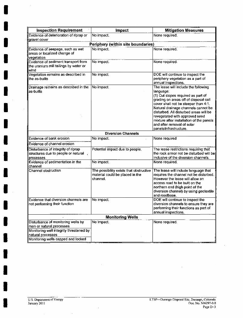
Inspection Requirement Impact Mitigation MeasuresEvidence of deterioration of riprap or No impact. None required.gravel cover
Periphery (within site boundaries)Evidence of seepage, such as wet No impact. None required.areas or localized change ofvegetationEvidence of sediment transport from No impact. None required.the uranium mill tailings by water orwindVegetation remains as described in No impact. DOE will continue to inspect thethe as-builts periphery vegetation as a part of
annual inspections.Drainage remains as described in the No impact. The lease will include the followingas-builts language:
(1) Cut slopes required as part ofgrading on areas off of disposal cellcover shall not be steeper than 4:1.Natural drainage channels cannot bedisturbed. All disturbed areas will berevegetated with approved seedmixture after installation of the panelsand after removal of solarpanels/infrastructure.
Diversion ChannelsEvidence of bank erosion No impact. None requiredEvidence of channel erosionDisturbance of integrity of riprap Potential impact due to people. The lease restrictions requiring thatstructures due to people or natural o the rock armor not be disturbed will beprocesses inclusive of the diversion channels.Evidence of sedimentation in the No impact. None required.channelChannel obstruction The possibility exists that obstructive The lease will include language that
material could be placed in the requires the channel not be disturbed.channel. However the lease will allow an
access road to be built on thenorthern end (high point of thediversion channel) by using geotextileand roadbase.
Evidence that diversion channels are No impact. DOE will continue to inspect thenot performing their function diversion channels to ensure they are
performing their functions as part ofannual inspections.
Monitoring WellsDisturbance of monitoring wells by No impact. None required.man or natural processesMonitoring well integrity threatened bynatural processesMonitoring wells capped and locked
U.S. Department of EnergyJanuary 2011
LTSP-Durango Disposal Site, Durango, ColoradoDoc. No. S06297-0.0
Page D-3
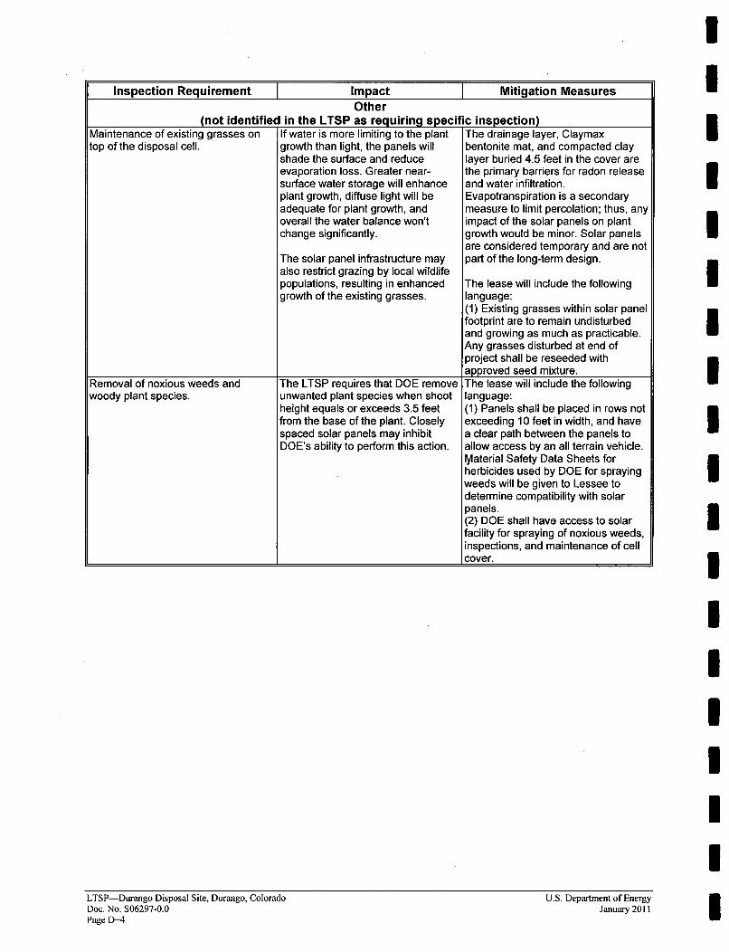
Inspection Requirement Impact Mitigation MeasuresOther
(not identified in the LTSP as requiring specific inspection)Maintenance of existing grasses on If water is more limiting to the plant The drainage layer, Claymaxtop of the disposal cell. growth than light, the panels will bentonite mat, and compacted clay
shade the surface and reduce layer buried 4.5 feet in the cover areevaporation loss. Greater near- the primary barriers for radon releasesurface water storage will enhance and water infiltration.plant growth, diffuse light will be Evapotranspiration is a secondaryadequate for plant growth, and measure to limit percolation; thus, anyoverall the water balance won't impact of the solar panels on plantchange significantly. growth would be minor. Solar panels
are considered temporary and are notThe solar panel infrastructure may part of the long-term design.also restrict grazing by local wildlifepopulations, resulting in enhanced The lease will include the followinggrowth of the existing grasses. language:
(1) Existing grasses within solar panelfootprint are to remain undisturbedand growing as much as practicable.Any grasses disturbed at end ofproject shall be reseeded withapproved seed mixture.
Removal of noxious weeds and The LTSP requires that DOE remove The lease will include the followingwoody plant species. unwanted plant species when shoot language:
height equals or exceeds 3.5 feet (1) Panels shall be placed in rows notfrom the base of the plant. Closely exceeding 10 feet in width, and havespaced solar panels may inhibit a clear path between the panels toDOE's ability to perform this action. allow access by an all terrain vehicle.
Material Safety Data Sheets forherbicides used by DOE for sprayingweeds will be given to Lessee todetermine compatibility with solarpanels.(2) DOE shall have access to solarfacility for spraying of noxious weeds,inspections, and maintenance of cellcover.
IIIIIIIIIII
I
LTSP-Durango Disposal Site, Durango, ColoradoDoc. No. S06297-0.0Page D-4
U.S. Department of EnergyJanuary 2011