Embed Size (px)
Citation preview

Long-Range Battery Electric Vehicle with Megawatt Wireless Charging
Principal Investigator:
Brian LindgrenKenworth Truck Company
Project ID: elt262
DOE Vehicle Technologies Program
2021 Annual Merit Review
This presentation does not contain any proprietary, confidential, or otherwise restricted information
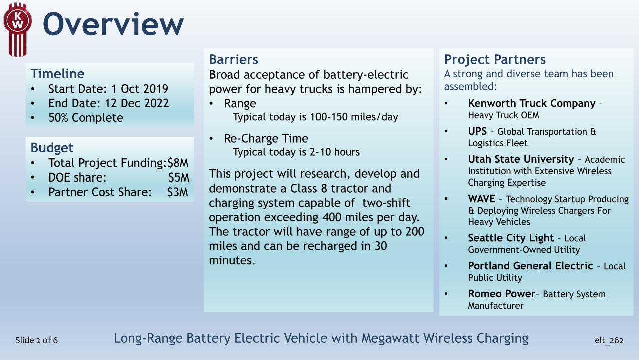
Overview
Slide 2 of 6
Timeline• Start Date: 1 Oct 2019
• End Date: 12 Dec 2022
• 50% Complete
Budget• Total Project Funding:$8M
• DOE share: $5M
• Partner Cost Share: $3M
BarriersBroad acceptance of battery-electric
power for heavy trucks is hampered by:
• RangeTypical today is 100-150 miles/day
• Re-Charge TimeTypical today is 2-10 hours
This project will research, develop and
demonstrate a Class 8 tractor and
charging system capable of two-shift
operation exceeding 400 miles per day.
The tractor will have range of up to 200
miles and can be recharged in 30
minutes.
Project PartnersA strong and diverse team has been
assembled:
• Kenworth Truck Company –Heavy Truck OEM
• UPS – Global Transportation &
Logistics Fleet
• Utah State University – Academic
Institution with Extensive Wireless
Charging Expertise
• WAVE – Technology Startup Producing
& Deploying Wireless Chargers For
Heavy Vehicles
• Seattle City Light – Local
Government-Owned Utility
• Portland General Electric – Local
Public Utility
• Romeo Power– Battery System
Manufacturer
Long-Range Battery Electric Vehicle with Megawatt Wireless Charging elt_262

Relevance
Slide 3 of n
ImpactHeavy-Duty BEVs are struggling to gain
acceptance by trucking fleets.
• Increasing the range of heavy trucks will
allow fleets to more easily integrate BEVs
into daily routes
• Reducing the charge time will allow fleets
to operate BEVs in two-shift operations
• Minimizing battery size while maximizing
daily range will allow a smaller increase
in initial purchase price and a smaller
reduction in payload capability compared
with today’s diesel powertrains
• Wireless power transfer will allow safe
and efficient extreme fast charging with
minimal driver interaction (no large,
heavy cable to wrestle)
Long-Range Battery Electric Vehicle with Megawatt Wireless Charging elt_262
Objectives• Reduced energy use throughout the BEV
system to improve kW-h/mile
• Baseline test vehicles were measured
at an average of 2.65 kW-h/mile
• System efficiencies in traction
motor/inverter, power steering, air
compressor and thermal management
were explored and will be validated
• Megawatt-rate wireless power transfer
• Design and demonstrate safe and
efficient wireless charging at
megawatt rate
• Develop batteries and charge profile
to allow adding 170+ miles of freeway
range in 30 minutes

Milestones
Slide 4 of n Long-Range Battery Electric Vehicle with Megawatt Wireless Charging elt_262
Target Description Achieved Responsible
Sep 2020 Design parameters for the single-stage AC-AC converter Oct 2020 USU
Dec 2020 Preliminary infrastructure plans for charging sites Dec 2020 USU, WAVE, UPS, SCL, PGE
Dec 2020 Go/No-Go Proof-of-Concept charger operation to validate the coil design, control system function, and thermal management
Mar 2021 USU
Mar 2021 Chassis layout: location of components, weight distribution, and high-voltage cable routings
Mar 2021 KW
Jun 2021 Charging site equipment design is completed At risk USU, WAVE, UPS, SCL, PGE
Sep 2021 Key charger components characterized and validated On target USU, WAVE
Dec 2021 Grid electrical power supply in place at charging sites On target SCL, PGE
Dec 2021 Go/No-Go Demonstrate full-scale megawatt wireless charger system in off-vehicle operation
At risk USU, WAVE
Mar 2022 Vehicle is assembled and fully operable On target KW
Jun 2022 Demonstration of the system operation with one megawatt wireless charging on site
On target (All)
Sep 2022 Confirm operations exceed 400 miles per day On target (All)
KW: Kenworth
PGE: Portland General Electric
SCL: Seattle City Light
USU: Utah State Univ

Approach
Slide 5 of n Long-Range Battery Electric Vehicle with Megawatt Wireless Charging elt_262
Develop a Class 8 BEV tractor optimized for
regional-haul use and wireless extreme fast
charging• Usable energy of >500 kW-h allows range up
to 200 miles on a single charge
• Fast-charge capability at up to 1.5C rate
allows up to 400 miles per shift and 2-shift
operation
Develop a wireless charging system capable
of safely & efficiently charging at up to
megawatt rate• Megawatt wireless charging supports 1.5C
rate, allows re-charge on driver’s lunch break
• Engineered magnetic field containment
ensures system meets ICNRP safety standards
• DC-DC efficiency expected to be 92-95%
ICNRP = International Commission on Non-Ionizing Radiation Protection
Previous Accomplishments
Slide 6 of n Long-Range Battery Electric Vehicle with Megawatt Wireless Charging elt_262
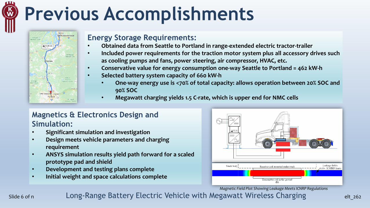
Energy Storage Requirements:• Obtained data from Seattle to Portland in range-extended electric tractor-trailer• Included power requirements for the traction motor system plus all accessory drives such
as cooling pumps and fans, power steering, air compressor, HVAC, etc.• Conservative value for energy consumption one-way Seattle to Portland = 462 kW-h• Selected battery system capacity of 660 kW-h
• One-way energy use is <70% of total capacity: allows operation between 20% SOC and90% SOC
• Megawatt charging yields 1.5 C-rate, which is upper end for NMC cells
Magnetics & Electronics Design and
Simulation:• Significant simulation and investigation• Design meets vehicle parameters and charging
requirement• ANSYS simulation results yield path forward for a scaled
prototype pad and shield• Development and testing plans complete• Initial weight and space calculations complete
Magnetic Field Plot Showing Leakage Meets ICNRP Regulations

Accomplishments- Wireless Charger Design
Slide 7 of nLong-Range Battery Electric Vehicle with Megawatt Wireless Charging
elt_262
Key system parameters:• 660 kWh battery @ 1.5 C charging rate• 390 to 475 kWh of energy in 23 to 29 minutes @ 1 MW• 480V 3-ϕ AC input (Grid voltage)• 649 V –755 V DC output (Battery voltage)• 8 inverter modules x 125 kW per module• >90% targeted efficiency• Leakage fields <15 μT (ANSI 14117 standard)• Air gap of 300 mm• Receiver weight < 3125 lbs
Magnetics design:• Key design features
• Power transfer achieved at large air gap (300 mm)• Meets public safety field exposure limits (ANSI 14117)• Integrated electronics in the pad enclosure• Allocated pad space: 5' x 5'• Estimated weight < 3125 lbs• Operating frequency: 85 kHz
• Key innovations:• Developed new optimization method that considers circuit
topology and magnetics design to find optimal designs for maximum performance
• Design avoids complex interleaving which significantly simplifies cooling design
• Designs evaluated:• Active field cancellation vs passive field cancellation• Various aluminum shield designs to minimize impact of truck
chassis
• Matching battery charge profile required 8 modules vs 4.• Established all component parameters in design phase.
• Single stage AC-AC• High Efficiency• No bulky DC link capacitors
Unfolder + T-type converter

Accomplishments- Wireless Charger Testing
Slide 8 of nLong-Range Battery Electric Vehicle with Megawatt Wireless Charging
elt_262
• Successfully tested one module (125kW) through charge plates.• Achieved 93% DC-DC efficiency in initial test
Parameter Value
Vout 573 volts
Iout 218 amps
Output Power 125 kW
Losses 9.66 kW
DC-DC Efficiency 93%
M
H-Bridge
/ T-Type
VOutVin
IOut
+
-
Iin
Diode BridgeSecondary
Compensation
Primary
Compensation Wireless
Charging
Pads
Accomplishments- Battery Charge Profile
Slide 9 of nLong-Range Battery Electric Vehicle with Megawatt Wireless Charging
elt_262
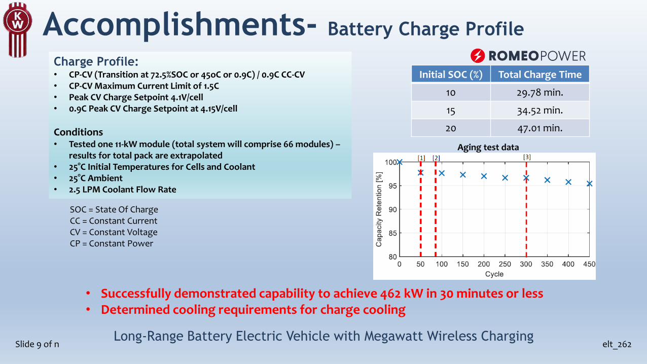
• Successfully demonstrated capability to achieve 462 kW in 30 minutes or less• Determined cooling requirements for charge cooling
Charge Profile:• CP-CV (Transition at 72.5%SOC or 45oC or 0.9C) / 0.9C CC-CV• CP-CV Maximum Current Limit of 1.5C• Peak CV Charge Setpoint 4.1V/cell • 0.9C Peak CV Charge Setpoint at 4.15V/cell
Conditions• Tested one 11-kW module (total system will comprise 66 modules) –
results for total pack are extrapolated• 25°C Initial Temperatures for Cells and Coolant• 25°C Ambient• 2.5 LPM Coolant Flow Rate
Initial SOC (%) Total Charge Time
10 29.78 min.
15 34.52 min.
20 47.01 min.
SOC = State Of ChargeCC = Constant CurrentCV = Constant VoltageCP = Constant Power
Aging test data

Accomplishments- BEV Design
Slide 10 of nLong-Range Battery Electric Vehicle with Megawatt Wireless Charging
elt_262
Key vehicle attributes:• Kenworth mode: T680 Daycab• Wheelbase: 220”• Traction motor power: 350 kW continuous• Two voltage buses: 650V and 12V. All components
>1 kW are 650V• Estimated tare weights:
Front 13,000 lbsRear 14,000 lbsTotal 27,000 lbs
• Tractor is expected to be drivable in August 2021
Current status:• All components on order; many received• Chassis is being fitted with components• Pacing item is motor/inverter/transmission – expected mid-June
Side Pack2 Side HVBatteries
Traction Motor/Inverter/T
ransmission
High-Voltage Power Distribution
Tower Packs
4 Upper HV Batteries
Wireless Charge Plate
Cooling Module
PowerElectronics
BatteryCooling/Chilling
PowerSteering
AirCompressor
FWD
Chassis component locations
Charge plate mounting
Airflow during charging
Thermal systems attributes:• One WEG radiator; 2 refrigerant condensers; 1 large 650V fan• Batteries cooled by chilled Water/Ethylene Glycol (WEG), each of 6
packs in parallel• Cab HVAC shares refrigerant with battery system; heaters separate• Charger cooled by WEG radiator; simulation shows adequate
cooling when charging at 1 MW rate

Prior AMR Comments/Questions
Slide 11 of n elt_262Long-Range Battery Electric Vehicle with Megawatt Wireless Charging
Was energy consumption from SuperTruckII used in this project?
• No, because we needed energy consumption for a specific route (Seattle to Portland and return). A range-extended electric truck was driven on the route, and electrical energy consumption measured. SuperTruckII data were used as a comparison to ensure that results were reasonable.
It was not clear why wireless charging is preferred at this level of power transfer and vehicle
specialization.
• Cable-connected charging at megawatt rate was expected to require a very large cable size (for 1500+ amps), and was expected to need to be a cooled cable. A cooled connector would need to be developed. High-Voltage, High-Current connections may require an electrician to connect, especially at union facilities. Wireless charging avoids these issues.
The cost of the battery and the incremental wireless infrastructure looks cost prohibitive
• Cost remains a concern. The battery system chosen utilizes high-production-volume NMC cells, a choice intended to optimize battery cost, size and weight. Wireless chargers at lower rates have shown commercial advantages, but this remains to be uncovered during this project at megawatt rate.

Collaboration and Coordination
Slide 12 of n elt_262Long-Range Battery Electric Vehicle with Megawatt Wireless Charging
A strong and diverse team of partners has been established:
Kenworth Truck Co. division of PACCAR – Prime RecipientHeavy Truck OEM. Project leadership and vehicle devlopment
UPSGlobal Transportation and Logistics Fleet. Providing location for charging equipment; will operate test vehicle in fleet operations
Utah State UniversityAcademic Institution with Extensive Wireless Power Transfer Expertise. Wireless Power Transfer design & development
WAVETechnology Startup Producing & Deploying Wireless Chargers for Heavy Vehicles. Build and commercialize Wireless Power Transfer equipment
Seattle City LightLocal Government-Owned Public Utility. Providing grid power and consultation at Seattle charging site
Portland General ElectricLocal Public Utility. Providing power and consultation at Portland charging site
Romeo PowerBattery Technology Company. Battery development

Remaining Challenges and Barriers
Slide 13 of n elt_262Long-Range Battery Electric Vehicle with Megawatt Wireless Charging
Technical Challenges:
• Achieving the required energy transfer in the desired time without over-voltage or over-current in the battery system remains a concern. Early testing results indicate this can be achieved when the batteries are new; aging of the batteries may slow charge times.
• Thermal management of the batteries during charging is a concern. Simulation and analysis indicates the cooling system is properly designed, but testing may reveal unexpected issues.
• Electrical noise from the charger may affect CAN communications. Steps are being taken to reduce noise and to shield communication lines, but issues may arise once the full vehicle is in operation.
• Complete charging system efficiency including ground-side cooling and vehicle-side cooling may be low enough to reduce the attractiveness of this technology.
• This project will develop a proof-of-concept system of one BEV tractor and two wireless chargers for a total cost of $10M. Can this technology be produced at affordable costs when scaled to higher volumes?
Barriers:
• COVID has resulted in global component shortages and delivery delays. This has slowed progress in building the chassis and the charging system.

Proposed Future Research
Slide 14 of n elt_262Long-Range Battery Electric Vehicle with Megawatt Wireless Charging
Any proposed future work is subject to change based on funding levels.
2021 FY:
• Characterize the single stage AC-AC converter operation, transmitter coil and receiver coil, compensation tank and receiver diode bridge in terms of electric performance and thermal behavior.
• Complete the design and installation plans for each charger site (Seattle and Portland), and start the permitting process.
• Begin commercialization of the charging system.
• Complete the build of the vehicle and initiate functional testing (using 150 kW plug-in charger).
2022 FY:
• Complete the build of the charging equipment.
• Demonstrate the charging system off-vehicle at megawatt rate.
• Complete the installation of the grid power supply and charging equipment at each charging location.
• Install the charging receiver plate on the vehicle and validate power transfer to battery system.
• Commence commercial operations with the BEV tractor and wireless charging system.
Summary
Slide 15 of n elt_262Long-Range Battery Electric Vehicle with Megawatt Wireless Charging
Technical Accomplishments:
• Validated through physical testing that 462 kW-h of energy can be added to a 660-kW-h battery system in 30 minutes or less.
• Validated through physical testing that one inverter module (125 kW) can transmit power across a 300-mm [11.8 in] air gap at 93% DC-DC efficiency.
• Developed thermal management systems for the vehicle side to cool the charge plate, batteries, traction motor/inverter/transmission, auxiliary device motors and power electronics, in addition to cab HVAC. Conducted air flow and coolant flow simulations to show adequate cooling in expected worst-case scenarios.
• Completed vehicle layout and detail design drawings, and placed orders for all components.
• Developing vehicle control system to manage on-board components and systems – 50% complete.

elt_262Long-Range Battery Electric Vehicle with Megawatt Wireless Charging
(End of presentation)